JP2015150892A - formation of thermoplastic parts - Google Patents
formation of thermoplastic partsDownload PDFInfo
- Publication number
- JP2015150892A JP2015150892AJP2015020905AJP2015020905AJP2015150892AJP 2015150892 AJP2015150892 AJP 2015150892AJP 2015020905 AJP2015020905 AJP 2015020905AJP 2015020905 AJP2015020905 AJP 2015020905AJP 2015150892 AJP2015150892 AJP 2015150892A
- Authority
- JP
- Japan
- Prior art keywords
- mold
- surface shape
- shape portion
- thermoplastic material
- partial body
- Prior art date
- Legal status (The legal status is an assumption and is not a legal conclusion. Google has not performed a legal analysis and makes no representation as to the accuracy of the status listed.)
- Pending
Links
- 229920001169thermoplasticPolymers0.000titleclaimsabstractdescription45
- 239000004416thermosoftening plasticSubstances0.000titleclaimsabstractdescription45
- 230000015572biosynthetic processEffects0.000titledescription3
- 238000004519manufacturing processMethods0.000claimsabstractdescription62
- 230000001681protective effectEffects0.000claimsabstractdescription59
- 238000000034methodMethods0.000claimsabstractdescription58
- 239000012815thermoplastic materialSubstances0.000claimsabstractdescription56
- 239000000654additiveSubstances0.000claimsabstractdescription26
- 230000000996additive effectEffects0.000claimsabstractdescription26
- 238000010438heat treatmentMethods0.000claimsdescription21
- 238000000465mouldingMethods0.000claimsdescription17
- 238000005520cutting processMethods0.000claimsdescription16
- 238000002844meltingMethods0.000claimsdescription10
- 230000008018meltingEffects0.000claimsdescription10
- XLYOFNOQVPJJNP-UHFFFAOYSA-NwaterSubstancesOXLYOFNOQVPJJNP-UHFFFAOYSA-N0.000claimsdescription7
- 238000000149argon plasma sinteringMethods0.000claimsdescription4
- 230000000844anti-bacterial effectEffects0.000claimsdescription3
- 230000035699permeabilityEffects0.000claimsdescription3
- 239000000126substanceSubstances0.000claimsdescription3
- 239000000463materialSubstances0.000description20
- 230000008569processEffects0.000description20
- 238000013461designMethods0.000description10
- 239000002184metalSubstances0.000description10
- 238000012545processingMethods0.000description9
- 238000010586diagramMethods0.000description8
- 239000002861polymer materialSubstances0.000description6
- 238000012423maintenanceMethods0.000description5
- 238000001125extrusionMethods0.000description4
- 229920001702kydexPolymers0.000description4
- 238000012986modificationMethods0.000description3
- 230000004048modificationEffects0.000description3
- 229920000642polymerPolymers0.000description3
- 229920001187thermosetting polymerPolymers0.000description3
- KAKZBPTYRLMSJV-UHFFFAOYSA-NButadieneChemical compoundC=CC=CKAKZBPTYRLMSJV-UHFFFAOYSA-N0.000description2
- PPBRXRYQALVLMV-UHFFFAOYSA-NStyreneChemical compoundC=CC1=CC=CC=C1PPBRXRYQALVLMV-UHFFFAOYSA-N0.000description2
- XECAHXYUAAWDEL-UHFFFAOYSA-Nacrylonitrile butadiene styreneChemical compoundC=CC=C.C=CC#N.C=CC1=CC=CC=C1XECAHXYUAAWDEL-UHFFFAOYSA-N0.000description2
- 239000004676acrylonitrile butadiene styreneSubstances0.000description2
- 229920000122acrylonitrile butadiene styrenePolymers0.000description2
- 239000000853adhesiveSubstances0.000description2
- 230000001070adhesive effectEffects0.000description2
- 230000010354integrationEffects0.000description2
- 230000008520organizationEffects0.000description2
- 230000037303wrinklesEffects0.000description2
- NLHHRLWOUZZQLW-UHFFFAOYSA-NAcrylonitrileChemical compoundC=CC#NNLHHRLWOUZZQLW-UHFFFAOYSA-N0.000description1
- NIXOWILDQLNWCW-UHFFFAOYSA-Nacrylic acid groupChemical groupC(C=C)(=O)ONIXOWILDQLNWCW-UHFFFAOYSA-N0.000description1
- 230000002411adverseEffects0.000description1
- 238000007796conventional methodMethods0.000description1
- 238000001816coolingMethods0.000description1
- 230000007547defectEffects0.000description1
- 230000007613environmental effectEffects0.000description1
- 239000006261foam materialSubstances0.000description1
- 239000004816latexSubstances0.000description1
- 229920000126latexPolymers0.000description1
- 238000003754machiningMethods0.000description1
- 238000003801millingMethods0.000description1
- 230000000737periodic effectEffects0.000description1
- 239000004800polyvinyl chlorideSubstances0.000description1
- 229920000915polyvinyl chloridePolymers0.000description1
- 238000004080punchingMethods0.000description1
- 239000000565sealantSubstances0.000description1
- 239000007787solidSubstances0.000description1
- 229920002994synthetic fiberPolymers0.000description1
Images


Classifications
- B—PERFORMING OPERATIONS; TRANSPORTING
- B29—WORKING OF PLASTICS; WORKING OF SUBSTANCES IN A PLASTIC STATE IN GENERAL
- B29C—SHAPING OR JOINING OF PLASTICS; SHAPING OF MATERIAL IN A PLASTIC STATE, NOT OTHERWISE PROVIDED FOR; AFTER-TREATMENT OF THE SHAPED PRODUCTS, e.g. REPAIRING
- B29C51/00—Shaping by thermoforming, i.e. shaping sheets or sheet like preforms after heating, e.g. shaping sheets in matched moulds or by deep-drawing; Apparatus therefor
- B29C51/02—Combined thermoforming and manufacture of the preform
- B—PERFORMING OPERATIONS; TRANSPORTING
- B29—WORKING OF PLASTICS; WORKING OF SUBSTANCES IN A PLASTIC STATE IN GENERAL
- B29C—SHAPING OR JOINING OF PLASTICS; SHAPING OF MATERIAL IN A PLASTIC STATE, NOT OTHERWISE PROVIDED FOR; AFTER-TREATMENT OF THE SHAPED PRODUCTS, e.g. REPAIRING
- B29C51/00—Shaping by thermoforming, i.e. shaping sheets or sheet like preforms after heating, e.g. shaping sheets in matched moulds or by deep-drawing; Apparatus therefor
- B29C51/10—Forming by pressure difference, e.g. vacuum
- B—PERFORMING OPERATIONS; TRANSPORTING
- B29—WORKING OF PLASTICS; WORKING OF SUBSTANCES IN A PLASTIC STATE IN GENERAL
- B29C—SHAPING OR JOINING OF PLASTICS; SHAPING OF MATERIAL IN A PLASTIC STATE, NOT OTHERWISE PROVIDED FOR; AFTER-TREATMENT OF THE SHAPED PRODUCTS, e.g. REPAIRING
- B29C51/00—Shaping by thermoforming, i.e. shaping sheets or sheet like preforms after heating, e.g. shaping sheets in matched moulds or by deep-drawing; Apparatus therefor
- B29C51/18—Thermoforming apparatus
- B—PERFORMING OPERATIONS; TRANSPORTING
- B29—WORKING OF PLASTICS; WORKING OF SUBSTANCES IN A PLASTIC STATE IN GENERAL
- B29C—SHAPING OR JOINING OF PLASTICS; SHAPING OF MATERIAL IN A PLASTIC STATE, NOT OTHERWISE PROVIDED FOR; AFTER-TREATMENT OF THE SHAPED PRODUCTS, e.g. REPAIRING
- B29C51/00—Shaping by thermoforming, i.e. shaping sheets or sheet like preforms after heating, e.g. shaping sheets in matched moulds or by deep-drawing; Apparatus therefor
- B29C51/26—Component parts, details or accessories; Auxiliary operations
- B29C51/263—Component parts, details or accessories; Auxiliary operations characterised by using a particular environment, e.g. sterile
- B—PERFORMING OPERATIONS; TRANSPORTING
- B29—WORKING OF PLASTICS; WORKING OF SUBSTANCES IN A PLASTIC STATE IN GENERAL
- B29C—SHAPING OR JOINING OF PLASTICS; SHAPING OF MATERIAL IN A PLASTIC STATE, NOT OTHERWISE PROVIDED FOR; AFTER-TREATMENT OF THE SHAPED PRODUCTS, e.g. REPAIRING
- B29C51/00—Shaping by thermoforming, i.e. shaping sheets or sheet like preforms after heating, e.g. shaping sheets in matched moulds or by deep-drawing; Apparatus therefor
- B29C51/26—Component parts, details or accessories; Auxiliary operations
- B29C51/264—Auxiliary operations prior to the thermoforming operation, e.g. cutting
- B—PERFORMING OPERATIONS; TRANSPORTING
- B29—WORKING OF PLASTICS; WORKING OF SUBSTANCES IN A PLASTIC STATE IN GENERAL
- B29C—SHAPING OR JOINING OF PLASTICS; SHAPING OF MATERIAL IN A PLASTIC STATE, NOT OTHERWISE PROVIDED FOR; AFTER-TREATMENT OF THE SHAPED PRODUCTS, e.g. REPAIRING
- B29C51/00—Shaping by thermoforming, i.e. shaping sheets or sheet like preforms after heating, e.g. shaping sheets in matched moulds or by deep-drawing; Apparatus therefor
- B29C51/26—Component parts, details or accessories; Auxiliary operations
- B29C51/30—Moulds
- B29C51/36—Moulds specially adapted for vacuum forming, Manufacture thereof
- B—PERFORMING OPERATIONS; TRANSPORTING
- B29—WORKING OF PLASTICS; WORKING OF SUBSTANCES IN A PLASTIC STATE IN GENERAL
- B29C—SHAPING OR JOINING OF PLASTICS; SHAPING OF MATERIAL IN A PLASTIC STATE, NOT OTHERWISE PROVIDED FOR; AFTER-TREATMENT OF THE SHAPED PRODUCTS, e.g. REPAIRING
- B29C51/00—Shaping by thermoforming, i.e. shaping sheets or sheet like preforms after heating, e.g. shaping sheets in matched moulds or by deep-drawing; Apparatus therefor
- B29C51/26—Component parts, details or accessories; Auxiliary operations
- B29C51/42—Heating or cooling
- B—PERFORMING OPERATIONS; TRANSPORTING
- B29—WORKING OF PLASTICS; WORKING OF SUBSTANCES IN A PLASTIC STATE IN GENERAL
- B29C—SHAPING OR JOINING OF PLASTICS; SHAPING OF MATERIAL IN A PLASTIC STATE, NOT OTHERWISE PROVIDED FOR; AFTER-TREATMENT OF THE SHAPED PRODUCTS, e.g. REPAIRING
- B29C51/00—Shaping by thermoforming, i.e. shaping sheets or sheet like preforms after heating, e.g. shaping sheets in matched moulds or by deep-drawing; Apparatus therefor
- B29C51/26—Component parts, details or accessories; Auxiliary operations
- B29C51/46—Measuring, controlling or regulating
- B—PERFORMING OPERATIONS; TRANSPORTING
- B29—WORKING OF PLASTICS; WORKING OF SUBSTANCES IN A PLASTIC STATE IN GENERAL
- B29C—SHAPING OR JOINING OF PLASTICS; SHAPING OF MATERIAL IN A PLASTIC STATE, NOT OTHERWISE PROVIDED FOR; AFTER-TREATMENT OF THE SHAPED PRODUCTS, e.g. REPAIRING
- B29C64/00—Additive manufacturing, i.e. manufacturing of three-dimensional [3D] objects by additive deposition, additive agglomeration or additive layering, e.g. by 3D printing, stereolithography or selective laser sintering
- B29C64/10—Processes of additive manufacturing
- B29C64/141—Processes of additive manufacturing using only solid materials
- B29C64/147—Processes of additive manufacturing using only solid materials using sheet material, e.g. laminated object manufacturing [LOM] or laminating sheet material precut to local cross sections of the 3D object
- B—PERFORMING OPERATIONS; TRANSPORTING
- B29—WORKING OF PLASTICS; WORKING OF SUBSTANCES IN A PLASTIC STATE IN GENERAL
- B29C—SHAPING OR JOINING OF PLASTICS; SHAPING OF MATERIAL IN A PLASTIC STATE, NOT OTHERWISE PROVIDED FOR; AFTER-TREATMENT OF THE SHAPED PRODUCTS, e.g. REPAIRING
- B29C64/00—Additive manufacturing, i.e. manufacturing of three-dimensional [3D] objects by additive deposition, additive agglomeration or additive layering, e.g. by 3D printing, stereolithography or selective laser sintering
- B29C64/10—Processes of additive manufacturing
- B29C64/188—Processes of additive manufacturing involving additional operations performed on the added layers, e.g. smoothing, grinding or thickness control
- B—PERFORMING OPERATIONS; TRANSPORTING
- B29—WORKING OF PLASTICS; WORKING OF SUBSTANCES IN A PLASTIC STATE IN GENERAL
- B29C—SHAPING OR JOINING OF PLASTICS; SHAPING OF MATERIAL IN A PLASTIC STATE, NOT OTHERWISE PROVIDED FOR; AFTER-TREATMENT OF THE SHAPED PRODUCTS, e.g. REPAIRING
- B29C64/00—Additive manufacturing, i.e. manufacturing of three-dimensional [3D] objects by additive deposition, additive agglomeration or additive layering, e.g. by 3D printing, stereolithography or selective laser sintering
- B29C64/20—Apparatus for additive manufacturing; Details thereof or accessories therefor
- B—PERFORMING OPERATIONS; TRANSPORTING
- B33—ADDITIVE MANUFACTURING TECHNOLOGY
- B33Y—ADDITIVE MANUFACTURING, i.e. MANUFACTURING OF THREE-DIMENSIONAL [3-D] OBJECTS BY ADDITIVE DEPOSITION, ADDITIVE AGGLOMERATION OR ADDITIVE LAYERING, e.g. BY 3-D PRINTING, STEREOLITHOGRAPHY OR SELECTIVE LASER SINTERING
- B33Y80/00—Products made by additive manufacturing
- C—CHEMISTRY; METALLURGY
- C08—ORGANIC MACROMOLECULAR COMPOUNDS; THEIR PREPARATION OR CHEMICAL WORKING-UP; COMPOSITIONS BASED THEREON
- C08J—WORKING-UP; GENERAL PROCESSES OF COMPOUNDING; AFTER-TREATMENT NOT COVERED BY SUBCLASSES C08B, C08C, C08F, C08G or C08H
- C08J5/00—Manufacture of articles or shaped materials containing macromolecular substances
- B—PERFORMING OPERATIONS; TRANSPORTING
- B29—WORKING OF PLASTICS; WORKING OF SUBSTANCES IN A PLASTIC STATE IN GENERAL
- B29C—SHAPING OR JOINING OF PLASTICS; SHAPING OF MATERIAL IN A PLASTIC STATE, NOT OTHERWISE PROVIDED FOR; AFTER-TREATMENT OF THE SHAPED PRODUCTS, e.g. REPAIRING
- B29C2791/00—Shaping characteristics in general
- B29C2791/004—Shaping under special conditions
- B29C2791/006—Using vacuum
- B—PERFORMING OPERATIONS; TRANSPORTING
- B29—WORKING OF PLASTICS; WORKING OF SUBSTANCES IN A PLASTIC STATE IN GENERAL
- B29C—SHAPING OR JOINING OF PLASTICS; SHAPING OF MATERIAL IN A PLASTIC STATE, NOT OTHERWISE PROVIDED FOR; AFTER-TREATMENT OF THE SHAPED PRODUCTS, e.g. REPAIRING
- B29C51/00—Shaping by thermoforming, i.e. shaping sheets or sheet like preforms after heating, e.g. shaping sheets in matched moulds or by deep-drawing; Apparatus therefor
- B29C51/26—Component parts, details or accessories; Auxiliary operations
- B29C51/28—Component parts, details or accessories; Auxiliary operations for applying pressure through the wall of an inflated bag or diaphragm
- B—PERFORMING OPERATIONS; TRANSPORTING
- B29—WORKING OF PLASTICS; WORKING OF SUBSTANCES IN A PLASTIC STATE IN GENERAL
- B29C—SHAPING OR JOINING OF PLASTICS; SHAPING OF MATERIAL IN A PLASTIC STATE, NOT OTHERWISE PROVIDED FOR; AFTER-TREATMENT OF THE SHAPED PRODUCTS, e.g. REPAIRING
- B29C51/00—Shaping by thermoforming, i.e. shaping sheets or sheet like preforms after heating, e.g. shaping sheets in matched moulds or by deep-drawing; Apparatus therefor
- B29C51/26—Component parts, details or accessories; Auxiliary operations
- B29C51/30—Moulds
- B—PERFORMING OPERATIONS; TRANSPORTING
- B29—WORKING OF PLASTICS; WORKING OF SUBSTANCES IN A PLASTIC STATE IN GENERAL
- B29K—INDEXING SCHEME ASSOCIATED WITH SUBCLASSES B29B, B29C OR B29D, RELATING TO MOULDING MATERIALS OR TO MATERIALS FOR MOULDS, REINFORCEMENTS, FILLERS OR PREFORMED PARTS, e.g. INSERTS
- B29K2101/00—Use of unspecified macromolecular compounds as moulding material
- B29K2101/12—Thermoplastic materials
- B—PERFORMING OPERATIONS; TRANSPORTING
- B29—WORKING OF PLASTICS; WORKING OF SUBSTANCES IN A PLASTIC STATE IN GENERAL
- B29L—INDEXING SCHEME ASSOCIATED WITH SUBCLASS B29C, RELATING TO PARTICULAR ARTICLES
- B29L2022/00—Hollow articles
- B—PERFORMING OPERATIONS; TRANSPORTING
- B29—WORKING OF PLASTICS; WORKING OF SUBSTANCES IN A PLASTIC STATE IN GENERAL
- B29L—INDEXING SCHEME ASSOCIATED WITH SUBCLASS B29C, RELATING TO PARTICULAR ARTICLES
- B29L2031/00—Other particular articles
- B29L2031/757—Moulds, cores, dies
- B—PERFORMING OPERATIONS; TRANSPORTING
- B29—WORKING OF PLASTICS; WORKING OF SUBSTANCES IN A PLASTIC STATE IN GENERAL
- B29L—INDEXING SCHEME ASSOCIATED WITH SUBCLASS B29C, RELATING TO PARTICULAR ARTICLES
- B29L2031/00—Other particular articles
- B29L2031/768—Protective equipment
- B—PERFORMING OPERATIONS; TRANSPORTING
- B33—ADDITIVE MANUFACTURING TECHNOLOGY
- B33Y—ADDITIVE MANUFACTURING, i.e. MANUFACTURING OF THREE-DIMENSIONAL [3-D] OBJECTS BY ADDITIVE DEPOSITION, ADDITIVE AGGLOMERATION OR ADDITIVE LAYERING, e.g. BY 3-D PRINTING, STEREOLITHOGRAPHY OR SELECTIVE LASER SINTERING
- B33Y10/00—Processes of additive manufacturing
- B—PERFORMING OPERATIONS; TRANSPORTING
- B33—ADDITIVE MANUFACTURING TECHNOLOGY
- B33Y—ADDITIVE MANUFACTURING, i.e. MANUFACTURING OF THREE-DIMENSIONAL [3-D] OBJECTS BY ADDITIVE DEPOSITION, ADDITIVE AGGLOMERATION OR ADDITIVE LAYERING, e.g. BY 3-D PRINTING, STEREOLITHOGRAPHY OR SELECTIVE LASER SINTERING
- B33Y30/00—Apparatus for additive manufacturing; Details thereof or accessories therefor
- B—PERFORMING OPERATIONS; TRANSPORTING
- B33—ADDITIVE MANUFACTURING TECHNOLOGY
- B33Y—ADDITIVE MANUFACTURING, i.e. MANUFACTURING OF THREE-DIMENSIONAL [3-D] OBJECTS BY ADDITIVE DEPOSITION, ADDITIVE AGGLOMERATION OR ADDITIVE LAYERING, e.g. BY 3-D PRINTING, STEREOLITHOGRAPHY OR SELECTIVE LASER SINTERING
- B33Y50/00—Data acquisition or data processing for additive manufacturing
- C—CHEMISTRY; METALLURGY
- C08—ORGANIC MACROMOLECULAR COMPOUNDS; THEIR PREPARATION OR CHEMICAL WORKING-UP; COMPOSITIONS BASED THEREON
- C08J—WORKING-UP; GENERAL PROCESSES OF COMPOUNDING; AFTER-TREATMENT NOT COVERED BY SUBCLASSES C08B, C08C, C08F, C08G or C08H
- C08J2300/00—Characterised by the use of unspecified polymers
- C08J2300/22—Thermoplastic resins
- Y—GENERAL TAGGING OF NEW TECHNOLOGICAL DEVELOPMENTS; GENERAL TAGGING OF CROSS-SECTIONAL TECHNOLOGIES SPANNING OVER SEVERAL SECTIONS OF THE IPC; TECHNICAL SUBJECTS COVERED BY FORMER USPC CROSS-REFERENCE ART COLLECTIONS [XRACs] AND DIGESTS
- Y10—TECHNICAL SUBJECTS COVERED BY FORMER USPC
- Y10T—TECHNICAL SUBJECTS COVERED BY FORMER US CLASSIFICATION
- Y10T428/00—Stock material or miscellaneous articles
- Y10T428/13—Hollow or container type article [e.g., tube, vase, etc.]
- Y10T428/1352—Polymer or resin containing [i.e., natural or synthetic]
- Y10T428/1397—Single layer [continuous layer]
Landscapes
- Engineering & Computer Science (AREA)
- Mechanical Engineering (AREA)
- Chemical & Material Sciences (AREA)
- Materials Engineering (AREA)
- Manufacturing & Machinery (AREA)
- Physics & Mathematics (AREA)
- Optics & Photonics (AREA)
- Health & Medical Sciences (AREA)
- Chemical Kinetics & Catalysis (AREA)
- Medicinal Chemistry (AREA)
- Polymers & Plastics (AREA)
- Organic Chemistry (AREA)
- Toxicology (AREA)
- Blow-Moulding Or Thermoforming Of Plastics Or The Like (AREA)
- Moulds For Moulding Plastics Or The Like (AREA)
- Shaping Of Tube Ends By Bending Or Straightening (AREA)
Abstract
Description
Translated fromJapanese本開示は、概して熱可塑性部品の形成に関し、特に、着脱式保護要素の形成に関する。より具体的には、本開示は、熱可塑性シートから熱可塑性部品を形成するための方法及び装置に関する。 The present disclosure relates generally to the formation of thermoplastic parts, and in particular to the formation of a removable protective element. More specifically, the present disclosure relates to a method and apparatus for forming a thermoplastic part from a thermoplastic sheet.
ポリマー材料は、航空機の内装部品を含む様々な製品に用いることができる。ポリマー材料とは、例えば、熱可塑性材料や、熱硬化性材料である。熱可塑性材料とは、例えば、選択された温度を超えると屈曲又は成形が可能になり、冷却すると固体に戻るポリマーである。熱可塑性材料は、繰り返し加熱及び冷却することができる。熱硬化性材料は、加熱すると、硬化する。熱硬化性材料は、加熱すると、不可逆的に硬化する。 The polymer material can be used in a variety of products including aircraft interior parts. The polymer material is, for example, a thermoplastic material or a thermosetting material. A thermoplastic material is, for example, a polymer that can be bent or molded above a selected temperature and returns to a solid upon cooling. The thermoplastic material can be repeatedly heated and cooled. The thermosetting material cures when heated. A thermosetting material cures irreversibly when heated.
ポリマー材料は、押し出し、引き抜き、付加製造、及び成形等の様々な方法を用いて、部品として形成することができる。押し出しや引き抜きを用いて部品を形成すると、作製される部品の形状が制限されることがある。さらに、押し出しや引き抜きは、成形型(tooling)のコストが高くなる可能性がある。 The polymeric material can be formed as a part using various methods such as extrusion, drawing, additive manufacturing, and molding. When a part is formed using extrusion or drawing, the shape of the produced part may be limited. Further, extrusion and drawing can increase the cost of tooling.
付加製造を用いてポリマー材料から部品を形成すると、結果的に、その部品が望まれない特性を有することもある。例えば、付加製造により、部品が独立した個々の層を有することもある。さらに、付加製造技術では、部品の形成に使用できるポリマー材料が制限される場合がある。 Forming a part from a polymeric material using additive manufacturing can result in the part having undesirable properties. For example, due to additive manufacturing, a part may have separate individual layers. Further, additive manufacturing techniques may limit the polymer material that can be used to form the part.
ポリマー材料の成形に用いられるモールドは、ミリング処理又は他の材料除去処理を用いて金属から作製することができる。モールドを金属で作製する理由としては、金属製のモールドは、ポリマー材料の成形に複数回使用することができ、このように複数回使用しても、悪影響を受けることがないからである。しかしながら、金属製モールドは、コスト負担が大きい。さらに、金属製モールドの製造には、時間がかかる。また、金属製モールドを収容するために、多大なスペースが必要である。 The mold used to form the polymer material can be made from metal using a milling process or other material removal process. The reason why the mold is made of metal is that a metal mold can be used for molding a polymer material a plurality of times, and even if it is used a plurality of times in this way, it is not adversely affected. However, the metal mold has a large cost burden. Furthermore, it takes time to manufacture a metal mold. In addition, a large space is required to accommodate the metal mold.
したがって、金属製モールドは、いくつかの同種のポリマー部品の作製に用いることが望ましいと考えられる。さらに、作製する部品の数が増加すると、金属製モールドを用いて作製されるポリマー部品1つ当たりのコストは低下すると考えられる。しかしながら、ポリマー材料から、単一の部品を形成すると、コストや時間がかかり望ましくない。 Thus, it may be desirable to use a metal mold to make several similar polymer parts. Furthermore, as the number of parts to be produced increases, the cost per polymer part produced using a metal mold is considered to decrease. However, forming a single part from a polymer material is undesirable because of cost and time.
したがって、上述した問題のうち少なくともいくつかと、その他の考えられる問題を考慮にいれた方法及び装置を有することが望ましい。 Accordingly, it would be desirable to have a method and apparatus that takes into account at least some of the issues discussed above and other possible issues.
本開示の例示的な一実施形態では、着脱式保護要素が提供される。着脱式保護要素は、部品の表面の外面形状部に密着するように、熱可塑性材料を均一の厚みを有するように成形してなる成形体を含む。成形体は、着脱式保護要素を部品に密着させるように構成された特異部を有する内面形状部を含む。 In an exemplary embodiment of the present disclosure, a removable protection element is provided. The removable protective element includes a molded body formed by molding a thermoplastic material so as to have a uniform thickness so as to be in close contact with the outer surface shape portion of the surface of the component. The molded body includes an inner surface shape portion having a unique portion configured to closely attach the detachable protection element to the component.
本開示の他の例示的な一実施形態では、方法が提供される。三次元モデルに基づいて、第1熱可塑性材料からなる熱可塑性シートから、部分体が切り取られる。部分体はモールドに固定される。部分体及びモールドを真空下で加熱することにより構造体が形成される。 In another exemplary embodiment of the present disclosure, a method is provided. Based on the three-dimensional model, a partial body is cut out from the thermoplastic sheet made of the first thermoplastic material. The partial body is fixed to the mold. The structure is formed by heating the partial body and the mold under vacuum.
本開示の他の例示的な一実施形態では、方法が提供される。部品の表面は、部品の三次元モデルから識別される。モールド表面の表面形状部は、三次元モデルに基づいてデザインされる。表面形状部は、修正され、修正表面形状部となる。モールドは、付加製造により、修正表面形状部に基づいて形成される。扁平体は、三次元モデルに基づいてデザインされる。扁平体は、部分体を形成するための熱可塑性シートから切り取られる。部分体はモールドに固定される。部分体及びモールドを真空下で加熱することにより構造体が形成される。 In another exemplary embodiment of the present disclosure, a method is provided. The surface of the part is identified from the three-dimensional model of the part. The surface shape portion of the mold surface is designed based on a three-dimensional model. The surface shape portion is corrected to become a corrected surface shape portion. The mold is formed on the basis of the modified surface shape portion by additive manufacturing. The flat body is designed based on a three-dimensional model. The flat body is cut out from the thermoplastic sheet for forming the partial body. The partial body is fixed to the mold. The structure is formed by heating the partial body and the mold under vacuum.
本開示における、さらに他の例示的な一実施形態では、装置が提供される。装置は、デザイン手段と、形状生成手段と、成形システムとを備える。デザイン手段は、部品の表面を識別して、部品の表面を覆うようにデザインされた構造体のための扁平体を作製するように構成されている。形状生成手段は、扁平体を用いて、熱可塑性シートから部分体を形成するように構成されている。成形システムは、扁平形状を有する熱可塑性シートを用いて、部品の表面を覆うようにデザインされた保護構造体を形成するように構成されている。 In yet another exemplary embodiment of the present disclosure, an apparatus is provided. The apparatus includes design means, shape generation means, and a molding system. The design means is configured to identify a surface of the part and produce a flat body for a structure designed to cover the surface of the part. The shape generating means is configured to form a partial body from a thermoplastic sheet using a flat body. The molding system is configured to form a protective structure designed to cover the surface of the part using a thermoplastic sheet having a flat shape.
要約すれば、本発明の一態様によると、部品の表面の外面形状部に密着するように、熱可塑性材料を均一の厚みを有するように成形してなる成形体を含む着脱式保護要素が提供され、成形体は、着脱式保護要素を部品に密着させるように構成された特異部を有する内面形状部を含む。 In summary, according to one aspect of the present invention, there is provided a removable protective element including a molded body formed by molding a thermoplastic material so as to have a uniform thickness so as to be in close contact with an outer surface shape portion of a surface of a component. The molded body includes an inner surface shape portion having a unique portion configured to closely attach the detachable protection element to the component.
好ましくは、上記着脱式保護要素において、着脱式保護要素を部品に密着させるように構成された特異部は、抜き勾配を含む。 Preferably, in the detachable protection element, the unique portion configured to closely attach the detachable protection element to the component includes a draft angle.
好ましくは、上記着脱式保護要素は、モールド上に着脱式保護要素を位置付けするように構成されたインデックス部をさらに含む。 Preferably, the removable protective element further includes an index portion configured to position the removable protective element on the mold.
好ましくは、上記着脱式保護要素は、当該着脱式保護要素を部品から取り外すように構成されたインジケータをさらに含む。 Preferably, the removable protective element further includes an indicator configured to remove the removable protective element from the part.
好ましくは、上記着脱式保護要素において、熱可塑性材料は、延性、靱性、透過性、耐水性、耐薬品性、抗菌性、保全性、表面密着性、透明度、及び他の所望の特性のうち、少なくとも1つを有する。 Preferably, in the removable protective element, the thermoplastic material is selected from among ductility, toughness, permeability, water resistance, chemical resistance, antibacterial properties, integrity, surface adhesion, transparency, and other desired properties. Have at least one.
本発明の他の態様によると、方法が提供され、当該方法は、三次元モデルに基づいて、第1熱可塑性材料からなる熱可塑性シートから、部分体を切り取ることと、部分体をモールドに固定することと、部分体及びモールドを真空下で加熱して構造体を形成すること、とを含む。 According to another aspect of the present invention, a method is provided, the method cutting a partial body from a thermoplastic sheet made of a first thermoplastic material and fixing the partial body to a mold based on a three-dimensional model. And heating the partial body and the mold under vacuum to form a structure.
好ましくは、上記方法は、付加製造により、三次元モデルに基づいてモールドを形成することをさらに含み、このモールドは第2熱可塑性材料からなる。 Preferably, the method further comprises forming a mold based on a three-dimensional model by additive manufacturing, the mold being made of a second thermoplastic material.
好ましくは、上記方法は、三次元モデルから部品の表面を識別することと、三次元モデルに基づいて、モールド表面の表面形状部をデザインすることと、表面形状部を修正して、修正表面形状部を形成すること、とをさらに含み、モールドの形成は、付加製造により、修正表面形状部を用いて、第2熱可塑性材料からなるモールドを形成することを含む。 Preferably, the method includes identifying the surface of the part from the three-dimensional model, designing the surface shape portion of the mold surface based on the three-dimensional model, correcting the surface shape portion, and correcting the surface shape. Forming the part, and forming the mold includes forming a mold made of the second thermoplastic material by using the modified surface shape part by additive manufacturing.
好ましくは、上記方法は、部品の表面を構造体で覆うことにより、部品上に保護カバーを形成することをさらに含む。 Preferably, the method further includes forming a protective cover on the component by covering the surface of the component with a structure.
好ましくは、上記方法において、部分体及びモールドを真空下で加熱することにより構造体を形成する工程は、第2熱可塑性材料の融解温度よりも低い温度であって、且つ、第1熱可塑性材料を軟化させるために十分な温度に達するまで部分体及びモールドを加熱することを含む。 Preferably, in the above method, the step of forming the structure by heating the partial body and the mold under vacuum is a temperature lower than a melting temperature of the second thermoplastic material, and the first thermoplastic material Heating the partial body and mold until a temperature sufficient to soften is reached.
本発明のさらに他の態様によると、方法が提供され、当該方法は、部品の三次元モデルから部品の表面を識別することと、三次元モデルに基づいて、モールド表面の表面形状部をデザインすることと、表面形状部を修正して、修正表面形状部を形成することと、付加製造により、修正表面形状に基づいてモールドを形成することと、三次元モデルに基づいて扁平体をデザインすることと、熱可塑性シートから扁平体を切り取り、部分体を形成することと、部分体をモールドに固定することと、部分体及びモールドを、真空下で加熱して構造体を形成することと、を含む。 In accordance with yet another aspect of the invention, a method is provided that identifies a surface of a part from a three-dimensional model of the part and designs a surface feature of the mold surface based on the three-dimensional model. And modifying the surface shape portion to form a modified surface shape portion, forming a mold based on the modified surface shape by additive manufacturing, and designing a flat body based on a three-dimensional model Cutting a flat body from the thermoplastic sheet to form a partial body, fixing the partial body to the mold, and heating the partial body and the mold under vacuum to form a structure. Including.
好ましくは、上記方法は、部品の表面を構造体で覆うことをさらに含む。 Preferably, the method further includes covering the surface of the component with a structure.
好ましくは、上記方法において、表面形状部を修正して修正表面形状部を形成する工程は、加熱時の真空バッグによるアール付けに影響を与える特異部を導入することを含む。 Preferably, in the above method, the step of modifying the surface shape portion to form the modified surface shape portion includes introducing a unique portion that affects the rounding by the vacuum bag during heating.
好ましくは、上記方法において、表面形状部を修正して修正表面形状部を形成する工程は、構造体の内面形状部を縮小する特異部を導入することを含む。 Preferably, in the above method, the step of correcting the surface shape portion to form the corrected surface shape portion includes introducing a singular portion that reduces the inner surface shape portion of the structure.
好ましくは、上記方法において、付加製造により修正表面形状部に基づいてモールドを形成する工程は、レーザー焼結を用いて、熱可塑性材料からなるモールドを形成することを含み、モールドは、ベース、アール、及びモールド表面を有する。 Preferably, in the above method, the step of forming the mold based on the modified surface shape portion by additive manufacturing includes forming a mold made of a thermoplastic material using laser sintering. And a mold surface.
本発明のさらに他の態様によると、装置が提供され、当該装置は、部品の表面を識別して、部品の表面を覆うようにデザインされた構造体のための扁平体を作製するように構成されているデザイン手段と、扁平体を用いて、熱可塑性シートから部分体を形成するように構成されている形状生成手段と、扁平形状を有する熱可塑性シートを用いて、部品の表面を覆うようにデザインされた保護構造体を形成するように構成されている成形システムと、を備える。 In accordance with yet another aspect of the present invention, an apparatus is provided that is configured to identify a surface of a part and create a flat for a structure designed to cover the surface of the part. The shape generating means configured to form a partial body from a thermoplastic sheet using a flat design body, and a thermoplastic sheet having a flat shape so as to cover the surface of the part A molding system configured to form a protective structure designed in
好ましくは、上記装置において、デザイン手段は、部品の三次元モデルを用いて、部品の表面を識別して、部品の表面を覆うように構成された扁平体を作製するように構成されている。 Preferably, in the above apparatus, the design means is configured to identify a surface of the part using a three-dimensional model of the part and produce a flat body configured to cover the surface of the part.
好ましくは、上記装置において、構造体は、保護カバーである。 Preferably, in the above device, the structure is a protective cover.
好ましくは、上記装置において、熱可塑性シートは、第1熱可塑性材料を含み、上記装置は、第2熱可塑性材料から成形システムのモールドを形成するように構成されている付加製造装置をさらに含む。 Preferably, in the apparatus, the thermoplastic sheet includes a first thermoplastic material, and the apparatus further includes an additive manufacturing apparatus configured to form a mold of the molding system from the second thermoplastic material.
好ましくは、上記装置において、第2熱可塑性材料は、第1熱可塑性材料よりも高い融解温度を有している。 Preferably, in the above apparatus, the second thermoplastic material has a higher melting temperature than the first thermoplastic material.
特徴及び機能は、本開示の様々な実施形態において個別に達成可能であり、また、他の実施形態との組み合わせも可能である。この詳細については、以下の記載と図面から分かるであろう。 The features and functions can be achieved individually in various embodiments of the present disclosure and can be combined with other embodiments. The details will be understood from the following description and drawings.
例示的な実施形態を特徴付けると考えられる新規の特徴は、添付した請求項に記載されている。しかしながら、例示的な実施形態、並びに、好ましい使用形態、更にその目的及び利点は、以下に示す添付の図面と共に本開示の例示的な実施形態の詳細な説明を参照することにより最もよく理解されるであろう。 The novel features believed characteristic of the exemplary embodiment are set forth in the appended claims. However, exemplary embodiments, as well as preferred uses, as well as objects and advantages thereof, are best understood by referring to the detailed description of the exemplary embodiments of the present disclosure in conjunction with the accompanying drawings shown below. Will.
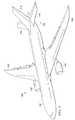
ここで、図面、特に図1を参照すると、例示的な実施形態を実施可能な航空機が示されている。この実施例では、航空機100は、機体106に取り付けられた翼102及び翼104を有する。航空機100は、翼102に取り付けられたエンジン108と、翼104に取り付けられたエンジン110とを含む。 Referring now to the drawings, and in particular to FIG. 1, an aircraft capable of implementing an exemplary embodiment is shown. In this embodiment,
機体106は、尾部112を有している。水平尾翼114、水平尾翼116、及び垂直尾翼118は、機体106の尾部112に取り付けられている。 The
航空機100は、例示的な実施形態に係る、熱可塑性部品が実装される航空機の一例である。例えば、熱可塑性部品は、機体106内の旅客キャビンに配置される。さらに、熱可塑性部品は、組み立て及び製造過程において、水平尾翼116又は水平尾翼114を覆う保護カバーであってもよい。保護カバーは、航空機100の使用前に取り外される。
この航空機100の説明は、様々な例示的な実施形態が実施される1つの環境を説明するために行われている。図1に示す航空機100の説明は、様々な例示的な実施形態を実施する方法に対して構造的限定を加えるものではない。例えば、航空機100は、民間旅客機として示されている。様々な例示的な実施形態は、例えば、自家用機、回転翼機、その他の適切なタイプの航空機等の、他のタイプの航空機に適用することができる。 This description of
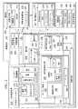
図2は、例示的な実施形態に係る製造環境を示すブロック図である。図2に示すように、製造環境200は、熱可塑性部品が形成される環境の一実施例である。製造環境200は、図1に示す航空機100で用いられる熱可塑性部品が形成される環境の一実施例である。 FIG. 2 is a block diagram illustrating a manufacturing environment according to an exemplary embodiment. As shown in FIG. 2, the
同図に示すように、製造環境200は、アセンブリ201、部品202、構造体204、及びモールド206を含む。いくつかの実施例では、アセンブリ201はモールド206を含む。いくつかの実施例では、 着脱式保護要素210等の着脱式保護要素は、部品202の全て又は一部を覆うことが望ましい。具体的には、着脱式保護要素210等の着脱式保護要素を、部品202の表面208上に配置することが望ましい。着脱式保護要素は、部品202の輸送中又は使用前に部品202の表面が傷つけられたり、他の望まれない欠陥が発生することを防止することができる。輸送後、部品202を使用する前に、着脱式保護要素は取り外される。これらの実施例では、部品202の表面208を覆う着脱式保護要素210を形成するために、構造体204が製造される。着脱式保護要素210は、保護カバー又は保護構造体と呼ばれることもある。部品202の表面208は、外面形状部212を有する。 As shown in the figure, the
これらの実施例では、構造体204は、部品202の外面形状部212に密着するように構成されている。構造体204は、熱可塑性材料214で形成されている。構造体204は、成形体216を有している。構造体204の成形体216は、特異部220を有する内面形状部218を備えている。特異部220は、部品202の表面208における外面形状部212に、構造体204を密着させるように構成されている。構造体204は、本開示の方法にしたがって、熱可塑性シート222で形成されている。構造体204が熱可塑性シート222で形成される実施例では、構造体204の熱可塑性材料214は均一な厚みを有する。いくつかの実施例では、部品202は、熱可塑性部品であることが望ましい。これらの実施例では、部品202は、構造体204からなる。これらの実施例では、部品202は、本開示の方法にしたがって、熱可塑性シート222から製造される。 In these embodiments, the
製造環境200は、構造体204を形成するための機具を含む。同図に示すように、製造環境200は、データベース224と、真空装置226と、加熱装置228と、切断装置230と、デザイン手段280と、形状生成手段282と、成形システム284とを含む。 The
データベース224は、部品202の三次元モデル232を含む。構造体204は、三次元モデル232に基づいて形成される。具体的には、扁平体234は、三次元モデル232に基づいてデザインされる。いくつかの実施例では、デザイン手段280は、部品202の表面208を識別し、部品202の表面208を覆うようにデザインされた構造体204のための扁平体234を作製するように構成されている。 Database 224 includes a three-
扁平体234を熱可塑性シート222から切り取ることにより部分体(portion)236が形成される。扁平体234を有する部分体236をモールド206で成形すると、成形体216を有する構造体204が形成される。成形体216は、三次元モデル232の表面238に基づいている。 A
構造体204が、部品202に用いられる着脱式保護要素210の形態をとる実施例では、成形体216は、表面208を覆うように構成される。表面238は、表面208を三次元でデザインしたものである。この結果、これらの実施例では、成形体216は、表面238を覆うように構成される。これらの実施例では、成形体216の内面形状部218は、構造体204を表面238に密着させる特異部220を有している。着脱式保護要素210は、インジケータ241を有している。インジケータ241は、部品202の使用前に、着脱式保護要素210を取り外すことを知らせるものである。部品202が構造体204で形成される実施例では、成形体216は、表面238と略同一である。例えば、成形体216は、扁平体234をモールド206に固定するために追加されたインデックス部240を有していることを除けば、表面238と同一である。 In embodiments where the
部分体236は、形状生成手段282により形成される。形状生成手段282は、扁平体234を用いて、熱可塑性シート222から部分体236を形成するように構成されている。扁平体234は、切断装置230を用いて、熱可塑性シート222から切り取られる。切断装置230は、少なくとも、切断速度、切断精度、切断エッジ粗度、及び切断時に発生する熱のうち、少なくとも1つに基づいて選択される。切断装置230は、ウォータージェット242の形態をとることができる。ウォータージェット242は、熱可塑性シート222から扁平体234を切り取る処理を、手作業で行うよりも早く行うことができる。他の例において、切断装置230は、レーザーカッター、高温ガスカッター、ルーター加工具(router)、鋸、穿孔具、パンチング機具、切込み具(scoring equipment)、又は他の適切な機具の形態をとる。鋸は、円形鋸、帯鋸、サーベル鋸、ジグソー、又は他の適切な機具の形態をとる。 The
扁平体234は、熱可塑性シート222から切り取られ、構造体204の形状に形成される。したがって、構造体204は、熱可塑性材料214で形成されていることになる。熱可塑性材料214は、特性235を有している。特性235は、例えば、延性、靱性、透過性、耐水性、耐薬品性、抗菌性、保全性、表面密着性、透明度、又は他の所望の特性を含む。いくつかの実施例では、熱可塑性材料214は、Kydex(カイデックス:登録商標)237である。Kydex237は、アクリルとポリ塩化ビニールの合成物質である。Kydex237は、材料の靱性に基づいて選択されてもよい。Kydex237は、材料の延性に基づいて選択されてもよい。いくつかの実施例では、熱可塑性材料214は、アクリロニトリル・ブタジエン・スチレン239である。アクリロニトリル・ブタジエン・スチレン239は、アクリロニトリル、ブタジエン、及びスチレンから形成される。いくつかの実施例では、熱可塑性材料214は、第1熱可塑性材料と呼ばれる。 The
扁平体234を有する部分体236が熱可塑性シート222から切り取られると、部分体236は、モールド206に固定される。部分体236は、部分体236のインデックス部240と、モールド206のインデックス部244とを用いて、モールド206に固定される。いくつかの例では、インデックス部240は、穴246の形態をとる。いくつかの例では、インデックス部244は、穴248の形態をとる。これらの例においては、穴246及び穴248に留め具を通すことにより、扁平体234をモールド206に固定することができる。 When the
成形システム284は、扁平体234を有する熱可塑性シート222を用いて、部品202の表面208を覆うようにデザインされた着脱式保護要素210を形成するように構成されている。いくつかの実施例では、成形システム284は、真空装置226、加熱装置228、及び、モールド206のうち少なくとも1つを含む。 The
真空装置226は、モールド206を真空引きするように構成されている。真空装置226は、真空源、真空バッグ、真空テーブル、シール材、又は他の所望の真空材料を含む。真空装置226は、部分体236がモールド206に固定されている状態で、モールド206及び部分体236を真空引きするために用いられる。 The
加熱装置228は、部分体236及びモールド206を加熱するように構成されている。部分体236がモールド206に固定された状態で、真空下にある部分体236を加熱することにより、モールド206に適合するように部分体236が成形される。具体的には、部分体236は、モールド表面250に適合するように成形され、構造体204として成形される。 The
部分体236及びモールド206は、熱可塑性材料214を軟化させるために十分な温度に達するまで加熱される。部分体236及びモールド206は、モールド206の材料252の融点よりも低い特定の温度に達するまで加熱される。
モールド206は、ベース254及びモールド表面250を有し、材料252の複数の層256で形成されている。材料252は、熱可塑性材料258であってもよい。熱可塑性材料258は、特性260を有するように選択される。特性260は、例えば、強度、剛性、融解温度、材料コスト、及び他の所望の特性を含む。具体的には、熱可塑性材料258は、構造体204の熱可塑性材料214の軟化温度よりも高い融解温度を有するように選択される。また、熱可塑性材料258は、構造体204の熱可塑性材料214の融解温度よりも高い融解温度を有するように選択される。さらに、熱可塑性材料258は、モールド206が付加製造工程(additive manufacturing process)により形成可能なように選択される。いくつかの実施例では、熱可塑性材料258はラテックス262である。いくつかの例では、熱可塑性材料258は、第2熱可塑性材料と呼ばれる。いくつかの実施例では、モールド206は、熱可塑性材料258以外の材料で形成してもよい。 The
モールド206のベース254は、アール264を有するようにデザインされている。アール264は、真空装置226により独立したアールが形成されることを防止するように構成されている。例えば、真空バッグは、面同士の間に交点を有するモールドに対して、独立したアールやしわを形成することがある。 The
モールド表面250は、三次元モデル232の表面238に基づいてデザインされた表面形状部266を有している。表面形状部266は、修正されて、修正表面形状部268となる。モールド206は、修正表面形状部268に基づいて形成されている。 The mold surface 250 has a
修正表面形状部268は、特異部270を有している。特異部270は、修正表面形状部268に配されているが、表面形状部266には配されていない。特異部270が修正表面形状部268に配されることにより、構造体204の成形体216を修正することができる。特異部270が修正表面形状部268に配されることにより、成形処理に影響を与えることができる。例えば、特異部270は、成形後にモールド206から構造体204を取り外し易くする。特異部270は、抜き勾配(draft angle)272及びインデックス部244を含む。インデックス部244は、穴248の形態をとることができる。 The modified surface shape portion 268 has a unique portion 270. The singular part 270 is disposed on the modified surface shape part 268, but is not disposed on the
例えば、抜き勾配272は、モールド206から構造体204を取り外し易くする。抜き勾配272は、構造体204を部品202に密着させるための、内面形状部218の特異部220を形成する。具体的には、抜き勾配272は、部品202の表面208の外面形状部212を内面形状部218が押し付けるように、内面形状部218を形成する。したがって、着脱式保護要素210は、留め具や接着剤を用いることなく、抜き勾配272により部品202に密着する。 For example,
製造環境200は、モールド206を形成するための機具を含む。同図に示すように、製造環境200は、付加製造装置274を含む。モールド206は、付加製造装置274を用いて形成される。従来の機械加工処理では、材料を取り除くことにより構造体を形成する。付加製造処理では、材料を加えることにより構造体を形成する。具体的には、付加製造処理では、連続する個々の層を追加することにより、構造体を形成する。
付加製造装置274は、三次元プリンター、レーザー焼結装置278、又はその他の所望の付加製造装置のうち少なくとも1つの形態をとることができる。 The
1つの実施例では、付加製造装置274は、順次複数の層256を形成することによりモールド206を形成する。複数の層256それぞれの厚みは、付加製造装置274の解像度により異なる。付加製造装置274は、材料252からモールド206を形成する。 In one embodiment, the
付加製造装置274を用いてモールド206を形成することにより、構造体204及びモールド206を所望の時間内で製造することができる。具体的には、いくつかの例では、構造体204及びモールド206は、同じ日に製造することができる。さらに、付加製造装置274を用いてモールド206を形成することにより、従来の金属モールドに比べて製造コストを削減することができる。モールド206は、所望のコスト及び所望の時間内で製造できるため、単回使用の目的でモールド206を作製することができる。 By forming the
次に図3を参照すると、例示的な実施形態に係る、保護カバーの使用が望ましい航空機構造が示されている。航空機構造300は、フランジ302、ボルト304、及び突出部306を有している。同図に示すように、航空機構造300は、航空機の水平尾翼の一部、例えば、図1に示す航空機100の水平尾翼114の一部である。 Referring now to FIG. 3, an aircraft structure is shown in which the use of a protective cover is desirable, according to an exemplary embodiment.
突出部306は、フランジ302内に位置している。航空機構造300が動くと、ボルト304が、突出部306の表面308及び表面310を傷つける可能性がある。この結果、航空機構造300の品質が、所望の品質よりも低下してしまい、交換や手直しが必要になることもある。 The
表面308及び表面310をボルト304から保護するには、突出部306の周辺に、着脱式保護要素を配置することが望ましい。しかしながら、空間312、空間314、及び空間316により、発泡材料やカバー等を含む従来の保護要素は使用できない。さらに、従来の保護要素は、この例においては、破れたり裂けたりし易く、交換が度々必要になるため望ましくない。 In order to protect the
したがって、他のデザインの保護要素が望まれる。さらに、保護要素の形成は、迅速且つ低コストで行われることが望ましい。 Therefore, other design protection elements are desired. Furthermore, it is desirable that the protection element be formed quickly and at low cost.
次に図4を参照すると、例示的な実施形態に係る、保護カバーの使用が望ましい航空機部品が示されている。図示されている航空機部品400は、図3に示される、表面308及び表面310を有する突出部306を含む。また、航空機部品400は、部分402、部分404、及びボルト406を有する。保護カバーにより航空機部品400の表面408を保護することが望ましい。表面408は、突出部306の表面308及び表面310を含む。 Referring now to FIG. 4, an aircraft component is shown in which use of a protective cover is desirable, according to an exemplary embodiment. The illustrated
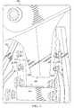
次に図5を参照すると、例示的な実施形態に係るモールドが示されている。モールド500は、図2のブロック形式で示されるモールド206を物理的に実現した例である。この実施例では、モールド500は、図2に示す着脱式保護要素210等の着脱式保護要素を形成するために用いられる。 Referring now to FIG. 5, a mold according to an exemplary embodiment is shown. The
図示のように、モールド500は、図2に示す付加製造装置274等の、付加製造装置により積層された複数の材料層から形成される。モールド500は、図2に示す熱可塑性材料252等の、熱可塑性材料で形成されている。モールド500は、ベース502及びモールド表面504を有している。ベース502は、アール506を有している。アール506は、真空装置により独立したアールが形成されることを防止するように構成されている。例えば、真空バッグは、面同士の間に交点を有するモールドに対して、独立したアールやしわを形成することがある。 As shown, the
モールド表面504は、修正表面形状部508を有している。修正表面形状部508は、インデックス部510を含む。インデックス部510は、この例では、複数の穴512の形態をとる。複数の穴512は、穴514、穴516、穴518、及び穴520を含む。 The
次に図6を参照すると、例示的な実施形態に係るモールドの正面が示されている。具体的には、図6は、図5における方向6−6から見たモールド500を示している。 Referring now to FIG. 6, a front view of a mold according to an exemplary embodiment is shown. Specifically, FIG. 6 shows the
図6から分かるように、修正表面形状部508もまた、抜き勾配602を含んでいる。抜き勾配602は、モールド500の修正表面形状部508のテーパーである。具体的には、モールド500は、抜き勾配602の角度で、幅604から幅606にかけてテーパー状である。抜き勾配602は、モールド500から材料を取り外し易くするように構成されている。さらに、抜き勾配602は、モールド500上において、構造体に特異部を形成するように構成されている。構造体に形成された特異部により、モールド500の形成の基礎となった部品に構造体を密着させることができる。 As can be seen from FIG. 6, the modified
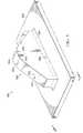
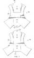
次に図7を参照すると、例示的な実施形態に係る、扁平体を有する2つの部分体が示されている。部分体700及び部分体702は、図2に示す部分体236を具現化したものである。部分体700は、扁平体704を有する。部分体702は、扁平体706を有する。成形後、部分体700及び部分体702は、図2に示す部品202等の部品を覆うための保護カバーを形成する。 Referring now to FIG. 7, two parts having a flat body according to an exemplary embodiment are shown. The
扁平体704は、インデックス部708を有する。インデックス部708は、穴710及び穴712を含む。インデックス部708は、図5に示すモールド500等のモールドに対して扁平体704を固定するために用いられる。穴714は、図2に示すインジケータ241等のインジケータとして機能する。具体的には、穴714は、保護カバーを識別するためのタグ、又は他の構造体を保持するために用いられる。穴714が、タグ又は他の構造を保持するために用いられることにより、オペレータに対して、保護カバーの取り外しを忘れないように注意喚起することができる。 The
扁平体706は、インデックス部716を有する。インデックス部716は、穴718及び穴720を含む。インデックス部716は、図5に示すモールド500等のモールドに対して扁平体706を固定するために用いられる。穴722は、図2に示すインジケータ241等のインジケータとして機能する。具体的には、穴722は、保護カバーを識別するためのタグ、又は他の構造体を保持するために用いられる。穴714が、タグ又は他の構造を保持するために用いられることにより、オペレータに対して、保護カバーの取り外しを忘れないように注意喚起することができる。 The
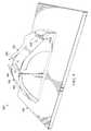
次に図8を参照すると、例示的な実施形態に係るモールドに固定された2つの部分が示されている。図示のように、図7に示す部分体700及び部分体702は、図5に示すモールド500に固定されることにより、アセンブリ800を形成している。部分体700は、留め具802及び留め具804によりモールド500に固定される。留め具802は、部分体700の穴710と、モールド500の穴514とを貫通して配置されている。留め具804は、部分体700の穴712と、モールド500の穴516とを貫通して配置されている。留め具806は、部分体702の穴720と、モールド500の穴518とを貫通して配置されている。留め具808は、部分体702の穴718と、モールド500の穴520とを貫通して配置されている。 Referring now to FIG. 8, two parts secured to a mold according to an exemplary embodiment are shown. As shown, the
部分体700及び部分体702をモールド500に固定した後、図2に示す真空装置226等の真空装置を、アセンブリ800上に配置する。次にアセンブリ800を真空下で加熱して、構造体を形成する。アセンブリ800は、モールド500の熱可塑性材料の融解温度よりも低い特定の温度に達するまで加熱される。アセンブリ800は、部分体700及び部分体702の熱可塑性材料を軟化させるために十分な温度に達するまで加熱される。 After fixing the
次に図9を参照すると、例示的な実施形態に係る、モールドに形成された2つの構造体が示されている。構造体902及び構造体904は、図2に示す構造体204を物理的に実現したものである。構造体902及び構造体904は、部分体700及び部分体702を真空下で加熱することにより形成される。構造体902及び構造体904は、モールド500に対して形成されているため、構造体902及び構造体904は、それぞれモールド表面504に基づいた内面形状部を有している。部品の表面を構造体902及び構造体904で覆うことにより、構造体902及び構造体904は部品の保護カバーの役目を果たす。 Referring now to FIG. 9, two structures formed in a mold are shown, according to an exemplary embodiment. The
図10は、例示的な実施形態に係る、航空機の部品に配置された2つの構造体を示す図である。具体的には、構造体902及び構造体904は、航空機部品400上に配置される。構造体902及び構造体904は、航空機部品400の表面408を覆う着脱式保護要素1002を形成する。構造体902及び構造体904は、構造体902及び構造体904それぞれの形状に基づいて、航空機部品400の表面408に密着する。 FIG. 10 is a diagram illustrating two structures disposed on aircraft components, according to an example embodiment. Specifically,
次に図11を参照すると、例示的な実施形態に係る、熱可塑性部品を形成するための処理フローが示されている。図11に示す処理は、熱可塑性部品を形成するために実行される。いくつかの実施例では、熱可塑性部品は、保護カバーの形態をとる。図11に示す処理は、図2に示す構造体204を形成するために実行される。 Referring now to FIG. 11, a process flow for forming a thermoplastic part according to an exemplary embodiment is shown. The process shown in FIG. 11 is performed to form a thermoplastic part. In some embodiments, the thermoplastic part takes the form of a protective cover. The process shown in FIG. 11 is executed to form the
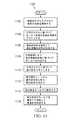
処理を開始すると、まず、部品202の三次元モデル232から、部品202の表面238を識別する(工程1102)。次の処理段階として、三次元モデル232に基づいて、モールド表面250の表面形状部266をデザインする(工程1104)。次の処理段階として、表面形状部266を修正して、修正表面形状部268を形成する(工程1106)。いくつかの実施例では、表面形状部を修正して修正表面形状部を形成すると、加熱時の真空バッグによるアール付けに影響を与える特異部が導入される。これらの実施例では、上記特異部は、図2に示すアール264を含んでいる。いくつかの実施例では、表面形状部を修正して修正表面形状部を形成すると、構造体の内面形状部を縮小する特異部が導入される。これらの実施例では、上記特異部は、図2に示す抜き勾配272を含み、この抜き勾配は、図2に示す内面形状部218に影響を与える。 When the process is started, first, the
次の処理段階として、付加製造により、修正表面形状部268に基づいたモールド206を形成する(工程1108)。例えば、モールド206は、図2に示す付加製造装置274を用いて形成される。いくつかの実施例では、付加製造により修正表面形状部に基づいてモールドを形成する工程は、レーザー焼結を用いて熱可塑性材料からなるモールドを形成することを含み、このモールドは、ベース、アール、及びモールド表面を有する。 As a next processing step, a
次の処理段階として、三次元モデル232に基づいて、扁平体をデザインする(工程1110)。この扁平体は、例えば、図2に示す扁平体234である。図2に示す扁平体234は、三次元モデル232の表面238に基づいてデザインされている。次の処理段階として、熱可塑性シート222から扁平体234を切り取り、部分体を形成する(工程1112)。この部分体は、例えば、熱可塑性シート222から切り取られた、図2に示す部分体236である。次の処理段階として、部分体236をモールド206に固定する(工程1114)。次の処理段階として、部分体236及びモールド206を真空下で加熱することにより、構造体204を形成する(工程1116)。その後、処理を終了する。 As the next processing step, a flat body is designed based on the three-dimensional model 232 (step 1110). This flat body is, for example, the
いくつかの実施例において、構造体を形成した後、この構造体を部品の表面上に配置する。これらの実施例では、構造体は、保護カバーの形態をとる。 In some embodiments, after forming the structure, the structure is placed on the surface of the part. In these embodiments, the structure takes the form of a protective cover.
図12は、例示的な実施形態に係る、熱可塑性部品を形成するための処理フローを示す図である。図12に示す処理は、熱可塑性部品を形成するために実行される。いくつかの実施例では、熱可塑性部品は、保護カバーの形態をとる。図12に示す処理は、例えば、図2に示す構造体204を形成するために実行される。 FIG. 12 is a diagram illustrating a process flow for forming a thermoplastic part, according to an exemplary embodiment. The process shown in FIG. 12 is performed to form a thermoplastic part. In some embodiments, the thermoplastic part takes the form of a protective cover. The process shown in FIG. 12 is executed, for example, to form the
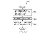
処理を開始すると、まず、三次元モデル232に基づいて、第1熱可塑性材料からなる熱可塑性シート222から、部分体236を切り取る(工程1202)。部分体236は、例えば、図2に示す切断装置230等の所望の切断装置を用いて、熱可塑性シート222から切り取られる。いくつかの例では、部分体236は、図2に示すウォータージェット242等のウォータージェットを用いて切り取ることができる。 When the process is started, first, the
次の処理段階として、部分体236をモールド206に固定する(工程1204)。部分体236は、当該部分体のインデックス部と、モールドのインデックス部とを用いて、モールド206に固定される。いくつかの実施例では、部分体236の穴と、モールド206の穴とに留め具を挿入する。次の処理段階として、部分体236及びモールド206を真空下で加熱することにより、構造体204を形成する(工程1206)。いくつかの実施例では、部分体236及びモールド206を真空下で加熱することにより構造体204を形成する工程は、第2熱可塑性材料の融解温度よりも低い温度であって、且つ、第1熱可塑性材料を軟化させるために十分な温度に達するまで部分体236及びモールド206を加熱することを含む。その後、処理を終了する。 As the next processing step, the
いくつかの実施例において、構造体204を形成した後、構造体204を部品202の表面208上に配置する。これらの例では、構造体204は、部品202の保護カバーを形成する。 In some embodiments, after forming the
本開示の例示的な実施形態を、図13においては航空機の製造及びサービス方法1300に関連させ、図14においては航空機1400に関連させて説明する。まず、図13を参照すると、例示的な実施形態に係る航空機の製造及びサービス方法が、ブロック図の形態で示されている。生産開始前の工程として、航空機の製造及びサービス方法1300は、図14に示した航空機1400の仕様決定及び設計1302と、材料調達1304とを含む。 An exemplary embodiment of the present disclosure is described with reference to aircraft manufacturing and
生産中には、図14に示す航空機1400の部品及び小組立品の製造1306、並びに、システムインテグレーション1308が行われる。その後、図14に示す航空機1400は、認証及び納品1310の工程を経て、使用1312に入る。顧客による使用1312中は、図14の航空機1400は、定例のメンテナンス及びサービス1314に組み込まれる。このサービスは、調整、変更、改修、及び他のメンテナンス又はサービスを含み得る。 During production, part 1 and
航空機の製造及びサービス方法1300の各工程は、システムインテグレーター、第三者、オペレーター、又はこれらの組み合わせによって実行又は実施することができる。これらの例において、オペレーターは顧客であってもよい。説明のために言及すると、システムインテグレーターは、航空機メーカー及び主要システム下請業者をいくつ含んでいてもよいが、これに限定されない。第三者は、売主、下請業者、供給業者をいくつ含んでいてもよいが、これに限定されない。オペレーターは、航空会社、リース会社、軍事団体、サービス組織等であってもよい。 The steps of aircraft manufacturing and
図14を参照して説明すると、例示的な実施形態を実施可能な航空機がブロック図で示されている。この例において、航空機1400は、図13に示した航空機の製造及びサービス方法1300によって生産され、複数のシステム1404及び内装1406を備えた機体1402を含み得る。システム1404の例には、1又はそれ以上の推進系1408、電気系1410、油圧系1412、及び環境系1414が含まれる。また、その他のシステムをいくつ含んでいてもよい。また、航空宇宙産業に用いた場合を例として示しているが、種々の例示的な実施形態を、例えば自動車産業等の他の産業に適用してもよい。 Referring to FIG. 14, an aircraft capable of implementing an exemplary embodiment is shown in block diagram form. In this example,
本明細書において実施される装置及び方法は、図13に示した航空機の製造及びサービス方法1300おける、少なくとも1つの段階において、採用することができる。さらに、本明細書において実施される装置及び方法は、図14に示した航空機1400の一部を形成するために採用することができる。例えば、1以上の例示的な実施形態は、機体1402の一部又は航空機1400の内装1406を形成するために用いられてもよい。 The apparatus and method implemented herein may be employed in at least one stage in the aircraft manufacturing and
1つ又はそれ以上の例示的な実施形態は、部品及び小組立品の製造1306と、システムインテグレーション1308と、認証及び納品1310と、メンテナンス及びサービス1314とのうち少なくとも1つの段階において、用いられてもよい。例えば、1つ又はそれ以上の例示的な実施形態は、部品及び小組立品の製造1306の工程中に用いられてもよい。構造体204が図2に示す部品202である場合、部品202は、部品及び小組立品の製造1306の工程中に用いられてもよい。具体的に、部品202は、例えば荷物棚カバー又は肘掛け等の航空機の内装の一部であってもよい。さらに、メンテナンス及びサービス1314の工程中に交換作業を行うために、構造体204を用いてもよい。例えば、航空機1400の定期的なメンテナンス中に部品交換を行うために、構造体204を着脱式保護要素210として用いることにより、部品202を保護してもよい。 One or more exemplary embodiments may be used in at least one of the following stages: parts and
付加製造によりモールドを形成することで、このモールドは所望の特性を有することができる。具体的には、付加製造を用いることで、所望の価格で所望の時間内にモールドを形成することができる。したがって、付加製造を用いることにより、コスト効率の良い、単回使用の成形を行うことが可能になる。 By forming the mold by additive manufacturing, the mold can have desired characteristics. Specifically, the mold can be formed at a desired price and in a desired time by using additive manufacturing. Therefore, by using additive manufacturing, it is possible to perform cost-effective single-use molding.
モールド上に構造体を形成することで、この構造体は所望の特性を有することができる。モールド上に構造体を形成することで、熱可塑性シート222の特性が保持される。さらに、モールド上に構造体を形成することで、この構造体を所望の時間内に形成することができる。 By forming the structure on the mold, the structure can have desired characteristics. By forming the structure on the mold, the characteristics of the thermoplastic sheet 222 are maintained. Furthermore, the structure can be formed within a desired time by forming the structure on the mold.
付加製造装置274を用いてモールド206を形成することで、例えば、引き抜き、押し出し、又は金属製モールドを用いた成形等の従来の方法よりも少ない資源を用いて構造体204を製造することができる。例えば、付加製造装置274を用いてモールド206を形成することにより、より短時間で構造体204を製造することができる。さらに、付加製造装置274を用いてモールド206を形成することにより、より低い成形型コストで構造体204を製造することができる。したがって、所望の特性を有した熱可塑性部品を、所望の時間内且つ所望のコストで製造することができる。 By forming the
特異部220を有する内面形状部218を備えるように構造体204を形成することにより、構造体204は着脱式保護要素210の役目を果たすことができる。着脱式保護要素210は、接着剤や留め具を用いることなく、特異部220を用いて部品202の表面208に密着する。着脱式保護要素210は、輸送中に部品202を破損から守り、部品202の使用前に取り外される。着脱式保護要素210は、従来の保護用着脱式機具ほど場所をとることなく、部品を保護することができる。 By forming the
様々な例示的な実施形態の説明は、例示及び説明のために提示したものであり、全てを網羅することや、開示した形態での実施に限定することを意図するものではない。多くの変形又は変更が当業者には明らかであろう。さらに、例示的な実施形態は、他の例示的な実施形態とは異なる特徴をもたらす場合がある。選択した実施形態は、実施形態の原理及び実際の用途を最も的確に説明するために、且つ、当業者が、想定した特定の用途に適した種々の変形を加えた様々な実施形態のための開示を理解できるようにするために、選択且つ記載したものである。 The description of the various exemplary embodiments is presented for purposes of illustration and description, and is not intended to be exhaustive or limited to implementation in the form disclosed. Many variations or modifications will be apparent to those skilled in the art. Further, the exemplary embodiments may provide different features than other exemplary embodiments. The selected embodiment is intended to best explain the principles and practical application of the embodiment, and for those skilled in the art to make various modifications suitable for the particular application envisioned by those skilled in the art. It has been chosen and described in order to provide an understanding of the disclosure.
Claims (15)
Translated fromJapanese前記部分体をモールドに固定することと、
前記部分体及び前記モールドを真空下で加熱して構造体を形成すること、とを含む方法。Based on the three-dimensional model, cutting a partial body from the thermoplastic sheet made of the first thermoplastic material;
Fixing the partial body to a mold;
Heating the partial body and the mold under vacuum to form a structure.
前記三次元モデルに基づいて、モールド表面の表面形状部をデザインすることと、
前記表面形状部を修正して、修正表面形状部を形成すること、とをさらに含む請求項6に記載の方法。Identifying the surface of the part from the three-dimensional model;
Based on the three-dimensional model, designing a surface shape portion of the mold surface;
7. The method of claim 6, further comprising modifying the surface feature to form a modified surface feature.
Applications Claiming Priority (2)
| Application Number | Priority Date | Filing Date | Title |
|---|---|---|---|
| US14/182,649 | 2014-02-18 | ||
| US14/182,649US9844904B2 (en) | 2014-02-18 | 2014-02-18 | Formation of thermoplastic parts |
Related Child Applications (1)
| Application Number | Title | Priority Date | Filing Date |
|---|---|---|---|
| JP2019087968ADivisionJP6763058B2 (en) | 2014-02-18 | 2019-05-08 | Formation of thermoplastic parts |
Publications (1)
| Publication Number | Publication Date |
|---|---|
| JP2015150892Atrue JP2015150892A (en) | 2015-08-24 |
Family
ID=52577609
Family Applications (2)
| Application Number | Title | Priority Date | Filing Date |
|---|---|---|---|
| JP2015020905APendingJP2015150892A (en) | 2014-02-18 | 2015-02-05 | formation of thermoplastic parts |
| JP2019087968AActiveJP6763058B2 (en) | 2014-02-18 | 2019-05-08 | Formation of thermoplastic parts |
Family Applications After (1)
| Application Number | Title | Priority Date | Filing Date |
|---|---|---|---|
| JP2019087968AActiveJP6763058B2 (en) | 2014-02-18 | 2019-05-08 | Formation of thermoplastic parts |
Country Status (8)
| Country | Link |
|---|---|
| US (2) | US9844904B2 (en) |
| EP (1) | EP2907650B1 (en) |
| JP (2) | JP2015150892A (en) |
| CN (2) | CN110877451B (en) |
| CA (1) | CA2876170C (en) |
| ES (1) | ES2676595T3 (en) |
| PT (1) | PT2907650T (en) |
| TR (1) | TR201807083T4 (en) |
Families Citing this family (5)
| Publication number | Priority date | Publication date | Assignee | Title |
|---|---|---|---|---|
| US9844904B2 (en) | 2014-02-18 | 2017-12-19 | The Boeing Company | Formation of thermoplastic parts |
| GB201600946D0 (en)* | 2016-01-19 | 2016-03-02 | Eejay Bv | Moulding process |
| US11084195B2 (en)* | 2016-05-27 | 2021-08-10 | Husky Injection Molding Systems Ltd. | Mold gate structures |
| US10300660B2 (en)* | 2016-10-25 | 2019-05-28 | Covestro Deutschland Ag | Method of treating at least part of the surface of a 3D-printed article |
| SG11202004522RA (en)* | 2017-11-27 | 2020-06-29 | Essentium Inc | Tool assembly for manufacturing parts and a method of producing a tooling assembly |
Citations (5)
| Publication number | Priority date | Publication date | Assignee | Title |
|---|---|---|---|---|
| US4751121A (en)* | 1985-05-28 | 1988-06-14 | Huels Troisdorf Aktiengesellschaft | Multi-ply self-adhesive and deep-drawable protective sheet, especially for automotive vehicles |
| US5255875A (en)* | 1992-04-30 | 1993-10-26 | The United States Of America As Represented By The Secretary Of The Army | Protective hardside covers for vehicle surfaces |
| JP2001079934A (en)* | 1999-09-13 | 2001-03-27 | Honda Motor Co Ltd | Vacuum forming mold |
| US20100102476A1 (en)* | 2008-10-29 | 2010-04-29 | Higgins Michael H | Method for manufacturing raised relief maps |
| JP2012511467A (en)* | 2008-12-11 | 2012-05-24 | ビ−エイイ− システムズ パブリック リミテッド カンパニ− | Protecting aircraft transparency |
Family Cites Families (15)
| Publication number | Priority date | Publication date | Assignee | Title |
|---|---|---|---|---|
| CA694479A (en)* | 1964-09-15 | The B. F. Goodrich Company | Apparatus for and method of making electrically heated means for a surface | |
| US6287428B1 (en)* | 1999-08-30 | 2001-09-11 | Regale Corporation | Mold with integral screen and method for making mold and apparatus and method for using the mold |
| CA2538358A1 (en)* | 2003-09-11 | 2005-03-24 | The Ex One Company | Layered manufactured articles having small-width fluid conduction vents and methods of making same |
| US20070029698A1 (en)* | 2003-09-11 | 2007-02-08 | Rynerson Michael L | Layered manufactured articles having small-diameter fluid conduction vents and method of making same |
| CN1289278C (en)* | 2003-12-09 | 2006-12-13 | 西北工业大学 | Method for determining blanks for plate forming members |
| EP1773559A1 (en)* | 2004-06-28 | 2007-04-18 | Ex One Corporation | Gas permeable molds |
| KR20080064155A (en)* | 2005-10-14 | 2008-07-08 | 어플라이드 리써치 어쏘시에이츠 뉴질랜드 리미티드 | Method and apparatus for monitoring surface features |
| US20070241021A1 (en) | 2006-04-12 | 2007-10-18 | Nokia Corporation | Thermoformed cover for electronic device and method for forming |
| CN101650756A (en)* | 2009-08-26 | 2010-02-17 | 成都飞机工业(集团)有限责任公司 | Skinning method of multi-point forming plane |
| US20110108667A1 (en)* | 2009-11-12 | 2011-05-12 | Hans-Peter Keller | Thermoplastic Composite Window Panel for Aircraft Applications |
| CN102069247B (en)* | 2010-12-16 | 2012-02-29 | 沈阳黎明航空发动机(集团)有限责任公司 | A tenon anti-corrosion method in electrolytic machining of blades |
| CN102582091B (en)* | 2012-01-05 | 2015-09-30 | 中国商用飞机有限责任公司 | Spherical frame of airplane body and manufacturing method thereof |
| CN102825428B (en)* | 2012-08-19 | 2015-02-04 | 什邡市明日宇航工业股份有限公司 | Aircraft fairing and method for manufacturing same |
| CN103331570A (en)* | 2013-06-29 | 2013-10-02 | 四川海普工控技术有限公司 | Technical method for machining metal plate |
| US9844904B2 (en) | 2014-02-18 | 2017-12-19 | The Boeing Company | Formation of thermoplastic parts |
- 2014
- 2014-02-18USUS14/182,649patent/US9844904B2/enactiveActive
- 2014-12-30CACA2876170Apatent/CA2876170C/enactiveActive
- 2015
- 2015-02-04PTPT151538055Tpatent/PT2907650T/enunknown
- 2015-02-04ESES15153805.5Tpatent/ES2676595T3/enactiveActive
- 2015-02-04EPEP15153805.5Apatent/EP2907650B1/enactiveActive
- 2015-02-04TRTR2018/07083Tpatent/TR201807083T4/enunknown
- 2015-02-05JPJP2015020905Apatent/JP2015150892A/enactivePending
- 2015-02-06CNCN201911075996.1Apatent/CN110877451B/enactiveActive
- 2015-02-06CNCN201510064628.2Apatent/CN104842547B/enactiveActive
- 2017
- 2017-08-17USUS15/679,842patent/US10300653B2/enactiveActive
- 2019
- 2019-05-08JPJP2019087968Apatent/JP6763058B2/enactiveActive
Patent Citations (5)
| Publication number | Priority date | Publication date | Assignee | Title |
|---|---|---|---|---|
| US4751121A (en)* | 1985-05-28 | 1988-06-14 | Huels Troisdorf Aktiengesellschaft | Multi-ply self-adhesive and deep-drawable protective sheet, especially for automotive vehicles |
| US5255875A (en)* | 1992-04-30 | 1993-10-26 | The United States Of America As Represented By The Secretary Of The Army | Protective hardside covers for vehicle surfaces |
| JP2001079934A (en)* | 1999-09-13 | 2001-03-27 | Honda Motor Co Ltd | Vacuum forming mold |
| US20100102476A1 (en)* | 2008-10-29 | 2010-04-29 | Higgins Michael H | Method for manufacturing raised relief maps |
| JP2012511467A (en)* | 2008-12-11 | 2012-05-24 | ビ−エイイ− システムズ パブリック リミテッド カンパニ− | Protecting aircraft transparency |
Also Published As
| Publication number | Publication date |
|---|---|
| CN104842547A (en) | 2015-08-19 |
| US20150231818A1 (en) | 2015-08-20 |
| CN110877451B (en) | 2021-06-18 |
| CA2876170C (en) | 2018-08-14 |
| JP2019166837A (en) | 2019-10-03 |
| EP2907650B1 (en) | 2018-04-11 |
| US20170341289A1 (en) | 2017-11-30 |
| TR201807083T4 (en) | 2018-06-21 |
| EP2907650A1 (en) | 2015-08-19 |
| CA2876170A1 (en) | 2015-08-18 |
| CN110877451A (en) | 2020-03-13 |
| JP6763058B2 (en) | 2020-09-30 |
| US10300653B2 (en) | 2019-05-28 |
| ES2676595T3 (en) | 2018-07-23 |
| PT2907650T (en) | 2018-05-15 |
| CN104842547B (en) | 2019-12-24 |
| US9844904B2 (en) | 2017-12-19 |
Similar Documents
| Publication | Publication Date | Title |
|---|---|---|
| JP6763058B2 (en) | Formation of thermoplastic parts | |
| US10081140B2 (en) | Apparatus for and method of compaction of a prepreg | |
| JP6558940B2 (en) | Method and apparatus for layup tooling | |
| EP2907652B1 (en) | Composite filler | |
| US20090071217A1 (en) | Composite Fabrication Apparatus and Method | |
| BR102016026894A2 (en) | method and system for forming a thermoplastic part, and forming press | |
| US10647406B2 (en) | Closed-angle composite airfoil spar and method of fabricating the same | |
| EP2982500B1 (en) | Composite structure and method of forming thereof | |
| US10518489B2 (en) | Composite structures incorporating additive manufactured components | |
| EP4234219B1 (en) | Structural rework of cellular core panels | |
| EP2897780B1 (en) | Method of forming a tube from a thermoplastic sandwich sheet | |
| EP2744641B1 (en) | Compression molding of composite material quasi-isotropic flakes | |
| EP3274145B1 (en) | Processes for manufacturing parts employing additive manufacturing | |
| US11865795B2 (en) | Method and system for producing an at least two-layer composite serving as a lining for a vehicle interior component | |
| EP3508343A1 (en) | Thermoplastic composite laminate with ultraviolet protection and method of forming the same | |
| EP3686105B1 (en) | Systems and methods for aircraft structure surface covers | |
| US9862164B2 (en) | Process or system to reduce cost and weight of aerospace interior structural thermoplastic or composite panel constructions | |
| US20250236382A1 (en) | Integrated stringer panel and method of making thereof | |
| WO2025207263A1 (en) | Composite components manufacturing and methods thereof | |
| Bitzer | Honeycomb processes | |
| US20160129681A1 (en) | Method for producing composite workpieces |
Legal Events
| Date | Code | Title | Description |
|---|---|---|---|
| A621 | Written request for application examination | Free format text:JAPANESE INTERMEDIATE CODE: A621 Effective date:20180122 | |
| A131 | Notification of reasons for refusal | Free format text:JAPANESE INTERMEDIATE CODE: A131 Effective date:20181211 | |
| A601 | Written request for extension of time | Free format text:JAPANESE INTERMEDIATE CODE: A601 Effective date:20190308 | |
| A02 | Decision of refusal | Free format text:JAPANESE INTERMEDIATE CODE: A02 Effective date:20190716 |