JP2015150625A - Mechanism arm - Google Patents
Mechanism armDownload PDFInfo
- Publication number
- JP2015150625A JP2015150625AJP2014024514AJP2014024514AJP2015150625AJP 2015150625 AJP2015150625 AJP 2015150625AJP 2014024514 AJP2014024514 AJP 2014024514AJP 2014024514 AJP2014024514 AJP 2014024514AJP 2015150625 AJP2015150625 AJP 2015150625A
- Authority
- JP
- Japan
- Prior art keywords
- rod
- proportional
- virtual axis
- wheel
- curved
- Prior art date
- Legal status (The legal status is an assumption and is not a legal conclusion. Google has not performed a legal analysis and makes no representation as to the accuracy of the status listed.)
- Granted
Links
- 238000005452bendingMethods0.000claimsdescription44
- 230000008878couplingEffects0.000claimsdescription12
- 238000010168coupling processMethods0.000claimsdescription12
- 238000005859coupling reactionMethods0.000claimsdescription12
- BALXUFOVQVENIU-KXNXZCPBSA-Npseudoephedrine hydrochlorideChemical compound[H+].[Cl-].CN[C@@H](C)[C@@H](O)C1=CC=CC=C1BALXUFOVQVENIU-KXNXZCPBSA-N0.000abstract1
- 230000005540biological transmissionEffects0.000description7
- 229910000831SteelInorganic materials0.000description2
- 230000002093peripheral effectEffects0.000description2
- 239000010959steelSubstances0.000description2
- 238000000034methodMethods0.000description1
- 238000006467substitution reactionMethods0.000description1
Images


Landscapes
- Manipulator (AREA)
Abstract
Description
Translated fromJapanese本発明は、機械アームに関し、特に同一の回転中心を有する連接棒式機械アームに関する。 The present invention relates to a mechanical arm, and more particularly to a connecting rod type mechanical arm having the same rotation center.
特許文献1に記載の発明では、同一の回転中心を有する五連接棒機構を採用する機械アームを提供している。この機械アームは、四つの互いに連接される湾曲棒を含む。全ての湾曲棒の両端の回転中心は、同じ回転中心を通過する。機械アームは、主に非侵襲的な手術システムに使われ、超小型手術器械を取り付けることができ、且つ超小型手術器械の揺動方向及び角度を極めて正確に制御することができる。 The invention described in
しかしながら、前述の機械アームは、少なくとも四つの湾曲棒を含むため、相当な体積を有する。通常、非侵襲的な手術システムは、多数の機械アームを含み、これらの機械アームによって、異なる功能を備える多数の超小型手術器械を取り付けることができる。従って、相当に限られた手術空間において、機械アームの体積の減少は、非侵襲的な手術システムの空間の配置に有利であり、且つ医務員に障害をもたらすことを避けることができる。 However, the aforementioned mechanical arm has a substantial volume because it includes at least four curved bars. Typically, a non-invasive surgical system includes a number of mechanical arms by which a number of microsurgical instruments with different capabilities can be attached. Thus, in a fairly limited surgical space, the reduction of the volume of the mechanical arm is advantageous for the space arrangement of the non-invasive surgical system and avoids disturbing medical personnel.
また、前述の機械アームの中に、湾曲棒の作動が互いに制限され、且つ湾曲棒を駆動し回転させる駆動装置が空間の制限を受けるため、各湾曲棒の回転角度が制限されている。よって、機械アームは、超小型手術器械を動かし、相当に限られている作業区間で作動する。 In addition, in the above-described mechanical arm, the operation of the bending rods is restricted to each other, and the drive device that drives and rotates the bending rods is limited in space, so that the rotation angle of each bending rod is limited. Thus, the mechanical arm moves the microsurgical instrument and operates in a fairly limited working section.
上述の欠点に対し、本発明の主な目的は、より小さい体積を有し、操作員に障害を与えることなく、より大きな作業区間を提供可能な機械アームを提供することにある。 In contrast to the above-mentioned drawbacks, the main object of the present invention is to provide a machine arm that has a smaller volume and can provide a larger working section without disturbing the operator.
上述の目的を達成するために、本発明の機械アームは、第一湾曲棒、第一比例輪、第二湾曲棒、第二比例輪、第一可撓性ロープ、結合棒、第三比例輪及び第二撓性ロープを備える。第一湾曲棒は、両端に第一枢接部及び第二枢接部を有し、第一枢接部及び第二枢接部を通す直線をそれぞれ第一仮想軸線及び第二仮想軸線と定義し、第一仮想軸線と第二仮想軸線とが所定の回転中心で交わり、第一駆動ユニットに駆動され、第一仮想軸線を回転軸として回転する。第一比例輪は、回転中心を通す直線を第三仮想軸線と定義し、第二駆動ユニットに駆動され、第三仮想軸線を回転軸として回転可能である。第二湾曲棒は、両端に第三枢接部及び第四枢接部を有し、第四枢接部及び回転中心を通す直線を第四仮想軸線と定義し、第三枢接部が第一湾曲棒の第二枢接部に枢接されている。第二比例輪は、第二湾曲棒の第三枢接部に固定され、第一湾曲棒の第二枢接部に枢接されている。第一可撓性ロープは、第一比例輪と第二比例輪に繞設され、第二湾曲棒に固定され、第一比例輪が回転する時、第二比例輪及び第二湾曲棒を動かし、第二仮想軸線を回転軸として第二比例輪及び第二湾曲棒を回転させる。結合棒及び第三比例輪は、互いに固定され、且つ第二湾曲棒の第四枢接部に枢接されている。第二可撓性ロープは、第二比例輪及び第三比例輪に繞設され、第一湾曲棒に固定され、第二比例輪が回転する時、第三比例輪及び結合棒を動かし、第四仮想軸線を回転軸として第三比例輪及び結合棒を回転させる。 In order to achieve the above object, the mechanical arm of the present invention includes a first curved rod, a first proportional wheel, a second curved rod, a second proportional wheel, a first flexible rope, a coupling rod, and a third proportional wheel. And a second flexible rope. The first bending rod has a first pivot part and a second pivot part at both ends, and straight lines passing through the first pivot part and the second pivot part are defined as a first virtual axis and a second virtual axis, respectively. Then, the first virtual axis and the second virtual axis intersect at a predetermined center of rotation, and are driven by the first drive unit to rotate about the first virtual axis. The first proportional wheel defines a straight line passing through the rotation center as a third virtual axis, is driven by the second drive unit, and can rotate about the third virtual axis as a rotation axis. The second bending rod has a third pivot part and a fourth pivot part at both ends, a straight line passing through the fourth pivot part and the rotation center is defined as a fourth virtual axis, and the third pivot part is the first pivot part. It is pivotally connected to the second pivot of the curved bar. The second proportional wheel is fixed to the third pivot portion of the second curved rod and pivoted to the second pivot portion of the first curved rod. The first flexible rope is installed on the first proportional wheel and the second proportional wheel and is fixed to the second curved rod, and when the first proportional wheel rotates, the second proportional wheel and the second curved rod are moved. The second proportional wheel and the second bending rod are rotated about the second virtual axis as the rotation axis. The connecting rod and the third proportional wheel are fixed to each other and pivoted to the fourth pivoting portion of the second curved rod. The second flexible rope is installed on the second proportional wheel and the third proportional wheel, and is fixed to the first curved rod. When the second proportional wheel rotates, the third proportional wheel and the coupling rod move, The third proportional wheel and the connecting rod are rotated about the four virtual axes.
よって、機械アームは、結合棒に器械を取り付けるために使われ、器械を極めて正確に制御することができ、器械が回転中心を回転し揺動するようにする。また、同じ功能を持つ常用の機械アームと比較する時、本発明の機械アームは、湾曲棒の数が少ないため、体積が小さいことで、操作員が作業するためのより大きい空間を形成可能であり、各湾曲棒の回転角度が制限されていない。よって、機械アームは、操作員が障害なく操作するようにし、より大きな作業区間を提供することができる。 Thus, the mechanical arm is used to attach the instrument to the connecting rod, allowing the instrument to be controlled with great precision and allowing the instrument to rotate and oscillate about its center of rotation. In addition, when compared with a regular mechanical arm having the same function, the mechanical arm of the present invention has a small number of curved rods, so that a small volume can form a larger space for an operator to work. Yes, the rotation angle of each curved bar is not limited. Therefore, the machine arm can be operated without an obstacle by an operator and can provide a larger work section.
本発明による機械アームの詳細な構造、特徴、取り付け、あるいは使用方式は、後述の実施方式に詳細に説明されている。しかしながら、本発明の分野に一般的な知識を持つ人は、詳細な説明及び本発明に挙げられている実施形態が本発明を説明するためであり、本発明の特許請求の範囲を制限することではないことを理解するはずである。 The detailed structure, features, mounting, or usage of the mechanical arm according to the present invention is described in detail in the implementation method described below. However, one of ordinary skill in the art of the present invention is intended to explain the present invention by the detailed description and the embodiments listed in the present invention, and limit the scope of the claims of the present invention. You should understand that it is not.
先ず、ここに出願人が説明しなければならないのは、以下に紹介された実施形態及び図面の中に、同じ参考番号が同じ、あるいは類似の部材、あるいは構造特徴を表示することである。部材が他部材の上に設置されているのは、前述の部材が直接に、あるいは間接に他部材の上に設置されていることを意味している。つまり、二つの部材の間に、一つあるいは多数の他部材が設置されている。 First of all, the applicant has to explain that the same reference numbers indicate the same or similar members or structural features in the embodiments and drawings introduced below. The fact that the member is installed on the other member means that the aforementioned member is installed directly or indirectly on the other member. That is, one or many other members are installed between the two members.
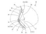
図1〜図4を参考する。本発明の一実施形態による機械アーム10は、同一の回転中心を有する連接棒式機械アームであり、駆動装置20及び同一の回転中心を有する駆動装置30を備える。 Please refer to FIG. A
ここで、「同一の回転中心を有する連接棒式機械アーム」及び「同一の回転中心を有する駆動装置」の「同一の回転中心を有する」とは、全ての回転可能な部位の回転軸の中心(つまり、後述の第一仮想軸線L1、第二仮想軸線L2、第三仮想軸線L3、第四仮想軸線L4)が回転中心C(center of spherical rotation)で交わることを意味する。よって、作動時において、各回転可能な部位が回転中心Cを中心にする仮想の球面で移動すると考えられる。 Here, “connecting rod type mechanical arm having the same center of rotation” and “driving device having the same center of rotation” “having the same center of rotation” means the center of the rotation axis of all rotatable parts. (That is, it means that a first virtual axis L1, a second virtual axis L2, a third virtual axis L3, and a fourth virtual axis L4, which will be described later) intersect at a rotation center C (center of spherical rotation). Therefore, it is considered that each rotatable part moves on a virtual spherical surface centered on the rotation center C during operation.
機械アーム10は、駆動装置30に器械装置を設置するために使われる(図に示さない)。器械装置は、特定功能を持つ器械、たとえば、超小型手術器械を含む。また、通常、回転中心Cを指す、あるいは通過するよう器械が設置されている。駆動装置30は、器械装置を動かし、器械装置が実質的に回転中心Cを中心として回転するようにし、器械の揺動方向及び角度を正確に制御することができる。機械アーム10の構造を、以下に詳細に述べる。 The
駆動装置20は、固定座22、固定座20に設置されている第一駆動ユニット24及び第二駆動ユニット26を含む。第一駆動ユニット24は、モータ(図に示さない)、モータが出力した回転運動エネルギーを駆動装置30に伝達できる両プーリー244、245、及びベルト246を含む。第二駆動ユニット26は、モータ262、モータ262が出力した回転運動エネルギーを駆動装置30に伝達できる伝動輪264を含む。 The drive device 20 includes a
駆動装置30は、第一湾曲棒31、第一比例輪32、第二湾曲棒34、結合棒35、第三比例棒36、第一可撓性ロープ37及び第二可撓性ロープ38を含む。 The
第一湾曲棒31は、同調で作動する二つの棒部材31A、31B、及び一つの棒部材31Aに設置されている張力調整装置31Cを含む。各棒部材31A、31Bの両端は、それぞれ第一枢接部311及び第二枢接部312を有する。二つの第一枢接部311を通過する直線を第一仮想軸線L1と定義し、二つの第二枢接部312を通過する直線を第二仮想軸線L2と定義することができる。第一仮想軸線L1は、第二仮想軸線L2と回転中心Cで交わる。二つの第一枢接部311は、第一駆動ユニット24のプーリー245と同軸に設置され、プーリーにより動かされ、回転する。つまり、第一湾曲棒31は、第一駆動ユニット24に駆動され、第一仮想軸線L1を回転軸心として回転する。 The first
第一比例輪32は、第一湾曲棒31の二つの棒部材31Aと31Bの間に設けられている。第一比例輪32には、回転中心Cを通過する直線である第三仮想軸線L3が定義されている。本実施形態に、第一比例輪32は、第一湾曲棒31の第一枢接部311と同軸に設置されている。よって、第三仮想軸線L3は、第一仮想軸線L1と重なる。しかしながら、第一比例輪32と第一湾曲棒31の第一枢接部311とを同軸に設置しなくてもよいため、第三仮想軸線L3は、第一仮想軸線L1と重ならない。第5図に示している。 The first
第二湾曲棒33は、第一湾曲棒31の二つの棒部材31Aと31Bの間に設置されている棒部材33A及び棒部材33Aに設置されている張力調整装置33Bを含む。棒部材33Aの両端は、それぞれ第三枢接部331及び第四枢接部332を有する。第三枢接部331は、第一湾曲棒31の第二枢接部312に枢接され、且つ第二枢接部312対して、第二仮想軸線L2を回転軸心として回転することができる。第二湾曲棒33は、第四枢接部332を通過する直線を第四仮想軸線L4と定義することができる。また、第四仮想軸線L4は、回転中心Cを通過する。 The second
第二比例輪34は、第一湾曲棒31の二つの棒部材31Aと31Bの間に設けられ、第二湾曲棒33の第三枢接部331を通過する。第二比例輪34は、第一湾曲棒31の第二枢接部312に枢接され、且つ第二湾曲棒33の第三枢接部331に固定されるため、第三枢接部331と同調で回転することができる。 The second
結合棒35の両端は、第五枢接部351及び取り付け部352を有する。第五枢接部351は、第二湾曲棒33の第四枢接部332に枢接され、且つ第四枢接部332を相対し、第四仮想軸線L4を中心に回転することができる。取り付け部352は、器械装置と連接するために使われている。 Both ends of the connecting
第三比例輪36は、第二湾曲棒33の第四枢接部332に枢接され、第四枢接部332と結合棒35の第五枢接部351の間に位置されている。また、第三比例輪36は、第五枢接部351に固定されているため、第五枢接部351と同調で回転することができる。 The third
各可撓性ロープ37,38は、鋼索(限らない)でもよい。第一可撓性ロープ37は、第二駆動装置26の264、第一比例輪32及び第二比例輪34に繞設され、第二湾曲棒33の張力調整装置33Bに固定されている。第二可撓性ロープ38は、第二比例輪34及び第三比例輪36に繞設され、第一湾曲棒31の張力調整装置31Cに固定されている。伝動輪264がモータ262に駆動され、回転する時に、第一可撓性ロープ37は、伝動輪264とともに回転し、第一比例輪32を動かし回転させ、且つ第二比例輪34及び第二湾曲棒33を動かし第二仮想軸線L2を中心に回転させる。同時に、第二可撓性ロープ38は、第二比例輪34と一緒に回転し、第三比例輪36及び結合棒35を動かし第四仮想軸線L4を中心に回転させる。また、等比例輪32、34、36の回転角度は、これらの外径の比率によって、特定的な比例関係を有する。従って、第二駆動ユニット26により第一比例輪32の回転角度を制御することによって、第二湾曲棒33及び結合棒35の回転角度を制御することができる。 Each
使用者が両張力調整装置31C、33Bによって、第二可撓性ロープ38及び第一可撓性ロープ37の張力を調整することができる。第一湾曲棒31及び第二湾曲棒33に、張力調整装置31C,33Bが設けなくてもよいため、可撓性ロープ37,38は、棒部材33A及び31Aに固定されている。 The user can adjust the tension of the second
本実施形態に、第一湾曲棒31の長さは、実質的に第二湾曲棒33の長さと同じである。第一比例輪32の外径は、第三比例輪36の外径に等しく、且つ第二比例輪34の外径の二倍である。つまり、第一、二、三比例輪の外径の比率は、2:1:2である。よって、結合棒35がどんな状況であっても、第五枢接部351が第一湾曲棒31の第一枢接部311に向く一方、取り付け部352が第一枢接部311から離れる方向に向く。従って、器械装置と駆動装置30、あるいは駆動装置20との間の互いの衝突を避けることができ、駆動装置30の制御方程式の計算を簡単にすることができる。しかしながら、本発明による機械アームは、前述に限らない特徴を有する。 In the present embodiment, the length of the first
本発明の「第一湾曲棒の長さは、実質的に第二湾曲棒の長さと同じである」の中で、第一湾曲棒31の長さは、第一、二枢接部311,312が位置する仮想球面上の第一、二仮想軸線L1,L2間の距離と定義されている。つまり、第一湾曲棒31の長さは、第一、二枢接部311、312の中心点が位置する仮想球面上において、第一、二枢接部311、312の中心点により形成された弧線の長さを指す。同様に、第二湾曲棒33の長さは、第三、四枢接部331,332が位置する仮想球面上の第二、四仮想軸線L2,L4間の距離と定義されている。つまり、第二湾曲棒33の長さは、第三、四枢接部331、332の中心点が位置する仮想球面上において、第三、四枢接部331、332の中心点により形成された弧線の長さを指す。また、本発明で述べた第一、二、三比例輪32,34,36の外径は、可撓性ロープ37,38が各比例輪32,34,36に巻きつく外周面の曲率の半径と定義されている。 In the present invention, “the length of the first bending rod is substantially the same as the length of the second bending rod”, the length of the
従来技術の常用の機械アームと比較する時に、本発明の機械アーム10は、同じ功能を備えるだけではなく、湾曲棒の数が少ない、体積がより小さいため、非侵襲的な手術システムに使用される場合、空間の配置に有利であり、操作員の動作のためのより大きな空間を形成することができる。更に、左利き及び右利きの操作員は、スムーズに動作することができる。また、機械アーム10は、湾曲棒の数が少ない、各湾曲棒の回転角度があまり制限されないため、より大きな作業区間を形成することができる。 Compared to the conventional mechanical arm of the prior art, the
最後に、再び説明しなければならないことがある。本発明の前述の実施形態に説明した構成部材は、例挙するためであり、本発明の範囲を制限することではない。他の等効能の部材の代用、変化は、本発明の特許請求の範囲に含まれる。 Finally, there is a need to explain again. The components described in the above-described embodiments of the present invention are for illustrative purposes and do not limit the scope of the present invention. Substitutions and changes of other equally effective members are within the scope of the claims of the present invention.
10 機械アーム
20 駆動装置
22 固定座
24 第一駆動ユニット
244、245 プーリー
246 ベルト
26 第二駆動ユニット
262 モータ
264 伝動輪
30 駆動装置
31 第一湾曲棒
31A、31B 棒部材
31C 張力調整装置
311 第一枢接部
312 第二枢接部
32 第一比例輪
33 第二湾曲棒
33A 棒部材
33B 張力調整装置
331 第三枢接部
332 第四枢接部
34 第二比例輪
35 結合棒
351 第五枢接部
352 取り付け部
36 第三比例輪
37 第一可撓性ロープ
38 第二可撓性ロープ
C 回転中心
L1 第一仮想軸線
L2 第二仮想軸線
L3 第三仮想軸線
L4 第四仮想軸線10 Mechanical arm
20 Drive device
22 fixed seat
24 First drive unit
244, 245
26
H.264 transmission wheel
30 Drive unit
31 First
312 Second pivot
32 First proportional wheel
33 Second
33B
332 Fourth Joint
34 Second proportional wheel
35 connecting
352 mounting part
36 third proportional wheel
37 First Flexible Rope
38 Second Flexible Rope
C center of rotation
L1 first virtual axis
L2 Second virtual axis
L3 3rd virtual axis
L4 4th virtual axis
上述の目的を達成するために、本発明の機械アームは、第一湾曲棒、第一回転輪、第二湾曲棒、第二回転輪、第一可撓性ロープ、結合棒、第三回転輪及び第二撓性ロープを備える。第一湾曲棒は、両端に第一接続部及び第二接続部を有し、第一接続部及び第二接続部を通す直線をそれぞれ第一仮想軸線及び第二仮想軸線と定義し、第一仮想軸線と第二仮想軸線とが所定の回転中心で交わり、第一駆動ユニットに駆動され、第一仮想軸線を回転軸として回転する。第一回転輪は、回転中心を通す直線を第三仮想軸線と定義し、第二駆動ユニットに駆動され、第三仮想軸線を回転軸として回転可能である。第二湾曲棒は、両端に第三接続部及び第四接続部を有し、第四接続部及び回転中心を通す直線を第四仮想軸線と定義し、第三接続部が第一湾曲棒の第二接続部に接続されている。第二回転輪は、第二湾曲棒の第三接続部に固定され、第一湾曲棒の第二接続部に接続されている。第一可撓性ロープは、第一回転輪と第二回転輪に設けられ、第二湾曲棒に固定され、第一回転輪が回転する時、第二回転輪及び第二湾曲棒を動かし、第二仮想軸線を回転軸として第二回転輪及び第二湾曲棒を回転させる。結合棒及び第三回転輪は、互いに固定され、且つ第二湾曲棒の第四接続部に接続されている。第二可撓性ロープは、第二回転輪及び第三回転輪に設けられ、第一湾曲棒に固定され、第二回転輪が回転する時、第三回転輪及び結合棒を動かし、第四仮想軸線を回転軸として第三回転輪及び結合棒を回転させる。In order to achieve the above object, the mechanical arm of the present invention includes a first curved rod, a firstrotating wheel , a second curved rod, a secondrotating wheel , a first flexible rope, a coupling rod, and a thirdrotating wheel. And a second flexible rope. The first curved rod has a firstconnection part and a secondconnection part at both ends, and defines straight lines passing through the firstconnection part and the secondconnection part as a first virtual axis and a second virtual axis, respectively. The virtual axis and the second virtual axis intersect at a predetermined center of rotation and are driven by the first drive unit to rotate about the first virtual axis. The firstrotating wheel defines a straight line passing through the center of rotation as a third virtual axis, is driven by the second drive unit, and can rotate about the third virtual axis. The second bending rod has a thirdconnection portion and a fourthconnection portion at both ends, a straight line passing through the fourthconnection portion and the rotation center is defined as a fourth virtual axis, and the thirdconnection portion is the first bending rod.Connected to the secondconnection . The secondrotating wheel is fixed to the thirdconnection portion of the second curved rod and isconnected to the secondconnection portion of the first curved rod. The first flexible rope,et al provided in the firstrotating ring and a secondrotating ring which is fixed to the second curved rod, when the firstrotating wheel rotates to move the secondrotary wheel and the second curved rod The secondrotating wheel and the second bending rod are rotated about the second virtual axis as the rotation axis. The coupling rod and the thirdrotating wheel are fixed to each other andconnected to the fourthconnection portion of the second curved rod. The second flexible rope,et al provided inthe secondrotating wheel, and a thirdrotating wheel which is fixed to the first curved bar, when the secondrotary wheel is rotated, moving the thirdrotating wheel and connecting rod, the The thirdrotating wheel and the connecting rod are rotated with the four virtual axes as the rotation axes.
駆動装置30は、第一湾曲棒31、第一回転輪32、第二湾曲棒34、結合棒35、第三比例棒36、第一可撓性ロープ37及び第二可撓性ロープ38を含む。The
第一湾曲棒31は、同調で作動する二つの棒部材31A、31B、及び一つの棒部材31Aに設置されている張力調整装置31Cを含む。各棒部材31A、31Bの両端は、それぞれ第一接続部311及び第二接続部312を有する。二つの第一接続部311を通過する直線を第一仮想軸線L1と定義し、二つの第二接続部312を通過する直線を第二仮想軸線L2と定義することができる。第一仮想軸線L1は、第二仮想軸線L2と回転中心Cで交わる。二つの第一接続部311は、第一駆動ユニット24のプーリー245と同軸に設置され、プーリーにより動かされ、回転する。つまり、第一湾曲棒31は、第一駆動ユニット24に駆動され、第一仮想軸線L1を回転軸心として回転する。The first
第一回転輪32は、第一湾曲棒31の二つの棒部材31Aと31Bの間に設けられている。第一回転輪32には、回転中心Cを通過する直線である第三仮想軸線L3が定義されている。本実施形態に、第一回転輪32は、第一湾曲棒31の第一接続部311と同軸に設置されている。よって、第三仮想軸線L3は、第一仮想軸線L1と重なる。しかしながら、第一回転輪32と第一湾曲棒31の第一接続部311とを同軸に設置しなくてもよいため、第三仮想軸線L3は、第一仮想軸線L1と重ならない。第5図に示している。The first
第二湾曲棒33は、第一湾曲棒31の二つの棒部材31Aと31Bの間に設置されている棒部材33A及び棒部材33Aに設置されている張力調整装置33Bを含む。棒部材33Aの両端は、それぞれ第三接続部331及び第四接続部332を有する。第三接続部331は、第一湾曲棒31の第二接続部312に接続され、且つ第二接続部312対して、第二仮想軸線L2を回転軸心として回転することができる。第二湾曲棒33は、第四接続部332を通過する直線を第四仮想軸線L4と定義することができる。また、第四仮想軸線L4は、回転中心Cを通過する。The second
第二回転輪34は、第一湾曲棒31の二つの棒部材31Aと31Bの間に設けられ、第二湾曲棒33の第三接続部331を通過する。第二回転輪34は、第一湾曲棒31の第二接続部312に接続され、且つ第二湾曲棒33の第三接続部331に固定されるため、第三接続部331と同調で回転することができる。The second
結合棒35の両端は、第五接続部351及び取り付け部352を有する。第五接続部351は、第二湾曲棒33の第四接続部332に接続され、且つ第四接続部332を相対し、第四仮想軸線L4を中心に回転することができる。取り付け部352は、器械装置と連接するために使われている。Both ends of the connecting
第三回転輪36は、第二湾曲棒33の第四接続部332に接続され、第四接続部332と結合棒35の第五接続部351の間に位置されている。また、第三回転輪36は、第五接続部351に固定されているため、第五接続部351と同調で回転することができる。The third
各可撓性ロープ37,38は、鋼索(限らない)でもよい。第一可撓性ロープ37は、第二駆動装置26の264、第一回転輪32及び第二回転輪34に設けられ、第二湾曲棒33の張力調整装置33Bに固定されている。第二可撓性ロープ38は、第二回転輪34及び第三回転輪36に設けられ、第一湾曲棒31の張力調整装置31Cに固定されている。伝動輪264がモータ262に駆動され、回転する時に、第一可撓性ロープ37は、伝動輪264とともに回転し、第一回転輪32を動かし回転させ、且つ第二回転輪34及び第二湾曲棒33を動かし第二仮想軸線L2を中心に回転させる。同時に、第二可撓性ロープ38は、第二回転輪34と一緒に回転し、第三回転輪36及び結合棒35を動かし第四仮想軸線L4を中心に回転させる。また、等回転輪32、34、36の回転角度は、これらの外径の比率によって、特定的な比例関係を有する。従って、第二駆動ユニット26により第一回転輪32の回転角度を制御することによって、第二湾曲棒33及び結合棒35の回転角度を制御することができる。Each
本実施形態に、第一湾曲棒31の長さは、実質的に第二湾曲棒33の長さと同じである。第一回転輪32の外径は、第三回転輪36の外径に等しく、且つ第二回転輪34の外径の二倍である。つまり、第一、二、三回転輪の外径の比率は、2:1:2である。よって、結合棒35がどんな状況であっても、第五接続部351が第一湾曲棒31の第一接続部311に向く一方、取り付け部352が第一接続部311から離れる方向に向く。従って、器械装置と駆動装置30、あるいは駆動装置20との間の互いの衝突を避けることができ、駆動装置30の制御方程式の計算を簡単にすることができる。しかしながら、本発明による機械アームは、前述に限らない特徴を有する。In the present embodiment, the length of the first
本発明の「第一湾曲棒の長さは、実質的に第二湾曲棒の長さと同じである」の中で、第一湾曲棒31の長さは、第一、二接続部311,312が位置する仮想球面上の第一、二仮想軸線L1,L2間の距離と定義されている。つまり、第一湾曲棒31の長さは、第一、二接続部311、312の中心点が位置する仮想球面上において、第一、二接続部311、312の中心点により形成された弧線の長さを指す。同様に、第二湾曲棒33の長さは、第三、四接続部331,332が位置する仮想球面上の第二、四仮想軸線L2,L4間の距離と定義されている。つまり、第二湾曲棒33の長さは、第三、四接続部331、332の中心点が位置する仮想球面上において、第三、四接続部331、332の中心点により形成された弧線の長さを指す。また、本発明で述べた第一、二、三回転輪32,34,36の外径は、可撓性ロープ37,38が各回転輪32,34,36に巻きつく外周面の曲率の半径と定義されている。In the present invention, “the length of the first bending rod is substantially the same as the length of the second bending rod”, the length of the
10 機械アーム
20 駆動装置
22 固定座
24 第一駆動ユニット
244、245 プーリー
246 ベルト
26 第二駆動ユニット
262 モータ
264 伝動輪
30 駆動装置
31 第一湾曲棒
31A、31B 棒部材
31C 張力調整装置
311 第一接続部
312 第二接続部
32 第一回転輪
33 第二湾曲棒
33A 棒部材
33B 張力調整装置
331 第三接続部
332 第四接続部
34 第二回転輪
35 結合棒
351 第五接続部
352 取り付け部
36 第三回転輪
37 第一可撓性ロープ
38 第二可撓性ロープ
C 回転中心
L1 第一仮想軸線
L2 第二仮想軸線
L3 第三仮想軸線
L4 第四仮想軸線10 Mechanical arm
20 Drive device
22 fixed seat
24 First drive unit
244, 245
26
H.264 transmission wheel
30 Drive unit
31 First
31C
312 Secondconnection
32 Firstrotating wheel
33 Second
33B
332 Fourthconnection
34 Secondrotating wheel
35
352 mounting part
36 Thirdrotating wheel
37 First Flexible Rope
38 Second Flexible Rope
C center of rotation
L1 first virtual axis
L2 Second virtual axis
L3 3rd virtual axis
L4 4th virtual axis
Claims (5)
Translated fromJapanese前記回転中心を通す直線を第三仮想軸線と定義し、第二駆動ユニットに駆動され、前記第三仮想軸線を回転軸として回転可能である第一比例輪と、
両端に第三枢接部及び第四枢接部を有し、前記第四枢接部及び前記回転中心を通す直線を第四仮想軸線と定義し、前記第三枢接部が前記第一湾曲棒の前記第二枢接部に枢接されている第二湾曲棒と、
前記第二湾曲棒の前記第三枢接部に固定され、前記第一湾曲棒の前記第二枢接部に枢接されている第二比例輪と、
前記第一比例輪と前記第二比例輪に繞設され、前記第二湾曲棒に固定され、前記第一比例輪が回転する時、前記第二比例輪及び前記第二湾曲棒を動かし、前記第二仮想軸線を回転軸として前記第二比例輪及び前記第二湾曲棒を回転させる第一可撓性ロープと、
互いに固定され、且つ前記第二湾曲棒の前記第四枢接部に枢接されている結合棒及び第三比例輪と、
前記第二比例輪及び前記第三比例輪に繞設され、前記第一湾曲棒に固定され、前記第二比例輪が回転する時、前記第三比例輪及び前記結合棒を動かし、前記第四仮想軸線を回転軸として前記第三比例輪及び前記結合棒を回転させる第二可撓性ロープとを備えることを特徴とする機械アーム。A straight line passing through the first pivot part and the second pivot part is defined as a first imaginary axis and a second imaginary axis, respectively. A first bending rod that intersects at a predetermined rotation center with one virtual axis and the second virtual axis, is driven by a first drive unit, and rotates about the first virtual axis as a rotation axis;
A straight line passing through the rotation center is defined as a third virtual axis, driven by a second drive unit, and a first proportional wheel that is rotatable about the third virtual axis as a rotation axis;
It has a third pivot part and a fourth pivot part at both ends, a straight line passing through the fourth pivot part and the rotation center is defined as a fourth virtual axis, and the third pivot part is the first curve. A second curved rod pivoted to the second pivot portion of the rod;
A second proportional wheel fixed to the third pivot of the second curved rod and pivoted to the second pivot of the first curved rod;
The first proportional wheel and the second proportional wheel are installed and fixed to the second curved rod, and when the first proportional wheel rotates, the second proportional wheel and the second curved rod are moved, A first flexible rope for rotating the second proportional wheel and the second curved rod about a second virtual axis as a rotation axis;
A coupling rod and a third proportional wheel fixed to each other and pivotally connected to the fourth pivot portion of the second curved rod;
The third proportional wheel and the third proportional wheel are installed on the first proportional rod, fixed to the first curved rod, and when the second proportional wheel rotates, the third proportional wheel and the coupling rod are moved, A mechanical arm comprising: a second flexible rope for rotating the third proportional wheel and the connecting rod about a virtual axis as a rotation axis.
前記第二湾曲棒、前記第一比例輪、及び前記第二比例輪は、二つの前記棒部材の間に位置していることを特徴とする請求項1に記載の機械アーム。The first curved bar has two bar members that operate synchronously;
The mechanical arm according to claim 1, wherein the second curved rod, the first proportional wheel, and the second proportional wheel are located between the two rod members.
Priority Applications (1)
| Application Number | Priority Date | Filing Date | Title |
|---|---|---|---|
| JP2014024514AJP5855145B2 (en) | 2014-02-12 | 2014-02-12 | Mechanical arm |
Applications Claiming Priority (1)
| Application Number | Priority Date | Filing Date | Title |
|---|---|---|---|
| JP2014024514AJP5855145B2 (en) | 2014-02-12 | 2014-02-12 | Mechanical arm |
Publications (2)
| Publication Number | Publication Date |
|---|---|
| JP2015150625Atrue JP2015150625A (en) | 2015-08-24 |
| JP5855145B2 JP5855145B2 (en) | 2016-02-09 |
Family
ID=53893425
Family Applications (1)
| Application Number | Title | Priority Date | Filing Date |
|---|---|---|---|
| JP2014024514AActiveJP5855145B2 (en) | 2014-02-12 | 2014-02-12 | Mechanical arm |
Country Status (1)
| Country | Link |
|---|---|
| JP (1) | JP5855145B2 (en) |
Cited By (10)
| Publication number | Priority date | Publication date | Assignee | Title |
|---|---|---|---|---|
| CN105798898A (en)* | 2016-04-15 | 2016-07-27 | 南京若希自动化科技有限公司 | Driven decoupling mechanism aimed at rope kinematic coupling and decoupling method thereof |
| CN105798947A (en)* | 2016-04-15 | 2016-07-27 | 南京航空航天大学 | Reconfigurable rope-driven tandem decoupling mechanical arm joint and working method thereof |
| CN105798900A (en)* | 2016-04-15 | 2016-07-27 | 南京航空航天大学 | Rope drive decoupling mechanism based on gear train and decoupling method thereof |
| CN105798899A (en)* | 2016-04-15 | 2016-07-27 | 南京若希自动化科技有限公司 | Modular rope-driven decoupling mechanical arm joint and working method thereof |
| CN109588400A (en)* | 2019-01-03 | 2019-04-09 | 甘肃农业大学 | A kind of electricity drive formula pesticide spraying machinery arm and control method |
| KR20200042055A (en)* | 2018-10-12 | 2020-04-23 | 하이윈 테크놀로지스 코포레이션 | Spherical linkage robot arm |
| WO2020173009A1 (en)* | 2019-02-25 | 2020-09-03 | 清华大学深圳研究生院 | Flexible mechanical arm based on sphere-pin pairs |
| WO2020215387A1 (en)* | 2019-04-26 | 2020-10-29 | 哈尔滨工业大学(深圳) | Experimental platform for cable-driven flexible robot |
| WO2020259132A1 (en)* | 2019-06-27 | 2020-12-30 | 清华大学深圳国际研究生院 | Dynamics modeling method for rope driven linkage type mechanical arm, and tension optimization method for ropes of rope driven linkage type mechanical arm |
| CN113386118A (en)* | 2021-06-23 | 2021-09-14 | 哈尔滨工业大学(深圳) | Driving module for rope-driven mechanical arm to realize sine mapping from motor corner to rope length |
Citations (3)
| Publication number | Priority date | Publication date | Assignee | Title |
|---|---|---|---|---|
| JPS52121262A (en)* | 1976-04-01 | 1977-10-12 | Tsubakimoto Chain Co | Robot arm actuating system |
| JPS6071178A (en)* | 1983-09-28 | 1985-04-23 | ぺんてる株式会社 | Spherical work robot |
| JPS6080579A (en)* | 1983-10-11 | 1985-05-08 | 愛三工業株式会社 | Drive for arm, etc. in robot |
- 2014
- 2014-02-12JPJP2014024514Apatent/JP5855145B2/enactiveActive
Patent Citations (3)
| Publication number | Priority date | Publication date | Assignee | Title |
|---|---|---|---|---|
| JPS52121262A (en)* | 1976-04-01 | 1977-10-12 | Tsubakimoto Chain Co | Robot arm actuating system |
| JPS6071178A (en)* | 1983-09-28 | 1985-04-23 | ぺんてる株式会社 | Spherical work robot |
| JPS6080579A (en)* | 1983-10-11 | 1985-05-08 | 愛三工業株式会社 | Drive for arm, etc. in robot |
Cited By (13)
| Publication number | Priority date | Publication date | Assignee | Title |
|---|---|---|---|---|
| CN105798898A (en)* | 2016-04-15 | 2016-07-27 | 南京若希自动化科技有限公司 | Driven decoupling mechanism aimed at rope kinematic coupling and decoupling method thereof |
| CN105798947A (en)* | 2016-04-15 | 2016-07-27 | 南京航空航天大学 | Reconfigurable rope-driven tandem decoupling mechanical arm joint and working method thereof |
| CN105798900A (en)* | 2016-04-15 | 2016-07-27 | 南京航空航天大学 | Rope drive decoupling mechanism based on gear train and decoupling method thereof |
| CN105798899A (en)* | 2016-04-15 | 2016-07-27 | 南京若希自动化科技有限公司 | Modular rope-driven decoupling mechanical arm joint and working method thereof |
| KR102134784B1 (en)* | 2018-10-12 | 2020-07-17 | 하이윈 테크놀로지스 코포레이션 | Spherical linkage robot arm |
| KR20200042055A (en)* | 2018-10-12 | 2020-04-23 | 하이윈 테크놀로지스 코포레이션 | Spherical linkage robot arm |
| CN109588400A (en)* | 2019-01-03 | 2019-04-09 | 甘肃农业大学 | A kind of electricity drive formula pesticide spraying machinery arm and control method |
| CN109588400B (en)* | 2019-01-03 | 2021-11-02 | 甘肃农业大学 | Electric-driven pesticide spraying robotic arm and control method |
| WO2020173009A1 (en)* | 2019-02-25 | 2020-09-03 | 清华大学深圳研究生院 | Flexible mechanical arm based on sphere-pin pairs |
| WO2020215387A1 (en)* | 2019-04-26 | 2020-10-29 | 哈尔滨工业大学(深圳) | Experimental platform for cable-driven flexible robot |
| WO2020259132A1 (en)* | 2019-06-27 | 2020-12-30 | 清华大学深圳国际研究生院 | Dynamics modeling method for rope driven linkage type mechanical arm, and tension optimization method for ropes of rope driven linkage type mechanical arm |
| CN113386118A (en)* | 2021-06-23 | 2021-09-14 | 哈尔滨工业大学(深圳) | Driving module for rope-driven mechanical arm to realize sine mapping from motor corner to rope length |
| CN113386118B (en)* | 2021-06-23 | 2023-05-23 | 哈尔滨工业大学(深圳) | Driving module for rope-driven mechanical arm to achieve sine mapping from motor corner to rope length |
Also Published As
| Publication number | Publication date |
|---|---|
| JP5855145B2 (en) | 2016-02-09 |
Similar Documents
| Publication | Publication Date | Title |
|---|---|---|
| JP5855145B2 (en) | Mechanical arm | |
| TWI523743B (en) | Spherical Linkage Robotic Arm | |
| JP5832931B2 (en) | Articulated robot wrist | |
| JP5546826B2 (en) | Joint structure for multi-axis robot and robot having such joint structure | |
| CN111246982B (en) | Robot joint device | |
| JP2013510684A5 (en) | ||
| JP6983888B2 (en) | Transmission mechanism and surgical instruments | |
| JP2024528715A (en) | Surgical instruments and steering gears therefor | |
| CN102101291B (en) | Mechanical arm | |
| KR101796799B1 (en) | articulated robot wrist | |
| CN206536467U (en) | A kind of rotary swing mechanism, robot arm and robot for robot arm | |
| WO2018207809A1 (en) | Wire operation device and restraining method for wire | |
| KR101701539B1 (en) | articulated robot wrist | |
| CN104802158B (en) | Spherical link manipulator arm | |
| CN110325333B (en) | Industrial robots and devices for transferring media from robots to tools | |
| CN106903714A (en) | Driving and rotating device | |
| JP2011051035A5 (en) | ||
| JP2011522652A (en) | Shoulder mechanism for orthoses | |
| JP2013244562A (en) | Joint device, and link mechanism | |
| KR20130044593A (en) | Spherical transmission joint | |
| CN110251165B (en) | Handheld endoscopic instruments | |
| CN106481759B (en) | A kind of changement | |
| JP2021181125A (en) | Multi-joint arm | |
| CN110802583B (en) | Ball Link Robotic Arm | |
| TW202007503A (en) | Spherical connecting rod mechanical arm |
Legal Events
| Date | Code | Title | Description |
|---|---|---|---|
| A521 | Request for written amendment filed | Free format text:JAPANESE INTERMEDIATE CODE: A523 Effective date:20150611 | |
| TRDD | Decision of grant or rejection written | ||
| A01 | Written decision to grant a patent or to grant a registration (utility model) | Free format text:JAPANESE INTERMEDIATE CODE: A01 Effective date:20151112 | |
| A61 | First payment of annual fees (during grant procedure) | Free format text:JAPANESE INTERMEDIATE CODE: A61 Effective date:20151208 | |
| R150 | Certificate of patent or registration of utility model | Ref document number:5855145 Country of ref document:JP Free format text:JAPANESE INTERMEDIATE CODE: R150 | |
| R250 | Receipt of annual fees | Free format text:JAPANESE INTERMEDIATE CODE: R250 | |
| R250 | Receipt of annual fees | Free format text:JAPANESE INTERMEDIATE CODE: R250 | |
| R250 | Receipt of annual fees | Free format text:JAPANESE INTERMEDIATE CODE: R250 | |
| R250 | Receipt of annual fees | Free format text:JAPANESE INTERMEDIATE CODE: R250 | |
| R250 | Receipt of annual fees | Free format text:JAPANESE INTERMEDIATE CODE: R250 | |
| R250 | Receipt of annual fees | Free format text:JAPANESE INTERMEDIATE CODE: R250 | |
| R250 | Receipt of annual fees | Free format text:JAPANESE INTERMEDIATE CODE: R250 |