JP2015148964A - Projection device and projection method - Google Patents
Projection device and projection methodDownload PDFInfo
- Publication number
- JP2015148964A JP2015148964AJP2014021739AJP2014021739AJP2015148964AJP 2015148964 AJP2015148964 AJP 2015148964AJP 2014021739 AJP2014021739 AJP 2014021739AJP 2014021739 AJP2014021739 AJP 2014021739AJP 2015148964 AJP2015148964 AJP 2015148964A
- Authority
- JP
- Japan
- Prior art keywords
- image
- projection
- code
- decoding
- projected
- Prior art date
- Legal status (The legal status is an assumption and is not a legal conclusion. Google has not performed a legal analysis and makes no representation as to the accuracy of the status listed.)
- Pending
Links
Images


Landscapes
- Transforming Electric Information Into Light Information (AREA)
- Projection Apparatus (AREA)
Abstract
Description
Translated fromJapanese本発明は、投写装置および投写方法に関する。 The present invention relates to a projection apparatus and a projection method.
電子機器の表示部に表示されたQRコード(登録商標)を他の電子機器が撮像して読み取ることにより、無線LANの設定などの各種操作を容易に行えるようにする技術が知られている。特許文献1には、一の撮像装置が、他の撮像装置のディスプレイに表示されたQRコードを撮像してデコードし無線LANの設定情報や撮影条件等の情報を読み出す技術が記載されている。特許文献2には、携帯電話機など表示機器にQRコードを表示する場合において、所定の時間間隔でQRコードを90度ずつ回転させることにより、表示画面の傷若しくは汚れ、または鏡面反射にかかわらずQRコードを正確に読み取れるようにする技術が記載されている。特許文献3には、二次元コードを表示する表示装置において、ユーザーの操作に応じて二次元コードの表示位置または表示角度を変更することにより、二次元コードを正確に読み取れるようにする技術が記載されている。 A technique is known in which a QR code (registered trademark) displayed on a display unit of an electronic device is captured and read by another electronic device so that various operations such as setting of a wireless LAN can be easily performed.
特許文献1ないし3に記載の技術では、読み取り側の電子機器にとって必ずしも最適なQRコードが表示されないという問題があった。また、投写装置がQRコードをスクリーンに投写し、投写されたQRコードを電子機器が読み取るシステムにおいては、スクリーンの状態または投写装置とスクリーンとの位置関係などによって、読み取りに適した条件が異なるという問題があった。
本発明は、コード画像を投写する投写装置において、コード画像に関する操作をユーザーが行わなくても、読み取りに適したコード画像が投写されるようにすることを目的の一つとする。The techniques described in
It is an object of the present invention to project a code image suitable for reading in a projection apparatus that projects a code image without a user performing an operation related to the code image.
上述の課題を解決するため、本発明は、エンコードされた情報を示すコード画像を生成して当該コード画像を含む第1の投写画像を生成する画像生成手段と、前記第1の投写画像を投写する投写手段と、前記第1の投写画像が投写された投写面を撮像する撮像手段と、前記撮像手段により撮像された撮像画像から前記コード画像を抜き出してデコードするデコード手段と、前記デコード手段によるデコードが失敗した場合に、前記画像生成手段が画像を生成する条件を変更する変更手段と、前記画像生成手段を制御して前記変更手段により変更された前記条件に応じた第2の投写画像を生成させるとともに、前記投写手段を制御して前記第1の投写画像の代わりに前記第2の投写画像を投写させる投写制御手段とを有する投写装置を提供する。この投写装置によれば、コード画像に関する操作をユーザーが行わなくても、読み取りに適したコード画像が投写される。 In order to solve the above-described problem, the present invention generates an image generating unit that generates a code image indicating encoded information and generates a first projection image including the code image, and projects the first projection image. By the projecting means, the imaging means for capturing the projection surface on which the first projection image is projected, the decoding means for extracting and decoding the code image from the captured image captured by the imaging means, and the decoding means When the decoding fails, a changing means for changing the condition for the image generating means to generate an image, and a second projection image corresponding to the condition changed by the changing means by controlling the image generating means And a projection control unit configured to control the projection unit to project the second projection image instead of the first projection image.According to this projection apparatus, a code image suitable for reading is projected without the user performing an operation related to the code image.
別の好ましい態様において、前記変更手段は、前記画像生成手段が生成するコード画像を変更することを特徴とする。この投写装置によれば、コード画像に関する操作をユーザーが行わなくても、コード画像が変更される。 In another preferred aspect, the changing means changes a code image generated by the image generating means. According to this projection apparatus, the code image is changed without the user performing an operation related to the code image.
別の好ましい態様において、前記コード画像は、誤りを訂正するための情報を含み、前記変更手段は、前記誤りを訂正するための情報を変更することを特徴とする。この投写装置によれば、コード画像に関する操作をユーザーが行わなくても、誤りを訂正するための情報が変更される。 In another preferred aspect, the code image includes information for correcting an error, and the changing means changes the information for correcting the error. According to this projection apparatus, the information for correcting the error is changed without the user performing an operation relating to the code image.
別の好ましい態様において、前記変更手段は、前記投写画像内に占める前記コード画像の位置関係を変更することを特徴とする。この投写装置によれば、コード画像に関する操作をユーザーが行わなくても、投写画像内に占めるコード画像の位置関係が変更される。 In another preferred aspect, the changing means changes a positional relationship of the code image occupying in the projected image. According to this projection apparatus, the positional relationship of the code image in the projection image is changed without the user performing an operation related to the code image.
別の好ましい態様において、前記投写制御手段は、前記デコード手段によるデコードが失敗した場合に、前記投写手段が前記投写画像を投写する条件を変更することを特徴とする。この投写装置によれば、投写条件を変更する操作をユーザーが行わなくても、投写画像の投写条件が変更される。 In another preferred aspect, the projection control unit changes a condition under which the projection unit projects the projection image when the decoding by the decoding unit fails. According to this projection apparatus, the projection condition of the projected image is changed without the user performing an operation to change the projection condition.
別の好ましい態様において、前記変更手段は、前記デコード手段によるデコードが失敗した場合に、決められた優先度に従って、前記条件を順次変更することを特徴とする。この投写装置によれば、コード画像に関する操作をユーザーが行わなくても、コード画像が順次変更される。 In another preferred aspect, the changing means sequentially changes the conditions according to a predetermined priority when decoding by the decoding means fails. According to this projection apparatus, the code image is sequentially changed without the user performing an operation related to the code image.
別の好ましい態様において、前記コード画像は、外部装置が自装置に無線接続するための情報を示すことを特徴とする。この投写装置によれば、コード画像に関する操作をユーザーが行わなくても、無線接続に適したコード画像が投写される。 In another preferable aspect, the code image indicates information for an external device to wirelessly connect to the own device. According to this projection apparatus, a code image suitable for wireless connection is projected without the user performing an operation related to the code image.
また、本発明は、エンコードされた情報を示すコード画像を生成して、当該コード画像を含む第1の投写画像を生成するステップと、前記第1の投写画像を投写するステップと、前記第1の投写画像が投写された投写面を撮像するステップと、撮像された撮像画像から前記コード画像を抜き出してデコードするステップと、前記デコードが失敗した場合に、前記コード画像または前記第1の投写画像の少なくとも一方が生成される条件を変更するステップと、変更された条件に応じた第2の投写画像を生成するとともに、前記第1の投写画像の代わりに前記第2の投写画像を投写するステップとを有する投写方法を提供する。この投写方法によれば、コード画像に関する操作をユーザーが行わなくても、読み取りに適したコード画像が投写される。 The present invention also includes a step of generating a code image indicating encoded information, generating a first projection image including the code image, projecting the first projection image, and the first Imaging the projection surface on which the projected image is projected, extracting the code image from the captured image and decoding the code image, and when the decoding fails, the code image or the first projection image Changing a condition for generating at least one of the following, generating a second projection image corresponding to the changed condition, and projecting the second projection image instead of the first projection image A projection method is provided. According to this projection method, a code image suitable for reading is projected without the user performing an operation related to the code image.
1.構成
図1は、本発明の一実施形態に係る投写システムPSの全体構成を示す図である。投写システムPSは、プロジェクター1、タブレット端末2、プリンター3、コントローラーR、およびスクリーンSCを有する。プロジェクター1は、映像ソースである電子機器から入力された映像信号により示される画像(以下、「入力画像」という)をスクリーンSCに投写する投写装置である。タブレット端末2は、映像信号をプロジェクター1に出力する電子機器である。投写システムPSにおいて、タブレット端末2は、無線LAN(Local Area Network)を介して映像信号をプロジェクター1に出力する。プロジェクター1とタブレット端末2との無線接続は、二次元コード(コード画像の一例であって、この例ではQRコード)を用いて行われる。具体的には、プロジェクター1が、SSID(Service Set Identifier)などの無線接続に関する情報を示すQRコードをスクリーンSCに投写し、当該QRコードをタブレット端末2が撮像してデコードすることにより、デコードした情報を用いてプロジェクター1とタブレット端末2との無線接続が行われる。プリンター3は、用紙に画像を形成する装置である。プリンター3は、例えば、電子写真方式またはインクジェット方式により用紙に画像を形成する。図1の例で、プリンター3は、USB(Universal Serial Bus)ケーブルによりプロジェクター1と有線接続されている。なお、プリンター3は、複写機、スキャナ、およびファクシミリなどとして機能してもよい。コントローラーRは、赤外線通信等の無線でプロジェクター1を制御するための装置、いわゆるリモートコントローラーである。スクリーンSCは、プロジェクター1により投写される画像(以下、「投写画像」という)を映し出す面である。1. Configuration FIG. 1 is a diagram showing an overall configuration of a projection system PS according to an embodiment of the present invention. The projection system PS includes a
図1において、プロジェクター1とスクリーンSCとの位置関係およびスクリーンSCの状態は、投写システムPSが利用される環境によって異なる。そのため、スクリーンSCに投写されたQRコードは、必ずしもタブレット端末2による読み取り(QRコードの撮像およびデコード)に適しているとは限らない。プロジェクター1は、スクリーンSCに投写されたQRコードを自ら撮像してデコードすることにより、読み取りに適した条件のQRコードを投写する。 In FIG. 1, the positional relationship between the
図2は、プロジェクター1の機能的構成を示すブロック図である。プロジェクター1は、画像生成手段11と、投写手段12と、撮像手段13と、デコード手段14と、変更手段15と、投写制御手段16とを有する。画像生成手段11は、QRコードを生成して、QRコードを含む画像(以下、「無線接続用画像」という)を生成する。投写手段12は、無線接続用画像を投写する。撮像手段13は、無線接続用画像が投写された投写面を撮像する。デコード手段14は、撮像手段13により撮像された画像(以下、「撮像画像」という)からQRコードを抜き出してデコードする。変更手段15は、デコード手段14によるデコードが失敗した場合に、画像生成手段11が画像を生成する条件を変更する。なお、「デコードが失敗した場合」とは、デコード自体ができない場合と、デコード自体はできたもののデコードされた情報がエンコードされた情報と一致していない場合とを含む。投写制御手段16は、変更手段15により変更された条件に応じた無線接続用画像を、画像生成手段11を制御して新たに生成させる。投写制御手段16は、また、投写手段12を制御して、先に投写された無線接続用画像の代わりに新たに生成された無線接続用画像を投写させる。 FIG. 2 is a block diagram illustrating a functional configuration of the
図3は、プロジェクター1のハードウェア構成を示すブロック図である。プロジェクター1は、MCU(Micro Control Unit)100と、ROM(Read Only Memory)101と、RAM(Random Access Memory)102と、記憶部103と、IF(インターフェース)部104と、画像処理回路105と、投写ユニット106と、イメージセンサー107と、受光部108と、操作パネル109と、入力処理部110とを有する。MCU100は、プログラムを実行することによりプロジェクター1の各部を制御する制御装置である。ROM101は、各種プログラムおよびデータを記憶した不揮発性の記憶装置である。ROM101は、MCU100が実行するプログラムを記憶する。RAM102は、データを記憶する揮発性の記憶装置である。RAM102は、入力画像をフレーム毎に記憶するフレームメモリーを有する。記憶部103は、データおよびプログラムを記憶する記憶装置である。 FIG. 3 is a block diagram illustrating a hardware configuration of the
IF部104は、タブレット端末2およびプリンター3などの外部装置と通信を行う。IF部104は、外部装置と接続するための各種端子(例えば、VGA端子、USB端子、有線LANインターフェース、S端子、RCA端子、HDMI(High-Definition Multimedia Interface:登録商標)端子など)および無線LANインターフェースを備える。本実施形態において、IF部104は、無線LANインターフェースを介してタブレット端末2と通信を行う。IF部104は、また、USB端子を介してプリンター3と通信を行う。画像処理回路105は、入力画像に所定の画像処理を施す。画像処理回路105は、画像処理後の入力画像をフレームメモリーに書き込む。 The
投写ユニット106は、光源116と、液晶パネル126と、光学系136と、光源駆動回路146と、パネル駆動回路156と、光学系駆動回路166とを有する。光源116は、高圧水銀ランプ、ハロゲンランプ、若しくはメタルハライドランプなどのランプ、またはLED(Light Emitting Diode)若しくはレーザーダイオードなどの固体光源を有し、液晶パネル126に光を照射する。液晶パネル126は、光源116から照射された光を画像データに応じて変調する光変調器である。この例で、液晶パネル126は透過型の液晶パネルであり、各画素の透過率が画像データに応じて制御される。プロジェクター1は、RGBの三原色に対応した3枚の液晶パネル126を有する。光源116からの光はRGBの3色の色光に分離され、各色光は対応する液晶パネル126に入射する。各液晶パネルを通過して変調された色光はクロスダイクロイックプリズム等によって合成され、光学系136に射出される。光学系136は、液晶パネル126により画像光へと変調された光を拡大してスクリーンSCに投写するレンズと、投写する画像の拡大・縮小及び焦点の調整を行うズームレンズとを有する。光源駆動回路146は、MCU100の制御に従って光源116を駆動する。パネル駆動回路156は、画像処理回路105から出力された画像データに応じて液晶パネル126を駆動する。光学系駆動回路166は、MCU100の制御に従って光学系136を駆動し、ズームの度合いの調整およびフォーカスの調整を行う。 The
イメージセンサー107は、スクリーンSCを撮像し画像データを生成する固体撮像素子群である。イメージセンサー107は、例えば、CMOS(Complementary Metal-Oxide Semiconductor)イメージセンサーまたはCCD(Charge Coupled Device)イメージセンサーなどにより構成される。プロジェクター1は、複数のイメージセンサー107(イメージセンサー群)を有しており、これらのイメージセンサー107は、投写ユニット106が投写画像を投写可能な最大範囲を含む画角でスクリーンSCを撮像する。イメージセンサー107により撮像された撮像画像は、MCU100によってQRコードが抜き出されてデコードされる。なお、イメージセンサー107は、スクリーンSCのサイズを検知するため、フォーカスを自動で調整するため、および、投写画像の歪みを自動で補正するためなどに用いられてもよい。受光部108は、コントローラーRから送信される赤外線信号を受光し、受光した赤外線信号をデコードして入力処理部110に出力する。操作パネル109は、プロジェクター1の電源のオン/オフまたは各種操作を行うためのボタンおよびスイッチを有する。入力処理部110は、コントローラーRおよび操作パネル109による操作内容を示す情報を生成し、MCU100に出力する。 The
プロジェクター1において、プログラムを実行しているMCU100は、画像生成手段11、デコード手段14、変更手段15、および投写制御手段16の一例である。プログラムを実行しているMCU100により制御された投写ユニット106は、投写手段12の一例である。プログラムを実行しているMCU100により制御されたイメージセンサー107は、撮像手段13の一例である。 In the
図4は、タブレット端末2のハードウェア構成を示すブロック図である。タブレット端末2は、CPU200と、ROM201と、RAM202と、IF部203と、タッチパネル204と、撮像部205と、記憶部206とを有する。CPU200は、プログラムを実行することによりタブレット端末2の各部を制御する制御装置である。ROM201は、各種のプログラム及びデータを記憶した不揮発性の記憶装置である。RAM202は、データを記憶する揮発性の記憶装置である。IF部203は、プロジェクター1などの外部装置と通信を行う。IF部203は、プロジェクター1と接続するための無線LANインターフェースを備える。タッチパネル204は、液晶ディスプレイなどの表示面上に座標を感知するパネルが重ねて設けられた入力装置である。タッチパネル204には、例えば、光学式、抵抗膜方式、静電容量式、または超音波式のタッチパネルが用いられる。撮像部205は、被写体を撮像し、画像データを生成するデジタルカメラであり、レンズ、CCDイメージセンサー、および信号処理回路を有する。記憶部206は、データおよびプログラムを記憶する記憶装置である。 FIG. 4 is a block diagram illustrating a hardware configuration of the
2.動作
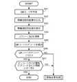
図5は、プロジェクター1がQRコードを投写する処理を示すフローチャートである。以下の処理は、プロジェクター1に対して、QRコードを投写させるための指示(以下、「QRコード投写指示」という)が入力されたことを契機として開始される。QRコード投写指示は、例えば、ユーザーがコントローラーRまたは操作パネル109を操作することにより入力される。2. Operation FIG. 5 is a flowchart showing a process in which the
ステップSA1において、MCU100は、無線接続用の暗号化キーとSSIDとをエンコードすることによりQRコードを生成する。暗号化キーとSSIDとは、予め記憶部103に記憶されている。なお、QRコードには、欠損によりQRコードの一部が読み取れない場合であっても、読み取り側の装置がエンコードされた情報を復元できるようにするための情報(以下、「誤り訂正情報」という)が含まれる。以下では、エンコードされた情報を誤り訂正情報により復元することが可能な欠損の割合の上限を、QRコードの「誤り訂正レベル」と表現する。MCU100は、記憶部103から暗号化キーとSSIDとを読み出して、誤り訂正レベルが所定のレベルのQRコードを生成する。QRコードは、コード中のセルの数がバージョン毎に異なる。MCU100は、所定のバージョンのQRコードを生成する。MCU100は、生成されたQRコードをRAM102に記憶する。ステップSA2において、MCU100は、無線接続用画像を生成する。具体的には、MCU100は、生成されたQRコードと、所定の画像(例えば、白一色の画像)とを合成して無線接続用画像を生成する。所定の画像は、予め記憶部103に記憶されている。ステップSA3において、MCU100は、無線接続用画像をスクリーンSCに投写する。 In step SA1, the
図6は、スクリーンSCに投写された無線接続用画像を示す図である。図6の例では、QRコードd2は、無線接続用画像W1の中央に配置されている。 FIG. 6 is a diagram showing an image for wireless connection projected on the screen SC. In the example of FIG. 6, the QR code d2 is arranged in the center of the wireless connection image W1.
再び図5を参照する。ステップSA4において、MCU100は、無線接続用画像が投写されたスクリーンSCを撮像する。MCU100は、撮像画像を示す画像データをRAM102に記憶する。ステップSA5において、MCU100は、撮像画像からQRコードを抜き出して、当該QRコードのデコードを開始する。ステップSA6において、MCU100は、QRコードがデコードできたか否かを判断する。具体的には、デコードが開始されてから所定の時間内にデコードされた情報が得られた場合には、MCU100は、QRコードがデコードできたと判断する。所定の時間内にデコードされた情報が得られない場合、またはデコード中にエラーが発生した場合には、MCU100は、QRコードがデコードできていないと判断する。QRコードがデコードできたと判断された場合(SA6:YES)、MCU100は、デコードされた情報をRAM102に記憶し、処理をステップSA7に移行する。QRコードがデコードできていないと判断された場合(SA6:NO)、MCU100は、投写される無線接続用画像を変更するための処理(以下、「画像変更処理」という)を行う。画像変更処理については後述する。 Refer to FIG. 5 again. In step SA4, the
ステップSA7において、MCU100は、エンコードされた情報とデコードされた情報とが一致しているか否かを判断する。具体的には、MCU100は、デコードされた情報が、記憶部103に記憶された暗号化キーとSSIDに一致しているか否かを判断する。エンコードされた情報とデコードされた情報とが一致していると判断された場合(SA7:YES)、MCU100は、処理を終了する。エンコードされた情報とデコードされた情報とが一致していないと判断された場合(SA7:NO)、MCU100は、画像変更処理を行う。 In step SA7, the
図7は、プロジェクター1による画像変更処理を示すフローチャートである。ステップSB1において、MCU100は、無線接続用画像内に占めるQRコードの位置(以下、「投写位置」という)を変更する。具体的には、ROM101には投写位置について複数のパターン(以下、「位置パターン」という)が記憶されており、当該位置パターンには予め優先度が与えられている。MCU100は、優先度に従って複数の位置パターンの中から一の位置パターンを選択し、当該位置パターンに応じて投写位置を順次変更する。なお、この例で、位置パターンは、QRコードが表示される位置の情報を表す。複数の位置パターンは、互いに異なる位置の情報を表す。 FIG. 7 is a flowchart showing image change processing by the
ステップSB2において、MCU100は、QRコードがデコードできたか否かを判断する。具体的には、MCU100は、無線接続用画像が投写されたスクリーンSCを再び撮像し、撮像画像からQRコードを抜き出して、当該QRコードのデコードを開始する。MCU100は、ステップSA6と同様の処理によりQRコードがデコードできたか否かを判断する。QRコードがデコードできたと判断された場合(SB2:YES)、MCU100は、処理をステップSB3に移行する。QRコードがデコードできていないと判断された場合(SB2:NO)、MCU100は、処理をステップSB4に移行する。 In step SB2, the
ステップSB3において、MCU100は、ステップSA7と同様の処理により、エンコードされた情報とデコードされた情報とが一致しているか否かを判断する。エンコードされた情報とデコードされた情報とが一致していると判断された場合(SB3:YES)、MCU100は、処理を終了する。エンコードされた情報とデコードされた情報とが一致していないと判断された場合(SB3:NO)、MCU100は、処理をステップSB4に移行する。 In step SB3, the
ステップSB4において、MCU100は、ROM101に記憶されたすべての位置パターンが選択されたか否かを判断する。MCU100は、ステップSB1において、選択した位置パターンを他の位置パターンと区別するための情報をRAM102に記憶している。MCU100は、当該情報がすべての位置パターンについて記憶されているか否かにより、すべての位置パターンが選択されたか否かを判断する。すべての位置パターンが選択されたと判断された場合(SB4:YES)、MCU100は、処理をステップSB5に移行する。選択されていない位置パターンがあると判断された場合(SB4:NO)、MCU100は、処理をステップSB1に移行し、次の優先度の位置パターンに応じて投写位置を変更する。このように、エンコードされた情報とデコードされた情報とが一致していないと判断された場合には、投写位置が繰り返し変更される。 In step SB4, the
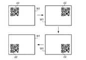
図8は、ステップSB1からSB4の処理により投写位置が変更された場合の無線接続用画像の遷移を示す図である。図8は、ROM101に4通りの位置パターンが記憶されている場合の遷移を示す。この例で、QRコードd2は、4通りの位置パターンに応じて、無線接続用画像W1の左上、右上、右下、左下の順に投写位置が変更されている。ステップSB1からSB4の処理により、ユーザーが投写位置を変更するための操作を行わなくても、読み取りに適した投写位置にQRコードが投写される。例えば、プロジェクター1とスクリーンSCとの間に障害物があることによりプロジェクター1から投写される光が遮られ、QRコードの一部が欠けて投写された場合に、欠けることのない位置にQRコードが投写される。別の例で、スクリーンSCの汚れによりQRコードの一部が映し出されない場合に、汚れのない位置にQRコードが投写される。 FIG. 8 is a diagram illustrating the transition of the wireless connection image when the projection position is changed by the processing from step SB1 to SB4. FIG. 8 shows transitions when four kinds of position patterns are stored in the
再び図7を参照する。ステップSB5において、MCU100は、無線接続用画像内に占めるQRコードの大きさを変更する。具体的には、ROM101にはQRコードの大きさについて複数のパターン(以下、「大きさパターン」という)が記憶されており、当該大きさパターンには予め優先度が与えられている。MCU100は、優先度に従って複数の大きさパターンの中から一の大きさパターンを選択し、当該大きさパターンに応じてQRコードの大きさを順次変更する。なお、この例で、大きさパターンは、無線接続用画像内に占めるQRコードの大きさの情報を表す。複数の大きさパターンは、互いに異なる大きさの情報を表す。 Refer to FIG. 7 again. In step SB5, the
ステップSB6およびSB7において、MCU100は、ステップSB2およびSB3と同様の処理を行う。ステップSB8において、MCU100は、ROM101に記憶されたすべての大きさパターンが選択されたか否かを判断する。MCU100は、ステップSB4と同様の処理によりすべての大きさパターンが選択されたか否かを判断する。すべての大きさパターンが選択されたと判断された場合(SB8:YES)、MCU100は、処理をステップSB9に移行する。選択されていない大きさパターンがあると判断された場合(SB8:NO)、MCU100は、処理をステップSB5に移行し、次の優先度の大きさパターンに応じてQRコードの大きさを変更する。このように、エンコードされた情報とデコードされた情報とが一致していないと判断された場合には、QRコードの大きさが繰り返し変更される。 In steps SB6 and SB7, the
図9は、ステップSB5からSB8の処理によりQRコードの大きさが変更された場合の無線接続用画像の遷移を示す図である。図9は、ROM101に4通りの大きさパターンが記憶されている場合の遷移を示す。この例で、QRコードd2は、4通りの大きさパターンに応じて、大きさが次第に大きくなるように変更されている。ステップSB5からSB8の処理により、ユーザーがQRコードの大きさを変更するための操作を行わなくても、読み取りに適した大きさのQRコードが投写される。例えば、スクリーンSCに投写されたQRコードの大きさが小さいことが原因でQRコードがデコードできない場合に、より大きなQRコードが投写される。 FIG. 9 is a diagram illustrating the transition of the wireless connection image when the size of the QR code is changed by the processing from step SB5 to SB8. FIG. 9 shows a transition when four kinds of size patterns are stored in the
再び図7を参照する。ステップSB9において、MCU100は、QRコードの誤り訂正レベルを変更する。具体的には、MCU100は、所定の規則に従って誤り訂正レベルを順次変更し、変更後の誤り訂正レベルでQRコードを再び生成する。ステップSB10およびSB11において、MCU100は、ステップSB2およびSB3と同様の処理を行う。ステップSB12において、MCU100は、すべての誤り訂正レベルのQRコードが投写されたか否かを判断する。すべての誤り訂正レベルのQRコードが投写されたと判断された場合(SB12:YES)、MCU100は、処理をステップSB13に移行する。投写されていない誤り訂正レベルのQRコードがあると判断された場合(SB12:NO)、MCU100は、処理をステップSB9に移行し、次の誤り訂正レベルでQRコードを生成する。このように、エンコードされた情報とデコードされた情報とが一致していないと判断された場合には、誤り訂正レベルが繰り返し変更される。 Refer to FIG. 7 again. In step SB9, the
図10は、ステップSB9からSB12の処理により誤り訂正レベルが変更された場合の無線接続用画像の遷移を示す図である。図10は、QRコードの誤り訂正レベルが7%、15%、25%、および30%に変更された場合の遷移を示す。この例で、QRコードd2は、誤り訂正レベルが次第に高くなるように変更されている。ステップSB9からSB12の処理により、ユーザーがQRコードの誤り訂正レベルを変更するための操作を行わなくても、読み取りに適した誤り訂正レベルのQRコードが投写される。また、無線接続用画像内に占めるQRコードの位置関係(位置および大きさなど)を変更してもデコードが失敗する場合に、読み取りに適したQRコードが投写される。なお、誤り訂正レベルの変更は、QRコードの位置関係を変更するのに比べてプロジェクター1への処理負荷が高いため、QRコードの位置関係を変更してもデコードが失敗する場合に行われることが望ましい。 FIG. 10 is a diagram illustrating a transition of the wireless connection image when the error correction level is changed by the processing from step SB9 to SB12. FIG. 10 shows the transition when the error correction level of the QR code is changed to 7%, 15%, 25%, and 30%. In this example, the QR code d2 is changed so that the error correction level gradually increases. Through the processing of steps SB9 to SB12, a QR code having an error correction level suitable for reading is projected even if the user does not perform an operation for changing the error correction level of the QR code. In addition, when decoding fails even if the positional relationship (position and size, etc.) of the QR code occupying the wireless connection image is changed, a QR code suitable for reading is projected. The error correction level is changed when the processing load on the
再び図7を参照する。ステップSB13において、MCU100は、QRコードのデコードが失敗したことを示すメッセージ(以下、「エラーメッセージ」という)をスクリーンSCに投写する。エラーメッセージは、例えば、ROM101に記憶されている。エラーメッセージには、例えば、「投写面を変えてください」などのメッセージが含まれる。 Refer to FIG. 7 again. In step SB13, the
<変形例>
本発明は、上述の実施形態に限定されるものではなく、種々の変形実施が可能である。以下、変形例をいくつか説明する。以下で説明する変形例のうち、2つ以上のものが組み合わされて用いられてもよい。<Modification>
The present invention is not limited to the above-described embodiments, and various modifications can be made. Hereinafter, some modifications will be described. Two or more of the modifications described below may be used in combination.
(1)変形例1
プロジェクター1が読み取りに適したQRコードを投写する処理は、図7に示した処理に限らない。プロジェクター1は、無線接続用画像を投写する条件を変更することにより、読み取りに適したQRコードを投写してもよい。例えば、プロジェクター1は、無線接続用画像が投写されたスクリーンSCを撮像し、撮像画像の階調値のヒストグラムを解析することにより、無線接続用画像のコントラストまたは明るさを変更してもよい。別の例で、プロジェクター1は、撮像画像に応じて無線接続用画像の色調(例えば、ダイナミックモード、シネマモード、リビングモード、ナチュラルモードなどの各種カラーモード)を変更してもよい。また、プロジェクター1は、QRコードを所定の角度ずつ回転させることにより、読み取りに適したQRコードを投写してもよい。(1)
The process in which the
(2)変形例2
プロジェクター1により生成されるQRコードのバージョンは、必ずしも一定のバージョンでなくてもよい。プロジェクター1は、SSIDおよび暗号化キーの長さに応じて異なるバージョンのQRコードを生成してもよい。例えば、プロジェクター1は、SSIDおよび暗号化キーをエンコードする上で最小限のバージョンのQRコードを生成してもよい。これにより、タブレット端末2がQRコードを読み取るときの精度が向上する。また、QRコードが、SSIDおよび暗号化キー以外の情報(例えば、画像データまたはURLなど)を示す場合にも、当該情報の量に応じて異なるバージョンのQRコードが生成されてもよい。(2)
The version of the QR code generated by the
(3)変形例3
ステップSB13における処理は、エラーメッセージの投写に限らない。上述の通り、QRコードの投写位置、大きさ、および誤り訂正レベル(以下、「投写位置等」という)が変更された場合であっても、依然としてQRコードのデコードが失敗する可能性がある。このような場合、プロジェクター1は、無線接続用画像を示す画像データをプリンター3に出力し、プリンター3が用紙に無線接続用画像を形成してもよい。これにより、QRコードの投写位置等を変更してもQRコードのデコードが失敗する場合に、プロジェクター1とタブレット端末2との無線接続がより確実に行われる。別の例で、ステップSB13において、プロジェクター1は、エンコードされていない暗号化キーおよびSSIDをスクリーンSCに投写してもよい。(3)
The process in step SB13 is not limited to the projection of an error message. As described above, even when the QR code projection position, size, and error correction level (hereinafter referred to as “projection position, etc.”) are changed, decoding of the QR code may still fail. In such a case, the
(4)変形例4
コード画像が示す情報は、SSIDおよび暗号化キーに限らない。コード画像は、例えば、読み取り側の電子機器が接続しようとする無線LANの周波数帯域を示してもよい。また、コード画像が示す情報は、外部装置がプロジェクター1に無線接続するための情報に限らない。コード画像は、例えば、タブレット端末2が所定のアプリケーションソフトウェアをインストールするためにアクセスするURLを示してもよい。別の例で、コード画像は、プロジェクター1に対して設定されたパラメータ(例えば、明るさやコントラストなど)を示してもよい。(4) Modification 4
The information indicated by the code image is not limited to the SSID and the encryption key. For example, the code image may indicate a frequency band of a wireless LAN to which a reading-side electronic device is to be connected. Further, the information indicated by the code image is not limited to information for the external apparatus to wirelessly connect to the
(5)変形例5
プロジェクター1がQRコードを変更する処理は、誤り訂正レベルを変更する処理に限らない。プロジェクター1は、例えば、先にエンコードされたSSIDおよび暗号化キーと異なるSSIDおよび暗号化キーをエンコードすることにより、QRコードを変更してもよい。(5) Modification 5
The process of changing the QR code by the
(6)変形例6
位置パターン、大きさパターン、および誤り訂正レベルは、実施形態に示した4通りのパターンおよびレベルに限らない。また、プロジェクター1は、位置パターンおよび大きさパターンを記憶していなくてもよい。この場合、MCU100は、所定のプログラムを実行することにより、QRコードの位置および大きさを変更してもよい。また、プロジェクター1が、QRコードの投写位置、大きさ、および誤り訂正レベルを変更する順番は、実施形態に示した順番に限らない。例えば、プロジェクター1は、QRコードの大きさを変更した後に投写位置を変更してもよい。さらに、プロジェクター1は、QRコードの投写位置、大きさ、および誤り訂正レベルのうち、2つ以上の条件を同時に変更してもよい。例えば、プロジェクター1は、QRコードの投写位置および大きさを同時に変更してもよい。(6) Modification 6
The position pattern, the size pattern, and the error correction level are not limited to the four patterns and levels shown in the embodiment. Further, the
(7)変形例7
QRコードの投写位置等を変更する処理は、ユーザーがコントローラーRまたは操作パネル109を操作することにより行われてもよい。この場合、プロジェクター1は、ユーザーの操作により投写位置等の変更を受け付けるマニュアルモードと、図5および図7の処理により投写位置等が変更されるオートモードとを備えており、ユーザーはQRコード投写指示を入力した後にいずれかのモードを選択してもよい。(7) Modification 7
The process of changing the QR code projection position or the like may be performed by the user operating the controller R or the
(8)変形例8
コード画像は、QRコードに限らない。コード画像は、エンコードされた情報を示す画像であれば、例えば、PDF417、CP(Communication Platform)コード、HCCB(High Capacity Color Barcode)などの他の二次元コードであってもよい。また、コード画像は、一次元コードであってもよい。(8) Modification 8
The code image is not limited to a QR code. The code image may be another two-dimensional code such as PDF417, CP (Communication Platform) code, or HCCB (High Capacity Color Barcode) as long as it is an image indicating encoded information. The code image may be a one-dimensional code.
(9)変形例9
プロジェクター1は、QRコードの投写位置と光学系136の焦点とが重なるように光学系136を制御してもよい。例えば、図8に示した順番でQRコードの投写位置が変更される場合、プロジェクター1は、投写位置が変更されるタイミングに合わせて光学系136の焦点を左上、右上、右下、左下に変更してもよい。(9) Modification 9
The
(10)変形例10
ステップSA7の処理は省略されてもよい。この場合、ステップSA6において、QRコードがデコードできたと判断された場合、MCU100は、処理を終了する。また、ステップSB3、SB7、およびSB11の処理は省略されてもよい。この場合、ステップSB2、SB6、およびSB10において、QRコードがデコードできたと判断された場合、MCU100は、処理を終了する。(10) Modification 10
The process of step SA7 may be omitted. In this case, if it is determined in step SA6 that the QR code has been decoded, the
(11)変形例11
投写システムPSにおいて、プロジェクター1と無線接続される外部装置は、タブレット端末2に限らない。タブレット端末2に替えて、QRコードの読み取り機能を備えた携帯電話機またはパーソナルコンピューターなどが用いられてもよい。(11)
In the projection system PS, the external device wirelessly connected to the
(12)変形例12
プロジェクター1は、優先度に従ってQRコードの投写位置および大きさを変更しなくてもよい。プロジェクター1は、投写される光が障害物により遮られない位置を検出し、当該位置にQRコードが投写されるようにQRコードの投写位置および大きさを変更してもよい。この場合、プロジェクター1は、例えば、スクリーンSCを撮像し、撮像画像と液晶パネル126に書き込まれた画像とを比較することにより、投写される光が障害物により遮られない位置を検出する。(12)
The
(13)変形例13
プロジェクター1は、エンコードされた情報とデコードされた情報とが一致していると判断されるまで、投写位置等を変更する処理を繰り返してもよい。この場合、ステップSB13の処理は省略され、ステップSB12において、すべての誤り訂正レベルのQRコードが投写されたと判断された場合、MCU100は、処理をステップSB1に移行する。(13)
The
(14)変形例14
プロジェクター1およびタブレット端末2のハードウェア構成は、図3および図4に示した構成に限らない。図5および図7に示した処理が実行されれば、各装置はどのようなハードウェア構成を有していてもよい。例えば、液晶パネル126は、反射型の液晶パネルであってもよい。また、液晶パネル126に代えて、有機EL(ElectroLuminescence)素子、デジタルミラーデバイス(DMD)等の電気光学素子が用いられてもよい。また、液晶パネル126は色成分毎に設けられていなくてもよく、プロジェクター1は単一の液晶パネル126を有していてもよい。この場合、各色成分の画像は時分割で表示されてもよい。(14)
The hardware configurations of the
1…プロジェクター、11…画像生成手段、12…投写手段、13…撮像手段、14…デコード手段、15…変更手段、16…投写制御手段、100…MCU、101…ROM、102…RAM、103…記憶部、104…IF部、105…画像処理回路、106…投写ユニット、116…光源、126…液晶パネル、136…光学系、146…光源駆動回路、156…パネル駆動回路、166…光学系駆動回路、107…イメージセンサー、108…受光部、109…操作パネル、110…入力処理部、2…タブレット端末、200…CPU、201…ROM、202…RAM、203…IF部、204…タッチパネル、205…撮像部、206…記憶部、3…プリンター DESCRIPTION OF
Claims (8)
Translated fromJapanese前記第1の投写画像を投写する投写手段と、
前記第1の投写画像が投写された投写面を撮像する撮像手段と、
前記撮像手段により撮像された撮像画像から前記コード画像を抜き出してデコードするデコード手段と、
前記デコード手段によるデコードが失敗した場合に、前記画像生成手段が画像を生成する条件を変更する変更手段と、
前記画像生成手段を制御して前記変更手段により変更された前記条件に応じた第2の投写画像を生成させるとともに、前記投写手段を制御して前記第1の投写画像の代わりに前記第2の投写画像を投写させる投写制御手段と
を有する投写装置。Image generating means for generating a code image indicating encoded information and generating a first projection image including the code image;
Projection means for projecting the first projection image;
Imaging means for imaging a projection surface on which the first projection image is projected;
Decoding means for extracting and decoding the code image from a captured image captured by the imaging means;
A changing means for changing a condition for the image generating means to generate an image when decoding by the decoding means fails;
The image generation means is controlled to generate a second projection image corresponding to the condition changed by the change means, and the projection means is controlled to change the second projection image instead of the first projection image. A projection apparatus comprising: projection control means for projecting a projected image.
ことを特徴とする請求項1に記載の投写装置。The projection apparatus according to claim 1, wherein the changing unit changes a code image generated by the image generating unit.
前記変更手段は、前記誤りを訂正するための情報を変更する
ことを特徴とする請求項2に記載の投写装置。The code image includes information for correcting an error,
The projection apparatus according to claim 2, wherein the changing unit changes information for correcting the error.
ことを特徴とする請求項1ないし3のいずれか1項に記載の投写装置。The projection apparatus according to any one of claims 1 to 3, wherein the changing unit changes a positional relationship of the code image in the projection image.
ことを特徴とする請求項1ないし4のいずれか1項に記載の投写装置。5. The projection according to claim 1, wherein the projection control unit changes a condition under which the projection unit projects the projection image when the decoding by the decoding unit fails. apparatus.
ことを特徴とする請求項1ないし5のいずれか1項に記載の投写装置。6. The projection apparatus according to claim 1, wherein when the decoding by the decoding unit fails, the changing unit sequentially changes the condition according to a predetermined priority. 7.
ことを特徴とする請求項1ないし6のいずれか1項に記載の投写装置。The projection apparatus according to any one of claims 1 to 6, wherein the code image shows information for an external apparatus to wirelessly connect to the own apparatus.
前記第1の投写画像を投写するステップと、
前記第1の投写画像が投写された投写面を撮像するステップと、
撮像された撮像画像から前記コード画像を抜き出してデコードするステップと、
前記デコードが失敗した場合に、前記コード画像または前記第1の投写画像の少なくとも一方が生成される条件を変更するステップと、
変更された条件に応じた第2の投写画像を生成するとともに、前記第1の投写画像の代わりに前記第2の投写画像を投写するステップと
を有する投写方法。Generating a code image indicating the encoded information and generating a first projection image including the code image;
Projecting the first projected image;
Imaging a projection plane on which the first projection image is projected;
Extracting and decoding the code image from the captured image, and
Changing a condition under which at least one of the code image or the first projection image is generated when the decoding fails;
And a step of generating a second projection image corresponding to the changed condition and projecting the second projection image instead of the first projection image.
Priority Applications (1)
| Application Number | Priority Date | Filing Date | Title |
|---|---|---|---|
| JP2014021739AJP2015148964A (en) | 2014-02-06 | 2014-02-06 | Projection device and projection method |
Applications Claiming Priority (1)
| Application Number | Priority Date | Filing Date | Title |
|---|---|---|---|
| JP2014021739AJP2015148964A (en) | 2014-02-06 | 2014-02-06 | Projection device and projection method |
Publications (1)
| Publication Number | Publication Date |
|---|---|
| JP2015148964Atrue JP2015148964A (en) | 2015-08-20 |
Family
ID=53892271
Family Applications (1)
| Application Number | Title | Priority Date | Filing Date |
|---|---|---|---|
| JP2014021739APendingJP2015148964A (en) | 2014-02-06 | 2014-02-06 | Projection device and projection method |
Country Status (1)
| Country | Link |
|---|---|
| JP (1) | JP2015148964A (en) |
Cited By (6)
| Publication number | Priority date | Publication date | Assignee | Title |
|---|---|---|---|---|
| JP2017049970A (en)* | 2015-09-01 | 2017-03-09 | 株式会社デンソーウェーブ | Information code reading system |
| JP2017093820A (en)* | 2015-11-25 | 2017-06-01 | 株式会社スクウェア・エニックス | Display system and control program |
| JP2018093258A (en)* | 2016-11-30 | 2018-06-14 | キヤノン株式会社 | Display system, control device and method for projection display device |
| JP2019125288A (en)* | 2018-01-19 | 2019-07-25 | セイコーエプソン株式会社 | Code conversion device, method of producing output product, and code conversion program |
| US11303708B2 (en) | 2018-08-08 | 2022-04-12 | Seiko Epson Corporation | Communication system, communication method, display device, and communication terminal |
| JP2025029181A (en)* | 2016-05-20 | 2025-03-05 | キヤノン株式会社 | Information processing device, control method thereof, and program |
- 2014
- 2014-02-06JPJP2014021739Apatent/JP2015148964A/enactivePending
Cited By (8)
| Publication number | Priority date | Publication date | Assignee | Title |
|---|---|---|---|---|
| JP2017049970A (en)* | 2015-09-01 | 2017-03-09 | 株式会社デンソーウェーブ | Information code reading system |
| JP2017093820A (en)* | 2015-11-25 | 2017-06-01 | 株式会社スクウェア・エニックス | Display system and control program |
| JP2025029181A (en)* | 2016-05-20 | 2025-03-05 | キヤノン株式会社 | Information processing device, control method thereof, and program |
| JP7679537B2 (en) | 2016-05-20 | 2025-05-19 | キヤノン株式会社 | Information processing device, control method thereof, and program |
| JP2018093258A (en)* | 2016-11-30 | 2018-06-14 | キヤノン株式会社 | Display system, control device and method for projection display device |
| JP2019125288A (en)* | 2018-01-19 | 2019-07-25 | セイコーエプソン株式会社 | Code conversion device, method of producing output product, and code conversion program |
| JP7010016B2 (en) | 2018-01-19 | 2022-01-26 | セイコーエプソン株式会社 | Code converter, output production method and code converter |
| US11303708B2 (en) | 2018-08-08 | 2022-04-12 | Seiko Epson Corporation | Communication system, communication method, display device, and communication terminal |
Similar Documents
| Publication | Publication Date | Title |
|---|---|---|
| US9135490B1 (en) | Communication system, image pickup device, program, and communication method | |
| JP2015148964A (en) | Projection device and projection method | |
| US11611731B2 (en) | Evaluation method for image projection system, image projection system, and image projection control apparatus | |
| JP2017083550A (en) | Information processing apparatus, image projection system, and program | |
| JP2016014713A (en) | Image projection apparatus, image projection method, and control program for image projection apparatus | |
| US20150161767A1 (en) | Image transmitting apparatus, image presentation system and control method | |
| JP7154877B2 (en) | Image projection device, image projection device control method, and program | |
| US11277594B2 (en) | Control method for image projection system and image projection system | |
| CN110740303A (en) | Display device and control method of display device | |
| JP5200364B2 (en) | Projector, control method therefor, and program | |
| US20150138512A1 (en) | Information processing apparatus, image projecting apparatus, and method for providing distortion correction instruction | |
| US11832031B2 (en) | Projection system controlling method, and projector | |
| CN101441393A (en) | Projection device for image projection with document camera device connected thereto, and projection method | |
| US10349026B2 (en) | Projector, method for controlling the same, and projection system | |
| US10839482B2 (en) | Information processing apparatus, image display method, display system, and computer readable storage medium | |
| JP2015179935A (en) | Communication system, communication method, and display device | |
| JP2015177285A (en) | communication system and communication method | |
| US11778150B2 (en) | Image supply device, display system, and method for direct display of second image | |
| US11350067B2 (en) | Evaluation method for image projection system, image projection system, and image projection control apparatus | |
| JP4946736B2 (en) | Document camera apparatus, image processing apparatus, image processing method, and program | |
| JP2018004801A (en) | Image display device | |
| JP6464834B2 (en) | Display device and display method | |
| JP6427888B2 (en) | Image display system, image display apparatus, and image display method | |
| JP2017200021A (en) | Information processing apparatus, program, and system | |
| JP7226461B2 (en) | POSITION DETECTION METHOD, DISPLAY DEVICE AND POSITION DETECTION SYSTEM |