JP2015141312A - Display device and line-of-sight estimation device - Google Patents
Display device and line-of-sight estimation deviceDownload PDFInfo
- Publication number
- JP2015141312A JP2015141312AJP2014014053AJP2014014053AJP2015141312AJP 2015141312 AJP2015141312 AJP 2015141312AJP 2014014053 AJP2014014053 AJP 2014014053AJP 2014014053 AJP2014014053 AJP 2014014053AJP 2015141312 AJP2015141312 AJP 2015141312A
- Authority
- JP
- Japan
- Prior art keywords
- image
- viewer
- line
- sight
- unit
- Prior art date
- Legal status (The legal status is an assumption and is not a legal conclusion. Google has not performed a legal analysis and makes no representation as to the accuracy of the status listed.)
- Granted
Links
Images


Classifications
- G—PHYSICS
- G06—COMPUTING OR CALCULATING; COUNTING
- G06F—ELECTRIC DIGITAL DATA PROCESSING
- G06F3/00—Input arrangements for transferring data to be processed into a form capable of being handled by the computer; Output arrangements for transferring data from processing unit to output unit, e.g. interface arrangements
- G06F3/01—Input arrangements or combined input and output arrangements for interaction between user and computer
- G06F3/011—Arrangements for interaction with the human body, e.g. for user immersion in virtual reality
- G06F3/013—Eye tracking input arrangements
- G—PHYSICS
- G06—COMPUTING OR CALCULATING; COUNTING
- G06F—ELECTRIC DIGITAL DATA PROCESSING
- G06F3/00—Input arrangements for transferring data to be processed into a form capable of being handled by the computer; Output arrangements for transferring data from processing unit to output unit, e.g. interface arrangements
- G06F3/002—Specific input/output arrangements not covered by G06F3/01 - G06F3/16
- G06F3/005—Input arrangements through a video camera
Landscapes
- Engineering & Computer Science (AREA)
- Theoretical Computer Science (AREA)
- General Engineering & Computer Science (AREA)
- Human Computer Interaction (AREA)
- Physics & Mathematics (AREA)
- General Physics & Mathematics (AREA)
- Multimedia (AREA)
- Controls And Circuits For Display Device (AREA)
- User Interface Of Digital Computer (AREA)
Abstract
Translated fromJapaneseDescription
Translated fromJapanese本発明の実施形態は、表示装置及び視線推定装置に関する。 Embodiments described herein relate generally to a display device and a line-of-sight estimation device.
例えば、使用者が頭部に装着するヘッドマウントディスプレイ(HMD)が提案されている。例えば、外界重畳型のヘッドマウントディスプレイにおいて、使用者が遠方を見ているか近方を見ているかに依らず、ディスプレイの表示画面を見やすくすることが望まれる。このような使い易い表示装置及び視線推定装置が望まれる。 For example, a head mounted display (HMD) that a user wears on the head has been proposed. For example, in an externally superimposed head mounted display, it is desired to make the display screen easy to see regardless of whether the user is looking far or near. Such an easy-to-use display device and line-of-sight estimation device are desired.
本発明の実施形態は、使い易い表示装置及び視線推定装置を提供する。 Embodiments of the present invention provide an easy-to-use display device and line-of-sight estimation device.
本発明の実施形態によれば、撮像部と、画像表示部と、を含む表示装置が提供される。前記撮像部は、観視者の瞼の第1状態における第1画像を撮像する。前記画像表示部は、光出射部と、光学部と、を含む。前記光出射部は、画像情報を含む光を出射する。前記光学部は前記光が入射し、前記光の少なくとも一部の光を前記観視者の眼球へ入射させるコンバイナを含む。前記画像表示部は、前記撮像部で撮像された前記第1画像に基づいて、前記少なくとも一部の前記光の前記眼球に対する入射方向を変更する。 According to the embodiment of the present invention, a display device including an imaging unit and an image display unit is provided. The imaging unit captures a first image in a first state of the viewer's eyelid. The image display unit includes a light emitting unit and an optical unit. The light emitting unit emits light including image information. The optical unit includes a combiner that allows the light to enter and causes at least part of the light to enter the eyeball of the viewer. The image display unit changes an incident direction of the at least part of the light with respect to the eyeball based on the first image captured by the imaging unit.
以下に、各実施の形態について図面を参照しつつ説明する。
なお、図面は模式的または概念的なものであり、各部分の厚みと幅との関係、部分間の大きさの比率などは、必ずしも現実のものと同一とは限らない。また、同じ部分を表す場合であっても、図面により互いの寸法や比率が異なって表される場合もある。
なお、本願明細書と各図において、既出の図に関して前述したものと同様の要素には同一の符号を付して詳細な説明は適宜省略する。Each embodiment will be described below with reference to the drawings.
The drawings are schematic or conceptual, and the relationship between the thickness and width of each part, the size ratio between the parts, and the like are not necessarily the same as actual ones. Further, even when the same part is represented, the dimensions and ratios may be represented differently depending on the drawings.
Note that, in the present specification and each drawing, the same elements as those described above with reference to the previous drawings are denoted by the same reference numerals, and detailed description thereof is omitted as appropriate.
図1は、実施形態に係る表示装置を例示する模式図である。
図1に表したように、実施形態に係る表示装置100は、画像表示部10と、撮像部20と、を含む。FIG. 1 is a schematic view illustrating the display device according to the embodiment.
As illustrated in FIG. 1, the
画像表示部10は、光学部15と、光出射部17と、を含む。光出射部17は、画像情報を含む光を出射する。画像情報を含む光の少なくとも一部は、光学部15へ入射する。光学部15は、入射した画像情報を含む光の少なくとも一部を観視者50の眼51へ向けて進行させる(入射させる)。これにより、観視者50は、画像を知覚する。表示装置100は、例えば、使用者(観視者)の頭部に装着されるヘッドマウントディスプレイ(HMD)である。 The
この例では、表示装置100は、保持部40をさらに含む。保持部40は、例えば、画像表示部10及び撮像部20を保持する。保持部40は、例えば、画像表示部10と観視者50の眼51との間の空間的配置を規定する。保持部40は、例えば、画像表示部10と、撮像部20との空間的配置を規定する。保持部40の形状は、例えば、眼鏡のフレームのような形状である。 In this example, the
光出射部17(表示パネル)には、例えば、透過型の液晶ディスプレイ(LCD:Liquid Crystal Display)パネルが用いられる。光出射部17には、有機ELパネル、LCOS(Liquid Crystal On Silicon)パネルまたはDMD(Digital Micromirror Device)パネルなどを用いても良い。光出射部17には、レーザ光源を用いても良い。この場合にはレーザ光源をラスタスキャンすることによって画像を表示する。 For the light emitting unit 17 (display panel), for example, a transmissive liquid crystal display (LCD) panel is used. An organic EL panel, an LCOS (Liquid Crystal On Silicon) panel, a DMD (Digital Micromirror Device) panel, or the like may be used for the
この例では、表示装置100は、駆動回路30をさらに含む。駆動回路30は、光出射部17と電気的に接続され、光出射部17の動作を制御する。駆動回路30は、画像表示部10と一体として設けられても良い。 In this example, the
光学部15は、例えば、接眼レンズ13と、コンバイナ12と、を含む。光出射部17を出射した画像情報を含む光の光路上において、光出射部17と眼51との間に接眼レンズ13が設けられる。画像情報を含む光の光路上において、接眼レンズ13と眼51との間にコンバイナ12が設けられる。 The
この例において、例えば、眼51からコンバイナ12へ向かう方向をY軸方向とする。Y軸方向と垂直な1つの方向をX軸方向とする。X軸方向に対して垂直でY軸方向に対して垂直な方向をZ軸方向とする。例えば、X軸方向は、観視者50の右方向である。例えば、Y軸方向は、観視者50の正面方向である。例えば、Z軸方向は、観視者50の上方向である。 In this example, for example, the direction from the
例えば、画像情報を含む光の少なくとも一部は、接眼レンズ13によって集光され、コンバイナ12に入射する。コンバイナ12は、入射した光の少なくとも一部を眼51(眼球)へ入射させる。これにより、例えば、光出射部17によって表示される画像が虚像として観視者50に表示される。 For example, at least part of the light including image information is collected by the
コンバイナ12には、例えば、ハーフミラーが用いられる。画像情報を含む光は、ハーフミラーによって反射され、眼51へ向かって進行する。ハーフミラーを用いることで、例えば、観視者50は、外光と画像とを同時に見ることができる。 For the
コンバイナ12は、コンバイナ12の眼51とは反対側から眼51へ向かって進行する外光の少なくとも一部を透過させる。これにより、観視者50は、外光と画像とを同時に見ることができる。 The
ハーフミラーは、例えば、ガラス板または透明プラスチック板の上にアルミを蒸着させることによって、作られる。ハーフミラーには、ガラス板や透明プラスチック板の上に誘電体多層膜を設けたものを用いても良い。 The half mirror is made, for example, by depositing aluminum on a glass plate or a transparent plastic plate. As the half mirror, a glass plate or a transparent plastic plate provided with a dielectric multilayer film may be used.
コンバイナ12は、眼鏡レンズと一体であってもよい。すなわち、眼鏡(保持部40)のレンズ面を光反射性とし、ここに画像情報を含む光を入射させても良い。 The
撮像部20は、例えば、観視者50の眼51を撮像する。撮像部20は、観視者50の瞼の第1状態における第1画像を撮像する。撮像部20には、例えば、カメラが用いられる。撮像部20は、例えば、保持部40に取り付けられ、観視者50の眼51の全体を撮像することができるように配置される。この例では、撮像部20は、観視者50の側面に配置されている。後述するように、撮像部20は、観視者50の正面に配置されても良い。 The
撮像部20によって撮像された瞼の像(第1画像)に基づいて、観視者50の視線の方向が検出(推定)される。検出された視線の方向に基づいて、画像表示部10は、眼51(眼球)へ入射する画像情報を含む光の少なくとも一部の、眼51(眼球)に対する入射方向を変更する。すなわち、画像表示部10は、眼51の位置に対する画像の表示位置を変更する。瞼の像に基づいて、観視者50の視線の方向が検出される。検出された視線の方向に基づいて、表示される画像が制御される。これにより、観視者50にとって見やすい位置に画像を表示することができる。 The direction of the line of sight of the
図2は、表示装置の動作を例示する模式図である。
図2は、表示装置100を用いた観視者50の視界を例示している。例えば、観視者50が遠方を見ているときには、観視者50の注視点は、点g1の付近である。このとき、例えば、表示装置100は、点g1の位置に合わせて、画像P1を表示している。FIG. 2 is a schematic view illustrating the operation of the display device.
FIG. 2 illustrates the field of view of the
例えば、人の視線は、遠方を見るときにはに上がり、近方を見るときには下がる。観視者50が近方を見ているときには、観視者50の注視点は、例えば、点g2の付近である。例えば、観視者50が正面の遠方を見ているときの観視者50の視線の方向と、観視者50が近方(例えば手元付近)を見ているときの観視者50の視線の方向と、の間の角度は、30度(°)〜40°程度である。 For example, a person's line of sight rises when looking far away and falls when looking near. When the
例えば、遠近両用眼鏡において、このような視線の変化が応用されている。遠近両用眼鏡のレンズにおいては、遠方を見るときの視線方向に対応する部分の光学特性(度数)と、近方を見るときの視線方向に対応する部分の光学特性(度数)とは、異なる。 For example, such a change in the line of sight is applied to bifocal glasses. In the lens of the bifocal glasses, the optical characteristic (frequency) of the part corresponding to the line-of-sight direction when looking at the distance is different from the optical characteristic (frequency) of the part corresponding to the line-of-sight direction when looking at the near side.
例えば、参考例のヘッドマウントディスプレイにおいて、画像が表示される範囲を広く設定される場合がある。例えば、表表示範囲の上端へ向かう視線の方向と、表示範囲の下端へ向かう視線の方向と、の間の角度(垂直方向における画角)を、30°〜40°程度とする。これにより、遠方を見るときの視線の方向と近方を見るときの視線の方向との両方に対応することができる。 For example, in the head mounted display of the reference example, the range in which an image is displayed may be set wide. For example, the angle (view angle in the vertical direction) between the direction of the line of sight toward the upper end of the front display range and the direction of the line of sight toward the lower end of the display range is set to about 30 ° to 40 °. Thereby, it is possible to cope with both the direction of the line of sight when looking at the distance and the direction of the line of sight when looking at the near.
しかし、画角を大きくする場合には、光学部15のサイズが大きくなりやすい。例えば、画角と光学部15のサイズとの間には相関がある。ヘッドマウントディスプレイを軽量で小型とするために、画角を大きくすることができない場合がある。 However, when the angle of view is increased, the size of the
これに対して、実施形態に係る表示装置においては、観視者の視線が検出され、検出された視線に応じて表示される画像の位置が変更される。これにより、光学部15のサイズの増大を抑制し、遠方を見るときの視線方向と近方を見るときの視線方向との両方に対応することができる。 On the other hand, in the display device according to the embodiment, the line of sight of the viewer is detected, and the position of the displayed image is changed according to the detected line of sight. Thereby, an increase in the size of the
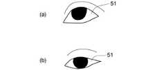
図3(a)及び図3(b)は、実施形態に係る表示装置の動作を例示する模式図である。 図3(a)及び図3(b)は、撮像部20で撮像された眼51の像を例示する模式図である。
図3(a)は、観視者50が正面(水平方向)の遠方を見ているときの眼51の像を例示している。図3(b)は、観視者50が近方(遠方を見ているときの視線の方向に対して、30°程度下側に向かう方向)を見ているときの眼51の像を例示している。FIG. 3A and FIG. 3B are schematic views illustrating the operation of the display device according to the embodiment. FIG. 3A and FIG. 3B are schematic views illustrating an image of the
FIG. 3A illustrates an image of the
図3(a)及び図3(b)に表したように、視線の方向によって眼の形状が異なる。遠方を見ているときの瞼の形状(眼の開き具合)と近方を見ているときの瞼の形状とは、異なる。表示装置100においては、例えば、この形状の違いを用いて、観視者50の視線方向を検出する。 As shown in FIGS. 3A and 3B, the shape of the eye varies depending on the direction of the line of sight. The shape of the eyelid when looking far away (the degree of eye opening) is different from the shape of the eyelid looking near. In the
図4は、実施形態に係る表示装置の動作を例示する模式図である。
図4は、表示装置100の動作のフローチャートを例示している。図4に表したように、表示装置100の動作は、例えば、キャリブレーション用画像撮像工程(ステップS1)と、画像保存工程(ステップS2)と、第1画像撮像工程(ステップS3)と、視線方向検出工程(ステップS4)と、視線方向判定工程(ステップS5)と、表示位置算出工程(ステップS6)と、光学系位置移動工程(ステップS7)と、を含む。FIG. 4 is a schematic view illustrating the operation of the display device according to the embodiment.
FIG. 4 illustrates a flowchart of the operation of the
例えば、ステップS1において、遠方を見ている状態(第2状態)の眼51の画像(第2画像)が、撮像部20によって撮像される。例えば、第2画像は、観視者50の視線が観視者50の正面を向いている状態の瞼の画像である。 For example, in step S <b> 1, an image (second image) of the
また、ステップS1において、近方を見ている状態(第3状態)の眼51の画像(第3画像)が、撮像部20によって撮像される。例えば、第3画像は、観視者50の視線が観視者50の下側を向いている状態の瞼の画像である。
例えば、ステップS2において、第2画像及び第3画像は、基準画像(キャリブレーション画像)として保持(保存)される。Further, in step S <b> 1, an image (third image) of the
For example, in step S2, the second image and the third image are held (saved) as reference images (calibration images).
第2状態における観視者50の視線の方向は、第3状態における観視者50の視線の方向と異なる。例えば、第3状態における観視者50の視線は下側を向いている。第2状態における観視者50の視線は、第3状態における観視者50の視線よりも上側を向いている。 The direction of the line of sight of the
例えば、ステップS1及びステップS2は、表示装置100の動作開始時に、毎回行われる。例えば、既に撮像されたデータ(画像)が保持されていれば、そのデータを呼び出してもよい。このように表示装置100の動作開始時に、ステップS1及びステップS2を毎回行わなくてもよい。
また、例えば、ユーザ(観視者50)と、撮像したキャリブレーション画像と、を対応づけて保持する。これにより、例えば、表示装置の使用時にユーザ認証を行い、キャリブレーション画像を呼び出すことができる。ユーザ認証には、IDによる認証、顔認証、または、虹彩認識など、任意の方法を用いることができる。キャリブレーション画像における人物と、第1画像における人物と、が同じ人物であることが好ましい。これにより視線方向の検出精度が向上する。キャリブレーション画像における人物と、第1画像における人物と、は、必ずしも同じ人物でなくてもよい。For example, step S1 and step S2 are performed every time the operation of the
Further, for example, the user (viewer 50) and the captured calibration image are held in association with each other. Thereby, for example, user authentication can be performed when the display device is used, and a calibration image can be called up. For user authentication, any method such as authentication by ID, face authentication, or iris recognition can be used. It is preferable that the person in the calibration image and the person in the first image are the same person. This improves the detection accuracy of the line-of-sight direction. The person in the calibration image and the person in the first image are not necessarily the same person.
例えば、ステップS3において、撮像部20は、観視者50の眼51(瞼)の画像(第1画像)を順次撮像する。 For example, in step S <b> 3, the
ステップS4において、観視者50の視線お方向が検出される。予め撮像された第2画像と、第1画像と、の比較、及び、予め撮像された第3画像と、第1画像と、の比較、によって視線の方向が検出される。 In step S4, the direction of the line of sight of the
例えば、順次撮像される第1画像のそれぞれにおいて、視線の方向が検出される。例えば、ステップS5において、検出された視線の方向の移動が判定される。例えば、検出された視線の方向に大きな変化がない場合は、表示装置100は、ステップS3〜S5を繰り返す。検出された視線の方向に大きな変化があった場合は、表示装置100は、例えば、ステップS6及びステップS7を行う。 For example, the direction of the line of sight is detected in each of the first images that are sequentially captured. For example, in step S5, the movement in the direction of the detected line of sight is determined. For example, if there is no significant change in the detected line-of-sight direction, the
ステップS6において、検出された視線の方向に基づいて、表示装置100が表示する画像の位置が算出される。眼51の位置に対する画像の表示位置が算出される。 In step S6, the position of the image displayed on the
ステップS7において、算出された表示位置に基づいて、画像表示部10は、表示位置を変更する。これにより、観視者50の視線の方向に対応した位置に画像が表示される。観視者50の視線の方向によらず、見やすい位置に画像を表示することができる。ステップS7を行った後に、表示装置100は、ステップS3〜S5を行う。視線の方向に応じて、ステップS6及びステップS7が行われる。なお、ユーザからの終了指示、または、表示装置100に接続されたその他の装置からの終了指示に従って、表示装置100は動作を終了する。 In step S7, the
図5は、実施形態に係る表示装置を例示するブロック図である。
図5は、表示装置100を用いた画像表示システムを例示している。FIG. 5 is a block diagram illustrating a display device according to the embodiment.
FIG. 5 illustrates an image display system using the
図5に表したように、表示装置100は、画像表示部10と、撮像部20と、を含む。画像表示部10は、例えば、光出射部17と光学部15とを含む。この例では、画像表示部10は、駆動部33(表示位置制御機構)をさらに含む。
例えば、表示装置100は、通信部32を含んでも良い。通信部32から画像表示部10へ画像情報が供給される。例えば、通信部32から駆動回路30を介して画像情報が供給される。これにより、画像表示部10は、画像を観視者に対して表示する。通信部32は、表示装置100に含まれなくても良い。通信部32は、表示装置100と一体に設けられてもよく、表示装置100とは別々に設けられても良い。As illustrated in FIG. 5, the
For example, the
例えば、表示装置100は、処理部35をさらに含む。例えば、表示装置100は、撮像部20と、処理部35と、を含む視線推定装置200を含む。保持部40は、視線推定装置200に含まれるとみなしても良い。撮像部20において、第1〜第3画像が撮像される。撮像された第1〜第3画像は、例えば、処理部35へ送られる。処理部35は、例えば、第1〜第3画像に基づいて、観視者50の視線の方向を検出(推定)する。処理部35は、検出した視線の方向に基づいて、表示装置100が表示する画像の位置を算出する。処理部35は、表示装置100に含まれなくても良い。処理部35は、表示装置100と一体に設けられてもよく、表示装置100とは別々に設けられても良い。
例えば、処理部35が表示装置100に含まれる場合には、上記の処理を行うためのICなどが表示装置100と一体として設けられる。図5に表した処理部35などのハードウェア構成は、一例であり、実施形態に係る視線推定装置200(表示装置100)の一部、又は全部をLSI(Large Scale Integration)等の集積回路又はIC(Integrated Circuit)チップセットとして実現しても良い。各機能ブロックについては、個別にプロセッサ化してもよいし、各機能ブロックの一部、又は全部を集積してプロセッサ化してもよい。また、集積回路化の手法については、LSIに限らず専用回路、又は汎用プロセッサで実現してもよい。For example, the
For example, when the
処理部35は、例えば、携帯端末やPCなどであっても良い。例えば、処理部35は、CPU(Central Processing Unit)と、ROM(Read Only Memory)と、RAM(Random Access Memory)と、有する。例えば、CPUがROMなどの記憶部に記憶されているプログラムをRAMに読み出して実行することで、処理部35における処理が行われる。この場合には、例えば、処理部35は、表示装置100には含まれず、表示装置100とは別に設けられる。例えば、有線または無線によって、表示装置100と処理部35との間の通信が行われる。表示装置100と処理部35との間の通信には、例えばクラウドコンピューティングのようなネットワークを用いても良い。実施形態は、画像表示部10、撮像部20、及び処理部35などを含む表示システムであってもよい。なお、処理部35が実施する処理の一部を回路で実現し、残りの処理をネットワークを介して接続されたクラウド上の演算装置(コンピュータ等)を用いて実現してもよい。 The
処理部35において算出された画像の表示位置の情報は、例えば、画像表示部10または駆動部33へ送られる。例えば、駆動部33は、光学部15の、眼51に対する位置を変更することができる。例えば、駆動部33は、第1画像に基づいて、画像表示部10の少なくとも一部の眼51に対する位置を変更する。 The information on the display position of the image calculated in the
例えば、光出射部17、光学部15及び駆動部33の少なくともいずれかの動作によって、眼51に対する画像の表示位置が変更される。画像の表示位置の変更については、後述する。 For example, the display position of the image with respect to the
駆動部33は、画像表示部10とは別に設けられても良い。駆動部33は、画像表示部10と一体に設けられてもよく、別々に設けられても良い。 The
図6(a)及び図6(b)は、実施形態に係る表示装置の動作を例示する模式図である。
図6(a)は、観視者50が正面方向(水平方向)を見ている状態の眼51の画像Pr2(第2画像)を例示している。図6(b)は、正面方向に対して、観視者50が30°下側を見ている状態の眼51の画像Pr3(第3画像)を例示している。図6(a)の画像及び図6(b)の画像は、例えば、撮像部20によって撮像された画像である。FIG. 6A and FIG. 6B are schematic views illustrating the operation of the display device according to the embodiment.
FIG. 6A illustrates an image Pr2 (second image) of the
例えば、観視者50が遠方(正面方向、水平方向)を見ているときの視線の方向を0°方向とする。観視者50の視線方向Dgを、例えば、0°方向(水平方向)と視線方向との間の角度で表す。水平方向に対して下側へ向かう方向を角度のプラス方向とする。例えば、図6(a)に表した画像における視線方向Dgは、0°方向である。図6(b)に表した画像における視線方向Dgは、30°方向である。 For example, the direction of the line of sight when the
図7(a)〜図7(d)は、実施形態に係る表示装置の動作を例示する模式図である。
図7(a)〜図7(d)は、撮像部20によって撮像された眼51の画像(第1画像)を例示している。FIG. 7A to FIG. 7D are schematic views illustrating the operation of the display device according to the embodiment.
FIG. 7A to FIG. 7D illustrate an image (first image) of the
図7(a)は、視線方向Dgが7°方向である状態の眼51の画像である。図7(b)は、視線方向Dgが15°方向である状態の眼51の画像である。図7(c)は、視線方向Dgが25°方向である状態の眼51の画像である。図7(d)は、視線方向Dgが35°方向である状態の眼51の画像である。 FIG. 7A is an image of the
例えば、図6(a)及び図6(b)において例示した画像のそれぞれを基準画像とする。この基準画像を用いて、図7(a)〜図7(d)に表した画像のそれぞれ(テスト画像)における観視者50の視線を検出することができる。例えば、テスト画像と基準画像との間の絶対誤差(例えば、SAD:Sum of Absolute Difference)を計算する。すなわち、第2画像と第1画像との差SAD、及び、第3画像と第1画像との差SADを計算する。例えば、差SADの値が小さいほど2つの画像は類似しており、差SADの値が大きいほど2つの画像の違いが大きい、と判断される。 For example, each of the images illustrated in FIGS. 6A and 6B is set as a reference image. Using this reference image, the line of sight of the
図8は、実施形態に係る表示装置の動作を例示するグラフ図である。
図8は、基準画像とテスト画像との差SADを例示している。図8の縦軸は、差SADである。図8の横軸は、視線方向Dg(°)である。FIG. 8 is a graph illustrating the operation of the display device according to the embodiment.
FIG. 8 illustrates the difference SAD between the reference image and the test image. The vertical axis in FIG. 8 is the difference SAD. The horizontal axis in FIG. 8 is the line-of-sight direction Dg (°).
図6(a)に表した画像を基準画像とし、図7(a)〜図7(d)のそれぞれに表した画像をテスト画像としたときの、基準画像とテスト画像との差SADを、差SAD_UPとする。すなわち、差SAD_UPは、第1画像と第2画像との差SADである。 The difference SAD between the reference image and the test image when the image shown in FIG. 6A is a reference image and the images shown in FIGS. 7A to 7D are test images. The difference is SAD_UP. That is, the difference SAD_UP is a difference SAD between the first image and the second image.
図6(b)に表した画像を基準画像とし、図7(a)〜図7(d)のそれぞれに表した画像をテスト画像としたときの、基準画像とテスト画像との差SADを、差SAD_DOWNとする。すなわち、差SAD_DOWNは、第1画像と第3画像との差SADである。 The difference SAD between the reference image and the test image when the image shown in FIG. 6B is the reference image and the images shown in FIGS. 7A to 7D are the test images, The difference is SAD_DOWN. That is, the difference SAD_DOWN is a difference SAD between the first image and the third image.
図8に表したように、視線方向Dgと差SADとは、例えば、線形に変化する。基準画像とテスト画像との差SADを計算することにより、テスト画像における視線方向Dgを推定することができる。 As shown in FIG. 8, the line-of-sight direction Dg and the difference SAD change linearly, for example. By calculating the difference SAD between the reference image and the test image, the line-of-sight direction Dg in the test image can be estimated.
この例では、画像間の絶対誤差(SAD)を用いて画像同士の類似性を判断したが、他の方法を用いても良い。例えば、画像間の二乗誤差(SSD:Sum of Squared Difference)を用いてもよい。 In this example, the similarity between images is determined using the absolute error (SAD) between images, but other methods may be used. For example, a square error between images (SSD: Sum of Squared Difference) may be used.
図9(a)及び図9(b)は、実施形態に係る表示装置の動作を例示する模式図である。
例えば、視線方向Dgを瞼の位置で検出することもできる。
図9(a)は、視線方向Dgが0°方向である状態の眼51の画像(第2画像)を例示している。図9(b)は、視線方向Dgが30°方向である状態の眼51の画像を例示している。図9(a)の画像及び図9(b)の画像は、例えば、撮像部20によって撮像された画像である。FIG. 9A and FIG. 9B are schematic views illustrating the operation of the display device according to the embodiment.
For example, the line-of-sight direction Dg can also be detected at the position of the eyelid.
FIG. 9A illustrates an image of the eye 51 (second image) in a state where the line-of-sight direction Dg is the 0 ° direction. FIG. 9B illustrates an image of the
図9(a)に表したように、例えば、観視者50が水平方向を見ているときは、瞼の位置は、上がっている。図9(b)に表したように、例えば、観視者50が下側を見ているときは、瞼の位置は、下がっている。
例えば、画像中において下瞼ELdから上瞼ELuへ向かう方向をDz方向(+Dz方向)とする。上瞼ELuから下瞼ELdへ向かう方向を−Dz方向とする。図9(a)の画像中の上瞼ELuのDz方向における位置Pu0は、図9(b)の画像中の上瞼ELuのDz方向における位置Pu30から見て、+Dz方向に位置する。すなわち、図9(a)における上瞼ELuは、図9(b)における上瞼ELuよりも、画像中において上側にある。As shown in FIG. 9A, for example, when the
For example, the direction from the lower eyelid ELd to the upper eyelid ELu in the image is defined as the Dz direction (+ Dz direction). The direction from the upper eyelid ELu to the lower eyelid ELd is defined as a -Dz direction. The position Pu0 of the upper eyelid ELu in the image of FIG. 9A in the Dz direction is located in the + Dz direction when viewed from the position Pu30 of the upper eyelet ELu in the image of FIG. 9B in the Dz direction. That is, the upper eyelid ELu in FIG. 9A is on the upper side in the image than the upper eyelid ELu in FIG. 9B.
例えば、眼51の画像(第1画像)において、上瞼ELuの位置PLzを検出する。第1画像中における上瞼ELuの位置PLzと、第2画像中における上瞼ELuの位置Pu0と、を比較する。第1画像中における上瞼ELuの位置PLzと、第3画像中における上瞼ELuの位置Pu30と、を比較する。これにより、第1画像を撮像したときの観視者50の視線の方向を推定することができる。 For example, the position PLz of the upper eyelid ELu is detected in the image of the eye 51 (first image). The position PLz of the upper eyelid ELu in the first image is compared with the position Pu0 of the upper eyelid ELu in the second image. The position PLz of the upper eyelid ELu in the first image is compared with the position Pu30 of the upper eyelid ELu in the third image. Thereby, the direction of the line of sight of the
図10(a)〜図10(d)は、実施形態に係る表示装置の動作を例示する模式図である。
図10(a)〜図10(d)は、撮像部20によって撮像された眼51の画像(第1画像)を例示している。FIG. 10A to FIG. 10D are schematic views illustrating the operation of the display device according to the embodiment.
FIG. 10A to FIG. 10D illustrate an image (first image) of the
図10(a)は、視線方向Dgが7°方向である状態の眼51の画像である。図10(b)は、視線方向Dgが15°方向である状態の眼51の画像である。図10(c)は、視線方向Dgが25°方向である状態の眼51の画像である。図10(d)は、視線方向Dgが35°方向である状態の眼51の画像である。 FIG. 10A is an image of the
図10(a)〜図10(d)に表わした画像のそれぞれにおいて、上瞼ELuのDz方向における位置PLzを検出する。具体的には、例えば、観視者50の上瞼ELuと、瞳Epとの境界を検出する。検出した上瞼ELuのDz方向における位置PLzと、位置Pu0及び位置Pu30と、を比較する。これにより、図10(a)〜図10(d)に表わした画像のそれぞれにおいて、視線方向を検出することができる。 In each of the images shown in FIGS. 10A to 10D, the position PLz of the upper eyelid ELu in the Dz direction is detected. Specifically, for example, the boundary between the upper eyelid ELu of the
図11(a)〜図11(c)は、実施形態に係る表示装置の動作を例示する模式図である。
図11(a)〜図11(c)は、表示装置100における視線方向の検出を例示している。FIG. 11A to FIG. 11C are schematic views illustrating the operation of the display device according to the embodiment.
FIG. 11A to FIG. 11C illustrate detection of the line-of-sight direction in the
図11(a)に表わしたように、例えば、Dz方向における上瞼ELuの画像中の位置PLzを検出する。これにより、視線方向を検出することができる。
図11(b)に表わしたように、上瞼ELuと下瞼ELdとの間の距離D1を検出し、これに基づいて視線の方向を検出しても良い。
図11(c)に表わしたように、瞼(例えば上瞼ELu)の形状(例えば瞼の曲率)を検出し、これに基づいて、視線の方向を検出しても良い。As shown in FIG. 11A, for example, the position PLz in the image of the upper eyelid ELu in the Dz direction is detected. Thereby, a gaze direction can be detected.
As shown in FIG. 11B, the distance D1 between the upper eyelid ELu and the lower eyelid ELd may be detected, and the direction of the line of sight may be detected based on the distance D1.
As shown in FIG. 11C, the shape of the eyelid (for example, the upper eyelid ELu) (for example, the curvature of the eyelid) may be detected, and based on this, the direction of the line of sight may be detected.
例えば、図11(a)〜図11(c)に例示した方法のいずれかによって検出された視線の方向に基づいて、画像表示部10は、眼51の位置に対する画像の表示位置を変更する。 For example, the
図12(a)〜図12(c)、図13(a)〜図13(c)、図14(a)〜図14(c)及び図15(a)〜図15(c)は、実施形態に係る表示装置の動作を例示する模式図である。
この例では、保持部40は、メガネフレームと同様の形状をしている。12 (a) to 12 (c), FIG. 13 (a) to FIG. 13 (c), FIG. 14 (a) to FIG. 14 (c) and FIG. 15 (a) to FIG. It is a schematic diagram which illustrates operation | movement of the display apparatus which concerns on a form.
In this example, the holding
図12(a)に表わしたように、撮像部20は、保持部40の上側に設けられても良い。この場合、撮像部20は、眼51の上側から眼51を撮像する。図12(b)及び図12(c)は、図12(a)の状態において眼51を撮像した画像を例示している。図12(b)は、視線方向Dgが0°方向である状態の眼51の画像であり、図12(c)は、視線方向Dgが30°方向である状態の眼51の画像である。 As illustrated in FIG. 12A, the
図13(a)に表わしたように、撮像部20は、保持部40の下側に設けられても良い。この場合、撮像部20は、眼51の下側から眼51を撮像する。図13(b)及び図13(c)は、図13(a)の状態において眼51を撮像した画像を例示している。図13(b)は、視線方向Dgが0°方向である状態の眼51の画像であり、図13(c)は、視線方向Dgが30°方向である状態の眼51の画像である。 As illustrated in FIG. 13A, the
保持部40の上側及び下側に撮像部20を設けた場合には、眼の形状、上瞼の位置PLz、上瞼と下瞼との間の距離D1、又は、上瞼の形状(曲率)を検出することで、視線の方向を検出することができる。 When the
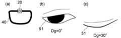
図14(a)に表わしたように、撮像部20は、保持部40の側部に設けられても良い。この場合、撮像部20は、観視者50の横側から眼51を撮像する。図14(a)及び図14(c)は、図14(a)の状態において眼51を撮像した画像を例示している。図14(b)は、視線方向Dgが0°方向である状態の眼51の画像であり、図14(c)は、視線方向Dgが30°方向である状態の眼51の画像である。この場合には、例えば、眼の形状、上瞼と下瞼との間の距離D1、又は、上瞼と下瞼との間の角度θを検出することで、視線の方向を検出することができる。 As illustrated in FIG. 14A, the
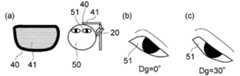
図15(a)に表わしたように、例えば、保持部40に反射部41を設ける。撮像部20は、反射部41に写った眼51の像を撮像しても良い。例えば、眼鏡のレンズに相当する部分に反射部41を設ける。反射部41は、例えば、光反射性である。反射部41には、例えば、ハーフミラーが用いられる。図15(b)及び図15(c)は、図15(a)の状態において眼51を撮像した画像を例示している。図15(b)は、視線方向Dgが0°方向である状態の眼51の画像であり、図15(c)は、視線方向Dgが30°方向である状態の眼51の画像である。この場合には、例えば、眼の形状、上瞼の位置PLz、又は、上瞼と下瞼との間の距離D1を検出することで、視線の方向を検出することができる。例えば、眼51に赤外光を照射し、撮像部20に赤外カメラを用いる。これにより、例えば、反射部41に写った眼51の像をより確実に撮像することができる。 As shown in FIG. 15A, for example, the
例えば、観視者50の眼51の画像において、瞼ではなく瞳の像に基づいて、視線の方向を検出する参考例の表示装置がある。この参考例の表示装置においても、例えば、撮像部が設けられている。撮像部によって観視者の瞳の画像を複数取得し、その画像に基づいて、視線の方向を検出する。しかし、このような参考例の方法においては、確実に瞳を撮像する必要がある。そのため、例えば眼を撮像する撮像部の位置は、瞳を撮像することのできる位置に限定される。瞳を撮像するために、撮像部を移動させる必要が生じる場合もある。 For example, there is a display device of a reference example that detects the direction of the line of sight based on the image of the
これに対して、本実施形態に係る表示装置においては、眼51の瞼の像に基づいて観視者50の視線方向を検出する。これにより、上述のように、撮像部20の配置についての自由度が高い。例えば、参考例の表示装置に比べて、高い精度で視線方向を検出することができる。視線方向を検出しやすい。これにより、より適切な位置に画像を表示することができる。 On the other hand, in the display device according to the present embodiment, the line-of-sight direction of the
図16(a)〜図16(c)は、表示装置の動作を例示する模式図である。
画像表示部10は、検出された視線の方向に基づいて、眼51の位置に対する画像の表示位置を変更する。例えば、駆動部33によって、画像の表示位置が変更される。例えば、駆動部33は、画像表示部10の少なくとも一部(例えば光学部15及び光出射部17)を回転させる。回転の中心軸は、例えば、眼51の位置に対応する。これにより、画像の表示位置と観視者50の視線方向とが調整される。FIG. 16A to FIG. 16C are schematic views illustrating the operation of the display device.
The
図16(a)〜図16(c)は、画像の表示位置と視線方向との関係を例示している。図16(a)は、観視者50の視線方向が0°方向である状態を例示している。図16(a)に表わしたように、画面Pd1(観視者50が知覚する画像の表示面)は、視線方向Dgに対して、例えば、垂直である。すなわち、画像情報を含む光は、例えば、視線方向Dgと平行な方向に進行し、眼51へ入射する。この場合、観視者50の視界内に画面Pd1があれば(観視者50の眼51が画像のアイレンジ内にあれば)、観視者50は、画像の全体を見ることができる。 FIG. 16A to FIG. 16C illustrate the relationship between the image display position and the line-of-sight direction. FIG. 16A illustrates a state in which the viewing direction of the
図16(b)及び図16(c)は、観視者の視線方向が0°方向よりも下側に移動した状態を例示している。このとき、例えば、図16(b)に表わしたように、画像の表示位置(画面Pd1)を、鉛直方向(0°方向に対して垂直な方向)に移動させる。この場合、画像情報を含む光は、例えば、視線方向Dgと交差する方向に進行し、眼51へ入射する。この場合、観視者50の視界内に画面Pd1の全体がなく、観視者50は、画像の全体を見ることができない場合がある。画像のアイレンジ方向が異なり、画面の一部が欠けてしまう場合がある。 FIG. 16B and FIG. 16C exemplify a state in which the viewer's line-of-sight direction has moved below the 0 ° direction. At this time, for example, as shown in FIG. 16B, the image display position (screen Pd1) is moved in the vertical direction (direction perpendicular to the 0 ° direction). In this case, for example, the light including the image information travels in a direction intersecting the line-of-sight direction Dg and enters the
これに対して、実施形態においては、例えば、図16(c)に表わしたように、画像の表示位置(画面Pd1の位置)は、眼51を中心として回転するように調整される。この場合には、例えば、画像情報を含む光が、視線方向とほぼ平行な方向に進行し、眼51へ入射しやすい。これにより、例えば、観視者50は、画像の全体を見ることができる。駆動部33は、例えば、画面Pd1の位置が眼51を中心として回転するように、画像表示部10の少なくとも一部を回転させる。駆動部33は、第1画像から検出された視線方向に基づいて、画像表示部10の少なくとも一部の眼51に対する位置を変更する。 On the other hand, in the embodiment, for example, as shown in FIG. 16C, the image display position (position of the screen Pd <b> 1) is adjusted so as to rotate around the
例えば、画像表示部10の回転中心軸の位置は、眼51の位置でなくても良い。画像表示部10の回転中心軸の位置は、適宜選択することができる。例えば、画像表示部の回転中心軸の位置を、光学部15の中央付近に設けても良い。この場合には、例えば、眼51の中心の位置と、光学部15の中央の位置と、の間の角度に応じた補正が行われる。 For example, the position of the rotation center axis of the
例えば、コンバイナ12の位置を変更することで、画像の表示位置(画面Pd1の位置)を変更しても良い。すなわち、光学部15は、第1画像に基づいて検出された観視者50の視線方向に応じて、眼51の位置に対するコンバイナ12の位置を変更してもよい。これにより、観視者50の視線方向に応じて、画像を表示することができる。 For example, the display position of the image (the position of the screen Pd1) may be changed by changing the position of the
例えば、画像情報を含む光の光路を変更することで、画像の表示位置(画面Pd1の位置)を変更しても良い。すなわち、第1画像に基づいて検出された観視者50の視線方向に応じて、画像情報を含む光の一部が入射するコンバイナにおける位置を変更する。例えば、接眼レンズ13の位置または焦点距離などを変更しても良い。これにより、観視者50の視線方向に応じて、画像を表示することができる。 For example, the display position of the image (the position of the screen Pd1) may be changed by changing the optical path of the light including the image information. That is, the position in the combiner where a part of the light including the image information is incident is changed according to the line-of-sight direction of the
例えば、光出射部17において表示される画像を変更することで、画像の表示位置(画面Pd1の位置)を変更しても良い。例えば、駆動回路30は、第1画像に基づいて、画像情報を変更する。このように、第1画像に基づいて、光出射部17が出射する光を変更しても良い。 For example, the image display position (the position of the screen Pd1) may be changed by changing the image displayed in the
実施形態においては、上述の表示位置の変更方法が、適宜組み合わせて用いられても良い。これにより、観視者50の視線方向に応じて、画像を表示することができる。 In the embodiment, the above-described display position changing methods may be used in appropriate combination. Thereby, an image can be displayed according to the line-of-sight direction of the
実施形態によれば、見やすい表示装置が提供される。 According to the embodiment, an easy-to-see display device is provided.
なお、本願明細書において、「垂直」及び「平行」は、厳密な垂直及び厳密な平行だけではなく、例えばばらつきなどを含むものであり、実質的に垂直及び実質的に平行であれば良い。 In the specification of the present application, “vertical” and “parallel” include not only strict vertical and strict parallel, but also include, for example, variations, and may be substantially vertical and substantially parallel.
以上、具体例を参照しつつ、本発明の実施の形態について説明した。しかし、本発明の実施形態は、これらの具体例に限定されるものではない。例えば、光出射部、光学部、画像表示部、撮像部、処理部、駆動部、保持部などの各要素の具体的な構成に関しては、当業者が公知の範囲から適宜選択することにより本発明を同様に実施し、同様の効果を得ることができる限り、本発明の範囲に包含される。
また、各具体例のいずれか2つ以上の要素を技術的に可能な範囲で組み合わせたものも、本発明の要旨を包含する限り本発明の範囲に含まれる。The embodiments of the present invention have been described above with reference to specific examples. However, embodiments of the present invention are not limited to these specific examples. For example, the specific configuration of each element such as the light emitting unit, the optical unit, the image display unit, the imaging unit, the processing unit, the driving unit, and the holding unit is appropriately selected from a known range by those skilled in the art. Are included in the scope of the present invention as long as they can be carried out in the same manner and the same effects can be obtained.
Moreover, what combined any two or more elements of each specific example in the technically possible range is also included in the scope of the present invention as long as the gist of the present invention is included.
その他、本発明の実施の形態として上述した表示装置及び視線推定装置を基にして、当業者が適宜設計変更して実施し得る全ての表示装置及び視線推定装置も、本発明の要旨を包含する限り、本発明の範囲に属する。 In addition, all display devices and line-of-sight estimation devices that can be implemented by those skilled in the art based on the display device and line-of-sight estimation device described above as embodiments of the present invention also encompass the gist of the present invention. As long as it belongs to the scope of the present invention.
その他、本発明の思想の範疇において、当業者であれば、各種の変更例及び修正例に想到し得るものであり、それら変更例及び修正例についても本発明の範囲に属するものと了解される。 In addition, in the category of the idea of the present invention, those skilled in the art can conceive of various changes and modifications, and it is understood that these changes and modifications also belong to the scope of the present invention. .
本発明のいくつかの実施形態を説明したが、これらの実施形態は、例として提示したものであり、発明の範囲を限定することは意図していない。これら新規な実施形態は、その他の様々な形態で実施されることが可能であり、発明の要旨を逸脱しない範囲で、種々の省略、置き換え、変更を行うことができる。これら実施形態やその変形は、発明の範囲や要旨に含まれるとともに、特許請求の範囲に記載された発明とその均等の範囲に含まれる。 Although several embodiments of the present invention have been described, these embodiments are presented by way of example and are not intended to limit the scope of the invention. These novel embodiments can be implemented in various other forms, and various omissions, replacements, and changes can be made without departing from the scope of the invention. These embodiments and modifications thereof are included in the scope and gist of the invention, and are included in the invention described in the claims and the equivalents thereof.
10…画像表示部、 12…コンバイナ、 13…接眼レンズ、 15…光学部、 17…光出射部、 20…撮像部、 30…駆動回路、 32…通信部、 33…駆動部、 35…処理部、 40…保持部、 41…反射部、 50…観視者、 51…眼(眼球)、 100…表示装置、 200…視線推定装置、 D1…距離、 Dg…視線方向、 ELd…下瞼、 ELu…上瞼、 Ep…瞳、 P1…画像、 Pd1…画面、 PLz…位置、 Pr2、Pr3…画像、 Pu0、Pu30…位置、 S1〜S7…ステップ1〜7、 SAD…差、 g1、g2…注視点 DESCRIPTION OF
Claims (17)
Translated fromJapanese画像表示部であって、
画像情報を含む光を出射する光出射部と、
前記光が入射し、前記光の少なくとも一部の光を前記観視者の眼球へ入射させるコンバイナを含む光学部と、
を含み、前記撮像部で撮像された前記第1画像に基づいて、前記少なくとも一部の前記光の前記眼球に対する入射方向を変更する画像表示部と、
を備えた表示装置。An imaging unit that captures the first image in the first state of the eyelid of the viewer;
An image display unit,
A light emitting unit that emits light including image information;
An optical unit including a combiner that causes the light to enter, and causes at least part of the light to enter the eyeball of the viewer;
An image display unit that changes an incident direction of the at least part of the light with respect to the eyeball based on the first image captured by the imaging unit;
A display device comprising:
前記画像表示部は、推定された視線の前記方向に沿った方向に前記入射方向を変更する請求項1記載の表示装置。A processing unit for estimating a direction of the line of sight of the viewer in the first state based on the first image;
The display device according to claim 1, wherein the image display unit changes the incident direction to a direction along the direction of the estimated line of sight.
前記第2状態における前記観視者の視線は、前記第3状態における前記観視者の視線よりも上側を向いている請求項3または4に記載の表示装置。The line of sight of the viewer in the third state faces the lower side of the viewer,
5. The display device according to claim 3, wherein the line of sight of the viewer in the second state faces upward from the line of sight of the viewer in the third state.
前記駆動部は、前記第1画像に基づいて、前記画像表示部の前記眼球に対する位置を変更する請求項1〜6のいずれか1つに記載の表示装置。The image display unit further includes a drive unit,
The display device according to claim 1, wherein the drive unit changes a position of the image display unit with respect to the eyeball based on the first image.
前記駆動回路は、前記第1画像に基づいて、前記画像情報を変更する請求項1〜10のいずれか1つに記載の表示装置。A drive circuit for controlling the light emitting section;
The display device according to claim 1, wherein the drive circuit changes the image information based on the first image.
前記保持部は、前記画像表示部と前記眼球との間の空間的配置を規定する請求項1〜11のいずれか1つに記載の表示装置。A holding unit for holding the image display unit;
The display device according to claim 1, wherein the holding unit defines a spatial arrangement between the image display unit and the eyeball.
前記第1画像に基づいて、前記第1状態における前記観視者の視線の方向を推定する処理部と、
を備えた視線推定装置。An imaging unit that captures the first image in the first state of the eyelid of the viewer;
A processing unit that estimates a direction of the line of sight of the viewer in the first state based on the first image;
A gaze estimation apparatus.
前記第2状態における前記観視者の視線は、前記第3状態における前記観視者の視線よりも上側を向いている請求項14または15に記載の視線推定装置。The line of sight of the viewer in the third state faces the lower side of the viewer,
The line-of-sight estimation apparatus according to claim 14 or 15, wherein the line of sight of the viewer in the second state faces upward from the line of sight of the viewer in the third state.
Priority Applications (2)
| Application Number | Priority Date | Filing Date | Title |
|---|---|---|---|
| JP2014014053AJP5956479B2 (en) | 2014-01-29 | 2014-01-29 | Display device and gaze estimation device |
| US14/607,430US9823743B2 (en) | 2014-01-29 | 2015-01-28 | Devices for estimating gaze based on a state of an eyelid of a viewer |
Applications Claiming Priority (1)
| Application Number | Priority Date | Filing Date | Title |
|---|---|---|---|
| JP2014014053AJP5956479B2 (en) | 2014-01-29 | 2014-01-29 | Display device and gaze estimation device |
Publications (2)
| Publication Number | Publication Date |
|---|---|
| JP2015141312Atrue JP2015141312A (en) | 2015-08-03 |
| JP5956479B2 JP5956479B2 (en) | 2016-07-27 |
Family
ID=53678992
Family Applications (1)
| Application Number | Title | Priority Date | Filing Date |
|---|---|---|---|
| JP2014014053AExpired - Fee RelatedJP5956479B2 (en) | 2014-01-29 | 2014-01-29 | Display device and gaze estimation device |
Country Status (2)
| Country | Link |
|---|---|
| US (1) | US9823743B2 (en) |
| JP (1) | JP5956479B2 (en) |
Cited By (11)
| Publication number | Priority date | Publication date | Assignee | Title |
|---|---|---|---|---|
| JP2018027290A (en)* | 2016-08-18 | 2018-02-22 | エーエーシーアコースティックテクノロジーズ(シンセン)カンパニーリミテッドAAC Acoustic Technologies(Shenzhen)Co.,Ltd | Virtual reality device with iris information collection function |
| JP2018036608A (en)* | 2016-09-02 | 2018-03-08 | 株式会社テレパシージャパン | Ocular image display device with transparent substrate |
| JP2018523878A (en)* | 2015-08-21 | 2018-08-23 | マジック リープ, インコーポレイテッドMagic Leap,Inc. | Eyelid shape estimation |
| KR20180112754A (en)* | 2015-11-06 | 2018-10-12 | 아큘러스 브이알, 엘엘씨 | Eye tracking using optical flow |
| JP2018530781A (en)* | 2015-09-23 | 2018-10-18 | マジック リープ, インコーポレイテッドMagic Leap,Inc. | Eye imaging using off-axis imager |
| WO2020241283A1 (en)* | 2019-05-28 | 2020-12-03 | ソニー株式会社 | Wearable display device |
| WO2021112282A1 (en)* | 2019-12-04 | 2021-06-10 | 서울대학교산학협력단 | Gaze tracking device using pupil detection and eyelid-line curvature, and method therefor |
| US11126842B2 (en) | 2015-10-16 | 2021-09-21 | Magic Leap, Inc. | Eye pose identification using eye features |
| JPWO2021255632A1 (en)* | 2020-06-15 | 2021-12-23 | ||
| US11538280B2 (en) | 2015-08-21 | 2022-12-27 | Magic Leap, Inc. | Eyelid shape estimation using eye pose measurement |
| JP2024507811A (en)* | 2021-02-19 | 2024-02-21 | アップル インコーポレイテッド | User interface and device settings based on user identification |
Families Citing this family (1)
| Publication number | Priority date | Publication date | Assignee | Title |
|---|---|---|---|---|
| WO2021087297A1 (en)* | 2019-10-31 | 2021-05-06 | Terumo Cardiovascular Systems Corporation | Heart-lung machine with augmented reality display |
Citations (5)
| Publication number | Priority date | Publication date | Assignee | Title |
|---|---|---|---|---|
| JPH1195158A (en)* | 1997-09-22 | 1999-04-09 | Minolta Co Ltd | Video observation device |
| JP2004133749A (en)* | 2002-10-11 | 2004-04-30 | Tokai Rika Co Ltd | Face direction detector |
| JP2006105889A (en)* | 2004-10-08 | 2006-04-20 | Canon Inc | Eye detection device and image display device |
| JP2007537610A (en)* | 2004-05-11 | 2007-12-20 | エルビット・システムズ・リミテッド | Audiovisual communication improvement method and system |
| WO2012172719A1 (en)* | 2011-06-16 | 2012-12-20 | パナソニック株式会社 | Head-mounted display and misalignment correction method thereof |
Family Cites Families (9)
| Publication number | Priority date | Publication date | Assignee | Title |
|---|---|---|---|---|
| US7626569B2 (en)* | 2004-10-25 | 2009-12-01 | Graphics Properties Holdings, Inc. | Movable audio/video communication interface system |
| US7542210B2 (en)* | 2006-06-29 | 2009-06-02 | Chirieleison Sr Anthony | Eye tracking head mounted display |
| JP2008176096A (en) | 2007-01-19 | 2008-07-31 | Brother Ind Ltd | Image display device |
| JP2009134276A (en)* | 2007-11-05 | 2009-06-18 | Panasonic Corp | Display device, display method, display program, integrated circuit, glasses-type head mounted display, automobile, monocular, and stationary display |
| US8998414B2 (en)* | 2011-09-26 | 2015-04-07 | Microsoft Technology Licensing, Llc | Integrated eye tracking and display system |
| US8970452B2 (en)* | 2011-11-02 | 2015-03-03 | Google Inc. | Imaging method |
| US9001030B2 (en)* | 2012-02-15 | 2015-04-07 | Google Inc. | Heads up display |
| US9116545B1 (en)* | 2012-03-21 | 2015-08-25 | Hayes Solos Raffle | Input detection |
| US9128522B2 (en)* | 2012-04-02 | 2015-09-08 | Google Inc. | Wink gesture input for a head-mountable device |
- 2014
- 2014-01-29JPJP2014014053Apatent/JP5956479B2/ennot_activeExpired - Fee Related
- 2015
- 2015-01-28USUS14/607,430patent/US9823743B2/ennot_activeExpired - Fee Related
Patent Citations (5)
| Publication number | Priority date | Publication date | Assignee | Title |
|---|---|---|---|---|
| JPH1195158A (en)* | 1997-09-22 | 1999-04-09 | Minolta Co Ltd | Video observation device |
| JP2004133749A (en)* | 2002-10-11 | 2004-04-30 | Tokai Rika Co Ltd | Face direction detector |
| JP2007537610A (en)* | 2004-05-11 | 2007-12-20 | エルビット・システムズ・リミテッド | Audiovisual communication improvement method and system |
| JP2006105889A (en)* | 2004-10-08 | 2006-04-20 | Canon Inc | Eye detection device and image display device |
| WO2012172719A1 (en)* | 2011-06-16 | 2012-12-20 | パナソニック株式会社 | Head-mounted display and misalignment correction method thereof |
Cited By (23)
| Publication number | Priority date | Publication date | Assignee | Title |
|---|---|---|---|---|
| JP2022051873A (en)* | 2015-08-21 | 2022-04-01 | マジック リープ, インコーポレイテッド | Eyelid shape estimation |
| JP2018523878A (en)* | 2015-08-21 | 2018-08-23 | マジック リープ, インコーポレイテッドMagic Leap,Inc. | Eyelid shape estimation |
| US11538280B2 (en) | 2015-08-21 | 2022-12-27 | Magic Leap, Inc. | Eyelid shape estimation using eye pose measurement |
| JP7671795B2 (en) | 2015-09-23 | 2025-05-02 | マジック リープ, インコーポレイテッド | Eye imaging using an off-axis imager |
| US12228738B2 (en) | 2015-09-23 | 2025-02-18 | Magic Leap, Inc. | Eye imaging with an off-axis imager |
| JP2018530781A (en)* | 2015-09-23 | 2018-10-18 | マジック リープ, インコーポレイテッドMagic Leap,Inc. | Eye imaging using off-axis imager |
| US11747624B2 (en) | 2015-09-23 | 2023-09-05 | Magic Leap, Inc. | Eye imaging with an off-axis imager |
| US11022801B2 (en) | 2015-09-23 | 2021-06-01 | Magic Leap, Inc. | Eye imaging with an off-axis imager |
| JP2023076541A (en)* | 2015-09-23 | 2023-06-01 | マジック リープ, インコーポレイテッド | Imaging the eye with an off-axis imager |
| US11749025B2 (en) | 2015-10-16 | 2023-09-05 | Magic Leap, Inc. | Eye pose identification using eye features |
| US11126842B2 (en) | 2015-10-16 | 2021-09-21 | Magic Leap, Inc. | Eye pose identification using eye features |
| KR101953704B1 (en) | 2015-11-06 | 2019-03-04 | 페이스북 테크놀로지스, 엘엘씨 | Eye tracking using optical flow |
| KR20180112754A (en)* | 2015-11-06 | 2018-10-12 | 아큘러스 브이알, 엘엘씨 | Eye tracking using optical flow |
| JP2018027290A (en)* | 2016-08-18 | 2018-02-22 | エーエーシーアコースティックテクノロジーズ(シンセン)カンパニーリミテッドAAC Acoustic Technologies(Shenzhen)Co.,Ltd | Virtual reality device with iris information collection function |
| JP2018036608A (en)* | 2016-09-02 | 2018-03-08 | 株式会社テレパシージャパン | Ocular image display device with transparent substrate |
| WO2020241283A1 (en)* | 2019-05-28 | 2020-12-03 | ソニー株式会社 | Wearable display device |
| US12339451B2 (en) | 2019-05-28 | 2025-06-24 | Sony Group Corporation | Wearable display device |
| WO2021112282A1 (en)* | 2019-12-04 | 2021-06-10 | 서울대학교산학협력단 | Gaze tracking device using pupil detection and eyelid-line curvature, and method therefor |
| JPWO2021255632A1 (en)* | 2020-06-15 | 2021-12-23 | ||
| JP2024507811A (en)* | 2021-02-19 | 2024-02-21 | アップル インコーポレイテッド | User interface and device settings based on user identification |
| JP7607143B2 (en) | 2021-02-19 | 2024-12-26 | アップル インコーポレイテッド | User interface and device settings based on user identity |
| JP2025076420A (en)* | 2021-02-19 | 2025-05-15 | アップル インコーポレイテッド | User interface and device settings based on user identity |
| JP7746516B2 (en) | 2021-02-19 | 2025-09-30 | アップル インコーポレイテッド | User interface and device settings based on user identity |
Also Published As
| Publication number | Publication date |
|---|---|
| JP5956479B2 (en) | 2016-07-27 |
| US9823743B2 (en) | 2017-11-21 |
| US20150212577A1 (en) | 2015-07-30 |
Similar Documents
| Publication | Publication Date | Title |
|---|---|---|
| JP5956479B2 (en) | Display device and gaze estimation device | |
| US12073015B1 (en) | Systems and methods for calibrating eye tracking | |
| CN110321773B (en) | Neural network training for three-dimensional (3D) gaze prediction using calibration parameters | |
| US11500607B2 (en) | Using detected pupil location to align optical components of a head-mounted display | |
| CN112470163B (en) | In-field illumination and imaging for eye tracking | |
| US8736692B1 (en) | Using involuntary orbital movements to stabilize a video | |
| US9711114B1 (en) | Display apparatus and method of displaying using projectors | |
| US9285872B1 (en) | Using head gesture and eye position to wake a head mounted device | |
| KR20230076815A (en) | How to drive a light source in a near eye display | |
| CN111602082B (en) | Position Tracking System for Head Mounted Displays Including Sensor Integrated Circuits | |
| CN110320998B (en) | Training of neural networks for 3D gaze prediction | |
| US9092671B2 (en) | Visual line detection device and visual line detection method | |
| US9355314B2 (en) | Head-mounted display apparatus and login method thereof | |
| US11353955B1 (en) | Systems and methods for using scene understanding for calibrating eye tracking | |
| JP5420793B1 (en) | Head-mounted display with adjustable image viewing distance | |
| CN107562184A (en) | Image display system, image display method, image show program | |
| US10789782B1 (en) | Image plane adjustment in a near-eye display | |
| US10488917B2 (en) | Gaze-tracking system and method of tracking user's gaze using reflective element | |
| JP7081599B2 (en) | Information processing equipment, information processing methods, and programs | |
| US20210357027A1 (en) | Electronic device and control method thereof | |
| US9265415B1 (en) | Input detection | |
| US20200033613A1 (en) | Display apparatus and method of displaying using curved optical combiner | |
| KR20220128726A (en) | Head-worn display device, operating method in the device, and storage medium | |
| KR20240030881A (en) | Method for outputting a virtual content and an electronic device supporting the same | |
| JP2015055869A (en) | Virtual image display device |
Legal Events
| Date | Code | Title | Description |
|---|---|---|---|
| A131 | Notification of reasons for refusal | Free format text:JAPANESE INTERMEDIATE CODE: A131 Effective date:20151027 | |
| A977 | Report on retrieval | Free format text:JAPANESE INTERMEDIATE CODE: A971007 Effective date:20151028 | |
| A521 | Written amendment | Free format text:JAPANESE INTERMEDIATE CODE: A523 Effective date:20151221 | |
| TRDD | Decision of grant or rejection written | ||
| A01 | Written decision to grant a patent or to grant a registration (utility model) | Free format text:JAPANESE INTERMEDIATE CODE: A01 Effective date:20160518 | |
| A61 | First payment of annual fees (during grant procedure) | Free format text:JAPANESE INTERMEDIATE CODE: A61 Effective date:20160616 | |
| R151 | Written notification of patent or utility model registration | Ref document number:5956479 Country of ref document:JP Free format text:JAPANESE INTERMEDIATE CODE: R151 | |
| LAPS | Cancellation because of no payment of annual fees |