JP2015132250A - Engine silencer with supercharger - Google Patents
Engine silencer with superchargerDownload PDFInfo
- Publication number
- JP2015132250A JP2015132250AJP2014005552AJP2014005552AJP2015132250AJP 2015132250 AJP2015132250 AJP 2015132250AJP 2014005552 AJP2014005552 AJP 2014005552AJP 2014005552 AJP2014005552 AJP 2014005552AJP 2015132250 AJP2015132250 AJP 2015132250A
- Authority
- JP
- Japan
- Prior art keywords
- silencer
- supercharger
- pipe
- engine
- connection
- Prior art date
- Legal status (The legal status is an assumption and is not a legal conclusion. Google has not performed a legal analysis and makes no representation as to the accuracy of the status listed.)
- Pending
Links
- 230000003584silencerEffects0.000titleclaimsabstractdescription95
- 239000000463materialSubstances0.000claimsabstractdescription25
- 239000007779soft materialSubstances0.000claimsabstractdescription11
- 230000008878couplingEffects0.000claimsabstractdescription6
- 238000010168coupling processMethods0.000claimsabstractdescription6
- 238000005859coupling reactionMethods0.000claimsabstractdescription6
- 230000002093peripheral effectEffects0.000claimsdescription10
- 238000003466weldingMethods0.000claimsdescription6
- 238000000465mouldingMethods0.000claimsdescription5
- 229920001971elastomerPolymers0.000abstractdescription14
- 229920002725thermoplastic elastomerPolymers0.000description4
- 230000000694effectsEffects0.000description3
- 229920001707polybutylene terephthalatePolymers0.000description3
- 239000004743PolypropyleneSubstances0.000description2
- 150000002148estersChemical class0.000description2
- -1polypropylenePolymers0.000description2
- 239000000853adhesiveSubstances0.000description1
- 230000001070adhesive effectEffects0.000description1
- 239000000806elastomerSubstances0.000description1
- 230000030279gene silencingEffects0.000description1
- 239000012535impuritySubstances0.000description1
- 230000037431insertionEffects0.000description1
- 238000003780insertionMethods0.000description1
- 230000010354integrationEffects0.000description1
- 229920002647polyamidePolymers0.000description1
- 229920001155polypropylenePolymers0.000description1
- 239000011347resinSubstances0.000description1
- 229920005989resinPolymers0.000description1
- 238000007789sealingMethods0.000description1
- 239000003566sealing materialSubstances0.000description1
Images


Landscapes
- Supercharger (AREA)
Abstract
Description
Translated fromJapanese本発明は、過給器付きエンジンに用いられる消音器に関する。 The present invention relates to a silencer used for an engine with a supercharger.
図4に示すように、過給器付きエンジンの、過給器5aとインタークーラー5bとをつなぐ配管5cに消音器1を配設する場合、消音器1と配管5cとの間を柔軟性を有するゴムホース3で繋ぎ、クランプ4で締め付けることが行なわれる。ゴムホース3は、消音器1および配管5cとは別体であり、各端部が消音器1と配管5cの端部1a、5c−aの外周部にそれぞれ嵌装されている。 As shown in FIG. 4, when the silencer 1 is disposed in the
しかし、従来の過給器付きエンジン用消音器には、つぎの問題点がある。
(a)消音器1および配管5cとは別体のゴムホース3を有するため、コストアップの要因となっている。詳しくは、(a−1)ゴムホース3は、柔軟性を有しており、過給器5aの過給圧に耐えるためにメッシュ状になった糸を挟み込んだ構造となっており、比較的高価である。そのため、コストアップの要因となっている。また、(a−2)ゴムホース3の各端部を消音器1と配管5cの端部1a、5c−aにそれぞれ嵌装させて、それぞれクランプ4で締め付けているため、部品点数が多く組付け点数も多くコストアップの要因となっている。
(b)ゴムホース3と消音器1および配管5cとの結合部には、結合状態を維持するためにそれぞれ35mm程度の差込(ラップ代)が必要であり、ゴムホース3の両側で70mm以上の直線部が必要になる。そのため、限られたエンジンルーム内での配置スペースの確保が困難である。However, the conventional engine silencer with a supercharger has the following problems.
(A) Since the silencer 1 and the
(B) The joint between the
本発明の目的は、消音器および配管とは別体のゴムホースを廃止できる、過給器付きエンジン用消音器を提供することにある。 The objective of this invention is providing the silencer for engines with a supercharger which can abolish a rubber hose separate from a silencer and piping.
上記目的を達成する本発明はつぎの通りである。
(1) 過給器付きエンジンの、過給器とインタークーラーとをつなぐ配管に設けられる消音器であって、
前記消音器は、消音器本体部と、該消音器本体部を前記配管に結合するための接続部と、を備えており、
前記消音器本体部は、ハード材で構成されており、
前記接続部は、ソフト材で構成されており前記消音器本体部に一体化されている、過給器付きエンジン用消音器。
(2) 前記接続部は、前記消音器本体部に二色成形または溶着により一体化されている、(1)記載の過給器付きエンジン用消音器。
(3) 前記接続部は、前記配管の軸方向端部の外周部に嵌装されており外周側からクランプにて前記配管に向かって締め付けられている、(1)または(2)記載の過給器付きエンジン用消音器。The present invention for achieving the above object is as follows.
(1) A silencer provided in a pipe connecting a supercharger and an intercooler of an engine with a supercharger,
The silencer includes a silencer body part, and a connection part for coupling the silencer body part to the pipe,
The silencer main body is composed of a hard material,
The said connection part is a silencer for engines with a supercharger comprised with the soft material and integrated with the said silencer main-body part.
(2) The engine silencer with a supercharger according to (1), wherein the connection portion is integrated with the silencer main body portion by two-color molding or welding.
(3) The connecting portion is fitted to an outer peripheral portion of an end portion in the axial direction of the pipe, and is clamped from the outer peripheral side toward the pipe by a clamp. Engine silencer with feeder.
上記(1)の過給器付きエンジン用消音器によれば、消音器が、消音器本体部と、消音器本体部を配管に結合するための接続部と、を備えており、接続部がソフト材で構成されており消音器本体部に一体化されているため、つぎの効果を得ることができる。
消音器の接続部に従来のゴムホースと同様な接続機能を持たせることができる。そのため、従来要していたゴムホースを廃止できる。そのため、従来に比べて、部品点数を削減でき組付工数の低減を図ることができる。
また、接続部が消音器本体部に一体化されているため、接続部を消音器本体部に嵌装させてクランプ締め付けする構造は不要になり、接続部を配管に結合するだけで済む。そのため、結合個所が従来に比べて半分に減るため、結合のために要する直線部の長さが従来に比べて短く(略半分に)なり、消音器のための配置スペースの確保が従来に比べて容易になる。According to the engine silencer with a supercharger of the above (1), the silencer includes a silencer main body portion and a connection portion for coupling the silencer main body portion to the pipe, and the connection portion is Since it is composed of a soft material and integrated with the silencer body, the following effects can be obtained.
The connection part of the silencer can have a connection function similar to that of a conventional rubber hose. Therefore, the rubber hose which has been required conventionally can be eliminated. Therefore, the number of parts can be reduced and the number of assembling steps can be reduced as compared with the conventional case.
Moreover, since the connection part is integrated with the silencer body part, a structure for fitting the connection part to the silencer body part and clamping it becomes unnecessary, and it is only necessary to couple the connection part to the pipe. As a result, the number of joints is reduced by half compared to the conventional case, so the length of the straight line portion required for connection is shorter (substantially halved) than in the conventional case, and the arrangement space for the silencer is secured compared to the conventional case. Easier.
上記(2)の過給器付きエンジン用消音器によれば、接続部が、消音器本体部に二色成形または溶着により一体化されているため、接続部の消音器本体部への一体化を確実なものとすることができる。 According to the engine silencer with a supercharger of (2) above, since the connection portion is integrated with the silencer main body portion by two-color molding or welding, the connection portion is integrated into the silencer main body portion. Can be ensured.
上記(3)の過給器付きエンジン用消音器によれば、接続部が、配管の軸方向端部の外周部に嵌装されており外周側からクランプにて配管に向かって締め付けられているため、クランプを要しない場合に比べて接続部と配管との結合を確実なものとすることができる。 According to the engine silencer with a supercharger of (3) above, the connecting portion is fitted to the outer peripheral portion of the axial end portion of the pipe, and is tightened toward the pipe by the clamp from the outer peripheral side. Therefore, the connection between the connecting portion and the pipe can be ensured as compared with the case where no clamp is required.
以下に、本発明実施例の過給器付きエンジン用消音器を、図面を参照して、説明する。
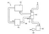
本発明実施例の消音器10は、過給器付きエンジン60に設けられる。過給器付きエンジン60は、図3に示すように、エンジン本体61と、過給器62と、インタークーラー63と、を備える。インレット64から吸気系に取り入れられた空気は、図3の矢印にて示されるように、エアクリーナ65にて不純物除去等が行なわれた後、過給器62を通って昇圧・昇温され、インタークーラー63にて温度が低下されてエンジン本体61に導入される。また、エンジン本体61からの排気は、過給器62を通りエネルギーの一部が吸気系空気の昇圧に利用されて車外に排出される。Hereinafter, an engine silencer with a supercharger according to an embodiment of the present invention will be described with reference to the drawings.
The
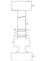
消音器10は、樹脂製であり、過給器付きエンジン60の、過給器62とインタークーラー63とを繋ぐ配管(チューブ)66に設けられる。消音器10の種類は、とくに限定されるものではなく、共鳴型であってもよく、サイドブランチ型であってもよく、拡張型であってもよい。消音器10は、図2に示すように、消音器本体部11と、消音器本体部11を配管66に結合する(繋ぐ)ための接続部12と、を備える。 The
消音器本体部11は、消音機能を有する部分である。消音器本体部11は、射出成形品であり、一部品構成であってもよく互いに溶着等により一体化される複数部品構成であってもよい。消音器本体部11は、消音機能を確保するためにハード材(硬質材)のみで構成されている。ハード材は、過給器付きエンジン60の環境(ターボの環境)に耐えうるため、エアクリーナホースに使われているようなPP(ポリプロピレン)系材料ではなく、耐熱性、剛性の比較的高い、PBT(ポリブチレンテレフタレート)、PA(ポリアミド)系材料、もしくは同等以上の材料である。 The
接続部12は、消音器本体部11と配管66との間を繋ぐ。そのため、本発明図示例のように、消音器本体部11が配管66の過給器62側端部に設けられており過給器62に一側にて直接締結固定される場合、接続部12は、消音器本体部11と過給器62との間には設けられておらず、消音器本体部11の他側と配管66との間にのみ設けられる。なお、図示はしないが、消音器本体部11が配管66の軸方向(延び方向)中間部に設けられており消音器本体部11の両側に配管66が存在する場合には、接続部12は、消音器本体部11の両側に設けられる。 The
接続部12は、消音器本体部11に一体化(固定)されており、配管66に結合(嵌装)されている。接続部12は、配管66に結合されるため、消音器本体部11の材料(ハード材)よりも軟質のソフト材(軟質材、エラストマ)のみで構成されている。ソフト材は、消音器本体部11への一体化を可能にするために、消音器本体部11の材料(ハード材)と同種の材料である。すなわち、消音器本体部11の材料(ハード材)がPA系材料である場合、接続部12の材料(ソフト材)もPA系であり、消音器本体部11の材料(ハード材)がPBTである場合、接続部12の材料(ソフト材)も同じエステル系のTPE(熱可塑性エラストマ)である。なお、消音器本体部11と接続部12との結合強度確保の点では、消音器本体部11の材料(ハード材)がPBTで、接続部12の材料(ソフト材)が同じエステル系のTPE(熱可塑性エラストマ)であることが望ましい。 The
接続部12は、消音器本体部11に二色成形または溶着により一体化されている。なお、接着剤を用いて接続部12を消音器本体部11に固定することは、過給器付きエンジン60の環境(ターボの環境)に耐えることができないため、不可能である。また、ビスやボルト等を用いて締結固定することは、一体化とはいえないものである。 The
接続部12は、消音器本体部11から配管66側に延びており、少なくとも延び方向先端部が配管66の軸方向(延び方向)端部66aの外周部に嵌装されている。接続部12と配管66との間のシール性確保のために、接続部12および配管66とは別体のガスケットやOリング等からなるシール材70が、少なくとも1個、接続部12と配管66との間に設けられていてもよい。また、接続部12が配管66から抜けることを防止するために、接続部12の外周側にクランプ71を設け、該クランプ71にて接続部12を配管66に向かって締め付けるようになっていてもよい。クランプ71が設けられる場合、クランプ71の種類はとくに限定されるものではなく、締め付け可能なものであれば、SUS製バンドであってもよく、その他のものであってもよい。 The connecting
つぎに、本発明実施例の作用、効果を説明する。
(A)消音器10が、消音器本体部11と、消音器本体部11を配管66に結合するための接続部12と、を備えており、接続部12がソフト材で構成されており消音器本体部11に一体化されているため、つぎの作用、効果を得ることができる。
(A−1)消音器10の接続部12に従来のゴムホースと同様な接続機能を持たせることができる。そのため、従来要していたゴムホースを廃止できる。そのため、従来に比べて、部品点数を削減でき組付工数の低減を図ることができる。
(A−2)また、接続部12が消音器本体部11に一体化されているため、接続部12を消音器本体部11に嵌装させてクランプ締め付けする構造は不要になり、接続部12を配管66に結合するだけで済む。そのため、結合個所が従来に比べて半分に減るため、結合のために要する直線部の長さが従来に比べて短く(略半分に)なり、消音器10のための配置スペースの確保が従来に比べて容易になる。Next, the operation and effect of the embodiment of the present invention will be described.
(A) The
(A-1) The
(A-2) Moreover, since the
(B)接続部12が、消音器本体部11に二色成形または溶着により一体化されているため、接続部12の消音器本体部11への一体化を確実なものとすることができる。(B) Since the
(C)接続部12が、配管66の軸方向端部の外周部に嵌装されており外周側からクランプ71にて配管66に向かって締め付けられているため、クランプ71を要しない場合に比べて接続部12と配管66との結合を確実なものとすることができる。(C) Since the connecting
10 消音器
11 消音器本体部
12 接続部
60 過給器付きエンジン
61 エンジン本体
62 過給器
63 インタークーラー
64 インレット
65 エアクリーナ
66 配管
66a 配管の軸方向端部
70 シール材
71 クランプDESCRIPTION OF
Claims (3)
Translated fromJapanese前記消音器は、消音器本体部と、該消音器本体部を前記配管に結合するための接続部と、を備えており、
前記消音器本体部は、ハード材で構成されており、
前記接続部は、ソフト材で構成されており前記消音器本体部に一体化されている、過給器付きエンジン用消音器。A silencer provided in a pipe connecting the supercharger and the intercooler of an engine with a supercharger,
The silencer includes a silencer body part, and a connection part for coupling the silencer body part to the pipe,
The silencer main body is composed of a hard material,
The said connection part is a silencer for engines with a supercharger comprised with the soft material and integrated with the said silencer main-body part.
Priority Applications (1)
| Application Number | Priority Date | Filing Date | Title |
|---|---|---|---|
| JP2014005552AJP2015132250A (en) | 2014-01-16 | 2014-01-16 | Engine silencer with supercharger |
Applications Claiming Priority (1)
| Application Number | Priority Date | Filing Date | Title |
|---|---|---|---|
| JP2014005552AJP2015132250A (en) | 2014-01-16 | 2014-01-16 | Engine silencer with supercharger |
Publications (1)
| Publication Number | Publication Date |
|---|---|
| JP2015132250Atrue JP2015132250A (en) | 2015-07-23 |
Family
ID=53899633
Family Applications (1)
| Application Number | Title | Priority Date | Filing Date |
|---|---|---|---|
| JP2014005552APendingJP2015132250A (en) | 2014-01-16 | 2014-01-16 | Engine silencer with supercharger |
Country Status (1)
| Country | Link |
|---|---|
| JP (1) | JP2015132250A (en) |
Cited By (1)
| Publication number | Priority date | Publication date | Assignee | Title |
|---|---|---|---|---|
| JP2017080941A (en)* | 2015-10-26 | 2017-05-18 | 小島プレス工業株式会社 | Manufacturing method of two-color molded products |
Citations (7)
| Publication number | Priority date | Publication date | Assignee | Title |
|---|---|---|---|---|
| US2601172A (en)* | 1949-03-31 | 1952-06-17 | Houdaille Hershey Corp | Shock absorbing and silencing mounting arrangement for air cleaners |
| JPS6136173U (en)* | 1984-08-06 | 1986-03-06 | トヨタ自動車株式会社 | Low-noise structure for supercharged engines |
| JP2002070675A (en)* | 2000-08-31 | 2002-03-08 | Suzuki Motor Corp | Intake muffler for engine having supercharger |
| JP2008138687A (en)* | 2008-01-28 | 2008-06-19 | Mitsui Eng & Shipbuild Co Ltd | Installation method of silencer for blower exhaust noise |
| JP2008240727A (en)* | 2007-03-27 | 2008-10-09 | Denso Internatl America Inc | Connection structure for air introduction duct of engine |
| JP2009121248A (en)* | 2007-11-12 | 2009-06-04 | Toyoda Gosei Co Ltd | Resonator and mounting structure the same |
| JP2012193631A (en)* | 2011-03-15 | 2012-10-11 | Toyota Boshoku Corp | Air intake duct |
- 2014
- 2014-01-16JPJP2014005552Apatent/JP2015132250A/enactivePending
Patent Citations (7)
| Publication number | Priority date | Publication date | Assignee | Title |
|---|---|---|---|---|
| US2601172A (en)* | 1949-03-31 | 1952-06-17 | Houdaille Hershey Corp | Shock absorbing and silencing mounting arrangement for air cleaners |
| JPS6136173U (en)* | 1984-08-06 | 1986-03-06 | トヨタ自動車株式会社 | Low-noise structure for supercharged engines |
| JP2002070675A (en)* | 2000-08-31 | 2002-03-08 | Suzuki Motor Corp | Intake muffler for engine having supercharger |
| JP2008240727A (en)* | 2007-03-27 | 2008-10-09 | Denso Internatl America Inc | Connection structure for air introduction duct of engine |
| JP2009121248A (en)* | 2007-11-12 | 2009-06-04 | Toyoda Gosei Co Ltd | Resonator and mounting structure the same |
| JP2008138687A (en)* | 2008-01-28 | 2008-06-19 | Mitsui Eng & Shipbuild Co Ltd | Installation method of silencer for blower exhaust noise |
| JP2012193631A (en)* | 2011-03-15 | 2012-10-11 | Toyota Boshoku Corp | Air intake duct |
Cited By (1)
| Publication number | Priority date | Publication date | Assignee | Title |
|---|---|---|---|---|
| JP2017080941A (en)* | 2015-10-26 | 2017-05-18 | 小島プレス工業株式会社 | Manufacturing method of two-color molded products |
Similar Documents
| Publication | Publication Date | Title |
|---|---|---|
| JP4846616B2 (en) | Hose assembly with clamp and band holder | |
| CN102953876B (en) | Duct for fluid | |
| JP2017530288A (en) | Adaptive air intake sealing joint | |
| CN112814773A (en) | Exhaust pipe structure of internal combustion engine-mounted vehicle and manufacturing method of internal combustion engine-mounted vehicle | |
| US8677750B2 (en) | Turbocharger unit with associated auxiliary component, for an internal combustion engine | |
| JP2004211811A (en) | Pipe connecting structure for connecting tube and hose | |
| JP2763636B2 (en) | Pneumatic transport equipment | |
| JP2015132250A (en) | Engine silencer with supercharger | |
| US8677966B2 (en) | Air intake flow device and system | |
| CN103790693B (en) | A kind of ICS intercooler system air inlet pipe | |
| US9897052B2 (en) | Hose assembly for an engine air intake system | |
| KR20200049964A (en) | Connector For Cooling Pipes Of Vehicle | |
| EP2832984B1 (en) | Flange connection | |
| CN204804945U (en) | Cold intake pipe in car | |
| JP2009203901A (en) | Installing structure of air intake component | |
| KR101452616B1 (en) | Quick-connector for car with easy assembling | |
| EP3112658A1 (en) | Muffler arrangement | |
| JP2017116102A (en) | Connection device between turbine housing of exhaust turbocharger and connection housing | |
| CN211287895U (en) | Sheath structure and engine pipe fitting connection structure | |
| CN219412709U (en) | Differential pressure sensor with integrated structure | |
| CN202832891U (en) | Connecting device used for connecting intake-tube and throttle body of engine | |
| EP2873846A1 (en) | Noise attenuation connection arrangement | |
| JPH089415Y2 (en) | Engine intake system structure | |
| CN217783652U (en) | Air inlet pipe structure of turbocharger | |
| JP2009264180A (en) | Fastening structure for double duct |
Legal Events
| Date | Code | Title | Description |
|---|---|---|---|
| A621 | Written request for application examination | Free format text:JAPANESE INTERMEDIATE CODE: A621 Effective date:20161128 | |
| A977 | Report on retrieval | Free format text:JAPANESE INTERMEDIATE CODE: A971007 Effective date:20170712 | |
| A131 | Notification of reasons for refusal | Free format text:JAPANESE INTERMEDIATE CODE: A131 Effective date:20170725 | |
| A02 | Decision of refusal | Free format text:JAPANESE INTERMEDIATE CODE: A02 Effective date:20180206 |