JP2015130613A - communication system - Google Patents
communication systemDownload PDFInfo
- Publication number
- JP2015130613A JP2015130613AJP2014001628AJP2014001628AJP2015130613AJP 2015130613 AJP2015130613 AJP 2015130613AJP 2014001628 AJP2014001628 AJP 2014001628AJP 2014001628 AJP2014001628 AJP 2014001628AJP 2015130613 AJP2015130613 AJP 2015130613A
- Authority
- JP
- Japan
- Prior art keywords
- slave
- master
- correction
- abnormality
- circuit
- Prior art date
- Legal status (The legal status is an assumption and is not a legal conclusion. Google has not performed a legal analysis and makes no representation as to the accuracy of the status listed.)
- Granted
Links
- 238000004891communicationMethods0.000titleclaimsabstractdescription37
- 238000012937correctionMethods0.000claimsabstractdescription184
- 230000005856abnormalityEffects0.000claimsabstractdescription109
- 230000005540biological transmissionEffects0.000claimsdescription67
- 230000001360synchronised effectEffects0.000abstractdescription3
- 238000001514detection methodMethods0.000description29
- 238000012544monitoring processMethods0.000description28
- 230000002159abnormal effectEffects0.000description4
- 238000000034methodMethods0.000description4
- 239000003990capacitorSubstances0.000description2
- 238000010586diagramMethods0.000description2
- 230000010355oscillationEffects0.000description2
- 239000000919ceramicSubstances0.000description1
- 239000013078crystalSubstances0.000description1
Images


Landscapes
- Small-Scale Networks (AREA)
- Synchronisation In Digital Transmission Systems (AREA)
Abstract
Description
Translated fromJapanese本発明は、マスタに対して複数のスレーブがデイジーチェーン接続されている通信システムに関する。 The present invention relates to a communication system in which a plurality of slaves are daisy chain connected to a master.
マスタに対して複数のスレーブがデイジーチェーン接続されている通信システムが供されている。この種の通信システムの1つとして、マスタが同期タイミングのパルスを所定周期でスレーブ側に送信し、スレーブがマスタ側から送信された同期タイミングのパルスを受信したことに追従してデータをマスタ側に送信する構成がある。この構成では、スレーブに異常(例えばスレーブクロックの異常等)が発生したときには、その異常を速やかに解消することが望まれている。例えば特許文献1には、マスタが同期フレームをスレーブ側に定期的に送信することで、マスタとスレーブとの間でクロックを同期させる手法が開示されている。 There is a communication system in which a plurality of slaves are daisy chain connected to a master. As one of this type of communication system, the master sends the synchronization timing pulse to the slave side in a predetermined cycle, and the slave sends the data to the master side following the reception of the synchronization timing pulse sent from the master side. There is a configuration to send to. In this configuration, when an abnormality (for example, an abnormality of the slave clock) occurs in the slave, it is desired to quickly eliminate the abnormality. For example, Patent Document 1 discloses a technique in which a clock is synchronized between a master and a slave by periodically transmitting a synchronization frame to the slave side.
しかしながら、特許文献1に開示されている手法では、マスタが同期フレームを定期的にしか送信しないので、スレーブに発生した異常に対して即時対応することができない。又、マスタがパルスしか送信しない構成では、マスタが同期フレームを送信することができず、スレーブに発生した異常に対して対応することすらできない。この場合、マスタが同期タイミングのパルスとは別に補正情報を送信する構成が考えられるが、その場合、マスタからの送信が同期タイミングのパルスであるか補正情報であるかをスレーブが識別する必要がある。 However, in the method disclosed in Patent Document 1, since the master transmits the synchronization frame only periodically, it is not possible to immediately cope with the abnormality occurring in the slave. In the configuration in which the master transmits only pulses, the master cannot transmit a synchronization frame, and cannot even cope with an abnormality occurring in the slave. In this case, a configuration in which the master transmits correction information separately from the synchronization timing pulse is conceivable. In this case, the slave needs to identify whether transmission from the master is a synchronization timing pulse or correction information. is there.
本発明は、上記した事情に鑑みてなされたものであり、その目的は、マスタに対して複数のスレーブがデイジーチェーン接続されている構成において、マスタがパルスしか送信しない構成であっても、マスタからの送信が同期タイミングのパルスであるか補正情報であるかをスレーブが識別する必要をなくしつつ、スレーブに発生した異常に対して即時対応することができる通信システムを提供することにある。 The present invention has been made in view of the above-described circumstances, and an object of the present invention is to provide a configuration in which a plurality of slaves are daisy chain connected to a master, even if the master transmits only pulses. It is an object of the present invention to provide a communication system capable of immediately responding to an abnormality occurring in a slave while eliminating the need for the slave to identify whether the transmission from the pulse is a synchronization timing pulse or correction information.
請求項1に記載した発明によれば、マスタは、同期タイミングのパルスを所定周期でスレーブ側に送信する。スレーブは、マスタ側から送信された同期タイミングのパルスを受信したことに追従してデータをマスタ側に送信する。ここで、スレーブは、異常を検出すると、補正要求をマスタ側に送信し、自身が終端以外のスレーブである場合には自身よりも後段のスレーブとの通信を切断する。又、スレーブは、自身よりも後段のスレーブ側から送信された補正要求を受信すると、補正要求をマスタ側に送信する。マスタは、スレーブ側から送信された補正要求を受信すると、補正情報をスレーブ側に送信する。異常を検出したスレーブは、マスタ側から補正情報を受信すると、その受信した補正情報にしたがって当該異常を解消するための補正を実行し、自身が終端以外のスレーブである場合には自身よりも後段のスレーブとの通信を再接続する。又、自身よりも後段のスレーブ側から送信された補正要求を受信したスレーブは、補正要求をマスタ側に送信したことで、これ以降のマスタからの送信が同期タイミングのパルスであるか補正情報であるかを識別する。 According to the first aspect of the present invention, the master transmits a synchronization timing pulse to the slave side at a predetermined period. The slave follows the reception of the synchronization timing pulse transmitted from the master side and transmits data to the master side. Here, when the slave detects an abnormality, the slave transmits a correction request to the master side, and when the slave is a slave other than the terminal, the slave disconnects communication with the slave at the subsequent stage. Further, when the slave receives a correction request transmitted from the slave side subsequent to itself, the slave transmits a correction request to the master side. When the master receives the correction request transmitted from the slave side, the master transmits correction information to the slave side. When the slave that has detected the abnormality receives correction information from the master side, it performs correction to eliminate the abnormality according to the received correction information. Reconnect communication with other slaves. In addition, the slave that has received the correction request transmitted from the slave side downstream from itself transmits the correction request to the master side, so that the subsequent transmission from the master is a pulse of the synchronization timing or the correction information. Identify if there is.
即ち、スレーブは、異常を検出すると、補正要求をマスタ側に送信することで、マスタから補正情報を受信することができる。そして、その異常を検出したスレーブは、その受信した補正情報にしたがって当該異常を解消するための補正を実行することで、異常に対して即時対応することができる。この場合、マスタに対して複数のスレーブがデイジーチェーン接続されている構成では、複数のスレーブは、終端のスレーブと、終端以外のスレーブとに区分され、それらの何れでも異常を検出する可能性がある。 That is, when the slave detects an abnormality, it can receive correction information from the master by transmitting a correction request to the master side. And the slave which detected the abnormality can respond immediately to abnormality by performing the correction | amendment for eliminating the abnormality according to the received correction information. In this case, in a configuration in which a plurality of slaves are connected in a daisy chain to the master, the plurality of slaves are classified into a terminal slave and a slave other than the terminal, and any of them may detect an abnormality. is there.
ここで、異常を検出したスレーブが終端のスレーブである場合、終端以外のスレーブは、その異常を検出した終端のスレーブ側から送信された補正要求を受信してマスタ側に送信する。その結果、終端以外のスレーブは、補正要求を受信してマスタ側に送信したことで、これ以降のマスタからの送信が同期タイミングのパルスであるか補正情報であるかを識別することができる。 Here, when the slave that has detected the abnormality is the terminal slave, the slaves other than the terminal receive the correction request transmitted from the slave at the terminal that has detected the abnormality and transmit the correction request to the master side. As a result, the slaves other than the terminal end can receive the correction request and transmit it to the master side, thereby identifying whether the subsequent transmission from the master is a synchronization timing pulse or correction information.
一方、異常を検出したスレーブが終端以外のスレーブである場合、その異常を検出した終端以外のスレーブよりも前段のスレーブは、その異常を検出した終端以外のスレーブ側から送信された補正要求を受信してマスタ側に送信する。その結果、その異常を検出した終端以外のスレーブよりも前段のスレーブは、補正要求を受信してマスタ側に送信したことで、これ以降のマスタからの送信が同期タイミングのパルスであるか補正情報であるかを識別することができる。しかしながら、その異常を検出した終端以外のスレーブよりも後段のスレーブは、その異常を検出した終端のスレーブから補正要求を受信しない。そのため、その異常を検出した終端以外のスレーブよりも後段のスレーブは、これ以降のマスタからの送信が同期タイミングのパルスであるか補正情報であるかを識別することができない。 On the other hand, if the slave that detected the abnormality is a slave other than the terminal, the slave in the previous stage of the slave other than the terminal that detected the abnormality received the correction request transmitted from the slave side other than the terminal that detected the abnormality. To the master side. As a result, the slave at the previous stage than the slave other than the terminal that detected the abnormality received the correction request and transmitted it to the master side, so that the correction information whether the subsequent transmission from the master is a synchronization timing pulse or not Can be identified. However, a slave at a later stage than the slave other than the terminal that detected the abnormality does not receive a correction request from the slave at the terminal that detected the abnormality. For this reason, a slave subsequent to the slave other than the terminal that has detected the abnormality cannot identify whether the subsequent transmission from the master is a synchronization timing pulse or correction information.
この点に鑑み、本発明では、異常を検出した終端以外のスレーブが、自身よりも後段のスレーブとの通信を切断するようにした。これにより、異常を検出した終端以外のスレーブよりも後段のスレーブにおいて、マスタからの送信が同期タイミングのパルスであるか補正情報であるかを識別する必要をなくすことができる。そして、異常を検出した終端以外のスレーブが、異常を解消するための補正を実行した後に、自身よりも後段のスレーブとの通信を再接続することで、異常を検出する前の状態に速やかに復帰することができる。即ち、スレーブが、マスタ側から送信された同期タイミングのパルスを受信したことに追従してデータをマスタ側に送信することができる。 In view of this point, in the present invention, slaves other than the terminal that detected an abnormality disconnect communication with a slave at a later stage than itself. This eliminates the need to identify whether the transmission from the master is a synchronization timing pulse or correction information in a slave subsequent to the slave other than the terminal that detected the abnormality. Then, after the slaves other than the terminal that detected the abnormality have performed corrections to eliminate the abnormality, the communication with the slave at the subsequent stage is reconnected, so that the state before detecting the abnormality can be promptly restored. Can return. That is, the slave can transmit data to the master side following the reception of the synchronization timing pulse transmitted from the master side.
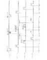
以下、本発明を車両に搭載される通信システムに適用した一実施形態について、図面を参照して説明する。通信システム1は、マスタ2と複数のスレーブ3〜5とがデイジーチェーン接続されて構成されている。スレーブ3〜5は、終端(マスタ2から最も離れている最後段の)以外のスレーブ3、4と、終端のスレーブ5とに区分される。図1では、終端以外のスレーブ3、4が2つの構成を例示しているが、終端以外のスレーブが1つの構成であっても良いし、3つ以上の構成であっても良い。マスタ2は、例えばエアバッグの作動を制御するECU(Electronic Control Unit)である。スレーブ3〜5は、例えばマスタ2がエアバッグの作動を制御するのに必要なデータ(計測したセンサ値、センサ値が正常であるか異常であるかを示す値等)を送信するセンサ等である。 Hereinafter, an embodiment in which the present invention is applied to a communication system mounted on a vehicle will be described with reference to the drawings. The communication system 1 includes a
通信システム1において、マスタ2は、データの取得タイミングを監視しており、データの取得タイミングになると、同期タイミングのパルス(データ送信要求)をスレーブ3〜5側に送信する。スレーブ3〜5は、マスタ2側から送信された同期タイミングのパルスを受信すると、その同期タイミングのパルスの受信を契機とし、それぞれ同期タイミングのパルスの受信から予め設定されている設定時間が経過した後にデータをマスタ2側に送信する。この場合、スレーブ3〜5がそれぞれデータを送信するタイミングが他と重複しないように設定時間を設定することで、それぞれのデータが衝突することなく、マスタ2がそれぞれのデータを混同することなく受信可能となる。マスタ2側からスレーブ3〜5側へのパルスは電圧で送信される。又、スレーブ3〜5側からマスタ2側へのデータや後述する補正要求は電流で送信される。 In the communication system 1, the
マスタ2は、発振器2aと、補正用発振器2bと、補正回路2cと、通常動作回路2dと、補正動作回路2eと、送信回路2fと、受信回路2gと、スレーブ異常検出回路2hとを有する。発振器2aは、コンデンサと抵抗とを含むCR回路から構成される発振器であり、マスタクロックを生成して補正回路2cに出力する(発振する)。補正用発振器2bは、例えば水晶振動子やセラミック振動子から構成される発振器であり、マスタクロックを補正するためのマスタ補正用クロックを生成して補正回路2cに出力する(発振する)。補正用発振器2bが生成するマスタ補正用クロックの発振周波数は発振器2aが生成するマスタクロックの発振周波数よりも精度が高い。 The
補正回路2cは、発振器2aからマスタクロックを入力すると、その入力したマスタクロックを、補正用発振器2bから入力したマスタ補正用クロックに追従するように補正し、その補正後のマスタクロックを発振器2aに出力する。発振器2aは、補正回路2cから補正後のマスタクロックを入力すると、その入力した補正後のマスタクロックを通常動作回路2d及び補正動作回路2eに出力する。 When the master clock is input from the oscillator 2a, the
通常動作回路2dは、データの取得タイミング(監視タイミング)を監視しており、データの取得タイミングになると、同期タイミングのパルスを、発振器2aから入力したマスタクロックと共に送信回路2fに出力する。送信回路2fは、通常動作回路2dから同期タイミングのパルスをマスタクロックと共に入力すると、同期タイミングのパルスをマスタクロックにしたがってスレーブ3〜5側に送信する。受信回路2gは、同期タイミングのパルスが送信回路2fからスレーブ3〜5側に送信されたことに応じて当該スレーブ3〜5側から送信されたデータを受信する。マスタ2は、スレーブ3〜5が異常を検出していない場合には、以上のようにして同期タイミングのパルスをスレーブ3〜5側に送信し、スレーブ3〜5側から送信されたデータを受信する。 The
ここで、マスタ2は、スレーブ3〜5が異常を検出した場合には、以下の動作を行う。受信回路2gは、スレーブ3〜5側から送信された補正要求(スレーブが補正要求を送信する手順については後述する)を受信すると、異常検出をスレーブ異常検出回路2hに出力する。この場合、受信回路2gは、後述するようにスレーブクロックの補正要求、動作電圧の補正要求、送信電流の補正要求を識別可能に受信する。スレーブ異常検出回路2hは、受信回路2gから異常検出を入力すると、その入力した異常検出を通常動作回路2d及び補正動作回路2eに出力する。 Here, when the
補正動作回路2eは、スレーブ異常検出回路2hから異常検出を入力すると、補正情報のパルスを、発振器2aから入力したマスタクロックと共に送信回路2fに出力する。又、通常動作回路2dは、スレーブ異常検出回路2hから異常検出を入力すると、データの取得タイミングになっても、同期タイミングのパルスを送信回路2fに出力しない。送信回路2fは、補正動作回路2eから補正情報のパルスをマスタクロックと共に入力すると、補正情報のパルスをマスタクロックにしたがってスレーブ3〜5側に送信する。この場合、送信回路2fは、スレーブクロックの補正情報のパルス、動作電圧の補正情報のパルス、送信電流の補正情報のパルスを識別可能にスレーブ3〜5側に送信する。マスタ2は、スレーブ3〜5が異常を検出した場合には、以上のようにして補正情報のパルスをスレーブ3〜5側に送信する。 When the abnormality detection is input from the slave
スレーブ3は、発振器3aと、電圧補正回路3bと、電流補正回路3cと、監視回路3dと、受信回路3eと、送信回路3fと、スイッチ回路3gと、補正検出回路3hとを有する。発振器3aは、上記したマスタ2の発振器2aと同様にコンデンサと抵抗とを含むCR回路から構成される発振器であり、スレーブクロックを生成して監視回路3dに出力する(発振する)。電圧補正回路3bは、スレーブ3の動作電圧の電圧値を監視回路3dに出力する。電流補正回路3cは、スレーブ3がデータを送信する際の送信電流の電流値を監視回路3dに出力する。受信回路3eは、マスタ2側から同期タイミングのパルスを受信すると、同期タイミングのパルスを受信した旨を送信回路3fに通知する。送信回路3fは、同期タイミングのパルスを受信した旨が受信回路3eから通知されると、データを、発振器3aから監視回路3dを介して入力したスレーブクロックにしたがってマスタ2側に送信する。スレーブ3は、異常を検出していない場合には、以上のようにしてマスタ2側から同期タイミングのパルスを受信すると、データをマスタ2側に送信する。 The
ここで、スレーブ3は、異常を検出した場合には、以下の動作を行う。監視回路3dは、発振器3aからスレーブクロックを入力すると、その入力したスレーブクロックの例えばロウレベルの時間幅やハイレベルの時間幅を予め設定されている正常幅と比較し、スレーブクロックが正常であるか否かを判定する。監視回路3dは、例えばロウレベルの時間幅やハイレベルの時間幅が正常幅に達していなかったり正常幅を越えていたりし、スレーブクロックの異常を検出すると、スレーブクロックの異常を示す異常検出を送信回路3fに出力する。又、監視回路3dは、電圧補正回路3bから動作電圧の電圧値を入力すると、その電圧値を予め設定されている正常範囲と比較し、その電圧値が正常であるか否かを判定する。監視回路3dは、その電圧値が正常範囲内でなく、動作電圧の異常を検出すると、動作電圧の異常を示す異常検出を送信回路3fに出力する。又、監視回路3dは、電流補正回路3cから送信電流の電流値を入力すると、その電流値を予め設定されている正常範囲と比較し、その電流値が正常であるか否かを判定する。監視回路3dは、その電流値が正常範囲内でなく、送信電流の異常を検出すると、送信電流の異常を示す異常検出を送信回路3fに出力する。即ち、監視回路3は、スレーブクロックの異常、動作電圧の異常、送信電流の異常の何れであるかを識別可能に異常検出を送信回路3fに出力する。又、監視回路3は、異常を検出すると、切替命令をスイッチ回路3gに出力する。 Here, the
送信回路3fは、監視回路3dから異常検出を入力すると、異常が発生した旨を特定し、補正要求を発振器3aから監視回路3dを介して入力したスレーブクロックにしたがってマスタ2側に送信する。この場合、送信回路3fは、監視回路3dから入力した異常検出がスレーブクロックの異常を示す場合には、スレーブクロックの補正要求を送信する。又、送信回路3fは、監視回路3dから入力した異常検出が動作電圧の異常を示す場合には、動作電圧の補正要求を送信する。又、送信回路3fは、監視回路3dから入力した異常検出が送信電流の異常を示す場合には、送信電流の補正要求を送信する。 When an abnormality detection is input from the
スイッチ回路3gは、監視回路3dから切替命令を入力することで、オンオフを切替え、スレーブ3よりも後段のスレーブ4、5との通信の接続又は切断を切替える。即ち、スレーブ3は、スイッチ回路3gがオンの状態(実線にて示す状態)にある場合には、後段のスレーブ4、5との通信を接続し、マスタ2側から受信したパルスの後段のスレーブ4、5側への送信を許可し、後段のスレーブ4、5から受信したデータや補正要求のマスタ2側への送信を許可する。一方、スレーブ3は、スイッチ回路3gがオフの状態(破線にて示す状態)にある場合には、後段のスレーブ4、5との通信を切断し、マスタ2側から受信したパルスの後段のスレーブ4、5側への送信を禁止し、後段のスレーブ4、5から受信したデータや補正要求のマスタ2側への送信を禁止する。 The
受信回路3eは、マスタ2側から補正情報のパルスを受信すると、補正情報を補正検出回路3hに出力する。補正検出回路3hは、受信回路3eから補正情報を入力すると、その補正情報がスレーブクロックの補正を示す補正情報である場合には、補正命令を発振器3aに出力する。又、補正検出回路3hは、その補正情報が動作電圧の補正を示す補正情報である場合には、補正命令を電圧補正回路3bに出力する。又、補正検出回路3hは、その補正情報が送信電流の補正を示す補正情報である場合には、補正命令を電流補正回路3cに出力する。 When receiving the correction information pulse from the
発振器3aは、補正検出回路3hから補正命令を入力すると、スレーブクロックの補正を実行し、補正後のスレーブクロックを監視回路3dに出力する(発振する)。電圧補正回路3bは、補正検出回路3hから補正命令を入力すると、動作電圧の補正を実行し、補正後の動作電圧の電圧値を監視回路3dに出力する。電流補正回路3cは、補正検出回路3hから補正命令を入力すると、送信電流の補正を実行し、補正後の送信電流の電流値を監視回路3dに出力する。スレーブ3は、異常を検出した場合には、以上のようにして補正要求をマスタ2側に送信し、マスタ2側から補正情報のパルスを受信し、異常を解消するための補正を実行することで、検出した異常を解消する。 When receiving a correction command from the
スレーブ3と同じ終端以外のスレーブ4は、上記したスレーブ3と同様の構成である。即ち、スレーブ4は、発振器4aと、電圧補正回路4bと、電流補正回路4cと、監視回路4dと、受信回路4eと、送信回路4fと、スイッチ回路4gと、補正検出回路4hとを有する。これらの各機能ブロック4a〜4hは、スレーブ3の各機能ブロック3a〜3hと同等の機能を有する。一方、スレーブ3とは異なる終端のスレーブ5は、スイッチ回路3gが省略されている点を除いてスレーブ3と同様の構成である。即ち、スレーブ5は、発振器5aと、電圧補正回路5bと、電流補正回路5cと、監視回路5dと、受信回路5eと、送信回路5fと、補正検出回路5hとを有する。これらの各機能ブロック5a〜5f、5hは、スレーブ3の各機能ブロック3a〜3f、3hと同等の機能を有する。 The slave 4 other than the same terminal as the
次に、上記した構成の作用について、図2から図6を参照して説明する。ここでは、
(1)終端以外のスレーブ4がスレーブクロックの異常を検出した場合(図2参照)
(2)終端のスレーブ5がスレーブクロックの異常を検出した場合(図3参照)
について順次説明する。尚、本実施形態では、マスタ2側から送信される同期タイミングのパルスに対し、スレーブ3、スレーブ4、スレーブ5の順序でデータを送信する場合を説明するが、どのような順序でデータを送信しても良い。Next, the operation of the above configuration will be described with reference to FIGS. here,
(1) When the slave 4 other than the terminal detects an abnormality of the slave clock (see FIG. 2)
(2) When the
Will be described sequentially. In this embodiment, the case where data is transmitted in the order of
(1)終端以外のスレーブ4がスレーブクロックの異常を検出した場合
マスタ2は、データの取得タイミングになると、同期タイミングのパルスを送信回路2fからスレーブ3〜5側に送信する(t1参照)。スレーブ3は、マスタ2側から送信された同期タイミングのパルスを受信回路3eにより受信すると、同期タイミングのパルスの受信から予め設定されている設定時間が経過した後に、データをスレーブクロックにしたがって送信回路3fからマスタ2側に送信する(t2参照)。スレーブ3から送信されたデータは、マスタ2に受信される。スレーブ4は、マスタ2側から送信された同期タイミングのパルスをスレーブ3を経由して受信回路4eにより受信すると、同期タイミングのパルスの受信から予め設定されている設定時間が経過した後に、データをスレーブクロックにしたがって送信回路4fからマスタ2側に送信する(t3参照)。スレーブ4から送信されたデータは、スレーブ3を経由してマスタ2に受信される。(1) When the slave 4 other than the terminal detects an abnormality of the slave clock, the
ここで、スレーブ4は、スレーブクロックの異常を監視回路4dにより検出すると、データを送信回路4fからマスタ2側に送信したことに続いて、スレーブクロックの補正要求を送信回路4fからマスタ2側に送信する(t4参照)。スレーブ4から送信されたスレーブクロックの補正要求は、スレーブ3を経由してマスタ2に受信される。 Here, when the slave circuit 4 detects an abnormality of the slave clock by the
スレーブ5は、マスタ2側から送信された同期タイミングのパルスをスレーブ3、4を経由して受信回路5eにより受信すると、同期タイミングのパルスの受信から予め設定されている設定時間が経過した後に、データをスレーブクロックにしたがって送信回路5fからマスタ2側に送信する(t5参照)。スレーブ5から送信されたデータは、スレーブ4、3を経由してマスタ2に受信される。そして、スレーブクロックの異常を検出したスレーブ4は、スレーブ5から受信したデータのマスタ2側への送信を完了すると、切替命令をスイッチ回路4gに出力し、スイッチ回路4gをオンからオフに切替え、後段のスレーブ5との通信を切断する(切り離す)(t6参照)。 When the
マスタ2は、スレーブ3〜5側から送信されたデータを受信回路2gにより受信すると、その受信したデータを処理する。又、マスタ2は、スレーブ4から送信されたスレーブクロックの補正要求を受信回路2gにより受信すると、スレーブクロックの異常を検出し、スレーブクロックの補正情報のパルスを送信回路2fからスレーブ3〜5側に送信する(t7参照)。この場合、マスタ2側から送信されたスレーブクロックの補正情報のパルスは、スレーブ3に受信され、更にスレーブ3を経由してスレーブ4に受信される。一方、スレーブクロックの異常を検出したスレーブ4よりも後段のスレーブ5との通信を切断しているので、そのスレーブクロックの補正情報のパルスがスレーブ3、4を経由してスレーブ5に受信されることはない。 When the
スレーブ3は、スレーブ4から受信したスレーブクロックの補正要求をマスタ2側に送信したことで、マスタ2側から送信されたパルスが、同期タイミングのパルスではなく、スレーブクロックの補正情報のパルスであると識別する。そして、スレーブ3は、マスタ2側から送信されたスレーブクロックの補正情報のパルスを受信回路3eにより受信すると、スレーブクロックの補正を実行しても良いし実行しなくても良い(t8参照)。スレーブクロックの異常を検出したスレーブ4は、マスタ2側から送信されたスレーブクロックの補正情報のパルスを受信回路4eにより受信すると、スレーブクロックの補正を実行する(t9参照)。そして、スレーブ4は、スレーブクロックの補正を完了すると、切替命令をスイッチ回路4gに出力し、スイッチ回路4gをオフからオンに切替え、切断した後段のスレーブ5との通信を再接続する(t10参照)。 Since the
これ以降、マスタ2は、データの取得タイミングになると、同期タイミングのパルスを送信回路2fからスレーブ3〜5側に送信する(t11参照)。スレーブ3〜5は、それぞれマスタ2側から送信された同期タイミングのパルスを受信回路3e〜5eにより受信すると、同期タイミングのパルスの受信から予め設定されている設定時間が経過した後に、データをスレーブクロックにしたがって送信回路3f〜5fからマスタ2側に送信する(t12〜t14参照)。 Thereafter, the
以上に説明した一連の動作を行うことで、終端以外のスレーブ4がスレーブクロックの異常を検出すると、そのスレーブクロックの異常を検出したスレーブ4は、補正要求をマスタ2側に送信することで、マスタ2側から送信された補正情報を受信することができる。そして、そのスレーブクロックの異常を検出したスレーブ4は、その受信した補正情報にしたがってスレーブクロックの補正を実行することで、スレーブクロック異常に対して即時対応することができる。又、スレーブ4よりも前段のスレーブ3は、スレーブ4から補正要求を受信してマスタ2側に送信したことで、これ以降のマスタ2からの送信が同期タイミングのパルスであるか補正情報のパルスであるかを識別することができる。又、スレーブ4よりも後段のスレーブ5との通信を一時的に切断することで、スレーブ4よりも後段のスレーブ5がマスタ2側からのパルスを受信することがなくなる。その結果、マスタ2からの送信が同期タイミングのパルスであるか補正情報のパルスであるかをスレーブ5が識別する必要をなくすことができる。 By performing the series of operations described above, when the slave 4 other than the terminal detects an abnormality of the slave clock, the slave 4 detecting the abnormality of the slave clock transmits a correction request to the
尚、スレーブ4と同じ終端以外のスレーブ3がスレーブクロックの異常を検出した場合も同様である、即ち、スレーブ3は、スレーブクロックの異常を検出し、後段のスレーブ4、5から受信したデータのマスタ2側への送信を完了すると、後段のスレーブ4、5との通信を切断する。そして、スレーブ3は、マスタ2側から送信されたスレーブクロックの補正情報のパルスを受信し、スレーブクロックの補正を完了すると、切断した後段のスレーブ4、5との通信を再接続する。 The same applies when the
(2)終端のスレーブ5がスレーブクロックの異常を検出した場合
スレーブ5は、スレーブクロックの異常を監視回路5dにより検出すると、データを送信回路5fからマスタ2側に送信したことに続いて、スレーブクロックの補正要求を送信回路5fからマスタ2側に送信する(t25参照)。スレーブ5から送信されたスレーブクロックの補正要求は、スレーブ4、3を経由してマスタ2に受信される。この場合、スレーブ5は、終端(自身よりも後段のスレーブが存在しない)であり、スレーブ3、4のスイッチ回路3g、4gに相当する構成を有していないので、これ以降、上記したスレーブ4が行う動作(後段のスレーブ5との通信を切断したり再接続したりする)を行うことはない。(2) When the
この場合、スレーブ3、4は、それぞれスレーブ5から受信したスレーブクロックの補正要求をマスタ2側に送信したことで、マスタ2側から送信されたパルスが、同期タイミングのパルスではなく、スレーブクロックの補正情報のパルスであると識別する。そして、スレーブ3、4は、それぞれマスタ2側から送信されたスレーブクロックの補正情報のパルスを受信回路3e、4eにより受信すると、スレーブクロックの補正を実行しても良いし実行しなくても良い(t27、t28参照)。スレーブクロックの異常を検出したスレーブ5は、マスタ2側から送信されたスレーブクロックの補正情報のパルスを受信回路5eにより受信すると、スレーブクロックの補正を実行する(t29参照)。 In this case, each of the
異常を検出したスレーブ3〜5と、スレーブ3、4のそれぞれのスイッチ回路3g、4gの動作とは、図4に示す関係となる。即ち、異常を検出したスレーブ3、4が、それぞれのスイッチ回路3g、4gのオンオフを切替える。又、以上は、スレーブ3〜5がスレーブクロックの異常を検出した場合を説明したが、スレーブ3〜5が動作電圧の異常を検出した場合には、図5及び図6に示すように、スレーブ3〜5は、動作電圧の補正要求をマスタ2側に送信し、マスタ2は、動作電圧の補正情報のパルスをスレーブ3〜5側に送信し、他は同様の動作を行う(t41〜t54、t61〜t73参照)。又、スレーブ3〜5が送信電流の異常を検出した場合にも、同様の動作を行う。 The
以上に説明したように本実施形態によれば、スレーブ3〜5は、異常を検出すると、補正要求をマスタ2側に送信するようにした。これにより、マスタ2側から補正情報を受信することができ、その受信した補正情報にしたがって当該異常を解消するための補正を実行することで、異常に対して即時対応することができる。又、終端以外のスレーブ3、4が異常を検出した場合には、自身よりも後段のスレーブとの通信を切断するようにした。これにより、異常を検出した終端以外のスレーブ3、4よりも後段のスレーブにおいて、マスタ2からの送信が同期タイミングのパルスであるか補正情報のパルスであるかを識別する必要をなくすことができる。 As described above, according to the present embodiment, when the
又、終端以外のスレーブ3、4が異常を検出した場合には、異常を検出したスレーブ3、4よりも後段のスレーブから受信したデータをマスタ2側に送信した後に当該自身よりも後段のスレーブとの通信を切断するようにした。これにより、後段のスレーブから送信されたデータがマスタ2に受信されることを保障することができる。又、スレーブクロックの異常、動作電圧の異常、送信電流の異常を検出するようにしたので、スレーブクロックの補正、動作電圧の補正、送信電流の補正を実行することができる。更に、精度が高い発振周波数を発振する発振器をスレーブ3〜5に設ける必要なく、スレーブクロックを補正することができ、その分、コスト高を抑制することができる。 In addition, when the
本発明は、上記した実施形態にのみ限定されるものではなく、以下のように変形又は拡張することができる。
車両に搭載される通信システムに適用した構成を説明したが、別の用途で使用される通信システムに適用することも可能である。The present invention is not limited to the above-described embodiment, and can be modified or expanded as follows.
Although the structure applied to the communication system mounted in a vehicle was demonstrated, it is also possible to apply to the communication system used for another use.
図面中、1は通信システム、2はマスタ、3〜5はスレーブである。 In the drawings, 1 is a communication system, 2 is a master, and 3 to 5 are slaves.
Claims (5)
Translated fromJapanese前記スレーブは、異常を検出すると、補正要求を前記マスタ側に送信し、自身が終端以外のスレーブである場合には自身よりも後段のスレーブとの通信を切断し、自身よりも後段のスレーブ側から送信された補正要求を受信すると、前記補正要求を前記マスタ側に送信し、
前記マスタは、前記スレーブ側から送信された前記補正要求を受信すると、補正情報を前記スレーブ側に送信し、
前記異常を検出したスレーブは、前記マスタ側から前記補正情報を受信すると、その受信した前記補正情報にしたがって当該異常を解消するための補正を実行し、自身が終端以外のスレーブである場合には自身よりも後段のスレーブとの通信を再接続し、
前記自身よりも後段のスレーブ側から送信された補正要求を受信したスレーブは、前記補正要求を前記マスタ側に送信したことで、これ以降の前記マスタからの送信が前記同期タイミングのパルスであるか前記補正情報であるかを識別することを特徴とする通信システム。A plurality of slaves (3-5) are connected to the master (2) in a daisy chain, the master transmits a synchronization timing pulse to the slave side in a predetermined cycle, and the slave is transmitted from the master side. In the communication system (1) for transmitting data to the master side following the reception of the synchronization timing pulse,
When the slave detects an abnormality, the slave transmits a correction request to the master side. When the slave is a slave other than the terminal, the slave disconnects communication with a slave downstream from itself, and the slave side downstream from itself When the correction request transmitted from is received, the correction request is transmitted to the master side,
Upon receiving the correction request transmitted from the slave side, the master transmits correction information to the slave side,
When the slave that has detected the abnormality receives the correction information from the master side, the slave performs correction for eliminating the abnormality according to the received correction information, and when the slave is a slave other than the terminal. Reconnect communication with slaves later than itself,
The slave that has received the correction request transmitted from the slave side subsequent to itself transmits the correction request to the master side, so that the subsequent transmission from the master is a pulse of the synchronization timing. A communication system, wherein the correction information is identified.
前記スレーブは、異常を検出すると、補正要求を前記マスタ側に送信し、自身が終端以外のスレーブである場合には自身よりも後段のスレーブから受信したデータを前記マスタ側に送信した後に当該自身よりも後段のスレーブとの通信を切断することを特徴とする通信システム。The communication system according to claim 1,
When the slave detects an abnormality, it sends a correction request to the master side, and when it is a slave other than the terminal, it sends data received from a slave subsequent to itself to the master side and then sends the correction request to the master side. A communication system characterized by disconnecting communication with a slave at a later stage.
前記スレーブは、スレーブクロックの異常を検出すると、スレーブクロックの補正要求を前記マスタ側に送信し、自身よりも後段のスレーブ側から送信されたスレーブクロックの補正要求を受信すると、前記スレーブクロックの補正要求を前記マスタ側に送信し、
前記マスタは、前記スレーブ側から送信された前記スレーブクロックの補正要求を受信すると、スレーブクロックの補正情報を前記スレーブ側に送信することを特徴とする通信システム。In the communication system according to claim 1 or 2,
When the slave detects an abnormality in the slave clock, the slave transmits a correction request for the slave clock to the master side, and receives a correction request for the slave clock transmitted from the slave side subsequent to itself, and corrects the slave clock. Send a request to the master,
When the master receives the slave clock correction request transmitted from the slave side, the master transmits slave clock correction information to the slave side.
前記スレーブは、動作電圧の異常を検出すると、動作電圧の補正要求を前記マスタ側に送信し、自身よりも後段のスレーブ側から送信された動作電圧の補正要求を受信すると、前記動作電圧の補正要求を前記マスタ側に送信し、
前記マスタは、前記スレーブ側から送信された前記動作電圧の補正要求を受信すると、動作電圧の補正情報を前記スレーブ側に送信することを特徴とする通信システム。In the communication system according to claim 1 or 2,
When the slave detects an abnormality in the operating voltage, the slave transmits an operation voltage correction request to the master side. When the slave receives an operation voltage correction request transmitted from the slave side downstream of itself, the slave corrects the operation voltage. Send a request to the master,
When the master receives the operation voltage correction request transmitted from the slave side, the master transmits operation voltage correction information to the slave side.
前記スレーブは、データを送信する際の送信電流の異常を検出すると、送信電流の補正要求を前記マスタ側に送信し、自身よりも後段のスレーブ側から送信された送信電流の補正要求を受信すると、前記送信電流の補正要求を前記マスタ側に送信し、
前記マスタは、前記スレーブ側から送信された前記送信電流の補正要求を受信すると、送信電流の補正情報を前記スレーブ側に送信することを特徴とする通信システム。In the communication system according to claim 1 or 2,
When the slave detects a transmission current abnormality when transmitting data, it transmits a transmission current correction request to the master side, and receives a transmission current correction request transmitted from the slave side subsequent to itself. , Transmit the transmission current correction request to the master side,
When the master receives the transmission current correction request transmitted from the slave side, the master transmits transmission current correction information to the slave side.
Priority Applications (1)
| Application Number | Priority Date | Filing Date | Title |
|---|---|---|---|
| JP2014001628AJP6115478B2 (en) | 2014-01-08 | 2014-01-08 | Communications system |
Applications Claiming Priority (1)
| Application Number | Priority Date | Filing Date | Title |
|---|---|---|---|
| JP2014001628AJP6115478B2 (en) | 2014-01-08 | 2014-01-08 | Communications system |
Publications (2)
| Publication Number | Publication Date |
|---|---|
| JP2015130613Atrue JP2015130613A (en) | 2015-07-16 |
| JP6115478B2 JP6115478B2 (en) | 2017-04-19 |
Family
ID=53761051
Family Applications (1)
| Application Number | Title | Priority Date | Filing Date |
|---|---|---|---|
| JP2014001628AExpired - Fee RelatedJP6115478B2 (en) | 2014-01-08 | 2014-01-08 | Communications system |
Country Status (1)
| Country | Link |
|---|---|
| JP (1) | JP6115478B2 (en) |
Cited By (4)
| Publication number | Priority date | Publication date | Assignee | Title |
|---|---|---|---|---|
| US10230539B2 (en) | 2016-03-08 | 2019-03-12 | Lsis Co., Ltd. | Communications device having relay |
| JP6614403B1 (en)* | 2018-07-23 | 2019-12-04 | 三菱電機株式会社 | COMMUNICATION DEVICE, COMMUNICATION SYSTEM, AND SYNCHRONIZATION CONTROL METHOD |
| EP4235898A2 (en) | 2015-12-22 | 2023-08-30 | Central Glass Company, Limited | Electrolyte for non-aqueous electrolyte cell, and non-aqueous electrolyte cell in which same is used |
| JP7695768B1 (en)* | 2023-09-26 | 2025-06-19 | モベンシス株式会社 | Information processing device, information processing method, and program |
Citations (5)
| Publication number | Priority date | Publication date | Assignee | Title |
|---|---|---|---|---|
| JPH02185136A (en)* | 1989-01-12 | 1990-07-19 | Fujitsu Ltd | How to set the workstation address |
| US20070204082A1 (en)* | 2006-02-28 | 2007-08-30 | Denso Corporation | Bus communication system |
| JP2007235870A (en)* | 2006-03-03 | 2007-09-13 | Denso Corp | Bus communication system |
| JP2012049681A (en)* | 2010-08-25 | 2012-03-08 | Mitsubishi Electric Corp | Network system |
| JP2014222847A (en)* | 2013-05-14 | 2014-11-27 | 株式会社デンソー | Communication system |
- 2014
- 2014-01-08JPJP2014001628Apatent/JP6115478B2/ennot_activeExpired - Fee Related
Patent Citations (6)
| Publication number | Priority date | Publication date | Assignee | Title |
|---|---|---|---|---|
| JPH02185136A (en)* | 1989-01-12 | 1990-07-19 | Fujitsu Ltd | How to set the workstation address |
| US20070204082A1 (en)* | 2006-02-28 | 2007-08-30 | Denso Corporation | Bus communication system |
| JP2007235347A (en)* | 2006-02-28 | 2007-09-13 | Denso Corp | Bus communication system |
| JP2007235870A (en)* | 2006-03-03 | 2007-09-13 | Denso Corp | Bus communication system |
| JP2012049681A (en)* | 2010-08-25 | 2012-03-08 | Mitsubishi Electric Corp | Network system |
| JP2014222847A (en)* | 2013-05-14 | 2014-11-27 | 株式会社デンソー | Communication system |
Cited By (6)
| Publication number | Priority date | Publication date | Assignee | Title |
|---|---|---|---|---|
| EP4235898A2 (en) | 2015-12-22 | 2023-08-30 | Central Glass Company, Limited | Electrolyte for non-aqueous electrolyte cell, and non-aqueous electrolyte cell in which same is used |
| US10230539B2 (en) | 2016-03-08 | 2019-03-12 | Lsis Co., Ltd. | Communications device having relay |
| JP6614403B1 (en)* | 2018-07-23 | 2019-12-04 | 三菱電機株式会社 | COMMUNICATION DEVICE, COMMUNICATION SYSTEM, AND SYNCHRONIZATION CONTROL METHOD |
| WO2020021597A1 (en)* | 2018-07-23 | 2020-01-30 | 三菱電機株式会社 | Communication device, communication system, and synchronization control method |
| US11177930B2 (en) | 2018-07-23 | 2021-11-16 | Mitsubishi Electric Corporation | Communication device, communication system, and synchronization control method |
| JP7695768B1 (en)* | 2023-09-26 | 2025-06-19 | モベンシス株式会社 | Information processing device, information processing method, and program |
Also Published As
| Publication number | Publication date |
|---|---|
| JP6115478B2 (en) | 2017-04-19 |
Similar Documents
| Publication | Publication Date | Title |
|---|---|---|
| US10284692B2 (en) | Control device and communication device | |
| JP6115478B2 (en) | Communications system | |
| EP3392724B1 (en) | Synchronization control method and synchronization control system for a plurality of controlled components | |
| JP2007324679A (en) | Baud rate generator for serial communication | |
| EP3121996A1 (en) | Synchronization failure processing method and system for clock and time synchronization network | |
| CN104378284B (en) | The message treatment method of gateway | |
| JP6452427B2 (en) | Time synchronization monitoring method, communication system, and master device | |
| JP5441776B2 (en) | Ring-shaped synchronous network system | |
| US10310469B2 (en) | Automation system | |
| JP2016122885A5 (en) | Electronic device, accessory device, control method thereof, and control program | |
| JP2015004649A (en) | Slave device, master/slave system and time synchronization method | |
| TW201516657A (en) | Interpreting signals received from redundant buses | |
| JP2014191724A (en) | Input/output control device | |
| JP2016009365A (en) | Information service display system and time synchronization method | |
| JP2011083841A (en) | Robot control device, robot control system, and robot control method | |
| US20140219383A1 (en) | Transmission line address overlap detection system and substation terminal used in the system | |
| JP2012114815A (en) | Phase synchronization device and phase synchronization method | |
| JP5018396B2 (en) | Communication apparatus and communication system | |
| US9971715B2 (en) | Communication device and link establishment method | |
| JP2018005384A (en) | Processing synchronization control system and processing synchronization control method | |
| JP6586382B2 (en) | Light source control system | |
| KR102104967B1 (en) | Duplicated board setting method and the board thereof | |
| JP2015056766A (en) | Cloud control system, and execution method for control program of the same | |
| JP2014222847A (en) | Communication system | |
| JP6379925B2 (en) | Communication waveform generator |
Legal Events
| Date | Code | Title | Description |
|---|---|---|---|
| A621 | Written request for application examination | Free format text:JAPANESE INTERMEDIATE CODE: A621 Effective date:20160310 | |
| A977 | Report on retrieval | Free format text:JAPANESE INTERMEDIATE CODE: A971007 Effective date:20170130 | |
| TRDD | Decision of grant or rejection written | ||
| A01 | Written decision to grant a patent or to grant a registration (utility model) | Free format text:JAPANESE INTERMEDIATE CODE: A01 Effective date:20170221 | |
| A61 | First payment of annual fees (during grant procedure) | Free format text:JAPANESE INTERMEDIATE CODE: A61 Effective date:20170306 | |
| R151 | Written notification of patent or utility model registration | Ref document number:6115478 Country of ref document:JP Free format text:JAPANESE INTERMEDIATE CODE: R151 | |
| R250 | Receipt of annual fees | Free format text:JAPANESE INTERMEDIATE CODE: R250 | |
| R250 | Receipt of annual fees | Free format text:JAPANESE INTERMEDIATE CODE: R250 | |
| LAPS | Cancellation because of no payment of annual fees |