JP2015128892A - Print head module - Google Patents
Print head moduleDownload PDFInfo
- Publication number
- JP2015128892A JP2015128892AJP2014137320AJP2014137320AJP2015128892AJP 2015128892 AJP2015128892 AJP 2015128892AJP 2014137320 AJP2014137320 AJP 2014137320AJP 2014137320 AJP2014137320 AJP 2014137320AJP 2015128892 AJP2015128892 AJP 2015128892A
- Authority
- JP
- Japan
- Prior art keywords
- print head
- bracket
- module according
- pressing member
- printhead
- Prior art date
- Legal status (The legal status is an assumption and is not a legal conclusion. Google has not performed a legal analysis and makes no representation as to the accuracy of the status listed.)
- Granted
Links
- 238000003825pressingMethods0.000claimsabstractdescription34
- 239000000463materialSubstances0.000claimsdescription79
- 230000017525heat dissipationEffects0.000claimsdescription13
- 238000010438heat treatmentMethods0.000claimsdescription5
- 239000012943hotmeltSubstances0.000claimsdescription5
- 230000001154acute effectEffects0.000claimsdescription2
- 238000002844meltingMethods0.000claimsdescription2
- 230000008018meltingEffects0.000claimsdescription2
- 238000005516engineering processMethods0.000description7
- 238000012423maintenanceMethods0.000description7
- 2380000101463D printingMethods0.000description4
- 230000004308accommodationEffects0.000description4
- 238000011960computer-aided designMethods0.000description4
- 238000004140cleaningMethods0.000description3
- 238000001514detection methodMethods0.000description3
- 229920000122acrylonitrile butadiene styrenePolymers0.000description2
- 238000001816coolingMethods0.000description2
- 238000004519manufacturing processMethods0.000description2
- 239000007787solidSubstances0.000description2
- XECAHXYUAAWDEL-UHFFFAOYSA-Nacrylonitrile butadiene styreneChemical compoundC=CC=C.C=CC#N.C=CC1=CC=CC=C1XECAHXYUAAWDEL-UHFFFAOYSA-N0.000description1
- 239000004676acrylonitrile butadiene styreneSubstances0.000description1
- 238000013461designMethods0.000description1
- 238000010586diagramMethods0.000description1
- 239000000155meltSubstances0.000description1
- 238000000034methodMethods0.000description1
- 239000004626polylactic acidSubstances0.000description1
- 229920000642polymerPolymers0.000description1
- 238000012545processingMethods0.000description1
- 238000012360testing methodMethods0.000description1
Images


Classifications
- B—PERFORMING OPERATIONS; TRANSPORTING
- B29—WORKING OF PLASTICS; WORKING OF SUBSTANCES IN A PLASTIC STATE IN GENERAL
- B29C—SHAPING OR JOINING OF PLASTICS; SHAPING OF MATERIAL IN A PLASTIC STATE, NOT OTHERWISE PROVIDED FOR; AFTER-TREATMENT OF THE SHAPED PRODUCTS, e.g. REPAIRING
- B29C64/00—Additive manufacturing, i.e. manufacturing of three-dimensional [3D] objects by additive deposition, additive agglomeration or additive layering, e.g. by 3D printing, stereolithography or selective laser sintering
- B29C64/10—Processes of additive manufacturing
- B29C64/106—Processes of additive manufacturing using only liquids or viscous materials, e.g. depositing a continuous bead of viscous material
- B29C64/112—Processes of additive manufacturing using only liquids or viscous materials, e.g. depositing a continuous bead of viscous material using individual droplets, e.g. from jetting heads
- B—PERFORMING OPERATIONS; TRANSPORTING
- B33—ADDITIVE MANUFACTURING TECHNOLOGY
- B33Y—ADDITIVE MANUFACTURING, i.e. MANUFACTURING OF THREE-DIMENSIONAL [3-D] OBJECTS BY ADDITIVE DEPOSITION, ADDITIVE AGGLOMERATION OR ADDITIVE LAYERING, e.g. BY 3-D PRINTING, STEREOLITHOGRAPHY OR SELECTIVE LASER SINTERING
- B33Y30/00—Apparatus for additive manufacturing; Details thereof or accessories therefor
- B—PERFORMING OPERATIONS; TRANSPORTING
- B29—WORKING OF PLASTICS; WORKING OF SUBSTANCES IN A PLASTIC STATE IN GENERAL
- B29C—SHAPING OR JOINING OF PLASTICS; SHAPING OF MATERIAL IN A PLASTIC STATE, NOT OTHERWISE PROVIDED FOR; AFTER-TREATMENT OF THE SHAPED PRODUCTS, e.g. REPAIRING
- B29C64/00—Additive manufacturing, i.e. manufacturing of three-dimensional [3D] objects by additive deposition, additive agglomeration or additive layering, e.g. by 3D printing, stereolithography or selective laser sintering
- B29C64/20—Apparatus for additive manufacturing; Details thereof or accessories therefor
- B29C64/205—Means for applying layers
- B29C64/209—Heads; Nozzles
Landscapes
- Chemical & Material Sciences (AREA)
- Engineering & Computer Science (AREA)
- Materials Engineering (AREA)
- Manufacturing & Machinery (AREA)
- Physics & Mathematics (AREA)
- Mechanical Engineering (AREA)
- Optics & Photonics (AREA)
- Ink Jet (AREA)
Abstract
Description
Translated fromJapanese本発明は、プリントヘッドモジュールに関するものであり、特に、取り外し可能なプリントヘッドモジュールに関するものである。 The present invention relates to a printhead module, and more particularly to a removable printhead module.
コンピュータ支援製造(computer-aided manufacturing, CAM)の進歩に伴い、製造業において3D印刷の技術が発展し、設計のオリジナル概念から製品を迅速に製造できるようになった。3D印刷技術は、事実上、一連のラピッドプロトタイピング(rapid prototyping, RP)技術の総称であり、基本原理は、ラピッドプロトタイピング機械を使用し、X‐Y平面上にスキャンした加工物の断面形状を形成して、Z座標で層厚を断続的に移動させ、最終的に3D物体を形成する積層製造である。3D印刷技術は、どの幾何形状にも応用可能であり、RP技術は、特に複雑な部品に対して優れた作品を生み出すため、労力と加工時間を大幅に節約することができる。3D印刷技術は、CAD(computer-aided design)ソフトウェアによって設計されたデジタル3Dモデルの物体を短時間でユーザーに提供し、モデルの幾何曲線を触ったり、実際に感じたりできるだけでなく、部品の組み立て可能性や可能な機能の試験を行うこともできる。 With advances in computer-aided manufacturing (CAM), 3D printing technology has evolved in the manufacturing industry, allowing products to be manufactured quickly from the original concept of design. 3D printing technology is effectively a generic name for a series of rapid prototyping (RP) technologies, and the basic principle is that the cross-sectional shape of a workpiece scanned on an XY plane using a rapid prototyping machine Is formed, the layer thickness is intermittently moved in the Z coordinate, and finally a 3D object is formed. 3D printing technology can be applied to any geometry, and RP technology produces excellent work, especially for complex parts, which can save a lot of labor and processing time. 3D printing technology provides users with digital 3D model objects designed by CAD (computer-aided design) software in a short time, and can not only touch and feel the model's geometric curves, but also assemble parts. You can also test for possibilities and possible functions.
しかしながら、上述したRP技術を利用する現在の3Dプリンタは、通常、スライドレールに沿ってスライドするよう適合されたブラケットにプリントヘッドが直接固定配設されるため、プリントヘッドがスライドレールに沿って前後にスライドして、3Dプリンタのベースに熱溶融材料を噴射することができる。このような配置により、プリントヘッドは、スライド可能なブラケットに固定配設されることから、プリントヘッドを単独で取り外すことは非常に困難であり、不可能でもある。したがって、プリントヘッドのクリーニング、交換またはメンテナンスが難しいため、現在の3Dプリンタは、メンテナンスの面で非常に不便であり、たくさんの労力もかかる。 However, current 3D printers that utilize the RP technology described above typically have a printhead fixedly mounted directly on a bracket that is adapted to slide along the slide rail, so that the printhead moves back and forth along the slide rail. The hot melt material can be sprayed onto the base of the 3D printer. With such an arrangement, the print head is fixedly disposed on the slidable bracket, so that it is very difficult and impossible to remove the print head alone. Therefore, since it is difficult to clean, replace or maintain the print head, the current 3D printer is very inconvenient in terms of maintenance and requires a lot of labor.
本発明は、ブラケットから容易に取り外し、組み立てることができるプリントヘッドモジュールを提供する。 The present invention provides a printhead module that can be easily removed and assembled from a bracket.
本発明の1つの実施形態において、モデル材料を用いてベースの搬送面に3D物体を層毎に形成するよう構成されたプリントヘッドモジュールを提供する。プリントヘッドモジュールは、ブラケットと、ロック機構と、プリントヘッドとを含む。ブラケットは、収容溝と、支持体とを含む。ロック機構は、ブラケットの上に配置され、押圧部材と、ロック部材と、弾性部材とを含む。押圧部材は、収容溝の上に固定される。ロック部材は、弾性部材が押圧部材とロック部材の間にもたれかかるよう、押圧部材に枢接される(pivotally connected)。ロック部材は、少なくとも1つの第1位置決め部および第1材料入口を有し、押圧部材は、第1材料入口に対応し、モデル材料を供給する第2材料入口を有する。プリントヘッドは、収容溝内に取り外し可能に配置され、第1位置決め部と係合するよう構成された少なくとも1つの第2位置決め部を含む。弾性部材は、押圧されると押圧部材から離れようとする復元力をロック部材に提供して、プリントヘッドをロック部材とブラケットの間に制限する。 In one embodiment of the present invention, a printhead module is provided that is configured to form layer-by-layer 3D objects on a transport surface of a base using a model material. The print head module includes a bracket, a locking mechanism, and a print head. The bracket includes a receiving groove and a support. The lock mechanism is disposed on the bracket and includes a pressing member, a lock member, and an elastic member. The pressing member is fixed on the receiving groove. The locking member is pivotally connected to the pressing member such that the elastic member leans between the pressing member and the locking member. The locking member has at least one first positioning portion and a first material inlet, and the pressing member has a second material inlet corresponding to the first material inlet and supplying model material. The print head includes at least one second positioning portion that is removably disposed in the receiving groove and is configured to engage the first positioning portion. The elastic member provides the locking member with a restoring force that tends to move away from the pressing member when pressed, and restricts the print head between the locking member and the bracket.
本発明のプリントヘッドモジュールは、ブラケット上に配置されたロック機構とプリントヘッドの位置決め部の間の構造的係合を利用するため、プリントヘッドがブラケットの収容溝内に配置された時に、ロック機構がプリントヘッドの位置決め部と係合され、プリントヘッドをブラケットに固定し、且つそこから容易に取り外すことができる。これにより、本発明のプリントヘッドモジュールは、クリーニング、交換およびメンテナンス中に、ブラケットから容易に取り外したり、組み立てたりすることができるため、使用およびメンテナンス上のプリントヘッドモジュールの便利性を向上させる。 Since the print head module of the present invention utilizes the structural engagement between the lock mechanism disposed on the bracket and the positioning portion of the print head, the lock mechanism is arranged when the print head is disposed in the receiving groove of the bracket. Is engaged with the printhead positioning to secure the printhead to the bracket and to be easily removed therefrom. Thus, the printhead module of the present invention can be easily removed from the bracket and assembled during cleaning, replacement and maintenance, thereby improving the convenience of the printhead module in use and maintenance.
本発明の上記および他の目的、特徴、および利点をより分かり易くするため、図面と併せた幾つかの実施形態を以下に説明する。 In order to make the above and other objects, features and advantages of the present invention more comprehensible, several embodiments accompanied with figures are described below.
理解すべきこととして、前記および他の詳細な説明、特徴および効果は、以下の図面と併せた実施形態を提供することによって、より包括的に説明することを意図する。以下の実施形態において、「上」、「下」、「前」、「後」、「左」、「右」等の方向を示す用語は、単に添付の図面における方向を指すものである。そのため、方向性の用語は、説明のために用いるものであって、本発明を限定するものではない。また、以下の実施形態において、同一の、または類似する参照番号は、同一の、または類似する構成要素を示す。 It should be understood that the foregoing and other detailed descriptions, features, and advantages are intended to be more comprehensively described by providing embodiments in conjunction with the following drawings. In the following embodiments, terms indicating directions such as “up”, “down”, “front”, “back”, “left”, “right”, and the like simply refer to directions in the accompanying drawings. Therefore, the term directional is used for explanation and does not limit the present invention. In the following embodiments, the same or similar reference numerals indicate the same or similar components.
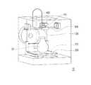
図1は、本発明の1つの実施形態に係る3Dプリンタに適用するプリントヘッドモジュールの概略図である。図1を参照すると、本実施形態のプリントヘッドモジュール100は、3Dプリンタ10に適用することができる。3Dプリンタ10は、例えば、デジタル3Dモデルに基づいて3D物体20を印刷するよう構成される。3Dプリンタ10は、本実施形態のプリントヘッドモジュール100と、ベース200と、スライドレール300とを含む。プリントヘッドモジュール100は、モデル材料を用いてベース200上に3D物体20を層毎に形成するよう構成される。図1に示したベース200は、搬送面210を有し、プリントヘッドモジュール100によって提供されたモデル材料を搬送する。モデル材料は、例えば、図1に示すように、熱溶融材料で構成された固体フィラメント400であってもよく、ノズル139に伝送される。スライドレール300は、ベース200の上方に配置される。本実施形態において、スライドレール300の延伸方向は、搬送面210に平行である。プリントヘッドモジュール100は、スライドレール300に沿って前後にスライドするよう構成され、ベース200は、例えば、プリントヘッドモジュール100に平行に、且つ相対して移動することができる。 FIG. 1 is a schematic view of a print head module applied to a 3D printer according to one embodiment of the present invention. Referring to FIG. 1, the
詳しく説明すると、3Dプリンタ10は、さらに、プリントヘッドモジュール100に結合され、デジタル3Dモデルを処理するよう構成された制御ユニットを含む。デジタル3Dモデルは、CAD(computer-aided design)、アニメーションモデリングソフトウェア等を用いてコンピュータホストで作成したデジタル3D画像ファイルであってもよい。制御ユニットは、デジタル3Dモデルに基づいて、スライドレール300に沿って移動するようプリントヘッドモジュール100を制御し、プリントヘッドモジュール100は、移動しながらモデル材料を搬送面210に層毎に分配して、3D物体20を形成する。 Specifically, the
図2は、本発明の1つの実施形態に係るプリントヘッドモジュールの側面図である。図3は、本発明の1つの実施形態に係るプリントヘッドモジュールの拡大図である。図2および図3を参照すると、本実施形態において、プリントヘッドモジュール100は、ブラケット110と、ロック機構120と、プリントヘッド130とを含む。ブラケット110は、収容溝112と、支持体111とを含み、ブラケット110は、図1に示すように、スライドレール300の上にスライド可能に配置される。本実施形態において、ブラケット110の底部は、スライドレール300を通すための複数のスルーホール114を含む。つまり、スライドレール300は、スルーホール114を通過するため、ブラケット110は、スライドレール300に沿って前後にスライドすることができる。本実施形態において、プリントヘッドモジュール100は、さらに、ブラケット110に結合されたモータ140を含み、スライドレール300に沿ってスライドするようブラケット110を駆動する。本実施形態において、3Dプリンタ10の制御ユニットは、デジタル3Dモデルに基づいてモータ140を制御し、スライドレール300に沿ってスライドするようブラケット110を駆動することにより、プリントヘッドモジュール100の全体の動きを制御する。 FIG. 2 is a side view of a printhead module according to one embodiment of the present invention. FIG. 3 is an enlarged view of a printhead module according to one embodiment of the present invention. 2 and 3, in the present embodiment, the
また、プリントヘッド130は、ロック機構120を介して収容溝112内に取り外し可能に配置される。ロック機構120は、ブラケット110の上に配置され、押圧部材122と、ロック部材124と、弾性部材126とを含む。押圧部材122は、支持体111に固定され、収容溝112の上方に設置される。本実施形態において、支持体111は、ロック孔111aと、固定部111bとを含む。押圧部材122は、押圧部材122が支持体111に固定されるよう、ロック孔111aを通過して、それと係合する第2フック122cを含む。ロック部材124は、押圧部材122に枢接され、回転方向R1に沿って押圧部材122に相対して回転する。詳しく説明すると、ロック部材124は、図3に示すように、ロック部材124が回転方向R1に沿って押圧部材122に相対して回転できるよう、さらに、押圧部材122の回転軸にスリーブ接続(sleeved on)された旋回素子124cを含む。弾性部材126は、押圧部材122とロック部材124の間にもたれかかる。プリントヘッド130は、収容溝112内に取り外し可能に配置される。 The
図4は、本発明の1つの実施形態に係るプリントヘッドモジュールの部分的拡大図である。図3および図4を参照しながら、詳細に説明すると、ロック部材124は、少なくとも1つの第1位置決め部124aと、第1材料入口122bとを有する。押圧部材122は、モデル材料が第1材料入口122bおよび第2材料入口124dを通過してプリントヘッド130に供給されるよう、第1材料入口122bに対応し、且つ連結した第2材料入口124dを有する。プリントヘッド130は、第1位置決め部124aに対応する少なくとも1つの第2位置決め部132と、プリントヘッド130の上面に設置された第3材料入口131とを含む。第3材料入口131は、モデル材料が材料入口122b、124dおよび131を順番に通過してプリントヘッド130にスムーズに供給されるよう、第1材料入口122bおよび第2材料入口124dに対応する。プリントヘッド130を収容溝122内に配置する時は、使用者がロック部材124を持ち上げることにより、ロック部材124を押圧部材122に向かって回転させることができる。この時、押圧部材122とロック部材124の間に配置された弾性部材126が押圧され、押圧部材122から離れようとする復元力F1がロック部材124に提供される。プリントヘッド130を収容溝122内に配置した後、使用者は、ロック部材124を解放することができる。この時、ロック部材124は、弾性部材126によって提供された復元力F1を負っているため、元の位置に戻る。これにより、ロック部材124の第1位置決め部124aがプリントヘッド130の第2位置決め部132と係合されて、プリントヘッド130をロック部材124とブラケット110の間に制限する。 FIG. 4 is a partially enlarged view of a printhead module according to one embodiment of the present invention. Describing in detail with reference to FIGS. 3 and 4, the locking
同様に、プリントヘッド130をブラケット110から取り外す時は、使用者が再度ロック部材124を持ち上げることにより、ロック部材124を押圧部材122に向かって回転させることができるため、第1位置決め部124aが第2位置決め部132から外れて、プリントヘッド130とブラケット110の間の構造的干渉を解放することができる。これにより、使用者は、プリントヘッド130をブラケット110から容易に取り外すことができる。 Similarly, when the
本実施形態において、第1位置決め部124aは、収容溝112に面する凸部であってもよい。第2位置決め部132は、プリントヘッド130の上面134に配置され、凸部と係合するのに適した凹部であってもよい。また、プリントヘッド130は、図4に示すように、さらに、ケース138を含む。第2位置決め部132および第3材料入口131は、ケース138の上面134に配置される。詳しく説明すると、押圧部材122は、さらに、少なくとも1つの位置決め孔122aを含む。ロック部材124は、さらに、少なくとも1つの第1フック124bを含む。第1フック124bは、押圧部材122とロック部材124が互いに接続されるよう、位置決め孔122aを通過し、且つ位置決め孔122aと構造的に干渉する。 In the present embodiment, the first positioning portion 124 a may be a convex portion facing the
上述した配置により、プリントヘッド130が収容溝122内に配置された時、ロック部材124の第1位置決め部124aがプリントヘッド130の第2位置決め部132と係合され、プリントヘッド130がブラケット110に固定される。プリントヘッド130をブラケット110から取り外す時は、使用者が押圧部材122に向かってロック部材124を持ち上げるだけで、第1位置決め部124aが第2位置決め部132から分離して、プリントヘッド130とブラケット110の間の構造的干渉が解放され、使用者は、プリントヘッド130をブラケット110から取り外すことができる。 With the arrangement described above, when the
図5は、本発明の1つの実施形態に係るプリントヘッドモジュールの部分的拡大図である。図6は、本発明の1つの実施形態に係るプリントヘッドモジュールの部分図である。図5および図6を参照すると、本実施形態において、プリントヘッド130は、さらに、ノズル139を含む。ブラケット110は、さらに、材料供給管116と、材料供給モジュール118とを含む。材料供給モジュール118は、材料供給管116とノズル139の間に設置され、モデル材料をノズル139に伝送する。材料供給管116は、支持体111の固定部111bに配置され、材料入口122b、124d、131およびノズル139に対応する。プリントヘッド130が収容溝112内に配置された時、ノズル139の位置が材料供給管116の位置と対応するため、モデル材料は、材料供給モジュール118により材料供給管116を通ってノズルに伝送される。また、プリントヘッドモジュール100は、さらに、加熱ユニット150を含んでもよい。モデル材料は、図6に示すように、固体フィラメント400の形状をした熱溶融材料であってもよい。モデル材料は、図3に示すように、材料供給管116を通ってノズル139に伝送される。加熱ユニット150は、ノズル139に伝送されたモデル材料を加熱するよう構成され、それにより、モデル材料を溶融状態の溶融モデル材料に変えて、プリントヘッド130から搬送面122に層毎に押し出し、図1に示すように、互いに積み重ねられた複数のモデル材料層で構成された3D物体20を形成する。本実施形態において、モデル材料は、例えば、ポリ乳酸(polylactic acid, PLA)、ABS樹脂(Acrylonitrile Butadiene Styrene)またはその他の熱溶融ポリマーであってもよい。 FIG. 5 is a partially enlarged view of a printhead module according to one embodiment of the present invention. FIG. 6 is a partial view of a printhead module according to one embodiment of the present invention. Referring to FIGS. 5 and 6, in this embodiment, the
本実施形態において、プリントヘッドモジュール100は、図3に示すように、さらに、プリントヘッド130の上に配置されたファン160を含む。ファン160の空気出口面は、材料供給管116に面し、空気出口面は、例えば、材料供給管116の縦方向に平行であってもよい。また、別の実施形態において、図2および図5に示すように、ファン160の空気出口面162と材料供給管116の縦方向A1の間が鋭角となるよう、プリントヘッドモジュール100は、図5に示すように、さらに、ファン160とプリントヘッド130の間にもたれかかる傾斜部材180を含む。これにより、ファン160によって提供された冷却空気がノズル139に向かって伝送され、ノズル139の温度が高くなりすぎてモデル材料が急に柔らかくなったり、溶けたりしないようにする。 In the present embodiment, the
また、プリントヘッド130は、さらに、ノズル139に結合された温度検知ユニット136を含み、ノズル139の温度を検知する。本実施形態において、3Dプリンタ10の制御ユニットは、温度検知ユニット136を介してノズル139の温度を取得し、それに基づいてノズル139の温度を特定範囲内に制御する。言及すべきこととして、ノズル139の温度は、モデル材料の融点よりも実質的に高くなるよう制御されるため、モデル材料は、溶けて溶融モデル材料になることができる。 In addition, the
図7は、本発明の1つの実施形態に係るプリントヘッドモジュールのファンおよび放熱ブロックの概略図である。図8は、本発明の1つの実施形態に係るプリントヘッドモジュールのプリントヘッドおよび放熱ブロックの概略図である。図7および図8を参照すると、本実施形態において、上述した配置の他に、プリントヘッドモジュール100は、さらに、放熱ブロック170を含み、材料供給管138の放熱をさらに行ってもよい。放熱ブロック170は、ファン160に接続されるため、ファン160によって提供された冷却空気が放熱ブロック170に伝送され、放熱ブロックの放熱を補助する。本実施形態において、ファン160は、図7に示すように、プリントヘッド130のケース138および放熱ブロック170と係合した複数のリベット(rivet)を有するため、プリントヘッド130、放熱ブロック170およびファン160の間の接続関係が固定される。 FIG. 7 is a schematic diagram of a fan and a heat dissipation block of a printhead module according to one embodiment of the present invention. FIG. 8 is a schematic view of a print head and a heat dissipation block of a print head module according to one embodiment of the present invention. 7 and 8, in the present embodiment, in addition to the arrangement described above, the
以上のように、本発明のプリントヘッドモジュールは、ブラケット上のロック機構とプリントヘッドの位置決め部の間の構造的係合を利用するため、プリントヘッドがブラケットの収容溝内に配置された時に、ロック機構がプリントヘッドの位置決め部と係合され、プリントヘッドをブラケットに固定し、且つそこから容易に取り外すことができる。それにより、本発明のプリントヘッドモジュールは、クリーニング、交換およびメンテナンス時に、プリントヘッドを取り外したり、組み立てたりすることができるため、プリントヘッドモジュールの使用およびメンテナンス上の便利性をさらに向上させることができる。 As described above, since the print head module of the present invention utilizes the structural engagement between the locking mechanism on the bracket and the positioning portion of the print head, when the print head is disposed in the receiving groove of the bracket, A locking mechanism is engaged with the printhead positioning to secure the printhead to the bracket and to be easily removed therefrom. As a result, the printhead module of the present invention can be removed and assembled at the time of cleaning, replacement and maintenance, so that the convenience of use and maintenance of the printhead module can be further improved. .
以上のごとく、この発明を実施形態により開示したが、もとより、この発明を限定するためのものではなく、当業者であれば容易に理解できるように、この発明の技術思想の範囲内において、適当な変更ならびに修正が当然なされうるものであるから、その特許権保護の範囲は、特許請求の範囲および、それと均等な領域を基準として定めなければならない。 As described above, the present invention has been disclosed by the embodiments. However, the present invention is not intended to limit the present invention, and is within the scope of the technical idea of the present invention so that those skilled in the art can easily understand. Therefore, the scope of patent protection should be defined based on the scope of claims and the equivalent area.
本発明のプリントヘッドモジュールは、クリーニング、交換およびメンテナンス時に、プリントヘッドを取り外したり、組み立てたりすることができるため、プリントヘッドモジュールの使用およびメンテナンス上の便利性をさらに向上させることができる。 Since the printhead module of the present invention can be removed and assembled during cleaning, replacement and maintenance, the convenience of use and maintenance of the printhead module can be further improved.
10 3Dプリンタ
20 3D物体
100 プリントヘッドモジュール
110 ブラケット
111 支持体
111a ロック孔
111b 固定部
112 収容溝
114 スルーホール
116 材料供給管
118 材料供給モジュール
120 ロック機構
122 押圧部材
122a 位置決め孔
122b 第1材料入口
122c 第2フック
124 ロック部材
124a 第1位置決め部
124b 第1フック
124c 旋回素子
124d 第2材料入口
126 弾性部材
130 プリントヘッド
131 第3材料入口
132 第2位置決め部
134 上面
136 温度検知ユニット
138 材料供給管
139 ノズル
140 モータ
150 加熱ユニット
160 ファン
162 空気出口面
170 放熱ブロック
200 ベース
210 搬送面
300 スライドレール
A1 縦方向
F1 復元力
R1 回転方向10
Claims (11)
Translated fromJapanese収容溝および支持体を含むブラケットと、
前記ブラケットの上に配置され、前記支持体に固定された押圧部材、前記押圧部材に枢接されたロック部材、および前記押圧部材と前記ロック部材の間にもたれかかる弾性部材を含み、前記ロック部材が、少なくとも1つの第1位置決め部および第1材料入口を有し、前記押圧部材が、前記第1材料入口に対応し、前記モデル材料を供給する第2材料入口を有するロック機構と、
前記収容溝内に取り外し可能に配置され、前記第1位置決め部と係合するよう構成された少なくとも1つの第2位置決め部を含み、前記弾性部材が押圧されると、前記押圧部材から離れようとする復元力が前記ロック部材に提供されて、前記ロック部材と前記ブラケットの間に制限されるプリントヘッドと
を含むプリントヘッドモジュール。A printhead module configured to form layer-by-layer 3D objects on a transport surface of a base using a model material,
A bracket including a receiving groove and a support;
A locking member disposed on the bracket and fixed to the support; a locking member pivotally connected to the pressing member; and an elastic member leaning between the pressing member and the locking member. A locking mechanism having at least one first positioning portion and a first material inlet, wherein the pressing member has a second material inlet corresponding to the first material inlet and supplying the model material;
It includes at least one second positioning portion that is detachably disposed in the receiving groove and is configured to engage with the first positioning portion, and when the elastic member is pressed, the pressing member is separated from the pressing member. A print head module comprising: a print head, wherein a restoring force is provided to the lock member to limit the lock member and the bracket.
前記プリントヘッドに結合されるとともに、前記ノズル内の前記モデル材料を加熱するよう構成され、前記モデル材料を溶かして溶融モデル材料にし、前記溶融モデル材料を前記ノズルから押し出す加熱ユニットを含む請求項4に記載のプリントヘッドモジュール。The model material is a hot-melt material, and the printhead module further includes:
5. A heating unit coupled to the print head and configured to heat the model material in the nozzle, melting the model material into a molten model material, and including a heating unit for extruding the molten model material from the nozzle. A printhead module according to claim 1.
Applications Claiming Priority (2)
| Application Number | Priority Date | Filing Date | Title |
|---|---|---|---|
| TW103100420ATWI486263B (en) | 2014-01-06 | 2014-01-06 | Printing head module |
| TW103100420 | 2014-01-06 |
Publications (2)
| Publication Number | Publication Date |
|---|---|
| JP2015128892Atrue JP2015128892A (en) | 2015-07-16 |
| JP5889966B2 JP5889966B2 (en) | 2016-03-22 |
Family
ID=53494530
Family Applications (1)
| Application Number | Title | Priority Date | Filing Date |
|---|---|---|---|
| JP2014137320AExpired - Fee RelatedJP5889966B2 (en) | 2014-01-06 | 2014-07-03 | Printhead module |
Country Status (4)
| Country | Link |
|---|---|
| US (1) | US9216545B2 (en) |
| JP (1) | JP5889966B2 (en) |
| CN (1) | CN104760278B (en) |
| TW (1) | TWI486263B (en) |
Cited By (6)
| Publication number | Priority date | Publication date | Assignee | Title |
|---|---|---|---|---|
| KR101798899B1 (en)* | 2016-09-07 | 2017-11-17 | 티에이치산업주식회사 | Nozzle fixing bracket of 3D-printer |
| KR101820823B1 (en)* | 2016-09-07 | 2018-01-22 | 티에이치산업주식회사 | Scrw fixture of 3D-printer |
| KR101867757B1 (en)* | 2017-02-20 | 2018-06-14 | 백철민 | Mmaterial supply nozzle device for 3D printer |
| JP2018535310A (en)* | 2015-09-16 | 2018-11-29 | アプライド マテリアルズ インコーポレイテッドApplied Materials,Incorporated | Printhead module for add-on manufacturing systems |
| JP2022522953A (en)* | 2019-01-09 | 2022-04-21 | アーエム デザイン エー.ウー. | Tool unit |
| KR102765627B1 (en)* | 2024-05-22 | 2025-02-12 | 주식회사 루고랩스 | Multi output head module for 3d printer |
Families Citing this family (16)
| Publication number | Priority date | Publication date | Assignee | Title |
|---|---|---|---|---|
| WO2016007672A1 (en) | 2014-07-09 | 2016-01-14 | Applied Materials, Inc. | Layerwise heating, linewise heating, plasma heating and multiple feed materials in additive manufacturing |
| KR102209307B1 (en)* | 2014-08-18 | 2021-01-28 | 엘지전자 주식회사 | 3D printer |
| US9878481B2 (en)* | 2015-03-02 | 2018-01-30 | Makerbot Industries, Llc | Extruder for three-dimensional printers |
| WO2017048865A1 (en) | 2015-09-16 | 2017-03-23 | Applied Materials, Inc. | Adjustable z-axis printhead module for additive manufacturing system |
| JP2018530672A (en)* | 2015-09-16 | 2018-10-18 | アプライド マテリアルズ インコーポレイテッドApplied Materials,Incorporated | Array of printhead modules for additive manufacturing systems |
| CN106903874B (en)* | 2015-12-19 | 2019-05-31 | 深圳市利宏伟实业有限公司 | 3D printer based on FDM technology |
| CN107627596B (en)* | 2016-07-14 | 2020-05-05 | 东友科技股份有限公司 | Extrusion device of three-dimensional printer, cooling mechanism and cooling method thereof |
| TW201801895A (en) | 2016-07-14 | 2018-01-16 | 東友科技股份有限公司 | Extrusion device of three-dimensional printer and cooling mechanism and cooling method thereof |
| CN109715368A (en) | 2016-10-19 | 2019-05-03 | 惠普发展公司,有限责任合伙企业 | Three-dimension object generates |
| JP6915298B2 (en)* | 2017-02-22 | 2021-08-04 | セイコーエプソン株式会社 | Liquid injection device and maintenance device |
| CN107379543B (en)* | 2017-05-31 | 2019-10-01 | 江苏齐龙电子科技有限公司 | A kind of 3D printer equipment |
| CN107379548B (en)* | 2017-05-31 | 2019-04-23 | 南京华塑增材制造有限公司 | A kind of 3D printer |
| CN107053659B (en)* | 2017-05-31 | 2018-06-15 | 江苏锡沂高新区科技发展有限公司 | A kind of 3D printer |
| WO2019078809A1 (en) | 2017-10-16 | 2019-04-25 | Hewlett-Packard Development Company, L.P. | Vents for fluid dispensing assemblies |
| JP7206799B2 (en)* | 2018-10-24 | 2023-01-18 | セイコーエプソン株式会社 | printer |
| WO2021216258A1 (en)* | 2020-04-22 | 2021-10-28 | Rowan University | Multi-material printer device for manufacture of high-throughput screening microfluidic chips |
Citations (4)
| Publication number | Priority date | Publication date | Assignee | Title |
|---|---|---|---|---|
| JP2000500709A (en)* | 1995-11-13 | 2000-01-25 | ストラタシス・インコーポレイテッド | Solid prototyping method and apparatus |
| JP2004504177A (en)* | 2000-07-13 | 2004-02-12 | ストラタシス・インコーポレイテッド | Filament cassette and loading system |
| JP2011511719A (en)* | 2008-01-08 | 2011-04-14 | ストラタシス,インコーポレイテッド | Consumable assemblies used in laminated deposition systems by extrusion |
| WO2012088253A1 (en)* | 2010-12-22 | 2012-06-28 | Stratasys, Inc. | Print head assembly for use in fused deposition modeling system |
Family Cites Families (17)
| Publication number | Priority date | Publication date | Assignee | Title |
|---|---|---|---|---|
| EP2292413B1 (en)* | 2003-05-01 | 2016-09-07 | Stratasys Ltd. | Rapid prototyping apparatus |
| US7399130B2 (en)* | 2004-03-03 | 2008-07-15 | Zih Corporation | Printer with quick release print head and platen to promote installation and removal of same |
| TWI233889B (en)* | 2004-06-02 | 2005-06-11 | Benq Corp | Ink cartridge positioning mechanism and method thereof |
| DE102004051231A1 (en)* | 2004-10-20 | 2006-05-04 | Dreve Otoplastik Gmbh | Method of making earmolds with heterogeneous material properties based on 3D printer technology |
| JP4505376B2 (en)* | 2005-03-30 | 2010-07-21 | 株式会社新盛インダストリーズ | Head attachment / detachment mechanism for thermal printer |
| JP2007320121A (en)* | 2006-05-31 | 2007-12-13 | Toshiba Tec Corp | Double-sided thermal printer and thermal head holding method |
| US8153182B2 (en)* | 2008-10-21 | 2012-04-10 | Stratasys, Inc. | Adjustable head mount for digital manufacturing system |
| CN101905567B (en)* | 2010-07-22 | 2012-01-18 | 北京美科艺数码科技发展有限公司 | Mounting adjustment mechanism of spraying head of ink-jet printer |
| EP2655046B1 (en) | 2010-12-22 | 2019-05-22 | Stratasys, Inc. | Print head assembly for use in fused deposition modeling system |
| US8663533B2 (en) | 2010-12-22 | 2014-03-04 | Stratasys, Inc. | Method of using print head assembly in fused deposition modeling system |
| US8465111B2 (en) | 2010-12-22 | 2013-06-18 | Stratasys, Inc. | Print head for use in fused deposition modeling system |
| US9238329B2 (en) | 2010-12-22 | 2016-01-19 | Stratasys, Inc. | Voice coil mechanism for use in additive manufacturing system |
| US8419996B2 (en) | 2010-12-22 | 2013-04-16 | Stratasys, Inc. | Print head assembly for use in fused deposition modeling system |
| CN103171151B (en)* | 2013-03-24 | 2015-12-09 | 广州市文搏智能科技有限公司 | A kind of 3D printing-forming method and 3D printing-forming device |
| CN103128972B (en)* | 2013-03-24 | 2015-07-01 | 张哲夫 | Assembly-free 3D (three dimensional) printing formation method and device |
| CN104608502B (en)* | 2013-11-05 | 2017-01-04 | 芯发威达电子(上海)有限公司 | Easily-detachable thermal printing printer |
| TW201522087A (en)* | 2013-12-12 | 2015-06-16 | 三緯國際立體列印科技股份有限公司 | Printing head module |
- 2014
- 2014-01-06TWTW103100420Apatent/TWI486263B/ennot_activeIP Right Cessation
- 2014-02-17CNCN201410052684.XApatent/CN104760278B/ennot_activeExpired - Fee Related
- 2014-03-26USUS14/225,456patent/US9216545B2/ennot_activeExpired - Fee Related
- 2014-07-03JPJP2014137320Apatent/JP5889966B2/ennot_activeExpired - Fee Related
Patent Citations (4)
| Publication number | Priority date | Publication date | Assignee | Title |
|---|---|---|---|---|
| JP2000500709A (en)* | 1995-11-13 | 2000-01-25 | ストラタシス・インコーポレイテッド | Solid prototyping method and apparatus |
| JP2004504177A (en)* | 2000-07-13 | 2004-02-12 | ストラタシス・インコーポレイテッド | Filament cassette and loading system |
| JP2011511719A (en)* | 2008-01-08 | 2011-04-14 | ストラタシス,インコーポレイテッド | Consumable assemblies used in laminated deposition systems by extrusion |
| WO2012088253A1 (en)* | 2010-12-22 | 2012-06-28 | Stratasys, Inc. | Print head assembly for use in fused deposition modeling system |
Cited By (8)
| Publication number | Priority date | Publication date | Assignee | Title |
|---|---|---|---|---|
| JP2018535310A (en)* | 2015-09-16 | 2018-11-29 | アプライド マテリアルズ インコーポレイテッドApplied Materials,Incorporated | Printhead module for add-on manufacturing systems |
| US10967626B2 (en) | 2015-09-16 | 2021-04-06 | Applied Materials, Inc. | Printhead module for additive manufacturing system |
| KR101798899B1 (en)* | 2016-09-07 | 2017-11-17 | 티에이치산업주식회사 | Nozzle fixing bracket of 3D-printer |
| KR101820823B1 (en)* | 2016-09-07 | 2018-01-22 | 티에이치산업주식회사 | Scrw fixture of 3D-printer |
| KR101867757B1 (en)* | 2017-02-20 | 2018-06-14 | 백철민 | Mmaterial supply nozzle device for 3D printer |
| JP2022522953A (en)* | 2019-01-09 | 2022-04-21 | アーエム デザイン エー.ウー. | Tool unit |
| JP7386872B2 (en) | 2019-01-09 | 2023-11-27 | アーエム デザイン エー.ウー. | tool unit |
| KR102765627B1 (en)* | 2024-05-22 | 2025-02-12 | 주식회사 루고랩스 | Multi output head module for 3d printer |
Also Published As
| Publication number | Publication date |
|---|---|
| JP5889966B2 (en) | 2016-03-22 |
| TW201527130A (en) | 2015-07-16 |
| US9216545B2 (en) | 2015-12-22 |
| CN104760278A (en) | 2015-07-08 |
| US20150190963A1 (en) | 2015-07-09 |
| CN104760278B (en) | 2017-04-12 |
| TWI486263B (en) | 2015-06-01 |
Similar Documents
| Publication | Publication Date | Title |
|---|---|---|
| JP5889966B2 (en) | Printhead module | |
| US20150165676A1 (en) | Printing head module | |
| Günaydın et al. | Common FDM 3D printing defects | |
| CN108367464B (en) | How to print on a 3D jet printer | |
| JP4794465B2 (en) | Modeling apparatus having a tray substrate | |
| CN113242786B (en) | Three-dimensional printing device System and method | |
| TWI626167B (en) | Rotational printing head module having muti-cartridge | |
| US20200070420A1 (en) | Methods and apparatuses for additively manufacturing rubber | |
| Nilsiam et al. | Slicer and process improvements for open-source GMAW-based metal 3-D printing | |
| TWI596002B (en) | Three dimensional printing apparatus | |
| TWI586519B (en) | Material level detecting mechanism of three-dimensional system | |
| US10406746B2 (en) | Heating head for three-dimensional printing pen | |
| EP3231581B1 (en) | Three dimensional printing apparatus and printing head module | |
| JP6804322B2 (en) | Methods and devices for modeling 3D cylindrical objects | |
| CN204997998U (en) | Multi-head 3D printer with automatic print head replacement | |
| JP2017094726A (en) | Systems and methods for realizing three-dimensional (3D) object, component and element manufacturing including displacement / vibration welding or heat staking lamination | |
| CN106853676B (en) | Laminating method for FDM-3D printed article with excessive top-cutting | |
| JP2015039883A (en) | Three-dimensional printer and three-dimensional preview and printing method thereby | |
| US20160107392A1 (en) | Three-dimensional (3-d) digital finishing architecture | |
| JP2018079679A (en) | Printing head module | |
| JP6688708B2 (en) | 3D object printer | |
| CN204749273U (en) | Three -dimensional printer platform and three -dimensional printer | |
| EP3507076B1 (en) | 3d printer integrated filament cutter | |
| CN104723565A (en) | Powder recycling device of colorful 3DP (three-dimensional printing) machine | |
| KR101662501B1 (en) | Three-dimensional printer |
Legal Events
| Date | Code | Title | Description |
|---|---|---|---|
| A131 | Notification of reasons for refusal | Free format text:JAPANESE INTERMEDIATE CODE: A131 Effective date:20150519 | |
| A521 | Request for written amendment filed | Free format text:JAPANESE INTERMEDIATE CODE: A523 Effective date:20150811 | |
| TRDD | Decision of grant or rejection written | ||
| A01 | Written decision to grant a patent or to grant a registration (utility model) | Free format text:JAPANESE INTERMEDIATE CODE: A01 Effective date:20160126 | |
| A61 | First payment of annual fees (during grant procedure) | Free format text:JAPANESE INTERMEDIATE CODE: A61 Effective date:20160217 | |
| R150 | Certificate of patent or registration of utility model | Ref document number:5889966 Country of ref document:JP Free format text:JAPANESE INTERMEDIATE CODE: R150 | |
| R250 | Receipt of annual fees | Free format text:JAPANESE INTERMEDIATE CODE: R250 | |
| R250 | Receipt of annual fees | Free format text:JAPANESE INTERMEDIATE CODE: R250 | |
| R250 | Receipt of annual fees | Free format text:JAPANESE INTERMEDIATE CODE: R250 | |
| LAPS | Cancellation because of no payment of annual fees |