JP2015125217A - Optical coupling mechanism and optical transceiver - Google Patents
Optical coupling mechanism and optical transceiverDownload PDFInfo
- Publication number
- JP2015125217A JP2015125217AJP2013268534AJP2013268534AJP2015125217AJP 2015125217 AJP2015125217 AJP 2015125217AJP 2013268534 AJP2013268534 AJP 2013268534AJP 2013268534 AJP2013268534 AJP 2013268534AJP 2015125217 AJP2015125217 AJP 2015125217A
- Authority
- JP
- Japan
- Prior art keywords
- flange
- optical
- ferrule
- optical coupling
- base
- Prior art date
- Legal status (The legal status is an assumption and is not a legal conclusion. Google has not performed a legal analysis and makes no representation as to the accuracy of the status listed.)
- Pending
Links
- 230000003287optical effectEffects0.000titleclaimsabstractdescription96
- 230000008878couplingEffects0.000titleclaimsabstractdescription39
- 238000010168coupling processMethods0.000titleclaimsabstractdescription39
- 238000005859coupling reactionMethods0.000titleclaimsabstractdescription39
- 239000013307optical fiberSubstances0.000claimsabstractdescription25
- 238000010586diagramMethods0.000abstractdescription5
- 230000002950deficientEffects0.000description4
- 230000000694effectsEffects0.000description4
- 238000000034methodMethods0.000description3
- 230000005540biological transmissionEffects0.000description2
- RYGMFSIKBFXOCR-UHFFFAOYSA-NCopperChemical compound[Cu]RYGMFSIKBFXOCR-UHFFFAOYSA-N0.000description1
- 230000004308accommodationEffects0.000description1
- 238000005452bendingMethods0.000description1
- 239000000470constituentSubstances0.000description1
- 229910052802copperInorganic materials0.000description1
- 239000010949copperSubstances0.000description1
- 238000003795desorptionMethods0.000description1
- 239000000835fiberSubstances0.000description1
- 238000007526fusion splicingMethods0.000description1
- 230000009191jumpingEffects0.000description1
- 239000002184metalSubstances0.000description1
- 229910052751metalInorganic materials0.000description1
- 239000011347resinSubstances0.000description1
- 229920005989resinPolymers0.000description1
Images


Classifications
- G—PHYSICS
- G02—OPTICS
- G02B—OPTICAL ELEMENTS, SYSTEMS OR APPARATUS
- G02B6/00—Light guides; Structural details of arrangements comprising light guides and other optical elements, e.g. couplings
- G02B6/24—Coupling light guides
- G02B6/36—Mechanical coupling means
- G02B6/38—Mechanical coupling means having fibre to fibre mating means
- G02B6/3807—Dismountable connectors, i.e. comprising plugs
- G02B6/389—Dismountable connectors, i.e. comprising plugs characterised by the method of fastening connecting plugs and sockets, e.g. screw- or nut-lock, snap-in, bayonet type
- G02B6/3893—Push-pull type, e.g. snap-in, push-on
- G—PHYSICS
- G02—OPTICS
- G02B—OPTICAL ELEMENTS, SYSTEMS OR APPARATUS
- G02B6/00—Light guides; Structural details of arrangements comprising light guides and other optical elements, e.g. couplings
- G02B6/24—Coupling light guides
- G02B6/42—Coupling light guides with opto-electronic elements
- G02B6/4292—Coupling light guides with opto-electronic elements the light guide being disconnectable from the opto-electronic element, e.g. mutually self aligning arrangements
- G—PHYSICS
- G02—OPTICS
- G02B—OPTICAL ELEMENTS, SYSTEMS OR APPARATUS
- G02B6/00—Light guides; Structural details of arrangements comprising light guides and other optical elements, e.g. couplings
- G02B6/24—Coupling light guides
- G02B6/36—Mechanical coupling means
- G02B6/38—Mechanical coupling means having fibre to fibre mating means
- G02B6/3807—Dismountable connectors, i.e. comprising plugs
- G02B6/381—Dismountable connectors, i.e. comprising plugs of the ferrule type, e.g. fibre ends embedded in ferrules, connecting a pair of fibres
- G02B6/3818—Dismountable connectors, i.e. comprising plugs of the ferrule type, e.g. fibre ends embedded in ferrules, connecting a pair of fibres of a low-reflection-loss type
- G02B6/3821—Dismountable connectors, i.e. comprising plugs of the ferrule type, e.g. fibre ends embedded in ferrules, connecting a pair of fibres of a low-reflection-loss type with axial spring biasing or loading means
- G—PHYSICS
- G02—OPTICS
- G02B—OPTICAL ELEMENTS, SYSTEMS OR APPARATUS
- G02B6/00—Light guides; Structural details of arrangements comprising light guides and other optical elements, e.g. couplings
- G02B6/24—Coupling light guides
- G02B6/36—Mechanical coupling means
- G02B6/38—Mechanical coupling means having fibre to fibre mating means
- G02B6/3807—Dismountable connectors, i.e. comprising plugs
- G02B6/381—Dismountable connectors, i.e. comprising plugs of the ferrule type, e.g. fibre ends embedded in ferrules, connecting a pair of fibres
- G02B6/3825—Dismountable connectors, i.e. comprising plugs of the ferrule type, e.g. fibre ends embedded in ferrules, connecting a pair of fibres with an intermediate part, e.g. adapter, receptacle, linking two plugs
Landscapes
- Physics & Mathematics (AREA)
- General Physics & Mathematics (AREA)
- Optics & Photonics (AREA)
- Mechanical Coupling Of Light Guides (AREA)
- Optical Couplings Of Light Guides (AREA)
Abstract
Translated fromJapaneseDescription
Translated fromJapanese本発明は、光トランシーバ等の機器内に布線される内部光ファイバ同士を接続する光結合機構及び該光結合機構を備える光トランシーバに関する。 The present invention relates to an optical coupling mechanism for connecting internal optical fibers arranged in a device such as an optical transceiver, and an optical transceiver including the optical coupling mechanism.
近年、光通信では大伝送容量を確保するために波長分割多重方式が採用されることがある。例えば、CFP、QSFP(Quadrature Small Form factor Pluggable)等の業界標準規格では、波長グリッドがCWDM(Coarse Wavelength Division Multiplexing)、LAN-WDM(Local Area Network WDM)に基づく四波の光信号を一本の光ファイバ上に波長多重化して送受する。この場合、光トランシーバ等の光機器の筐体内に波長分割多重化素子(Optical Multiplexer/Demultiplexer)を搭載し、この素子から分割数に応じた内部光ファイバが引き出され、これら内部光ファイバは半導体レーザ(LD)、フォトダイオード(PD)等の光デバイスに導かれる。 In recent years, wavelength division multiplexing may be employed in optical communications to ensure a large transmission capacity. For example, in industry standards such as CFP and QSFP (Quadrature Small Form Factor Pluggable), the wavelength grid is based on CWDM (Coarse Wavelength Division Multiplexing) and LAN-WDM (Local Area Network WDM). Wavelength multiplexed on an optical fiber for transmission / reception. In this case, a wavelength division multiplexing element (Optical Multiplexer / Demultiplexer) is mounted in the housing of an optical device such as an optical transceiver, and an internal optical fiber corresponding to the number of divisions is drawn from this element. (LD), photo diode (PD) and other optical devices.
ここで、波長分割多重化素子と光デバイスとを内部光ファイバによって固定形式(ピグテール形式)で接続したとする。この場合、例えば、一個の光デバイスが不良と判断されたり、継続使用により不良に至ったりしたときに、素子−光デバイス間はピグテール形式で接続されているので、不良の光デバイスのみを交換するわけにはいかず、上記素子と全ての光デバイスを交換しなければならず、甚だ不経済の極みとなる。不良の光デバイスから引きだされるピグデール光ファイバを切断し、光デバイスを交換した後、融着接続により内部光ファイバを接続する、という方法も知られているが、この方法のためには予め適当な長さの(十分な余長を有する)ピグテールファイバを用意しておかなければならず、筺体内が光ファイバだらけになる、という状況も生まれる。 Here, it is assumed that the wavelength division multiplexing element and the optical device are connected by an internal optical fiber in a fixed format (pigtail format). In this case, for example, when one optical device is determined to be defective or defective due to continuous use, the element-optical device is connected in a pigtail form, so that only the defective optical device is replaced. In other words, the above elements and all optical devices must be exchanged, which is extremely uneconomical. A method is known in which a pigdale optical fiber drawn from a defective optical device is cut, the optical device is replaced, and then an internal optical fiber is connected by fusion splicing. An appropriate length (having a sufficient extra length) of the pigtail fiber must be prepared, and the inside of the housing is full of optical fibers.
特許文献1の光コネクタは、4つの光デバイスを搭載する4連の光レセプタクルに取り付けたときに内部光ファイバと光デバイスが光結合するようになっている。また、特許文献2及び3には、特許文献1の光コネクタと同様に、光ファイバ端全体を覆うハウジングを有すると共に当該光コネクタの取り付け側への係止構造がハウジングに設けられた光コネクタが開示されている。 The optical connector disclosed in Patent Document 1 is configured such that an internal optical fiber and an optical device are optically coupled when attached to a quadruple optical receptacle on which four optical devices are mounted. In addition, in Patent Documents 2 and 3, similar to the optical connector of Patent Document 1, there is an optical connector having a housing that covers the entire end of the optical fiber and that has a locking structure on the mounting side of the optical connector. It is disclosed.
機器の筺体内に搭載される光コネクタは、通常の光コネクタと異なり、その耐湿性、強靱性、係合利便性は次善の要求となる。前二者の特性は機器の筺体そのもので補償される。また、係合利便性については、一度筺体内にセットされた後は係合/解除を繰り返すものではない。むしろ、構造の簡潔さが第一義に要請される。ただでさえ部品搭載空間の確保が困難な光トランシーバ等の小型機器のさらに狭い空間、例えば、内蔵する回路基板と筺体の間などに光コネクタを搭載することが要請される場合もある。ハウジングを有する光コネクタをそのような狭い空間に搭載するのは難しい。 Unlike ordinary optical connectors, optical connectors mounted in the housing of equipment have the next best requirements for their moisture resistance, toughness, and convenience of engagement. The characteristics of the former two are compensated by the housing itself. As for the convenience of engagement, the engagement / release is not repeated once it is set in the housing. Rather, structural simplicity is the primary requirement. In some cases, it is required to mount an optical connector in a narrower space of a small device such as an optical transceiver where it is difficult to secure a component mounting space, for example, between a built-in circuit board and a housing. It is difficult to mount an optical connector having a housing in such a narrow space.
本発明は、上述のごとき実情に鑑みてなされたもので、簡潔な構造を有する光コネクタを用い、狭い空間に搭載可能な光結合構造及び当該光結合構造を備える光トランシーバを提供することをその目的とする。 The present invention has been made in view of the above circumstances, and provides an optical coupling structure that can be mounted in a narrow space using an optical connector having a simple structure and an optical transceiver including the optical coupling structure. Objective.
本発明の光結合構造は、一方の光ファイバの先端に装着された第1のフェルールと、該第1のフェルールの根元に付属する第1のフランジと、を有する第1の光コネクタと、他方の光ファイバの先端に装着された第2のフェルールと、該第2のフェルールの根元に付属する第2のフランジと、を有する第2の光コネクタと、前記第1のフェルールと前記第2のフェルールとを調芯するスリーブとを備え、前記第1の光コネクタは、前記第1のフランジと前記第2のフランジとを挟みこむホルダを有する。 The optical coupling structure of the present invention includes a first optical connector having a first ferrule attached to the tip of one optical fiber, and a first flange attached to the base of the first ferrule, and the other A second ferrule attached to the tip of the optical fiber, a second flange attached to the base of the second ferrule, a second optical connector, the first ferrule, and the second ferrule A sleeve for aligning the ferrule, and the first optical connector includes a holder that sandwiches the first flange and the second flange.
本発明によれば、光結合構造を簡潔にすることができ、また、小型機器の狭い空間にも光結合構造を搭載することができる。 According to the present invention, the optical coupling structure can be simplified, and the optical coupling structure can be mounted in a narrow space of a small device.
以下、図面を参照しながら、本発明の光結合機構及び光トランシーバに係る好適な実施形態について説明する。なお、本発明はこれらの例示に限定されるものではなく、特許請求の範囲によって示され、特許請求の範囲と均等の意味及び範囲内で全ての変更が含まれることを意図する。また、以下の発明において、異なる図面においても同じ符号を付した構成は同様のものであるとして、その説明を省略する。 Hereinafter, preferred embodiments of the optical coupling mechanism and the optical transceiver of the present invention will be described with reference to the drawings. In addition, this invention is not limited to these illustrations, is shown by the claim, and intends that all the changes are included within the meaning and range equivalent to the claim. In the following inventions, the same reference numerals are used in different drawings, and the description thereof is omitted.
図1は、本発明の光結合機構を構成するコネクタを雄/雌で個別に描いた図である。下記説明でも明らかにされるように、図のコネクタ10、20を厳密には雄/雌に区別することはできない。両コネクタ10、20はいずれもフェルール11、21(図3参照)を有しており、これらフェルール11、21を割スリーブ30の両側から挿入してフェルール11、21間の光結合を実現するものである。厳密に言うならば、割スリーブ30が雌であり、フェルール11、21を有する部材が雄である。 FIG. 1 is a diagram in which the connectors constituting the optical coupling mechanism of the present invention are drawn separately for males and females. As will be apparent from the following description, the
しかし、以下の説明では、図1(B)のコネクタ20がポケット24aを有しており、該ポケット24aに、図1(A)のコネクタ10に取り付けられている割スリーブ30が収納される構造であるため、図1(A)のコネクタ10を雄コネクタ10、図1(B)のコネクタ20を雌コネクタ20とそれぞれ呼ぶこととする。なお、雄コネクタ10から割スリーブを取り外したものが本発明の「第1の光コネクタ」に相当し、雌コネクタ20が本発明の「第2の光コネクタ」に相当する。 However, in the following description, the
雄コネクタ10は、光ファイバF1の先端に装着されたフェルール11を有し、このフェルール11の根元側にフランジ12が付属している。また、雄コネクタ10は、フェルール11側を内側としたときにフランジ12の外側にコイルスプリング13を有し、さらに、側面視U字状に形成されU字の底部に相当する部分がコイルスプリング13の外側に取り付けられるホルダ14を有する。ホルダ14は、例えば、銅等を材料とする金属製であるが、樹脂製であってもよい。 The
雌コネクタ20は、光ファイバF1とは別の光ファイバF2の先端に装着されたフェルール21を有し、このフェルール21の根元側にフランジ22が付属している。フェルール11、21とフランジ12、22とでは求められる寸法精度が異なるのでこれらは別体で構成することが好ましい。 The
図2は、雄コネクタ10と雌コネクタ20とを係合させた状態を示す斜視図である。本光結合機構における雄コネクタ10と雌コネクタ20の係合は、基本的には割スリーブ30とフェルール11、21の嵌合力によりもたらされる。さらに、U字状のホルダ14によってフランジ12とフランジ22とを挟みこむことで上記係合を補助する形態となっている。本例では、ホルダ14でフランジ12、22を挟み込む際、ホルダ14とフランジ12との間にコイルスプリング13が介在しており、コイルスプリング13の応力により上記係合がさらに補助されるようになっている。なお、上述の挟み込んだ状態では、フェルール11とフェルール21とが挿入された割スリーブ30は露出している。 FIG. 2 is a perspective view showing a state in which the
図3は、雄コネクタ10の構成部材を説明するための斜視図で、図3(A)は雄コネクタ10を割スリーブ30とホルダ14の図示を省略して描いたものであり、図3(B)はホルダ14を単体で描いたものである。 FIG. 3 is a perspective view for explaining the constituent members of the
フランジ12は、図3(A)に示すように、二つの切り欠き12aを有する。図1(A)から明らかなように、この切り欠き12aに沿ってホルダ14がセットされる。この構造により、ホルダ14が光ファイバ軸を中心として回転するのを抑えることができる。 As shown in FIG. 3A, the
U字状のホルダ14は、図3(B)に示すように、U字の底部に相当する部分に、角型で平面形状のベース14aを有する。ベース14aの中央には光ファイバF1を挿通する開口14bが形成されている。 As shown in FIG. 3B, the U-shaped
また、角型のベース14aの対向する二辺からフェルール11の延在方向にアーム14cが延出している。アーム14c間の距離は、フランジ12の切り欠き12aの底面間の距離にほぼ等しい。また、アーム14cそれぞれの先端はもう一方のアーム14cの方向に折り曲げられてフック14dが形成されている。アーム14cの幅は、例えば、フェルール11の外径よりも大きく、割スリーブ30程度とすることができる An
ベース14aの上記二辺の残りの二辺には、アーム14cの延出方向に折り曲げられてタブ14eが形成されている。タブ14eは次の二つの効果をもたらす。
第1は、ベース14aとフランジ12との間の空間に装着されるコイルスプリング13の、同空間内への収納を確実にする、という効果である。コイルスプリング13の内径は光ファイバF1の外径よりも大きく設定されており、コイルスプリング13は光ファイバ軸を中心に、左右、上下に移動可能であり、大きくがたつく。タブ14eとアーム14cによりベース14aの周囲を囲むことで、コイルスプリング13のがたつきをベース14aの平面内に収めることが可能となる。 The first effect is to ensure that the
タブ14eの第2の効果は、ホルダ14の強度を確保できる点にある。雄コネクタ10が雌コネクタ20と係合した状態では、後述するように、コイルスプリング13はベース14aとフランジ12との間で圧縮された状態で保持される。すなわち、コイルスプリング13には、ベース14aをフランジ12とは反対の側に押し付ける応力が加わる。タブ14eを設けることにより、この応力に対する耐性を高めることができる。 The second effect of the
アーム14cのほぼ中央には、アーム14c間の距離を狭めるような形状の鞍部14fが形成されている。この鞍部14fがフランジ12の前方側(フェルール11側)にあるか、あるいは、後方側(コイルスプリング13側)にあるかによって、雄/雌コネクタの脱着/係合を調整する。すなわち、ホルダ14を光ファイバF1に対してスライドさせて鞍部14fをフランジ12の後方側にセットすることにより、フェルール11が剥き出しになりフェルール11への割スリーブ30の装着を容易にすると同時に、雌コネクタ20のフェルール21の割スリーブ30への挿入時にフェルール21の先端がアーム14cの先端のフック14dに触れて損傷することを防止する。また、雄/雌係合後に後述のようにアーム14cの先端のフック14dを雌コネクタ20のフランジ22に係合させると、これは同時に鞍部14fが雄コネクタ10のフランジ12の前方側に移動していることを意味する。 A
図1(B)に戻り、雌コネクタ20についてさらに説明する。雌コネクタ20は、光ファイバF1とは別の光ファイバF2の先端に装着されたフェルール21を有し、このフェルール21の根元側に、一対の切り込み22aを有するフランジ22が付属している。切り込み22a間の距離は、雄コネクタ10のホルダ14のアーム14c間の距離にほぼ等しく、雌コネクタ20の切り込み22aは雄コネクタ10の切り欠き12aと同等に機能する。 Returning to FIG. 1B, the
フランジ22のフェルール21側の付け根は斜面22bに加工されており、雄コネクタ10と雌コネクタ20とを係合させる際には、アーム14cの先端のフック14dがこの斜面22bを滑り上がることで係合が容易となっている。フランジ22のフェルール21側とは反対側には斜面は形成されておらず、係合後のアーム14cにフェルール21の光軸方向に動かすような力が働いてもアーム14cは容易には動かないようになっている。なお、加工上の関係でフランジ22のフェルール21側とは反対側の根元には曲面が形成されてしまうが、該曲面に上記斜面22bの効果はない。 The base of the
また、フランジ22を介してフェルール21とは反対側のボディ部23も、フランジ22の切り込み22aと連続する形態で切り込み23aを有する。切り込み23aの切り込み深さは切り込み22aより深くなっており、ホルダ14のフック14d先端がこの深くされた切り込み22a内に収まるようになっている。 Further, the
フェルール21の周囲には、フランジ22からフェルール21と同方向に延び出すリング状のカバー24が設けられている。カバー24とフェルール21の間にポケット24aが形成されている。このポケット24aに雄コネクタ10側から割スリーブ30の先端が収容される。カバー24はフェルール21の先端を保護する機能も果たす。ポケット24aの径方向の幅は割スリーブ30の厚みよりも広くなっている。言い換えると、カバー24の内径は割スリーブ30の外径よりも大きく設定されている。 Around the
図4は、雄コネクタ10と雌コネクタ20とを係合させた状態を示す断面図である。上記係合時は図示するようにホルダ14のアーム14cの先端のフック14dが雌コネクタ20のボディ部23に形成された切り込み23aにセットされる。また、両フランジ12、22の切り込み12a、22aの位置は、ホルダ14のアーム14cにより整合されている(図2参照)。雄コネクタ10のコイルスプリング13は、フランジ12とホルダ14のベース14aとの間に圧縮された状態でセットされており、ベース14aを後方に押し付ける応力を付与している。この応力は、ホルダ14のフック14dと雌コネクタ20のフランジ22との係合を確実なものとする。上記係合時は、アーム14cの鞍部14fが両フランジ12、22間のほぼ中央に位置する。 FIG. 4 is a cross-sectional view showing a state where the
また、上述の係合時において、両方のフェルール11、21は、割スリーブ30内に挿入され、その先端同士が物理接触(Physical Contact)することで光結合が実現する。割スリーブ30の先端は雌コネクタ20のポケット24aの奥端からは離れている。ホルダ14のアーム14cの先端のフック14dが雌コネクタ20のフランジ22を超えてボディ部23に形成された切り込み23aに収納されフランジ22と係合される。それに加えて、ホルダ14のベース14aと雌コネクタ20のフランジ22との間に位置するコイルスプリング13が、フランジ12を雌コネクタ20側に押し付けると共に、ベース14a及びフック14dを介してフランジ22を雄コネクタ10側に押し付けている。これによりフェルール11、21同士の物理接触が安定する。 Moreover, at the time of the above-mentioned engagement, both the
図5は、雄コネクタ10と雌コネクタ20との係合手順を示す図である。係合の際は、まず、雌コネクタ20のホルダ14を後方側一杯に位置させ、ほぼ剥き出しになった雄コネクタ10のフェルール11へ、割スリーブ30を装着し、まず、図5(A)の状態にする。この時、アーム14cの鞍部14fはフランジ12の後方側に位置するので、鞍部14fがストッパとなって、アーム14cすなわちホルダ14が前方側にスライドすることを抑制する。 FIG. 5 is a diagram showing an engagement procedure between the
次いで、雄コネクタ10側の割スリーブ30を雌コネクタ20のポケット24aに挿入して図5(B)の状態にし、フェルール11、21を突き合わせる。そして、図5(C)に示すように、ホルダ14の鞍部14fが雄コネクタ10のフランジ12を乗り越えるように、ホルダ14を雌コネクタ20側にスライドさせ、その先端のフック14dを雌コネクタ20のボディ部23の切り込み23aにセットし、フック14dをフランジ22と係合させる。ホルダ14のスライド中に、コイルスプリング13の両端がフランジ12とホルダ14のベース14aに突き当たり、両者の間隔が狭くなり、コイルスプリング13が自然長よりも短くなる。この自然長よりも短くなったコイルスプリング13がホルダ14のベース14aを後方側に押し付け、結果、フック14dと雌コネクタ20すなわちフランジ22との係合力が生ずる。 Next, the
雄コネクタ10と雌コネクタ20との係合は、ホルダ14のアーム14cの鞍部14f付近を割スリーブ30側に押し込み、雌コネクタ20のフランジ22からアーム14cのフック14dを外すことで解除できる。 The engagement between the
以上の構成において、割スリーブ30の全長は、係合時の両フランジ12、22の間隔よりも短く設定されている。すなわち、割スリーブ30の先端は雌コネクタ20のポケット24aの底面に接触しない、または、割スリーブ30の他端は雄コネクタ10のフランジ12に接触しない、という状況が確実に作り出されるようになっている。これは、両フェルール11、21の先端の物理接触を確実にするためである。 In the above configuration, the overall length of the
本光結合機構は、光軸方向の保持力を高めるための構成を有するが、光軸に垂直な方向については同様な部材を有していない。光軸に垂直な方向の保持力は、割スリーブ30のフェルール11、21の保持力のみで維持している。通常は、当該方向の保持力は光コネクタのハウジングにより発揮される。しかし、本光結合機構は、光コネクタにハウジングを設けないことを特徴としている。これは、本光結合機構が、狭い筐体内での使用を前提としているためである。本光結合機構は、係合/脱着を頻繁に繰り返すことがない用途に好適に用いられる。 The optical coupling mechanism has a configuration for increasing the holding force in the optical axis direction, but does not have a similar member in the direction perpendicular to the optical axis. The holding force in the direction perpendicular to the optical axis is maintained only by the holding force of the
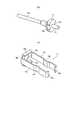
図6は、雄コネクタ10と雌コネクタ20とからなる光結合機構が用いられる光トランシーバの一例を示す図である。図の光トランシーバ50は、上筐体61と下筐体62からなる筐体60内に、雄コネクタ10と雌コネクタ20とからなる光結合機構を収納している。より詳細には、筐体60内の回路基板と下筐体62との間に上記光結合機構を収納している。 FIG. 6 is a diagram illustrating an example of an optical transceiver in which an optical coupling mechanism including the
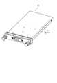
図7は、上記光結合機構の下筐体62への収納形態の一例を示す図である。図7(A)に示すように、下筐体62は、側壁62aで囲まれ周囲に対して窪んだ凹部62bを有する。凹部62bには、幅狭部位すなわちチャネル62cが形成されており、チャネル62cの一端の両側にガイド部62dが形成されている。また、下筐体62は後述のラグ板をネジ止めするためのネジ穴62eを有する。 FIG. 7 is a diagram illustrating an example of a storage form in the
上述の下筐体62に対し、図7(B)に示すように、割スリーブ30がチャネル62c内に位置すると共に一方のフランジ(図では雄コネクタ10のフランジ12)がガイド部62d内に位置するように、係合した状態の光結合機構を凹部62bにセットする。チャネル62cの長さはフランジ12、22間の距離と等しく、また、チャネル62cの幅は雌コネクタ20のカバー24の外径にほぼ等しい。このような寸法を有するチャネル62cに収納された光結合機構は、ガタつきなく該チャネル62cにセットされる。 As shown in FIG. 7B, the
その後、チャネル62cを覆うように図7(C)のラグ板70を被せ、ネジ穴62eに通したネジ71でラグ板70を固定することで、係合した光結合機構が下筺体62の内面に装着される。 Thereafter, the
ここで、ラグ板70は、上方に突出する凸部70aを中央部に有し、凸部70aの幅がホルダ14のアーム14cの幅にほぼ等しくなっている。これにより、アーム14cの跳ね上がりが適切に防止され、アーム14cと雌コネクタ20の係合が外れることがない。さらに、凸部70a内には下方に凸の別の部材(不図示)が組み合わされ、該別の部材がアーム14cの鞍部14fに挿入されるようになっている。上記別の部材の凸部の光軸方向の長さがアーム14cの鞍部14fの光軸方向の長さにほぼ等しくなっており、上記別の部材がアーム14cの鞍部14fと係合するので、アーム14cの光軸方向/前後方向のスライドが確実に防止される。 Here, the
なお、ガイド部62dはチャネル62cの両端に設け、両方のフランジ12、22を収納するようにしてもよい。 The
10…雄コネクタ、11…フェルール、12…フランジ、13…コイルスプリング、14…ホルダ、14a…ベース、14b…開口、14c…アーム、14d…フック、14e…タブ、14f…鞍部、20…雌コネクタ、21…フェルール、22…フランジ、23…ボディ部、24…カバー、24a…ポケット、30…割スリーブ、50…光トランシーバ、60…筐体、61…上筐体、62…下筐体、62a…側壁、62b…凹部、62c…チャネル、62d…ガイド部、62e…ネジ穴、70…ラグ板、70a…凸部、71…ネジ。DESCRIPTION OF
Claims (7)
Translated fromJapanese他方の光ファイバの先端に装着された第2のフェルールと、該第2のフェルールの根元に付属する第2のフランジと、を有する第2の光コネクタと、
前記第1のフェルールと前記第2のフェルールとを調芯するスリーブとを備え、
前記第1の光コネクタは、前記第1のフランジと前記第2のフランジとを挟みこむホルダを有する、光結合構造。A first optical connector having a first ferrule attached to the tip of one of the optical fibers and a first flange attached to the base of the first ferrule;
A second optical connector having a second ferrule attached to the tip of the other optical fiber, and a second flange attached to the base of the second ferrule;
A sleeve for aligning the first ferrule and the second ferrule;
The first optical connector has an optical coupling structure having a holder that sandwiches the first flange and the second flange.
該筺体は、前記光結合機構を収納する凹部と、該凹部から前記光結合機構が取り外れるのを防止する保持板を有し、該保持板の幅は前記光結合機構の前記第1のフランジと前記第2のフランジと間隔に相当する、光トランシーバ。The optical coupling structure according to any one of claims 1 to 6 is provided in a housing,
The housing includes a recess that houses the optical coupling mechanism, and a holding plate that prevents the optical coupling mechanism from being removed from the concave portion, and the width of the holding plate is the first flange of the optical coupling mechanism. And an optical transceiver corresponding to the distance between the second flange and the second flange.
Priority Applications (3)
| Application Number | Priority Date | Filing Date | Title |
|---|---|---|---|
| JP2013268534AJP2015125217A (en) | 2013-12-26 | 2013-12-26 | Optical coupling mechanism and optical transceiver |
| US14/579,781US9213150B2 (en) | 2013-12-26 | 2014-12-22 | Optical coupling apparatus and optical transceiver installing the same |
| CN201410834323.0ACN104749717B (en) | 2013-12-26 | 2014-12-26 | Optical couping device and the optical transceiver being provided with optical couping device |
Applications Claiming Priority (1)
| Application Number | Priority Date | Filing Date | Title |
|---|---|---|---|
| JP2013268534AJP2015125217A (en) | 2013-12-26 | 2013-12-26 | Optical coupling mechanism and optical transceiver |
Publications (1)
| Publication Number | Publication Date |
|---|---|
| JP2015125217Atrue JP2015125217A (en) | 2015-07-06 |
Family
ID=53481463
Family Applications (1)
| Application Number | Title | Priority Date | Filing Date |
|---|---|---|---|
| JP2013268534APendingJP2015125217A (en) | 2013-12-26 | 2013-12-26 | Optical coupling mechanism and optical transceiver |
Country Status (3)
| Country | Link |
|---|---|
| US (1) | US9213150B2 (en) |
| JP (1) | JP2015125217A (en) |
| CN (1) | CN104749717B (en) |
Cited By (18)
| Publication number | Priority date | Publication date | Assignee | Title |
|---|---|---|---|---|
| KR101930078B1 (en)* | 2017-09-14 | 2018-12-17 | 주식회사 디투에스 | A Fixing Clip For Optical fiber composite cable Connector |
| JP2019120936A (en)* | 2017-12-27 | 2019-07-22 | 日亜化学工業株式会社 | Fastening member and optical receptacle module |
| US10359577B2 (en) | 2017-06-28 | 2019-07-23 | Corning Research & Development Corporation | Multiports and optical connectors with rotationally discrete locking and keying features |
| US10379298B2 (en) | 2017-06-28 | 2019-08-13 | Corning Research & Development Corporation | Fiber optic connectors and multiport assemblies including retention features |
| JP2021092620A (en)* | 2019-12-09 | 2021-06-17 | 矢崎総業株式会社 | Optical connector |
| JP2021107884A (en)* | 2019-12-27 | 2021-07-29 | 住友電気工業株式会社 | Manufacturing method of optical component and press jig |
| US11294133B2 (en) | 2019-07-31 | 2022-04-05 | Corning Research & Development Corporation | Fiber optic networks using multiports and cable assemblies with cable-to-connector orientation |
| US11536921B2 (en) | 2020-02-11 | 2022-12-27 | Corning Research & Development Corporation | Fiber optic terminals having one or more loopback assemblies |
| US11604320B2 (en) | 2020-09-30 | 2023-03-14 | Corning Research & Development Corporation | Connector assemblies for telecommunication enclosures |
| WO2023100409A1 (en)* | 2021-12-01 | 2023-06-08 | 株式会社フジクラ | Optical connection structure |
| US11686913B2 (en) | 2020-11-30 | 2023-06-27 | Corning Research & Development Corporation | Fiber optic cable assemblies and connector assemblies having a crimp ring and crimp body and methods of fabricating the same |
| US11880076B2 (en) | 2020-11-30 | 2024-01-23 | Corning Research & Development Corporation | Fiber optic adapter assemblies including a conversion housing and a release housing |
| US11927810B2 (en) | 2020-11-30 | 2024-03-12 | Corning Research & Development Corporation | Fiber optic adapter assemblies including a conversion housing and a release member |
| US11994722B2 (en) | 2020-11-30 | 2024-05-28 | Corning Research & Development Corporation | Fiber optic adapter assemblies including an adapter housing and a locking housing |
| US12019279B2 (en) | 2019-05-31 | 2024-06-25 | Corning Research & Development Corporation | Multiports and other devices having optical connection ports with sliding actuators and methods of making the same |
| US12044894B2 (en) | 2018-12-28 | 2024-07-23 | Corning Research & Development Corporation | Multiport assemblies including mounting features or dust plugs |
| US12271040B2 (en) | 2017-06-28 | 2025-04-08 | Corning Research & Development Corporation | Fiber optic extender ports, assemblies and methods of making the same |
| US12372727B2 (en) | 2020-10-30 | 2025-07-29 | Corning Research & Development Corporation | Female fiber optic connectors having a rocker latch arm and methods of making the same |
Families Citing this family (23)
| Publication number | Priority date | Publication date | Assignee | Title |
|---|---|---|---|---|
| JP6498903B2 (en)* | 2014-09-30 | 2019-04-10 | 富士通コンポーネント株式会社 | Clip for ferrule, optical module and optical connector |
| US9720188B2 (en) | 2015-12-31 | 2017-08-01 | International Business Machines Corporation | Connecting mid-board optical modules |
| JP2018081144A (en)* | 2016-11-14 | 2018-05-24 | 住友電気工業株式会社 | Optical connector |
| US11668890B2 (en) | 2017-06-28 | 2023-06-06 | Corning Research & Development Corporation | Multiports and other devices having optical connection ports with securing features and methods of making the same |
| US11187859B2 (en) | 2017-06-28 | 2021-11-30 | Corning Research & Development Corporation | Fiber optic connectors and methods of making the same |
| US11300746B2 (en) | 2017-06-28 | 2022-04-12 | Corning Research & Development Corporation | Fiber optic port module inserts, assemblies and methods of making the same |
| US10281669B2 (en)* | 2017-07-14 | 2019-05-07 | Senko Advance Components, Inc. | Ultra-small form factor optical connectors |
| JP2019028214A (en)* | 2017-07-28 | 2019-02-21 | 住友電気工業株式会社 | Optical fiber coupler, optical device, optical transmitter, optical receiver, optical transmitter/receiver, and method of joining optical fibers |
| US10168488B1 (en)* | 2017-08-30 | 2019-01-01 | Te Connectivity Corporation | Tool-less ferrule retainer |
| CN108037566B (en)* | 2017-11-29 | 2023-07-25 | 国网河南省电力公司焦作供电公司 | A conveniently pluggable FC-type optical fiber connector and its operation method |
| US11221449B2 (en)* | 2018-05-11 | 2022-01-11 | Sumitomo Electric Industries, Ltd. | Optical connector, optical module and clip member |
| US10641967B1 (en) | 2018-11-16 | 2020-05-05 | Corning Research & Development Corporation | Multiport assemblies including a modular adapter support array |
| US10768382B2 (en) | 2018-11-29 | 2020-09-08 | Corning Research & Development Corporation | Multiport assemblies including access apertures and a release tool |
| JP7279424B2 (en)* | 2019-03-11 | 2023-05-23 | 住友電気工業株式会社 | optical transceiver |
| CN110196470B (en)* | 2019-04-29 | 2021-04-16 | 宁波天韵通信设备有限公司 | Optical fiber core insert ceramic sleeve |
| US11487073B2 (en) | 2019-09-30 | 2022-11-01 | Corning Research & Development Corporation | Cable input devices having an integrated locking feature and assemblies using the cable input devices |
| EP3805827B1 (en) | 2019-10-07 | 2025-07-30 | Corning Research & Development Corporation | Fiber optic terminals and fiber optic networks having variable ratio couplers |
| US11650388B2 (en) | 2019-11-14 | 2023-05-16 | Corning Research & Development Corporation | Fiber optic networks having a self-supporting optical terminal and methods of installing the optical terminal |
| TWI722902B (en)* | 2020-02-26 | 2021-03-21 | 立佳興業股份有限公司 | Latching structure and optical connector receptacle using the same |
| US11947167B2 (en) | 2021-05-26 | 2024-04-02 | Corning Research & Development Corporation | Fiber optic terminals and tools and methods for adjusting a split ratio of a fiber optic terminal |
| USD1036389S1 (en) | 2022-02-24 | 2024-07-23 | Sumitomo Electric Industries, Ltd. | Optical fiber connector |
| US12386124B2 (en)* | 2022-11-30 | 2025-08-12 | Mellanox Technologies, Ltd. | Device for holding a plurality of ferrules against a respective plurality of receptacles |
| CN116540365B (en)* | 2023-05-16 | 2024-04-26 | 安徽鹏大光电科技有限公司 | Optical fiber coupling connector assembly and connecting method |
Family Cites Families (12)
| Publication number | Priority date | Publication date | Assignee | Title |
|---|---|---|---|---|
| US5082345A (en)* | 1990-08-13 | 1992-01-21 | At&T Bell Laboratories | Optical fiber connecting device including attenuator |
| JP2780640B2 (en) | 1994-05-25 | 1998-07-30 | 住友電装株式会社 | Optical fiber cable connector |
| US5953475A (en) | 1995-09-01 | 1999-09-14 | Siemens Aktiengesellschaft | Fiber optic plug connector |
| DE19533498C2 (en) | 1995-09-01 | 1997-12-04 | Siemens Ag | Connector for an optical fiber cable |
| US5943461A (en)* | 1997-05-12 | 1999-08-24 | Lucent Technologies Inc | Connectorized optical module package and method using same with internal fiber connections |
| DE19809806A1 (en)* | 1998-03-09 | 1999-09-16 | Kromberg & Schubert | Contact arrangement for optical conductor, esp. for motor vehicles |
| JP2000180669A (en)* | 1998-12-17 | 2000-06-30 | Oki Electric Ind Co Ltd | Optical connector plug |
| DE502004009448D1 (en)* | 2004-02-19 | 2009-06-18 | Reichle & De Massari Fa | Connector housing of an optical connector for the industrial environment |
| JP2008091777A (en)* | 2006-10-04 | 2008-04-17 | Sumitomo Electric Ind Ltd | Optical transceiver |
| US7918611B2 (en)* | 2007-07-11 | 2011-04-05 | Emcore Corporation | Reconfiguration and protocol adaptation of optoelectronic modules and network components |
| WO2011052802A2 (en)* | 2009-10-29 | 2011-05-05 | Sumitomo Electric Industries, Ltd. | Pluggable optical transceiver and method for manufacturing the same |
| CN102455468B (en)* | 2010-10-19 | 2015-02-25 | 富士康(昆山)电脑接插件有限公司 | Optical fiber connector and optical fiber connector component |
- 2013
- 2013-12-26JPJP2013268534Apatent/JP2015125217A/enactivePending
- 2014
- 2014-12-22USUS14/579,781patent/US9213150B2/enactiveActive
- 2014-12-26CNCN201410834323.0Apatent/CN104749717B/enactiveActive
Cited By (51)
| Publication number | Priority date | Publication date | Assignee | Title |
|---|---|---|---|---|
| US11886017B2 (en) | 2017-06-28 | 2024-01-30 | Corning Research & Development Corporation | Multiports and other devices having connection ports with securing features and methods of making the same |
| US12271040B2 (en) | 2017-06-28 | 2025-04-08 | Corning Research & Development Corporation | Fiber optic extender ports, assemblies and methods of making the same |
| US10359577B2 (en) | 2017-06-28 | 2019-07-23 | Corning Research & Development Corporation | Multiports and optical connectors with rotationally discrete locking and keying features |
| US10379298B2 (en) | 2017-06-28 | 2019-08-13 | Corning Research & Development Corporation | Fiber optic connectors and multiport assemblies including retention features |
| US10386584B2 (en) | 2017-06-28 | 2019-08-20 | Corning Research & Development Corporation | Optical connectors with locking and keying features for interfacing with multiports |
| US10429593B2 (en) | 2017-06-28 | 2019-10-01 | Corning Research & Development Corporation | Fiber optic connectors and connectorization employing adapter extensions and/or flexures |
| US10429594B2 (en) | 2017-06-28 | 2019-10-01 | Corning Research & Development Corporation | Multiport assemblies including retention features |
| US10605998B2 (en) | 2017-06-28 | 2020-03-31 | Corning Research & Development Corporation | Fiber optic connectors and connectorization employing adhesive admitting adapters |
| US10802228B2 (en) | 2017-06-28 | 2020-10-13 | Corning Research & Development Corporation | Fiber optic connectors and multiport assemblies including retention features |
| US10809463B2 (en) | 2017-06-28 | 2020-10-20 | Corning Research & Development Corporation | Multiports and optical connectors with rotationally discrete locking and keying features |
| US12429655B2 (en) | 2017-06-28 | 2025-09-30 | Corning Optical Communications LLC | Multiports having connection ports with associated securing features and methods of making the same |
| US12379551B2 (en) | 2017-06-28 | 2025-08-05 | Corning Optical Communications LLC | Multiports having connection ports formed in the shell and associated securing features |
| US11215768B2 (en) | 2017-06-28 | 2022-01-04 | Corning Research & Development Corporation | Fiber optic connectors and connectorization employing adhesive admitting adapters |
| US12013578B2 (en) | 2017-06-28 | 2024-06-18 | Corning Research & Development Corporation | Multifiber fiber optic connectors, cable assemblies and methods of making the same |
| US11460646B2 (en) | 2017-06-28 | 2022-10-04 | Corning Research & Development Corporation | Fiber optic connectors and multiport assemblies including retention features |
| US12379552B2 (en) | 2017-06-28 | 2025-08-05 | Corning Research & Development Corporation | Compact fiber optic connectors, cable assemblies and methods of making the same |
| US11543600B2 (en) | 2017-06-28 | 2023-01-03 | Corning Research & Development Corporation | Compact fiber optic connectors having multiple connector footprints, along with cable assemblies and methods of making the same |
| US11966089B2 (en) | 2017-06-28 | 2024-04-23 | Corning Optical Communications, Llc | Multiports having connection ports formed in the shell and associated securing features |
| US11906792B2 (en) | 2017-06-28 | 2024-02-20 | Corning Research & Development Corporation | Compact fiber optic connectors having multiple connector footprints, along with cable assemblies and methods of making the same |
| US11579377B2 (en) | 2017-06-28 | 2023-02-14 | Corning Research & Development Corporation | Compact fiber optic connectors, cable assemblies and methods of making the same with alignment elements |
| US12353025B2 (en) | 2017-06-28 | 2025-07-08 | Corning Optical Communications LLC | Multiports having a connection port insert and methods of making the same |
| US12353024B2 (en) | 2017-06-28 | 2025-07-08 | Corning Research & Development Corporation | Multiports and optical connectors with rotationally discrete locking and keying features |
| US12298568B2 (en) | 2017-06-28 | 2025-05-13 | Corning Research & Development Corporation | Fiber optic connectors and multiport assemblies including retention features |
| US12276846B2 (en) | 2017-06-28 | 2025-04-15 | Corning Research & Development Corporation | Compact fiber optic connectors, cable assemblies and methods of making the same |
| US11703646B2 (en) | 2017-06-28 | 2023-07-18 | Corning Research & Development Corporation | Multiports and optical connectors with rotationally discrete locking and keying features |
| US11536913B2 (en) | 2017-06-28 | 2022-12-27 | Corning Research & Development Corporation | Fiber optic connectors and connectorization employing adhesive admitting adapters |
| US12174432B2 (en) | 2017-06-28 | 2024-12-24 | Corning Research & Development Corporation | Fiber optic connectors and connectorization employing adhesive admitting adapters |
| US11940656B2 (en) | 2017-06-28 | 2024-03-26 | Corning Research & Development Corporation | Compact fiber optic connectors, cable assemblies and methods of making the same |
| US12092878B2 (en) | 2017-06-28 | 2024-09-17 | Corning Research & Development Corporation | Fiber optic connectors having a keying structure and methods of making the same |
| US11914197B2 (en) | 2017-06-28 | 2024-02-27 | Corning Research & Development Corporation | Compact fiber optic connectors having multiple connector footprints, along with cable assemblies and methods of making the same |
| US11914198B2 (en) | 2017-06-28 | 2024-02-27 | Corning Research & Development Corporation | Compact fiber optic connectors having multiple connector footprints, along with cable assemblies and methods of making the same |
| KR101930078B1 (en)* | 2017-09-14 | 2018-12-17 | 주식회사 디투에스 | A Fixing Clip For Optical fiber composite cable Connector |
| JP7206484B2 (en) | 2017-12-27 | 2023-01-18 | 日亜化学工業株式会社 | Fastening member and optical receptacle module |
| JP2019120936A (en)* | 2017-12-27 | 2019-07-22 | 日亜化学工業株式会社 | Fastening member and optical receptacle module |
| US12044894B2 (en) | 2018-12-28 | 2024-07-23 | Corning Research & Development Corporation | Multiport assemblies including mounting features or dust plugs |
| US12019279B2 (en) | 2019-05-31 | 2024-06-25 | Corning Research & Development Corporation | Multiports and other devices having optical connection ports with sliding actuators and methods of making the same |
| US11294133B2 (en) | 2019-07-31 | 2022-04-05 | Corning Research & Development Corporation | Fiber optic networks using multiports and cable assemblies with cable-to-connector orientation |
| JP2021092620A (en)* | 2019-12-09 | 2021-06-17 | 矢崎総業株式会社 | Optical connector |
| JP7339144B2 (en) | 2019-12-09 | 2023-09-05 | 矢崎総業株式会社 | optical connector |
| JP2021107884A (en)* | 2019-12-27 | 2021-07-29 | 住友電気工業株式会社 | Manufacturing method of optical component and press jig |
| JP7306262B2 (en) | 2019-12-27 | 2023-07-11 | 住友電気工業株式会社 | Optical component manufacturing method and holding jig |
| US11536921B2 (en) | 2020-02-11 | 2022-12-27 | Corning Research & Development Corporation | Fiber optic terminals having one or more loopback assemblies |
| US11604320B2 (en) | 2020-09-30 | 2023-03-14 | Corning Research & Development Corporation | Connector assemblies for telecommunication enclosures |
| US12019285B2 (en) | 2020-09-30 | 2024-06-25 | Corning Research & Development Corporation | Connector assemblies for telecommunication enclosures |
| US12372727B2 (en) | 2020-10-30 | 2025-07-29 | Corning Research & Development Corporation | Female fiber optic connectors having a rocker latch arm and methods of making the same |
| US11880076B2 (en) | 2020-11-30 | 2024-01-23 | Corning Research & Development Corporation | Fiber optic adapter assemblies including a conversion housing and a release housing |
| US12345927B2 (en) | 2020-11-30 | 2025-07-01 | Corning Research & Development Corporation | Fiber optic adapter assemblies including a conversion housing and a release housing |
| US11686913B2 (en) | 2020-11-30 | 2023-06-27 | Corning Research & Development Corporation | Fiber optic cable assemblies and connector assemblies having a crimp ring and crimp body and methods of fabricating the same |
| US11927810B2 (en) | 2020-11-30 | 2024-03-12 | Corning Research & Development Corporation | Fiber optic adapter assemblies including a conversion housing and a release member |
| US11994722B2 (en) | 2020-11-30 | 2024-05-28 | Corning Research & Development Corporation | Fiber optic adapter assemblies including an adapter housing and a locking housing |
| WO2023100409A1 (en)* | 2021-12-01 | 2023-06-08 | 株式会社フジクラ | Optical connection structure |
Also Published As
| Publication number | Publication date |
|---|---|
| US9213150B2 (en) | 2015-12-15 |
| CN104749717A (en) | 2015-07-01 |
| US20150185423A1 (en) | 2015-07-02 |
| CN104749717B (en) | 2016-09-21 |
Similar Documents
| Publication | Publication Date | Title |
|---|---|---|
| JP2015125217A (en) | Optical coupling mechanism and optical transceiver | |
| KR20210031788A (en) | Narrow width adapters and connectors with modular latching arm | |
| JP6247576B2 (en) | Connector, plug with built-in connector | |
| JP2012013913A (en) | Optical connector | |
| US8858095B2 (en) | Optical-electrical connector having a resilient member for urging ferrule against lens member | |
| US20180031776A1 (en) | Connector assemblies for hybrid fiber/wire connections | |
| JP2019032432A (en) | Connector device and plug connector | |
| US20170199335A1 (en) | Field-installable fiber optic connectors and related cable assemblies | |
| JP5866080B1 (en) | Optical module and cable with optical module | |
| JP2017227727A (en) | Optical transceiver | |
| JP2006215276A (en) | Optical connector | |
| JP2010049147A (en) | Optical cable connector | |
| JP6021619B2 (en) | Optical connector, optical connector system, optical backplane device | |
| KR101846779B1 (en) | Coupling structure for facilitating of the combination and detachment between an optical transceiver module and a case | |
| JP2015210362A (en) | Optical transceiver | |
| JP5269746B2 (en) | Optical connector | |
| KR20180102718A (en) | Optical communication module | |
| JP5471787B2 (en) | Optical transceiver | |
| JP5736703B2 (en) | Optical connector assembly | |
| JP2015055732A (en) | Optical adapter and optical receptacle connector | |
| JP2014048655A (en) | Electronic component assembly | |
| JP2011242590A (en) | Optical transceiver | |
| JP2004191555A (en) | Opto-electric connector | |
| TWI594515B (en) | Cable connector assembly | |
| EP2646865B1 (en) | Field-installable fiber optic connectors and related cable assemblies |