JP2015120352A - Device for forming thin films and method for using such a device - Google Patents
Device for forming thin films and method for using such a deviceDownload PDFInfo
- Publication number
- JP2015120352A JP2015120352AJP2015007090AJP2015007090AJP2015120352AJP 2015120352 AJP2015120352 AJP 2015120352AJP 2015007090 AJP2015007090 AJP 2015007090AJP 2015007090 AJP2015007090 AJP 2015007090AJP 2015120352 AJP2015120352 AJP 2015120352A
- Authority
- JP
- Japan
- Prior art keywords
- cylinder
- powder material
- scraper
- film
- deposition
- Prior art date
- Legal status (The legal status is an assumption and is not a legal conclusion. Google has not performed a legal analysis and makes no representation as to the accuracy of the status listed.)
- Granted
Links
- 239000010409thin filmSubstances0.000titleclaimsabstractdescription9
- 238000000034methodMethods0.000titleclaimsdescription24
- 239000000843powderSubstances0.000claimsabstractdescription133
- 239000000463materialSubstances0.000claimsabstractdescription108
- 238000000151depositionMethods0.000claimsabstractdescription53
- 230000008021depositionEffects0.000claimsabstractdescription48
- 238000003860storageMethods0.000claimsabstractdescription7
- 239000010408filmSubstances0.000claimsdescription85
- 238000009825accumulationMethods0.000claimsdescription34
- 239000002245particleSubstances0.000claimsdescription9
- 230000007704transitionEffects0.000claimsdescription8
- 238000007493shaping processMethods0.000claimsdescription4
- FGUUSXIOTUKUDN-IBGZPJMESA-NC1(=CC=CC=C1)N1C2=C(NC([C@H](C1)NC=1OC(=NN=1)C1=CC=CC=C1)=O)C=CC=C2Chemical compoundC1(=CC=CC=C1)N1C2=C(NC([C@H](C1)NC=1OC(=NN=1)C1=CC=CC=C1)=O)C=CC=C2FGUUSXIOTUKUDN-IBGZPJMESA-N0.000claimsdescription3
- 238000011144upstream manufacturingMethods0.000claimsdescription3
- GNFTZDOKVXKIBK-UHFFFAOYSA-N3-(2-methoxyethoxy)benzohydrazideChemical compoundCOCCOC1=CC=CC(C(=O)NN)=C1GNFTZDOKVXKIBK-UHFFFAOYSA-N0.000claimsdescription2
- 238000000465mouldingMethods0.000description11
- 238000005245sinteringMethods0.000description9
- 230000015572biosynthetic processEffects0.000description5
- 238000009792diffusion processMethods0.000description5
- 238000000149argon plasma sinteringMethods0.000description3
- 238000004519manufacturing processMethods0.000description3
- 238000002844meltingMethods0.000description3
- 230000008018meltingEffects0.000description3
- 230000008569processEffects0.000description3
- UONOETXJSWQNOL-UHFFFAOYSA-Ntungsten carbideChemical compound[W+]#[C-]UONOETXJSWQNOL-UHFFFAOYSA-N0.000description3
- MCMNRKCIXSYSNV-UHFFFAOYSA-NZirconium dioxideChemical compoundO=[Zr]=OMCMNRKCIXSYSNV-UHFFFAOYSA-N0.000description2
- 239000000919ceramicSubstances0.000description2
- 230000003247decreasing effectEffects0.000description2
- 239000000284extractSubstances0.000description2
- 229910052751metalInorganic materials0.000description2
- 239000002184metalSubstances0.000description2
- 230000001681protective effectEffects0.000description2
- 239000004576sandSubstances0.000description2
- 239000007787solidSubstances0.000description2
- 230000009471actionEffects0.000description1
- PNEYBMLMFCGWSK-UHFFFAOYSA-Naluminium oxideInorganic materials[O-2].[O-2].[O-2].[Al+3].[Al+3]PNEYBMLMFCGWSK-UHFFFAOYSA-N0.000description1
- 239000000969carrierSubstances0.000description1
- 230000007613environmental effectEffects0.000description1
- 238000001125extrusionMethods0.000description1
- 238000013532laser treatmentMethods0.000description1
- 239000000203mixtureSubstances0.000description1
- 230000035945sensitivityEffects0.000description1
- 239000000126substanceSubstances0.000description1
- 230000001360synchronised effectEffects0.000description1
- 238000011282treatmentMethods0.000description1
Images


Classifications
- B—PERFORMING OPERATIONS; TRANSPORTING
- B22—CASTING; POWDER METALLURGY
- B22F—WORKING METALLIC POWDER; MANUFACTURE OF ARTICLES FROM METALLIC POWDER; MAKING METALLIC POWDER; APPARATUS OR DEVICES SPECIALLY ADAPTED FOR METALLIC POWDER
- B22F3/00—Manufacture of workpieces or articles from metallic powder characterised by the manner of compacting or sintering; Apparatus specially adapted therefor ; Presses and furnaces
- B22F3/18—Manufacture of workpieces or articles from metallic powder characterised by the manner of compacting or sintering; Apparatus specially adapted therefor ; Presses and furnaces by using pressure rollers
- B—PERFORMING OPERATIONS; TRANSPORTING
- B05—SPRAYING OR ATOMISING IN GENERAL; APPLYING FLUENT MATERIALS TO SURFACES, IN GENERAL
- B05C—APPARATUS FOR APPLYING FLUENT MATERIALS TO SURFACES, IN GENERAL
- B05C1/00—Apparatus in which liquid or other fluent material is applied to the surface of the work by contact with a member carrying the liquid or other fluent material, e.g. a porous member loaded with a liquid to be applied as a coating
- B05C1/04—Apparatus in which liquid or other fluent material is applied to the surface of the work by contact with a member carrying the liquid or other fluent material, e.g. a porous member loaded with a liquid to be applied as a coating for applying liquid or other fluent material to work of indefinite length
- B05C1/08—Apparatus in which liquid or other fluent material is applied to the surface of the work by contact with a member carrying the liquid or other fluent material, e.g. a porous member loaded with a liquid to be applied as a coating for applying liquid or other fluent material to work of indefinite length using a roller or other rotating member which contacts the work along a generating line
- B05C1/0817—Apparatus in which liquid or other fluent material is applied to the surface of the work by contact with a member carrying the liquid or other fluent material, e.g. a porous member loaded with a liquid to be applied as a coating for applying liquid or other fluent material to work of indefinite length using a roller or other rotating member which contacts the work along a generating line characterised by means for removing partially liquid or other fluent material from the roller, e.g. scrapers
- B—PERFORMING OPERATIONS; TRANSPORTING
- B05—SPRAYING OR ATOMISING IN GENERAL; APPLYING FLUENT MATERIALS TO SURFACES, IN GENERAL
- B05C—APPARATUS FOR APPLYING FLUENT MATERIALS TO SURFACES, IN GENERAL
- B05C11/00—Component parts, details or accessories not specifically provided for in groups B05C1/00 - B05C9/00
- B05C11/02—Apparatus for spreading or distributing liquids or other fluent materials already applied to a surface ; Controlling means therefor; Control of the thickness of a coating by spreading or distributing liquids or other fluent materials already applied to the coated surface
- B05C11/023—Apparatus for spreading or distributing liquids or other fluent materials already applied to a surface
- B05C11/025—Apparatus for spreading or distributing liquids or other fluent materials already applied to a surface with an essentially cylindrical body, e.g. roll or rod
- B—PERFORMING OPERATIONS; TRANSPORTING
- B05—SPRAYING OR ATOMISING IN GENERAL; APPLYING FLUENT MATERIALS TO SURFACES, IN GENERAL
- B05D—PROCESSES FOR APPLYING FLUENT MATERIALS TO SURFACES, IN GENERAL
- B05D1/00—Processes for applying liquids or other fluent materials
- B05D1/02—Processes for applying liquids or other fluent materials performed by spraying
- B05D1/12—Applying particulate materials
- B—PERFORMING OPERATIONS; TRANSPORTING
- B05—SPRAYING OR ATOMISING IN GENERAL; APPLYING FLUENT MATERIALS TO SURFACES, IN GENERAL
- B05D—PROCESSES FOR APPLYING FLUENT MATERIALS TO SURFACES, IN GENERAL
- B05D1/00—Processes for applying liquids or other fluent materials
- B05D1/36—Successively applying liquids or other fluent materials, e.g. without intermediate treatment
- B—PERFORMING OPERATIONS; TRANSPORTING
- B05—SPRAYING OR ATOMISING IN GENERAL; APPLYING FLUENT MATERIALS TO SURFACES, IN GENERAL
- B05D—PROCESSES FOR APPLYING FLUENT MATERIALS TO SURFACES, IN GENERAL
- B05D7/00—Processes, other than flocking, specially adapted for applying liquids or other fluent materials to particular surfaces or for applying particular liquids or other fluent materials
- B05D7/50—Multilayers
- B05D7/52—Two layers
- B—PERFORMING OPERATIONS; TRANSPORTING
- B22—CASTING; POWDER METALLURGY
- B22F—WORKING METALLIC POWDER; MANUFACTURE OF ARTICLES FROM METALLIC POWDER; MAKING METALLIC POWDER; APPARATUS OR DEVICES SPECIALLY ADAPTED FOR METALLIC POWDER
- B22F10/00—Additive manufacturing of workpieces or articles from metallic powder
- B22F10/30—Process control
- B22F10/31—Calibration of process steps or apparatus settings, e.g. before or during manufacturing
- B—PERFORMING OPERATIONS; TRANSPORTING
- B22—CASTING; POWDER METALLURGY
- B22F—WORKING METALLIC POWDER; MANUFACTURE OF ARTICLES FROM METALLIC POWDER; MAKING METALLIC POWDER; APPARATUS OR DEVICES SPECIALLY ADAPTED FOR METALLIC POWDER
- B22F12/00—Apparatus or devices specially adapted for additive manufacturing; Auxiliary means for additive manufacturing; Combinations of additive manufacturing apparatus or devices with other processing apparatus or devices
- B22F12/60—Planarisation devices; Compression devices
- B22F12/63—Rollers
- B—PERFORMING OPERATIONS; TRANSPORTING
- B22—CASTING; POWDER METALLURGY
- B22F—WORKING METALLIC POWDER; MANUFACTURE OF ARTICLES FROM METALLIC POWDER; MAKING METALLIC POWDER; APPARATUS OR DEVICES SPECIALLY ADAPTED FOR METALLIC POWDER
- B22F12/00—Apparatus or devices specially adapted for additive manufacturing; Auxiliary means for additive manufacturing; Combinations of additive manufacturing apparatus or devices with other processing apparatus or devices
- B22F12/60—Planarisation devices; Compression devices
- B22F12/67—Blades
- B—PERFORMING OPERATIONS; TRANSPORTING
- B22—CASTING; POWDER METALLURGY
- B22F—WORKING METALLIC POWDER; MANUFACTURE OF ARTICLES FROM METALLIC POWDER; MAKING METALLIC POWDER; APPARATUS OR DEVICES SPECIALLY ADAPTED FOR METALLIC POWDER
- B22F5/00—Manufacture of workpieces or articles from metallic powder characterised by the special shape of the product
- B22F5/006—Manufacture of workpieces or articles from metallic powder characterised by the special shape of the product of flat products, e.g. sheets
- B—PERFORMING OPERATIONS; TRANSPORTING
- B23—MACHINE TOOLS; METAL-WORKING NOT OTHERWISE PROVIDED FOR
- B23K—SOLDERING OR UNSOLDERING; WELDING; CLADDING OR PLATING BY SOLDERING OR WELDING; CUTTING BY APPLYING HEAT LOCALLY, e.g. FLAME CUTTING; WORKING BY LASER BEAM
- B23K26/00—Working by laser beam, e.g. welding, cutting or boring
- B23K26/34—Laser welding for purposes other than joining
- B—PERFORMING OPERATIONS; TRANSPORTING
- B23—MACHINE TOOLS; METAL-WORKING NOT OTHERWISE PROVIDED FOR
- B23K—SOLDERING OR UNSOLDERING; WELDING; CLADDING OR PLATING BY SOLDERING OR WELDING; CUTTING BY APPLYING HEAT LOCALLY, e.g. FLAME CUTTING; WORKING BY LASER BEAM
- B23K35/00—Rods, electrodes, materials, or media, for use in soldering, welding, or cutting
- B23K35/02—Rods, electrodes, materials, or media, for use in soldering, welding, or cutting characterised by mechanical features, e.g. shape
- B23K35/0222—Rods, electrodes, materials, or media, for use in soldering, welding, or cutting characterised by mechanical features, e.g. shape for use in soldering, brazing
- B23K35/0244—Powders, particles or spheres; Preforms made therefrom
- B—PERFORMING OPERATIONS; TRANSPORTING
- B05—SPRAYING OR ATOMISING IN GENERAL; APPLYING FLUENT MATERIALS TO SURFACES, IN GENERAL
- B05C—APPARATUS FOR APPLYING FLUENT MATERIALS TO SURFACES, IN GENERAL
- B05C19/00—Apparatus specially adapted for applying particulate materials to surfaces
- B05C19/008—Accessories or implements for use in connection with applying particulate materials to surfaces; not provided elsewhere in B05C19/00
- B—PERFORMING OPERATIONS; TRANSPORTING
- B05—SPRAYING OR ATOMISING IN GENERAL; APPLYING FLUENT MATERIALS TO SURFACES, IN GENERAL
- B05C—APPARATUS FOR APPLYING FLUENT MATERIALS TO SURFACES, IN GENERAL
- B05C19/00—Apparatus specially adapted for applying particulate materials to surfaces
- B05C19/06—Storage, supply or control of the application of particulate material; Recovery of excess particulate material
- B—PERFORMING OPERATIONS; TRANSPORTING
- B22—CASTING; POWDER METALLURGY
- B22F—WORKING METALLIC POWDER; MANUFACTURE OF ARTICLES FROM METALLIC POWDER; MAKING METALLIC POWDER; APPARATUS OR DEVICES SPECIALLY ADAPTED FOR METALLIC POWDER
- B22F10/00—Additive manufacturing of workpieces or articles from metallic powder
- B22F10/20—Direct sintering or melting
- B22F10/25—Direct deposition of metal particles, e.g. direct metal deposition [DMD] or laser engineered net shaping [LENS]
- B—PERFORMING OPERATIONS; TRANSPORTING
- B22—CASTING; POWDER METALLURGY
- B22F—WORKING METALLIC POWDER; MANUFACTURE OF ARTICLES FROM METALLIC POWDER; MAKING METALLIC POWDER; APPARATUS OR DEVICES SPECIALLY ADAPTED FOR METALLIC POWDER
- B22F10/00—Additive manufacturing of workpieces or articles from metallic powder
- B22F10/20—Direct sintering or melting
- B22F10/28—Powder bed fusion, e.g. selective laser melting [SLM] or electron beam melting [EBM]
- B—PERFORMING OPERATIONS; TRANSPORTING
- B22—CASTING; POWDER METALLURGY
- B22F—WORKING METALLIC POWDER; MANUFACTURE OF ARTICLES FROM METALLIC POWDER; MAKING METALLIC POWDER; APPARATUS OR DEVICES SPECIALLY ADAPTED FOR METALLIC POWDER
- B22F12/00—Apparatus or devices specially adapted for additive manufacturing; Auxiliary means for additive manufacturing; Combinations of additive manufacturing apparatus or devices with other processing apparatus or devices
- B22F12/50—Means for feeding of material, e.g. heads
- B—PERFORMING OPERATIONS; TRANSPORTING
- B22—CASTING; POWDER METALLURGY
- B22F—WORKING METALLIC POWDER; MANUFACTURE OF ARTICLES FROM METALLIC POWDER; MAKING METALLIC POWDER; APPARATUS OR DEVICES SPECIALLY ADAPTED FOR METALLIC POWDER
- B22F7/00—Manufacture of composite layers, workpieces, or articles, comprising metallic powder, by sintering the powder, with or without compacting wherein at least one part is obtained by sintering or compression
- B22F7/02—Manufacture of composite layers, workpieces, or articles, comprising metallic powder, by sintering the powder, with or without compacting wherein at least one part is obtained by sintering or compression of composite layers
- B—PERFORMING OPERATIONS; TRANSPORTING
- B23—MACHINE TOOLS; METAL-WORKING NOT OTHERWISE PROVIDED FOR
- B23K—SOLDERING OR UNSOLDERING; WELDING; CLADDING OR PLATING BY SOLDERING OR WELDING; CUTTING BY APPLYING HEAT LOCALLY, e.g. FLAME CUTTING; WORKING BY LASER BEAM
- B23K2101/00—Articles made by soldering, welding or cutting
- B23K2101/18—Sheet panels
- B—PERFORMING OPERATIONS; TRANSPORTING
- B29—WORKING OF PLASTICS; WORKING OF SUBSTANCES IN A PLASTIC STATE IN GENERAL
- B29C—SHAPING OR JOINING OF PLASTICS; SHAPING OF MATERIAL IN A PLASTIC STATE, NOT OTHERWISE PROVIDED FOR; AFTER-TREATMENT OF THE SHAPED PRODUCTS, e.g. REPAIRING
- B29C64/00—Additive manufacturing, i.e. manufacturing of three-dimensional [3D] objects by additive deposition, additive agglomeration or additive layering, e.g. by 3D printing, stereolithography or selective laser sintering
- B29C64/10—Processes of additive manufacturing
- B29C64/141—Processes of additive manufacturing using only solid materials
- B29C64/153—Processes of additive manufacturing using only solid materials using layers of powder being selectively joined, e.g. by selective laser sintering or melting
- Y—GENERAL TAGGING OF NEW TECHNOLOGICAL DEVELOPMENTS; GENERAL TAGGING OF CROSS-SECTIONAL TECHNOLOGIES SPANNING OVER SEVERAL SECTIONS OF THE IPC; TECHNICAL SUBJECTS COVERED BY FORMER USPC CROSS-REFERENCE ART COLLECTIONS [XRACs] AND DIGESTS
- Y02—TECHNOLOGIES OR APPLICATIONS FOR MITIGATION OR ADAPTATION AGAINST CLIMATE CHANGE
- Y02P—CLIMATE CHANGE MITIGATION TECHNOLOGIES IN THE PRODUCTION OR PROCESSING OF GOODS
- Y02P10/00—Technologies related to metal processing
- Y02P10/25—Process efficiency
Landscapes
- Engineering & Computer Science (AREA)
- Manufacturing & Machinery (AREA)
- Mechanical Engineering (AREA)
- Chemical & Material Sciences (AREA)
- Materials Engineering (AREA)
- Physics & Mathematics (AREA)
- Optics & Photonics (AREA)
- Life Sciences & Earth Sciences (AREA)
- Wood Science & Technology (AREA)
- Plasma & Fusion (AREA)
- Automation & Control Theory (AREA)
- Coating Apparatus (AREA)
- Powder Metallurgy (AREA)
- Producing Shaped Articles From Materials (AREA)
- Physical Vapour Deposition (AREA)
- Filling Or Emptying Of Bunkers, Hoppers, And Tanks (AREA)
Abstract
Description
Translated fromJapanese本発明は、パウダー材料にレーザーを作用させる間に使用される、パウダー材料からなる少なくとも1つの薄手のフィルムを形成するためのデバイスならびに当該デバイスを使用して薄手のフィルムを形成するための方法に関するものである。 The present invention relates to a device for forming at least one thin film of powder material used during the action of a laser on the powder material and a method for forming a thin film using the device. Is.
そうしたデバイスは、サーマルチャンバ内でレーザーを使用してパウダー材料を焼結または溶解させるためのレーザー焼結法またはレーザー溶解法として公知の方法の間に使用される。パウダー材料との語は粉末体または粉末混合物を意味しており、付加的には当該パウダーは金属、有機物またはセラミックである。本明細書においては、パウダーまたはパウダー材料との語を使用する。 Such devices are used during a process known as laser sintering or laser melting to sinter or melt powder material using a laser in a thermal chamber. The term powder material means a powder body or a powder mixture, and additionally the powder is a metal, an organic substance or a ceramic. In this specification, the term powder or powder material is used.
特許文献1には、パウダー材料からなる薄手のフィルムを形成するための、長手方向溝が設けられたシリンダを備えるデバイスが開示されている。この溝は、蓄積領域におけるパウダー材料を抽出して堆積領域へと移動させ、堆積領域上にフィルム材料を堆積させるのに適している。堆積後、シリンダは、シリンダ表面のうちの溝のない部分を使用してフィルムを成形する。そうしたデバイスは相当長い耐用期間を有する。実際に、蓄積領域と堆積領域との間のシリンダの各移動間、つまり1つのパウダーフィルム形成後と他のフィルム形成前との間において、シリンダの溝がパウダー材料を抽出できるポジションに位置するように、シリンダを再位置決めする必要があった。このためシリンダの回転を停止させることが必要とされた。さらに、もし溝が成形に関係しないのであれば、成形に使用される当該シリンダの表面はその展開する表面積全体の80%のみとなる。このためシリンダの一回転での成形に適したフィルムの長さは、シリンダの円周の約80%までに制限される。 Patent Document 1 discloses a device including a cylinder provided with a longitudinal groove for forming a thin film made of a powder material. This groove is suitable for extracting the powder material in the accumulation region and moving it to the deposition region to deposit the film material on the deposition region. After deposition, the cylinder forms a film using a non-grooved portion of the cylinder surface. Such devices have a fairly long service life. In fact, between each movement of the cylinder between the accumulation area and the accumulation area, that is, after one powder film is formed and before another film is formed, the groove of the cylinder is positioned at a position where the powder material can be extracted. In addition, the cylinder had to be repositioned. For this reason, it was necessary to stop the rotation of the cylinder. Furthermore, if the groove is not related to molding, the surface of the cylinder used for molding is only 80% of the total surface area developed. For this reason, the length of the film suitable for forming in one rotation of the cylinder is limited to about 80% of the circumference of the cylinder.
特許文献2には砂型を製造するための方法が開示されており、このものにおいてシリンダは、受容面上の複数の層におけるホッパーから砂を拡散させかつ成形する。 U.S. Patent No. 6,057,031 discloses a method for producing a sand mold in which a cylinder diffuses and molds sand from hoppers in multiple layers on a receiving surface.
特許文献3には、カバーによって保護されたシリンダを備えるデバイスが開示されており、そのアセンブリは、受容面上でレーザーによるその焼結前にパウダーを拡散および成形のために移動する。このパウダーは、シリンダ上部に配置された供給部材によって供給される。 U.S. Patent No. 6,057,031 discloses a device comprising a cylinder protected by a cover, whose assembly moves the powder on the receiving surface for diffusion and shaping prior to its sintering with a laser. This powder is supplied by a supply member arranged at the top of the cylinder.
これらデバイスではパウダーの効果的な拡散および成形を実施できない。 These devices do not allow effective diffusion and shaping of the powder.
本発明は、特に、パウダー材料からなる薄手のフィルムを形成するための高性能で迅速なデバイスを提案することにより、これら欠点を解決することを意図したものである。 The present invention is intended to overcome these disadvantages, particularly by proposing a high performance and rapid device for forming thin films of powder material.
このため、本発明は、パウダー材料からなる少なくとも1つの薄手のフィルムを形成するのに適したデバイスに関するものであり、このデバイスは、蓄積領域と、堆積領域と、パウダー材料を堆積および成形するために円形ベースを有するシリンダとを備え、この材料は、蓄積領域から堆積領域へあらかじめ移動させられるようになっており、かつこのデバイスは、
− 滑らかなシリンダ表面を有し、その回転軸の周囲で回転するよう動作可能なものであり、かつ、蓄積領域と堆積領域との間において、堆積領域における主平面に平行な少なくとも1つの方向に並進移動可能である、シリンダと、
− スクレーパであって、堆積領域の主平面に直交する方向に動作可能であり、かつ、蓄積領域と堆積領域との間において、シリンダと同じ方向に並進移動可能であり、一方の領域から他方の領域へパウダー材料を移動させるのに適合された、スクレーパと、
を備える。Thus, the present invention relates to a device suitable for forming at least one thin film of powder material, the device for depositing and forming a storage region, a deposition region, and a powder material. And a cylinder having a circular base, the material being pre-moved from the accumulation region to the deposition region, and the device comprises:
-Having a smooth cylinder surface, operable to rotate about its axis of rotation, and between the accumulation region and the deposition region in at least one direction parallel to the main plane in the deposition region A cylinder capable of translational movement;
-A scraper, operable in a direction perpendicular to the main plane of the deposition area and translating in the same direction as the cylinder between the accumulation area and the deposition area, from one area to the other A scraper adapted to move the powder material to the area;
Is provided.
この方法において、溝を備えないシリンダを使用することにより、各フィルムの成形後にシリンダを停止させることが必要ではなくなる。さらにフィルムは、従来から公知の溝付きシリンダにより形成されたフィルムより、より大きな長さを有するものとすることもできる。 In this method, by using a cylinder without a groove, it is not necessary to stop the cylinder after forming each film. Furthermore, the film may have a larger length than a film formed by a conventionally known grooved cylinder.
本発明の有利な(非強制的な)態様によれば、このデバイスは以下の特徴の1つまたは複数が組み合わせられたものであってもよい。
− シリンダのシリンダ表面は、パウダー材料を形成する最小粒子の粒サイズよりも小さくなるよう適合された外観粗さを有する。
− シリンダのシリンダ表面は、約0.06μmの外観粗さを有する。
− パウダー材料におけるシリンダ表面のスライド摩擦係数は、堆積領域の表面上におけるパウダー材料のスライド摩擦係数より小さくなるよう適合されている。
− パウダー材料におけるシリンダ表面のスライド摩擦係数は、約0.02である。
− スクレーパとシリンダとは、同じ速度で並進移動するよう適合されている。
− スクレーパとシリンダとの移動は同期して実施されるよう適合されており、スクレーパとシリンダとの間の距離は一定に保たれるようになっている。
− スクレーパとシリンダとは、異なる速度で並進移動するよう適合されている。
− スクレーパとシリンダとの移動は同期せずに実施されるよう適合されている。
− レーザーで処理がなされた成形されたパウダー材料からなるフィルムの較正をするために適合された較正ツールが、パウダー材料の押し出し時にスクレーパに先行するように、スクレーパに近接して配置されている。According to an advantageous (non-forced) aspect of the present invention, the device may be a combination of one or more of the following features.
The cylinder surface of the cylinder has an appearance roughness adapted to be smaller than the particle size of the smallest particles forming the powder material.
The cylinder surface of the cylinder has an appearance roughness of about 0.06 μm.
The sliding friction coefficient of the cylinder surface in the powder material is adapted to be smaller than the sliding friction coefficient of the powder material on the surface of the deposition area.
The sliding friction coefficient of the cylinder surface in the powder material is about 0.02.
The scraper and cylinder are adapted to translate at the same speed.
The movement of the scraper and the cylinder is adapted to be carried out synchronously, so that the distance between the scraper and the cylinder is kept constant;
The scraper and cylinder are adapted to translate at different speeds.
-The movement of the scraper and cylinder is adapted to be performed out of sync.
A calibration tool adapted to calibrate a film made of laser-processed molded powder material is placed close to the scraper so that it precedes the scraper when the powder material is extruded.
本発明は、さらに上記特徴部のいずれか一つに基づくデバイスを使用してパウダー材料からなる少なくとも1つのフィルムを形成するための方法に関するものであり、この方法は、以下のステップ、すなわち:
−a) パウダー材料を蓄積するための領域から上流おいて、少なくとも1つのシリンダを回転させるステップと、
−b) スクレーパを下降させるステップと、
−c) 蓄積領域上においてスクレーパを使用して、所定の量のパウダー材料を抽出するステップと、
−d) スクレーパを使用して、蓄積領域から堆積領域へ、抽出された所定量のパウダー材料を押し出すステップと、
−e) スクレーパを上昇させるステップと、
−f) 堆積領域上のパウダー材料を、シリンダを使用して、拡散させるステップと、
−g) あらかじめ拡散されたパウダー材料を、少なくとも1のシリンダの移行において、シリンダを使用して、成形するステップと、
−h) 所望の数の成形されたフィルムが製造されるまで、ステップa)からステップg)を繰り返すステップと、
を含む。The present invention further relates to a method for forming at least one film of powder material using a device based on any one of the above features, which method comprises the following steps:
-A) rotating at least one cylinder upstream from the region for accumulating the powder material;
-B) lowering the scraper;
-C) extracting a predetermined amount of powder material using a scraper on the accumulation area;
-D) extruding a predetermined amount of the extracted powder material from the accumulation area to the accumulation area using a scraper;
-E) raising the scraper;
-F) diffusing the powder material on the deposition area using a cylinder;
-G) shaping the pre-diffused powder material using a cylinder in the transition of at least one cylinder;
-H) repeating steps a) to g) until the desired number of shaped films have been produced;
including.
本発明の有利な(非強制的な)態様によれば、この方法は以下の特徴の1つまたは複数が組み合わせられたものであってもよい。
− パウダー材料の成形に先立ってパウダー材料を所定の厚さのフィルム状に拡散させるために、ステップg)の前に、ステップb)からステップf)までの少なくとも1の繰り返しを含む。
− ステップe)の後にかつステップf)の前に、堆積領域上に堆積された材料フィルムの厚さは、成形された材料からなる最終フィルムの厚さの2倍に少なくとも等しい。According to an advantageous (non-mandatory) aspect of the present invention, the method may be a combination of one or more of the following features:
-Including at least one repetition from step b) to step f) before step g) in order to diffuse the powder material into a film of a predetermined thickness prior to forming the powder material.
-After step e) and before step f), the thickness of the material film deposited on the deposition area is at least equal to twice the thickness of the final film made of the shaped material.
本発明は、一例としての図面を参照し、本発明に基づくデバイスの2つの実施形態を読むことにより明瞭となり、さらにその利点も明確となる。 The invention will become clearer by reading two embodiments of the device according to the invention, with reference to the drawings, by way of example, and also its advantages.
図1に示されるローラまたはシリンダ1は、加工が容易であり、かつ環境状況に対して安定性がありかつ感応性の低い材料から形成されている。特に使用される材料は、パウダー材料に対して非感応的でありかつ、レーザー焼結方法中に通常付与される圧力および温度状況に対して安定しているものである。特にそうしたローラ1は、通常さらされる温度の操作範囲(例えば環境温度から約1200℃の間)において変形しないよう適切なものである。有利なことに、このローラ1は、操作温度に適した材料から形成することができる。例えばローラは、300℃までの使用に関して炭化タングステンで被覆された金属からなる。300℃から600℃までの使用のために、ローラは、単一材料の、炭化タングステンから形成される。600℃から1200℃までの温度では、セラミック、例えばアルミナまたはジルコニアが使用されることが好ましい。 The roller or cylinder 1 shown in FIG. 1 is made of a material that is easy to process, is stable to environmental conditions, and has low sensitivity. Particularly used materials are those that are insensitive to the powder material and are stable to the pressure and temperature conditions normally applied during the laser sintering process. In particular, such a roller 1 is suitable so as not to deform in the operating range of temperatures normally exposed (eg between ambient temperature and about 1200 ° C.). Advantageously, this roller 1 can be formed from a material suitable for the operating temperature. For example, the roller is made of a metal coated with tungsten carbide for use up to 300 ° C. For use from 300 ° C. to 600 ° C., the roller is formed from a single material, tungsten carbide. At temperatures between 600 ° C. and 1200 ° C., ceramics such as alumina or zirconia are preferably used.
ローラ1は、円形ベースを備えるシリンダ形状のものである。その外径Dは、その長さ、つまりその高さに依存する。精度が製造されるフィルムの厚さの10%以下である厚さを有するパウダー材料からなるフィルムを製造するために、機械的に硬質なローラを有することが必要とされている。例えば20μmのフィルム厚さの場合、厚さの変動は、2μm未満でなければならない。回転シリンダ1のシリンダ表面2は、隆起部がなく、粗くなく、連続的でありかつ滑らかなものである。シリンダ表面2の外観上の粗さRaは、パウダー材料の最小粒子の粒サイズ未満である。このように、最小パウダー粒子は、シリンダ表面の穴に侵入しないものとなっている。パウダーはシリンダ表面上には残留せず、かつパウダーは拡散可能なものである。有利なことに、表面2は、氷のようなつやのある外観を有する、つまり0.06μmの範囲内の外観粗さを有する。このシリンダ1は、公知の様式で、その回転主軸Aの周囲で回転が行われるように取り付けられている。この回転は、図2における矢印F1によって示される方向に実施されてもよい。代替実施形態においては、回転はパウダー材料の特性に応じて逆方向に行われてもよい。The roller 1 is a cylinder having a circular base. Its outer diameter D depends on its length, ie its height. In order to produce a film made of a powder material having a thickness that is no more than 10% of the thickness of the film to be produced, it is necessary to have a mechanically rigid roller. For example, for a film thickness of 20 μm, the thickness variation should be less than 2 μm. The cylinder surface 2 of the rotating cylinder 1 has no ridges, is not rough, is continuous, and is smooth. The appearance roughness Ra of the cylinder surface 2 is less than the particle size of the smallest particle of the powder material. Thus, the minimum powder particle does not enter the hole on the cylinder surface. The powder does not remain on the cylinder surface and the powder is diffusible. Advantageously, the surface 2 has an ice-like glossy appearance, i.e. an appearance roughness in the range of 0.06 μm. The cylinder 1 is mounted in a known manner so as to rotate around the rotation spindle A. This rotation may be performed in the direction indicated by arrow F1 in FIG. In an alternative embodiment, the rotation may be in the opposite direction depending on the properties of the powder material.
言い換えると、ローラ1の回転は、パウダー材料に応じて、図2から図11には図示されない三角法方向にもしくは逆三角法方向に実施できるよう適合されてもよい。 In other words, depending on the powder material, the rotation of the roller 1 may be adapted to be carried out in a trigonometric direction not shown in FIGS.
このローラ1は、図1にも示されるスクレーパ3と組み合わせられる。このスクレーパ3は、シリンダ1の高さHに等しい長さLrを有する。スクレーパ3はリップ4を有する。このリップ4は、90°以下の角度となる2つの平面の交差部分によって形成される縁部41を備える。リップ4は、スクレーパ3の本体31に取り付けられている。リップ4は、有利なことに、本体31と一体化されている。このスクレーパ3は、操作温度に適した材料から形成される。言い換えるとスクレーパ3は有利なことにローラ1と同じ材料から形成される。 This roller 1 is combined with a scraper 3 also shown in FIG. The scraper 3 has a length Lr equal to the height H of the cylinder 1. The scraper 3 has a lip 4. This lip 4 comprises an
図2から図11に概略的に示されるように、スクレーパ3は、シリンダ1の保護カバー5の自由端に取り付けられている。この取り付けは、スクレーパ3を磨耗あるいは損傷が生じたときに移動できるように、取り外し可能な様式で実施される。図示されない一代替実施形態においては、スクレーパ3はカバー5に永続的に取り付けられている。 As schematically shown in FIGS. 2 to 11, the scraper 3 is attached to the free end of the protective cover 5 of the cylinder 1. This attachment is performed in a removable manner so that the scraper 3 can be moved when worn or damaged. In an alternative embodiment not shown, the scraper 3 is permanently attached to the cover 5.
上記実施形態において、カバー5はU字形状断面を有する。カバー5はシリンダ1の高さH全体にわたってかつその断面Sにおいてシリンダ1をカバーする。言い換えると、このカバー5は、下方(つまりパウダー材料が広がる方向に)に面するカバー5の開口Oを介して、カバー5の下方に延在する断面Sの一部とともに同様に回転動作をできるようにすると同時に、部分的にシリンダ1をカバーする。 In the above embodiment, the cover 5 has a U-shaped cross section. The cover 5 covers the cylinder 1 over the entire height H of the cylinder 1 and in its cross section S. In other words, the cover 5 can be similarly rotated together with a part of the cross section S extending below the cover 5 through the opening O of the cover 5 facing downward (that is, in the direction in which the powder material spreads). At the same time, the cylinder 1 is partially covered.
スクレーパ3によって形成される組立体、カバー5、およびシリンダ1は、パウダー材料を蓄積するための領域6とパウダー材料の堆積のための領域7との間の移送中の移動に適したフレームまたは運搬体(図示せず)上に取り付けられている。 The assembly formed by the scraper 3, the cover 5 and the cylinder 1 is a frame or transport suitable for movement during transport between the
そうした蓄積領域6および堆積領域7は特許文献1によって公知となっている。この場合、蓄積領域は、プランジャロッド8に取り付けられた水平プレート6によって形成されている。このプランジャロッド8は、ある断面を有するシリンダ容積の内側において移送中に上方に動作可能である。したがって、このプレート6は両矢印F2によって示される垂直方向に昇降できる。Such an
プレート6は、堆積領域として機能する水平プレート7から上流にかつ水平プレート7に隣接して配置されており、かつプランジャロッド9上に取り付けられている。このプランジャロッド9もまた、ある断面を有するシリンダ容積の内側において、移送中に上方に動作可能である。プレート7は、プレート6の移動の方向F2と平行な、両矢印F3で示される方向に昇降可能である。例えばプレート7は、プレート6と同じように示されている。図示されていない一実施形態において、プレート6,8の形状および寸法は異なっている。The
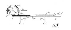
図2に示される第1のステップにおいて、ローラ1およびスクレーパ3はいわゆる休止ポジションにある。図2を参照すると当該ポジションにおいてローラ1およびスクレーパ3は、プレート7の最も近い端部11に対して蓄積プレート6の一端部10の左側に配置されている。スクレーパ3は、リップ4の縁部41によって、パウダー材料の初期厚さe1を有するフィルム(またはボリューム(volume))13の一縁部12に隣接している。In the first step shown in FIG. 2, the roller 1 and the scraper 3 are in a so-called rest position. Referring to FIG. 2, the roller 1 and the scraper 3 are disposed on the left side of the one
本明細書において、「高い」、「低い」、「上」および「下」は、図面に示される操作構成要素に関連している。このように、「上側」部分はこれら図面において上方に面している。 In the present specification, “high”, “low”, “top” and “bottom” relate to the operational components shown in the drawings. Thus, the “upper” portion faces upward in these drawings.
ある量のフィルム13の上面130は、プレート7の上面70に平行な平面上にありかつ上面70の上に存在する。シリンダ1は所定の速度に基づいてシリンダ1の軸Aの周囲で回転する。この回転F1は、パウダー材料14の特性に応じて、三角法方向または逆三角法方向に実施される。回転速度は、スクレーパ3、カバー5およびシリンダ1の組立体が取り付けられる運搬体の線形移送移動速度に左右される。シリンダの接線方向速度は、運搬体の線速度(linear speed)と同期しており、その同期の比率の範囲は、−100から0までおよび0から100まで変化する。同期比率は、パウダー材料の物理化学特性に依存する。A certain amount of the
シリンダの接線方向速度が、シリンダを駆動する運搬体の線速度と同じ方向のものであり、かつ、1の同期比率である(つまり速度が同じ)場合に、パウダー材料14の表面上におけるシリンダ1の母線(generatrix)の移動が生じる。パウダー材料表面におけるシリンダ1の母線の移動速度は、運搬体の線速度の2倍である。 Cylinder 1 on the surface of
シリンダの接線方向速度が、シリンダを駆動する運搬体の線速度と同じ方向のものであり、かつ、1の同期比率である場合に、パウダー材料14の表面上におけるシリンダ1の母線(generatrix)の移動は生じない。言い換えると、この平面上ではシリンダが滑ることなく、この平面上におけるシリンダ1の回転が認められる。 When the cylinder tangential velocity is in the same direction as the linear velocity of the carrier that drives the cylinder and is at a synchronization ratio of 1, the generatrix of the cylinder 1 on the surface of the
シリンダ1の接線方向の速度と運搬体の線速度との比は、パウダー材料14の特性ならびに製造されるフィルムの厚さに適したものである。 The ratio between the tangential speed of the cylinder 1 and the linear speed of the carrier is suitable for the properties of the
シリンダ1の回転と同時に、カバー5、ひいてはスクレーパ3が降下される。この動作は、例えば、シリンダ1のF1に沿う回転の方向とは反対の方向における、図3における矢印F4に沿う枢軸回動によって引き起こされる。カバー5の枢軸回動は、水平軸Bの周囲で実施される。図示されない一実施形態によれば、カバー5は、垂直並進移動によって降下させられる。シリンダ1およびスクレーパ3の移動の同期は、フィルム形成サイクルタイムを低減することができる。必要であれば、シリンダ1およびスクレーパ3の動作は時間とともにオフセットされる。Simultaneously with the rotation of the cylinder 1, the cover 5, and consequently the scraper 3, is lowered. This operation, for example, the direction of rotation along the F1 of the cylinder 1 in the opposite direction, caused by a pivot rotation along the arrow F4 in FIG. 3. The pivoting of the cover 5 is performed around the horizontal axis B. According to one embodiment not shown, the cover 5 is lowered by vertical translation. The synchronization of the movement of the cylinder 1 and the scraper 3 can reduce the film formation cycle time. If necessary, the operation of the cylinder 1 and the scraper 3 is offset with time.
シリンダ1、カバー5およびスクレーパ3を備える組立体は、水平方向直線方向に並進状態で移動させられる。パウダーのフィルム(またはボリューム)13の上面130は、図2に示されるように、縁部41の位置に比べてより高い位置に配置されている。このため、スクレーパ3は、所定の量のパウダー材料を取り出す(抽出する)。組立体の移動は、プレート7の主平面P1に平行な方向F5に沿って水平方向に実施され、かつその方向において、プレート6上の縁部41の水平方向動作によって生じる水平面を基準とする。カバー5の下降により、平面P1は、シリンダ1の下降母線Gに接触する平面P2の下側に位置させられる。言い換えると、図3に示されるこのポジションにおいて、スクレーパ3は、回転ローラ1がパウダー材料14と接触することなく、プレート7の方向への、そのvoryu0mu13における、面130の下での、抽出パウダー材料14の矢印F5に沿った押し出しに適している。なぜならシリンダ1の母線Gは、平面P1上に位置しているからである。The assembly including the cylinder 1, the cover 5, and the scraper 3 is moved in a translational state in the horizontal linear direction. The
したがってスクレーパ3は、蓄積領域6の第1の端部のうちの、所定量のパウダーを蓄積領域6の第2の端部11まで押し出す。スクレーパ3によって押し出されたパウダー14の量は、平面P1とボリューム13の上面130との間の差によって規定される。この差はプレート6の昇降によって変更できることを理解されたい。Accordingly, the scraper 3 pushes a predetermined amount of powder out of the first end portion of the
矢印F5に沿った移送動作は、パウダー材料の特性および/または最終層の所望の特性に基づいて選択された所定の速度で実施される。例えば、この速度は、供給領域上のシリンダ1およびスクレーパ3の移動に関しておおむね0.05m/sから1m/sの間である。Transfer operation along the arrow F5 is carried out at a predetermined speed which is selected based on the desired properties of the characteristics and / or final layer of the powder material. For example, this speed is generally between 0.05 m / s and 1 m / s for the movement of cylinder 1 and scraper 3 over the feed area.
この実施形態において、スクレーパ3およびシリンダ1は、スクレーパ3とシリンダ1との間に一定の距離Eを保ちつつ、同じ速度で横方向に移動する。これは、シリンダ1およびカバー5のそれぞれの回転軸AおよびBを規定する共通の部材(つまり運搬体(図示せず))を設けることによって実施可能となる。 In this embodiment, the scraper 3 and the cylinder 1 move laterally at the same speed while maintaining a certain distance E between the scraper 3 and the cylinder 1. This can be implemented by providing a common member (that is, a carrier (not shown)) that defines the rotation axes A and B of the cylinder 1 and the cover 5, respectively.
一実施形態において、スクレーパ3は、シリンダ1の支持部材と一体化された部材に取り付けられておらず、スクレーパ3およびシリンダ1の移動速度は、フィルム形成段階に応じて異なっておりかつ変更されてもよい。言い換えると、距離Eは、シリンダ1とスクレーパ3との間で変更される。 In one embodiment, the scraper 3 is not attached to a member integrated with the support member of the cylinder 1, and the moving speed of the scraper 3 and the cylinder 1 is different and changed depending on the film forming stage. Also good. In other words, the distance E is changed between the cylinder 1 and the scraper 3.
フレームに設けられた堅固な領域15はプレート6,7を接続し、かつプレート6および7の間においてボリューム13から抽出されたパウダーの通路となり得る。この領域15は、平面P1と平行な平面P3上に、かつその平面より下方に配置されている。言い換えると、この平面P3は、プレート7上に配置されたパウダー材料からなるフィルムの下面によって規定される。A
スクレーパ3が、図4に示されるように、プレート6の端部11に面して位置するプレート7の端部に向けてパウダー14を押し出した場合、カバー5は、スクレーパ3を上昇させるために、カバー5の第1の枢軸回動とは反対の方向において矢印F6に沿って軸Bを中心として枢軸回動する。図5に示されるポジションにおいて、所定の量のパウダー14の堆積物Tは、堆積領域7上に広げられるように、端部16に隣接して配置されている。As shown in FIG. 4, when the scraper 3 pushes the
作業サイクルの開始から(つまりスクレーパ3がパウダー14を押し出すために下降される前に)シリンダ1が軸Aを中心として回転するが、その開始からの休止時間(アイドルタイム)は存在しない。シリンダ1は、スクレーパ3が上昇させられるとすぐに動作可能となっている。スクレーパ3の上昇は、シリンダ1およびカバー5の組立体の移動の停止のみを要求する。とはいえ、この停止時間は、さまざまなサーボ−コントロールデバイスの間および/または予想される操作速度の間における同期に応じて、非常に短くなるか、あるいは存在しないものとなる。 The cylinder 1 rotates about the axis A from the start of the work cycle (that is, before the scraper 3 is lowered to push out the powder 14), but there is no idle time from that start. The cylinder 1 is operable as soon as the scraper 3 is raised. Raising the scraper 3 requires only stopping the movement of the cylinder 1 and cover 5 assembly. Nevertheless, this stop time can be very short or non-existent depending on the synchronization between the various servo-control devices and / or the expected operating speed.
カバー5は、スクレーパ3のリップ4がパウダー14の堆積物Tの上方に位置しかつシリンダ1の動作を妨害しないよう、持ち上げられる。 The cover 5 is lifted so that the lip 4 of the scraper 3 is located above the deposit T of
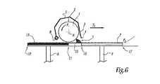
図6に示されるように、F1に沿って回転するローラ1は、端部11からプレート7の端部17の端部へ向けて、領域6上での移動中での速度とは異なる所定の速度でF5に沿って水平並進移動を行う。この移動により、今までプレート6上に配置されていたシリンダ1は、そのシリンダ表面2において堆積物Tと接触するようになる。As shown in FIG. 6, the roller 1 rotating along F1 has a predetermined speed different from the speed during movement on the
図7には、シリンダ1を使用して、続いて配置されたフィルム自体の形成、つまり堆積領域7上のパウダー材料14の拡散が示されている。このフィルムの形成は、F1に沿って回転するシリンダ1の矢印F5に沿う並進動作によって均一に実施される。FIG. 7 shows the formation of the subsequently placed film itself, ie the diffusion of the
この段階の間に、シリンダ1は、シリンダの前後においてパウダー14を拡散するよう押圧する。平面P1に並行なシリンダ1の回転および移動は、パウダー14を所定の厚さのフィルム13’となるよう拡散可能とする。シリンダ1の表面2は、滑らかでありかつその外観上の粗さは低く、また氷のようにつやのある表面に似ており、ローラ1のシリンダ状表面2上にパウダー14が付着することを防止する。これにより、幾何学的精度、シリンダ1の表面状態、および/またはパウダーの粒サイズに関して、約1μmの最小厚さを有し、均質でありかつ基準通りのフィルム13’を得ることが可能となる。上記例においては、実現可能な最小厚さは約5μmである。10μmより大きな厚さを有するフィルムを製造することもできる。During this stage, the cylinder 1 presses to spread the
フィルム形成中に、シリンダ1のシリンダ表面2は、レーザーを使用してあらかじめ焼結されるかあるいは溶解されたフィルムの平面P1と接触しない。この接触しない状態は、特にパウダーフィルムの均一さおよびコンパクトさ、ならびにその粒サイズおよび粒度に左右される。During film formation, the cylinder surface 2 of the cylinder1 is not in contact with the plane P1 of the film that has been pre-sintered or melted using a laser. This non-contact condition depends in particular on the uniformity and compactness of the powder film and its grain size and grain size.
パウダー材料14からなるフィルムの形成は、単一焼結において、つまりシリンダ1およびスクレーパ3の単一戻り移行(passage)において実施されてもよい。成形(compacting)の前に拡散されたパウダーからなる最終的なフィルムを形成するために、拡散されたフィルムの物理化学特性および/または期待品質および/またはあらかじめ決められた厚さに基づいて、複数回の焼結を実施することができる、つまり複数回の上記移行を実施することができる。この場合において、第1のフィルムの厚さと最終フィルムの厚さとの間の中間厚さを有するフィルムが形成される。 The formation of the film of
焼結n中に形成される中間フィルムの厚さは、式:(ax+b)/(cx+d)に基づいて規定される変動に影響されてもよい。それは、2つの中間フィルムの間の厚さの他のタイプの変動を、おおむね漸進的に、成形前にフィルム13’の所望の最終厚さへ到達させるために作用させることができる。 The thickness of the intermediate film formed during sintering n may be affected by variations defined based on the formula: (ax + b) / (cx + d). It can act to cause other types of thickness variations between the two intermediate films, generally progressively, to reach the desired final thickness of the film 13 'prior to forming.
ここで第1のフィルムを堆積させるための第1の移行(つまり第1の焼結)について述べるが、パウダー材料フィルムの消耗の厚さが得られるまでは後に続く焼結も同様であることを理解されたい。有利なことに、成形前に、堆積領域上に堆積されたパウダー材料からなるフィルムの厚さは、成形された最終フィルムの厚さよりも大きい。好ましくは、この厚さは、成形された最終フィルムの厚さの少なくとも2倍である。 The first transition (ie, first sintering) for depositing the first film will now be described, but the subsequent sintering is similar until the thickness of the powder material film wear is obtained. I want you to understand. Advantageously, before forming, the thickness of the film made of powder material deposited on the deposition area is greater than the thickness of the final film formed. Preferably, this thickness is at least twice the thickness of the final film formed.
この第1の焼結中において、層13’の厚さは、最終的なフィルム13”の所望の厚さよりも大きい。 During this first sintering, the thickness of layer 13 'is greater than the desired thickness of the
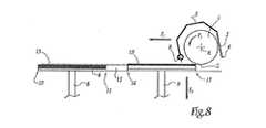
図8において、ローラ1は、プレート7の端部17に到達しており、かつ堆積領域7上においてフィルム13’におけるパウダー材料14の最終的な拡散を行っている。このポジションにおいて、シリンダ1は連続的に回転しており、かつスクレーパ3は持ち上げられている。この拡散段階は完了している。 In FIG. 8, the roller 1 has reached the
シリンダ1、スクレーパ3およびカバー5の組立体は、図6に示されるポジションに、つまり堆積領域7の端部16に戻ってくる。矢印F7に沿う戻り工程中において、ローラ1の回転は保持されたままである。F7に沿う移動は、F5に沿う初期移動時の速度に比べて高い速度で実施される。一実施形態において、矢印F5およびF7に沿った移動速度は同じである。方向F5に沿う移動速度は各焼結間では変更されてもよい。The assembly of the cylinder 1, the scraper 3 and the cover 5 returns to the position shown in FIG. During the return step along arrows F7, rotation of the roller 1 is kept held. Movement along the F7 is performed at a higher speed than the speed during the initial movement along the F5. In one embodiment, the speed of movement along arrows F5 and F7 is the same. Moving velocity along the direction F5 may be changed between each sintering.
この戻り移動中において、プレート7のプランジャ9は、回転ローラ1があらかじめ広げられたフィルム13’と接触しないように、数十ミクロンで矢印F3に沿って下降させられる。During this return movement, the plunger 9 of the plate 7, such that the rotation roller 1 does not contact with the film 13 'which is widened in advance, is lowered along the arrow F3 in several tens of microns.
図9に示されるように、連続的に回転するカバー5およびシリンダ1の組立体の矢印F5に沿った第2の並進移動は、あらかじめ堆積されたパウダー14からなるフィルム13’を成形する。この移動の速度は、付加的には、領域6および7上の先行並進移動中における速度と等しくてもよい。このため、堆積領域7のプランジャ9は、堆積されたフィルム13’の下面(つまりプレートに何もないときのプレート7の上面70)とシリンダ1の下方母線Gとの間の距離がフィルム13”の所望の最終厚さと等しくなるような値まで上昇させられる。As shown in FIG. 9, the second translational movement along the arrow F5 of the continuously rotating cover 5 and cylinder 1 assembly forms a
この厚さdは、スクレーパ3は上昇ポジションに保持された状態で、図10に示されるようにシリンダ1の回転のF5に沿った並進移動による単一の移行で実施されてもよい。この成形段階は、パウダー材料14に応じて所望の回数だけ繰り返される。特に、成形されたフィルム13”の所望の厚さdを得るための所望の移行の回数は、パウダー14の物理化学特性、パウダーの粒サイズおよび/または粒度に左右される。言い換えると、パウダー材料14からなるフィルム13”の所望の厚さを得ることを意図された数学的数列は、減少非線形数列(decreasing non-linear progression)である、つまり(ax+b)/(cx+d)タイプのものである。この数列は、広げられたフィルムの所定の厚さを得るために意図された数列と類似している。This thickness d may be implemented in a single transition by translational movement along F5 of rotation of the cylinder 1 as shown in FIG. 10 with the scraper 3 held in the raised position. This molding step is repeated as many times as desired depending on the
実施される成形は、製造される対象物の構成要素のそれぞれの厚さに基づいて計算される。この厚さは、対象物の高さおよび対象物を製造するために必要なフィルムの数に左右される。フィルムにおけるパウダー密度の変動が原因となって、成形された最終的なフィルムの厚さdは、規定の成形比に応じた厚さの割合によって増大される対象物の構成要素をなすフィルムの厚さと等しくなる。 The molding performed is calculated based on the thickness of each of the components of the object being manufactured. This thickness depends on the height of the object and the number of films required to produce the object. Due to variations in powder density in the film, the final film thickness d formed is increased by the ratio of the thickness according to the specified forming ratio. Is equal to
成形中に、ローラ1のシリンダ表面2は、堆積領域7の表面上のパウダー14のスライド摩擦係数よりも小さなパウダー14におけるスライド摩擦係数Fgを有する必要がある。この方法においてはパウダー材料14は、成形中に堆積領域7上に堆積されたままとなりかつ回転ローラ1によって移動させられない。有利なことに、スライド摩擦係数Fgは約0.02である。 During molding, the cylinder surface 2 of the roller 1 needs to have a sliding friction coefficient Fg in the
図11に示されるようにお成形が実施される際に、ローラ1は堆積領域7の端部17を越えて位置させられており、同様の配置が図8に示されている。シリンダ1は、スクレーパ3が持ち上げられた状態で回転している。一方で、図8に示される配置と比較すると、シリンダ表面2がプレート7の上面70に近接している。 When molding is performed as shown in FIG. 11, the roller 1 is positioned beyond the
スクレーパ3およびシリンダ1の組立体はその初期ポジション、つまり図2に示されるように蓄積領域6からパウダー材料14を抽出するために占めるポジションに戻す必要がある。このため、連続的に回転するシリンダ1およびカバー5は、蓄積領域6の端部10まで並進移動F7に沿って戻る(復帰する)ようになっている。The assembly of the scraper 3 and the cylinder 1 needs to be returned to its initial position, that is, the position occupied to extract the
一種の延性パウダーを用いて、方向F7に沿ってシリンダの移動中にパウダーを広げかつ/または成形することもできる。シリンダ1およびカバー5が蓄積領域6の端部に位置するとき、他のフィルム形成サイクルにおいて異なる量のパウダー材料14を押し出すために、スクレーパ3はF4に沿って再び下降させられる。シリンダ1の、その初期ポジションへの復帰移動中に、シリンダ1からフィルム13”を解放するために、堆積領域7のプランジャ9は再び下降させられる(シリンダ1は、連続して回転しており、かつ成形された層13”と接触させられるべきではない)。Using a type of ductile powder, it can be and / or molding spread powder during the movement of the cylinder along the direction F7. When the cylinder 1 and the cover 5 is located at the end of the
フィルム13”が成形されると、三次元的な物体を形成する固体状のフィルムを形成するために、レーザー処理、つまり焼結または溶解処理が実施される(図示せず)。 When the
新しいサイクルにおいては、単純に、フィルム形成サイクルを再開するためにスクレーパ3を下降させる前に供給領域6のプランジャ8を上昇させる必要がある。 In the new cycle, it is simply necessary to raise the plunger 8 in the
図12にはさらなる実施形態が示されており、このものにおいて、例えばシリンダ1と同一の第2のシリンダR2がシリンダ1の近隣に配置されている。2つのシリンダ1およびR2の回転軸は平行である。これらシリンダ1,R2は、それぞれ接触領域(つまりシリンダの下方母線)が異なる高さとなるように配置されている。この高さにおける差異Xは、パウダー14の特性および得られる成形フィルムの厚さに応じて適合される。言い換えるとXは、(ax+b)/(cx+d)タイプの減少非線形的な数列によってもたらされる。 A further embodiment is shown in FIG. 12, in which a second cylinder R 2, for example identical to the cylinder 1, is arranged in the vicinity of the cylinder 1. The rotation axes of the two cylinders 1 and R2 are parallel. The cylinders 1 and R2 are arranged so that the contact areas (that is, the lower bus bars of the cylinders) have different heights. This difference X in height is adapted according to the properties of the
したがって、単一シリンダ1では2回の移行が必要とされるが、第2のシリンダR2を設けることによって、単一の移行において成形を実施することが可能となる。これにより、成形されたフィルム13”を得るのに掛かる時間が低減される。シリンダ1,R2の回転速度および/または回転速度は調節可能である。これらパラメータは付加的にはシリンダ1,R2の両方に関して同一であってもよい。シリンダ1,R2の並進移動パラメータに関しても同様のことが言える。 Therefore, although the single cylinder 1 requires two transitions, by providing the second cylinder R2, it is possible to perform molding in a single transition. This reduces the time taken to obtain the molded
図12においてツールR3がスクレーパ3の付近において概略的に示されている。このツールは較正ツール、例えばミルタイプのツールを構成する。ツールR3は、フィルムにレーザー処理を施した後(つまり成形されたパウダー材料にレーザー溶解または焼結が施された後)のフィルム13”の硬度よりも大きな硬度を有する作業部品(例えば歯)を備えている。このツールR3は、例えば炭化タングステンから形成されてもよい。より明確にするために、レーザーで処置された成形パウダー材料からなるフィルムは、単一ツールR3下に点線で示されている。これは、このフィルムがプレート7の全体に延在していると理解されたい。 In FIG. 12, the tool R3 is schematically shown in the vicinity of the scraper 3. This tool constitutes a calibration tool, for example a mill type tool. Tool R3 removes a work part (for example, a tooth) having a hardness greater than that of
ツールR3は、スクレーパ3と置き換えることにより、付加的なフィルムを形成するためにパウダー14がプレート7上に押し出される際に、あらかじめ形成され、すでにレーザー処理がなされたパウダーフィルム13”の較正を可能にする。 Tool R3 can be replaced with scraper 3 to calibrate
実際に、あらかじめ広げられかつ成形されたフィルムにレーザー焼結または溶解がすでになされている場合、特に切り取りを伴う上記物体の製造の後に、レーザー処理がなされたフィルムの表面上に起伏部または微小な凹凸部が見られてもよい。したがってR3は、次のフィルムの製造の前に数mm3の材料を取り除くことによりフィルムの面を滑らかにすることができる。In fact, if laser sintering or melting has already been done on a pre-rolled and shaped film, especially after the production of the object with a cut-out, there are undulations or microscopic features on the surface of the laser-treated film. An uneven part may be seen. R3 can therefore smooth the surface of the film by removing a few mm3 of material before the next film production.
有利なことに、R3は、シリンダ1,R2およびスクレーパ3と同一の運搬体に取り付けられている。代替実施形態においては、R3は、スクレーパ3およびシリンダ1,R2を支持するための他の運搬体に対して取り外し可能に取り付けられている。 Advantageously, R3 is mounted on the same carrier as cylinders 1, R2 and scraper 3. In an alternative embodiment, R3 is removably attached to the scraper 3 and other carriers for supporting the cylinders 1, R2.
ツールR3の回転速度および移動速度は、パウダー材料14がレーザーを用いて処置される場合、パウダー材料14に適切なものである。 The rotational speed and travel speed of the tool R3 is appropriate for the
シリンダR2,1およびツールR3の移動方向は同じである。 The moving directions of the cylinders R2, 1 and the tool R3 are the same.
図示されていないさらなる実施形態において、シリンダ1、カバー5およびスクレーパ3の組立体は、垂直方向の移動に適したものとなっている。そのため、広げられるパウダー14の量を調節するために、プランジャ8を上昇させかつシリンダ1とカバー5とスクレーパ3との組立体を下降させることができる。 In a further embodiment not shown, the cylinder 1, cover 5 and scraper 3 assembly is suitable for vertical movement. Therefore, in order to adjust the amount of the
ローラ1の連続的な回転は、同様の再位置決めまでサイクルを停止させることなく、ローラの迅速な作動を可能にする。 The continuous rotation of the roller 1 allows for rapid operation of the roller without stopping the cycle until similar repositioning.
シリンダ表面2が成形中に完全に使用されるため、相当な長さのパウダーフィルムを成形することができる。 Since the cylinder surface 2 is completely used during molding, a considerable length of powder film can be molded.
図示されていない実施形態において、カバー5の形状は上記形状とは異なっていてもよい。 In an embodiment not shown, the shape of the cover 5 may be different from the above shape.
代替実施形態において、スクレーパ3は、シリンダの回転軸に連結されたアームに取り付けられていてもよく、シリンダは保護カバーを備えていない。 In an alternative embodiment, the scraper 3 may be attached to an arm connected to the rotation axis of the cylinder, and the cylinder does not have a protective cover.
1 ローラ(シリンダ)
2 シリンダ表面
3 スクレーパ
4 リップ
5 カバー
6 蓄積プレート
7 堆積プレート
8 プランジャ
9 プランジャ
10 プレート6の端部
11 プレート6の端部
12 縁部
13 フィルム
14 パウダー材料
15 堅固な領域15(solid area)
16 プレート7の端部
17 プレート7の端部
31 本体
41 縁部
70 プレート7の上面
13’ フィルム
13” フィルム
130 上面
R2 シリンダ
R3 ツール1 Roller (cylinder)
2 Cylinder surface 3 Scraper 4 Lip 5
16 End of Plate 7 17 End of Plate 7 31
Claims (12)
Translated fromJapanese前記デバイスは、蓄積領域(6)と、堆積領域(7)と、シリンダ(1,R2)であって、前記シリンダ(1)によって前記蓄積領域(6)から前記堆積領域(7)へあらかじめ移動させられた前記パウダー材料(14)を堆積しかつ成形するための円形の側面を有するシリンダ(1,R2)と、を具備しており、
前記デバイスは、:
− 滑らかなシリンダ表面(2)を有するシリンダ(1)であって、前記シリンダはその回転軸(A)の周囲で回転可能に動作できるものであり、かつ、前記蓄積領域(6)と前記堆積領域(7)との間において、前記堆積領域(7)における主平面(P1)に平行な少なくとも1つの方向(F5,F7)に並進移動可能である、シリンダ(1)と、
− スクレーパ(3)であって、前記スクレーパ(3)が前記蓄積領域(6)上のパウダー材料を所定量だけ抽出する下降ポジションと、前記シリンダが前記パウダー材料を拡散しかつ成形できるよう適合された上昇ポジションとの間で、前記堆積領域(7)の前記主平面(P1)に直交する方向(F4,F6)に移動可能であり、かつ、前記蓄積領域(6)と前記堆積領域(7)との間において、前記シリンダ(1)と同じ方向(F5,F7)に水平直線方向に並進して移動可能であり、前記スクレーパの移動中に一方の前記領域(6)から他方の前記領域(7)へ前記パウダー材料(14)を押し出すのに適合された、スクレーパ(3)と、
を具備してなり、
前記シリンダ(1)の前記シリンダ表面(2)は、0.06μmの外観粗さ(Ra)を有することを特徴とするデバイス。A device adapted to form at least one thin film (13 ″) of powder material (14),
The device is an accumulation area (6), a deposition area (7), and a cylinder (1, R2), and is moved in advance from the accumulation area (6) to the deposition area (7) by the cylinder (1). A cylinder (1, R2) having a circular side surface for depositing and forming the powder material (14) that has been made,
The device is:
A cylinder (1) having a smooth cylinder surface (2), the cylinder being operable to rotate about its axis of rotation (A), and the accumulation area (6) and the deposit A cylinder (1) capable of translational movement between the region (7) and at least one direction (F5 , F7 ) parallel to the main plane (P1 ) in the deposition region (7);
-A scraper (3) adapted to allow the scraper (3) to extract a predetermined amount of powder material on the storage area (6) by a predetermined amount and to allow the cylinder to diffuse and mold the powder material; between the raised position and is movable in the direction (F4, F6) which is perpendicular to the main plane of said deposition area (7) (P1), and the deposition and the accumulation area (6) region between the (7), said cylinder (1) in the same direction (F5, F7) in movable by translation in a horizontal linear direction, one of the regions during the movement of the scraper (6) A scraper (3) adapted to extrude the powder material (14) from one to the other region (7);
Comprising
The cylinder surface (2) of the cylinder (1) has an appearance roughness (Ra) of 0.06 μm.
−a) 前記パウダー材料(14)を蓄積するための領域(6)から上流おいて、少なくとも1つのシリンダ(1,R2)を回転させるステップ(F1)と、
−b) スクレーパ(3)を下降させるステップと、
−c) 前記蓄積領域(6)上において前記スクレーパ(3)を使用して所定の量のパウダー材料(14)を抽出するステップと、
−d) 前記スクレーパ(3)を使用して、前記蓄積領域(6)から堆積領域(7)へ、前記抽出された所定量のパウダー材料を押し出すステップ(F5)と、
−e) 前記スクレーパ(3)を上昇させるステップ(F6)と、
−f) 前記堆積領域(7)上の前記パウダー材料(14)を、前記シリンダ(1)を使用して拡散させるステップと、
−g) あらかじめ拡散されたパウダー材料(14)を、少なくとも1のシリンダ(1)の移行において、前記シリンダ(1)を使用して、成形するステップと、
−h) 所望の数の成形されたフィルム(13”)が製造されるまで、ステップa)からステップg)を繰り返すステップと、
を含むことを特徴とする方法。A method for forming at least one film of powder material using the device according to any one of claims 1 to 9, comprising:
-A) rotating at least one cylinder (1, R2) upstream from the region (6) for storing the powder material (14) (F1 );
-B) lowering the scraper (3);
-C) extracting a predetermined amount of powder material (14) using the scraper (3) on the accumulation area (6);
-D) using said scraper (3), wherein the deposition from the accumulation area (6) area (7), and step (F5) for extruding a predetermined quantity of powder material the extracted,
-E) the step of raising the scraper (3) and (F6),
-F) diffusing the powder material (14) on the deposition area (7) using the cylinder (1);
-G) shaping the pre-diffused powder material (14) using said cylinder (1) in the transition of at least one cylinder (1);
-H) repeating steps a) to g) until the desired number of shaped films (13 ") has been produced;
A method comprising the steps of:
Applications Claiming Priority (2)
| Application Number | Priority Date | Filing Date | Title |
|---|---|---|---|
| FR0903454AFR2948044B1 (en) | 2009-07-15 | 2009-07-15 | THIN-LAYERING DEVICE AND METHOD OF USING SUCH A DEVICE |
| FR09/03454 | 2009-07-15 |
Related Parent Applications (1)
| Application Number | Title | Priority Date | Filing Date |
|---|---|---|---|
| JP2012520069ADivisionJP5977170B2 (en) | 2009-07-15 | 2010-07-12 | Devices for forming thin films and methods for using such devices |
Publications (2)
| Publication Number | Publication Date |
|---|---|
| JP2015120352Atrue JP2015120352A (en) | 2015-07-02 |
| JP5993038B2 JP5993038B2 (en) | 2016-09-14 |
Family
ID=41606653
Family Applications (2)
| Application Number | Title | Priority Date | Filing Date |
|---|---|---|---|
| JP2012520069AActiveJP5977170B2 (en) | 2009-07-15 | 2010-07-12 | Devices for forming thin films and methods for using such devices |
| JP2015007090AActiveJP5993038B2 (en) | 2009-07-15 | 2015-01-16 | Devices for forming thin films and methods for using such devices |
Family Applications Before (1)
| Application Number | Title | Priority Date | Filing Date |
|---|---|---|---|
| JP2012520069AActiveJP5977170B2 (en) | 2009-07-15 | 2010-07-12 | Devices for forming thin films and methods for using such devices |
Country Status (8)
| Country | Link |
|---|---|
| US (1) | US9440285B2 (en) |
| EP (1) | EP2454040B1 (en) |
| JP (2) | JP5977170B2 (en) |
| DK (1) | DK2454040T3 (en) |
| ES (1) | ES2519340T3 (en) |
| FR (1) | FR2948044B1 (en) |
| PL (1) | PL2454040T3 (en) |
| WO (1) | WO2011007087A2 (en) |
Families Citing this family (90)
| Publication number | Priority date | Publication date | Assignee | Title |
|---|---|---|---|---|
| US8992816B2 (en) | 2008-01-03 | 2015-03-31 | Arcam Ab | Method and apparatus for producing three-dimensional objects |
| CN102470439B (en) | 2009-07-15 | 2016-03-02 | 阿卡姆股份公司 | Manufacture the method and apparatus of three-dimensional body |
| FR2984191B1 (en)* | 2011-12-20 | 2014-01-10 | Michelin Soc Tech | MACHINE AND PROCESS FOR ADDITIVE MANUFACTURE OF POWDER |
| US10189086B2 (en) | 2011-12-28 | 2019-01-29 | Arcam Ab | Method and apparatus for manufacturing porous three-dimensional articles |
| EP2797730B2 (en) | 2011-12-28 | 2020-03-04 | Arcam Ab | Method and apparatus for detecting defects in freeform fabrication |
| FR2991208B1 (en) | 2012-06-01 | 2014-06-06 | Michelin & Cie | MACHINE AND PROCESS FOR ADDITIVE MANUFACTURE OF POWDER |
| WO2014071968A1 (en) | 2012-11-06 | 2014-05-15 | Arcam Ab | Powder pre-processing for additive manufacturing |
| DE112013006045T5 (en) | 2012-12-17 | 2015-09-17 | Arcam Ab | Additive manufacturing method and device |
| EP2969485B1 (en)* | 2013-03-15 | 2019-06-05 | 3D Systems, Inc. | Chute for laser sintering systems |
| US9550207B2 (en) | 2013-04-18 | 2017-01-24 | Arcam Ab | Method and apparatus for additive manufacturing |
| US9676031B2 (en) | 2013-04-23 | 2017-06-13 | Arcam Ab | Method and apparatus for forming a three-dimensional article |
| DE102013215053A1 (en)* | 2013-07-31 | 2015-02-05 | Bayerische Motoren Werke Aktiengesellschaft | Device and method for applying a powder layer on a powder platform or on a powder board on a powder platform |
| US9505057B2 (en)* | 2013-09-06 | 2016-11-29 | Arcam Ab | Powder distribution in additive manufacturing of three-dimensional articles |
| US9676032B2 (en) | 2013-09-20 | 2017-06-13 | Arcam Ab | Method for additive manufacturing |
| US10434572B2 (en) | 2013-12-19 | 2019-10-08 | Arcam Ab | Method for additive manufacturing |
| FR3014338B1 (en) | 2013-12-05 | 2015-12-18 | Michelin & Cie | MACHINE AND PROCESS FOR ADDITIVE MANUFACTURE OF POWDER |
| US9802253B2 (en) | 2013-12-16 | 2017-10-31 | Arcam Ab | Additive manufacturing of three-dimensional articles |
| US10130993B2 (en) | 2013-12-18 | 2018-11-20 | Arcam Ab | Additive manufacturing of three-dimensional articles |
| US9789563B2 (en) | 2013-12-20 | 2017-10-17 | Arcam Ab | Method for additive manufacturing |
| EP4624072A1 (en) | 2014-01-09 | 2025-10-01 | RTX Corporation | Material and processes for additively manufacturing one or more parts |
| EP3094435B1 (en)* | 2014-01-14 | 2022-07-13 | Raytheon Technologies Corporation | System and process for distributing material during additive manufacturing |
| US10913129B2 (en) | 2014-01-24 | 2021-02-09 | Raytheon Technologies Corporation | Additive manufacturing an object from material with a selective diffusion barrier |
| EP3096939B1 (en) | 2014-01-24 | 2021-08-25 | Raytheon Technologies Corporation | Monitoring material solidification byproducts during additive manufacturing |
| EP3096909B1 (en) | 2014-01-24 | 2024-11-27 | RTX Corporation | Alloying metal materials together during additive manufacturing of one or more parts |
| WO2015112723A1 (en) | 2014-01-24 | 2015-07-30 | United Technologies Corporation | Conditioning one or more additive manufactured objects |
| US9950392B2 (en) | 2014-03-04 | 2018-04-24 | Rohr, Inc. | Forming one or more apertures in a fiber-reinforced composite object with a laser |
| US9789541B2 (en) | 2014-03-07 | 2017-10-17 | Arcam Ab | Method for additive manufacturing of three-dimensional articles |
| US20150283613A1 (en) | 2014-04-02 | 2015-10-08 | Arcam Ab | Method for fusing a workpiece |
| JP6390162B2 (en)* | 2014-05-16 | 2018-09-19 | 株式会社リコー | 3D modeling equipment |
| JP6379684B2 (en)* | 2014-06-02 | 2018-08-29 | 株式会社リコー | 3D modeling equipment |
| US9486878B2 (en) | 2014-06-20 | 2016-11-08 | Velo3D, Inc. | Apparatuses, systems and methods for three-dimensional printing |
| DE102014212176A1 (en)* | 2014-06-25 | 2015-12-31 | Siemens Aktiengesellschaft | Powder bed-based additive manufacturing process and apparatus for carrying out this process |
| US9310188B2 (en) | 2014-08-20 | 2016-04-12 | Arcam Ab | Energy beam deflection speed verification |
| JP6432236B2 (en)* | 2014-09-17 | 2018-12-05 | 富士ゼロックス株式会社 | Powder coating apparatus and powder coating method |
| CN104325140B (en)* | 2014-11-18 | 2015-08-19 | 韶关学院 | Precinct laser fusion increases the flexible spreading methods of material manufacture metal dust and device |
| JP6498922B2 (en)* | 2014-12-08 | 2019-04-10 | 株式会社アスペクト | Powder additive manufacturing apparatus and powder additive manufacturing method |
| US10786865B2 (en) | 2014-12-15 | 2020-09-29 | Arcam Ab | Method for additive manufacturing |
| US10245786B2 (en)* | 2014-12-17 | 2019-04-02 | Xerox Corporation | System for planarizing objects in three-dimensional object printing systems with reduced debris |
| US10144061B2 (en) | 2014-12-30 | 2018-12-04 | Delavan Inc. | Particulates for additive manufacturing techniques |
| US9721755B2 (en) | 2015-01-21 | 2017-08-01 | Arcam Ab | Method and device for characterizing an electron beam |
| DE102015201775A1 (en) | 2015-02-02 | 2016-08-04 | Gkn Sinter Metals Engineering Gmbh | Method and device for the additive production of components |
| JP6474290B2 (en)* | 2015-03-20 | 2019-02-27 | ローランドディー.ジー.株式会社 | 3D modeling equipment |
| US11014161B2 (en) | 2015-04-21 | 2021-05-25 | Arcam Ab | Method for additive manufacturing |
| DE102015109849A1 (en) | 2015-06-19 | 2016-12-22 | Aconity3D Gmbh | Bottom-up powder conveying mechanism for a PBLS plant, PBLS plant and process for converting and operating a PBLS plant |
| DE102015109841A1 (en)* | 2015-06-19 | 2016-12-22 | Aconity3D Gmbh | Powder coating unit for a PBLS plant and process for applying two consecutive powder layers in a PBLS process |
| US10807187B2 (en) | 2015-09-24 | 2020-10-20 | Arcam Ab | X-ray calibration standard object |
| US10583483B2 (en) | 2015-10-15 | 2020-03-10 | Arcam Ab | Method and apparatus for producing a three-dimensional article |
| US10065270B2 (en) | 2015-11-06 | 2018-09-04 | Velo3D, Inc. | Three-dimensional printing in real time |
| US10525531B2 (en) | 2015-11-17 | 2020-01-07 | Arcam Ab | Additive manufacturing of three-dimensional articles |
| US10610930B2 (en) | 2015-11-18 | 2020-04-07 | Arcam Ab | Additive manufacturing of three-dimensional articles |
| US10286603B2 (en) | 2015-12-10 | 2019-05-14 | Velo3D, Inc. | Skillful three-dimensional printing |
| US20170239719A1 (en) | 2016-02-18 | 2017-08-24 | Velo3D, Inc. | Accurate three-dimensional printing |
| US11247274B2 (en) | 2016-03-11 | 2022-02-15 | Arcam Ab | Method and apparatus for forming a three-dimensional article |
| EP3429819B1 (en) | 2016-03-14 | 2021-04-14 | Nanogrande | Method and apparatus for forming layers of particles for use in additive manufacturing |
| US11325191B2 (en) | 2016-05-24 | 2022-05-10 | Arcam Ab | Method for additive manufacturing |
| US10549348B2 (en) | 2016-05-24 | 2020-02-04 | Arcam Ab | Method for additive manufacturing |
| US10525547B2 (en) | 2016-06-01 | 2020-01-07 | Arcam Ab | Additive manufacturing of three-dimensional articles |
| US11691343B2 (en) | 2016-06-29 | 2023-07-04 | Velo3D, Inc. | Three-dimensional printing and three-dimensional printers |
| EP3492244A1 (en) | 2016-06-29 | 2019-06-05 | VELO3D, Inc. | Three-dimensional printing system and method for three-dimensional printing |
| DE102016211952A1 (en)* | 2016-06-30 | 2018-01-04 | Eos Gmbh Electro Optical Systems | Coating unit, coating method, apparatus and method for generatively producing a three-dimensional object |
| DE102016211949A1 (en)* | 2016-06-30 | 2018-01-04 | Eos Gmbh Electro Optical Systems | Coating unit, coating method, apparatus and method for generatively producing a three-dimensional object |
| US20180093418A1 (en) | 2016-09-30 | 2018-04-05 | Velo3D, Inc. | Three-dimensional objects and their formation |
| US10792757B2 (en) | 2016-10-25 | 2020-10-06 | Arcam Ab | Method and apparatus for additive manufacturing |
| US20180126460A1 (en) | 2016-11-07 | 2018-05-10 | Velo3D, Inc. | Gas flow in three-dimensional printing |
| US10987752B2 (en) | 2016-12-21 | 2021-04-27 | Arcam Ab | Additive manufacturing of three-dimensional articles |
| US20180186082A1 (en) | 2017-01-05 | 2018-07-05 | Velo3D, Inc. | Optics in three-dimensional printing |
| US10315252B2 (en) | 2017-03-02 | 2019-06-11 | Velo3D, Inc. | Three-dimensional printing of three-dimensional objects |
| US10449696B2 (en) | 2017-03-28 | 2019-10-22 | Velo3D, Inc. | Material manipulation in three-dimensional printing |
| EP3565709B1 (en)* | 2017-04-21 | 2023-07-12 | Hewlett-Packard Development Company, L.P. | Recoater movement |
| US11059123B2 (en) | 2017-04-28 | 2021-07-13 | Arcam Ab | Additive manufacturing of three-dimensional articles |
| US11292062B2 (en) | 2017-05-30 | 2022-04-05 | Arcam Ab | Method and device for producing three-dimensional objects |
| US11185926B2 (en) | 2017-09-29 | 2021-11-30 | Arcam Ab | Method and apparatus for additive manufacturing |
| US11225016B2 (en)* | 2017-10-20 | 2022-01-18 | Hewlett-Packard Development Company, L.P. | Additive manufacturing layers |
| US10529070B2 (en) | 2017-11-10 | 2020-01-07 | Arcam Ab | Method and apparatus for detecting electron beam source filament wear |
| US10821721B2 (en) | 2017-11-27 | 2020-11-03 | Arcam Ab | Method for analysing a build layer |
| US11072117B2 (en) | 2017-11-27 | 2021-07-27 | Arcam Ab | Platform device |
| UA127741C2 (en)* | 2017-12-07 | 2023-12-20 | Сальфорд Гроуп Інк | Spreader for particulate material with improved spread control |
| US11517975B2 (en) | 2017-12-22 | 2022-12-06 | Arcam Ab | Enhanced electron beam generation |
| US12350754B2 (en) | 2017-12-22 | 2025-07-08 | Arcam Ab | Electron beam source and the use of the same |
| US10272525B1 (en) | 2017-12-27 | 2019-04-30 | Velo3D, Inc. | Three-dimensional printing systems and methods of their use |
| US10144176B1 (en) | 2018-01-15 | 2018-12-04 | Velo3D, Inc. | Three-dimensional printing systems and methods of their use |
| US11267051B2 (en) | 2018-02-27 | 2022-03-08 | Arcam Ab | Build tank for an additive manufacturing apparatus |
| US10800101B2 (en) | 2018-02-27 | 2020-10-13 | Arcam Ab | Compact build tank for an additive manufacturing apparatus |
| US11400519B2 (en) | 2018-03-29 | 2022-08-02 | Arcam Ab | Method and device for distributing powder material |
| US11192302B2 (en) | 2018-10-31 | 2021-12-07 | Carbon, Inc. | Apparatuses for additively manufacturing three-dimensional objects |
| CN113518703B (en)* | 2019-06-25 | 2023-04-04 | 惠普发展公司,有限责任合伙企业 | Roller control for 3D printer |
| CA3148849A1 (en) | 2019-07-26 | 2021-02-04 | Velo3D, Inc. | Quality assurance in formation of three-dimensional objects |
| DE102020211637A1 (en)* | 2020-09-17 | 2022-03-17 | Robert Bosch Gesellschaft mit beschränkter Haftung | Coating system for an additive manufacturing system |
| CN112620659B (en)* | 2020-12-11 | 2022-08-30 | 西安增材制造国家研究院有限公司 | Powder scraping device for high-temperature printing system |
| CN117047122A (en)* | 2023-08-07 | 2023-11-14 | 首都航天机械有限公司 | Device for replacing damaged rubber scraper belt |
Citations (5)
| Publication number | Priority date | Publication date | Assignee | Title |
|---|---|---|---|---|
| JPH07507508A (en)* | 1992-06-05 | 1995-08-24 | マサチユーセツツ・インステイテユート・オブ・テクノロジー | three dimensional printing techniques |
| JP2001038274A (en)* | 1999-05-21 | 2001-02-13 | Agency Of Ind Science & Technol | Method for leveled film formation of superfine particle material |
| JP2002503632A (en)* | 1998-02-19 | 2002-02-05 | エコール.ナショナール.シュペリエール.ド.セラミーク.インドストリエル | Method and apparatus for rapid formation of prototype by laser sintering of powder |
| JP2003531714A (en)* | 1999-12-10 | 2003-10-28 | エコール.ナショナール.シュペリエール.ド.セラミーク.インドストリエル | Apparatus and method for depositing thin layers of powdered or finely divided material |
| JP2007516342A (en)* | 2003-06-30 | 2007-06-21 | フェニックス システムズ | An apparatus for producing a thin powder layer by processing based on the action of a laser on the material, especially at high temperatures |
Family Cites Families (19)
| Publication number | Priority date | Publication date | Assignee | Title |
|---|---|---|---|---|
| US4752352A (en)* | 1986-06-06 | 1988-06-21 | Michael Feygin | Apparatus and method for forming an integral object from laminations |
| US5876550A (en) | 1988-10-05 | 1999-03-02 | Helisys, Inc. | Laminated object manufacturing apparatus and method |
| US5474719A (en)* | 1991-02-14 | 1995-12-12 | E. I. Du Pont De Nemours And Company | Method for forming solid objects utilizing viscosity reducible compositions |
| DE4300478C2 (en)* | 1993-01-11 | 1998-05-20 | Eos Electro Optical Syst | Method and device for producing a three-dimensional object |
| AU4971396A (en)* | 1995-02-01 | 1996-08-21 | 3D Systems, Inc. | Rapid recoating of three-dimensional objects formed on a cross-sectional basis |
| DE19514740C1 (en)* | 1995-04-21 | 1996-04-11 | Eos Electro Optical Syst | Appts. for producing three-dimensional objects by laser sintering |
| DE69604043T2 (en)* | 1995-11-09 | 2000-04-13 | Toyota Jidosha K.K., Toyota | Process for producing a mold from layers and a casting made therewith |
| IT1277079B1 (en)* | 1995-12-14 | 1997-11-04 | Geld & Kapitalanlagen Ag | MACHINE FOR FORMING COSMETIC PRODUCT TABLETS |
| WO1998043762A2 (en)* | 1997-03-31 | 1998-10-08 | Therics, Inc. | Method for dispensing of powders |
| FR2790418B1 (en)* | 1999-03-01 | 2001-05-11 | Optoform Sarl Procedes De Prot | RAPID PROTOTYPING PROCESS ALLOWING THE USE OF PASTY MATERIALS, AND DEVICE FOR IMPLEMENTING SAME |
| US6827634B2 (en) | 2000-05-22 | 2004-12-07 | Agency Of Industrial Science And Technology | Ultra fine particle film forming method and apparatus |
| TWI228114B (en)* | 1999-12-24 | 2005-02-21 | Nat Science Council | Method and equipment for making ceramic work piece |
| US6548014B2 (en)* | 2000-06-21 | 2003-04-15 | Sumitomo Special Metals Co., Ltd. | Suspension application apparatus and method for manufacturing rare earth magnet |
| US20020093115A1 (en) | 2001-01-12 | 2002-07-18 | Jang B. Z. | Layer manufacturing method and apparatus using a programmable planar light source |
| US6780368B2 (en) | 2001-04-10 | 2004-08-24 | Nanotek Instruments, Inc. | Layer manufacturing of a multi-material or multi-color 3-D object using electrostatic imaging and lamination |
| US6722528B2 (en)* | 2002-03-14 | 2004-04-20 | Fisher Controls International, Inc. | Rotary pneumatic actuator |
| US20050263934A1 (en)* | 2004-05-28 | 2005-12-01 | 3D Systems, Inc. | Single side feed parked powder wave heating with wave flattener |
| JP2006205456A (en) | 2005-01-26 | 2006-08-10 | Toyota Motor Corp | Powder supply equipment for powder additive manufacturing |
| KR100925363B1 (en) | 2007-05-30 | 2009-11-09 | 파나소닉 전공 주식회사 | Lamination Molding Device |
- 2009
- 2009-07-15FRFR0903454Apatent/FR2948044B1/enactiveActive
- 2010
- 2010-07-12WOPCT/FR2010/051464patent/WO2011007087A2/enactiveApplication Filing
- 2010-07-12ESES10751997.7Tpatent/ES2519340T3/enactiveActive
- 2010-07-12JPJP2012520069Apatent/JP5977170B2/enactiveActive
- 2010-07-12PLPL10751997Tpatent/PL2454040T3/enunknown
- 2010-07-12EPEP10751997.7Apatent/EP2454040B1/enactiveActive
- 2010-07-12DKDK10751997.7Tpatent/DK2454040T3/enactive
- 2010-07-12USUS13/384,025patent/US9440285B2/enactiveActive
- 2015
- 2015-01-16JPJP2015007090Apatent/JP5993038B2/enactiveActive
Patent Citations (5)
| Publication number | Priority date | Publication date | Assignee | Title |
|---|---|---|---|---|
| JPH07507508A (en)* | 1992-06-05 | 1995-08-24 | マサチユーセツツ・インステイテユート・オブ・テクノロジー | three dimensional printing techniques |
| JP2002503632A (en)* | 1998-02-19 | 2002-02-05 | エコール.ナショナール.シュペリエール.ド.セラミーク.インドストリエル | Method and apparatus for rapid formation of prototype by laser sintering of powder |
| JP2001038274A (en)* | 1999-05-21 | 2001-02-13 | Agency Of Ind Science & Technol | Method for leveled film formation of superfine particle material |
| JP2003531714A (en)* | 1999-12-10 | 2003-10-28 | エコール.ナショナール.シュペリエール.ド.セラミーク.インドストリエル | Apparatus and method for depositing thin layers of powdered or finely divided material |
| JP2007516342A (en)* | 2003-06-30 | 2007-06-21 | フェニックス システムズ | An apparatus for producing a thin powder layer by processing based on the action of a laser on the material, especially at high temperatures |
Also Published As
| Publication number | Publication date |
|---|---|
| JP5993038B2 (en) | 2016-09-14 |
| DK2454040T3 (en) | 2014-09-22 |
| JP5977170B2 (en) | 2016-08-24 |
| EP2454040B1 (en) | 2014-09-03 |
| FR2948044B1 (en) | 2014-02-14 |
| WO2011007087A2 (en) | 2011-01-20 |
| FR2948044A1 (en) | 2011-01-21 |
| EP2454040A2 (en) | 2012-05-23 |
| JP2012532995A (en) | 2012-12-20 |
| WO2011007087A3 (en) | 2012-01-19 |
| ES2519340T3 (en) | 2014-11-06 |
| US20120164322A1 (en) | 2012-06-28 |
| PL2454040T3 (en) | 2015-03-31 |
| US9440285B2 (en) | 2016-09-13 |
Similar Documents
| Publication | Publication Date | Title |
|---|---|---|
| JP5993038B2 (en) | Devices for forming thin films and methods for using such devices | |
| US10780497B2 (en) | Material dispensing and compaction in additive manufacturing | |
| CN109219490B (en) | Method and apparatus for additive manufacturing with powder materials | |
| US10766802B2 (en) | Flexible 3D freeform techniques | |
| EP3174652B1 (en) | Powder additive method for manufacturing a part, in particular a sipe for lining a tyre mould | |
| EP3215349A1 (en) | Machine and method for powder-based additive manufacturing | |
| EP3849781B1 (en) | A recoating device and method for applying a layer of build material capable of solidification on a working surface | |
| WO2004037469A1 (en) | Method and apparatus for rapid manufacturing of metal, ceramic and metal-ceramic products | |
| WO2010038322A1 (en) | Device for continuously forming unfired ceramic formed bodies | |
| US10675683B2 (en) | Laminar vertical powder flow for additive manufacturing | |
| GB2196623A (en) | Fluid-permeable article and method for producing the same | |
| FR3070134B1 (en) | METHOD AND MACHINE FOR MANUFACTURING AT LEAST ONE PIECE OF AT LEAST ONE CERAMIC AND / OR METALLIC MATERIAL BY THE TECHNIQUE OF ADDITIVE PROCESSES | |
| JPH09506553A (en) | Device and method for manufacturing three-dimensional object by laser sintering | |
| EP0614737A1 (en) | Dome shaped extrusion dies | |
| CN105880590A (en) | Additive manufacturing system capable of achieving continuous formation | |
| JPH11267891A (en) | Powder filling method and powder supply device in powder molding press | |
| CN112188962A (en) | Method of preparing powder bed deposited additive manufacturing platform upper surface | |
| US11225016B2 (en) | Additive manufacturing layers | |
| CN115625348A (en) | A powder mixing-adding material-stamping compound forming device and method | |
| CN114505498A (en) | Laser rapid prototyping method and device easy for entity separation | |
| FR3070135A1 (en) | METHOD AND MACHINE FOR MANUFACTURING PARTS OF CERAMIC OR METALLIC MATERIAL BY THE TECHNIQUE OF ADDITIVE PROCESSES | |
| CN216708363U (en) | Self-compaction powder laying assembly and laser rapid forming device | |
| EP3986699B1 (en) | Recoater for a three-dimensional printer, three-dimensional printer and process for three-dimensional printing of grained material | |
| SU1084115A1 (en) | Apparatus for producing double-layer articles of tubular shape | |
| JP2005206430A (en) | Mold press machine and manufacturing method of optical element |
Legal Events
| Date | Code | Title | Description |
|---|---|---|---|
| A977 | Report on retrieval | Free format text:JAPANESE INTERMEDIATE CODE: A971007 Effective date:20151111 | |
| A131 | Notification of reasons for refusal | Free format text:JAPANESE INTERMEDIATE CODE: A131 Effective date:20151120 | |
| A601 | Written request for extension of time | Free format text:JAPANESE INTERMEDIATE CODE: A601 Effective date:20160222 | |
| A521 | Request for written amendment filed | Free format text:JAPANESE INTERMEDIATE CODE: A523 Effective date:20160511 | |
| TRDD | Decision of grant or rejection written | ||
| A01 | Written decision to grant a patent or to grant a registration (utility model) | Free format text:JAPANESE INTERMEDIATE CODE: A01 Effective date:20160725 | |
| A61 | First payment of annual fees (during grant procedure) | Free format text:JAPANESE INTERMEDIATE CODE: A61 Effective date:20160818 | |
| R150 | Certificate of patent or registration of utility model | Ref document number:5993038 Country of ref document:JP Free format text:JAPANESE INTERMEDIATE CODE: R150 | |
| R250 | Receipt of annual fees | Free format text:JAPANESE INTERMEDIATE CODE: R250 | |
| R250 | Receipt of annual fees | Free format text:JAPANESE INTERMEDIATE CODE: R250 | |
| R250 | Receipt of annual fees | Free format text:JAPANESE INTERMEDIATE CODE: R250 | |
| R250 | Receipt of annual fees | Free format text:JAPANESE INTERMEDIATE CODE: R250 | |
| R250 | Receipt of annual fees | Free format text:JAPANESE INTERMEDIATE CODE: R250 | |
| R250 | Receipt of annual fees | Free format text:JAPANESE INTERMEDIATE CODE: R250 |