JP2015112290A - Assisted self-propelled carriage - Google Patents
Assisted self-propelled carriageDownload PDFInfo
- Publication number
- JP2015112290A JP2015112290AJP2013256407AJP2013256407AJP2015112290AJP 2015112290 AJP2015112290 AJP 2015112290AJP 2013256407 AJP2013256407 AJP 2013256407AJP 2013256407 AJP2013256407 AJP 2013256407AJP 2015112290 AJP2015112290 AJP 2015112290A
- Authority
- JP
- Japan
- Prior art keywords
- sphere
- assist
- carriage
- propelled
- self
- Prior art date
- Legal status (The legal status is an assumption and is not a legal conclusion. Google has not performed a legal analysis and makes no representation as to the accuracy of the status listed.)
- Pending
Links
- 230000007246mechanismEffects0.000claimsabstractdescription44
- 238000006243chemical reactionMethods0.000claimsabstractdescription6
- 239000002184metalSubstances0.000claimsdescription39
- 230000003028elevating effectEffects0.000claimsdescription9
- 238000012546transferMethods0.000claimsdescription6
- 238000001514detection methodMethods0.000claimsdescription5
- 239000003086colorantSubstances0.000claimsdescription4
- 238000005452bendingMethods0.000claimsdescription2
- 230000008859changeEffects0.000description7
- 230000009471actionEffects0.000description5
- 230000000694effectsEffects0.000description5
- 238000011065in-situ storageMethods0.000description5
- 239000002344surface layerSubstances0.000description5
- 239000011162core materialSubstances0.000description4
- 238000012937correctionMethods0.000description4
- 238000003860storageMethods0.000description4
- 229920001875EbonitePolymers0.000description3
- 229930182556PolyacetalNatural products0.000description3
- 230000002093peripheral effectEffects0.000description3
- 229920006324polyoxymethylenePolymers0.000description3
- 229920005989resinPolymers0.000description3
- 239000011347resinSubstances0.000description3
- JOYRKODLDBILNP-UHFFFAOYSA-NEthyl urethaneChemical compoundCCOC(N)=OJOYRKODLDBILNP-UHFFFAOYSA-N0.000description2
- 238000013459approachMethods0.000description2
- 238000010586diagramMethods0.000description2
- 239000012530fluidSubstances0.000description2
- 238000003780insertionMethods0.000description2
- 230000037431insertionEffects0.000description2
- 238000012986modificationMethods0.000description2
- 230000004048modificationEffects0.000description2
- 230000004044responseEffects0.000description2
- 239000004677NylonSubstances0.000description1
- 241001310793PodiumSpecies0.000description1
- 238000004581coalescenceMethods0.000description1
- 238000012790confirmationMethods0.000description1
- 230000008878couplingEffects0.000description1
- 238000010168coupling processMethods0.000description1
- 238000005859coupling reactionMethods0.000description1
- 230000007423decreaseEffects0.000description1
- 230000004907fluxEffects0.000description1
- 238000000034methodMethods0.000description1
- 230000000474nursing effectEffects0.000description1
- 229920001778nylonPolymers0.000description1
- 239000004033plasticSubstances0.000description1
- 238000002360preparation methodMethods0.000description1
- 238000003825pressingMethods0.000description1
- 230000000630rising effectEffects0.000description1
Images


Landscapes
- Handcart (AREA)
- Invalid Beds And Related Equipment (AREA)
- Accommodation For Nursing Or Treatment Tables (AREA)
Abstract
Description
Translated fromJapanese本発明は、ベッド、車椅子、配膳台、医療機器、移乗器、歩行器、(立位)移動器のいずれか1からなる車輪付きの病院機器の一部又は全部を載置してアシスト操作により平面床上を移動させるアシスト自走台車に関する。In the present invention, a part or all of a wheeled hospital device consisting of any one of a bed, a wheelchair, a table, a medical device, a transfer device, a walker, and a (standing position) mobile device is placed and is operated by an assist operation. The present invention relates to an assisted self-propelled carriage that moves on a flat floor.
例えば、病院内で患者が寝ているベッドを移動させる場合、ベッドの一端側(例えば、患者の頭部側であって進行方向の後側)に位置する看護師等によってアシスト操作が行われる操作盤と、ベッドの他端側(患者の足部側であって進行方向の前側)に取付けられ、アシスト操作に基づいて移動する走行台車を有するベッド搬送車が開示されている(例えば、特許文献1参照)。しかし、ベッドの搬送方向を変える場合に、走行台車とベッドの間に大きな力が加わる場合があり、走行台車がベッドに対して安定よく取付けられることが求められている。そこで、例えば、看護師等によってアシスト操作される操作機本体及び操作機本体をベッドに装着する装着機構を備えた操作機と、ベッドに係止すると共にベッドに上方及び下方の力をそれぞれ付与する上、下方力付与部材を備え、アシスト操作に基づいて操作機から送信される操作信号を受信して走行する走行台車とを有する搬送補助装置が提案されている(例えば、特許文献2参照)。For example, when moving a bed in which a patient is sleeping in a hospital, an operation in which an assist operation is performed by a nurse or the like located on one end side of the bed (for example, the patient's head side and the rear side in the traveling direction) A bed carrier vehicle having a board and a traveling carriage attached to the other end side of the bed (on the patient's foot side and in the traveling direction) and moving based on an assist operation is disclosed (for example, Patent Documents) 1). However, when changing the conveyance direction of the bed, a large force may be applied between the traveling carriage and the bed, and the traveling carriage is required to be stably attached to the bed. Therefore, for example, an operating unit body that is assisted by a nurse or the like, an operating unit that includes a mounting mechanism that mounts the operating unit body on the bed, and an upper and lower force applied to the bed while locking to the bed. There has been proposed a conveyance assisting device that includes an upper and lower force applying member and a traveling carriage that travels by receiving an operation signal transmitted from an operating device based on an assist operation (see, for example, Patent Document 2).
特許文献2に記載の搬送補助装置では、操作機本体と装着機構との連結部に、アシスト操作時に操作機本体に加えられた力(大きさと方向)を検知するセンサを設け、センサからの出力信号に基づいて走行台車の操作信号を作成している。このため、看護師等が搬送補助装置をアシスト操作しようとすると、必ず操作機本体を把持する必要があり、アシスト操作の場所が限定されるという問題がある。
更に、搬送補助装置を使用する場合、ベッドを移動させる都度、操作機、上、下方力付与部材、及び走行台車をベッドに付け替える必要があり、ベッド移動の前準備が非常に煩雑になるという問題を有している。In the conveyance auxiliary device described in
Furthermore, when using the conveyance assist device, it is necessary to replace the operating unit, the upper and lower force applying members, and the traveling carriage with the bed each time the bed is moved, and the preparation for moving the bed becomes very complicated. have.
本発明はかかる事情に鑑みてなされたもので、アシスト操作を行う場所の制約がなく、ベッド、車椅子、配膳台、医療機器、移乗器、歩行器、移動器のいずれか1からなる車輪付きの病院機器の一部又は全部を載置してアシスト操作により平面床上を移動させるアシスト自走台車を提供することを目的とする。The present invention has been made in view of such circumstances, there is no restriction on the place where the assist operation is performed, and there is a wheel with any one of a bed, a wheelchair, a table, a medical device, a transfer device, a walker, and a mobile device. An object of the present invention is to provide an assisting self-propelled carriage in which part or all of hospital equipment is placed and moved on a flat floor by an assist operation.
前記目的に沿う本発明に係る搬送台車は、ベッド、車椅子、配膳台、医療機器、移乗器、歩行器、及び移動器のいずれか1からなる車輪付きの病院機器の一部又は全部を載置してアシスト操作により平面床上を移動させるアシスト自走台車であって、
前記病院機器の一部又は全部を、一側に固定状態で載置する台車フレームと、該台車フレームに力覚センサを介して設けられた少なくとも2つの球体駆動モジュールとを有し、
それぞれの前記球体駆動モジュールは、球体と、該球体の上下方向中央位置を直交するXY方向から接する第1、第2の駆動車輪と、該第1、第2の駆動車輪とそれぞれ反対側にあって該第1、第2の駆動車輪の反力を受ける第1の自在球軸受機構と、前記球体の上位置にあって前記球体に掛かる荷重を受ける第2の自在球軸受機構とを有し、
更に、それぞれの前記力覚センサによって、前記病院機器のアシスト操作のXY方向の力成分とZ方向回りのモーメント量を検知し、前記XY方向の力成分及び前記Z方向回りのモーメント量のいずれか一方又は双方によって、前記病院機器のアシスト移動方向を求め、それぞれの前記球体駆動モジュールをアシスト移動方向に移動させる制御手段が設けられている。ここで、病院機器は、介護施設や家庭内で使用する場合を含む。The transport carriage according to the present invention that meets the above-described object is provided with a part or all of a wheeled hospital device that includes any one of a bed, a wheelchair, a table, a medical device, a transfer device, a walker, and a mobile device. An assist self-propelled carriage that moves on a flat floor by an assist operation,
A carriage frame for mounting a part or all of the hospital equipment in a fixed state on one side, and at least two sphere drive modules provided on the carriage frame via force sensors,
Each of the sphere drive modules has a sphere, first and second drive wheels that are in contact with each other from the XY directions perpendicular to the vertical center position of the sphere, and opposite to the first and second drive wheels. A first free ball bearing mechanism that receives the reaction force of the first and second drive wheels, and a second free ball bearing mechanism that is located above the sphere and receives a load applied to the sphere. ,
Furthermore, the force sensor in the XY direction and the moment amount around the Z direction of the assist operation of the hospital device are detected by each of the force sensors, and either the force component in the XY direction or the moment amount around the Z direction is detected. One or both are provided with a control means for determining the assist movement direction of the hospital equipment and moving each of the spherical drive modules in the assist movement direction. Here, the hospital equipment includes a case where it is used in a nursing facility or home.
本発明に係るアシスト自走台車において、前記第1の自在球軸受機構は、それぞれ前記球体の赤道の上部及び赤道の下部に設けられた第1、第2の自在ボール支持部を有することが好ましい。
ここで、第1、第2の自在ボール支持部は、例えば、フリーベア(登録商標)であって、自在ボールの直径は球体駆動モジュールの球体の直径の、例えば、1/5〜1/20である。In the assist self-propelled carriage according to the present invention, it is preferable that the first free ball bearing mechanism has first and second free ball support portions provided at an upper part of the equator and a lower part of the equator, respectively. .
Here, the first and second free ball support portions are, for example, Freebear (registered trademark), and the diameter of the free ball is, for example, 1/5 to 1/20 of the diameter of the sphere of the sphere drive module. is there.
本発明に係るアシスト自走台車において、前記第2の自在球軸受機構は、前記球体の頂部に配置される第3の自在ボール支持部及び前記球体の上位置で前記第3の自在ボール支持部の周囲に配置される少なくとも3つの第4の自在ボール支持部を有することが好ましい。ここで、第3、第4の自在ボール支持部は、例えば、フリーベア(登録商標)であって、自在ボールの直径は球体駆動モジュールの球体の直径の、例えば、1/5〜1/20である。In the assisted self-propelled carriage according to the present invention, the second free ball bearing mechanism includes a third free ball support portion disposed on a top portion of the spherical body and the third free ball support portion at a position above the spherical body. It is preferable to have at least three fourth free ball support portions arranged around the outer periphery of each other. Here, the third and fourth free ball support portions are, for example, Freebear (registered trademark), and the diameter of the free ball is, for example, 1/5 to 1/20 of the diameter of the sphere of the sphere drive module. is there.
本発明に係るアシスト自走台車において、前記力覚センサによって前記球体のZ方向の力成分を検知して前記球体の撓みを求め、前記球体の回転数を変えて、該アシスト自走台車の蛇行を防止することが好ましい。In the assisted self-propelled carriage according to the present invention, the force sensor in the Z direction of the sphere is detected by the force sensor to obtain the deflection of the sphere, the rotation speed of the sphere is changed, and the meander of the assist self-propelled carriage is changed. It is preferable to prevent this.
本発明に係るアシスト自走台車は、前記病院機器の一部を載置するものであって、前記病院機器の片側に設けられた連結金具に掛合する受け金具を有し、しかも、前記受け金具には前記連結金具を載せた状態で昇降する昇降手段が設けられていることが好ましい。An assist self-propelled carriage according to the present invention is for placing a part of the hospital equipment, and has a receiving metal fitting that engages a connecting metal fitting provided on one side of the hospital equipment, and the receiving metal fitting It is preferable that an elevating means for elevating and lowering is provided in a state where the connection fitting is placed.
本発明に係るアシスト自走台車において、前記台車フレームの他側には、所定高さの支持部材を介して凸面ミラーが設けられていることが好ましい。In the assist self-propelled cart according to the present invention, it is preferable that a convex mirror is provided on the other side of the cart frame via a support member having a predetermined height.
本発明に係るアシスト自走台車において、前記台車フレームの他側の両側には、障害物を検知するセンサが設けられ、該障害物の検知距離に応じて異なる色のランプを点灯することが好ましい。In the assisted self-propelled cart according to the present invention, it is preferable that sensors on the other side of the cart frame are provided with sensors for detecting an obstacle, and lamps of different colors are turned on according to the detection distance of the obstacle. .
本発明に係るアシスト自走台車においては、台車フレームに球体駆動モジュールが力覚センサを介して設けられ、車輪付きの病院機器の一部又は全部が台車フレームの一側に固定状態で載置されているので、車輪付きの病院機器の任意の場所からアシスト操作を行っても、アシスト操作に伴うアシスト荷重を台車フレームに確実に伝達することができ、力覚センサ毎にアシスト移動方向を求めることが可能になる。これにより、球体駆動モジュールをアシスト移動方向に移動させることができ、アシスト自走台車を介して、車輪付きの病院機器をアシスト操作により移動させることが可能になる。その結果、車輪付きの病院機器の搬送時に、情況に応じてアシスト操作場所を自由に選択することが可能になり、車輪付きの病院機器の搬送を容易かつ効率的に行うことができる。In the assisted self-propelled cart according to the present invention, a spherical body drive module is provided on the cart frame via a force sensor, and a part or all of the wheeled hospital equipment is mounted in a fixed state on one side of the cart frame. Therefore, even if an assist operation is performed from any place on a wheeled hospital device, the assist load accompanying the assist operation can be reliably transmitted to the carriage frame, and the assist movement direction is obtained for each force sensor. Is possible. Thereby, the spherical body drive module can be moved in the assist movement direction, and the hospital equipment with wheels can be moved by the assist operation via the assist self-propelled carriage. As a result, it is possible to freely select the assist operation location according to the situation when transporting the wheeled hospital equipment, and the wheeled hospital equipment can be transported easily and efficiently.
本発明に係るアシスト自走台車において、第1の自在球軸受機構が、それぞれ球体の赤道の上部及び赤道の下部に設けられた第1、第2の自在ボール支持部を有する場合、球体と第1、第2の駆動車輪との当接状態を維持することができると共に、第1、第2の駆動車輪の反力を均等に受けることができ、球体の回転制御を安定して行うことができる。In the assisted self-propelled carriage according to the present invention, when the first free ball bearing mechanism includes first and second free ball support portions provided at the upper part of the equator and the lower part of the equator, respectively, 1. The contact state with the second drive wheel can be maintained, the reaction force of the first and second drive wheels can be received evenly, and the rotation control of the sphere can be performed stably. it can.
本発明に係るアシスト自走台車において、第2の自在球軸受機構が、球体の頂部に配置される第3の自在ボール支持部及び球体の上位置で第3の自在ボール支持部の周囲に配置される少なくとも3つの第4の自在ボール支持部を有する場合、球体に掛かる荷重をバランスよく受けることができ、球体を所定位置に安定して保持することができる。In the assisted self-propelled carriage according to the present invention, the second free ball bearing mechanism is disposed around the third free ball support portion at a position above the third free ball support portion and the sphere at the top of the sphere. When at least three fourth free ball support portions are provided, the load applied to the sphere can be received in a balanced manner, and the sphere can be stably held at a predetermined position.
本発明に係るアシスト自走台車において、力覚センサによって球体のZ方向の力成分を検知して球体の撓みを求め、球体の回転数を変えて、アシスト自走台車の蛇行を防止する場合、車輪付きの病院機器の搬送を更に容易に行うことができる。In the assist self-propelled carriage according to the present invention, when the force component in the Z direction of the sphere is detected by the force sensor to determine the bending of the sphere, the rotation speed of the sphere is changed, and the assist self-propelled carriage is prevented from meandering. It is possible to more easily carry hospital equipment with wheels.
本発明に係るアシスト自走台車が、病院機器の一部を載置するものであって、病院機器の片側に設けられた連結金具に掛合する受け金具を有し、しかも、受け金具には連結金具を載せた状態で昇降する昇降手段が設けられている場合、病院機器の一部を台車フレームの一側に固定状態で載置することが可能になる。The assist self-propelled carriage according to the present invention is for placing a part of hospital equipment, and has a receiving metal fitting that engages with a connection metal fitting provided on one side of the hospital equipment, and connected to the receiving metal fitting. In the case where lifting / lowering means for lifting / lowering with the metal fittings is provided, a part of the hospital equipment can be placed in a fixed state on one side of the carriage frame.
本発明に係るアシスト自走台車において、台車フレームの他側に、所定高さの支持部材を介して凸面ミラーが設けられている場合、病院機器側で(即ち、アシスト自走台車の後方側、即ち他側から)アシスト操作を行う際に、台車フレームの他側の周囲360度の範囲の状況を確認することができる。In the assist self-propelled cart according to the present invention, when a convex mirror is provided on the other side of the cart frame via a support member having a predetermined height, on the hospital equipment side (that is, the rear side of the assist self-propelled cart, When performing the assist operation (ie, from the other side), it is possible to confirm the situation in the range of 360 degrees around the other side of the carriage frame.
本発明に係るアシスト自走台車において、台車フレームの他側の両側に、障害物を検知するセンサが設けられ、障害物の検知距離に応じて異なる色のランプを点灯する場合、アシスト操作の結果を容易に視認することができる。In the assisted self-propelled cart according to the present invention, when sensors for detecting an obstacle are provided on both sides of the other side of the cart frame, and a lamp of a different color is turned on according to the obstacle detection distance, the result of the assist operation Can be easily recognized.
続いて、添付した図面を参照しつつ、本発明を具体化した実施の形態につき説明し、本発明の理解に供する。
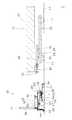
図1、図2に示すように、本発明の第1の実施の形態に係るアシスト自走台車10は、車輪付きの病院機器の一例であり、自在車輪11(車輪の一例)が設けられたベッド12の一部を載置してアシスト操作により平面床13上を移動するものである。ここで、アシスト自走台車10は、ベッド12の一部が一側に固定状態で載置される台車フレーム14と、台車フレーム14に力覚センサ15を介して設けられた、例えば、2つの球体駆動モジュール16、17とを有している。そして、図6、図7に示すように、それぞれの球体駆動モジュール16、17は、平面床13に上方から当接して回転する球体18と、球体18の上下方向中央位置を直交するXY方向から接する第1、第2の駆動車輪49、50と、第1、第2の駆動車輪49、50と反対側にあって第1、第2の駆動車輪49、50の反力を受ける第1の自在球軸受機構21と、球体18の上位置にあって球体18に掛かる荷重を受ける第2の自在球軸受機構22とを有している。Next, embodiments of the present invention will be described with reference to the accompanying drawings for understanding of the present invention.
As shown in FIGS. 1 and 2, the assist self-
更に、アシスト自走台車10は、それぞれの力覚センサ15によって検知されたアシスト操作のXY方向の力成分及びZ方向回りのモーメント量のいずれか一方又は双方によって、ベッド12のアシスト移動方向を求め、それぞれの球体駆動モジュール16、17をアシスト移動方向に移動させる制御手段(図示せず)と、力覚センサ15、球体駆動モジュール16、17及び制御手段等に電力を供給する電源(例えば、蓄電池、発電機)とを有している。ここで、XY方向は、例えば、水平面内で互いに直交する2方向、具体的には、台車フレームの前後方向及び幅方向とすることができる。また、Z方向は水平面(XY方向)に直交する方向とすることができる。なお、直交とは90度に対して±5%以内の誤差を有する場合も含む。Furthermore, the assist self-propelled
図1〜図4に示すように、ベッド12を移動する際に使用する自在車輪11はベッドフレーム23の前両側の下側及び後両側の下側にそれぞれ取付けられている(ここで、患者がベッド12を使用する際に頭部が配置される方向を前側(一側)、足部が配置される方向を後側(他側)とする)。そして、ベッド12の片側、例えば、ベッドフレーム23の後両側には、台車フレーム14の一側に先側を固定状態で載置される連結金具の一例である搬送用アタッチメント24、25が取付け部材26を介してそれぞれ取付けられている。なお、符号27は、ベッド12のマットレスである。以下、詳細に説明する。As shown in FIGS. 1 to 4, the
台車フレーム14の一側の幅方向両側には、搬送用アタッチメント24、25の先側(後側)に当接して台車フレーム14の位置調節を行って、搬送用アタッチメント24、25に対して台車フレーム14の位置決めを行う平面視して三角形状のガイド部材30と、搬送用アタッチメント24、25の先側に掛合する掛止部28(例えば、側面視してV字状の凹部)が形成され、上下方向に移動可能に設けられた受け金具29と、受け金具29を下方から搬送用アタッチメント24、25の先側に向けて上昇させ搬送用アタッチメント24、25の先側を受け金具29に載せて掛止部28に掛合させ、更に受け金具29を上昇させて、搬送用アタッチメント24、25の先側を持ち上げる昇降手段31がそれぞれ設けられている。ここで、受け金具29、ガイド部材30、及び昇降手段31は、台車フレーム14の幅方向両側にそれぞれ対称配置されている。また、昇降手段31は、受け金具29の下部の突出部32に当接する楔状部材33と、楔状部材33を載置する取付け台34を台車フレーム14の一側と他側の間で進退させる駆動機構35(例えば、流体圧シリンダ又は電動シリンダ、図3参照)と、取付け台34の移動を案内するレール部材36とを有している。On both sides in the width direction of one side of the
また、台車フレーム14の他側には、台車フレーム14の幅方向に長手方向を向けて棒状のハンドル部材37が柱部材38を介して設けられ、台車フレーム14の一側の幅方向両側の下側にはそれぞれ第1の自在車輪39が、台車フレーム14の他側の幅方向両側の下側にはそれぞれ昇降機構40(例えば、流体圧シリンダ又は電動シリンダ)を介して第2の自在車輪41が取付けられている。なお、球体駆動モジュール16、17は、台車フレーム14に取付けられた第1、第2の自在車輪39、41の間にそれぞれ取付けられている。昇降機構40を操作して、第2の自在車輪41の上下位置を調整することで、第1、第2の自在車輪39、41と共に球体駆動モジュール16、17の球体18を平面床13に確実に当接させることができる。Further, on the other side of the
搬送用アタッチメント24、25は、ベッドフレーム23の幅方向の両側にそれぞれ対称配置されており、基側がベッドフレーム23に取付け部材26を介して固定されるアタッチメント本体42と、アタッチメント本体42の先側の所定位置に軸方向をベッドフレーム23の幅方向に向けて取付けられ、受け金具29の掛止部28に両側が掛合する、例えば、ピン状の掛合部材43と、掛合部材43に対する受け金具29の位置決めを行うために、ガイド部材30を挿入させて台車フレーム14の位置調整を行う、例えば、平面視して先側にV字状の凹部44が形成された位置決め部材45とを有している。なお、ベッドフレーム23の幅方向両側に配置される位置決め部材45の凹部44同士の距離は、台車フレーム14の幅方向の両側に配置されるガイド部材30同士の距離に等しい。The
このような構成とすることにより、図3、図4に示すように、アシスト自走台車10をベッド12に向けて移動させて、ベッド12のベッドフレーム23の両側に取付けた搬送用アタッチメント24、25の位置決め部材45の凹部44に、台車フレーム14に設けたガイド部材30の先側を挿入すると、各ガイド部材30の先部が位置決め部材45の凹部44のV字状内周部の一方に当接する。そして、アシスト自走台車10を更にベッド12に向けて移動させると、各ガイド部材30の先部は、当接している凹部44のV字状内周部から押圧されるので、アシスト自走台車10は押圧方向に移動しながら凹部44内に進入する。その結果、各ガイド部材30の先部が凹部44の底部に当接した時点で、アシスト自走台車10の移動が停止し、台車フレーム14の幅方向の中心線と、ベッドフレーム23の幅方向の中心線の位置は一致する(ベッド12に対してアシスト自走台車10が位置決めされる)。ベッド12に対してアシスト自走台車10が位置決めされると、搬送用アタッチメント24、25に設けられた掛合部材43を、アシスト自走台車10に設けた受け金具29(掛止部28)の上方に位置させることができる。With such a configuration, as shown in FIGS. 3 and 4, the assisting self-propelled
そこで、図5に示すように、昇降手段31の駆動機構35を操作して、取付け台34をレール部材36に沿って台車フレーム14の一側(ベッド12側)に移動させると、楔状部材33の傾斜面46の下端部47に突出部32を介して載置されていた受け金具29を、傾斜面46に沿って押し上げることができる。これにより、搬送用アタッチメント24、25に設けられた掛合部材43を、受け金具29の掛止部28に掛合させることができる。そして、取付け台34を更に移動させると、受け金具29は掛合部材43を掛止部28に掛合させた状態で更に上昇し、突出部32が傾斜面46の上端部48に到達した時点で、搬送用アタッチメント24、25を介してベッドフレーム23の後側を平面床13から持ち上げることができる。その結果、ベッドフレーム23の後側に取付けられた自在車輪11を平面床13から浮かせることができる。なお、ベッドフレーム23は、2つの搬送用アタッチメント24、25を介して台車フレーム14に固定されるので、台車フレーム14とベッドフレーム23が平面床13上で移動する際、台車フレーム14の移動方向とベッドフレーム23(ベッド12)の移動方向は常に一致する。Therefore, as shown in FIG. 5, when the mounting
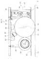
球体駆動モジュール16、17の球体18は、例えば、球状の芯材と、芯材を被覆して、平面床13に当接する表層部とを有している。ここで、芯材は、例えば、MCナイロン等の硬質プラスチックで形成され、表層部は、例えば、ウレタン等の硬質ゴムやポリアセタール樹脂で形成することができる。ここで、球体18の直径は100〜150mmの範囲であって、表層部の厚さは5〜15mmである。表層部が硬質ゴムやポリアセタール樹脂から形成されているので、平面床13との間でスリップが生じ難く、球体18の回転力で平面床13を確実に移動することができる。なお、球体は表層部なしの芯材で形成する場合も本発明は適用される。The
図6、図7に示すように、球体18の上下方向中央位置を、例えば、水平面内で直交するXY方向から接する第1、第2の駆動車輪49、50は、平面視して球体18の中心に向けて直交する方向から球体18に当接する。この第1、第2の駆動車輪49、50と、第1、第2の駆動車輪49、50をそれぞれ回転駆動する第1、第2の回転駆動源51、52を備えて第1、第2の駆動車輪機構19、20が構成される。ここで、第1、第2の駆動車輪49、50はそれぞれ、環状で球体18に当接する外周側が凸断面円弧状となって硬質ゴム(例えばウレタン)又は樹脂(例えばポリアセタール)から形成されている。また、第1、第2の回転駆動源51、52は、第1、第2の駆動車輪49、50の車軸部53に出力軸が接続するエンコーダ付きのパルスモータ54を有している。なお、エンコーダ付きのパルスモータ54の代わりに、エンコーダ付きのサーボモータを使用してもよい。As shown in FIGS. 6 and 7, the first and
図6、図7に示すように、球体駆動モジュール16、17の第1の自在球軸受機構21は、球体18の赤道の上部及び赤道の下部に、球体18の中心に向けてそれぞれ設けられた第1、第2の自在ボール支持部55、56と、第1、第2の自在ボール支持部55、56を保持して、球体18の中心に対して進退する位置調節機構57とを有している。また、第2の自在球軸受機構22は、球体18の頂部に配置される第3の自在ボール支持部58及び球体の上位置で第3の自在ボール支持部58の周囲に配置される少なくとも3つ(図6では、平面視して、第3の自在ボール支持部58を中心とした円周の周方向を3等分する位置にそれぞれ配置されている)の第4の自在ボール支持部59と、第3の自在ボール支持部58及び第4の自在ボール支持部59の各中心軸が球体18の中心を通るように第3の自在ボール支持部58及び第4の自在ボール支持部59を保持する取付け台60、61とを有している。As shown in FIGS. 6 and 7, the first free
第1の自在球軸受機構21の位置調節機構57により、球体18の赤道の上部及び赤道の下部に第1、第2の自在ボール支持部55、56を確実に当接させることができ、球体18と第1、第2の駆動車輪49、50との当接状態を維持することができると共に、第1、第2の駆動車輪49、50の反力を均等に受けることができる。これにより、球体18の回転制御を安定して行うことができる。また、第2の自在球軸受機構22が、球体18の頂部に配置される第3の自在ボール支持部58及び球体18の上位置で第3の自在ボール支持部58の周囲に配置される3つの第4の自在ボール支持部59を有するので、球体18に掛かる荷重をバランスよく受けることができると共に、球体18を所定位置に安定して保持することができる。By the
更に、球体駆動モジュール16、17は、第1、第2の駆動車輪機構19、20、第1、第2の自在球軸受機構21、22を取付ける基台62と、複数の支持部材63を介して基台62に取付けられて第1、第2の駆動車輪機構19、20、第1、第2の自在球軸受機構21、22を覆うと共に、下面に形成された開口部64から球体18の下部を露出させるカバー部材65とを有している。Furthermore, the spherical
図1に示すように、力覚センサ15は、例えば、球体駆動モジュール16、17の基台62と台車フレーム14との間で、球体駆動モジュール16、17の第3の自在ボール支持部58の直上位置に相当する場所に設けられ、力覚センサ15の上部は台車フレーム14に固定され、力覚センサ15の下部は基台62に固定されている。また、力覚センサ15は、互いに直交する3方向(X方向、Y方向、及びZ方向)の力成分の大きさをそれぞれ検知する機能を有している。ここで、X方向は、例えば、台車フレーム14の幅方向に平行であり、Y方向は台車フレーム14の幅方向に直交する方向、Z方向はX方向及びY方向に直交する方向である。この力覚センサ15は、Z方向回りのモーメント量を検知する機能を有している。また、力覚センサ15によって2つの球体18のZ方向の力成分を検知してそれぞれの球体18の撓みを求め、それぞれ球体18の回転数を変えて、アシスト自走台車10の蛇行を防止する。As shown in FIG. 1, the
ベッドフレーム23は、2つの搬送用アタッチメント24、25を介して台車フレーム14に固定されるので、台車フレーム14とベッドフレーム23が平面床13上で移動する際、台車フレーム14の移動方向とベッド12の移動方向は常に一致する。このため、アシスト操作を任意の場所(ハンドル部材37、台車フレーム14、及びベッド12における任意の場所)で行っても、台車フレーム14にはアシスト操作に伴う外力を伝達することができ、この外力を球体駆動モジュール16、17の球体18に伝達することができる。これにより、平面床13上を回転駆動している各球体18に作用するアシスト操作時のX方向の力成分、Y方向の力成分、及びZ方向回りのモーメント量が力覚センサ15により検知できる。また、力覚センサ15が、Z方向の力成分を検知する機能を備えているので、台車フレーム14に搬送用アタッチメント24、25を接続した際に、台車フレーム14に偏荷重が作用しているか否かが判定できる。更に、アシスト自走台車10の移動中に、球体駆動モジュール16、17の球体18に、偏荷重が作用しているか否かの判定もできる。Since the
力覚センサ15の出力(X、Y、及びZ方向の力成分、Z方向回りのモーメント量)に基づいて、球体駆動モジュール16、17の球体18をアシスト移動方向に移動させる制御手段は、力覚センサ15のX、Y方向の力成分に変化が存在しない場合に、球体駆動モジュール16、17の第1、第2の回転駆動源51、52に、アシスト走行台車10が予め設定された進行速度で現状の進行方向を維持して移動するための駆動信号を出力する機能(定常運転機能、停止する場合も含む)を有している。そして、制御手段は、台車フレーム14に偏荷重が作用して力覚センサ15のZ方向の力成分が異なる場合に、アシスト自走台車10が予め設定された進行速度で現状の進行方向を維持して移動するように、力覚センサ15でZ方向の力成分が大きく検知された球体18を備えた球体駆動モジュール16、17の球体18の回転速度を、力覚センサ15のZ方向の力成分が小さく検知された球体18を備えた球体駆動モジュール16、17の球体18の回転速度よりも速くする駆動信号を出力する機能(偏荷重補正機能)を有している。Based on the output of the force sensor 15 (force components in the X, Y and Z directions, moment amount around the Z direction), the control means for moving the
また、制御手段は、アシスト走行台車10の移動中に、力覚センサ15が球体駆動モジュール16、17の球体18に作用するX、Y方向の力成分の変化を検知した場合に、球体駆動モジュール16、17の第1、第2の回転駆動源51、52に、X、Y方向の力成分の合力方向に予め設定された進行速度で移動するための駆動信号を出力する機能(方向変化機能)を有している。そして、制御手段は、アシスト走行台車10が停止中に、力覚センサ15がZ方向回りのモーメント量を検知した場合に、球体駆動モジュール16、17の一方の球体駆動モジュールに対する他方の球体駆動モジュールのモーメント量偏差を求め、一方の球体駆動モジュールを固定し、他方の球体駆動モジュールの球体18がモーメント量偏差の回転方向に回転するように、他方の球体駆動モジュールの第1、第2の回転駆動源51、52に駆動信号を出力する機能(方向転換機能)を有している。Further, when the
更に、制御手段は、アシスト走行台車10が停止中にアシスト操作が行われて、力覚センサ15が球体駆動モジュール16、17の球体18に作用するX、Y方向の力成分の変化を検知した場合に、球体駆動モジュール16、17の第1、第2の回転駆動源51、52に、X、Y方向の力成分の合力方向に予め設定された進行速度で移動を開始するための駆動信号を出力する機能(発進機能)を有している。ここで、制御手段が、台車フレーム14に偏荷重が作用して力覚センサ15のZ方向の力成分が異なることを検知した場合は、
球体駆動モジュール16、17の第1、第2の回転駆動源51、52に、X、Y方向の力成分の合力方向に予め設定された進行速度で移動を開始するために求めた駆動信号を、力覚センサ15でZ方向の力成分が大きく検知された球体18を備えた球体駆動モジュール16、17の球体18の回転速度を、力覚センサ15のZ方向の力成分が小さく検知された球体18を備えた球体駆動モジュール16、17の球体18の回転速度よりも速くなるように補正する機能(発進補正機能)を有している。
なお、制御手段は、例えば、マイクロコンピュータに、発進機能、発進補正機能、定常運転機能、偏荷重補正機能、方向変化機能、及び方向転換機能を発現するプログラムを搭載させることにより構成することができる。Further, the control means detects the change in the force component in the X and Y directions that is applied to the
The drive signals obtained for starting the movement at the advance speed set in advance in the resultant direction of the force component in the X and Y directions are sent to the first and second
The control means can be configured, for example, by mounting a program that develops a start function, a start correction function, a steady operation function, an offset load correction function, a direction change function, and a direction change function on a microcomputer. .
続いて、本発明の第1の実施の形態に係るアシスト自走台車10の作用について、図8〜図10を用いて説明する。
図8、図9に示すように、アシスト自走台車10の台車フレーム14の下側には、第1の自在車輪39、昇降機構40を介して第2の自在車輪41、力覚センサ15を介して球体駆動モジュール16、17がそれぞれ設けられている。このため、搬送用アタッチメント24、25を介してベッド12の一部を台車フレーム14に載置した場合、昇降機構40を操作して第2の自在車輪41の上下方向位置を調節することで、平面床13に第1の自在車輪39、第2の自在車輪41、球体駆動モジュール16、17の球体18を確実に当接させることができる。そして、ベッドフレーム23に取付けた搬送用アタッチメント24、25の先側を台車フレーム14に固定状態で載置するので、台車フレーム14とベッド12が平面床13上で移動する際、台車フレーム14の移動方向とベッド12の移動方向は常に一致させることができ、アシスト自走台車10及びベッド12の任意の場所でアシスト操作を行っても、アシスト操作により球体18に作用するXYZ方向の力成分とZ方向回りのモーメント量を検知することができる。Then, the effect | action of the assist self-propelled
As shown in FIGS. 8 and 9, on the lower side of the
例えば、停止状態のアシスト自走台車10及びベッド12にアシスト操作が行われると、球体駆動モジュール16、17の球体18に作用するXY方向の力成分から、アシスト移動方向を求め、球体駆動モジュール16、17をアシスト移動方向に移動させる。これにより、アシスト方向にアシスト自走台車10を発進させることができる。ここで、図10に示すように、台車フレーム14に偏荷重が作用して、例えば、球体駆動モジュール16の球体18に作用するZ方向の力成分(鉛直方向の荷重)が、球体駆動モジュール17の球体18に作用するZ方向の力成分より大きな場合、球体駆動モジュール16の球体18の回転速度を、球体駆動モジュール17の球体18の回転速度よりも速くする。これにより、アシスト自走台車10がアシスト方向に予め設定された進行速度に向けてスムーズに加速することができる。For example, when the assist operation is performed on the assist self-propelled
また、アシスト自走台車10及びベッド12の移動中、アシスト操作により球体駆動モジュール16、17の球体18に作用するX、Y方向の力成分を力覚センサ15が検知した場合、球体駆動モジュール16、17を、XY方向の力成分の合力方向(アシスト移動方向)に予め設定された進行速度で移動させるので、アシスト自走台車10及びベッド12は、アシスト移動方向に進路を変える。なお、アシスト自走台車10及びベッド12の移動中、アシスト操作を行わないと、球体駆動モジュール16、17は、予め設定された進行速度で現状の進行方向を維持する。Further, when the
アシスト自走台車10及びベッド12の移動中において、図10に示すようにアシスト自走台車10に偏荷重が作用して、例えば、球体駆動モジュール16に作用するZ方向の力成分が、球体駆動モジュール17に作用するZ方向の力成分より大きくなった場合、球体駆動モジュール16の球体18は、球体駆動モジュール17の球体18と比較して、鉛直方向に大きく圧縮変形する。そこで、球体駆動モジュール16、17の球体18に作用するZ方向の力成分をそれぞれ力覚センサ15により検出し、球体駆動モジュール16、17の球体18に作用するZ方向の力成分に応じて、各球体駆動モジュール16、17の球体18の回転速度を調節する(Z方向の力成分の大きい球体18の回転速度を、Z方向の力成分の小さい球体18の回転速度より速くする)ことにより、台車フレーム14に偏荷重が作用しても、アシスト自走台車10を直進させることができる。During the movement of the assist self-propelled
更に、アシスト自走台車10及びベッド12が停止中に、アシスト操作により、力覚センサ15がZ方向回りのモーメント量を検知した場合、球体駆動モジュール16、17の一方の球体駆動モジュールに対する他方の球体駆動モジュールのモーメント量偏差を算出して、一方の球体駆動モジュールに対する他方の球体駆動モジュールのXY面内での回転方向を求め、一方の球体駆動モジュールを固定し、他方の球体駆動モジュールの球体18がモーメント量偏差の回転方向に回転するように、他方の球体駆動モジュールの第1、第2の回転駆動源51、52を操作するので、回転方向に他方の球体駆動モジュールが回転して、その場回転を行うことができる。そして、アシスト自走台車10及びベッド12のその場回転角度が、目的とする回転角度に近づくと、その場回転を停止させるアシスト操作(逆回転方向のアシスト操作)が行われるので、アシスト自走台車10及びベッド12のその場回転速度が徐々に低下して、目的とする回転角度だけ回転した時点で、アシスト自走台車10及びベッド12のその場回転は停止する。
なお、ベッド12の周囲に、例えば、呼吸器、点滴器等の付属医療機器が配置されている場合、台車フレーム14に付属医療機器を積載したり、アシスト操作を行う看護師がベッド12と共に付属医療機器を移動させることになる。Further, when the
For example, when an attached medical device such as a respirator or a dropper is disposed around the
本発明の第2の実施の形態に係るアシスト自走台車70は、図11、図12に示すように、本発明の第1の実施の形態に係るアシスト自走台車10と比較して、受け金具71と連結金具72の構成が異なっていること、受け金具71と連結金具72の構成が異なることにより、ベッド12に対するアシスト自走台車70の位置決めを行う構成、受け金具71に連結金具72を載せた状態で昇降する昇降手段の構成が異なっていること、アシスト自走台車70にアシスト操作を行う際のアシスト支援機器70aが設けられていることが特徴となっている。このため、特徴部分についてのみ説明し、第1の実施の形態に係るアシスト自走台車10と同一の構成部材については同一の符号を付して説明は省略する。As shown in FIG. 11 and FIG. 12, the assist self-propelled
図11(A)〜(C)、図12(A)、(B)に示すように、受け金具71は、例えば、角柱部材であって、先側の上部に凹状の掛止部73が形成されている。また、連結金具72は、先側に、受け金具71が挿入可能な収納部(図示せず)が形成された角柱部材であり、収納部の天井部には、掛止部73に嵌入可能な突起(図示せず)が設けられている。そして、受け金具71の基側は、それぞれ駆動機構を備えた昇降台(図示せず)に固定されている。As shown in FIGS. 11A to 11C and FIGS. 12A and 12B, the
アシスト自走台車70の台車フレーム14の一側の幅方向中央部には、例えば、2〜5mm径の赤色レーザ光束を放射するレーザ機器(図示せず)が取付けられており、赤色レーザ光束を台車フレーム14に取付けられたカバー部材74に形成された開口部75を介して一側空間に向けて放射することができる。従って、図13(A)に示すように、ベッド12の後側手摺り76の中央部に反射板77を取付け、反射板77の反射面上において、予め設定した高さ位置の部位に水平線78を、ベッド12の幅方向中央位置に相当する部位に赤色レーザ光束の径と同一の幅を有する垂直領域79、水平線78と垂直領域79の交わる交差領域80をそれぞれ形成しておくと、赤色レーザ光束を放射しながら台車フレーム14の一側をベッド12の後側に接近させる際に、赤色レーザ光束の赤光点81が垂直領域79内に存在するように台車フレーム14の位置を調節すると、ベッド12に対する台車フレーム14の位置決めが完了し、受け金具71を連結金具72の収納部に挿入することができる。ここで、台車フレーム14には、近接スイッチ(図示せず)が設けられ、近接スイッチからの信号によりランプ82が点灯することにより、受け金具71の連結金具72内への挿入終了が確認できる。A laser device (not shown) that emits a red laser beam with a diameter of 2 to 5 mm, for example, is attached to the central portion in the width direction on one side of the
受け金具71の連結金具72内への挿入が終了すると、図13(B)に示すように、台車フレーム14に設けたハンドル部材37に取付けた操作盤83の上昇スイッチ84を投入して駆動機構を駆動させ昇降台を上昇させることにより、収納部内で受け金具71を持ち上げることができ、受け金具71の掛止部73に、連結金具72の収納部に設けた突起を嵌入させて、受け金具71と連結金具72を掛合することができる。収納部内で受け金具71を所定の高さだけ持ち上げると、受け金具71の掛止部73に連結金具72の収納部に設けた突起は必ず嵌入するので、受け金具71が所定の高さ上昇したことを検知して、操作盤83の合体ランプ85を点灯する。When the insertion of the receiving
そして、昇降台を更に上昇させると、受け金具71は連結金具72を掛合させた状態で更に上昇し、図14(B)に示すように、連結金具72を介してベッド12の後側を平面床13から持ち上げることができる。昇降台が上昇してベッド12の後側が平面床13から持ち上げられた場合、反射板77はベッド12と共に上昇するので、垂直領域79内に存在する赤光点81は下降する。このため、図13(A)、(B)に示すように、赤光点81が水平線78の高さ位置まで下降した時点で、昇降台の上昇を停止すると、操作盤83のOKランプ86を点灯して、ベッド12の後側に設けられた自在車輪11を平面床13から所定の高さだけ浮かせることができる。ここで、昇降台を上昇させ過ぎた場合は、操作盤83の下降スイッチ87を投入して、OKランプ86が点灯するまで昇降台を下降させる。なお、符号88、89は電源の投入スイッチ、遮断スイッチ、符号90、91は、レーザ機器の可動スイッチ、停止スイッチである。When the lifting platform is further raised, the receiving
アシスト支援機器70aは、台車フレーム14の他側の両側に立接された柱部材38により所定高さ位置に配置されたハンドル部材37(支持部材の一例)の両側にそれぞれ設けられた凸面ミラー92、93と、台車フレーム14の他側の両側に配置されて、台車フレーム14の他側の周囲に存在する障害物を検知するセンサ(図示せず)と、センサからの信号により障害物までの距離を検知する距離計(図示せず)と、障害物までの検知距離に応じて異なる色のランプを点灯する点灯器94とを有している。このような構成とすることにより、凸面ミラー92、93により、アシスト自走台車70の他側の周囲360度の範囲の状況を確認することができ、アシスト操作を的確に行うことができる。また、障害物の検知距離に応じて異なる色のランプが点灯するので、アシスト操作のタイミングを容易に計ることができる。The
本発明の第2の実施の形態に係るアシスト自走台車70の作用において、アシスト操作に基づくアシスト自走台車70の応答は、アシスト自走台車10の応答と同一なので、説明は省略し、アシスト支援機器70aを設けたことによる作用について説明する。
図14(A)に示すように、凸面ミラー92、93により、アシスト自走台車70の他側の周囲360度の範囲の状況を確認することができるので、また、台車フレーム14の他側の周囲に存在する障害物をセンサで検知して、障害物までの検知距離に応じて異なる色のランプが点灯するので、図14(B)に示すように、ベッド12の前側の手摺り95からアシスト操作を行うことができ、アシスト操作と患者の状況確認を同時に行うことができる。In the operation of the assist self-propelled
As shown in FIG. 14A, the
以上、本発明を、実施の形態を参照して説明してきたが、本発明は何ら上記した実施の形態に記載した構成に限定されるものではなく、特許請求の範囲に記載されている事項の範囲内で考えられるその他の実施の形態や変形例も含むものである。
更に、本実施の形態とその他の実施の形態や変形例にそれぞれ含まれる構成要素を組合わせたものも、本発明に含まれる。
例えば、本実施の形態では、病院機器をベッドとしたが、車椅子、配膳台、医療機器、移乗器、歩行器、(立位)移動器のいずれか1とすることもできる。また、アシスト自走台車に病院機器の全部を載置してもよい。
球体駆動モジュールを2つ設ける場合、球体駆動モジュールを台車フレームの幅方向の一方側に2つ並べて配置してもよい。また、球体駆動モジュールを3つ設ける場合は、台車フレームの幅方向の一方側に2つ並べて配置し、他方側に1つ配置することになる。更に、球体駆動モジュールを4つ設ける場合は、台車フレームの幅方向の両側にそれぞれ2つ並べて配置する。なお、球体駆動モジュールを5つ以上設ける場合は、台車フレームの幅方向の両側にそれぞれ1つ以上配置することになるが、球体駆動モジュールの個数を増やしてもアシスト操作性に大きな違いは生じないので、経済性の観点からは、台車フレームに設ける球体駆動モジュールの最大数は4である。
本実施の形態では、ベッド(病院機器)に連結金具を設け、アシスト自走台車に連結金具に掛合する受け金具をそれぞれ設けたが、ベッド(病院機器)の構成部材の一部に掛合する受け金具をアシスト自走台車に設けてもよい。
配膳台や移乗器等では、車輪を取り除いて、本体部分をアシスト自走台車の台車フレームに直接載置して固定することもできる。As described above, the present invention has been described with reference to the embodiment. However, the present invention is not limited to the configuration described in the above-described embodiment, and the matters described in the scope of claims. Other embodiments and modifications conceivable within the scope are also included.
Further, the present invention also includes a combination of components included in the present embodiment and other embodiments and modifications.
For example, in the present embodiment, the hospital equipment is a bed, but it may be any one of a wheelchair, a podium, a medical equipment, a transfer device, a walker, and a (standing position) mobile device. Moreover, you may mount all the hospital equipment on an assist self-propelled cart.
When two sphere driving modules are provided, two sphere driving modules may be arranged side by side on one side in the width direction of the carriage frame. When three spherical body drive modules are provided, two are arranged side by side on one side in the width direction of the carriage frame, and one is arranged on the other side. Furthermore, when four spherical body drive modules are provided, two are arranged side by side on both sides in the width direction of the carriage frame. When five or more sphere driving modules are provided, one or more are arranged on both sides in the width direction of the carriage frame. However, even if the number of sphere driving modules is increased, there is no significant difference in assist operability. Therefore, from the viewpoint of economy, the maximum number of spherical drive modules provided on the carriage frame is four.
In the present embodiment, a connecting bracket is provided on the bed (hospital equipment), and a receiving bracket that engages with the connecting bracket is provided on the assist self-propelled carriage. However, the receiving hook that is engaged with a part of the components of the bed (hospital equipment) is provided. A bracket may be provided on the assist self-propelled carriage.
In a table, a transfer device, or the like, the wheels can be removed and the main body portion can be directly placed and fixed on the cart frame of the assisting self-propelled cart.
10:アシスト自走台車、11:自在車輪、12:ベッド、13:平面床、14:台車フレーム、15:力覚センサ、16、17:球体駆動モジュール、18:球体、19:第1の駆動車輪機構、20:第2の駆動車輪機構、21:第1の自在球軸受機構、22:第2の自在球軸受機構、23:ベッドフレーム、24、25:搬送用アタッチメント、26:取付け部材、27:マットレス、28:掛止部、29:受け金具、30:ガイド部材、31:昇降手段、32:突出部、33:楔状部材、34:取付け台、35:駆動機構、36:レール部材、37:ハンドル部材、38:柱部材、39:第1の自在車輪、40:昇降機構、41:第2の自在車輪、42:アタッチメント本体、43:掛合部材、44:凹部、45:位置決め部材、46:傾斜面、47:下端部、48:上端部、49:第1の駆動車輪、50:第2の駆動車輪、51:第1の回転駆動源、52:第2の回転駆動源、53:車軸部、54:パルスモータ、55:第1の自在ボール支持部、56:第2の自在ボール支持部、57:位置調節機構、58:第3の自在ボール支持部、59:第4の自在ボール支持部、60、61:取付け台、62:基台、63:支持部材、64:開口部、65:カバー部材、70:アシスト自走台車、70a:アシスト支援機器、71:受け金具、72:連結金具、73:掛止部、74:カバー部材、75:開口部、76:後側手摺り、77:反射板、78:水平線、79:垂直領域、80:交差領域、81:赤光点、82:ランプ、83:操作盤、84:上昇スイッチ、85:合体ランプ、86:OKランプ、87:下降スイッチ、88:投入スイッチ、89:遮断スイッチ、90:可動スイッチ、91:停止スイッチ、92、93:凸面ミラー、94:点灯器、95:手摺り10: Assisted self-propelled cart, 11: Swivel wheel, 12: Bed, 13: Plane floor, 14: Cart frame, 15: Force sensor, 16, 17: Spherical drive module, 18: Spherical, 19: First drive Wheel mechanism, 20: second drive wheel mechanism, 21: first universal ball bearing mechanism, 22: second universal ball bearing mechanism, 23: bed frame, 24, 25: attachment for conveyance, 26: attachment member, 27: Mattress, 28: Latching part, 29: Bracket, 30: Guide member, 31: Lifting means, 32: Projection part, 33: Wedge-shaped member, 34: Mounting base, 35: Drive mechanism, 36: Rail member, 37: Handle member, 38: Column member, 39: First universal wheel, 40: Lifting mechanism, 41: Second universal wheel, 42: Attachment main body, 43: Engagement member, 44: Recess, 45: Positioning member, 46 Inclined surface, 47: lower end, 48: upper end, 49: first drive wheel, 50: second drive wheel, 51: first rotation drive source, 52: second rotation drive source, 53: axle , 54: pulse motor, 55: first free ball support, 56: second free ball support, 57: position adjustment mechanism, 58: third free ball support, 59: fourth free ball Support part, 60, 61: Mounting base, 62: Base, 63: Support member, 64: Opening part, 65: Cover member, 70: Assist self-propelled carriage, 70a: Assist support equipment, 71: Receiving bracket, 72: Connecting bracket, 73: latching portion, 74: cover member, 75: opening, 76: rear handrail, 77: reflector, 78: horizontal line, 79: vertical region, 80: intersection region, 81: red spot , 82: lamp, 83: operation panel, 84: lift switch, 85: coalescence Flop, 86: OK lamp, 87: lowering switch, 88: start switch, 89: cut-off switch, 90: movable switch, 91: stop switch, 92, 93: convex mirror, 94: ignitor, 95: handrail
Claims (7)
Translated fromJapanese前記病院機器の一部又は全部を、一側に固定状態で載置する台車フレームと、該台車フレームに力覚センサを介して設けられた少なくとも2つの球体駆動モジュールとを有し、
それぞれの前記球体駆動モジュールは、球体と、該球体の上下方向中央位置を直交するXY方向から接する第1、第2の駆動車輪と、該第1、第2の駆動車輪とそれぞれ反対側にあって該第1、第2の駆動車輪の反力を受ける第1の自在球軸受機構と、前記球体の上位置にあって前記球体に掛かる荷重を受ける第2の自在球軸受機構とを有し、
更に、それぞれの前記力覚センサによって、前記病院機器のアシスト操作のXY方向の力成分とZ方向回りのモーメント量を検知し、前記XY方向の力成分及び前記Z方向回りのモーメント量のいずれか一方又は双方によって、前記病院機器のアシスト移動方向を求め、それぞれの前記球体駆動モジュールをアシスト移動方向に移動させる制御手段が設けられていることをアシスト自走台車。Assist itself to move a part of or all of the wheeled hospital equipment consisting of any one of bed, wheelchair, table, medical equipment, transfer device, walker, and mobile device on the flat floor by the assist operation A carriage,
A carriage frame for mounting a part or all of the hospital equipment in a fixed state on one side, and at least two sphere drive modules provided on the carriage frame via force sensors,
Each of the sphere drive modules has a sphere, first and second drive wheels that are in contact with each other from the XY directions perpendicular to the vertical center position of the sphere, and opposite to the first and second drive wheels. A first free ball bearing mechanism that receives the reaction force of the first and second drive wheels, and a second free ball bearing mechanism that is located above the sphere and receives a load applied to the sphere. ,
Furthermore, the force sensor in the XY direction and the moment amount around the Z direction of the assist operation of the hospital device are detected by each of the force sensors, and either the force component in the XY direction or the moment amount around the Z direction is detected. The assist self-propelled carriage is provided with a control means for obtaining the assist movement direction of the hospital equipment by one or both and moving each of the spherical drive modules in the assist movement direction.
Priority Applications (1)
| Application Number | Priority Date | Filing Date | Title |
|---|---|---|---|
| JP2013256407AJP2015112290A (en) | 2013-12-11 | 2013-12-11 | Assisted self-propelled carriage |
Applications Claiming Priority (1)
| Application Number | Priority Date | Filing Date | Title |
|---|---|---|---|
| JP2013256407AJP2015112290A (en) | 2013-12-11 | 2013-12-11 | Assisted self-propelled carriage |
Publications (1)
| Publication Number | Publication Date |
|---|---|
| JP2015112290Atrue JP2015112290A (en) | 2015-06-22 |
Family
ID=53526667
Family Applications (1)
| Application Number | Title | Priority Date | Filing Date |
|---|---|---|---|
| JP2013256407APendingJP2015112290A (en) | 2013-12-11 | 2013-12-11 | Assisted self-propelled carriage |
Country Status (1)
| Country | Link |
|---|---|
| JP (1) | JP2015112290A (en) |
Cited By (6)
| Publication number | Priority date | Publication date | Assignee | Title |
|---|---|---|---|---|
| CN114191213A (en)* | 2021-10-26 | 2022-03-18 | 深圳市爱博医疗机器人有限公司 | Mobile trolley |
| US20220388560A1 (en)* | 2021-06-04 | 2022-12-08 | Koyo Machine Industries Co., Ltd. | Transport assist equipment and bed |
| WO2023145098A1 (en)* | 2022-01-28 | 2023-08-03 | リーフ株式会社 | Conveyance assistance device |
| KR20240059387A (en)* | 2022-10-27 | 2024-05-07 | 충남대학교병원 | transfer apparatus for patient bed |
| JP7526345B1 (en) | 2023-12-25 | 2024-07-31 | 株式会社イトーキ | Nursing care facilities |
| WO2024181384A1 (en)* | 2023-02-27 | 2024-09-06 | 大成建設株式会社 | Conveyance assistance device |
- 2013
- 2013-12-11JPJP2013256407Apatent/JP2015112290A/enactivePending
Cited By (12)
| Publication number | Priority date | Publication date | Assignee | Title |
|---|---|---|---|---|
| US20220388560A1 (en)* | 2021-06-04 | 2022-12-08 | Koyo Machine Industries Co., Ltd. | Transport assist equipment and bed |
| JP2022186415A (en)* | 2021-06-04 | 2022-12-15 | 株式会社ジェイテクトマシンシステム | Transport aids and medical beds |
| JP7570286B2 (en) | 2021-06-04 | 2024-10-21 | 株式会社ジェイテクトマシンシステム | Transport aids and medical beds |
| CN114191213A (en)* | 2021-10-26 | 2022-03-18 | 深圳市爱博医疗机器人有限公司 | Mobile trolley |
| CN114191213B (en)* | 2021-10-26 | 2023-10-13 | 深圳市爱博医疗机器人有限公司 | A travelling car for with catheter bed body butt joint |
| WO2023145098A1 (en)* | 2022-01-28 | 2023-08-03 | リーフ株式会社 | Conveyance assistance device |
| JP2023110649A (en)* | 2022-01-28 | 2023-08-09 | リーフ株式会社 | Transport assist device |
| KR20240059387A (en)* | 2022-10-27 | 2024-05-07 | 충남대학교병원 | transfer apparatus for patient bed |
| KR102850064B1 (en)* | 2022-10-27 | 2025-08-22 | 충남대학교병원 | transfer apparatus for patient bed |
| WO2024181384A1 (en)* | 2023-02-27 | 2024-09-06 | 大成建設株式会社 | Conveyance assistance device |
| JP7526345B1 (en) | 2023-12-25 | 2024-07-31 | 株式会社イトーキ | Nursing care facilities |
| JP2025101200A (en)* | 2023-12-25 | 2025-07-07 | 株式会社イトーキ | Nursing care facilities |
Similar Documents
| Publication | Publication Date | Title |
|---|---|---|
| JP2015112290A (en) | Assisted self-propelled carriage | |
| AU2019202383B2 (en) | Methods and systems for automatically articulating cots | |
| US20230238837A1 (en) | Power transfer system with patient transport apparatus and power transfer device to transfer power to the patient transport apparatus | |
| JP6417044B2 (en) | Powered ambulance cot with automated cot control system | |
| JP7053522B2 (en) | Robot fixing devices, robots and robot systems | |
| US20220320916A1 (en) | Power Transfer System With Patient Support Apparatus And Power Transfer Device To Transfer Power To The Patient Support Apparatus | |
| JP2012040935A (en) | Battery replacement device of electric vehicle | |
| JP2019059618A (en) | Carrier transport robot | |
| JP7324628B2 (en) | Work platform mover system | |
| JP2011025819A (en) | Battery changer for vehicle | |
| JP6535182B2 (en) | Bogie device and work system | |
| US11701920B2 (en) | Driving wheel, carriage, and apparatus | |
| US10406857B2 (en) | Alignment system and method for wheel assembly | |
| JP5862986B2 (en) | Automated guided vehicle | |
| KR20130098484A (en) | A coil alignment device | |
| JP7365619B2 (en) | Trolleys and vehicles | |
| JP5485082B2 (en) | Electric wheelchair autopilot system | |
| JP6459927B2 (en) | Transport assist device | |
| JP2019099063A (en) | Heavy cargo carrying carriage | |
| CN113023633B (en) | Portable electric power construction elevating platform | |
| CN115400966B (en) | Automatic appearance detection equipment for motor products | |
| JP6669049B2 (en) | Carrier | |
| JP2023110649A (en) | Transport assist device | |
| JP2022136657A (en) | Self-traveling carriage for installation | |
| WO2021090341A1 (en) | Universal mechanical floor device that automatically adapts the position of its components for the precision parking of electric mobility devices with wheels, to automatically align, at the correct distance, the plate, for inductive charging, housed by the device and the plate fixed at on the lower side of the devices themselves |