JP2015104253A - Wireless power supply system - Google Patents
Wireless power supply systemDownload PDFInfo
- Publication number
- JP2015104253A JP2015104253AJP2013244109AJP2013244109AJP2015104253AJP 2015104253 AJP2015104253 AJP 2015104253AJP 2013244109 AJP2013244109 AJP 2013244109AJP 2013244109 AJP2013244109 AJP 2013244109AJP 2015104253 AJP2015104253 AJP 2015104253A
- Authority
- JP
- Japan
- Prior art keywords
- power
- vehicle
- side coil
- electronic key
- portable device
- Prior art date
- Legal status (The legal status is an assumption and is not a legal conclusion. Google has not performed a legal analysis and makes no representation as to the accuracy of the status listed.)
- Abandoned
Links
- 230000005540biological transmissionEffects0.000claimsabstractdescription85
- 238000004891communicationMethods0.000claimsabstractdescription69
- 230000004308accommodationEffects0.000claims1
- 238000000034methodMethods0.000description12
- 238000001514detection methodMethods0.000description10
- 230000004048modificationEffects0.000description8
- 238000012986modificationMethods0.000description8
- 230000008569processEffects0.000description6
- 238000010586diagramMethods0.000description4
- 230000005611electricityEffects0.000description4
- 230000005674electromagnetic inductionEffects0.000description3
- 230000006870functionEffects0.000description3
- 238000012423maintenanceMethods0.000description3
- 230000001413cellular effectEffects0.000description2
- 239000004020conductorSubstances0.000description2
- 230000000694effectsEffects0.000description2
- 230000005672electromagnetic fieldEffects0.000description2
- 238000009774resonance methodMethods0.000description2
- 230000001133accelerationEffects0.000description1
- 239000000470constituentSubstances0.000description1
- 230000004907fluxEffects0.000description1
- 230000006872improvementEffects0.000description1
- 230000007246mechanismEffects0.000description1
- 230000009467reductionEffects0.000description1
- 239000007858starting materialSubstances0.000description1
- 238000012795verificationMethods0.000description1
Images


Landscapes
- Charge And Discharge Circuits For Batteries Or The Like (AREA)
Abstract
Description
Translated fromJapanese本発明は、ワイヤレス給電システムに関する。 The present invention relates to a wireless power feeding system.
従来のワイヤレス給電システムとして、例えば、特許文献1には、1次コイルに交流電流が供給されることで被充電装置に非接触で送電する非接触充電装置が開示されている。この非接触充電装置は、電子キー及び車載装置間の無線通信時に車載装置のアンテナへの交流電流の供給を検出したときに1次コイルに供給される交流電流を抑制する。 As a conventional wireless power supply system, for example,
ところで、上述の特許文献1に記載の非接触充電装置は、上記構成により、当該非接触充電装置において、電子キーシステムの通信に対する電波干渉を抑制しているが、例えば、上記電子キー等の携帯機の充電の点で更なる改善の余地がある。 By the way, the non-contact charging device described in
本発明は、上記の事情に鑑みてなされたものであって、適正に携帯機を充電することができるワイヤレス給電システムを提供することを目的とする。 The present invention has been made in view of the above circumstances, and an object thereof is to provide a wireless power feeding system that can appropriately charge a portable device.
上記目的を達成するために、本発明に係るワイヤレス給電システムは、受電側コイルで受電した電力を蓄電装置に蓄電すると共に当該蓄電装置に蓄電された電力によって作動する携帯機と車両の内部で通信し前記蓄電装置の蓄電量に関する情報を取得する車両側通信部と、前記車両に設けられた電源からの電力を前記受電側コイルに伝送する送電側コイルと、前記車両の内部で前記送電側コイルから前記受電側コイルへの電力の伝送が可能な状態で、前記車両側通信部によって取得された前記蓄電装置の蓄電量に基づいて、前記送電側コイルから前記受電側コイルへ電力を伝送する制御を実行する制御部とを備えることを特徴とする。 In order to achieve the above object, a wireless power feeding system according to the present invention stores electric power received by a power receiving coil in a power storage device and communicates between a portable device operated by the power stored in the power storage device and the inside of the vehicle. A vehicle-side communication unit that acquires information about the amount of power stored in the power storage device, a power-transmission-side coil that transmits power from a power source provided in the vehicle to the power-receiving-side coil, and the power-transmission-side coil inside the vehicle. Control for transmitting power from the power transmission side coil to the power reception side coil based on the amount of power stored in the power storage device acquired by the vehicle side communication unit in a state where power can be transmitted from the power transmission side to the power reception side coil And a control unit for executing the above.
また、上記ワイヤレス給電システムでは、前記携帯機を、前記送電側コイルから前記受電側コイルへの電力の伝送が可能な位置に保持する保持部と、前記携帯機の前記保持部への保持を促す旨の案内情報を出力する案内装置とを備え、前記制御部は、前記車両側通信部によって取得された前記蓄電装置の蓄電量が予め設定される許容下限値以下である場合に、前記案内装置を制御し前記案内情報を出力させるものとすることができる。 In the wireless power supply system, the portable device is held in a position where power can be transmitted from the power transmission side coil to the power reception side coil, and the portable device is urged to be held in the holding unit. A guidance device that outputs guidance information to the effect, and wherein the control unit is configured such that when the amount of power stored in the power storage device acquired by the vehicle-side communication unit is equal to or less than a preset allowable lower limit value. And the guidance information can be output.
また、上記ワイヤレス給電システムでは、前記携帯機は、固有に保持する識別情報を送信して前記車両に少なくとも1つ以上の動作を実行させる電子キーであるものとすることができる。 In the wireless power supply system, the portable device may be an electronic key that transmits identification information that is uniquely held to cause the vehicle to perform at least one operation.
また、上記ワイヤレス給電システムでは、前記保持部は、前記電子キーが挿入されるキー穴部を含んで構成され、前記送電側コイルは、前記電子キーが前記キー穴部に挿入された状態で、前記受電側コイルと対向する位置に設けられるものとすることができる。 In the wireless power feeding system, the holding unit is configured to include a key hole portion into which the electronic key is inserted, and the power transmission side coil is in a state where the electronic key is inserted into the key hole portion. It can be provided at a position facing the power receiving coil.
また、上記ワイヤレス給電システムでは、前記保持部は、前記電子キーを収容する収容部を含んで構成され、前記送電側コイルは、前記電子キーが前記収容部に収容された状態で、前記受電側コイルと対向する位置に設けられるものとすることができる。 Further, in the wireless power feeding system, the holding unit is configured to include a storage unit that stores the electronic key, and the power transmission side coil is configured such that the electronic key is stored in the storage unit, It can be provided at a position facing the coil.
また、上記ワイヤレス給電システムでは、前記携帯機と前記車両側通信部とによる通信可能範囲は、当該携帯機が前記車両の車内にある状態で少なくとも当該車両の室内を含むものとすることができる。 In the wireless power feeding system, the communicable range between the portable device and the vehicle-side communication unit may include at least the interior of the vehicle when the portable device is in the vehicle.
本発明に係るワイヤレス給電システムは、制御部が車両側通信部によって取得された携帯機の蓄電装置の蓄電量に基づいて、送電側コイルから当該携帯機の受電側コイルへ電力を伝送する制御を実行し、当該蓄電装置を充電するので、適正に携帯機を充電することができる、という効果を奏する。 In the wireless power supply system according to the present invention, the control unit performs control to transmit power from the power transmission side coil to the power reception side coil of the portable device based on the amount of power stored in the power storage device of the portable device acquired by the vehicle side communication unit. Since it performs and charges the said electrical storage apparatus, there exists an effect that a portable machine can be charged appropriately.
以下に、本発明に係る実施形態を図面に基づいて詳細に説明する。なお、この実施形態によりこの発明が限定されるものではない。また、下記実施形態における構成要素には、当業者が置換可能かつ容易なもの、あるいは実質的に同一のものが含まれる。 Embodiments according to the present invention will be described below in detail with reference to the drawings. In addition, this invention is not limited by this embodiment. In addition, constituent elements in the following embodiments include those that can be easily replaced by those skilled in the art or those that are substantially the same.
[実施形態]
図1は、実施形態に係るワイヤレス給電システムの概略構成を表す模式的な構成図である。図2は、実施形態に係るワイヤレス給電システムの保持部の一例を表す模式的な部分斜視図である。図3は、実施形態に係るワイヤレス給電システムの保持部の一例を表す模式的な断面図である。図4は、実施形態に係るワイヤレス給電システムにおける制御の一例を表すフローチャートである。[Embodiment]
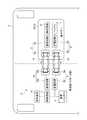
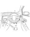
FIG. 1 is a schematic configuration diagram illustrating a schematic configuration of a wireless power feeding system according to an embodiment. FIG. 2 is a schematic partial perspective view illustrating an example of a holding unit of the wireless power feeding system according to the embodiment. FIG. 3 is a schematic cross-sectional view illustrating an example of a holding unit of the wireless power feeding system according to the embodiment. FIG. 4 is a flowchart illustrating an example of control in the wireless power feeding system according to the embodiment.
図1に示す本実施形態に係るワイヤレス給電システム1は、電源4からの電力を種々の機器に伝送する際に、少なくとも一部分をワイヤレスで伝送する非接触給電システムである。本実施形態のワイヤレス給電システム1は、車両2に搭載され、当該車両2の車内に持ち込まれる携帯機3側と車両2側との間の電気的な接続の一部をワイヤレス化し、非接触電力伝送とするものである。さらに言えば、本実施形態のワイヤレス給電システム1は、携帯機3に非接触充電可能な機能を持たせ、車両2の使用中に当該携帯機3を充電可能とすることで、当該携帯機3の電池交換を極力不要とするシステムである。 A wireless
ここで、このワイヤレス給電システム1によって充電される携帯機3は、ワイヤレス給電システム1から供給される電力を蓄電すると共に当該蓄電した電力によって作動するものである。より詳細には、携帯機3は、後述する受電側コイル6aで受電した電力を蓄電装置としてのバッテリ7に蓄電すると共に当該バッテリ7に蓄電された電力によって作動する。当該携帯機3としては、例えば、ノートパソコン、携帯ゲーム機、携帯電話、タブレット端末等の種々の携帯端末機器や電子キー等を含んでもよい。 Here, the
本実施形態の携帯機3は、無線通信機能を有し、固有に保持する識別情報(認証情報、認証コード)を送信して車両2に少なくとも1つ以上の動作を実行させる電子キー3Aであるものとして説明する(以下、携帯機3を単に「電子キー3A」という場合がある。)。この電子キー3Aは、例えば、車両2の所定の部位を遠隔操作できるようにしたキーレスエントリシステムの一部を構成するものである。当該キーレスエントリシステムは、車両2の車載器と電子キー3Aとの交信データに基づいて、該電子キー3Aに割り当てられた固有の識別情報と、車載器側のメモリに予め登録された識別情報とを照査し、この照査結果に応じて車両2の各部を自動で作動させるシステムである。電子キー3Aは、例えば、操作に応じてロック・アンロック信号を車両2の車載器側に送信し、車両2のドア、トランク等のロック・アンロック機構を自動で駆動することにより、当該ドア、トランク等のロック・アンロック状態を遠隔操作するものである。 The
具体的には、ワイヤレス給電システム1は、図1に示すように、電源4と、送電部5と、受電部6と、バッテリ7と、検出回路8と、携帯機側通信部9と、車両側通信部10と、制御部としての制御回路11とを備える。 Specifically, as shown in FIG. 1, the wireless
電源4は、車両2に搭載されるものであり、例えば、バッテリ等の蓄電装置によって構成される。送電部5は、車両2側に設けられ、送電側コイル(1次側コイル)5aと、送電回路5bとを含んで構成される。受電部6は、電子キー3A側に内蔵され、受電側コイル(2次側コイル)6aと、受電回路6bとを含んで構成される。送電側コイル5aは、種々のケーブル、コネクタ、送電回路5b等を介して電源4と電気的に接続される。送電回路5bは、インバータ等を含んで構成される。送電側コイル5aは、電源4からの電力がこれら種々のケーブル、コネクタ、送電回路5b等を介して供給される。送電側コイル5aは、電源4からの電力を受電側コイル6aに伝送する。受電側コイル6aは、送電側コイル5aからの電力を非接触で受電するものである。受電回路6bは、整流器等を含んで構成される。 The power source 4 is mounted on the vehicle 2 and is configured by a power storage device such as a battery. The power transmission unit 5 is provided on the vehicle 2 side, and includes a power transmission side coil (primary side coil) 5a and a
一対の送電側コイル5aと受電側コイル6aとは、例えば、ともに渦巻き状に巻かれた導体コイルによって構成され、軸方向に互いに対向することで、1組の非接触給電用トランス12を構成する。非接触給電用トランス12は、例えば、電磁誘導方式、電磁界共鳴方式等、種々の方式によって送電側コイル5aから受電側コイル6aに非接触で電力を伝送することができる。ここで、電磁誘導方式とは、送電側コイル5aに交流電流を流すことで発生する磁束を媒体として受電側コイル6aに起電力を発生させる電磁誘導を用いて送電側コイル5aから受電側コイル6aに電力を伝送する方式である。また、電磁界共鳴方式とは、送電側コイル5aに交流電流を流すことで送電側コイル5aと受電側コイル6aとを特定の周波数で共鳴させ、当該電磁界の共鳴現象を用いて送電側コイル5aから受電側コイル6aに電力を伝送する方式である。 The pair of power
より詳細には、非接触給電用トランス12は、送電側コイル5aから受電側コイル6aに電力を伝送する場合、送電側コイル5aと受電側コイル6aとが軸方向に互いに間隔をあけて対向した状態で、電源4からの直流電流が送電回路5b等を介して、任意の周波数の交流電流に変換されて送電側コイル5aに供給される。非接触給電用トランス12は、送電側コイル5aに交流電流が供給されると、例えば、送電側コイル5aと受電側コイル6aとが電磁誘導結合し、送電側コイル5aからの電力が電磁誘導や電磁界共鳴により非接触で受電側コイル6aに受電される。受電側コイル6aが受電した電力は、受電回路6b等を介して、交流電流から直流電流に変換されて電子キー3Aで利用される。 More specifically, when the non-contact
バッテリ7は、電子キー3A側に内蔵される。バッテリ7は、電力を蓄電可能な二次電池である。バッテリ7は、受電回路6bに電気的に接続され、受電側コイル6aで受電し受電回路6bを介して供給される電力によって充電され、当該電力を蓄電する。バッテリ7に蓄電された電力は、電子キー3Aを作動させるために利用される。検出回路8は、バッテリ7の蓄電量を検出する回路である。 The battery 7 is built in the electronic key 3A side. The battery 7 is a secondary battery capable of storing electric power. The battery 7 is electrically connected to the
携帯機側通信部9は、電子キー3A側に内蔵され、携帯機側アンテナ9aと、通信回路9bとを含んで構成される。車両側通信部10は、車両2側に設けられ、車両側アンテナ10aと、通信回路10bとを含んで構成される。一対の携帯機側アンテナ9aと車両側アンテナ10aとは、例えば、ともに渦巻き状に巻かれた導体コイルによって構成される。携帯機側通信部9の通信回路9bは、携帯機側アンテナ9aと検出回路8とに電気的に接続されている。車両側通信部10の通信回路10bは、車両側アンテナ10aと制御回路11に電気的に接続されている。携帯機側通信部9と車両側通信部10とは、1組の通信部13を構成する。通信部13は、例えば、NFC(Near Field Communication)、Bluetooth(登録商標)、Wi−Fi(Wireless Fidelity)、ZigBee(登録商標)等、種々のワイヤレス通信方式によって携帯機側通信部9と車両側通信部10との間で通信を行い、相互に検出信号や制御指令等の情報を授受することができる。電子キー3Aと車両側通信部10とによる通信可能範囲、すなわち、通信部13における通信可能範囲は、送電側コイル5aと受電側コイル6aとの電力伝送可能範囲より広い。より詳細には、電子キー3Aと車両側通信部10とによる通信可能範囲は、電子キー3Aが車両2の車内にある状態で少なくとも当該車両2の室内の全域を含む。 The portable device
本実施形態の携帯機側通信部9は、検出回路8によって検出されたバッテリ7の蓄電量に関する情報(信号)を、通信回路9bを介して携帯機側アンテナ9aから車両側アンテナ10aに送信する。車両側通信部10は、電子キー3Aの携帯機側通信部9と車両2の内部で通信し、当該携帯機側アンテナ9aから送信されたバッテリ7の蓄電量に関する情報を車両側アンテナ10aで受信し取得する。車両側通信部10は、受信したバッテリ7の蓄電量に関する情報を、通信回路10bを介して、制御回路11に出力する。 The portable device
制御回路11は、車両2側に設けられ、ワイヤレス給電システム1による給電における各種制御、処理を行うものである。なお、ワイヤレス給電システム1の制御部は、車両2の各部を統括的に制御するECU(Electronic Control Unit)によって兼用されてもよい。 The
本実施形態の制御回路11は、車両2の内部で送電側コイル5aから受電側コイル6aへの電力の伝送が可能な状態で、車両側通信部10によって取得されたバッテリ7の蓄電量に基づいて、送電側コイル5aから受電側コイル6aへ電力を伝送する電力伝送制御を実行する。制御回路11は、典型的には、車両側通信部10を介した通信により、バッテリ7の蓄電量を監視し、当該車両側通信部10によって取得されたバッテリ7の蓄電量が予め設定される許容下限値以下である場合に、電力伝送制御を実行する。これにより、電子キー3Aのバッテリ7は、受電側コイル6aで受電し受電回路6bを介して供給される電力によって充電される。一方、制御回路11は、バッテリ7の蓄電量が予め設定される許容下限値より多い場合には、電力伝送制御を実行しない。ここで、許容下限値は、バッテリ7の蓄電量に対して予め設定される閾値であり、例えば、携帯機3である電子キー3Aを作動させるために必要な最低限の電力量等に基づいて設定される。 The
ここで、本実施形態のワイヤレス給電システム1は、図2、図3に示すように、さらに、電子キー3A(携帯機3)を、送電側コイル5aから受電側コイル6aへの電力の伝送が可能な位置に保持する保持部14を備える。保持部14は、受電側コイル6aが搭載された電子キー3Aを車両2の内部で保持するものである。保持部14は、例えば、車両2の走行中の挙動によって電子キー3Aが位置ズレしないようにこれを保持する。そして、送電側コイル5aは、電子キー3Aが保持部14に保持された状態で、受電側コイル6aと対向した位置に設けられる。 Here, as shown in FIG. 2 and FIG. 3, the wireless
本実施形態の電子キー3Aは、図2、図3の例では、スタータ部を構成するキー穴部14Aに差し込まれた状態でひねられることで車両2の動力源(エンジン等)を始動する形式のものが例示されている。上記キー穴部14Aは、車両2内においてステアリングハンドル2aを支持するポスト部2bの側面に設けられる。本実施形態の保持部14は、電子キー3Aが挿入される当該キー穴部14Aを含んで構成される。つまり、保持部14を構成するキー穴部14Aは、電子キー3Aが挿入されることで、当該電子キー3Aを、送電側コイル5aから受電側コイル6aへの電力の伝送が可能な位置に保持する。ここでは、送電側コイル5aは、ポスト部2bにおいて、上記キー穴部14Aが設けられる側の側面に設けられる対向部材15に内蔵される。対向部材15は、電子キー3Aがキー穴部14Aに挿入された状態で、当該電子キー3Aと対向する位置に設けられる。対向部材15は、例えば、車両2のライト、ワイパ等を操作するための操作子の一部が兼用されてもよい。これにより、送電側コイル5aは、電子キー3Aがキー穴部14Aに挿入された状態で、受電側コイル6aと対向する位置に設けられる。 In the example of FIGS. 2 and 3, the electronic key 3A of the present embodiment is a type in which the power source (engine or the like) of the vehicle 2 is started by being twisted while being inserted into the
また、本実施形態のワイヤレス給電システム1は、図1に示すように、案内装置16を備えている。案内装置16は、車両2の車内に配置され、種々の情報を提供することで、車両2の乗員に様々な案内を行うものである。本実施形態の案内装置16は、少なくとも携帯機3である電子キー3Aの保持部14への保持を促す旨の案内情報を出力する。案内装置16は、例えば、車両2の車室内に設けられたディスプレイ、スピーカ等のうちの少なくとも1つを含んで構成されてもよい。案内装置16は、例えば、車両2に搭載されたナビゲーションシステムのディスプレイやスピーカ等が流用されてもよい。また、案内装置16は、ディスプレイ、スピーカ以外にも、例えば、ハンドル振動、座席振動、ペダル反力などの触覚情報等を出力するデバイス等を含んで構成されてもよい。また、案内装置16は、携帯機3側に案内情報を送信し出力させるものであってもよい。この場合、例えば、携帯機3側に設けられたインジケータ等が点灯することで電子キー3Aの保持部14への保持を促すものであってもよい。 Further, the wireless
そして、本実施形態の制御回路11は、車両側通信部10によって取得されたバッテリ7の蓄電量が許容下限値以下である場合に、案内装置16を制御し、電子キー3Aの保持部14への保持を促す旨の案内情報を出力させる。これにより、このワイヤレス給電システム1は、車両2の乗員等に対して、電子キー3Aの蓄電量が低下しているため、当該電子キー3Aを保持部14、ここでは、キー穴部14Aに保持させ充電するように促す。 And the
次に、図4のフローチャートを参照して、本実施形態に係るワイヤレス給電システム1における制御の一例を説明する。なお、これらの制御ルーチンは、所定の制御周期で繰り返し実行される。 Next, an example of control in the wireless
まず、制御回路11は、車両側通信部10を介した通信により、電子キー3A(携帯機3)のバッテリ7の蓄電量を検出する(ステップST1)。制御回路11は、例えば、車両側通信部10を介して、電子キー3A側にバッテリ7の蓄電量の問い合わせを行う。電子キー3A側の検出回路8は、携帯機側通信部9を介して問い合わせ信号を受信すると、バッテリ7の蓄電量を検出し、検出した蓄電量に関する情報を、携帯機側通信部9、車両側通信部10を介して車両2側の制御回路11に返信する。 First, the
次に、制御回路11は、ステップST1で検出したバッテリ7の蓄電量が予め設定される規定量(上述の許容下限値に相当)以下であるか否かを判定する(ステップST2)。制御回路11は、バッテリ7の蓄電量が規定量より多いと判定した場合(ステップST2:No)、現在の制御周期を終了し、次の制御周期に移行する。 Next, the
制御回路11は、バッテリ7の蓄電量が規定量以下であると判定した場合(ステップST2:Yes)、当該電子キー3Aが給電可能な位置にあるか否か、ここでは、保持部14を構成するキー穴部14Aに保持されているか否かを判定する(ステップST3)。この場合、制御回路11は、例えば、保持部14に保持されている携帯機3の有無を検出する種々のセンサの検出結果に基づいて、電子キー3A(携帯機3)が給電可能な位置にあるか否かを判定するようにしてもよい。また、制御回路11は、例えば、非接触給電の国際規格として知られているQi(ワイヤレス給電の国際規格)等に応じた所定の処理やプロトコルを実行することで、送電側コイル5aと受電側コイル6aとの間での非接触電力伝送の可否を検知、認証する認証部の認証結果等に基づいて、電子キー3A(携帯機3)が給電可能な位置にあるか否かを判定するようにしてもよい。 If the
制御回路11は、電子キー3Aが給電可能な位置にないと判定した場合(ステップST3:No)、言い換えれば、電子キー3Aがキー穴部14Aに保持されていないと判定した場合、案内装置16に指令信号を送信して制御し、電子キー3Aの保持部14への保持を促す旨の案内情報を出力させ(ステップST4)、ステップST3の処理に戻って以降の処理を繰り返し実行する。 When the
制御回路11は、電子キー3Aが給電可能な位置にあると判定した場合(ステップST3:Yes)、言い換えれば、電子キー3Aがキー穴部14Aに保持されていると判定した場合、送電回路5bに送電開始信号を送信し、送電側コイル5aから受電側コイル6aへ電力を伝送する電力伝送制御を実行し、送電をスタートさせ、電子キー3Aのバッテリ7の充電をスタートさせる(ステップST5)。 If the
次に、制御回路11は、車両側通信部10を介した通信により、電子キー3Aのバッテリ7がフル充電となったことを検出したか否かを判定する(ステップST6)。制御回路11は、例えば、ステップST1の場合と同様に、車両側通信部10を介して、電子キー3A側に問い合わせを行い、電子キー3A側の検出回路8は、電子キー3Aのバッテリ7がフル充電となったことを検出した場合には、充電完了信号を、携帯機側通信部9、車両側通信部10を介して車両2側の制御回路11に返信する。制御回路11は、電子キー3Aのバッテリ7がフル充電となったことを検出していないと判定した場合(ステップST6:No)、ステップST6の処理に戻って以降の処理を繰り返し実行する。 Next, the
制御回路11は、電子キー3Aのバッテリ7がフル充電となったことを検出したと判定した場合(ステップST6:Yes)、送電回路5bに送電終了信号を送信し、電力伝送制御を終了し、送電をストップさせ、電子キー3Aのバッテリ7の充電をストップさせ(ステップST7)、現在の制御周期を終了し、次の制御周期に移行する。 If it is determined that the battery 7 of the
上記のように構成されるワイヤレス給電システム1は、制御回路11が車両側通信部10によって取得された電子キー3A(携帯機3)のバッテリ7の蓄電量に基づいて、送電側コイル5aから当該電子キー3Aの受電側コイル6aへ電力を伝送する制御を実行し、当該のバッテリ7を充電するので、ワイヤレスで電子キー3Aを適正に充電することができる。これにより、本実施形態のワイヤレス給電システム1は、例えば、電子キー3Aの機能増加に伴って消費電力が増大した場合でも、車両2の使用中等に適正に電子キー3Aを充電することができるので、当該電子キー3Aの電池交換を極力不要とすることができ、利便性を向上することができる。 The wireless
また、ワイヤレス給電システム1は、保持部14で電子キー3Aを確実に保持した上で、この状態で送電側コイル5aが電子キー3Aの受電側コイル6aと対向することから、例えば、車両2の加速減時や旋回時等に生じる挙動に応じて、送電側コイル5aに対して電子キー3Aが位置ズレしたり脱落したりすることを抑制することができる。ここで、このようなワイヤレス給電システム1は、電力の伝送時に送電側コイル5aと受電側コイル6aとの位置が適正な位置に対して位置ズレすると、電力の伝送効率が低下する傾向にある。しかしながら、本実施形態のワイヤレス給電システム1は、上記のように電子キー3Aとの間での電力の伝送時には、保持部14によって当該電子キー3Aを確実に保持することができるので、電子キー3A側の受電側コイル6aと車両2側の送電側コイル5aとの位置ズレを抑制することができる。この結果、ワイヤレス給電システム1は、車両2の走行中であっても、送電側コイル5aと受電側コイル6aとの間での電力伝送効率が相対的に高効率になる位置に電子キー3Aを保持することができるので、電子キー3Aに対して安定して電力を供給することができると共に電力の伝送効率を向上することができる。 Further, the wireless
また、このワイヤレス給電システム1は、車両側通信部10によって取得されたバッテリ7の蓄電量が許容下限値以下である場合に、制御回路11が案内装置16を制御し、案内情報を出力させる。これにより、このワイヤレス給電システム1は、バッテリ7の蓄電量がなくなってしまい電子キー3Aが作動しなくなってしまう前に、車両2の乗員等に対して、電子キー3Aを保持部14に保持させて充電するように促すことができるので、電子キー3Aのバッテリ7の蓄電量を適正な量に維持させることができる。 In the wireless
以上で説明したワイヤレス給電システム1によれば、車両側通信部10と、送電側コイル5aと、制御回路11とを備える。車両側通信部10は、受電側コイル6aで受電した電力をバッテリ7に蓄電すると共に当該バッテリ7に蓄電された電力によって作動する携帯機3と車両2の内部で通信しバッテリ7の蓄電量に関する情報を取得する。送電側コイル5aは、車両2に設けられた電源4からの電力を受電側コイル6aに伝送する。制御回路11は、車両2の内部で送電側コイル5aから受電側コイル6aへの電力の伝送が可能な状態で、車両側通信部10によって取得されたバッテリ7の蓄電量に基づいて、送電側コイル5aから受電側コイル6aへ電力を伝送する制御を実行する。したがって、ワイヤレス給電システム1は、制御回路11が車両側通信部10によって取得された携帯機3のバッテリ7の蓄電量に基づいて、送電側コイル5aから当該携帯機3の受電側コイル6aへ電力を伝送する制御を実行し、当該バッテリ7を充電するので、適正に携帯機3を充電することができる。 According to the wireless
さらに、以上で説明したワイヤレス給電システム1によれば、携帯機3を、送電側コイル5aから受電側コイル6aへの電力の伝送が可能な位置に保持する保持部14と、携帯機3の保持部14への保持を促す旨の案内情報を出力する案内装置16とを備える。制御回路11は、車両側通信部10によって取得されたバッテリ7の蓄電量が予め設定される許容下限値以下である場合に、案内装置16を制御し案内情報を出力させる。したがって、ワイヤレス給電システム1は、保持部14によって携帯機3を保持することで当該携帯機3に対して安定して電力を供給することができると共に電力の伝送効率を向上することができ、かつ、携帯機3が作動しなくなってしまう前に、携帯機3を保持部14に保持させて充電するように促すことができる。 Further, according to the wireless
さらに、以上で説明したワイヤレス給電システム1によれば、携帯機3は、固有に保持する識別情報を送信して車両2に少なくとも1つ以上の動作を実行させる電子キー3Aである。したがって、このワイヤレス給電システム1は、車両2の使用中等に適正に携帯機3である電子キー3Aを充電することができるので、当該電子キー3Aの電池交換を極力不要とすることができ、利便性を向上することができる。 Furthermore, according to the wireless
さらに、以上で説明したワイヤレス給電システム1によれば、保持部14は、電子キー3Aが挿入されるキー穴部14Aを含んで構成され、送電側コイル5aは、電子キー3Aがキー穴部14Aに挿入された状態で、受電側コイル6aと対向する位置に設けられる。したがって、ワイヤレス給電システム1は、電子キー3Aがキー穴部14Aに挿入された状態で当該電子キー3Aを確実に保持することができ、その状態で、送電側コイル5aと電子キー3A側の受電側コイル6aとを近接させて対向させることができるので、確実に電力の伝送効率を向上することができる。 Furthermore, according to the wireless
さらに、以上で説明したワイヤレス給電システム1によれば、携帯機3と車両側通信部10とによる通信可能範囲は、送電側コイル5aと受電側コイル6aとの電力伝送可能範囲より広く、ここでは、携帯機3が車両2の車内にある状態で少なくとも当該車両2の室内を含むものである。したがって、ワイヤレス給電システム1は、送電側コイル5aと受電側コイル6aとの間での電力伝送の前に、事前にバッテリ7の蓄電量を確認し、給電の要否を判断することができるので、無駄な電力伝送を抑制することができ、無駄な電力消費を抑制することができる。 Furthermore, according to the wireless
なお、上述した本発明の実施形態に係るワイヤレス給電システムは、上述した実施形態に限定されず、特許請求の範囲に記載された範囲で種々の変更が可能である。 The wireless power feeding system according to the above-described embodiment of the present invention is not limited to the above-described embodiment, and various modifications can be made within the scope described in the claims.
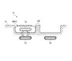
図5は、変形例に係るワイヤレス給電システムの保持部の一例を表す模式的な構成図である。図5は、当該ワイヤレス給電システムが適用される車両の内部を模式的に表している。図6は、変形例に係るワイヤレス給電システムの保持部の一例を表す模式的な断面図である。 FIG. 5 is a schematic configuration diagram illustrating an example of a holding unit of a wireless power feeding system according to a modification. FIG. 5 schematically shows the inside of a vehicle to which the wireless power feeding system is applied. FIG. 6 is a schematic cross-sectional view illustrating an example of a holding unit of a wireless power feeding system according to a modification.
図5、図6に示す変形例に係るワイヤレス給電システム1は、さらに、保持部14がキー穴部14A(図2等参照)にかえて収容部14Bを含んで構成される。 The wireless
ここで、本変形例の携帯機3である電子キー3Bは、キー穴部14Aに差し込まなくても、当該電子キー3Bを車両2の車内に持ち込んだ状態で、車両2側のスタート・停止ボタン等を操作することで車両2の動力源(エンジン等)を始動する形式のものである。そして、本変形例の保持部14は、電子キー3Bを収容する収容部14Bを含んで構成される。つまり、保持部14を構成する収容部14Bは、電子キー3Bを収容することで、当該電子キー3Bを、送電側コイル5aから受電側コイル6aへの電力の伝送が可能な位置に保持する。 Here, the electronic key 3B, which is the
収容部14Bは、例えば、車両2の車内のダッシュパネル、インストルメントパネル、コンソール、後部座席中央部等に設けられている。図5、図6の例では、収容部14Bは、車両2の車内前部のインストルメントパネル等の下方に設けられたコンソール2cに形成されている。収容部14Bは、コンソール2cと一体に形成される部材、あるいは、コンソール2cそのものに窪み状(トレイ状)に形成され、電子キー3B(携帯機3)を収容する。そして、送電側コイル5aは、電子キー3Bが収容部14Bに収容された状態で、電子キー3B側の受電側コイル6aと対向する位置に設けられる。送電側コイル5aは、この収容部14Bの底面側に埋め込まれている。ここでは、収容部14Bと送電側コイル5aとの組は、隣接するようにして2組設けられている。 The
上記変形例に係るワイヤレス給電システム1は、車両2の内部に設けられる収容部14Bに電子キー3B(携帯機3)が収容されることで、電子キー3Bを確実に保持することができ、その状態で、送電側コイル5aと電子キー3B側の受電側コイル6aとを近接させて対向させることができるので、確実に電力の伝送効率を向上することができる。 The wireless
なお、以上で説明したワイヤレス給電システムは、案内装置16を備えていなくてもよい。また、以上で説明した携帯機は、固有に保持する識別情報を送信して車両2に少なくとも1つ以上の動作を実行させる電子キー3A、3Bであるものとして説明したが、これに限らない。携帯機は、上述したように、ノートパソコン、携帯ゲーム機、携帯電話、タブレット端末等の種々の携帯端末機器であってもよい。 Note that the wireless power supply system described above may not include the
1 ワイヤレス給電システム
2 車両
3 携帯機
3A、3B 電子キー
4 電源
5 送電部
5a 送電側コイル
6 受電部
6a 受電側コイル
7 バッテリ(蓄電装置)
8 検出回路
9 携帯機側通信部
10 車両側通信部
11 制御回路(制御部)
12 非接触給電用トランス
13 通信部
14 保持部
14A キー穴部
14B 収容部
16 案内装置DESCRIPTION OF
8
12 Non-contact
Claims (6)
Translated fromJapanese前記車両に設けられた電源からの電力を前記受電側コイルに伝送する送電側コイルと、
前記車両の内部で前記送電側コイルから前記受電側コイルへの電力の伝送が可能な状態で、前記車両側通信部によって取得された前記蓄電装置の蓄電量に基づいて、前記送電側コイルから前記受電側コイルへ電力を伝送する制御を実行する制御部とを備えることを特徴とする、
ワイヤレス給電システム。A vehicle-side communication unit that stores the power received by the power-receiving coil in the power storage device and communicates with the portable device that is operated by the power stored in the power storage device inside the vehicle to obtain information about the power storage amount of the power storage device. ,
A power transmission side coil that transmits power from a power source provided in the vehicle to the power reception side coil;
Based on the amount of power stored in the power storage device acquired by the vehicle side communication unit in a state where power can be transmitted from the power transmission side coil to the power reception side coil inside the vehicle, the power transmission side coil And a control unit that executes control to transmit power to the power receiving coil.
Wireless power supply system.
前記携帯機の前記保持部への保持を促す旨の案内情報を出力する案内装置とを備え、
前記制御部は、前記車両側通信部によって取得された前記蓄電装置の蓄電量が予め設定される許容下限値以下である場合に、前記案内装置を制御し前記案内情報を出力させる、
請求項1に記載のワイヤレス給電システム。A holding unit that holds the portable device at a position where power can be transmitted from the power transmission side coil to the power reception side coil;
A guidance device that outputs guidance information for prompting the portable device to hold the portable device;
The control unit controls the guidance device to output the guidance information when a power storage amount of the power storage device acquired by the vehicle side communication unit is equal to or less than a preset allowable lower limit value;
The wireless power feeding system according to claim 1.
請求項1又は請求項2に記載のワイヤレス給電システム。The portable device is an electronic key that transmits identification information that is uniquely held to cause the vehicle to perform at least one operation.
The wireless power feeding system according to claim 1 or 2.
前記送電側コイルは、前記電子キーが前記キー穴部に挿入された状態で、前記受電側コイルと対向する位置に設けられる、
請求項3に記載のワイヤレス給電システム。The holding portion includes a keyhole portion into which the electronic key is inserted,
The power transmission side coil is provided at a position facing the power reception side coil in a state where the electronic key is inserted into the key hole portion.
The wireless power feeding system according to claim 3.
前記送電側コイルは、前記電子キーが前記収容部に収容された状態で、前記受電側コイルと対向する位置に設けられる、
請求項3に記載のワイヤレス給電システム。The holding unit is configured to include a storage unit that stores the electronic key,
The power transmission side coil is provided at a position facing the power reception side coil in a state where the electronic key is accommodated in the accommodation portion.
The wireless power feeding system according to claim 3.
請求項1乃至請求項5のいずれか1項に記載のワイヤレス給電システム。The communicable range between the portable device and the vehicle-side communication unit includes at least the interior of the vehicle in a state where the portable device is in the vehicle.
The wireless power feeding system according to any one of claims 1 to 5.
Priority Applications (1)
| Application Number | Priority Date | Filing Date | Title |
|---|---|---|---|
| JP2013244109AJP2015104253A (en) | 2013-11-26 | 2013-11-26 | Wireless power supply system |
Applications Claiming Priority (1)
| Application Number | Priority Date | Filing Date | Title |
|---|---|---|---|
| JP2013244109AJP2015104253A (en) | 2013-11-26 | 2013-11-26 | Wireless power supply system |
Publications (1)
| Publication Number | Publication Date |
|---|---|
| JP2015104253Atrue JP2015104253A (en) | 2015-06-04 |
Family
ID=53379530
Family Applications (1)
| Application Number | Title | Priority Date | Filing Date |
|---|---|---|---|
| JP2013244109AAbandonedJP2015104253A (en) | 2013-11-26 | 2013-11-26 | Wireless power supply system |
Country Status (1)
| Country | Link |
|---|---|
| JP (1) | JP2015104253A (en) |
Cited By (2)
| Publication number | Priority date | Publication date | Assignee | Title |
|---|---|---|---|---|
| EP3544148A1 (en) | 2018-03-20 | 2019-09-25 | Daihen Corporation | Power reception device and power reception control method |
| JP2021158794A (en)* | 2020-03-26 | 2021-10-07 | 綜合警備保障株式会社 | Terminal charging system, mobile terminals and chargers |
Citations (11)
| Publication number | Priority date | Publication date | Assignee | Title |
|---|---|---|---|---|
| JPH0714098Y2 (en)* | 1988-02-26 | 1995-04-05 | オムロン株式会社 | In-vehicle remote control device |
| JPH0937475A (en)* | 1995-07-24 | 1997-02-07 | Yuhshin Co Ltd | Keyless entry system |
| JPH09130864A (en)* | 1995-11-02 | 1997-05-16 | Yuhshin Co Ltd | Remote controller |
| JP2009301539A (en)* | 2008-05-13 | 2009-12-24 | Tokai Riken Kk | Security system |
| US20110148352A1 (en)* | 2008-09-12 | 2011-06-23 | Yuhua Wang | Holder for holding and charging mobile phone and bluetooth earset |
| JP2012010423A (en)* | 2010-06-22 | 2012-01-12 | Tokai Rika Co Ltd | Power transmission system |
| JP2012067530A (en)* | 2010-09-24 | 2012-04-05 | Tokai Rika Co Ltd | Charging system of electronic key |
| WO2012164743A1 (en)* | 2011-06-03 | 2012-12-06 | トヨタ自動車株式会社 | Vehicle, electric device, and power transmission/reception system |
| JP2013138529A (en)* | 2011-12-28 | 2013-07-11 | Seiko Epson Corp | Electronic apparatus, charging device and charging system |
| JP2013143803A (en)* | 2012-01-10 | 2013-07-22 | Seiko Epson Corp | Electronic apparatus, charging device, charging system and charging method |
| JP2013207819A (en)* | 2012-03-27 | 2013-10-07 | Panasonic Corp | Non-contact charger, program therefor and vehicle mounted with non-contact charger |
- 2013
- 2013-11-26JPJP2013244109Apatent/JP2015104253A/ennot_activeAbandoned
Patent Citations (11)
| Publication number | Priority date | Publication date | Assignee | Title |
|---|---|---|---|---|
| JPH0714098Y2 (en)* | 1988-02-26 | 1995-04-05 | オムロン株式会社 | In-vehicle remote control device |
| JPH0937475A (en)* | 1995-07-24 | 1997-02-07 | Yuhshin Co Ltd | Keyless entry system |
| JPH09130864A (en)* | 1995-11-02 | 1997-05-16 | Yuhshin Co Ltd | Remote controller |
| JP2009301539A (en)* | 2008-05-13 | 2009-12-24 | Tokai Riken Kk | Security system |
| US20110148352A1 (en)* | 2008-09-12 | 2011-06-23 | Yuhua Wang | Holder for holding and charging mobile phone and bluetooth earset |
| JP2012010423A (en)* | 2010-06-22 | 2012-01-12 | Tokai Rika Co Ltd | Power transmission system |
| JP2012067530A (en)* | 2010-09-24 | 2012-04-05 | Tokai Rika Co Ltd | Charging system of electronic key |
| WO2012164743A1 (en)* | 2011-06-03 | 2012-12-06 | トヨタ自動車株式会社 | Vehicle, electric device, and power transmission/reception system |
| JP2013138529A (en)* | 2011-12-28 | 2013-07-11 | Seiko Epson Corp | Electronic apparatus, charging device and charging system |
| JP2013143803A (en)* | 2012-01-10 | 2013-07-22 | Seiko Epson Corp | Electronic apparatus, charging device, charging system and charging method |
| JP2013207819A (en)* | 2012-03-27 | 2013-10-07 | Panasonic Corp | Non-contact charger, program therefor and vehicle mounted with non-contact charger |
Cited By (3)
| Publication number | Priority date | Publication date | Assignee | Title |
|---|---|---|---|---|
| EP3544148A1 (en) | 2018-03-20 | 2019-09-25 | Daihen Corporation | Power reception device and power reception control method |
| US11139691B2 (en) | 2018-03-20 | 2021-10-05 | Daihen Corporation | Power reception device and power reception control method |
| JP2021158794A (en)* | 2020-03-26 | 2021-10-07 | 綜合警備保障株式会社 | Terminal charging system, mobile terminals and chargers |
Similar Documents
| Publication | Publication Date | Title |
|---|---|---|
| US11491953B2 (en) | Mobile device and electronic key system for wireless communication with vehicle device | |
| CN104106192B (en) | Wireless charging device and method for controlling wireless charging | |
| JP5576511B2 (en) | Charging control apparatus and method, charging system, association method, and computer program | |
| JP5081783B2 (en) | Vehicle charging system | |
| CN105303653A (en) | Phone sleeve vehicle fob | |
| JP2014522337A (en) | In-vehicle personal device battery charging station and method of operation to avoid interference | |
| JP2011045190A (en) | Power transmission control unit, power transmission device, power reception control unit, power reception device, and electronic apparatus | |
| JP5975525B2 (en) | In-vehicle system, vehicle control apparatus, communication control method, and vehicle control method | |
| EP3282553B1 (en) | Locking/unlocking system | |
| CN103921683A (en) | Onboard System, Electronic Key System, And Control Unit | |
| CN109147098A (en) | It handles keyless entry and starts the method and system of remote controller battery self discharge | |
| JP2012161235A (en) | Vehicle communication system | |
| JP2016047983A (en) | Electronic key system | |
| JP2015140639A (en) | Electronic key system | |
| JP2013126301A (en) | Non-contact charger | |
| JP2015104253A (en) | Wireless power supply system | |
| KR101648793B1 (en) | Wireless power transmission system and method for supporting charging using multi-standard | |
| JP5756646B2 (en) | Contactless charging system | |
| JP2009287350A (en) | Vehicle control system and portable unit holding device | |
| JP2014150351A (en) | Car onboard system, communication device, power feeding device, and program | |
| JP2013188020A (en) | Power supply system with power theft prevention function | |
| JP5462095B2 (en) | Charger | |
| JP6767725B2 (en) | Wireless charging system for vehicles and wired wireless charging system for vehicles | |
| US20220337087A1 (en) | Inductive power and data transfer between mobile device and vehicle via common coil | |
| JP2013233027A (en) | Power-feeding device and charging device |
Legal Events
| Date | Code | Title | Description |
|---|---|---|---|
| A621 | Written request for application examination | Free format text:JAPANESE INTERMEDIATE CODE: A621 Effective date:20161020 | |
| A977 | Report on retrieval | Free format text:JAPANESE INTERMEDIATE CODE: A971007 Effective date:20170727 | |
| A131 | Notification of reasons for refusal | Free format text:JAPANESE INTERMEDIATE CODE: A131 Effective date:20170905 | |
| A521 | Request for written amendment filed | Free format text:JAPANESE INTERMEDIATE CODE: A523 Effective date:20171020 | |
| A131 | Notification of reasons for refusal | Free format text:JAPANESE INTERMEDIATE CODE: A131 Effective date:20180403 | |
| A762 | Written abandonment of application | Free format text:JAPANESE INTERMEDIATE CODE: A762 Effective date:20180424 |