Movatterモバイル変換


[0]ホーム

URL:


JP2015100624A - Cooker - Google Patents

Cooker
Download PDF

Info

Publication number
JP2015100624A
JP2015100624AJP2013245171AJP2013245171AJP2015100624AJP 2015100624 AJP2015100624 AJP 2015100624AJP 2013245171 AJP2013245171 AJP 2013245171AJP 2013245171 AJP2013245171 AJP 2013245171AJP 2015100624 AJP2015100624 AJP 2015100624A
Authority
JP
Japan
Prior art keywords
lid
inner lid
pan
locking
disposed
Prior art date
Legal status (The legal status is an assumption and is not a legal conclusion. Google has not performed a legal analysis and makes no representation as to the accuracy of the status listed.)
Granted
Application number
JP2013245171A
Other languages
Japanese (ja)
Other versions
JP6067546B2 (en
Inventor
坂口 洋一
Yoichi Sakaguchi
洋一 坂口
慎一郎 伊賀
Shinichiro Iga
慎一郎 伊賀
Current Assignee (The listed assignees may be inaccurate. Google has not performed a legal analysis and makes no representation or warranty as to the accuracy of the list.)
Zojirushi Corp
Original Assignee
Zojirushi Corp
Priority date (The priority date is an assumption and is not a legal conclusion. Google has not performed a legal analysis and makes no representation as to the accuracy of the date listed.)
Filing date
Publication date
Application filed by Zojirushi CorpfiledCriticalZojirushi Corp
Priority to JP2013245171ApriorityCriticalpatent/JP6067546B2/en
Publication of JP2015100624ApublicationCriticalpatent/JP2015100624A/en
Application grantedgrantedCritical
Publication of JP6067546B2publicationCriticalpatent/JP6067546B2/en
Activelegal-statusCriticalCurrent
Anticipated expirationlegal-statusCritical

Links

Images

Landscapes

Abstract

PROBLEM TO BE SOLVED: To reliably prevent improper use and damage by making a user immediately recognize non-placement of an inner lid.SOLUTION: A cooker 10 includes: a pot 11 having an upper-end opening for storing food materials; a lid body 31 for covering the upper part of the pot 11; an inner lid (an inner lid set 66) detachably disposed on a surface of the lid body 31 facing the pot 11 and closing the upper-end opening of the pot 11; and a lid regulation member 47. The lid regulation member 47 is configured to move the lid body 31 in a direction of closing the pot 11, with the inner lid 66 placed on the lid body 31, however, not to move the lid body 31 in the direction of closing the pot 11, with no inner lid 66 placed on the lid body 31.

Description

Translated fromJapanese

本発明は、調理器に関する。  The present invention relates to a cooking device.

調理器の1つである炊飯器は、鍋を着脱可能に収容する炊飯器本体と、炊飯器本体に回動可能に接続部で接続した蓋体とを備える。蓋体には、鍋内の排気を外部へ排出する排気通路が形成されている。また、蓋体には、鍋の上端開口を閉塞する内蓋が配設されている。内蓋には、鍋内に連通する排気孔が形成され、この内蓋と蓋体との間が排気通路の一部(上流側)を構成する。  A rice cooker, which is one of the cookers, includes a rice cooker body that detachably accommodates a pan, and a lid that is pivotally connected to the rice cooker body by a connecting portion. An exhaust passage for discharging the exhaust in the pan to the outside is formed in the lid. Moreover, the inner cover which obstruct | occludes the upper end opening of a pan is arrange | positioned at the cover body. An exhaust hole communicating with the inside of the pan is formed in the inner lid, and a portion (upstream side) of the exhaust passage is formed between the inner lid and the lid body.

特許文献1には、排気通路を構成する蓋体の下面および内蓋の上面を清掃可能とするために、蓋体に対して内蓋を着脱可能とした炊飯器が記載されている。この炊飯器は、蓋体に内蓋を装着していない状態で、炊飯器本体に対して蓋体を閉じることができないようにして、誤使用を防止している。蓋体の内蓋を装着する内蓋装着部には、蓋体の接続部側に内蓋を引っ掛けて係止する係止受部が設けられている。また、係止受部と逆の先端側には、内蓋を係止する係止部材がスライド可能に配設されている。この係止部材は、内蓋の装着により係止受部が蓋体から外向きに突出し、この係止受部に炊飯器本体のロック部材が係止される。内蓋の未装着状態では係止受部が蓋体内に没入し、係止受部に炊飯器本体のロック部材が係止できなくなる。その結果、炊飯器本体に対して蓋体を閉じた状態に維持できない。  Patent Document 1 describes a rice cooker in which an inner lid can be attached to and detached from a lid body so that the lower surface of the lid body and the upper surface of the inner lid can be cleaned. This rice cooker prevents misuse by preventing the lid body from being closed with respect to the rice cooker body when the lid is not fitted with an inner lid. The inner lid mounting portion for mounting the inner lid of the lid body is provided with a latch receiving portion for hooking and locking the inner lid on the connection portion side of the lid body. In addition, a locking member that locks the inner lid is slidably disposed on the tip side opposite to the locking receiving portion. In this locking member, when the inner lid is mounted, the locking receiving portion protrudes outward from the lid body, and the locking member of the rice cooker body is locked to the locking receiving portion. When the inner lid is not attached, the latch receiving portion is immersed in the lid body, and the lock member of the rice cooker body cannot be locked to the latch receiving portion. As a result, the lid cannot be kept closed with respect to the rice cooker body.

特許文献2には、蓋体の接続部に設けたダンパ機構により、蓋体をスムーズ(ゆっくり)に開閉できるようにした炊飯器が記載されている。ダンパ機構は、蓋体を開放方向に付勢するヒンジスプリングと、接続部に摺接するブレーキ部とを備え、摺接に伴う摩擦によりヒンジスプリングの付勢力に抗して制動力が作用するようにしている。制動力は開放角度が大きくなるに従って大きくなり、最大開放角度で最大となる。  Patent Document 2 describes a rice cooker in which a lid can be opened and closed smoothly (slowly) by a damper mechanism provided at a connection portion of the lid. The damper mechanism includes a hinge spring that urges the lid in the opening direction and a brake portion that slidably contacts the connecting portion, and a braking force acts against the urging force of the hinge spring due to friction caused by the slidable contact. ing. The braking force increases as the opening angle increases and becomes maximum at the maximum opening angle.

特許文献1の内蓋未装着防止機能と特許文献2のダンパ機能とは、1つの蓋体に両方が採用されることが多い。しかし、特許文献1の内蓋未装着防止機能は、ユーザが蓋体を閉じる際、炊飯器本体に対して蓋体を回動させ、ロックできないことで内蓋を装着し忘れていることを気付くことが多い。また、特許文献2のダンパ機能は、蓋体の制動力が蓋体の重量に大きな関連があり、重たいほど制動力が弱くなり、軽いほど制動力が強くなる。そのため、内蓋の重量が重い蓋体の場合、ロックできないことで内蓋の未装着を気付き、蓋体から手を離すと、勢いよく蓋体が開放するという不都合がある。この問題は、内蓋の重量が重くなるに従って顕著に現れ、最悪の場合には蓋体の接続部の破損に繋がる。  Both the inner lid non-mounting prevention function of Patent Document 1 and the damper function of Patent Document 2 are often employed in one lid. However, when the user closes the lid body, the inner lid non-mounting prevention function of Patent Document 1 turns out that the lid body is rotated with respect to the rice cooker body, and the user cannot forget to attach the inner lid because it cannot be locked. There are many cases. In addition, the damper function of Patent Document 2 has a large relationship between the braking force of the lid body and the weight of the lid body. The heavier the braking force, the weaker the braking force and the lighter the braking force. Therefore, when the weight of the inner lid is heavy, there is an inconvenience that when the lid is noticed that the inner lid is not attached because the inner lid cannot be locked and the hand is released from the lid, the lid is vigorously opened. This problem becomes more prominent as the weight of the inner lid becomes heavier, and in the worst case, it leads to breakage of the connecting portion of the lid.

特開平10−243873号公報JP-A-10-243873特開2004−16579号公報JP 2004-16579 A

本発明は、内蓋の装着し忘れを直ぐに認識できるようにして、誤使用および破損を確実に防止できる調理器を提供することを課題とする。  It is an object of the present invention to provide a cooking device that can immediately recognize that a user has forgotten to wear the inner lid and can reliably prevent misuse and damage.

前記課題を解決するため、本発明の調理器は、食材を収容する上端開口の鍋と、前記鍋の上部を覆う蓋体と、前記蓋体の前記鍋と対向する面に着脱可能に配設され、前記鍋の上端開口を閉塞する内蓋と、前記蓋体に前記内蓋が装着された状態で前記鍋を閉塞する方向に前記蓋体を移動可能とし、前記蓋体に前記内蓋が装着されていない状態で前記鍋を閉塞する方向に前記蓋体を移動不可能とする蓋規制部材と、を備える構成としている。具体的には、前記鍋を配設し、前記蓋体が回動可能に接続部で接続される調理器本体を備え、前記蓋規制部材は、前記蓋体内に配設され、前記内蓋が装着されていない状態で前記接続部に係止することにより前記蓋体を回動不可能にしている。  In order to solve the above-mentioned problem, the cooking device of the present invention is detachably disposed on a pan having an upper end opening for containing ingredients, a lid covering the top of the pan, and a surface of the lid facing the pan. An inner lid that closes the upper end opening of the pan, and the lid is movable in a direction in which the pan is closed while the inner lid is attached to the lid, and the inner lid is attached to the lid. And a lid regulating member that prevents the lid from moving in the direction of closing the pan in a state where it is not attached. Specifically, the pan is provided, and the cooker main body is connected to the lid by a connecting portion so that the lid is rotatable, the lid regulating member is arranged in the lid, and the inner lid is The lid is made non-rotatable by being locked to the connecting portion when not attached.

この調理器は、蓋体に内蓋を装着していない状態の場合、蓋規制部材によって蓋体を閉塞する方向に移動できないようにするため、ユーザに対して内蓋の装着し忘れを直ぐに認識させることができる。言い換えれば、蓋体を調理器本体に対する閉塞する位置まで移動させることができない。よって、蓋体に内蓋を装着するために、ユーザが蓋体から手を離しても、ヒンジスプリングの付勢力によって蓋体が勢いよく開放することはない。即ち、内蓋を装着しなければ蓋体を移動させることができないため、蓋体の安定した開閉を実現できる。そのため、蓋体の破損を防止できるとともに、内蓋の未装着状態で使用するという誤使用を確実に防止できる。  This cooker immediately recognizes that the user has forgotten to attach the inner lid to prevent the lid from moving in the direction of closing the lid by the lid regulating member when the inner lid is not attached to the lid. Can be made. In other words, the lid cannot be moved to a position where it closes with respect to the cooker body. Therefore, even if the user removes his / her hand from the lid in order to attach the inner lid to the lid, the lid does not open vigorously due to the biasing force of the hinge spring. That is, since the lid cannot be moved unless the inner lid is attached, the lid can be stably opened and closed. Therefore, it is possible to prevent the lid from being damaged, and to reliably prevent misuse of using the lid without the inner lid attached.

前記蓋規制部材は、前記蓋体の前記内蓋を装着する内蓋装着部に前記内蓋が装着されていない状態で、前記内蓋装着部に突出する干渉部と前記接続部に係止する係止部とを備え、前記内蓋装着部に前記内蓋が装着されることにより、前記干渉部が前記蓋体内の側に後退することにより前記接続部との係止が解除される。この場合、前記内蓋装着部は、前記接続部側に前記内蓋を引っ掛けて係止する係止受部を備え、前記蓋規制部材は、前記係止受部内に突出するように配設されている。このようにすれば、蓋規制部材を有する規制機構の簡素化を図ることができる。  The lid regulating member is engaged with the interference portion protruding from the inner lid mounting portion and the connecting portion in a state where the inner lid is not mounted on the inner lid mounting portion on which the inner lid of the lid is mounted. When the inner lid is mounted on the inner lid mounting portion, the interference portion is retracted toward the inside of the lid body, and the locking with the connection portion is released. In this case, the inner lid mounting portion includes a latch receiving portion that hooks and locks the inner lid on the connection portion side, and the lid regulating member is disposed so as to protrude into the latch receiving portion. ing. If it does in this way, simplification of the control mechanism which has a lid control member can be aimed at.

本発明の調理器では、蓋体に内蓋を装着していない場合、蓋体を閉塞する方向に移動できないため、ユーザに内蓋の装着し忘れを直ぐに認識させることができる。また、ヒンジスプリングの付勢力によって蓋体が勢いよく開放することはないため、蓋体の破損を防止できるとともに、内蓋の未装着状態で使用するという誤使用を確実に防止できる。  In the cooker according to the present invention, when the inner lid is not attached to the lid, the user cannot recognize that the user has forgotten to attach the inner lid because the lid cannot be moved in the closing direction. In addition, since the lid body does not open vigorously by the biasing force of the hinge spring, it is possible to prevent the lid body from being damaged, and to reliably prevent misuse when used without the inner lid attached.

本発明の実施形態の調理器を示す断面図。Sectional drawing which shows the cooker of embodiment of this invention.蓋体を開放して内蓋セットを外した状態を示す斜視図。The perspective view which shows the state which open | released the cover body and removed the inner cover set.蓋体の閉塞を規制する機構を示す背面図。The rear view which shows the mechanism which controls obstruction | occlusion of a cover body.調理器本体のヒンジ接続部を示す斜視図。The perspective view which shows the hinge connection part of a cooking appliance main body.蓋体を分解した状態を示す斜視図。The perspective view which shows the state which decomposed | disassembled the cover body.蓋規制部材を示す斜視図。The perspective view which shows a lid | cover control member.(A),(B)は蓋規制部材の作動を示す背面図。(A), (B) is a rear view which shows the action | operation of a lid | cover control member.内蓋セットを示す分解斜視図。The disassembled perspective view which shows an inner cover set.内蓋セットの分解断面図。The exploded sectional view of an inner lid set.

以下、本発明の実施の形態を図面を参照して説明する。  Hereinafter, embodiments of the present invention will be described with reference to the drawings.

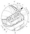
図1および図2は、本発明の実施形態に係る調理器10を示す。この調理器10は、調理物である食材を収容する調理鍋(鍋)11と、調理鍋11を着脱可能に収容する調理器本体15と、調理器本体15に開閉可能に配設した蓋体31とを備える。蓋体31は、閉じた状態で調理鍋11に対向する下面側に着脱可能に配設される内蓋セット(内蓋)66を備える。本実施形態では、内蓋セット66の未装着状態で蓋体31を閉塞する方向に移動できないようにして、内蓋セット66の装着し忘れを直ぐに認識させ、誤使用およびヒンジ接続部(接続部)24の破損を防止する。  1 and 2 show acooking device 10 according to an embodiment of the present invention. Thecooking device 10 includes a cooking pot (pan) 11 for storing ingredients that are cooked items, a cooking devicemain body 15 for detachably storing thecooking pan 11, and a lid disposed on the cooking devicemain body 15 so as to be opened and closed. 31. Thelid 31 includes an inner lid set (inner lid) 66 that is detachably disposed on the lower surface facing thecooking pan 11 in a closed state. In the present embodiment, when the inner lid set 66 is not attached, thelid body 31 cannot be moved in the closing direction, and the forgetting to attach the inner lid set 66 is immediately recognized. ) Prevent 24 damage.

図2に示すように、調理鍋11は、上端開口の有底円筒状をなし、熱伝導率が高い金属製母材の外面に電磁誘導によって加熱される金属材層を有する。この調理鍋11の鍋外周壁12の上端開口には、径方向外向きに突出するフランジ部13が形成されている。フランジ部13の径方向の対向位置には、一対の鍋取手14が取り付けられている。この鍋取手14は樹脂製であり、調理器本体15の外壁である胴体16より外方に突出する寸法で形成されている。  As shown in FIG. 2, thecooking pan 11 has a bottomed cylindrical shape with an upper end opening, and has a metal material layer heated by electromagnetic induction on the outer surface of a metal base material having high thermal conductivity. Aflange portion 13 projecting radially outward is formed at the upper end opening of the pan outerperipheral wall 12 of thecooking pan 11. A pair ofpan handles 14 are attached to opposing positions of theflange portion 13 in the radial direction. Thepan handle 14 is made of resin and has a dimension that projects outward from thebody 16 that is the outer wall of thecooker body 15.

図1および図2に示すように、調理器本体15は、有底筒状の胴体16と、胴体16の上端開口を覆う肩体18とを有する本体外装体を備える。胴体16には、横方向の両側に位置するように、鍋取手14の下部を覆う下側把持部17が設けられている。肩体18は樹脂製であり、胴体16の上端開口に嵌合される。この肩体18には、下側把持部17の上側に位置し、鍋取手14と隙間をあけて位置する上側把持部19が水平方向外向きに突設されている。肩体18の正面側(前方側)には操作パネル部20が形成されている。操作パネル部20の背面側(後方側)には、蓋体31によって覆われる凹部21が形成されている。凹部21の中央には、調理鍋11を着脱可能に収容する鍋収容部22が形成されている。凹部21には、鍋収容部22の正面側に蓋体31をロックするためのロック孔23が設けられている。また、凹部21には、鍋収容部22の背面側に蓋体31をヒンジピン41によって回動可能に接続するヒンジ接続部24が形成されている。  As shown in FIGS. 1 and 2, the cookermain body 15 includes a main body exterior body having a bottomedcylindrical body 16 and ashoulder body 18 that covers the upper end opening of thebody 16. Thebody 16 is provided with alower grip 17 that covers the lower portion of thepan handle 14 so as to be positioned on both sides in the lateral direction. Theshoulder body 18 is made of resin and is fitted into the upper end opening of thebody 16. Theshoulder 18 is provided with anupper grip 19 positioned above thelower grip 17 and spaced from the pan handle 14 so as to project outward in the horizontal direction. Anoperation panel 20 is formed on the front side (front side) of theshoulder body 18. On the back side (rear side) of theoperation panel unit 20, arecess 21 covered with thelid 31 is formed. In the center of therecess 21, apan accommodating portion 22 that detachably accommodates thecooking pan 11 is formed. Therecess 21 is provided with alock hole 23 for locking thelid 31 on the front side of thepot accommodating portion 22. In addition, therecess 21 is formed with ahinge connection portion 24 that connects thelid body 31 so as to be rotatable by ahinge pin 41 on the back side of thepot accommodating portion 22.

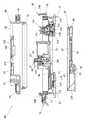
図3および図4に示すように、ヒンジ接続部24は、平面視凹字形状をなす隔壁部25と、ヒンジピン41を装着する軸受け金具28とを備える。隔壁部25は、鍋収容部22側に位置し、左右の幅方向に延びる端壁26を備える。この端壁26の上端は、蓋体31の回動(開放)を略90度で停止させるストッパの役割を兼ねる。この端壁26の一側(図4中右側)上端の背面側は、後述する蓋規制部材47が離脱可能に係止する係止受部26aを構成する。隔壁部25は、端壁26の両側下部から背面側へ突出する側壁27,27を備える。この側壁27,27は、下板32およびヒンジ接続部24を補強する補強リブの役割を兼ねる。軸受け金具28は、端壁26の背面側にネジ止めにより固定される。この軸受け金具28は、側壁27,27に沿って上向きに延びる一対のブラケット部29,29を備え、このブラケット部29の上端にヒンジピン41を装着する軸孔30が形成されている。  As shown in FIGS. 3 and 4, thehinge connection portion 24 includes apartition wall portion 25 having a concave shape in plan view, and a bearing fitting 28 to which thehinge pin 41 is attached. Thepartition part 25 is located in thepan accommodating part 22 side, and is provided with theend wall 26 extended in the left-right width direction. The upper end of theend wall 26 also serves as a stopper that stops the rotation (opening) of thelid 31 at approximately 90 degrees. The back side of the upper end of one side (right side in FIG. 4) of theend wall 26 constitutes alocking receiving portion 26a to which alid regulating member 47 described later is detachably locked. Thepartition wall portion 25 includesside walls 27 that protrude from the lower portions on both sides of theend wall 26 toward the back surface side. Theside walls 27 and 27 also serve as reinforcing ribs that reinforce thelower plate 32 and thehinge connecting portion 24. The bearing fitting 28 is fixed to the back side of theend wall 26 by screws. The bearing fitting 28 includes a pair ofbracket portions 29, 29 extending upward along theside walls 27, 27, and ashaft hole 30 for mounting thehinge pin 41 is formed at the upper end of thebracket portion 29.

鍋収容部22と胴体16との間の内部には、鍋収容部22に収容した調理鍋11の加熱手段である誘導加熱コイル(図示せず)が配設されている。また、鍋収容部22には、調理鍋11の温度を検出する第1温度検出部材である鍋温度センサ(図示せず)が、鍋収容部22を貫通して調理鍋11の底に接触するように配設されている。  An induction heating coil (not shown) that is a heating means of thecooking pan 11 accommodated in thepot accommodating portion 22 is disposed inside thepot accommodating portion 22 and thebody 16. In addition, a pot temperature sensor (not shown), which is a first temperature detection member that detects the temperature of thecooking pot 11, passes through thepot accommodating part 22 and contacts the bottom of thecooking pot 11. It is arranged like this.

図1および図5に示すように、蓋体31は、調理器本体15のヒンジ接続部24に回動可能に取り付けられ、調理鍋11の上端開口を含む調理器本体15の凹部21の上部を覆う。この蓋体31は、閉塞した状態で調理器本体15の上部を覆う下板32と、下板32の上部を覆う上板34とを有する蓋外装体を備える。下板32は樹脂製であり、鍋収容部22を含む凹部21の上方を覆う平面視形状の板材である。下板32の上部には金属製の補強板33が配設されている。上板34は樹脂製であり、下板32に上側から被せてネジ止めにより固定される下端開口のカバーである。この上板34の表面には装飾カバー35が配設されている。また、上板34の外周部には、鍋取手14の外周部を覆う取手カバー36が水平方向外向きに突設されている。  As shown in FIGS. 1 and 5, thelid 31 is rotatably attached to thehinge connection portion 24 of thecooker body 15, and covers the upper portion of therecess 21 of thecooker body 15 including the upper end opening of thecooking pan 11. cover. Thelid body 31 includes a lid exterior body having alower plate 32 that covers the upper portion of thecooker body 15 in a closed state and anupper plate 34 that covers the upper portion of thelower plate 32. Thelower plate 32 is made of resin, and is a plate material having a plan view shape that covers the upper portion of therecess 21 including thepot accommodating portion 22. Ametal reinforcing plate 33 is disposed on thelower plate 32. Theupper plate 34 is made of resin, and is a cover with a lower end opening that covers thelower plate 32 from above and is fixed by screwing. Adecorative cover 35 is disposed on the surface of theupper plate 34. In addition, ahandle cover 36 that covers the outer peripheral portion of the pan handle 14 protrudes outward in the horizontal direction on the outer peripheral portion of theupper plate 34.

下板32の正面側には、調理器本体15のロック孔23にロックされるロック部材37が回動可能に配設されている。上板34には、ロック部材37を回動させて、ロック孔23との係合を解除するための操作部材38が配設されている。また、補強板33を含む下板32の背面側には、調理器本体15のヒンジ接続部24に回動可能に接続される一対の蓋体側接続部39,39が形成されている。これら蓋体側接続部39,39間に軸受け金具28のブラケット部29を配置し、ブラケット部29,29間にヒンジスプリング(付勢部材)40を配置して、ヒンジピン41を貫通させて配設する。この状態で、軸受け金具28を調理器本体15のヒンジ接続部24にネジ止めして固定することにより、調理器本体15に対して蓋体31が回動可能に装着される。  On the front side of thelower plate 32, alock member 37 that is locked to thelock hole 23 of thecooker body 15 is rotatably disposed. Anoperation member 38 for releasing the engagement with thelock hole 23 by rotating thelock member 37 is disposed on theupper plate 34. In addition, a pair of lid-side connection portions 39 and 39 that are rotatably connected to thehinge connection portion 24 of thecooker body 15 are formed on the back side of thelower plate 32 including the reinforcingplate 33. Abracket portion 29 of the bearing fitting 28 is disposed between the lid-side connection portions 39, 39, a hinge spring (biasing member) 40 is disposed between thebracket portions 29, 29, and thehinge pin 41 is disposed therethrough. . In this state, thelid 31 is rotatably attached to the cookermain body 15 by screwing and fixing the bearing fitting 28 to thehinge connection portion 24 of the cookermain body 15.

図1および図2に示すように、蓋体31において、調理鍋11と対向する下板(面)32には、内蓋セット66を着脱可能に装着する内蓋装着部42が設けられている。この内蓋装着部42は、内蓋セット66の外形と略同一形状で上向きに隆起した第1配設部43と、後述する上側カバー部材68の外形と略同一形状で更に上向きに隆起した第2配設部44とを備える。第1配設部43には、蓋体側接続部39側に内蓋セット66を引っ掛けて係止する第1係止受部(係止受部)45,45が設けられている。また、第1配設部43には、蓋体側接続部39と逆側に位置する先端に、内蓋セット66の蓋係止部材75を離脱可能に係止する第2係止受部46が設けられている。  As shown in FIGS. 1 and 2, in thelid 31, the lower plate (surface) 32 facing thecooking pan 11 is provided with an innerlid mounting portion 42 for detachably mounting the inner lid set 66. . The innerlid mounting portion 42 has a first disposingportion 43 that protrudes upward in substantially the same shape as the outer shape of the inner lid set 66, and a first protrusion that protrudes further upward in substantially the same shape as the outer shape of anupper cover member 68 described later. 2 disposingportion 44. The first disposingportion 43 is provided with first locking receiving portions (locking receiving portions) 45 and 45 for hooking and locking the inner lid set 66 on the lid-side connecting portion 39 side. Further, the first disposingportion 43 has a secondlocking receiving portion 46 that removably locks thelid locking member 75 of the inner lid set 66 at the tip located on the opposite side to the lidside connection portion 39. Is provided.

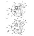
第1係止受部45,45の一方(図2中左側)には、内蓋装着部42に内蓋セット66が装着された場合に蓋体31を閉塞する方向に回動可能とし、内蓋装着部42に内蓋セット66が装着されていない場合に蓋体31を閉塞する方向に回動不可能とする、蓋規制部材47が配設されている。この蓋規制部材47は、蓋体31内に位置するように、下板32上に移動可能に配設される。  One of the firstlocking receiving portions 45, 45 (left side in FIG. 2) is rotatable in a direction to close thelid 31 when the inner lid set 66 is attached to the innerlid attaching portion 42. Alid restricting member 47 is provided that prevents thelid body 31 from rotating in the direction of closing thelid body 31 when the inner lid set 66 is not attached to thelid mounting portion 42. Thelid regulating member 47 is movably disposed on thelower plate 32 so as to be located in thelid 31.

図4および図6に示すように、蓋規制部材47は、内蓋装着部42の第1係止受部45内に幅方向の外側から突出可能な干渉部48を備える。この干渉部48は、内蓋セット66の差込方向に沿って、内蓋装着部42の幅方向の外側から内側へ傾斜するテーパ面49を備える。干渉部48の逆側端部には、付勢スプリング51を位置決めする位置決め凸部50が設けられている。図3に示すように、位置決め突起を設けた干渉部48の逆側端と下板32との間には付勢スプリング(付勢部材)51が配設され、この付勢スプリング51によって干渉部48が第1係止受部45内に突出した進出位置に付勢される。蓋規制部材47の移動(進退)方向である干渉部48と位置決め凸部50との間には、移動方向に対して直交方向背面側に突出する連結部52が設けられている。  As shown in FIGS. 4 and 6, thelid regulating member 47 includes aninterference portion 48 that can project from the outside in the width direction in the firstlocking receiving portion 45 of the innerlid mounting portion 42. Theinterference portion 48 includes a taperedsurface 49 that inclines inward from the outside in the width direction of the innerlid mounting portion 42 along the insertion direction of the inner lid set 66. A positioningconvex portion 50 for positioning the urgingspring 51 is provided at the opposite end of theinterference portion 48. As shown in FIG. 3, a biasing spring (biasing member) 51 is disposed between the opposite side end of theinterference portion 48 provided with the positioning projection and thelower plate 32, and theinterference portion 51 48 is biased to the advanced position projecting into the firstlocking receiving portion 45. Between theinterference part 48 and the positioningconvex part 50 which are the movement (advancing / retreating) direction of thelid regulating member 47, a connectingpart 52 is provided that protrudes to the rear side in the direction orthogonal to the moving direction.

蓋規制部材47は、調理器本体15のヒンジ接続部24(端壁26)の係止受部26aに係止可能なヒンジ係止部(係止部)53を備える。このヒンジ係止部53は所定肉厚の板状であり、連結部52に連結するための連結片54と、ヒンジ係止部53をヒンジ接続部24に対して剛性が高い縁側で係止させるための連続部55とを備える。連結片54は、ヒンジ接続部24側である下向きに突出している。連続部55は、連結部52の下側に折り込まれている。この連続部55の縁に略L字形状をなすように折り曲げたヒンジ係止部53が形成される。このヒンジ係止部53は、調理器本体15に対して蓋体31を略90度開放させた状態で、ヒンジ接続部24の端壁26に対して背面側に係止する。  Thelid regulating member 47 includes a hinge locking portion (locking portion) 53 that can be locked to thelocking receiving portion 26 a of the hinge connection portion 24 (end wall 26) of thecooker body 15. Thehinge locking portion 53 is a plate having a predetermined thickness, and the connectingpiece 54 for connecting to the connectingportion 52 and thehinge locking portion 53 are locked to thehinge connecting portion 24 on the edge side having high rigidity. And acontinuous portion 55. The connectingpiece 54 protrudes downward on thehinge connecting portion 24 side. Thecontinuous portion 55 is folded below the connectingportion 52. Ahinge locking portion 53 is formed at the edge of thecontinuous portion 55 and is bent so as to form a substantially L shape. Thehinge locking portion 53 is locked to the back side with respect to theend wall 26 of thehinge connecting portion 24 in a state where thelid body 31 is opened by approximately 90 degrees with respect to the cookermain body 15.

蓋規制部材47は、図7(A)に示す内蓋セット66の未装着状態(進出位置)で、内蓋装着部42に内蓋セット66が装着されると、内蓋装着部42内に突出した干渉部48が内蓋セット66に押圧される。これにより、図7(B)に示すように、付勢スプリング51の付勢力に抗して、干渉部48が蓋体31内に没入した後退位置に移動する。その結果、ヒンジ係止部53が調理器本体15のヒンジ接続部24に係止した状態から、係止が解除された状態になる。また、図7(B)に示す内蓋セット66の装着状態(後退位置)で、内蓋装着部42から内蓋セット66が取り外されると、図7(A)に示すように、付勢スプリング51の付勢力によって後退位置から進出位置へ移動される。その結果、ヒンジ係止部53が調理器本体15のヒンジ接続部24の係止受部26aに係止した状態になる。  When the inner lid set 66 is attached to the innerlid mounting portion 42 in a state where the inner lid set 66 is not attached (advance position) as shown in FIG. The protrudinginterference part 48 is pressed against the inner lid set 66. Accordingly, as shown in FIG. 7B, theinterference portion 48 moves to the retracted position where theinterference portion 48 is immersed in thelid 31 against the urging force of the urgingspring 51. As a result, the state in which thehinge locking portion 53 is unlocked from the state in which thehinge locking portion 53 is locked to thehinge connecting portion 24 of thecooker body 15 is released. Further, when the inner lid set 66 is removed from the innerlid mounting portion 42 in the mounted state (retracted position) of the inner lid set 66 shown in FIG. 7B, as shown in FIG. The urging force of 51 moves from the retracted position to the advanced position. As a result, thehinge locking portion 53 is locked to thelocking receiving portion 26a of thehinge connecting portion 24 of thecooking device body 15.

本実施形態のヒンジ係止部53には、蓋体31の開放方向前側の縁に、基端側から先端側へ向けて開放方向後向きに傾斜するガイド縁部56が設けられている。このガイド縁部56は、調理器本体15に対して蓋体31が90度未満の開放状態で内蓋セット66が取り外されると、ヒンジスプリング40による開放方向の付勢力で、端壁26の正面側に当接する。そして、蓋規制部材47を付勢スプリング51の付勢力に抗して進出位置から後退位置に移動させた後、端壁26の背面側を越えることで、付勢スプリング51の付勢力で係止するように構成している。  Thehinge locking portion 53 of the present embodiment is provided with aguide edge portion 56 that is inclined backward in the opening direction from the base end side toward the distal end side at the edge of thelid body 31 in the opening direction front side. When the inner lid set 66 is removed with thelid 31 being less than 90 degrees open relative to the cookermain body 15, theguide edge 56 is biased in the opening direction by thehinge spring 40, and the front edge of theend wall 26. Abut on the side. Then, after thelid regulating member 47 is moved from the advanced position to the retracted position against the urging force of the urgingspring 51, thelid regulating member 47 is locked by the urging force of the urgingspring 51 by crossing the back side of theend wall 26. It is configured to do.

図1および図2に示すように、蓋体31には、調理鍋11内と外部とを連通させ、調理鍋11内の排気(蒸気)を外部へ排出するための排気通路65,70が形成されている。そのうち、下流側排気通路65は蓋体31に設けられ、上流側排気通路70は内蓋セット66に設けられている。  As shown in FIGS. 1 and 2, thelid 31 is formed withexhaust passages 65 and 70 for allowing the inside of thecooking pan 11 to communicate with the outside and exhausting the exhaust (steam) inside thecooking pan 11 to the outside. Has been. Among them, thedownstream exhaust passage 65 is provided in thelid 31, and theupstream exhaust passage 70 is provided in the inner lid set 66.

具体的には、下板32には、第2配設部44の蓋体側接続部39側に、下流側排気通路65の入口である接続口57が設けられている。図1および図5に示すように、上板34には、接続口57の上部に位置するように、蒸気口ユニット60を着脱可能に配設する蒸気口ユニット配設部58が設けられている。この蒸気口ユニット配設部58には、接続口57上に位置するように挿通孔59が設けられている。接続口57と挿通孔59との間と、接続口57の内蓋セット66側には、パッキンが配設されている。蒸気口ユニット60は、有底円筒状の下容器61と、平面視矩形状の上カバー63とを備える。下容器61には、挿通孔59に差し込まれる円筒状の接続筒部62が設けられている。上カバー63には、蒸気を外部へ放出するための排出口64が設けられている。そして、下板32の接続口57から蒸気口ユニット60の排出口64までの流路が下流側排気通路65を構成する。  Specifically, thelower plate 32 is provided with aconnection port 57 that is an inlet of thedownstream exhaust passage 65 on the lid-side connection portion 39 side of thesecond arrangement portion 44. As shown in FIGS. 1 and 5, theupper plate 34 is provided with a steam portunit disposing portion 58 for removably disposing thesteam port unit 60 so as to be positioned above theconnection port 57. . The steam portunit arrangement portion 58 is provided with aninsertion hole 59 so as to be positioned on theconnection port 57. Packing is disposed between theconnection port 57 and theinsertion hole 59 and on the inner lid set 66 side of theconnection port 57. Thesteam port unit 60 includes a bottomed cylindricallower container 61 and a rectangularupper cover 63 in plan view. Thelower container 61 is provided with a cylindrical connectingtube portion 62 that is inserted into theinsertion hole 59. Theupper cover 63 is provided with adischarge port 64 for releasing steam to the outside. A flow path from theconnection port 57 of thelower plate 32 to thedischarge port 64 of thesteam port unit 60 constitutes adownstream exhaust passage 65.

図1および図2に示すように、蓋体31の内蓋装着部42には、調理鍋11の上端開口を閉塞する内蓋セット66が着脱可能に配設される。この内蓋セット66は、図8および図9に示すように、調理鍋11を閉塞する内蓋本体67と、内蓋本体67の上面側に着脱可能に装着される上側カバー部材68と、内蓋本体67の下面側に着脱可能に装着される下側カバー部材69とを備える。そして、内蓋本体67と上側カバー部材68との間に、下流側排気通路65に連通し、液状物を収容する空間の役割を兼ねる上流側排気通路70が形成(画定)される。  As shown in FIGS. 1 and 2, an inner lid set 66 that closes the upper end opening of thecooking pan 11 is detachably disposed on the innerlid mounting portion 42 of thelid 31. As shown in FIGS. 8 and 9, the inner lid set 66 includes aninner lid body 67 that closes thecooking pan 11, anupper cover member 68 that is detachably attached to the upper surface side of theinner lid body 67, Alower cover member 69 detachably attached to the lower surface side of the lidmain body 67. Anupstream exhaust passage 70 that communicates with thedownstream exhaust passage 65 and also serves as a space for storing the liquid material is formed (defined) between the inner lidmain body 67 and theupper cover member 68.

内蓋本体67は、受け皿形状をなす金属製の閉塞板71を備える。閉塞板71の外周部には、調理鍋11の上端開口の内周面に密着されるシール部材72が配設される。このシール部材72は、閉塞板71の外周部に樹脂製の枠体73を配設することにより、これらの間に挟み込んで装着される。  Theinner lid body 67 includes ametal closing plate 71 having a saucer shape. A sealingmember 72 that is in close contact with the inner peripheral surface of the upper end opening of thecooking pan 11 is disposed on the outer peripheral portion of theclosing plate 71. The sealingmember 72 is mounted by being sandwiched between the sealingmember 71 by disposing aresin frame 73 on the outer peripheral portion of theclosing plate 71.

枠体73には、蓋体31の内蓋装着部42の第1係止受部45に係止される一対の係止部74,74が、後方外向きに突出するように設けられている。この係止部74が蓋規制部材47の干渉部48に当接することにより、蓋規制部材47を進出位置から後退位置へ移動される。係止部74,74間の径方向の対向位置には、蓋体31のヒンジ接続部24と逆側に位置する第2係止受部46に離脱可能に係止される蓋係止部材75が配設されている。この蓋係止部材75は、径方向にスライド可能に配設され、図示しないスプリング(付勢部材)によって外向きに付勢されている。  Theframe body 73 is provided with a pair of lockingportions 74 and 74 that are locked to the firstlocking receiving portion 45 of the innerlid mounting portion 42 of thelid body 31 so as to protrude rearward and outward. . When the lockingportion 74 comes into contact with theinterference portion 48 of thelid regulating member 47, thelid regulating member 47 is moved from the advanced position to the retracted position. Alid locking member 75 that is detachably locked to the secondlocking receiving portion 46 located on the opposite side of thehinge connecting portion 24 of thelid body 31 at a radially opposing position between the lockingportions 74, 74. Is arranged. Thelid locking member 75 is slidably arranged in the radial direction and is urged outward by a spring (biasing member) (not shown).

また、内蓋本体67には、上側カバー部材68を着脱可能に装着するための一対の上カバー係止受部76A,76Bが、枠体73の径方向に対向する位置に上向きに突出するように設けられている。また、内蓋本体67には、下側カバー部材69を係止する一対の下カバー係止受部77が枠体73の径方向に対向する位置に設けられている。なお、ヒンジ接続部24側に位置する下カバー係止受部77は図示していない。  Theinner lid body 67 has a pair of upper cover latching receivingportions 76A and 76B for detachably mounting theupper cover member 68 so as to protrude upward at positions facing the radial direction of theframe 73. Is provided. Further, theinner lid body 67 is provided with a pair of lower coverlocking receiving portions 77 that lock thelower cover member 69 at positions facing the radial direction of theframe body 73. In addition, the lower coverlatching receiving part 77 located in thehinge connection part 24 side is not shown in figure.

上側カバー部材68は、内蓋本体67の上部を覆うように開放可能に取り付けられ、内蓋本体67との間に液状物を収容する空間の役割を兼ねる上流側排気通路70を形成する。この上側カバー部材68は、受け皿形状をなす閉塞板71の内側に嵌合される下端開口の筒形状である。上側カバー部材68の天壁78は、閉塞板71に対して所定間隔(例えば約31.9mm)をもって位置する。また、上側カバー部材68の下端には、閉塞板71に圧接されて内蓋本体67と上側カバー部材68とを密閉するシール部材79が配設されている。  Theupper cover member 68 is releasably attached so as to cover the upper portion of the inner lidmain body 67, and forms anupstream exhaust passage 70 that also serves as a space for storing a liquid material between theupper cover member 67. Theupper cover member 68 has a cylindrical shape with a lower end opening that is fitted inside the closingplate 71 having a tray shape. Thetop wall 78 of theupper cover member 68 is positioned with a predetermined interval (for example, about 31.9 mm) with respect to theclosing plate 71. Aseal member 79 is disposed at the lower end of theupper cover member 68 to seal theinner lid body 67 and theupper cover member 68 in pressure contact with the closingplate 71.

上側カバー部材68には、内蓋本体67に対して離脱可能に係止する第1および第2係止部材80,81がスライド可能に配設されている。上カバー係止受部76Aに係止される第1係止部材80は、図示しないスプリング(付勢部材)によって径方向外向きに付勢されている。上カバー係止受部76Bに係止される第2係止部材81は、上側カバー部材68を内蓋本体67から取り外すための開放操作部82を備え、図示しないスプリング(付勢部材)によって径方向外向きに付勢されている。  Theupper cover member 68 is slidably disposed with first andsecond locking members 80 and 81 that are detachably locked with respect to theinner lid body 67. Thefirst locking member 80 locked to the upper cover locking receivingportion 76A is biased radially outward by a spring (biasing member) (not shown). Thesecond locking member 81 locked to the upper cover locking receivingportion 76B includes anopening operation portion 82 for removing theupper cover member 68 from theinner lid body 67, and has a diameter by a spring (biasing member) (not shown). It is biased outward in the direction.

上側カバー部材68を内蓋本体67に装着することにより、上流側排気通路70が形成される。内蓋本体67には後述する調圧弁99が配設され、この調圧弁99の連通孔102が上流側排気通路70の入口を構成する。上側カバー部材68の天壁78には、蓋体31の下流側排気通路65の接続口57に対応するように接続口83が設けられ、この接続口83が上流側排気通路70の出口を構成する。下流側排気通路65の接続口57と上流側排気通路70の接続口83とは、パッキンによって密閉される。  By attaching theupper cover member 68 to theinner lid body 67, theupstream exhaust passage 70 is formed. Theinner lid body 67 is provided with apressure regulating valve 99 described later, and thecommunication hole 102 of thepressure regulating valve 99 constitutes the inlet of the upstreamside exhaust passage 70. Aconnection port 83 is provided in thetop wall 78 of theupper cover member 68 so as to correspond to theconnection port 57 of thedownstream exhaust passage 65 of thelid 31, and thisconnection port 83 constitutes the outlet of theupstream exhaust passage 70. To do. Theconnection port 57 of thedownstream exhaust passage 65 and theconnection port 83 of theupstream exhaust passage 70 are sealed with packing.

下側カバー部材69は、内蓋本体67に対して調理鍋11内を臨む側に着脱可能に配設される。そして、調理(装着)時には、調理鍋11を臨む連通孔102が食材の繊維や崩れ落ちた食材片等によって目詰まりすることを防止する。この下側カバー部材69は、多数の通気孔を形成した金属製の下側カバー本体84と、下側カバー本体84の外周部を囲むカバーリング85とを備える。  Thelower cover member 69 is detachably disposed on the side facing the inside of thecooking pan 11 with respect to theinner lid body 67. And at the time of cooking (mounting | wearing), it prevents that the communicatinghole 102 which faces thecooking pan 11 is clogged with the fiber of a foodstuff, the piece of foodstuff which fell down, etc. Thelower cover member 69 includes a metallower cover body 84 in which a large number of ventilation holes are formed, and acover ring 85 that surrounds the outer periphery of thelower cover body 84.

カバーリング85には、内蓋本体67の下カバー係止受部77に係止される係止部86,87が設けられている。第1係止部86は一対の突片からなり、第2係止部87はスライド可能に配設した係止部材88に設けられている。係止部材88は、内蓋本体67から取り外すための取外操作部89を備え、図示しないスプリング(付勢部材)によって径方向外向きに付勢されている。  Thecover ring 85 is provided with lockingportions 86 and 87 that are locked to the lower coverlocking receiving portion 77 of the inner lidmain body 67. The 1st latching | lockingpart 86 consists of a pair of protrusion, and the 2nd latching | lockingpart 87 is provided in the latchingmember 88 arrange | positioned so that sliding is possible. The lockingmember 88 includes aremoval operation portion 89 for removing from theinner lid body 67, and is biased radially outward by a spring (biasing member) (not shown).

本実施形態の調理器10は、調理鍋11内を大気圧より高い圧力に昇圧するための密閉機構と、上流側排気通路70内に流入した液状物を調理鍋11に還流させるための還流機構と、を搭載している。密閉機構は、内蓋本体67に配設した2個の開閉弁98,99と、下板32に配設した2組の駆動機構と、を備える。還流機構は、内蓋本体67に配設した2個の開閉弁100,101と、下板32に配設した1組の駆動機構および内蓋本体67に配設した1組の駆動機構と、を備える。また、蓋体31には、調理鍋11内の圧力を検出する圧力検出部材である圧力センサ93が配設されるとともに、上流側排気通路70内の蒸気温度を検出する第2温度検出部材である蓋温度センサ94が配設される。4個の開閉弁98〜101と、圧力センサ93のダクト97により、内蓋セット66の重量が重くなっている。  Thecooker 10 of this embodiment includes a sealing mechanism for increasing the pressure in thecooking pan 11 to a pressure higher than the atmospheric pressure, and a reflux mechanism for returning the liquid material flowing into theupstream exhaust passage 70 to thecooking pan 11. And is equipped. The sealing mechanism includes two on-offvalves 98 and 99 disposed on the inner lidmain body 67 and two sets of driving mechanisms disposed on thelower plate 32. The reflux mechanism includes two on-offvalves 100 and 101 disposed on theinner lid body 67, a set of driving mechanisms disposed on thelower plate 32, and a set of driving mechanisms disposed on theinner lid body 67; Is provided. Further, thelid 31 is provided with apressure sensor 93 which is a pressure detection member for detecting the pressure in thecooking pan 11 and is a second temperature detection member for detecting the steam temperature in the upstreamside exhaust passage 70. Alid temperature sensor 94 is provided. The weight of the inner lid set 66 is increased by the four on-offvalves 98 to 101 and theduct 97 of thepressure sensor 93.

具体的には、図5に示すように、下板32の第2配設部44の上部には、内蓋セット66の開閉弁98〜100を開閉駆動するための駆動手段としてソレノイド90がそれぞれ配設されている。ソレノイド90のロッドには、水平方向の移動を垂直方向の移動(駆動力)に変換するためのカム部材91が配設され、その下部に図示しない駆動部材が配設されている。また、下板32には、駆動部材を進退可能とする開口部が設けられ、各開口部にパッキン92が配設されている。また、下板32の第2配設部44の上部には、圧力センサ93および蓋温度センサ94が配設されている。下板32には、各センサ93,94の下部に開口部が設けられ、各開口部に筒状パッキン95が配設されている。  Specifically, as shown in FIG. 5,solenoids 90 serving as driving means for opening and closing the on-offvalves 98 to 100 of the inner lid set 66 are provided above the second disposingportion 44 of thelower plate 32. It is arranged. The rod of thesolenoid 90 is provided with acam member 91 for converting a horizontal movement into a vertical movement (driving force), and a driving member (not shown) is disposed below thecam member 91. Further, thelower plate 32 is provided with openings that allow the drive member to advance and retreat, and a packing 92 is disposed in each opening. In addition, apressure sensor 93 and alid temperature sensor 94 are disposed above thesecond disposition portion 44 of thelower plate 32. Thelower plate 32 is provided with openings at the lower portions of thesensors 93 and 94, and acylindrical packing 95 is provided at each opening.

図8および図9に示すように、内蓋本体67には、樹脂製のベース部材96が配設されている。このベース部材96には、圧力センサ93の下部に位置するように、調理鍋11内に連通するダクト97が形成されている。また、ベース部材96には、下板32上に配設した3個のソレノイド90によってそれぞれ開閉駆動される、安全弁98、調圧弁99および電動式還流弁100が配設されている。また、接続口83の下部に位置するように、連動式還流弁101が配設されている。  As shown in FIGS. 8 and 9, aresin base member 96 is disposed on theinner lid body 67. Thebase member 96 is formed with aduct 97 communicating with thecooking pan 11 so as to be positioned below thepressure sensor 93. Thebase member 96 is provided with asafety valve 98, apressure regulating valve 99, and anelectric reflux valve 100 that are driven to open and close by threesolenoids 90 disposed on thelower plate 32, respectively. In addition, an interlockingreflux valve 101 is disposed so as to be positioned below theconnection port 83.

電動式の開閉弁98〜100は、調理鍋11内に連通する連通孔102と、この連通孔102を開放可能に密閉する弁体103とを備える。弁体103の上部には、駆動部材の駆動力を受ける作動受部材104が配設されている。弁体103と作動受部材104との間には、弁体103を連通孔102側へ向けて付勢する図示しないスプリング(付勢部材)が配設されている。安全弁98および調圧弁99の弁体103は連通孔102を上方から密閉し、電動式還流弁100の弁体103は連通孔102を下方から密閉する点で相違する。連動式還流弁101は、調理鍋11内に連通する還流孔105と、この還流孔105を開放可能に上方から密閉する弁体106とを備える。弁体106は、還流孔105を通して調理鍋11内の側へ突出する作動受部107を備える。  The electric on-offvalves 98 to 100 include acommunication hole 102 that communicates with thecooking pan 11 and avalve body 103 that seals thecommunication hole 102 so that thecommunication hole 102 can be opened. Anoperation receiving member 104 that receives the driving force of the driving member is disposed on thevalve body 103. Between thevalve body 103 and theoperation receiving member 104, a spring (biasing member) (not shown) that urges thevalve body 103 toward thecommunication hole 102 is disposed. Thevalve body 103 of thesafety valve 98 and thepressure regulating valve 99 is different in that thecommunication hole 102 is sealed from above, and thevalve body 103 of theelectric reflux valve 100 is sealed from below. The interlockingreflux valve 101 includes areflux hole 105 communicating with thecooking pan 11 and avalve body 106 that seals thereflux hole 105 from above so as to be openable. Thevalve body 106 includes anoperation receiving portion 107 that protrudes toward the inside of thecooking pan 11 through thereflux hole 105.

上側カバー部材68には、電動式の開閉弁98〜100に対応する開口部が設けられ、各開口部にパッキン108が配設されている。また、圧力センサ93に対応する開口部が設けられ、この開口部にダクト97に圧接される筒状パッキン109が配設されている。また、筒状パッキン109の横に、いずれの機構とも対応しない開口部が設けられ、この開口部に上流側排気通路70内を透視可能な透明樹脂からなる窓部110が配設されている。また、蓋温度センサ94に対応する開口部111が設けられている。各パッキン108,109は、金属製の補強カバー112によって天壁78との間に挟み込んだ状態で位置決めされる。補強カバー112には、開口部111との対応位置を除く、各パッキン108,109および窓部110との対応位置に開口部113が設けられている。なお、蓋温度センサ94は、金属製の補強カバー112の開口部113の対応部分に接触し、この補強カバー112を介して上流側排気通路70の温度を検出する。  Theupper cover member 68 is provided with openings corresponding to the electric on-offvalves 98 to 100, and a packing 108 is disposed in each opening. In addition, an opening corresponding to thepressure sensor 93 is provided, and acylindrical packing 109 that is pressed against theduct 97 is disposed in the opening. In addition, an opening that does not correspond to any mechanism is provided beside thecylindrical packing 109, and awindow 110 made of a transparent resin that can be seen through theupstream exhaust passage 70 is disposed in the opening. Anopening 111 corresponding to thelid temperature sensor 94 is provided. Each packing 108 and 109 is positioned in a state of being sandwiched between thetop wall 78 by ametal reinforcing cover 112. The reinforcingcover 112 is provided withopenings 113 at positions corresponding to thepackings 108 and 109 and thewindow 110 except for positions corresponding to theopenings 111. Thelid temperature sensor 94 comes into contact with a corresponding portion of theopening 113 of themetal reinforcing cover 112 and detects the temperature of theupstream exhaust passage 70 via the reinforcingcover 112.

連動式還流弁101を開閉するための弁開閉部材114は、内蓋本体67の調理鍋11内を臨む下面に配設されている。この弁開閉部材114は、連動式還流弁101の下部に位置するように、内蓋本体67の開閉部材カバー115内に配設されている。弁開閉部材114は、蓋体31を閉じることにより調理鍋11の鍋外周壁12に当接して後退した後退位置、および、蓋体31の開放により進出した進出位置の間を移動可能であり、図示しないスプリング(付勢部材)により進出位置へ付勢されている。また、弁開閉部材114には、進出位置で弁体106を上向きに移動させて還流孔105を開放し、後退位置で弁体106を下向きに移動させて還流孔105を密閉するためのカム部116が設けられている。  A valve opening / closingmember 114 for opening / closing the interlockingreflux valve 101 is disposed on the lower surface of theinner lid body 67 facing thecooking pan 11. The valve opening / closingmember 114 is disposed in the opening / closingmember cover 115 of the inner lidmain body 67 so as to be positioned below the interlockingreflux valve 101. The valve opening / closingmember 114 is movable between a retracted position retracted by contacting the pan outerperipheral wall 12 of thecooking pan 11 by closing thelid 31 and an advanced position advanced by opening thelid 31. It is urged to the advanced position by a spring (urging member) (not shown). Further, the valve opening / closingmember 114 has a cam portion for moving thevalve body 106 upward in the advanced position to open thereflux hole 105 and moving thevalve body 106 downward in the retracted position to seal thereflux hole 105. 116 is provided.

また、本実施形態の内蓋セット66は、下側カバー部材69を装着していない状態では、調理器本体15に対して蓋体31を閉じることができないようにするための干渉部材117が更に配設されている。この干渉部材117は、蓋体31の先端側に位置するように、内蓋本体67の枠体73に設けた干渉部材カバー118内に配設されている。この干渉部材カバー118のヒンジ接続部24側に、一方の下カバー係止受部77が形成されている。干渉部材117は、下側カバー部材69の装着により調理鍋11に干渉しない後退位置、および、下側カバーの取り外しにより調理鍋11に干渉するように進出した進出位置の間を移動可能であり、図示しないスプリング(付勢部材)により進出位置へ付勢されている。なお、下側カバー部材69は、内蓋本体67への装着により干渉部材117を後退位置へ移動させる押圧部119を備える。  Further, the inner lid set 66 of the present embodiment further includes aninterference member 117 for preventing thelid 31 from being closed with respect to thecooker body 15 when thelower cover member 69 is not attached. It is arranged. Theinterference member 117 is disposed in aninterference member cover 118 provided on theframe body 73 of the inner lidmain body 67 so as to be positioned on the distal end side of thelid body 31. One lower coverlocking receiving portion 77 is formed on thehinge connecting portion 24 side of theinterference member cover 118. Theinterference member 117 is movable between a retracted position that does not interfere with thecooking pan 11 by mounting thelower cover member 69 and an advanced position that has advanced so as to interfere with thecooking pan 11 by removing the lower cover, It is urged to the advanced position by a spring (urging member) (not shown). Thelower cover member 69 includes apressing portion 119 that moves theinterference member 117 to the retracted position by being attached to the inner lidmain body 67.

このように構成した内蓋セット66は、4個の開閉弁98〜101、連動式還流弁101を開閉させるための弁開閉部材114、下側カバー部材69の未装着状態では蓋体31を閉じることができないようにするための干渉部材117など、多数の機構を配設しているため、重量が重い。この内蓋セット66を装着した蓋体31は、複数の駆動機構の重量も従来の炊飯器等と比較すると、遥かに重い。そのため、操作部材38の操作により蓋体31を開放するには、ヒンジスプリング40による開放方向の付勢力は、大きく設定される。逆に、蓋体31が勢いよく開放することを防止するダンパ機構(図示せず)の制動力は、極めて小さく設定される。そのため、蓋体31に内蓋セット66を装着していない状態では、重量が大幅に軽くなるため、ヒンジスプリング40の付勢力によって勢いよく蓋体31がする。  The inner lid set 66 configured in this manner closes thelid 31 when the four opening /closing valves 98 to 101, the valve opening / closingmember 114 for opening and closing the interlockingreflux valve 101, and thelower cover member 69 are not attached. Since a large number of mechanisms such as theinterference member 117 for preventing the interference are provided, the weight is heavy. Thelid 31 equipped with the inner lid set 66 is much heavier than the conventional rice cooker or the like in terms of the weight of the plurality of drive mechanisms. Therefore, in order to open thelid 31 by operating the operatingmember 38, the biasing force in the opening direction by thehinge spring 40 is set large. Conversely, the braking force of a damper mechanism (not shown) that prevents thelid body 31 from opening vigorously is set to be extremely small. Therefore, in a state where the inner lid set 66 is not attached to thelid body 31, the weight is significantly reduced, so that thelid body 31 is vigorously moved by the biasing force of thehinge spring 40.

しかし、本実施形態の調理器10には、蓋体31から内蓋セット66を取り外すと、調理器本体15のヒンジ接続部24に係止する蓋規制部材47を蓋体31に設けているため、内蓋セット66の未装着状態では蓋体31を閉塞する方向に回動させることができない。そのため、内蓋セット66の装着し忘れをユーザに直ぐに認識させることができる。また、蓋体31を調理器本体15に対する閉塞する位置まで回動させることができない。よって、ヒンジスプリング40の付勢力によって蓋体31が勢いよく開放することはない。即ち、内蓋セット66を装着しなければ蓋体31を回動できないため、安定した開閉を実現できる。そのため、蓋体31の破損を防止できるとともに、内蓋セット66の未装着状態で使用するという誤使用を確実に防止できる。  However, in thecooking device 10 of the present embodiment, when the inner lid set 66 is removed from thelid body 31, thelid body 31 is provided with alid regulating member 47 that engages with thehinge connection portion 24 of thecooking appliance body 15. When the inner lid set 66 is not attached, thelid body 31 cannot be rotated in the closing direction. Therefore, the user can immediately recognize that the user has forgotten to wear the inner lid set 66. Further, thelid body 31 cannot be rotated to a position where thelid body 31 is closed with respect to thecooker body 15. Therefore, thecover body 31 is not vigorously opened by the biasing force of thehinge spring 40. That is, since thelid 31 cannot be rotated unless the inner lid set 66 is attached, stable opening and closing can be realized. Therefore, breakage of thelid 31 can be prevented, and erroneous use of the inner lid set 66 without being attached can be reliably prevented.

また、蓋規制部材47は、内蓋セット66の取り外しおよび装着により進退し、ヒンジ係止部53が調理器本体15のヒンジ接続部24に係脱する構成であるため、蓋規制部材47を有する規制機構の簡素化を図ることができる。また、ヒンジ係止部53には、蓋体31の開放方向前側の縁にガイド縁部56を設け、ヒンジ係止部53がヒンジ接続部24に係止不可能な位置で内蓋セット66が取り外されても、ヒンジスプリング40の付勢力で蓋体31を開放させ、ヒンジ接続部24にヒンジ係止部53を係止可能としているため、利便性を向上できる。  Thelid regulating member 47 has alid regulating member 47 because thehinge regulating portion 53 is engaged and disengaged with thehinge connecting portion 24 of thecooker body 15 by moving forward and backward by removing and attaching the inner lid set 66. The restriction mechanism can be simplified. Thehinge locking portion 53 is provided with aguide edge 56 at the front edge of thelid 31 in the opening direction, and the inner lid set 66 is located at a position where thehinge locking portion 53 cannot be locked to thehinge connecting portion 24. Even if it is removed, thelid 31 is opened by the urging force of thehinge spring 40, and thehinge locking portion 53 can be locked to thehinge connecting portion 24. Therefore, convenience can be improved.

なお、本発明の調理器10は、前記実施形態の構成に限定されず、種々の変更が可能である。  In addition, thecooking device 10 of this invention is not limited to the structure of the said embodiment, A various change is possible.

例えば、前記実施形態では、調理器本体15に対して蓋体31を90度回動させた状態で、ヒンジ係止部53がヒンジ接続部24に係止するようにしたが、ヒンジ係止部53が係止する開放角度は希望に応じて変更が可能である。また、ヒンジ接続部24の隔壁部25に2以上の係止段部を設け、2以上の開放角度で係止できるようにしてもよい。また、前記実施形態では、蓋体31を調理器本体15に対して回動可能に接続したが、スライド可能に配設して開閉可能に構成してもよい。また、蓋規制部材47は、スライド移動可能に配設した1個の部品により構成したが、リンク機構等を用いてヒンジ接続部24に係止する構成としてもよい。  For example, in the embodiment, thehinge locking portion 53 is locked to thehinge connecting portion 24 in a state where thelid body 31 is rotated 90 degrees with respect to thecooker body 15. The opening angle at which 53 is locked can be changed as desired. Further, two or more locking step portions may be provided on thepartition wall portion 25 of thehinge connection portion 24 so as to be locked at two or more open angles. Moreover, in the said embodiment, although thecover body 31 was connected with respect to the cookermain body 15 so that rotation was possible, you may arrange | position so that sliding is possible and it can comprise so that opening and closing is possible. In addition, thelid regulating member 47 is configured by one component disposed so as to be slidable. However, thelid regulating member 47 may be configured to be locked to thehinge connecting portion 24 using a link mechanism or the like.

本発明は、蓋体31から内蓋セット66を取り外すと、調理器本体15に対して蓋体31を閉塞する方向に移動できないようにする蓋規制部材47を設ける構成が特徴である。そのため、種々の食材を調理可能な調理器10に限られず、飯米の炊飯のみが可能な炊飯器でも適用可能である。また、蓋体31の開放速度を規制するダンパ機構を搭載しない機器であってもよい。また、加熱手段を有する調理器本体15を設ける構成に限らず、調理鍋11に蓋体31を開閉可能に配設し、家庭の台所の既存のコンロを加熱手段として用いる調理鍋11にも適用可能である。  The present invention is characterized in that alid regulating member 47 is provided that prevents thecooker body 15 from moving in the direction of closing thelid 31 when the inner lid set 66 is removed from thelid 31. Therefore, thecooker 10 is not limited to thecooker 10 that can cook various ingredients, and can be applied to a rice cooker that can only cook rice. Moreover, the apparatus which does not mount the damper mechanism which controls the opening speed of thecover body 31 may be sufficient. Moreover, it is not restricted to the structure which provides the cookermain body 15 which has a heating means, It applies also to thecooking pan 11 which arrange | positions thecover body 31 so that opening and closing is possible in thecooking pan 11, and uses the existing stove of a household kitchen as a heating means. Is possible.

10…調理器
11…調理鍋(鍋)
15…調理器本体
16…胴体
18…肩体
22…鍋収容部
24…ヒンジ接続部(接続部)
25…隔壁部
28…軸受け金具
30…軸孔
31…蓋体
32…下板
34…上板
39…蓋体側接続部
40…ヒンジスプリング
41…ヒンジピン
42…内蓋装着部
45…第1係止受部(係止受部)
46…第2係止受部
47…蓋規制部材
48…干渉部
53…ヒンジ係止部(係止部)
66…内蓋セット(内蓋)
67…内蓋本体
68…上側カバー部材
69…下側カバー部材
70…上流側排気通路
74…係止部
75…蓋係止部材
10 ...Cooker 11 ... Cooking pan
DESCRIPTION OFSYMBOLS 15 ... Cookermain body 16 ...Body 18 ...Shoulder body 22 ...Pan accommodating part 24 ... Hinge connection part (connection part)
25 ...Partition part 28 ... Bearingmetal fitting 30 ...Shaft hole 31 ...Cover body 32 ...Lower plate 34 ...Upper plate 39 ... Cover bodyside connection part 40 ...Hinge spring 41 ...Hinge pin 42 ... Innerlid mounting part 45 ... First latch receiving Part (locking receiving part)
46 ... secondlocking receiving portion 47 ...lid regulating member 48 ...interference portion 53 ... hinge locking portion (locking portion)
66 ... Inner lid set (inner lid)
67 ...Inner lid body 68 ...Upper cover member 69 ...Lower cover member 70 ...Upstream exhaust passage 74 ... Lockingportion 75 ... Cover locking member

Claims (4)

Translated fromJapanese
食材を収容する上端開口の鍋と、
前記鍋の上部を覆う蓋体と、
前記蓋体の前記鍋と対向する面に着脱可能に配設され、前記鍋の上端開口を閉塞する内蓋と、
前記蓋体に前記内蓋が装着された状態で前記鍋を閉塞する方向に前記蓋体を移動可能とし、前記蓋体に前記内蓋が装着されていない状態で前記鍋を閉塞する方向に前記蓋体を移動不可能とする蓋規制部材と、
を備えることを特徴とする調理器。
A pan with an upper end opening to accommodate ingredients;
A lid covering the top of the pan;
An inner lid that is detachably disposed on a surface of the lid facing the pan, and closes an upper end opening of the pan;
The lid can be moved in a direction to close the pan in a state where the inner lid is attached to the lid, and the pan is closed in a direction in which the inner lid is not attached to the lid. A lid regulating member that makes the lid impossible to move;
A cooking device comprising:
前記鍋を配設し、前記蓋体が回動可能に接続部で接続される調理器本体を備え、
前記蓋規制部材は、前記蓋体内に配設され、前記内蓋が装着されていない状態で前記接続部に係止することにより前記蓋体を回動不可能にすることを特徴とする請求項1に記載の調理器。
The pan is disposed, and the lid includes a cooker body that is pivotally connected by a connection portion,
The lid regulating member is disposed in the lid body, and locks the lid body in a state where the inner lid is not attached, thereby making the lid body non-rotatable. 1. The cooker according to 1.
前記蓋規制部材は、前記蓋体の前記内蓋を装着する内蓋装着部に前記内蓋が装着されていない状態で、前記内蓋装着部に突出する干渉部と前記接続部に係止する係止部とを備え、前記内蓋装着部に前記内蓋が装着されることにより、前記干渉部が前記蓋体内の側に後退することにより前記接続部との係止が解除されることを特徴とする請求項2に記載の調理器。  The lid regulating member is engaged with the interference portion protruding from the inner lid mounting portion and the connecting portion in a state where the inner lid is not mounted on the inner lid mounting portion on which the inner lid of the lid is mounted. A locking portion, and when the inner lid is attached to the inner lid mounting portion, the interference portion is retracted toward the inside of the lid body to release the locking with the connection portion. The cooking device according to claim 2, characterized in that: 前記内蓋装着部は、前記接続部側に前記内蓋を引っ掛けて係止する係止受部を備え、前記蓋規制部材は、前記係止受部内に突出するように配設されていることを特徴とする請求項3に記載の調理器。  The inner lid mounting portion includes a latch receiving portion that hooks and locks the inner lid on the connecting portion side, and the lid regulating member is disposed so as to protrude into the latch receiving portion. The cooking device according to claim 3.
JP2013245171A2013-11-272013-11-27 Cooking deviceActiveJP6067546B2 (en)

Priority Applications (1)

Application NumberPriority DateFiling DateTitle
JP2013245171AJP6067546B2 (en)2013-11-272013-11-27 Cooking device

Applications Claiming Priority (1)

Application NumberPriority DateFiling DateTitle
JP2013245171AJP6067546B2 (en)2013-11-272013-11-27 Cooking device

Publications (2)

Publication NumberPublication Date
JP2015100624Atrue JP2015100624A (en)2015-06-04
JP6067546B2 JP6067546B2 (en)2017-01-25

Family

ID=53376854

Family Applications (1)

Application NumberTitlePriority DateFiling Date
JP2013245171AActiveJP6067546B2 (en)2013-11-272013-11-27 Cooking device

Country Status (1)

CountryLink
JP (1)JP6067546B2 (en)

Cited By (2)

* Cited by examiner, † Cited by third party
Publication numberPriority datePublication dateAssigneeTitle
JP2017202062A (en)*2016-05-102017-11-16象印マホービン株式会社 Cooking device
JP2018143332A (en)*2017-03-022018-09-20三菱電機株式会社rice cooker

Citations (3)

* Cited by examiner, † Cited by third party
Publication numberPriority datePublication dateAssigneeTitle
JPS5826414U (en)*1981-08-121983-02-19株式会社東芝 Cooking device
JP2000023834A (en)*1998-07-132000-01-25Mitsubishi Electric Corp rice cooker
JP2011156216A (en)*2010-02-022011-08-18Sharp CorpElectric rice cooker

Patent Citations (3)

* Cited by examiner, † Cited by third party
Publication numberPriority datePublication dateAssigneeTitle
JPS5826414U (en)*1981-08-121983-02-19株式会社東芝 Cooking device
JP2000023834A (en)*1998-07-132000-01-25Mitsubishi Electric Corp rice cooker
JP2011156216A (en)*2010-02-022011-08-18Sharp CorpElectric rice cooker

Cited By (2)

* Cited by examiner, † Cited by third party
Publication numberPriority datePublication dateAssigneeTitle
JP2017202062A (en)*2016-05-102017-11-16象印マホービン株式会社 Cooking device
JP2018143332A (en)*2017-03-022018-09-20三菱電機株式会社rice cooker

Also Published As

Publication numberPublication date
JP6067546B2 (en)2017-01-25

Similar Documents

PublicationPublication DateTitle
AU2014319872B2 (en)Pressure cooker
JP5604382B2 (en) rice cooker
CN211795799U (en)Cooking utensil
JP2017015385A (en)Cooking appliance
JP6067546B2 (en) Cooking device
JP6018563B2 (en) Cooking device
JP6289414B2 (en) Cooking device
JP6067544B2 (en) Cooking device
JP4762931B2 (en) rice cooker
JP6548808B2 (en) rice cooker
US8919243B2 (en)Cooking appliance
CN210582222U (en)Cooking utensil
JP2015100625A (en)Cooker
JP6226856B2 (en) Cooker
JP3644451B2 (en) rice cooker
JP2015008798A (en)Rice cooker
JP2016202513A5 (en)
JP2015097578A (en)Cooker
JP6038762B2 (en) Cooking device
JP6483149B2 (en) Warming pot
CN113208439B (en) Cooking utensils
JP6615677B2 (en) Cooker
KR200389609Y1 (en)Open close guide apparatus of pressure cover for steam-oven
JP2025004320A (en) Lever mechanism
KR20080004693U (en) Food Utensils

Legal Events

DateCodeTitleDescription
A621Written request for application examination

Free format text:JAPANESE INTERMEDIATE CODE: A621

Effective date:20151109

A131Notification of reasons for refusal

Free format text:JAPANESE INTERMEDIATE CODE: A131

Effective date:20160830

A977Report on retrieval

Free format text:JAPANESE INTERMEDIATE CODE: A971007

Effective date:20160831

A521Request for written amendment filed

Free format text:JAPANESE INTERMEDIATE CODE: A523

Effective date:20160929

TRDDDecision of grant or rejection written
A01Written decision to grant a patent or to grant a registration (utility model)

Free format text:JAPANESE INTERMEDIATE CODE: A01

Effective date:20161220

A61First payment of annual fees (during grant procedure)

Free format text:JAPANESE INTERMEDIATE CODE: A61

Effective date:20161221

R150Certificate of patent or registration of utility model

Ref document number:6067546

Country of ref document:JP

Free format text:JAPANESE INTERMEDIATE CODE: R150

R250Receipt of annual fees

Free format text:JAPANESE INTERMEDIATE CODE: R250

R250Receipt of annual fees

Free format text:JAPANESE INTERMEDIATE CODE: R250


[8]ページ先頭

©2009-2025 Movatter.jp