JP2015099462A - Coordinate input device and portable terminal - Google Patents
Coordinate input device and portable terminalDownload PDFInfo
- Publication number
- JP2015099462A JP2015099462AJP2013238498AJP2013238498AJP2015099462AJP 2015099462 AJP2015099462 AJP 2015099462AJP 2013238498 AJP2013238498 AJP 2013238498AJP 2013238498 AJP2013238498 AJP 2013238498AJP 2015099462 AJP2015099462 AJP 2015099462A
- Authority
- JP
- Japan
- Prior art keywords
- signal
- antenna
- input device
- antennas
- coordinate input
- Prior art date
- Legal status (The legal status is an assumption and is not a legal conclusion. Google has not performed a legal analysis and makes no representation as to the accuracy of the status listed.)
- Pending
Links
Images


Classifications
- G—PHYSICS
- G06—COMPUTING OR CALCULATING; COUNTING
- G06F—ELECTRIC DIGITAL DATA PROCESSING
- G06F3/00—Input arrangements for transferring data to be processed into a form capable of being handled by the computer; Output arrangements for transferring data from processing unit to output unit, e.g. interface arrangements
- G06F3/01—Input arrangements or combined input and output arrangements for interaction between user and computer
- G06F3/03—Arrangements for converting the position or the displacement of a member into a coded form
- G06F3/041—Digitisers, e.g. for touch screens or touch pads, characterised by the transducing means
- G06F3/044—Digitisers, e.g. for touch screens or touch pads, characterised by the transducing means by capacitive means
- G06F3/0446—Digitisers, e.g. for touch screens or touch pads, characterised by the transducing means by capacitive means using a grid-like structure of electrodes in at least two directions, e.g. using row and column electrodes
- G—PHYSICS
- G06—COMPUTING OR CALCULATING; COUNTING
- G06F—ELECTRIC DIGITAL DATA PROCESSING
- G06F3/00—Input arrangements for transferring data to be processed into a form capable of being handled by the computer; Output arrangements for transferring data from processing unit to output unit, e.g. interface arrangements
- G06F3/01—Input arrangements or combined input and output arrangements for interaction between user and computer
- G06F3/03—Arrangements for converting the position or the displacement of a member into a coded form
- G06F3/041—Digitisers, e.g. for touch screens or touch pads, characterised by the transducing means
- G06F3/0416—Control or interface arrangements specially adapted for digitisers
- G—PHYSICS
- G06—COMPUTING OR CALCULATING; COUNTING
- G06F—ELECTRIC DIGITAL DATA PROCESSING
- G06F3/00—Input arrangements for transferring data to be processed into a form capable of being handled by the computer; Output arrangements for transferring data from processing unit to output unit, e.g. interface arrangements
- G06F3/01—Input arrangements or combined input and output arrangements for interaction between user and computer
- G06F3/03—Arrangements for converting the position or the displacement of a member into a coded form
- G06F3/041—Digitisers, e.g. for touch screens or touch pads, characterised by the transducing means
- G06F3/045—Digitisers, e.g. for touch screens or touch pads, characterised by the transducing means using resistive elements, e.g. a single continuous surface or two parallel surfaces put in contact
Landscapes
- Engineering & Computer Science (AREA)
- General Engineering & Computer Science (AREA)
- Theoretical Computer Science (AREA)
- Human Computer Interaction (AREA)
- Physics & Mathematics (AREA)
- General Physics & Mathematics (AREA)
- Position Input By Displaying (AREA)
Abstract
Translated fromJapaneseDescription
Translated fromJapanese本発明は座標入力装置及び携帯端末に関し、例えばタッチパネルに組み込まれる座標入力装置とこのタッチパネルを搭載する携帯端末に関する。 The present invention relates to a coordinate input device and a portable terminal, for example, a coordinate input device incorporated in a touch panel and a portable terminal equipped with the touch panel.
近年急激に普及しているスマートフォン、タブレットPCなどのモバイル機器では、キーボードやマウスの代わりに、タッチパネルのような座標入力装置が入力インターフェースとして用いられている。タッチパネルは、表示機能と入力機能とを併せ持ち、キーボードやマウスに比べて分かり易く直観的に使用できる入力インターフェースを実現できる。タッチパネルの実現方法として、種々の方式が提案されている。このうち、主流となっている方式は抵抗膜式(特許文献1)と静電容量式(特許文献2)である。 In mobile devices such as smartphones and tablet PCs that have rapidly spread in recent years, a coordinate input device such as a touch panel is used as an input interface instead of a keyboard and a mouse. The touch panel has a display function and an input function, and can realize an input interface that is easier to understand and intuitive than a keyboard or mouse. Various methods have been proposed as a method for realizing a touch panel. Of these, the mainstream systems are the resistance film type (Patent Document 1) and the capacitance type (Patent Document 2).
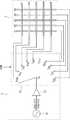
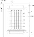
図44は、一般的な抵抗膜式のタッチパネル800の例を示す構成図である。タッチパネル800では、面抵抗が一様な透明抵抗シート801の表面に、多数の点状の突起802が形成されている。透明抵抗シート801と透明電極シート803とは重ねられ、突起802は透明抵抗シート801と透明電極シート803とを電気的に分離するスペーサになっている。透明抵抗シート801の四辺804〜807には、ダイオード群808〜811がそれぞれ接続されている。スイッチ813は、極性切替用の2極双投のスイッチである。スイッチ813のa側が閉成されているときは、電流は電源812の正極からスイッチ813、ダイオード群810、透明抵抗シート801、ダイオード群811、スイッチ813を通って電源12の負極に至るループに流れる。このため、透明抵抗シート801には、辺806、807にほぼ平行な等電位線が生じる。スイッチ813のb側を閉成すると、電流は電源812の正極からスイッチ813、ダイオード群808、透明抵抗シート801、ダイオード群809、スイッチ813を通って電源12の負極に至るループに流れる。このため、透明抵抗シート801には、辺804、805にほぼ平行な等電位線が生じる。透明電極シート803の上から辺814で透明電極シート803上の点815を押下すると、透明抵抗シート801と透明電極シート803とは、点815とこの点に対応した透明抵抗シート801上の点816で接触する。従って、透明電極シート803には、点816の電位が伝達される。点816の電位は、点816の座標に対応しているため、点816の電位を検出回路817により検出すると、押下した点の座標が識別される。点816の電位は、スイッチ813のa側が閉成されているときはy座標、b側が閉成されているときはx座標に対応している。そのため、スイッチ813を切り替えることにより、点815のx、y両座標を識別することができる。 FIG. 44 is a configuration diagram showing an example of a general resistive film
以上のように、抵抗膜式(特許文献1)では、抵抗膜を押下して、抵抗膜を押して変形させる必要がある。そのため、抵抗膜に使用する素材には柔軟な素材が必要となる。よって、タッチパネル表面が傷つきやすく、耐久性が劣る。また、指で抵抗膜の複数個所を押す場合、複数個所のうちで抵抗測定点に近い1箇所を押したときと、測定される抵抗値はほぼ変わらない。そのため、複数の指を同時に検出することはできない。 As described above, in the resistance film type (Patent Document 1), it is necessary to press the resistance film and to deform it by pressing the resistance film. Therefore, a flexible material is required for the material used for the resistance film. Therefore, the touch panel surface is easily damaged and the durability is inferior. Further, when a plurality of locations on the resistance film are pressed with a finger, the measured resistance value is substantially the same as when one location close to the resistance measurement point is pressed among the plurality of locations. Therefore, a plurality of fingers cannot be detected simultaneously.
図45は、一般的な静電容量式のタッチパネルシステム900の例を示す構成図である。図45に示すように、タッチパネルシステム900は、タッチパネル910とタッチパネルコントローラ920とからなる。タッチパネル910は、使用者がタッチ操作を行うことにより信号を入力するセンサ911を備えている。タッチパネルコントローラ920は、センサ911からの信号を受信する入力端子と、入力端子に入力された信号を元に座標値を出力する座標検出手段921と、座標検出手段921からの座標情報を一定間隔で取り込み、表示装置に出力等を行うCPU922とからなる。座標検出手段921は、タッチ操作の感度の変更を行うタッチ操作感度変更手段923を有している。 FIG. 45 is a configuration diagram showing an example of a general electrostatic capacitance type
センサ911は静電容量方式センサであり、使用者がタッチパネル910にタッチ操作した際、センサ911を構成している電極が図45に示すドライブライン−センスライン間の容量値の変化を検出する。 The
タッチパネル910は、M本のドライブラインDLとL本のセンスラインSLとからなり、その交差箇所に静電容量方式によるセンサ911を構成する。タッチ操作の座標検出動作では、ドライブラインDLをスキャンしつつ、タッチ操作によるセンサの容量値の変化をセンスラインSLにて読み取ることにより、タッチ操作された箇所の座標を検出する。この際、検出される容量値の変化値が小さい場合を考慮して、読み取り動作を複数回行い、タッチパネルからの受信信号を上記複数回の読み取り動作に対応させて複数回積算して信号値を増大させる操作が行われている。 The
以上のように、静電容量式(特許文献2)では、膜を変形させる必要がないので、タッチパネル表面に硬い素材を使用できる。そのため、抵抗膜式と比べて、耐久性が高い。また、この方式では、縦横の電極の交差部ごとに容量を測定できるので、タッチパネルの複数の位置に指が接触しても、複数の指のそれぞれの位置を検出できる。 As described above, since the capacitance type (Patent Document 2) does not require deformation of the film, a hard material can be used for the touch panel surface. Therefore, it is more durable than the resistance film type. Further, in this method, the capacitance can be measured for each intersecting portion of the vertical and horizontal electrodes, so that each position of the plurality of fingers can be detected even if the finger touches a plurality of positions on the touch panel.
ところが、発明者は、上述のタッチパネルでの位置検出には、以下に示す問題が有ることを見出した。上述で説明した静電容量式では、縦電極と横電極との間の容量に対して指と電極との間の容量が小さいと、容量測定の精度が低下する。このため、タッチパネルから指が離れると指の位置を検出することができない。例えば、静電容量式では、手袋を装着すると、手袋の厚み分だけ指がタッチパネルから離れるので、指の位置を検出できない。 However, the inventor has found that the position detection using the touch panel has the following problems. In the capacitance type described above, when the capacitance between the finger and the electrode is smaller than the capacitance between the vertical electrode and the horizontal electrode, the accuracy of capacitance measurement is lowered. For this reason, when the finger is removed from the touch panel, the position of the finger cannot be detected. For example, in the capacitance type, when a glove is worn, the finger is separated from the touch panel by the thickness of the glove, so that the position of the finger cannot be detected.
その他の課題と新規な特徴は、本明細書の記述および添付図面から明らかになるであろう。 Other problems and novel features will become apparent from the description of the specification and the accompanying drawings.
一実施の形態によれば、座標入力装置は、交流信号を出力する信号発生部と、前記交流信号に応じた信号を送受信する複数の第1のアンテナを有する第1の送受信部と、第1の送受信部との間で前記信号を送受信する第2のアンテナを有する第2の送受信部と、前記第1の送受信部が前記信号を送受信した際に前記複数の第1のアンテナの位置に対応した前記信号の強度分布を取得し、前記強度分布のピークの位置に応じて検出位置を検出する検出部と、を備えるものである。 According to an embodiment, the coordinate input device includes a signal generation unit that outputs an AC signal, a first transmission / reception unit that includes a plurality of first antennas that transmit and receive a signal corresponding to the AC signal, A second transmitting / receiving unit having a second antenna for transmitting / receiving the signal to / from the transmitting / receiving unit, and a position of the plurality of first antennas when the first transmitting / receiving unit transmits / receives the signal A detection unit that acquires an intensity distribution of the signal and detects a detection position according to a peak position of the intensity distribution.
一実施の形態によれば、座標入力装置は、導電体の位置を検出する座標入力装置であって、交流信号を出力する信号発生部と、前記交流信号に応じた信号を送受信する複数の第1のアンテナを有する第1の送受信部と、第1の送受信部との間で前記信号を送受信する第2のアンテナを有する第2の送受信部と、前記第1の送受信部が前記信号を送受信した際に前記複数の第1のアンテナの位置に対応した前記信号の強度分布を取得し、前記強度分布のピークの位置に応じて、前記第1の送受信部の前記複数の第1のアンテナと前記第2の送受信部の前記1つまたは複数の第2のアンテナとの間に挿入された前記導電体の位置を検出する検出部と、を備えるものである。 According to an embodiment, the coordinate input device is a coordinate input device that detects a position of a conductor, and a signal generator that outputs an AC signal, and a plurality of second transmitters that transmit and receive a signal corresponding to the AC signal. A first transmission / reception unit having one antenna, a second transmission / reception unit having a second antenna for transmitting / receiving the signal between the first transmission / reception unit, and the first transmission / reception unit transmitting / receiving the signal. And obtaining the intensity distribution of the signal corresponding to the position of the plurality of first antennas, and according to the position of the peak of the intensity distribution, the plurality of first antennas of the first transceiver A detection unit that detects a position of the conductor inserted between the one or more second antennas of the second transmission / reception unit.
前記一実施の形態によれば、座標入力装置において、離れた位置の導電体の位置を検出することができる。 According to the one embodiment, in the coordinate input device, the position of the conductor at a distant position can be detected.
以下、図面を参照して本発明の実施の形態について説明する。各図面においては、同一要素には同一の符号が付されており、必要に応じて重複説明は省略される。 Embodiments of the present invention will be described below with reference to the drawings. In the drawings, the same elements are denoted by the same reference numerals, and redundant description is omitted as necessary.
実施の形態1
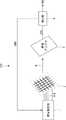
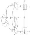
まず、実施の形態1にかかる座標入力装置100について説明する。図1は、実施の形態1にかかる座標入力装置100の構成を模式的に示す図である。座標入力装置100は、信号発生部1、送信アンテナ部2、受信アンテナ3及び検出部4を有する。送信アンテナ部2と受信アンテナ3とは、空間的に離隔して配置される。なお、送信アンテナ部は、単に第1の送受信部とも称する。受信アンテナは、単に第2の送受信部とも称する。
First, the coordinate
信号発生部1は、送信アンテナ部2に交流信号SIGを供給する。送信アンテナ部2は、詳細は後述するが、複数のアンテナ線がメッシュ状に配置される。信号発生部1は、交流信号SIGを、送信アンテナ部2の複数のアンテナ線のいずれか1本に入力する。これにより、送信アンテナ部2の複数のアンテナ線のいずれか1本から、交流信号SIGを伝達する信号である電磁波W(電波)が放射される。なお、アンテナ線は、単にアンテナとも称する。 The
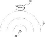
受信アンテナ3は、送信アンテナ部2から放射された信号を受信する。受信アンテナ3は、受信した信号を、受信信号RS1として検出部4に出力する。交流信号SIGを送信する信号である電磁波Wには、受信アンテナ3の大きさ対して十分に長い波長を有する電磁波を用いる。例えば、電磁波Wの波長は、送信アンテナ部2及び受信アンテナ3の大きさの10倍以上であることが望ましい。つまり、受信アンテナ3の共振周波数よりも低い周波数を有する電磁波を使用する。例えば、周波数が1〜10MHz程度の電磁波の場合、波長は300〜30mとなる。このため、一般的な10インチ程度の大きさの携帯端末は、電磁波の波長に比べて十分小さい。この場合、電磁波による信号の伝送は、通常の無線で用いられる遠方界ではなく、近傍界の電磁波によって行われる。近傍界での通信は、遠方界での通信よりも信号強度の距離依存が大きいので、距離判定を容易に行うことができる。 The
検出部4は、信号発生部1に制御信号CON1を出力し、信号発生部1が送信アンテナ部2のいずれのアンテナ線に交流信号SIGを供給するかを制御する。そして、検出部4は、受信アンテナ3が受信した信号の強度を検出し、各アンテナ線と受信信号の強度とを関連付ける。検出部4は、制御信号CON1により、所定の時間間隔で交流信号SIGが供給されるアンテナ線を切り替えることで、送信アンテナ部2のそれぞれについて受信信号の強度を検出することができる。 The
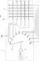
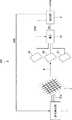
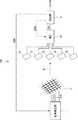
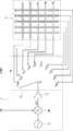
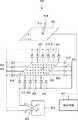
信号発生部1及び送信アンテナ部2について、詳細に説明する。図2は、信号発生部1及び送信アンテナ部2の構成を模式的に示す図である。信号発生部1は、信号発振部11、増幅器12及びマルチプレクサ(multiplexer、以下MUXと表記する)13を有する。信号発振部11は、交流信号SIGを発振し、増幅器12へ入力する。増幅器は、交流信号SIGを増幅して、MUX13へ出力する。 The
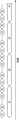
送信アンテナ部2は、Y方向に延伸するアンテナ線X1〜X5、X方向に延伸するアンテナ線Y1〜Y5により構成される。図2では、X方向とY方向とは互いに直交する。アンテナ線X1〜X5は、アンテナ線Y1〜Y5の下方に配置される。図2では、X方向のアンテナ線及びY方向のアンテナ線が5本の場合について示しているが、これは例示に過ぎない。X方向及びY方向のアンテナ線は任意の複数本設けることができ、X方向のアンテナ線とY方向のアンテナ線とは、異なる本数であってもよいし、同じ本数であってもよい。また、Y方向のアンテナ線は、X方向のアンテナ線の下方に配置されてもよいし、上方に配置されてもよい。 The
MUX13は、端子TX1〜TX5、端子TY1〜TY5、端子Tsを有する。端子Tsは、増幅器12の出力端子と接続される。マルチプレクサの端子TX1〜TX5、TY1〜TY5は、それぞれアンテナ線X1〜X5、アンテナ線Y1〜Y5と接続される。MUX13は、検出部4からの制御信号CON1に応じて、端子Tsを端子TX1〜TX5、TY1〜TY5のいずれかに接続する。The
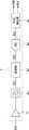
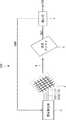
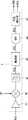
検出部4について、詳細に説明する。図3は、検出部4の構成を模式的に示すブロック図である。検出部4は、増幅器41、フィルタ42、検波部43、A/Dコンバータ44及び位置検出部45を有する。増幅器41は、受信アンテナ3からの受信信号RS1を増幅し、フィルタ42へ出力する。フィルタ42は、受信信号RS1からノイズ等の不要な周波数成分を除去した受信信号RS2を、検波部43へ出力する。検波部43は、受信信号RS2の交流信号の特定周波数成分が持つ振幅や周波数偏移、位相偏移を検出して、それに対応する電圧をA/Dコンバータ44へ出力する。A/Dコンバータ44は、アナログ信号である受信信号RS3をA/D変換し、デジタル信号である受信信号RSdを位置検出部45へ出力する。これにより、受信信号の強度は数値化され、位置検出部45により受信信号の強度を定量的に評価することができる。換言すれば、受信アンテナ3が受信した電磁波Wを電圧や電流などの受信信号に変換することで、電磁波Wの強度を検出することができる。位置検出部45は、制御信号CON1で電磁波Wを送信するアンテナ線を選択するとともに、そのときの受信信号の強度を検出てアンテナ線と関連づけることができる。位置検出部45で検出された位置情報POSは、適宜外部のコンピュータ等に出力される。 The
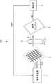
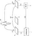
座標入力装置100では、送信アンテナ部2と受信アンテナ3との間で交流信号SIGが電磁波Wにより空間伝送される。この際、送信アンテナ部2と受信アンテナ3との間に導体が挿入されると、受信アンテナ3で受信する信号の強度が変化する。図4は、送信アンテナ部2と受信アンテナ3との間に導電体が挿入される場合の座標入力装置100の構成を模式的に示す図である。図4では、導体の一例として、座標入力装置100のユーザの指10が挿入される例を示している。送信アンテナ部2と受信アンテナ3との間に指10が挿入されると、指10が挿入されない場合と比べて、信号の強度が変化する。よって、検出部4により信号強度の変化を検出することで、送信アンテナ部2と受信アンテナ3との間の指10の有無を検出することができる。これにより、検出部4は、送信アンテナ部2に対する指10の位置を検出することができる。 In the coordinate
図1及び図4では、送信アンテナ2及び受信アンテナ3について説明したが、送信アンテナ2を受信アンテナとして用い、受信アンテナを送信アンテナとして用いることも可能である。この場合、図2に示す端子TSに、信号発振部11及び増幅器12の代わりに、図3に示す検出部4が接続される。また、受信アンテナ3に、信号発振部11及び増幅器12が接続される。また、図2において、アンテナ線は直行するX方向とY方向の2組となっているが、これは例示に過ぎない。例えば、X方向及びY方向に直交するZ方向などの異なる方向のアンテナ線の組を配置することもできる。 1 and 4, the
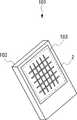
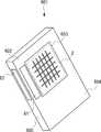
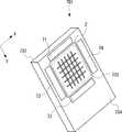
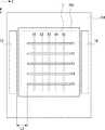
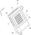
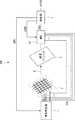
次いで、座標入力装置100の実装態様について説明する。図5は、座標入力装置100を実装したタッチパネルが搭載される携帯端末101をタッチパネル側(表側)から見た場合の一例を示す斜視図である。携帯端末101は、例えばスマートフォンである。携帯端末101の筐体102の表側には、タッチパネル103が搭載される。送信アンテナ部2はタッチパネル103に組み込まれる。送信アンテナ部2に設けられたメッシュ状の複数のアンテナ線は、座標入力装置100の送信アンテナとして機能するとともに、いわゆる静電容量式のタッチパネル103の電極としても機能する。 Next, an implementation mode of the coordinate
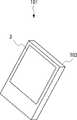
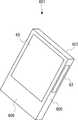
図6は、座標入力装置100を実装したタッチパネルが搭載される携帯端末101をタッチパネル側(表側)とは反対の側(裏側)から見た場合の一例を示す斜視図である。携帯端末101の筐体102の裏側には、受信アンテナ3が配置される。受信アンテナ3は、筐体102の外側に配置されてもよいし、筐体102の内側に配置されてもよい。すなわち、受信アンテナ3には、指が接触してもよいし、指が接触しなくてもよい。以下、この例に限らず、受信アンテナには、指が接触してもよいし、指が接触しなくてもよい。信号発生部1及び検出部4は、携帯端末101の筐体102の内部に配置される。 FIG. 6 is a perspective view showing an example when the
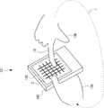
上述のように、座標入力装置100が携帯端末101に組み込まれる場合、携帯端末101のユーザは、指でタッチパネル103に触れることで、携帯端末101を操作する。図7は、携帯端末101のユーザが携帯端末101を保持する場合の例を示す図である。図7に示すように、ユーザは例えば左手10aで携帯端末101を保持する。この際、左手10aの一部の指が携帯端末101の裏側(受信アンテナ3側)に接触する。また、携帯端末101を操作するため、ユーザは、左手10aの指の一部又は右手10bの指10をタッチパネルの上方で動かす。左手10aの指の一部を動かす場合には、タッチパネル103上方の指から受信アンテナ3側の指を通って、電磁波Wが伝達される。指10を動かす場合には、指10から人体(図7に示す経路L)を経由して、左手10aの指を通って、電磁波Wが伝達される。 As described above, when the coordinate
一方、ユーザの指は、座標入力装置100にとっては導電体の一種として作用する。この際、ユーザの指がタッチパネル103に接しているか、又は離れているかに関わりなく、座標入力装置100が機能することにより、送信アンテナ部2に対する指の位置を検出することができる。ユーザの指がタッチパネル103から離れている場合に座標入力装置100が指の位置を検出する原理については、後述する。 On the other hand, the user's finger acts as a kind of conductor for the coordinate
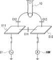
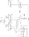
次いで、静電容量式のタッチパネルの位置検出と座標入力装置100の位置検出との相違について説明する。まず、静電容量式のタッチパネルの位置検出方法について説明する。図8は、静電容量式のタッチパネル103の位置検出の概要を示す回路構成図である。図8では、電極E11及びE12、信号発生部1及び電流計AMMを有する。電極E11は、送信アンテナ部2のアンテナ線X1〜X5のいずれかに対応する。電極E12は、送信アンテナ部2のアンテナ線Y1〜Y5のいずれかに対応する。 Next, the difference between the position detection of the capacitive touch panel and the position detection of the coordinate
電極E11には、発振器S1から信号が入力される。電極E12には電流計AMMが接続される。電極E11と電極E12との間には、容量C11が生じる。発振器S1から電極E11に信号が入力された状態で、電極E11及びE12に指10が近づくと、電極E11と指との間に容量C12が生じ、電極E12と指との間に容量C13が生じる。 A signal is input to the electrode E11 from the oscillator S1. An ammeter AMM is connected to the electrode E12. A capacitance C11 is generated between the electrode E11 and the electrode E12. When the
容量C11、C12及びC13による合成容量Ct1は、以下の式(1)で表される。
電極E11及びE12から指10が遠ざかると、容量C11に比べて容量C12及びC13は小さくなるので、指10の位置の変化に対する容量検出の感度が低下する。つまり、静電容量式では、電極E11及びE12から指10が離れてしまうと、指10の位置が検出できない。このため、多くの静電容量式のタッチパネルは、タッチパネルに指が接触している必要が有る。静電容量式のタッチパネルから指が遠ざかった時の感度を高めるには、電極E11と電極E12との間の距離を大きくして容量C11を小さくすればよい。しかし、この場合には、電極E11と電極E12との間の間隔が広がるので、位置検出の分解能が低下してしまう。 When the
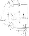
次いで、座標入力装置100の位置検出について説明する。図9は、座標入力装置100の位置検出の概要を示す回路構成図である。図9では、簡略化のため、送信アンテナ部2のアンテナ線の内、アンテナ線X1及びX2のみを図示している。アンテナ線X1及びX2のそれぞれには、信号発生部1から交流信号SIGが選択的に入力される。この例では、説明の簡略化のため、アンテナ線X1に交流信号SIGが入力される場合について説明するが、交流信号SIGが供給されるアンテナ線をアンテナ線X1に限定するものではない。アンテナ線X1とアンテナ線X2との間には、容量C21が生じる。信号発生部1からアンテナ線X1に信号が入力された状態で、アンテナ線X1と受信アンテナ3との間に指10及び指11が挿入されると、アンテナ線X1と指10との間に容量C22が生じ、指10と受信アンテナ3との間に容量C23が生じる。また、アンテナ線X1と受信アンテナ3との間に容量C24が存在する。ここで、指10と指11とは電気的に接続されている指であればよく、同じ指でも別の指でも良い。指10はアンテナ線X1の近傍にあり、指11は受信アンテナ3の近傍にあるものとする。 Next, position detection of the coordinate
この位置検出方式では、送信アンテナ部2からの信号を、指10及び指11を介して受信アンテナに送っている。この方式では、電磁波の波長に対して十分短い距離(送信アンテナ部2と受信アンテナ3との間の距離)で、電磁波を用いた信号伝達を行う。このため、電磁波による信号伝達よりも、電界による信号伝達が支配的となる。そのため、図9では、アンテナ線X1、指10、指11及び受信アンテナ3のそれぞれの間に働く相互作用を容量で表している。信号発生部1からアンテナ線X2へは交流信号は供給されないので、アンテナ線X1とアンテナ線X2との間の容量は影響しない。 In this position detection method, a signal from the
ここで、検出部4の入力インピーダンスをZin、電磁波の周波数をfとすると、アンテナ線X1での送信信号の振幅Vtxと受信アンテナ3での受信信号の振幅Vrxとの比は、以下の式(2)で表される。ここで、指10はアンテナ線X1の近傍に、指11は受信アンテナ3の近傍にあるので、C24<<C22、かつ、C24<<C23となる。このため、容量C24は無視できる。
式(2)に示すように、送信信号の振幅と受信信号の振幅との比(Vrx/Vtx)は、容量C21には依存しない。また、入力インピーダンスZinを1/(2πfC22)及び1/(2πfC23)に近い値に設定することで、受信信号の振幅と送信信号の振幅との比(Vrx/Vtx)を大きな値とすることができる。As shown in Expression (2), the ratio (Vrx / Vtx ) between the amplitude of the transmission signal and the amplitude of the reception signal does not depend on the capacitance C21. Also, by setting the input impedance Zin to a value close to 1 / (2πfC22) and 1 / (2πfC23), the ratio (Vrx / Vtx ) between the amplitude of the received signal and the amplitude of the transmitted signal is set to a large value. can do.
式(2)に示すように、検出部4は、容量ではなく交流信号の振幅を検出するので、例えばフィルタ回路(図3のフィルタ42)などを用いることで特定の周波数の信号を取り出すことができる。このため、ノイズ耐性を向上させることが可能である。また、容量C21に対する依存性がないため、アンテナ線X1とアンテナ線X2との間の距離を狭くしても、検出感度を低下させることなく、位置検出の分解能を高めることができる。 As shown in Expression (2), the
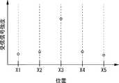
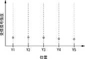
送信アンテナ部2から離れた位置に、例えば指10が静止している状態で、検出部4は、アンテナ線X1〜X5のそれぞれについて受信信号の強度を検出する。これにより、受信信号の強度のX方向の位置依存性を示す分布が得られる。また、検出部4は、アンテナ線Y1〜Y5のそれぞれについて受信信号の強度を検出する。これにより、受信信号の強度のY方向の位置依存性を示す分布が得られる。以上より、受信信号の強度のXY平面での分布が得られることが理解できる。図10は、アンテナ線X1〜X5にかかる受信信号の強度を示す図である。図11は、アンテナ線Y1〜Y5にかかる受信信号の強度を示す図である。この例では、X方向についてはアンテナ線X3から信号を送信した場合の受信信号の強度が最も大きく、Y方向についてはアンテナ線Y2から信号を送信した場合の受信信号の強度が最も大きい。これにより、この例では、アンテナ線X3とアンテナ線Y2とが交差する位置の近傍に指10が存在することを検出できる。 For example, in a state where the
このように、X方向とY方向のそれぞれについて受信信号が最大となるアンテナ線を特定することで、送信アンテナ部2に対する指(導体)の位置を検出できることが理解できる。 Thus, it can be understood that the position of the finger (conductor) with respect to the
次いで、座標入力装置100における位置検出の距離依存性について説明する。前述したように、座標入力装置100では、電磁波による信号の伝送は、通常の無線で用いられる遠方界ではなく、近傍界の電磁波によって行われる。近傍界での通信は、遠方界での通信よりも信号強度の距離依存が大きいので、距離判定を容易に行うことができる。 Next, distance dependency of position detection in the coordinate
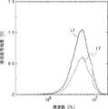
図12は、座標入力装置100における位置検出の距離依存性を示すグラフである。図12において、横軸は交流信号の周波数であり、縦軸は検出部4が検出する受信信号の強度(電圧)を示す。図12では、指がタッチパネル103に接している場合の受信信号強度をL1(実線)で、指がタッチパネル103から5mm程度離れている場合の受信信号強度をL2(破線)で示している。 FIG. 12 is a graph showing the distance dependency of position detection in the coordinate
図12に示すように、受信信号の強度は、指がタッチパネル103から遠ざかるにつれて弱くなる。したがって、検出部4は、受信信号のピークの強度を測定することで、検出した指がタッチパネル103からどの程度離れているかを検出することも可能である。 As shown in FIG. 12, the intensity of the received signal becomes weaker as the finger moves away from the
なお、上述では、1か所の位置検出のみを行う場合について説明したが、これは例示に過ぎない。例えば、受信信号の2番目に大きなピーク、3番目に大きなピークなど、複数のピークを検出することで、複数本の指の位置を検出できることはいうまでもない。 In the above description, the case where only one position is detected has been described, but this is merely an example. For example, it is needless to say that the positions of a plurality of fingers can be detected by detecting a plurality of peaks such as the second largest peak and the third largest peak of the received signal.
本構成では、第1の送受信部と第2の送受信部との間で電磁波を伝送する。そして、第1の送受信部と第2の送受信部との間に挿入される導電体による受信信号の強度変化を、第1の送受信部又は第2の送受信部に設けた複数のアンテナの位置に結び付けることで、信号強度のピーク位置を検出する。これにより、第1の送受信部又は第2の送受信部が設けられた面における導電体の2次元的位置を特定できる。更に、信号強度を評価することで、第1の送受信部又は第2の送受信部が設けられた面に対する導電体の距離を検出することが可能である。したがって、本構成によれば、第1の送受信部と第2の送受信部との間に挿入された導電体の3次元的位置を特定することも可能である。 In this configuration, electromagnetic waves are transmitted between the first transmission / reception unit and the second transmission / reception unit. And the intensity | strength change of the received signal by the conductor inserted between the 1st transmission / reception part and the 2nd transmission / reception part is made into the position of the some antenna provided in the 1st transmission / reception part or the 2nd transmission / reception part. By linking, the peak position of the signal intensity is detected. Thereby, the two-dimensional position of the conductor in the surface in which the 1st transmission / reception part or the 2nd transmission / reception part was provided can be pinpointed. Furthermore, by evaluating the signal strength, it is possible to detect the distance of the conductor to the surface on which the first transmission / reception unit or the second transmission / reception unit is provided. Therefore, according to this structure, it is also possible to specify the three-dimensional position of the conductor inserted between the first transmission / reception unit and the second transmission / reception unit.
その結果、本構成では、導電体が第1の送受信部及び第2の送受信部に接触しているか否かにかかわらず、導電体の位置を検出することが可能となる。その結果、静電容量方式のタッチパネルのように、指がタッチパネルに接触していない場合に、指の位置を検出することができないという課題を解決することができる。 As a result, in this configuration, the position of the conductor can be detected regardless of whether the conductor is in contact with the first transmission / reception unit and the second transmission / reception unit. As a result, it is possible to solve the problem that the position of the finger cannot be detected when the finger is not in contact with the touch panel as in the capacitive touch panel.
なお、上述では、第1の送受信部から信号を送信し、第2の送受信部が信号を受信するものとして説明した。しかし、第2の送受信部から信号を送信し、第1の送受信部が信号を受信する構成とすることもできる。この場合、信号発生部1を第2の送受信部に接続し、検出部4を第1の送受信部に接続すればよい。 In the above description, the signal is transmitted from the first transmission / reception unit, and the second transmission / reception unit receives the signal. However, it is also possible to adopt a configuration in which a signal is transmitted from the second transmission / reception unit, and the first transmission / reception unit receives the signal. In this case, the
実施の形態2
次に、実施の形態2にかかる座標入力装置について説明する。本実施の形態では、座標入力装置100の検出部4の位置検出部45における位置検出方法の変形例について説明する。
Next, a coordinate input device according to the second embodiment will be described. In the present embodiment, a modified example of the position detection method in the
実施の形態1では、位置検出部45が、X方向とY方向について、受信信号の強度が最大のアンテナ線を特定することで、指の位置を検出する方法について説明した。しかし、この方法だと、位置検出の分解能はアンテナ線の配置ピッチに制限されてしまう。本実施の形態では、アンテナ線の配置ピッチを狭めることなく、位置検出の分解能を高める方法について説明する。 In the first embodiment, the method has been described in which the
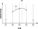
図13は、実施の形態2におけるアンテナ線X1〜X5にかかる受信信号の強度を示す図である。図13に示すように、位置検出部45は、アンテナ線X1〜X5の受信信号の強度のデータに最も近似する多項式F1を生成する。そして、位置検出部45は、多項式F1のピークのX座標XPを検出する。同様に、アンテナ線Y1〜Y5に対応する受信信号の強度についても同様の多項式近似を行い、多項式のピークのY座標YPを検出する。これにより、位置検出部45は、座標(XP、YP)を指の位置として検出することができる。 FIG. 13 is a diagram illustrating the strength of the reception signal applied to the antenna lines X1 to X5 in the second embodiment. As illustrated in FIG. 13, the
本実施の形態では、各アンテナ線間を多項式で内挿することで、位置検出の分解能をアンテナ線の配置ピッチよりも小さくすることができる。これにより、実施の形態1と比べて、より位置検出の分解能が優れた座標入力装置を実現できる。 In the present embodiment, by interpolating between the antenna lines with a polynomial, the position detection resolution can be made smaller than the arrangement pitch of the antenna lines. Thereby, it is possible to realize a coordinate input device having a better position detection resolution than that of the first embodiment.
実施の形態3
次に、実施の形態3にかかる座標入力装置について説明する。本実施の形態では、座標入力装置100の検出部4の位置検出部45における位置検出方法の変形例について説明する。
Next, a coordinate input apparatus according to the third embodiment will be described. In the present embodiment, a modified example of the position detection method in the
実施の形態1では、位置検出部45が、X方向とY方向について、受信信号の強度が最大のアンテナ線を特定することで、指の位置を検出する方法について説明した。しかし、この方法だと、位置検出の分解能はアンテナ線の配置ピッチに制限されてしまう。本実施の形態では、アンテナ線の配置ピッチを狭めることなく、位置検出の分解能を高める方法について説明する。 In the first embodiment, the method has been described in which the
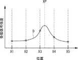
図14は、実施の形態3におけるアンテナ線X1〜X5にかかる受信信号の強度を示す図である。位置検出部45は、受信信号の予想分布が予め記憶されており、この分布をデータと照合することで、指の位置を検出する。図14に示すように、位置検出部45は、アンテナ線X1〜X5の受信信号の強度のデータに、予想分布Dを当てはめる。この際、アンテナ線X1〜X5の受信信号の強度のデータと予想分布Dとの相関が最大となるように、当てはめを行う。そして、位置検出部45は、予想分布DのピークのX座標XPを検出する。同様に、アンテナ線Y1〜Y5に対応する受信信号の強度についても同様に予想分布を当てはめ、予想分布のピークのY座標YPを検出する。この際、アンテナ線Y1〜Y5の受信信号の強度のデータと予想分布との相関が最大となるように、当てはめを行う。これにより、位置検出部45は、座標(XP、YP)を指の位置として検出することができる。 FIG. 14 is a diagram illustrating the strength of the reception signal applied to the antenna lines X1 to X5 in the third embodiment. The
本実施の形態では、各アンテナ線に対応する受信信号強度に予想分布を当てはめることで、位置検出の分解能をアンテナ線の配置ピッチよりも小さくすることができる。これにより、実施の形態1と比べて、より位置検出の分解能が優れた座標入力装置を実現できる。 In the present embodiment, by applying an expected distribution to the received signal intensity corresponding to each antenna line, the position detection resolution can be made smaller than the arrangement pitch of the antenna lines. Thereby, it is possible to realize a coordinate input device having a better position detection resolution than that of the first embodiment.
実施の形態4
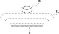
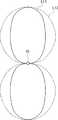
次に、実施の形態4にかかる座標入力装置について説明する。本実施の形態では、送信アンテナ部2のアンテナ線及び受信アンテナ3の形状の影響について説明する。図15は、線状の送信アンテナ部2のアンテナ線X1の断面における電界を模式的に示す図である。なお、アンテナ線X1は代表例に過ぎず、アンテナ線X2〜X5、Y1〜Y5も同様の電界を形成する。図16は、平面状の受信アンテナ3の断面における電界を模式的に示す図である。図15及び図16には、それぞれ等電位線ELを表示している。受信アンテナ3は平面状であるので、指10が受信アンテナ3近傍にある場合、伝送される信号の強度は距離の1乗分の1で変化する。これに対し、アンテナ線X1は線状であるので、指10が受信アンテナ近傍にある場合、伝送される信号の強度は距離の2乗分の1で変化する。すなわち、線状のアンテナ線X1は信号強度の距離依存性が大きく、平面状の受信アンテナ3は距離依存性が小さい。
Next, a coordinate input device according to the fourth embodiment will be described. In the present embodiment, the influence of the antenna line of the transmitting
つまり、送信アンテナ部2のアンテナ線を線状とし、受信アンテナ3を平面状とすることで、信号強度に対する受信アンテナ3と人体との距離の依存性を小さくすることができる。これにより、送信アンテナ部2のアンテナ線と指10との間の距離を、高い精度で検出することができる。 That is, the dependence of the distance between the receiving
実施の形態5
次に、実施の形態5にかかる座標入力装置500について説明する。座標入力装置500は、実施の形態1にかかる座標入力装置100の変形例である。図17は、実施の形態5にかかる座標入力装置500の構成を模式的に示す図である。座標入力装置500は、座標入力装置100の信号発生部1を、信号発生部5に置換した構成を有する。座標入力装置500のその他の構成は、座標入力装置100と同様である。
Next, a coordinate
図18は、信号発生部5及び送信アンテナ部2の構成を模式的に示す図である。信号発生部5は、信号発生部1の信号発振部11を信号発振部51に置換した構成を有する。信号発振部51は、検出部4からの制御信号CON1に応じて、周波数が異なる交流信号を出力する。この例では、信号発振部51が周波数f1の交流信号SIG1又は周波数f2の交流信号SIG2を出力する例を図示している。図面の簡略化のため、図18では、MUX13の内部構造の表示を省略している。例えば、周波数f1を1MHz〜10MHz、周波数f2を10kHz〜1MHzに設定することができる。なお、信号発振部が出力する信号の周波数は2通りではなく、3通り以上でもよい。 FIG. 18 is a diagram schematically illustrating the configuration of the
一般に、電磁波の周波数が高いほど、アンテナの指向性は強くなる。図19は、アンテナ線X1を断面方向から見た場合の電磁波の広がりを模式的に示す図である。図9では、電磁波の周波数が高い場合の電界の広がりを実線L11、電磁波の周波数が低い場合の電界の広がりを破線L12で表示している。なお、アンテナ線X1は代表例に過ぎず、アンテナ線X2〜X5、Y1〜Y5でもアンテナ線X1と同様である。低周波数の信号を用いると、得られる信号強度の指の位置に対する依存性は小さくなり、アンテナ間での信号強度の差は小さくなる。一方、高周波数の信号を用いると、得られる信号強度の指の位置に対する依存性が大きくなり、アンテナ間での信号強度の差は大きくなる。 In general, the higher the frequency of electromagnetic waves, the stronger the directivity of the antenna. FIG. 19 is a diagram schematically illustrating the spread of electromagnetic waves when the antenna wire X1 is viewed from the cross-sectional direction. In FIG. 9, the spread of the electric field when the frequency of the electromagnetic wave is high is indicated by a solid line L11, and the spread of the electric field when the frequency of the electromagnetic wave is low is indicated by a broken line L12. The antenna line X1 is only a representative example, and the antenna lines X2 to X5 and Y1 to Y5 are the same as the antenna line X1. When a low-frequency signal is used, the dependency of the obtained signal strength on the finger position is reduced, and the difference in signal strength between antennas is reduced. On the other hand, when a high-frequency signal is used, the dependence of the obtained signal strength on the finger position increases, and the difference in signal strength between antennas increases.
電磁波の周波数の相違による影響を利用すれば、以下のような位置検出を実現できる。まず、低周波数の信号の強度を測定し、指と送信アンテナ部2との間の距離を推定する。低周波数の信号を用いる場合のアンテナの指向性は弱いので、送信アンテナ部2の主面に平行な方向の位置依存性が小さくなる。その結果、送信アンテナ部2の主面に垂直な方向に対する距離の測定精度が向上する。 The following position detection can be realized by utilizing the influence of the difference in frequency of electromagnetic waves. First, the intensity of the low frequency signal is measured, and the distance between the finger and the transmitting
次に、高周波数の信号を用いるとアンテナの指向性が強いので、アンテナ間での信号強度の差が大きくなる。よって、送信アンテナ部2の主面に平行な方向の位置依存性が大きくなる。その結果、送信アンテナ部2の主面に平行な方向での指の位置の検出精度が高くなる。 Next, when a high-frequency signal is used, the directivity of the antenna is strong, so that the difference in signal strength between the antennas increases. Therefore, the position dependency in the direction parallel to the main surface of the transmitting
以上のように、交流信号の周波数を時間的に変化させることで、送信アンテナ部2の主面に垂直な方向に対する距離の測定精度と、送信アンテナ部2の主面に平行な方向での指の位置の検出精度の双方を向上させることができる。 As described above, by changing the frequency of the AC signal with time, the measurement accuracy of the distance with respect to the direction perpendicular to the main surface of the
実施の形態6
次に、実施の形態6にかかる座標入力装置600について説明する。座標入力装置600は、実施の形態1にかかる座標入力装置100の変形例である。図20は、実施の形態6にかかる座標入力装置600の構成を模式的に示す図である。座標入力装置600は、受信アンテナを複数有する。図20は、座標入力装置600が受信アンテナ61〜63を有する例を図示している。そして、受信アンテナ61〜63は、マルチプレクサ(MUX)60により、検出部4と択一的に接続される。なお、検出部4は、制御信号CON2により、検出部4に受信アンテナ61〜63のいずれを接続するかを制御することができる。Embodiment 6
Next, a coordinate
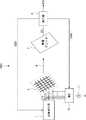
次いで、受信アンテナ61〜63の配置態様について説明する。図21は、座標入力装置600を実装したタッチパネルが搭載される携帯端末601をタッチパネル側(表側)から見た場合の一例を示す斜視図である。携帯端末601は、筐体602の表面604に、タッチパネル603が設けられている。タッチパネル603には、送信アンテナ部2が組み込まれている。この例では、受信アンテナ61は、表面604のタッチパネル603の外周部に配置される。受信アンテナ62は、携帯端末601の側面605に配置される。 Next, an arrangement mode of the receiving
図22は、座標入力装置600を実装したタッチパネルが搭載される携帯端末601をタッチパネル側(表側)とは反対の側(裏側)から見た場合の一例を示す斜視図である。受信アンテナ63は、携帯端末601の裏面606に配置される。 FIG. 22 is a perspective view showing an example when the
裏面606に配置された受信アンテナ63は、携帯端末601を手に持っている時は効率的に電磁波を受信できる。しかし、裏面を下にして携帯端末601を机の上に置くと裏面606は隠れてしまうので、受信アンテナ63は電磁波を受信しにくくなる。ところが、表面604の受信アンテナ61と側面605の受信アンテナ62とは露出しているので、電磁波を受信しやすい。このように、受信感度が最適となる受信アンテナは、座標入力装置を組み込んだ携帯端末の使い方によって変化する。よって、携帯端末601のように、複数の受信アンテナを異なる面に配置することで、座標入力装置を組み込んだ端末の使い方による受信感度の変化に対応することができる。 The receiving
また、受信アンテナ61〜63の切り替えは、順番に行うことができる。図23は、受信アンテナ61〜63の切り替えタイミングを示す図である。送信アンテナ部2のアンテナ線は10本あるので、10本のアンテナ線に対応する受信強度を測定するごとに、用いる受信アンテナを切り替えることができる。そして、受信アンテナ61〜63のうち、受信強度が最適となるようなもの、例えばもっとも各アンテナ線に対応する平均的な受信強度が最も強くなる受信アンテナを決定する。そして、決定した受信アンテナで受信した信号強度を用いて、指の位置検出を行えばよい。 In addition, switching of the receiving
上述の受信アンテナの切り替えは継続的に行ってもよいし、最適な受信アンテナを決定したのちは受信アンテナの切り替えを中止し、決定した受信アンテナを継続して用いてもよい。 The above-described reception antenna switching may be performed continuously, or after the optimal reception antenna is determined, the reception antenna switching may be stopped and the determined reception antenna may be used continuously.
なお、本実施の形態では、受信アンテナが3つの場合について説明したが、受信アンテナは2又は4以上であってもよい。 In the present embodiment, the case where there are three reception antennas has been described, but the number of reception antennas may be two or four or more.
実施の形態7
次に、実施の形態7にかかる座標入力装置700について説明する。座標入力装置700は、実施の形態6にかかる座標入力装置600の変形例である。図24は、実施の形態7にかかる座標入力装置700の構成を模式的に示す図である。座標入力装置700は、座標入力装置600と同様に、受信アンテナを複数有する。図24は、座標入力装置700が受信アンテナ71〜75を有する例を図示している。受信アンテナ71〜75は、マルチプレクサ(MUX)70により、検出部4と択一的に接続される。なお、検出部4は、制御信号CON3により、検出部4に受信アンテナ71〜75のいずれを接続するかを制御することができる。
Next, a coordinate
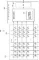
次いで、受信アンテナ71〜75の配置態様について説明する。図25は、座標入力装置700を実装したタッチパネルが搭載される携帯端末701をタッチパネル側(表側)から見た場合の一例を示す斜視図である。携帯端末701は、筐体702の表面704に、タッチパネル703が設けられている。タッチパネル703には、送信アンテナ部2が組み込まれている。この例では、受信アンテナ71〜74は、表面604のタッチパネル603の外周部に配置される。なお、受信アンテナ75は、受信アンテナ63と同様の位置に配置されるため、詳細な説明を省略する。 Next, an arrangement mode of the receiving
図25に示すように、携帯端末701の表面704の中央部には、タッチパネル703が配置される。受信アンテナ71〜74は、表面704表面のタッチパネル703の周辺部に配置される。受信アンテナ71及び72は、X方向を長手方向とする帯状のアンテナである。図26は、受信アンテナ71及び72とアンテナ線との対応関係を示す図である。受信アンテナ71及び72は、送信アンテナ部2のアンテナ線X1〜X5から電磁波が放射される際の受信に用いられる。 As illustrated in FIG. 25, a
受信アンテナ71及び72は、送信アンテナ部2を挟んで対向配置される。受信アンテナ73及び74は、Y方向を長手方向とする帯状のアンテナである。受信アンテナ73及び74は、送信アンテナ部2を挟んで対向配置される。図27は、受信アンテナ73及び74とアンテナ線との対応関係を示す図である。受信アンテナ73及び74は、送信アンテナ部2のアンテナ線Y1〜Y5から電磁波が放射される際の受信に用いられる。 The receiving
携帯端末701では、受信アンテナと各アンテナ線との距離が等しくなる。具体的には、受信アンテナ71とアンテナ線X1〜X5との間の距離は、Lxに統一されている。また、図には記載していないが、受信アンテナ72とアンテナ線X1〜X5との間の距離は、Lxbに統一されている。ここで、LxとLxbとは同一でもよいし、異なっていてもよい。受信アンテナ73及び74とアンテナ線Y1〜Y5との間の距離は、Lyに統一されている。また、図には記載していないが、受信アンテナ74とアンテナ線Y1〜Y5との間の距離は、Lybに統一されている。ここで、LyとLybとは同一でもよいし、異なっていてもよい。これにより、指がパネルに接近していないときに各送信アンテナから受信アンテナに伝わる信号強度が均一となるので、指の位置の検出精度を高めることができる。 In the
上述では、受信アンテナ71及び72を有する例について説明したが、これは例示にすぎず、受信アンテナ71及び72のいずれか一方のみを配置してもよい。また、受信アンテナ73及び74を有する例について説明したが、これは例示にすぎず、受信アンテナ73及び74のいずれか一方のみを配置してもよい。 In the above description, the example having the
さらに、受信アンテナを配置する位置は、タッチパネルが配置された表面に限られない。以下では、座標入力装置700の変形例について説明する。図28は、座標入力装置700の変形例である座標入力装置を実装したタッチパネルが搭載される携帯端末707をタッチパネル側(表側)から見た場合の一例を示す斜視図である。図28では、携帯端末707の側面708にX方向を長手方向とする受信アンテナ76が配置され、側面705にY方向を長手方向とする受信アンテナ77が配置される。 Furthermore, the position where the receiving antenna is disposed is not limited to the surface where the touch panel is disposed. Below, the modification of the coordinate
携帯端末707の側面708はY方向に垂直な面である。X方向を長手方向とする受信アンテナ76は、側面708上に配置される。よって、受信アンテナ76とアンテナ線X1〜X5との間の距離は、Lxに統一される。 A
携帯端末707の側面705はX方向に垂直な面である。Y方向を長手方向とする受信アンテナ77は、側面705上に配置される。よって、受信アンテナ77とアンテナ線Y1〜Y5との間の距離は、Lyに統一される。 A
したがって、携帯端末707では、携帯端末701と同様に、受信アンテナと各アンテナ線との距離が等しくなる。これにより、指がパネルに接近していないときに各送信アンテナから受信アンテナに伝わる信号強度が均一となるので、指の位置の検出精度を高めることができる。 Therefore, in the
なお、本実施の形態では、受信アンテナが5つの場合について説明したが、受信アンテナは2〜4又は6以上であってもよい。 In addition, although this embodiment demonstrated the case where the number of receiving antennas was five, 2-4 or 6 or more receiving antennas may be sufficient.
実施の形態8
次に、実施の形態8にかかる座標入力装置について説明する。本実施の形態では、座標入力装置100の検出部4の位置検出部45において、誤検出を防止する方法について説明する。
Next, a coordinate input device according to an eighth embodiment will be described. In the present embodiment, a method for preventing erroneous detection in the
図29は、実施の形態8におけるアンテナ線X1〜X5かかる受信信号の強度を示す図である。この例では、アンテナ線X3を用いた場合の信号強度が最大となっている。図30は、実施の形態8におけるアンテナ線Y1〜Y5にかかる受信信号の強度を示す図である。この例では、アンテナ線Y1〜Y5のそれぞれで、信号強度はほぼ等しい低い値となっている。 FIG. 29 is a diagram illustrating the strength of the reception signal of the antenna lines X1 to X5 according to the eighth embodiment. In this example, the signal intensity when the antenna line X3 is used is maximum. FIG. 30 is a diagram illustrating the strength of the reception signal applied to the antenna lines Y1 to Y5 according to the eighth embodiment. In this example, the signal strengths of the antenna lines Y1 to Y5 are low values that are substantially equal.
もし、指が送信アンテナ部2に近づくと、X方向(アンテナ線X1〜X5)のいずれかで信号強度のピークが生じる。また、Y方向(アンテナ線Y1〜Y5)のいずれかで信号強度のピークが生じる。座標入力装置100は、X方向のピークとY方向のピークを用いることで、指の位置をXY座標として検出できる。 If the finger approaches the transmitting
しかし、本実施の形態では、X方向には信号強度のピークが生じているが、Y方向には信号強度のピークが生じていない。つまり、この場合、X方向には信号強度のピークは、指が送信アンテナ部2に接近したことで生じたものではないことがわかる。つまり、X方向の信号強度及びY方向の信号強度のいずれか一方にピークが生じた場合には、指の接近以外の要因により誤ってピークを検出したものとして、位置検出を行わない措置をとることができる。 However, in this embodiment, a signal intensity peak occurs in the X direction, but no signal intensity peak occurs in the Y direction. That is, in this case, it can be seen that the peak of the signal intensity in the X direction is not caused by the finger approaching the transmitting
例えば、X方向の信号強度に閾値Xth、Y方向の信号強度に閾値Ythを設定する。そして、X方向の信号強度が閾値Xth以上となり、かつ、Y方向の信号強度が閾値Yth以上となる場合に、指の位置検出を行えばよい。 For example, the threshold value Xth is set for the signal strength in the X direction, and the threshold value Yth is set for the signal strength in the Y direction. Then, the finger position may be detected when the signal intensity in the X direction is equal to or greater than the threshold value Xth and the signal intensity in the Y direction is equal to or greater than the threshold value Yth.
以上の通り、X方向の信号強度及びY方向の信号強度の双方にピークが生じる場合に位置検出を実行することで、誤った位置検出を防止することができる。 As described above, erroneous position detection can be prevented by performing position detection when peaks occur in both the signal intensity in the X direction and the signal intensity in the Y direction.
実施の形態9
次に、実施の形態9にかかる座標入力装置900について説明する。図31は、実施の形態9にかかる座標入力装置900の構成を模式的に示す図である。座標入力装置900は、実施の形態1にかかる座標入力装置100にマルチプレクサ(MUX)90を追加した構成を有する。MUX90は、送信アンテナ部2の10本のアンテナ線及び受信アンテナ3のいずれかと検出部4とを接続するように構成される。なお、検出部4は、制御信号CON4により、検出部4に送信アンテナ部2の10本のアンテナ線及び受信アンテナ3のいずれを接続するかを制御することができる。Embodiment 9
Next, a coordinate
座標入力装置900は、指と送信アンテナ部2との距離が大きい場合には、図9で示すように、受信アンテナ3を用いて電磁波を受信して、指の位置を検出する。この場合、MUX90は、受信アンテナ3と検出部4とを接続する。 When the distance between the finger and the transmitting
これに対し、座標入力装置900は、指と送信アンテナ部2との距離が小さい場合には、送信アンテナ部2のアンテナ線のみを用いて指の位置を検出することができる。以下、送信アンテナ部2のアンテナ線のみを用いた指の位置検出のメカニズムについて説明する。 On the other hand, when the distance between the finger and the
図32は、指10と送信アンテナ部2との距離が小さい場合の座標入力装置900の位置検出を示す図である。図32では、簡略化のため、送信アンテナ部2のアンテナ線の内、アンテナ線X1及びX2のみを図示している。指と送信アンテナ部2との距離が小さい場合には、信号発生部1はアンテナ線X1に交流信号を供給する。そして、MUX90は、アンテナ線X2と検出部4とを接続する。この場合、アンテナ線X1とアンテナ線X2との間には容量C31が生じる。アンテナ線X1と指との間には容量C32が生じる。指とアンテナ線X2との間には容量C33が生じる。 FIG. 32 is a diagram illustrating position detection of the coordinate
検出部4の入力インピーダンスをZin、電磁波の周波数をfとすると、アンテナ線X1での送信信号の振幅Vtxとアンテナ線X2(受信アンテナ)での受信信号の振幅Vrxとの比は、以下の式(3)で表される。
ここで、指がタッチ部から遠くにある場合はC32<<C31かつC33<<C31であるので、式(3)は、以下の式(4)で近似できる。
この場合、受信信号の振幅は容量C32及びC33に依存しない。すなわち、受信信号の振幅は指の位置に依存しない。つまり、送信アンテナ部2から指が離れている場合には、受信信号の強度は指の位置に依存しない。これに対し、指が送信アンテナ部2に近接している場合、すなわち指がタッチパネルに接触している場合には、上述の式(1)で位置検出が行われる。これにより、指が送信アンテナ部2に近接している場合(指がタッチパネルに接触している場合)のみに、受信信号の強度が変化するので、アンテナ線を受信アンテナに用いることで、指が送信アンテナ部2に近接しているか否か(指がタッチパネルに接触しているか否か)を正確に判定することができる。 In this case, the amplitude of the received signal does not depend on the capacitors C32 and C33. That is, the amplitude of the received signal does not depend on the finger position. That is, when the finger is away from the
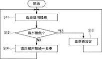
指が送信アンテナ部2に近接しているか否か(指がタッチパネルに接触しているか否か)を正確に判定することを利用して、座標入力装置900は、以下で説明する動作を行うことができる。図33は、座標入力装置900の動作を示すフローチャートである。 The coordinate
ステップS11
座標入力装置900は、起動時には、図32に示すように、アンテナ線を受信アンテナとして用いる(近距離用接続)。Step S11
As shown in FIG. 32, the coordinate
ステップS12
検出部4は、指が送信アンテナ部2に近接しているか否か(指がタッチパネルに接触しているか否か)を判定する。Step S12
The
ステップS13
指が送信アンテナ部2に近接している(指がタッチパネルに接触している)場合には、検出部4は、接続関係を維持する。そして、測定した信号の値を、指とタッチパネルとの間の距離が0である場合の基準値として設定する。その後、ステップS11へ戻る。Step S13
When the finger is close to the transmission antenna unit 2 (the finger is in contact with the touch panel), the
ステップS14
指が送信アンテナ部2に近接していない(指がタッチパネルに接触していない)場合には、検出部4は、MUX90の接続を切り替える(遠距離用接続へ変更)。これにより、受信アンテナ3と検出部4とが接続され、指が送信アンテナ部2に近接していない(指がタッチパネルに接触していない)ときでも、検出部4は指の位置を検出するこができる。なお、指とタッチパネルとの間の距離が0である場合の基準値が設定されているので、精度よく指とタッチパネルとの間の距離を測定することが可能である。その後は、ステップS11へ戻る。Step S14
When the finger is not close to the transmission antenna unit 2 (the finger is not in contact with the touch panel), the
よって、本構成によれば、近距離用接続時に基準値を校正することができるので、指が送信アンテナ部(タッチパネル)から離れている場合でも、指と送信アンテナ部(タッチパネル)との間の距離を精度よく検出することができる。 Therefore, according to this configuration, since the reference value can be calibrated at the time of short-distance connection, even when the finger is away from the transmission antenna unit (touch panel), the finger is not connected between the transmission antenna unit (touch panel). The distance can be detected with high accuracy.
実施の形態10
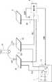
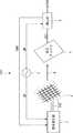
次に、実施の形態10にかかる座標入力装置1000について説明する。図34は、実施の形態10にかかる座標入力装置1000の構成を模式的に示す図である。座標入力装置1000は、実施の形態1にかかる座標入力装置100にMUX14と電流計AMMとを追加した構成を有する。MUX14は、送信アンテナ部2の10本のアンテナ線と電流計AMMとを接続するように構成される。なお、検出部4は、制御信号CON5により、検出部4にアンテナ線のいずれを接続するかを制御することができる。
Next, a coordinate
図35は、静電容量式で指10の位置を検出する場合の座標入力装置1000の接続を示す図である。図35では、簡略化のため、送信アンテナ部2のアンテナ線の内、アンテナ線X1及びX2のみを図示している。この例では、MUX13は、信号発振部11とアンテナ線X1とを接続する。MUX14は、アンテナ線X2と電流計AMMとを接続する。これにより、図8で示す場合と同様に、静電容量式での位置検出が可能となる。 FIG. 35 is a diagram illustrating the connection of the coordinate
図36は、指10と送信アンテナ部2とが離れている場合の指の位置を検出する場合の座標入力装置1000の接続を示す図である。図36では、簡略化のため、送信アンテナ部2のアンテナ線の内、アンテナ線X1及びX2のみを図示している。この例では、MUX13は、信号発振部11とアンテナ線X1とを接続する。MUX14は、電流計AMMをいずれのアンテナ線とも接続しない。これにより、図9で示す場合と同様に、指と送信アンテナ部2とが離れている場合でも、指の位置検出が可能となる。 FIG. 36 is a diagram illustrating the connection of the coordinate
静電容量式と指と送信アンテナ部2とが離れている場合の位置検出方式とを併用することで、座標入力装置1000は、以下で説明する動作を行うことができる。図37は、座標入力装置1000の動作を示すフローチャートである。 By using the capacitance type and the position detection method when the finger and the
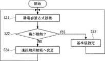
ステップS21
座標入力装置1000は、起動時には、図35に示すように、静電容量式での位置検出を行う接続を行う。すなわち、MUX13によって信号発生部1とアンテナ線(図35のアンテナ線X1)とを接続し、MUX14によってアンテナ線(図35のアンテナ線X2)と電流計AMMとを接続する。Step S21
When the coordinate
ステップS22
検出部4は、指がタッチパネルに接触しているか否かを判定する。Step S22
The
ステップS23
指がタッチパネルに接触している場合には、検出部4は、そのまま指の位置を検出する。そして、測定した信号の値を、指とタッチパネルとの間の距離が0である場合の基準値として設定する。その後、ステップS21へ戻る。Step S23
When the finger is in contact with the touch panel, the
ステップS24
指がタッチパネルに接触していない場合には、検出部4は、MUX14の接続を切り替える(遠距離用接続へ変更)。これにより、指がタッチパネルに接触していないときでも、検出部4は指の位置を検出することができる。なお、指とタッチパネルとの間の距離が0である場合の基準値が設定されているので、精度よく指とタッチパネルとの間の距離を測定することが可能である。その後は、ステップS21へ戻る。Step S24
When the finger is not in contact with the touch panel, the
よって、本構成によれば、静電容量式にて測定した値を用いて基準値を校正することができるので、指が送信アンテナ部(タッチパネル)から離れている場合でも、指と送信アンテナ部(タッチパネル)との間の距離を精度よく検出することができる。かつ、指の背食/非接触に応じて測定方式を切り替えることで、精度よく指の位置を検出することができる。 Therefore, according to this configuration, since the reference value can be calibrated using the value measured by the capacitance type, even when the finger is away from the transmission antenna unit (touch panel), the finger and the transmission antenna unit The distance to the (touch panel) can be accurately detected. In addition, the position of the finger can be detected with high accuracy by switching the measurement method in accordance with finger back-eating / non-contact.
実施の形態11
次に、実施の形態11にかかる座標入力装置1100について説明する。座標入力装置1100は、実施の形態1にかかる座標入力装置100の変形例である。図38は、実施の形態11にかかる座標入力装置1100の構成を模式的に示す図である。座標入力装置1100は、座標入力装置100に搬送波生成部6を追加し、かつ、座標入力装置100の信号発生部1及び検出部4を、それぞれ信号発生部7及び検出部8に置換した構成を有する。座標入力装置1100のその他の構成は、座標入力装置100と同様である。
Next, a coordinate
図39は、信号発生部7の構成を模式的に示す図である。信号発生部7は、信号発生部1にミキサM1を追加した構成を有する。ミキサM1は、信号発振部11と増幅器12との間に挿入される。ミキサM1は、信号発振部11からの交流信号SIGと搬送波生成部6からの搬送波CWとを混合し、増幅器12へ出力する。信号発生部7のその他の構成は、信号発生部1と同様であるので、説明を省略する。 FIG. 39 is a diagram schematically showing the configuration of the
図40は、検出部8の構成を模式的に示す図である。検出部8は、検出部4にミキサM2を追加した構成を有する。ミキサM2は、増幅器41とフィルタ42との間に挿入される。ミキサM2は、受信信号を搬送波CWと混合し、信号発振部11の交流信号SIGの周波数成分の受信信号に変換する。検出部8のその他の構成は、検出部4と同様であるので、説明を省略する。 FIG. 40 is a diagram schematically illustrating the configuration of the
本構成によれば、交流信号を直接送信する場合に比べて、フィルタ42に急峻な特性のものを使用することなく、周波数選択性を高めることができる。その結果、ノイズ耐性を高めることができる点で有利である。 According to this configuration, it is possible to improve frequency selectivity without using a filter having a steep characteristic as compared with the case of directly transmitting an AC signal. As a result, it is advantageous in that noise resistance can be increased.
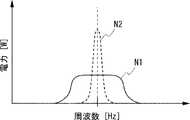
更に、搬送波生成部6は、出力する搬送波CWの周波数を一定の範囲内で周期的に変化させることができる。また、信号発生部7から出力される交流信号の周波数も一定の範囲内で周期的に変化させてもよい。この周波数変化は、1つのアンテナ線を選択している期間内で1周期の周波数変化をおこなうか、もしくは10本のアンテナ線を選択する毎に1回の周波数変化を行うことができる。 Furthermore, the carrier wave generation unit 6 can periodically change the frequency of the output carrier wave CW within a certain range. Further, the frequency of the AC signal output from the
図41は、搬送波及び交流信号の周波数を変化させたときのノイズの周波数スペクトルを示す図である。このように周波数を変化させると、送信アンテナ部2から放射されるノイズの周波数スペクトラムを、一定の周波数範囲で広がったものとすることができる(図41の実線N1)。よって、特定周波数へのノイズの集中(図41の破線N2)を防止することができる。その結果、放射ノイズによる他の機器への影響を低減することができる。 FIG. 41 is a diagram illustrating a frequency spectrum of noise when the frequencies of the carrier wave and the AC signal are changed. When the frequency is changed in this way, the frequency spectrum of noise radiated from the transmitting
実施の形態12
次に、実施の形態12にかかる座標入力装置について説明する。実施の形態12にかかる座標入力装置は、実施の形態1にかかる座標入力装置100と同様の構成を有する。本実施の形態では、交流信号を送信するアンテナ線を1本に固定した場合の応用例について説明する。
Next, a coordinate input device according to
上述の実施の形態では、交流信号を送信するアンテナ線を時系列で切り替えていた。これに対し、本実施の形態では、1本のアンテナ線から継続的に交流信号を送信する。図42は、実施の形態12にかかる座標入力装置での位置検出を模式的に示す図である。図42では、簡略化のため、送信アンテナ部2のアンテナ線の内、アンテナ線X1及びX2のみを図示しているまた、図42では、継続的に使用するアンテナ線を、アンテナ線X1としている。 In the above-described embodiment, the antenna line for transmitting the AC signal is switched in time series. In contrast, in the present embodiment, an AC signal is continuously transmitted from one antenna line. FIG. 42 is a diagram schematically illustrating position detection by the coordinate input device according to the twelfth embodiment. 42 shows only the antenna lines X1 and X2 among the antenna lines of the
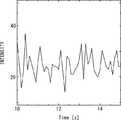
本実施の形態では、例えばアンテナ線X1から継続的に交流信号を送信し、受信信号の強度の時間変化を観測する。この際、信号が伝達される経路(送信アンテナ部2と受信アンテナ3との間)に人体10cが存在すると、送信した信号が規則的な正弦波であっても、人体10cは脈拍などの影響により信号の伝達特性が時間的に変化する。そのため、受信信号は、前述の時間的な変化が重畳され、時間的に振幅が変化する波形となる。そこで、フィルタ処理により、受信信号から数Hz程度の低周波成分を取り出すことで、人体10cの脈拍を検出することができる。 In the present embodiment, for example, an AC signal is continuously transmitted from the antenna line X1, and a temporal change in the strength of the received signal is observed. At this time, if the
図43は、受信信号から取り出された低周波数成分の波形の例を示す図である。本実施の形態によれば、このように、人体の脈拍を示す波形成分を取得することが可能となる。その結果、例えば携帯端末を使用するユーザの健康管理等に、脈拍データを活用することができる。さらに、脈拍の有無を検出することで、本実施の形態にかかる座標入力装置に接近している導体が生物であるかどうかを判別することができる。 FIG. 43 is a diagram illustrating an example of a waveform of a low-frequency component extracted from the received signal. According to the present embodiment, it is possible to acquire the waveform component indicating the pulse of the human body in this way. As a result, for example, the pulse data can be used for health management of a user who uses the mobile terminal. Furthermore, by detecting the presence or absence of a pulse, it is possible to determine whether or not the conductor approaching the coordinate input device according to the present embodiment is a living thing.
その他の実施の形態
なお、本発明は上記実施の形態に限られたものではなく、趣旨を逸脱しない範囲で適宜変更することが可能である。例えば、上述の実施の形態では、タッチパネルに送信アンテナ部が組み込まれ、その他の部分に受信アンテナを配置した例について説明したが、これは例示に過ぎない。例えば、タッチパネルに1又は複数の受信アンテナを組み込み、その他の部分に送信アンテナ部のアンテナ線と同等の構成を配置しても、上述の実施の形態にかかる座標入力装置と同様の座標入力装置を実現することができる。Other Embodiments The present invention is not limited to the above-described embodiments, and can be appropriately changed without departing from the spirit of the present invention. For example, in the above-described embodiment, the example in which the transmission antenna unit is incorporated in the touch panel and the reception antenna is arranged in the other part has been described, but this is only an example. For example, a coordinate input device similar to the coordinate input device according to the above-described embodiment is provided even if one or a plurality of reception antennas are incorporated in the touch panel and a configuration equivalent to the antenna line of the transmission antenna unit is disposed in other portions. Can be realized.
上述の座標入力装置500に、複数の受信アンテナを設けることが可能であることは言うまでもない。例えば、座標入力装置500に、座標入力装置600又は700におけるように、複数のアンテナとマルチプレクサを設けてもよい。また、座標入力装置500に、設定値の設定(実施の形態9の座標入力装置900)、検出方式の切り替え(実施の形態10の座標入力装置1000)及び搬送波の利用(実施の形態11の座標入力装置1100)の一部又は全部を組み合わせることも可能である。 Needless to say, the coordinate
上述の座標入力装置900、1000及び1100に、複数の受信アンテナを設けることが可能であることは言うまでもない。例えば、座標入力装置900、1000及び1100に、座標入力装置600又は700におけるように、複数のアンテナとマルチプレクサを設けてもよい。設定値の設定(実施の形態9の座標入力装置900)、検出方式の切り替え(実施の形態10の座標入力装置1000)及び搬送波の利用(実施の形態11の座標入力装置1100)は、適宜組み合わせて使用することが可能である。 Needless to say, the coordinate
座標入力装置500、600、700、900、1000、1100、及び、上述の組み合わせによる他の座標入力装置に、上述で説明した各実施の形態で説明した技術を適用できることはいうまでもない。すなわち、座標入力装置500、600、700、900、1000、1100、及び、上述の組み合わせによる他の座標入力装置に、多項式の使用による検出精度の向上(実施の形態2)又は予想分布の使用による検出精度の向上(実施の形態3)を適用することができる。また、座標入力装置500、600、700、900、1000、1100、及び、上述の組み合わせによる他の座標入力装置に、アンテナ線及び受信アンテナの形状(実施の形態4)による検出精度の向上、誤検出の防止(実施の形態8)及び人体の脈拍測定(実施の形態12)の技術の一部1又は全部を適用できる。 Needless to say, the technology described in each of the embodiments described above can be applied to the coordinate
上述の実施の形態では、座標入力装置及び携帯端末の構成を説明するため、X方向とY方向とが直交するものとして説明した。しかしX方向とY方向とは、必ずしも直交していなければならないものではなく、直角以外の所定の角度で交わるものであってもよい。 In the above-described embodiment, in order to describe the configuration of the coordinate input device and the mobile terminal, the X direction and the Y direction are assumed to be orthogonal to each other. However, the X direction and the Y direction do not necessarily have to be orthogonal to each other, and may intersect at a predetermined angle other than a right angle.
以上、本発明者によってなされた発明を実施の形態に基づき具体的に説明したが、本発明は既に述べた実施の形態に限定されるものではなく、その要旨を逸脱しない範囲において種々の変更が可能であることはいうまでもない。 As mentioned above, the invention made by the present inventor has been specifically described based on the embodiments. However, the present invention is not limited to the embodiments already described, and various modifications can be made without departing from the scope of the invention. It goes without saying that it is possible.
上記の実施の形態の一部又は全部は、以下の付記のようにも記載され得るが、以下には限られない。 A part or all of the above embodiment can be described as in the following supplementary notes, but is not limited thereto.
(付記1)交流信号を出力する信号発生部と、前記交流信号に応じた信号を送受信する複数の第1のアンテナを有する第1の送受信部と、第1の送受信部との間で前記信号を送受信する1つまたは複数の第2のアンテナを有する第2の送受信部と、前記第1の送受信部が前記信号を送受信した際に前記複数の第1のアンテナの位置に対応した前記信号の強度分布を取得し、前記強度分布のピークの位置に応じて検出位置を検出する検出部と、を備える、座標入力装置。 (Supplementary note 1) The signal between the signal generation unit that outputs an AC signal, the first transmission / reception unit having a plurality of first antennas that transmit and receive a signal corresponding to the AC signal, and the first transmission / reception unit A second transmitter / receiver having one or more second antennas for transmitting / receiving the signal, and the signal corresponding to the position of the plurality of first antennas when the first transmitter / receiver transmits / receives the signal. A coordinate input device comprising: a detection unit that acquires an intensity distribution and detects a detection position according to a peak position of the intensity distribution.
(付記2)前記信号発生部は、前記第1の送受信部の前記複数の第1のアンテナのいずれかに前記交流信号を出力し、複数の第1のアンテナのうち、前記交流信号が供給されたものから前記信号が送信され、前記第2の送受信部は、第2のアンテナで前記信号を受信する、付記1に記載の座標入力装置。 (Additional remark 2) The said signal generation part outputs the said alternating current signal to either of the said some 1st antennas of the said 1st transmission / reception part, and the said alternating current signal is supplied among several 1st antennas. The coordinate input device according to
(付記3)前記信号発生部は、前記第2の送受信部に前記交流信号を出力し、前記第2の送受信部から第2のアンテナで前記信号が送信され、複数の第1のアンテナのうちのいずれかで前記信号を受信する、付記1に記載の座標入力装置。 (Additional remark 3) The said signal generation part outputs the said alternating current signal to a said 2nd transmission / reception part, and the said signal is transmitted with a 2nd antenna from the said 2nd transmission / reception part, Among several 1st antennas The coordinate input device according to
(付記4)前記検出部は、前記信号を、導電体を介して受信し、前記検出位置は、前記導電体の位置を示す、
付記1に記載の座標入力装置。(Appendix 4) The detection unit receives the signal via a conductor, and the detection position indicates a position of the conductor.
The coordinate input device according to
(付記5)前記導電体は、人体である、付記4に記載の座標入力装置。 (Supplementary note 5) The coordinate input device according to
(付記6)前記検出部は、1または複数の前記ピークに応じて、1又は複数の前記検出位置を検出する、付記1に記載の座標入力装置。 (Supplementary note 6) The coordinate input device according to
(付記7)前記複数の第1のアンテナは、所定の方向に整列して配置され、前記検出部は、前記複数の第1のアンテナについて検出した前記信号の強度を前記所定の方向の位置を変数とする多項式で近似し、前記多項式の値が最大となる前記所定の方向の位置を前記検出位置として検出する、付記1に記載の座標入力装置。 (Supplementary note 7) The plurality of first antennas are arranged in a predetermined direction, and the detection unit determines the intensity of the signal detected for the plurality of first antennas in the position in the predetermined direction. The coordinate input device according to
(付記8)前記複数の第1のアンテナは、所定の方向に整列して配置され、前記検出部は、前記複数の第1のアンテナについて検出した前記信号の強度に前記所定の方向の位置を変数とする予測分布を当てはめ、前記予測分布との相関が最大となる前記所定の方向の位置を前記検出位置として検出する、付記1に記載の座標入力装置。 (Supplementary note 8) The plurality of first antennas are arranged in a predetermined direction, and the detection unit sets the position of the predetermined direction to the intensity of the signal detected for the plurality of first antennas. The coordinate input device according to
(付記9)前記検出部は、前記検出位置における前記信号の強度に基づいて、前記第1の送受信部の第1のアンテナと前記第2の送受信部の第2のアンテナとの間に挿入される導電体と前記第1の送受信部の第1のアンテナとの間の距離を検出する、付記2に記載の座標入力装置。 (Additional remark 9) The said detection part is inserted between the 1st antenna of the said 1st transmission / reception part and the 2nd antenna of the said 2nd transmission / reception part based on the intensity | strength of the said signal in the said detection position. The coordinate input device according to
(付記10)前記信号発生部は、周波数の異なる複数種類の交流信号を出力し、前記検出部は、前記信号発生部が第1の周波数の交流信号を出力している場合に前記第1のアンテナを含む平面に平行な位置を検出し、前記信号発生部が前記第1の周波数よりも高い周波数である第2の周波数の交流信号を出力している場合に前記第1のアンテナを含む平面に垂直な位置を検出する、付記9に記載の座標入力装置。 (Additional remark 10) The said signal generation part outputs several types of alternating current signal from which frequency differs, The said detection part is said 1st when the said signal generation part is outputting the alternating current signal of 1st frequency. A plane including the first antenna when a position parallel to the plane including the antenna is detected and the signal generator outputs an AC signal having a second frequency higher than the first frequency. The coordinate input device according to appendix 9, wherein a position perpendicular to is detected.
(付記11)前記検出部は、
前記複数の第1のアンテナのうち、1つのアンテナ線からの前記信号を、前記複数の第1のアンテナのうちの他のアンテナを介して前記第2の送受信部で受信し、
受信した前記信号の強度が所定値よりも大きい場合に、前記導電体と前記第1の送受信部との間の距離が0である場合の基準強度として設定する、
付記10に記載の座標入力装置。
(Supplementary Note 11) The detection unit includes:
The signal from one antenna line among the plurality of first antennas is received by the second transmitting / receiving unit via another antenna of the plurality of first antennas,
When the intensity of the received signal is greater than a predetermined value, set as a reference intensity when the distance between the conductor and the first transmission / reception unit is 0,
The coordinate input device according to
(付記12)前記第1の送受信部は、静電容量式のタッチパネルに組み込まれ、前記複数の第1のアンテナの全てもしくは複数個は、前記静電容量式のタッチパネルの電極として機能する、付記9に記載の座標入力装置。 (Supplementary Note 12) The first transmission / reception unit is incorporated in a capacitive touch panel, and all or a plurality of the plurality of first antennas function as electrodes of the capacitive touch panel. The coordinate input device according to 9.
(付記13)前記静電容量式のタッチパネルの位置検出と並列又は独立に前記信号発生部は、前記第1の送受信部の前記複数の第1のアンテナのいずれかに前記交流信号を出力し、前記検出部は、前記複数の第1のアンテナのそれぞれについて検出した前記信号の強度を比較して前記検出位置を検出する、付記12に記載の座標入力装置。 (Supplementary note 13) In parallel or independently of position detection of the capacitive touch panel, the signal generation unit outputs the AC signal to any of the plurality of first antennas of the first transmission / reception unit, The coordinate input device according to
(付記14)前記信号発生部及び前記検出部に搬送波を出力する搬送波生成部を更に備え、前記信号発生部は、前記交流信号と前記搬送波を混合して出力し、前記第1の送受信部の前記複数の第1のアンテナは、混合された前記交流信号及び前記搬送波に応じた前記信号を送信し、前記検出部は、前記複数の第1のアンテナのそれぞれについて前記搬送波を除去した後の前記交流信号に対応する前記信号の強度を検出する、付記1に記載の座標入力装置。 (Supplementary Note 14) A carrier generation unit that outputs a carrier wave to the signal generation unit and the detection unit is further included. The signal generation unit mixes and outputs the AC signal and the carrier, and the first transmission / reception unit The plurality of first antennas transmit the mixed AC signal and the signal corresponding to the carrier wave, and the detection unit removes the carrier wave for each of the plurality of first antennas. The coordinate input device according to
(付記15)前記搬送波生成部は、周波数が時間的に変化する搬送波を出力する、付記14に記載の座標入力装置。 (Supplementary note 15) The coordinate input device according to
(付記16)前記第2の送受信部を複数備え、前記検出部は、前記複数の第1のアンテナのそれぞれについて、複数の前記第2の送受信部のいずれかの第2のアンテナで受信した前記信号の強度を検出し、検出した前記信号の強度が最大となる第1のアンテナの位置に応じて検出位置を検出する、付記1に記載の座標入力装置。 (Supplementary Note 16) A plurality of the second transmission / reception units are provided, and the detection unit receives each of the plurality of first antennas from a second antenna of the plurality of second transmission / reception units. The coordinate input device according to
(付記17)前記第2の送受信部を複数備え、前記検出部は、前記複数の第1のアンテナのそれぞれについて、複数の前記第2の送受信部のいずれかの第2のアンテナで受信した前記信号の強度を検出し、検出した前記信号の強度を比較して検出位置を検出したのち、前記複数の第1のアンテナのそれぞれについて、複数の前記第2の送受信部のうちの他の第2の送受信部の第2のアンテナのいずれかで受信した前記信号の強度を検出し、検出した前記信号の強度を比較して検出位置を検出する、付記1に記載の座標入力装置。 (Additional remark 17) The said 2nd transmission / reception part is provided with two or more, The said detection part received with the 2nd antenna in any one of a said some 2nd transmission / reception part about each of the said some 1st antenna After detecting the signal strength and comparing the detected signal strengths to detect the detection position, each of the plurality of first antennas is subjected to another second of the plurality of second transmission / reception units. The coordinate input device according to
(付記18)前記複数の第1のアンテナは、第1の方向に整列した複数の第1のアンテナ組と、前記第1の方向と異なる第2の方向に整列した複数の第2のアンテナ組と、を含み、前記検出部は、前記複数の第1のアンテナ組のそれぞれのアンテナについて、前記第2の送受信部で受信した前記信号の強度を検出し、検出した前記信号の強度を比較して第1の位置として検出し、前記複数の第2のアンテナ組のそれぞれについて、前記第2の送受信部で受信した前記信号の強度を検出し、検出した前記信号の強度を比較して第2の位置として検出し、前記第1の位置と前記第2の位置とで表される座標を、前記検出位置として検出する、付記1に記載の座標入力装置。 (Supplementary note 18) The plurality of first antennas includes a plurality of first antenna sets aligned in a first direction and a plurality of second antenna sets aligned in a second direction different from the first direction. And the detection unit detects the intensity of the signal received by the second transmission / reception unit for each antenna of the plurality of first antenna sets, and compares the detected signal strength. Detecting the first position, detecting the intensity of the signal received by the second transmitting / receiving unit for each of the plurality of second antenna sets, and comparing the detected intensity of the signal to the second position The coordinate input device according to
(付記19)前記検出部は、前記複数の第1のアンテナ組を用いて検出される第1の位置と前記複数の第2のアンテナ組を用いて検出される第2の位置が一致しない場合は前記第1と第2の検出位置を無効とする、付記18に記載の座標入力装置。 (Supplementary Note 19) When the detection unit does not match a first position detected using the plurality of first antenna sets and a second position detected using the plurality of second antenna sets. The coordinate input device according to appendix 18, wherein the first and second detection positions are invalidated.
(付記20)前記第2の送受信部を複数備え、前記検出部は、前記複数の第1のアンテナのそれぞれについて、複数の前記第2の送受信部のいずれかで受信した前記信号の強度を検出し、検出した前記信号の強度を比較して検出位置を検出する、付記18に記載の座標入力装置。 (Additional remark 20) It has two or more said 2nd transmission / reception parts, The said detection part detects the intensity | strength of the said signal received in either of several said 2nd transmission / reception parts about each of these 1st antennas The coordinate input device according to appendix 18, wherein the detected position is detected by comparing the detected intensities of the signals.
(付記21)前記検出部は、前記複数の第1のアンテナのいずれかについて前記第2の送受信部で受信した前記信号の強度から所定の周波数成分を抽出し、前記第1の送受信部の第1のアンテナと前記第2の送受信部の第2のアンテナとの間に挿入される導電体の状態変化を検出する、付記1に記載の座標入力装置。 (Additional remark 21) The said detection part extracts a predetermined | prescribed frequency component from the intensity | strength of the said signal received by the said 2nd transmission / reception part about either of these 1st antennas, and the 1st transmission / reception part of the said 1st transmission / reception part The coordinate input device according to
(付記22)前記導電体は人体であり、前記検出部は、前記所定の低周波成分の強度変化から、脈拍を検出する、付記20に記載の座標入力装置。 (Supplementary note 22) The coordinate input device according to
(付記23)付記22において、脈拍の有無により、前記導電体が生物であるかどうかを判別する付記22に記載の座標入力装置。 (Supplementary note 23) The coordinate input device according to
(付記24)前記交流信号の波長は、前記第1の送受信部及び前記第2の送受信部の大きさの10倍以上である、付記1に記載の座標入力装置。 (Supplementary note 24) The coordinate input device according to
(付記25)前記複数のアンテナのそれぞれは、前記第1の送受信部の主面に沿って配置される直線状のアンテナであり、前記第2の送受信部は、平板状のアンテナである、付記1に記載の座標入力装置。 (Supplementary Note 25) Each of the plurality of antennas is a linear antenna disposed along a main surface of the first transmission / reception unit, and the second transmission / reception unit is a flat antenna. The coordinate input device according to 1.
(付記26)導電体の位置を検出する座標入力装置であって、交流信号を出力する信号発生部と、前記交流信号に応じた信号を送受信する複数の第1のアンテナを有する第1の送受信部と、第1の送受信部との間で前記信号を送受信する1つまたは複数の第2のアンテナを有する第2の送受信部と、前記第1の送受信部が前記信号を送受信した際に前記複数の第1のアンテナの位置に対応した前記信号の強度分布を取得し、前記強度分布のピークの位置に応じて、前記第1の送受信部の複数の第1のアンテナと前記第2の送受信部の1つまたは複数の第2のアンテナとの間に挿入された前記導電体の位置を検出する検出部と、を備える、座標入力装置。 (Supplementary Note 26) A coordinate input device for detecting the position of a conductor, a first transmission / reception having a signal generating unit for outputting an AC signal and a plurality of first antennas for transmitting / receiving a signal corresponding to the AC signal. And a second transmitter / receiver having one or more second antennas for transmitting / receiving the signal between the first transmitter / receiver and the first transmitter / receiver when the first transmitter / receiver transmits / receives the signal. The signal intensity distribution corresponding to the positions of the plurality of first antennas is acquired, and the plurality of first antennas and the second transmission / reception of the first transmission / reception unit according to the position of the peak of the intensity distribution A detection unit that detects a position of the conductor inserted between one or a plurality of second antennas of the unit.
(付記27)付記26に記載の前記座標入力装置が組み込まれ、前記第1の送受信部の複数の第1のアンテナはが第1の面のみに配置され、複数の前記第2の送受信部の第2のアンテナそれぞれは、前記第1の面又は前記第1の面とは異なる面に配置される
携帯端末。(Supplementary note 27) The coordinate input device according to Supplementary note 26 is incorporated, and the plurality of first antennas of the first transmission / reception unit are arranged only on the first surface, and the plurality of second transmission / reception units Each of the second antennas is a mobile terminal arranged on the first surface or a surface different from the first surface.
(付記28)複数の第2の送受信部は、第3の送受信部及び第4の送受信部を含み、前記第3の送受信部は、前記複数の第1のアンテナのそれぞれから等距離となるように、前記第1の送受信部から前記第1の方向に離隔して配置され、前記第4の送受信部は、前記複数の第2のアンテナのそれぞれから等距離となるように、前記第1の送受信部から前記第2の方向に離隔して配置され、前記検出部は、前記第3の送受信部により、前記複数の第1のアンテナのそれぞれについて前記信号の強度を検出し、前記第4の送受信部により、前記複数の第2のアンテナのそれぞれについて前記信号の強度を検出する、付記25に記載の携帯端末。 (Supplementary Note 28) The plurality of second transmission / reception units include a third transmission / reception unit and a fourth transmission / reception unit, and the third transmission / reception unit is equidistant from each of the plurality of first antennas. The first transmitting / receiving unit is spaced apart from the first transmitting / receiving unit in the first direction, and the fourth transmitting / receiving unit is equidistant from each of the plurality of second antennas. The detection unit is arranged to be separated from the transmission / reception unit in the second direction, and the detection unit detects the intensity of the signal for each of the plurality of first antennas by the third transmission / reception unit, and the fourth transmission unit The mobile terminal according to appendix 25, wherein the signal intensity is detected for each of the plurality of second antennas by a transmission / reception unit.
(付記29)付記1に記載の前記座標入力装置が組み込まれる、携帯端末。 (Supplementary note 29) A mobile terminal in which the coordinate input device according to
1、5、7 信号発生部
2 送信アンテナ部
3 受信アンテナ
4 検出部
6 搬送波生成部
8 検出部
10 指
10a 左手
10b 右手
10c 人体
11、51 信号発振部
12 増幅器
13、14、60、70、90 MUX
41 増幅器
42 フィルタ
43 検波部
44 A/Dコンバータ
45 位置検出部
61〜63 受信アンテナ
71〜77 受信アンテナ
100、500、600、700、900、1000、1100 座標入力装置
101、601、701、707 携帯端末
102、602、702 筐体
103、603、703 タッチパネル
604、704 表面
605、705、708 側面
606 裏面
800 タッチパネル
801 透明抵抗シート
802 突起
803 透明電極シート803
804〜807 辺
808〜811 ダイオード群
812 電源
813 スイッチ
814 ペン
815、816 点
817 検出回路
900 タッチパネルシステム
910 タッチパネル
920 タッチパネルコントローラ
911 センサ
921 座標検出手段
922 CPU
923 操作感度変更手段
CON1〜CON5 制御信号
CW 搬送波
DL ドライブライン
E11、E12 電極
AMM 電流計
M1、M2 ミキサ
RS1〜RS3、RSd 受信信号
SIG、SIG1、SIG2 交流信号
S1 発振器
SL センスライン
Ts 端子
TX1〜TX5 端子
TY1〜TY5 端子
X1〜X5、Y1〜Y5 アンテナ線DESCRIPTION OF
41
804 to 807
923 Operation sensitivity changing means CON1-CON5 Control signal CW Carrier DL Drive line E11, E12 Electrode AMM Ammeter M1, M2 Mixer RS1-RS3, RSd Received signal SIG, SIG1, SIG2 AC signal S1 Oscillator SL Sense line Ts terminal TX1- TX5 terminal TY1 to TY5 terminal X1 toX5,Y1 toY5 Antenna wire
Claims (20)
Translated fromJapanese前記交流信号に応じた信号を送受信する複数の第1のアンテナを有する第1の送受信部と、
第1の送受信部との間で前記信号を送受信する1つまたは複数の第2のアンテナを有する第2の送受信部と、
前記第1の送受信部が前記信号を送受信した際に前記複数の第1のアンテナの位置に対応した前記信号の強度分布を取得し、前記強度分布のピークの位置に応じて検出位置を検出する検出部と、を備える、
座標入力装置。A signal generator for outputting an AC signal;
A first transmission / reception unit having a plurality of first antennas for transmitting and receiving a signal corresponding to the AC signal;
A second transceiver having one or more second antennas for transmitting and receiving the signal to and from the first transceiver;
When the first transmitter / receiver transmits / receives the signal, the signal intensity distribution corresponding to the position of the plurality of first antennas is acquired, and a detection position is detected according to a peak position of the intensity distribution. A detection unit,
Coordinate input device.
複数の第1のアンテナのうち、前記交流信号が供給されたものから前記信号が送信され、
前記第2の送受信部は、2のアンテナで前記信号を受信する、
請求項1に記載の座標入力装置。The signal generator outputs the AC signal to any one of the plurality of first antennas of the first transceiver.
The signal is transmitted from the plurality of first antennas supplied with the AC signal,
The second transmitting / receiving unit receives the signal with two antennas,
The coordinate input device according to claim 1.
前記第2の送受信部から第2のアンテナで前記信号が送信され、
複数の第1のアンテナのうちのいずれかで前記信号を受信する、
請求項1に記載の座標入力装置。The signal generation unit outputs the AC signal to the second transmission / reception unit,
The signal is transmitted from the second transceiver to the second antenna,
Receiving the signal at any of a plurality of first antennas;
The coordinate input device according to claim 1.
前記検出位置は、前記導電体の位置を示す、
請求項1に記載の座標入力装置。The detection unit receives the signal via a conductor,
The detection position indicates the position of the conductor.
The coordinate input device according to claim 1.
請求項4に記載の座標入力装置。The conductor is a human body.
The coordinate input device according to claim 4.
請求項1に記載の座標入力装置。The detection unit detects one or a plurality of the detection positions according to one or a plurality of the peaks.
The coordinate input device according to claim 1.
前記検出部は、前記複数の第1のアンテナについて検出した前記信号の強度を前記所定の方向の位置を変数とする多項式で近似し、前記多項式の値が最大となる前記所定の方向の位置を前記検出位置として検出する、
請求項1に記載の座標入力装置。The plurality of first antennas are arranged in alignment in a predetermined direction,
The detection unit approximates the intensity of the signal detected for the plurality of first antennas by a polynomial having a position in the predetermined direction as a variable, and determines a position in the predetermined direction where the value of the polynomial is maximum. Detect as the detection position,
The coordinate input device according to claim 1.
前記検出部は、前記複数の第1のアンテナについて検出した前記信号の強度に前記所定の方向の位置を変数とする予測分布を当てはめ、前記予測分布との相関が最大となる前記所定の方向の位置を前記検出位置として検出する、
請求項1に記載の座標入力装置。The plurality of first antennas are arranged in alignment in a predetermined direction,
The detection unit applies a prediction distribution having the position in the predetermined direction as a variable to the intensity of the signal detected for the plurality of first antennas, and has a maximum correlation with the prediction distribution in the predetermined direction. Detecting a position as the detection position;
The coordinate input device according to claim 1.
請求項2に記載の座標入力装置。The detection unit includes a conductor inserted between the first antenna of the first transmission / reception unit and the second antenna of the second transmission / reception unit based on the intensity of the signal at the detection position. Detecting a distance from the first antenna of the first transceiver unit;
The coordinate input device according to claim 2.
前記検出部は、前記信号発生部が第1の周波数の交流信号を出力している場合に前記第1のアンテナを含む平面に平行な位置を検出し、前記信号発生部が前記第1の周波数よりも高い周波数である第2の周波数の交流信号を出力している場合に前記第1のアンテナを含む平面に垂直な位置を検出する、
請求項9に記載の座標入力装置。The signal generator outputs a plurality of types of AC signals having different frequencies,
The detection unit detects a position parallel to a plane including the first antenna when the signal generation unit outputs an AC signal having a first frequency, and the signal generation unit detects the first frequency. Detecting a position perpendicular to a plane including the first antenna when an AC signal of a second frequency that is a higher frequency is being output;
The coordinate input device according to claim 9.
前記複数の第1のアンテナのうち、1つのアンテナ線からの前記信号を、前記複数の第1のアンテナのうちの他のアンテナを介して前記第2の送受信部で受信し、
受信した前記信号の強度が所定値よりも大きい場合に、前記導電体と前記第1の送受信部との間の距離が0である場合の基準強度として設定する、
請求項10に記載の座標入力装置。The detector is
The signal from one antenna line among the plurality of first antennas is received by the second transmitting / receiving unit via another antenna of the plurality of first antennas,
When the intensity of the received signal is greater than a predetermined value, set as a reference intensity when the distance between the conductor and the first transmission / reception unit is 0,
The coordinate input device according to claim 10.
前記複数の第1のアンテナの全てもしくは複数個は、前記静電容量式のタッチパネルの電極として機能する、
請求項9に記載の座標入力装置。The first transmission / reception unit is incorporated in a capacitive touch panel,
All or a plurality of the plurality of first antennas function as electrodes of the capacitive touch panel.
The coordinate input device according to claim 9.
前記検出部は、前記複数の第1のアンテナのそれぞれについて検出した前記信号の強度を比較して前記検出位置を検出する、
請求項12に記載の座標入力装置。In parallel or independently of position detection of the capacitive touch panel, the signal generator outputs the AC signal to any of the plurality of first antennas of the first transmitter / receiver,
The detection unit detects the detection position by comparing the intensity of the signal detected for each of the plurality of first antennas;
The coordinate input device according to claim 12.
前記信号発生部は、前記交流信号と前記搬送波を混合して出力し、
前記第1の送受信部の前記複数の第1のアンテナは、混合された前記交流信号及び前記搬送波に応じた前記信号を送信し、
前記検出部は、前記複数の第1のアンテナのそれぞれについて前記搬送波を除去した後の前記交流信号に対応する前記信号の強度を検出する、
請求項1に記載の座標入力装置。A carrier generation unit that outputs a carrier wave to the signal generation unit and the detection unit;
The signal generator mixes and outputs the AC signal and the carrier wave,
The plurality of first antennas of the first transmission / reception unit transmit the mixed AC signal and the signal corresponding to the carrier wave,
The detection unit detects the intensity of the signal corresponding to the AC signal after removing the carrier wave for each of the plurality of first antennas.
The coordinate input device according to claim 1.
請求項14に記載の座標入力装置。The carrier wave generation unit outputs a carrier wave whose frequency changes with time.
The coordinate input device according to claim 14.
前記検出部は、
前記複数の第1のアンテナのそれぞれについて、複数の前記第2の送受信部のいずれかの第2のアンテナで受信した前記信号の強度を検出し、検出した前記信号の強度を比較して検出位置を検出する、
請求項1に記載の座標入力装置。A plurality of the second transmission / reception units;
The detector is
For each of the plurality of first antennas, a detection position is detected by detecting the intensity of the signal received by the second antenna of any of the plurality of second transmission / reception units, and comparing the detected intensity of the signal. Detect
The coordinate input device according to claim 1.
前記検出部は、
前記複数の第1のアンテナのそれぞれについて、複数の前記第2の送受信部のいずれかの第2のアンテナで受信した前記信号の強度を検出し、検出した前記信号の強度を比較して検出位置を検出したのち、
前記複数の第1のアンテナのそれぞれについて、複数の前記第2の送受信部のうちの他の第2の送受信部の第2のアンテナのいずれかで受信した前記信号の強度を検出し、検出した前記信号の強度を比較して検出位置を検出する、
請求項1に記載の座標入力装置。A plurality of the second transmission / reception units;
The detector is
For each of the plurality of first antennas, a detection position is detected by detecting the intensity of the signal received by the second antenna of any of the plurality of second transmission / reception units, and comparing the detected intensity of the signal. After detecting
For each of the plurality of first antennas, the intensity of the signal received by any one of the second antennas of the other second transmission / reception units among the plurality of second transmission / reception units is detected and detected. Detecting the detection position by comparing the intensity of the signal;
The coordinate input device according to claim 1.
第1の方向に整列した複数の第1のアンテナ組と、
前記第1の方向と異なる第2の方向に整列した複数の第2のアンテナ組と、を含み、
前記検出部は、
前記複数の第1のアンテナ組のそれぞれのアンテナについて、前記第2の送受信部で受信した前記信号の強度を検出し、検出した前記信号の強度を比較して第1の位置として検出し、
前記複数の第2のアンテナ組のそれぞれについて、前記第2の送受信部で受信した前記信号の強度を検出し、検出した前記信号の強度を比較して第2の位置として検出し、
前記第1の位置と前記第2の位置とで表される座標を、前記検出位置として検出する、
請求項1に記載の座標入力装置。The plurality of first antennas are:
A plurality of first antenna sets aligned in a first direction;
A plurality of second antenna sets aligned in a second direction different from the first direction;
The detector is
For each antenna of the plurality of first antenna sets, detect the strength of the signal received by the second transmitting / receiving unit, compare the detected signal strength and detect as a first position,
For each of the plurality of second antenna sets, the intensity of the signal received by the second transceiver unit is detected, the detected intensity of the signal is compared and detected as a second position,
Detecting coordinates represented by the first position and the second position as the detection position;
The coordinate input device according to claim 1.
交流信号を出力する信号発生部と、
前記交流信号に応じた信号を送受信する複数の第1のアンテナを有する第1の送受信部と、
第1の送受信部との間で前記信号を送受信する1つまたは複数の第2のアンテナを有する第2の送受信部と、
前記第1の送受信部が前記信号を送受信した際に前記複数の第1のアンテナの位置に対応した前記信号の強度分布を取得し、前記強度分布のピークの位置に応じて、前記第1の送受信部の前記複数の第1のアンテナと前記第2の送受信部の前記1つまたは複数の第2のアンテナとの間に挿入された前記導電体の位置を検出する検出部と、を備える、
座標入力装置。A coordinate input device for detecting the position of a conductor,
A signal generator for outputting an AC signal;
A first transmission / reception unit having a plurality of first antennas for transmitting and receiving a signal corresponding to the AC signal;
A second transceiver having one or more second antennas for transmitting and receiving the signal to and from the first transceiver;
When the first transmission / reception unit transmits / receives the signal, the signal acquisition unit obtains an intensity distribution of the signal corresponding to a position of the plurality of first antennas, and determines the first distribution according to a peak position of the intensity distribution. A detection unit that detects a position of the conductor inserted between the plurality of first antennas of the transmission / reception unit and the one or more second antennas of the second transmission / reception unit;
Coordinate input device.
前記第1の送受信部の複数の第1のアンテナは第1の面のみに配置され、
複数の前記第2の送受信部の第2のアンテナそれぞれは、前記第1の面又は前記第1の面とは異なる面に配置される、
携帯端末。The coordinate input device according to claim 18 is incorporated,
The plurality of first antennas of the first transmission / reception unit are disposed only on the first surface,
Each of the second antennas of the plurality of second transmitting / receiving units is disposed on the first surface or a surface different from the first surface.
Mobile device.
Priority Applications (3)
| Application Number | Priority Date | Filing Date | Title |
|---|---|---|---|
| JP2013238498AJP2015099462A (en) | 2013-11-19 | 2013-11-19 | Coordinate input device and portable terminal |
| US14/518,086US20150138144A1 (en) | 2013-11-19 | 2014-10-20 | Coordinate input device and mobile terminal |
| CN201410662607.6ACN104656973A (en) | 2013-11-19 | 2014-11-19 | Coordinate input device and mobile terminal |
Applications Claiming Priority (1)
| Application Number | Priority Date | Filing Date | Title |
|---|---|---|---|
| JP2013238498AJP2015099462A (en) | 2013-11-19 | 2013-11-19 | Coordinate input device and portable terminal |
Publications (1)
| Publication Number | Publication Date |
|---|---|
| JP2015099462Atrue JP2015099462A (en) | 2015-05-28 |
Family
ID=53172809
Family Applications (1)
| Application Number | Title | Priority Date | Filing Date |
|---|---|---|---|
| JP2013238498APendingJP2015099462A (en) | 2013-11-19 | 2013-11-19 | Coordinate input device and portable terminal |
Country Status (3)
| Country | Link |
|---|---|
| US (1) | US20150138144A1 (en) |
| JP (1) | JP2015099462A (en) |
| CN (1) | CN104656973A (en) |
Cited By (1)
| Publication number | Priority date | Publication date | Assignee | Title |
|---|---|---|---|---|
| JP2018005882A (en)* | 2016-06-30 | 2018-01-11 | エルジー ディスプレイ カンパニー リミテッド | Driving method, touch sensing circuit, display panel, and touch display device |
Families Citing this family (130)
| Publication number | Priority date | Publication date | Assignee | Title |
|---|---|---|---|---|
| US9525524B2 (en) | 2013-05-31 | 2016-12-20 | At&T Intellectual Property I, L.P. | Remote distributed antenna system |
| US9999038B2 (en) | 2013-05-31 | 2018-06-12 | At&T Intellectual Property I, L.P. | Remote distributed antenna system |
| US8897697B1 (en) | 2013-11-06 | 2014-11-25 | At&T Intellectual Property I, Lp | Millimeter-wave surface-wave communications |
| US9921657B2 (en)* | 2014-03-28 | 2018-03-20 | Intel Corporation | Radar-based gesture recognition |
| US20170199022A1 (en)* | 2014-07-03 | 2017-07-13 | Auckland Uniservices Limited | External coupling sensor |
| US9768833B2 (en) | 2014-09-15 | 2017-09-19 | At&T Intellectual Property I, L.P. | Method and apparatus for sensing a condition in a transmission medium of electromagnetic waves |
| US10063280B2 (en) | 2014-09-17 | 2018-08-28 | At&T Intellectual Property I, L.P. | Monitoring and mitigating conditions in a communication network |
| US9615269B2 (en) | 2014-10-02 | 2017-04-04 | At&T Intellectual Property I, L.P. | Method and apparatus that provides fault tolerance in a communication network |
| US9685992B2 (en) | 2014-10-03 | 2017-06-20 | At&T Intellectual Property I, L.P. | Circuit panel network and methods thereof |
| US9503189B2 (en) | 2014-10-10 | 2016-11-22 | At&T Intellectual Property I, L.P. | Method and apparatus for arranging communication sessions in a communication system |
| US9973299B2 (en) | 2014-10-14 | 2018-05-15 | At&T Intellectual Property I, L.P. | Method and apparatus for adjusting a mode of communication in a communication network |
| US9627768B2 (en) | 2014-10-21 | 2017-04-18 | At&T Intellectual Property I, L.P. | Guided-wave transmission device with non-fundamental mode propagation and methods for use therewith |
| US9769020B2 (en) | 2014-10-21 | 2017-09-19 | At&T Intellectual Property I, L.P. | Method and apparatus for responding to events affecting communications in a communication network |
| US9577306B2 (en) | 2014-10-21 | 2017-02-21 | At&T Intellectual Property I, L.P. | Guided-wave transmission device and methods for use therewith |
| US9653770B2 (en) | 2014-10-21 | 2017-05-16 | At&T Intellectual Property I, L.P. | Guided wave coupler, coupling module and methods for use therewith |
| US9312919B1 (en) | 2014-10-21 | 2016-04-12 | At&T Intellectual Property I, Lp | Transmission device with impairment compensation and methods for use therewith |
| US9780834B2 (en) | 2014-10-21 | 2017-10-03 | At&T Intellectual Property I, L.P. | Method and apparatus for transmitting electromagnetic waves |
| US9997819B2 (en) | 2015-06-09 | 2018-06-12 | At&T Intellectual Property I, L.P. | Transmission medium and method for facilitating propagation of electromagnetic waves via a core |
| US9954287B2 (en) | 2014-11-20 | 2018-04-24 | At&T Intellectual Property I, L.P. | Apparatus for converting wireless signals and electromagnetic waves and methods thereof |
| US10009067B2 (en) | 2014-12-04 | 2018-06-26 | At&T Intellectual Property I, L.P. | Method and apparatus for configuring a communication interface |
| US9800327B2 (en) | 2014-11-20 | 2017-10-24 | At&T Intellectual Property I, L.P. | Apparatus for controlling operations of a communication device and methods thereof |
| US9742462B2 (en) | 2014-12-04 | 2017-08-22 | At&T Intellectual Property I, L.P. | Transmission medium and communication interfaces and methods for use therewith |
| US10243784B2 (en) | 2014-11-20 | 2019-03-26 | At&T Intellectual Property I, L.P. | System for generating topology information and methods thereof |
| US9544006B2 (en) | 2014-11-20 | 2017-01-10 | At&T Intellectual Property I, L.P. | Transmission device with mode division multiplexing and methods for use therewith |
| US9461706B1 (en) | 2015-07-31 | 2016-10-04 | At&T Intellectual Property I, Lp | Method and apparatus for exchanging communication signals |
| US10340573B2 (en) | 2016-10-26 | 2019-07-02 | At&T Intellectual Property I, L.P. | Launcher with cylindrical coupling device and methods for use therewith |
| US9876570B2 (en) | 2015-02-20 | 2018-01-23 | At&T Intellectual Property I, Lp | Guided-wave transmission device with non-fundamental mode propagation and methods for use therewith |
| US10481696B2 (en) | 2015-03-03 | 2019-11-19 | Nvidia Corporation | Radar based user interface |
| US9749013B2 (en) | 2015-03-17 | 2017-08-29 | At&T Intellectual Property I, L.P. | Method and apparatus for reducing attenuation of electromagnetic waves guided by a transmission medium |
| US10224981B2 (en) | 2015-04-24 | 2019-03-05 | At&T Intellectual Property I, Lp | Passive electrical coupling device and methods for use therewith |
| US9705561B2 (en) | 2015-04-24 | 2017-07-11 | At&T Intellectual Property I, L.P. | Directional coupling device and methods for use therewith |
| US9793954B2 (en) | 2015-04-28 | 2017-10-17 | At&T Intellectual Property I, L.P. | Magnetic coupling device and methods for use therewith |
| US9748626B2 (en) | 2015-05-14 | 2017-08-29 | At&T Intellectual Property I, L.P. | Plurality of cables having different cross-sectional shapes which are bundled together to form a transmission medium |
| US9490869B1 (en) | 2015-05-14 | 2016-11-08 | At&T Intellectual Property I, L.P. | Transmission medium having multiple cores and methods for use therewith |
| US9871282B2 (en) | 2015-05-14 | 2018-01-16 | At&T Intellectual Property I, L.P. | At least one transmission medium having a dielectric surface that is covered at least in part by a second dielectric |
| US10650940B2 (en) | 2015-05-15 | 2020-05-12 | At&T Intellectual Property I, L.P. | Transmission medium having a conductive material and methods for use therewith |
| US9917341B2 (en) | 2015-05-27 | 2018-03-13 | At&T Intellectual Property I, L.P. | Apparatus and method for launching electromagnetic waves and for modifying radial dimensions of the propagating electromagnetic waves |
| US10812174B2 (en) | 2015-06-03 | 2020-10-20 | At&T Intellectual Property I, L.P. | Client node device and methods for use therewith |
| US9866309B2 (en) | 2015-06-03 | 2018-01-09 | At&T Intellectual Property I, Lp | Host node device and methods for use therewith |
| US9912381B2 (en) | 2015-06-03 | 2018-03-06 | At&T Intellectual Property I, Lp | Network termination and methods for use therewith |
| US9913139B2 (en) | 2015-06-09 | 2018-03-06 | At&T Intellectual Property I, L.P. | Signal fingerprinting for authentication of communicating devices |
| US9820146B2 (en) | 2015-06-12 | 2017-11-14 | At&T Intellectual Property I, L.P. | Method and apparatus for authentication and identity management of communicating devices |
| US9667317B2 (en) | 2015-06-15 | 2017-05-30 | At&T Intellectual Property I, L.P. | Method and apparatus for providing security using network traffic adjustments |
| US9509415B1 (en) | 2015-06-25 | 2016-11-29 | At&T Intellectual Property I, L.P. | Methods and apparatus for inducing a fundamental wave mode on a transmission medium |
| US9640850B2 (en) | 2015-06-25 | 2017-05-02 | At&T Intellectual Property I, L.P. | Methods and apparatus for inducing a non-fundamental wave mode on a transmission medium |
| US9865911B2 (en) | 2015-06-25 | 2018-01-09 | At&T Intellectual Property I, L.P. | Waveguide system for slot radiating first electromagnetic waves that are combined into a non-fundamental wave mode second electromagnetic wave on a transmission medium |
| US9853342B2 (en) | 2015-07-14 | 2017-12-26 | At&T Intellectual Property I, L.P. | Dielectric transmission medium connector and methods for use therewith |
| US10044409B2 (en) | 2015-07-14 | 2018-08-07 | At&T Intellectual Property I, L.P. | Transmission medium and methods for use therewith |
| US10205655B2 (en) | 2015-07-14 | 2019-02-12 | At&T Intellectual Property I, L.P. | Apparatus and methods for communicating utilizing an antenna array and multiple communication paths |
| US9628116B2 (en) | 2015-07-14 | 2017-04-18 | At&T Intellectual Property I, L.P. | Apparatus and methods for transmitting wireless signals |
| US9882257B2 (en) | 2015-07-14 | 2018-01-30 | At&T Intellectual Property I, L.P. | Method and apparatus for launching a wave mode that mitigates interference |
| US9847566B2 (en) | 2015-07-14 | 2017-12-19 | At&T Intellectual Property I, L.P. | Method and apparatus for adjusting a field of a signal to mitigate interference |
| US10148016B2 (en) | 2015-07-14 | 2018-12-04 | At&T Intellectual Property I, L.P. | Apparatus and methods for communicating utilizing an antenna array |
| US9722318B2 (en) | 2015-07-14 | 2017-08-01 | At&T Intellectual Property I, L.P. | Method and apparatus for coupling an antenna to a device |
| US9793951B2 (en) | 2015-07-15 | 2017-10-17 | At&T Intellectual Property I, L.P. | Method and apparatus for launching a wave mode that mitigates interference |
| US10090606B2 (en) | 2015-07-15 | 2018-10-02 | At&T Intellectual Property I, L.P. | Antenna system with dielectric array and methods for use therewith |
| US9749053B2 (en) | 2015-07-23 | 2017-08-29 | At&T Intellectual Property I, L.P. | Node device, repeater and methods for use therewith |
| US9871283B2 (en) | 2015-07-23 | 2018-01-16 | At&T Intellectual Property I, Lp | Transmission medium having a dielectric core comprised of plural members connected by a ball and socket configuration |
| US9912027B2 (en) | 2015-07-23 | 2018-03-06 | At&T Intellectual Property I, L.P. | Method and apparatus for exchanging communication signals |
| US9948333B2 (en) | 2015-07-23 | 2018-04-17 | At&T Intellectual Property I, L.P. | Method and apparatus for wireless communications to mitigate interference |
| US9735833B2 (en) | 2015-07-31 | 2017-08-15 | At&T Intellectual Property I, L.P. | Method and apparatus for communications management in a neighborhood network |
| US9967173B2 (en) | 2015-07-31 | 2018-05-08 | At&T Intellectual Property I, L.P. | Method and apparatus for authentication and identity management of communicating devices |
| US20170046005A1 (en)* | 2015-08-12 | 2017-02-16 | Cirque Corporation | Avoiding noise when using multiple capacitive measuring integrated circuits |
| US9904535B2 (en) | 2015-09-14 | 2018-02-27 | At&T Intellectual Property I, L.P. | Method and apparatus for distributing software |
| US9769128B2 (en) | 2015-09-28 | 2017-09-19 | At&T Intellectual Property I, L.P. | Method and apparatus for encryption of communications over a network |
| US9729197B2 (en) | 2015-10-01 | 2017-08-08 | At&T Intellectual Property I, L.P. | Method and apparatus for communicating network management traffic over a network |
| US9876264B2 (en) | 2015-10-02 | 2018-01-23 | At&T Intellectual Property I, Lp | Communication system, guided wave switch and methods for use therewith |
| US10355367B2 (en) | 2015-10-16 | 2019-07-16 | At&T Intellectual Property I, L.P. | Antenna structure for exchanging wireless signals |
| US20180070858A1 (en)* | 2016-08-26 | 2018-03-15 | AMI Research & Development, LLC | Vital sign monitoring via touchscreen using bioelectric impedance |
| US9860075B1 (en) | 2016-08-26 | 2018-01-02 | At&T Intellectual Property I, L.P. | Method and communication node for broadband distribution |
| US10135147B2 (en) | 2016-10-18 | 2018-11-20 | At&T Intellectual Property I, L.P. | Apparatus and methods for launching guided waves via an antenna |
| US10135146B2 (en) | 2016-10-18 | 2018-11-20 | At&T Intellectual Property I, L.P. | Apparatus and methods for launching guided waves via circuits |
| US9876605B1 (en) | 2016-10-21 | 2018-01-23 | At&T Intellectual Property I, L.P. | Launcher and coupling system to support desired guided wave mode |
| US10374316B2 (en) | 2016-10-21 | 2019-08-06 | At&T Intellectual Property I, L.P. | System and dielectric antenna with non-uniform dielectric |
| US10811767B2 (en) | 2016-10-21 | 2020-10-20 | At&T Intellectual Property I, L.P. | System and dielectric antenna with convex dielectric radome |
| US9991580B2 (en) | 2016-10-21 | 2018-06-05 | At&T Intellectual Property I, L.P. | Launcher and coupling system for guided wave mode cancellation |
| US10312567B2 (en) | 2016-10-26 | 2019-06-04 | At&T Intellectual Property I, L.P. | Launcher with planar strip antenna and methods for use therewith |
| US10498044B2 (en) | 2016-11-03 | 2019-12-03 | At&T Intellectual Property I, L.P. | Apparatus for configuring a surface of an antenna |
| US10291334B2 (en) | 2016-11-03 | 2019-05-14 | At&T Intellectual Property I, L.P. | System for detecting a fault in a communication system |
| US10225025B2 (en) | 2016-11-03 | 2019-03-05 | At&T Intellectual Property I, L.P. | Method and apparatus for detecting a fault in a communication system |
| US10224634B2 (en) | 2016-11-03 | 2019-03-05 | At&T Intellectual Property I, L.P. | Methods and apparatus for adjusting an operational characteristic of an antenna |
| US10178445B2 (en) | 2016-11-23 | 2019-01-08 | At&T Intellectual Property I, L.P. | Methods, devices, and systems for load balancing between a plurality of waveguides |
| US10340603B2 (en) | 2016-11-23 | 2019-07-02 | At&T Intellectual Property I, L.P. | Antenna system having shielded structural configurations for assembly |
| US10535928B2 (en) | 2016-11-23 | 2020-01-14 | At&T Intellectual Property I, L.P. | Antenna system and methods for use therewith |
| US10090594B2 (en) | 2016-11-23 | 2018-10-02 | At&T Intellectual Property I, L.P. | Antenna system having structural configurations for assembly |
| US10340601B2 (en) | 2016-11-23 | 2019-07-02 | At&T Intellectual Property I, L.P. | Multi-antenna system and methods for use therewith |
| US10361489B2 (en) | 2016-12-01 | 2019-07-23 | At&T Intellectual Property I, L.P. | Dielectric dish antenna system and methods for use therewith |
| US10305190B2 (en) | 2016-12-01 | 2019-05-28 | At&T Intellectual Property I, L.P. | Reflecting dielectric antenna system and methods for use therewith |
| US10637149B2 (en) | 2016-12-06 | 2020-04-28 | At&T Intellectual Property I, L.P. | Injection molded dielectric antenna and methods for use therewith |
| US10135145B2 (en) | 2016-12-06 | 2018-11-20 | At&T Intellectual Property I, L.P. | Apparatus and methods for generating an electromagnetic wave along a transmission medium |
| US10694379B2 (en) | 2016-12-06 | 2020-06-23 | At&T Intellectual Property I, L.P. | Waveguide system with device-based authentication and methods for use therewith |
| US10326494B2 (en) | 2016-12-06 | 2019-06-18 | At&T Intellectual Property I, L.P. | Apparatus for measurement de-embedding and methods for use therewith |
| US10819035B2 (en) | 2016-12-06 | 2020-10-27 | At&T Intellectual Property I, L.P. | Launcher with helical antenna and methods for use therewith |
| US10020844B2 (en) | 2016-12-06 | 2018-07-10 | T&T Intellectual Property I, L.P. | Method and apparatus for broadcast communication via guided waves |
| US10382976B2 (en) | 2016-12-06 | 2019-08-13 | At&T Intellectual Property I, L.P. | Method and apparatus for managing wireless communications based on communication paths and network device positions |
| US9927517B1 (en) | 2016-12-06 | 2018-03-27 | At&T Intellectual Property I, L.P. | Apparatus and methods for sensing rainfall |
| US10727599B2 (en) | 2016-12-06 | 2020-07-28 | At&T Intellectual Property I, L.P. | Launcher with slot antenna and methods for use therewith |
| US10755542B2 (en) | 2016-12-06 | 2020-08-25 | At&T Intellectual Property I, L.P. | Method and apparatus for surveillance via guided wave communication |
| US10439675B2 (en) | 2016-12-06 | 2019-10-08 | At&T Intellectual Property I, L.P. | Method and apparatus for repeating guided wave communication signals |
| US10027397B2 (en) | 2016-12-07 | 2018-07-17 | At&T Intellectual Property I, L.P. | Distributed antenna system and methods for use therewith |
| US10389029B2 (en) | 2016-12-07 | 2019-08-20 | At&T Intellectual Property I, L.P. | Multi-feed dielectric antenna system with core selection and methods for use therewith |
| US9893795B1 (en) | 2016-12-07 | 2018-02-13 | At&T Intellectual Property I, Lp | Method and repeater for broadband distribution |
| US10168695B2 (en) | 2016-12-07 | 2019-01-01 | At&T Intellectual Property I, L.P. | Method and apparatus for controlling an unmanned aircraft |
| US10139820B2 (en) | 2016-12-07 | 2018-11-27 | At&T Intellectual Property I, L.P. | Method and apparatus for deploying equipment of a communication system |
| US10547348B2 (en) | 2016-12-07 | 2020-01-28 | At&T Intellectual Property I, L.P. | Method and apparatus for switching transmission mediums in a communication system |
| US10243270B2 (en) | 2016-12-07 | 2019-03-26 | At&T Intellectual Property I, L.P. | Beam adaptive multi-feed dielectric antenna system and methods for use therewith |
| US10446936B2 (en) | 2016-12-07 | 2019-10-15 | At&T Intellectual Property I, L.P. | Multi-feed dielectric antenna system and methods for use therewith |
| US10359749B2 (en) | 2016-12-07 | 2019-07-23 | At&T Intellectual Property I, L.P. | Method and apparatus for utilities management via guided wave communication |
| US10326689B2 (en) | 2016-12-08 | 2019-06-18 | At&T Intellectual Property I, L.P. | Method and system for providing alternative communication paths |
| US10411356B2 (en) | 2016-12-08 | 2019-09-10 | At&T Intellectual Property I, L.P. | Apparatus and methods for selectively targeting communication devices with an antenna array |
| US9998870B1 (en) | 2016-12-08 | 2018-06-12 | At&T Intellectual Property I, L.P. | Method and apparatus for proximity sensing |
| US10069535B2 (en) | 2016-12-08 | 2018-09-04 | At&T Intellectual Property I, L.P. | Apparatus and methods for launching electromagnetic waves having a certain electric field structure |
| US10601494B2 (en) | 2016-12-08 | 2020-03-24 | At&T Intellectual Property I, L.P. | Dual-band communication device and method for use therewith |
| US10938108B2 (en) | 2016-12-08 | 2021-03-02 | At&T Intellectual Property I, L.P. | Frequency selective multi-feed dielectric antenna system and methods for use therewith |
| US10530505B2 (en) | 2016-12-08 | 2020-01-07 | At&T Intellectual Property I, L.P. | Apparatus and methods for launching electromagnetic waves along a transmission medium |
| US10777873B2 (en) | 2016-12-08 | 2020-09-15 | At&T Intellectual Property I, L.P. | Method and apparatus for mounting network devices |
| US10389037B2 (en) | 2016-12-08 | 2019-08-20 | At&T Intellectual Property I, L.P. | Apparatus and methods for selecting sections of an antenna array and use therewith |
| US10916969B2 (en) | 2016-12-08 | 2021-02-09 | At&T Intellectual Property I, L.P. | Method and apparatus for providing power using an inductive coupling |
| US9911020B1 (en) | 2016-12-08 | 2018-03-06 | At&T Intellectual Property I, L.P. | Method and apparatus for tracking via a radio frequency identification device |
| US10103422B2 (en) | 2016-12-08 | 2018-10-16 | At&T Intellectual Property I, L.P. | Method and apparatus for mounting network devices |
| US10340983B2 (en) | 2016-12-09 | 2019-07-02 | At&T Intellectual Property I, L.P. | Method and apparatus for surveying remote sites via guided wave communications |
| US10264586B2 (en) | 2016-12-09 | 2019-04-16 | At&T Mobility Ii Llc | Cloud-based packet controller and methods for use therewith |
| US9838896B1 (en) | 2016-12-09 | 2017-12-05 | At&T Intellectual Property I, L.P. | Method and apparatus for assessing network coverage |
| US9973940B1 (en) | 2017-02-27 | 2018-05-15 | At&T Intellectual Property I, L.P. | Apparatus and methods for dynamic impedance matching of a guided wave launcher |
| US10298293B2 (en) | 2017-03-13 | 2019-05-21 | At&T Intellectual Property I, L.P. | Apparatus of communication utilizing wireless network devices |
| KR102374436B1 (en)* | 2017-09-11 | 2022-03-14 | 엘지디스플레이 주식회사 | Touch Device And Method Of Driving The Same |
| US20190361549A1 (en)* | 2018-05-23 | 2019-11-28 | Huanhuan GU | Transparent antenna-integrated touch sensor for a touch screen device |
| US10489003B1 (en)* | 2018-06-29 | 2019-11-26 | Pixart Imaging Inc. | Capacitive touch control device, electricity charging controller, and electricity charged controller |
| US10732764B1 (en)* | 2018-09-05 | 2020-08-04 | Amazon Technologies, Inc. | Integrated touch control electrode and antenna |
| DE102020120158A1 (en)* | 2020-07-30 | 2022-02-03 | Carl Zeiss Jena Gmbh | detector system |
- 2013
- 2013-11-19JPJP2013238498Apatent/JP2015099462A/enactivePending
- 2014
- 2014-10-20USUS14/518,086patent/US20150138144A1/ennot_activeAbandoned
- 2014-11-19CNCN201410662607.6Apatent/CN104656973A/enactivePending
Cited By (5)
| Publication number | Priority date | Publication date | Assignee | Title |
|---|---|---|---|---|
| JP2018005882A (en)* | 2016-06-30 | 2018-01-11 | エルジー ディスプレイ カンパニー リミテッド | Driving method, touch sensing circuit, display panel, and touch display device |
| US10572055B2 (en) | 2016-06-30 | 2020-02-25 | Lg Display Co., Ltd. | Driving method, touch sensing circuit, display panel, and touch display device |
| US11126302B2 (en) | 2016-06-30 | 2021-09-21 | Lg Display Co., Ltd. | Driving method, touch sensing circuit, display panel, and touch display device |
| US11755142B2 (en) | 2016-06-30 | 2023-09-12 | Lg Display Co., Ltd. | Driving method, touch sensing circuit, display panel, and touch display device |
| US12099682B2 (en) | 2016-06-30 | 2024-09-24 | Lg Display Co., Ltd. | Driving method, touch sensing circuit, display panel, and touch display device |
Also Published As
| Publication number | Publication date |
|---|---|
| US20150138144A1 (en) | 2015-05-21 |
| CN104656973A (en) | 2015-05-27 |
Similar Documents
| Publication | Publication Date | Title |
|---|---|---|
| JP2015099462A (en) | Coordinate input device and portable terminal | |
| US10754468B2 (en) | Coordinate indicating apparatus and coordinate measurement apparatus for measuring input position of coordinate indicating apparatus | |
| US9448670B2 (en) | Methods and systems for hybrid multi-touch capacitive (MTC) and active stylus touch device | |
| TWI399688B (en) | Integrated electromagnetic type and capacitive type input apparatus | |
| CN102109923B (en) | Pointing body, position detection device and position detection method | |
| CN105452998B (en) | Method for multi-region capacitive sensing, apparatus and apparatus for implementing the method | |
| US10379666B2 (en) | Position measuring apparatus, pen and position measuring method | |
| US11983353B2 (en) | Touch apparatus and touch detection method thereof | |
| CN103389804B (en) | Coordinate instruction equipment and the coordinate measurment instrument for measuring its input position | |
| KR20160135179A (en) | Frequency conversion in a touch sensor | |
| US11150764B2 (en) | Touch apparatus and touch detection method thereof | |
| JP6095420B2 (en) | Information input device | |
| KR20150043670A (en) | Touch sensing system and diplay device | |
| KR102235094B1 (en) | Touch system, touch sensing controller and stylus pen adapted thereto | |
| US11995262B2 (en) | Touch apparatus and touch detection method thereof | |
| KR101830981B1 (en) | Sensing apparatus for sensing position of touch object based on electromagnetic induction and method for controlling thereof | |
| CN102693024A (en) | Dual-touch apparatus and positioning method thereof | |
| CN109661643A (en) | Capacitance sensor | |
| TW201137718A (en) | Method for multiple pointers on electromagnetic detecting apparatus | |
| TWI444881B (en) | A touch device and a control method thereof, and an electronic device having the touch device | |
| US9285901B2 (en) | Electronic device for recognizing asynchronous digital pen and recognizing method thereof | |
| JP7137093B1 (en) | Information processing equipment | |
| KR20190080997A (en) | Pen Input Device Supporting Heterogeneous Input Device | |
| KR20170072373A (en) | Pressure sensitive pointing apparatus and information processing apparatus using frequency filtering | |
| JP2020144647A (en) | Position detection device |