JP2015097546A - Body moisture meter and sensor - Google Patents
Body moisture meter and sensorDownload PDFInfo
- Publication number
- JP2015097546A JP2015097546AJP2012053658AJP2012053658AJP2015097546AJP 2015097546 AJP2015097546 AJP 2015097546AJP 2012053658 AJP2012053658 AJP 2012053658AJP 2012053658 AJP2012053658 AJP 2012053658AJP 2015097546 AJP2015097546 AJP 2015097546A
- Authority
- JP
- Japan
- Prior art keywords
- comb
- printed circuit
- sensor
- subject
- moisture meter
- Prior art date
- Legal status (The legal status is an assumption and is not a legal conclusion. Google has not performed a legal analysis and makes no representation as to the accuracy of the status listed.)
- Pending
Links
- 239000011521glassSubstances0.000claimsdescription4
- 239000004593EpoxySubstances0.000claimsdescription3
- 238000005259measurementMethods0.000abstractdescription46
- 238000004519manufacturing processMethods0.000abstractdescription9
- 230000006872improvementEffects0.000abstractdescription3
- 230000009467reductionEffects0.000abstractdescription3
- 238000005299abrasionMethods0.000abstractdescription2
- 239000000463materialSubstances0.000description19
- XLYOFNOQVPJJNP-UHFFFAOYSA-NwaterSubstancesOXLYOFNOQVPJJNP-UHFFFAOYSA-N0.000description17
- 230000001681protective effectEffects0.000description16
- 238000001727in vivoMethods0.000description12
- 238000001514detection methodMethods0.000description11
- 210000001099axillaAnatomy0.000description8
- 238000010586diagramMethods0.000description8
- 239000000758substrateSubstances0.000description8
- 244000126211Hericium coralloidesSpecies0.000description7
- 206010019345Heat strokeDiseases0.000description4
- 230000036760body temperatureEffects0.000description4
- 238000003780insertionMethods0.000description4
- 230000037431insertionEffects0.000description4
- 239000011810insulating materialSubstances0.000description4
- 230000010355oscillationEffects0.000description4
- 238000003825pressingMethods0.000description4
- 230000006378damageEffects0.000description3
- 230000018044dehydrationEffects0.000description3
- 238000006297dehydration reactionMethods0.000description3
- 230000003068static effectEffects0.000description3
- 230000008901benefitEffects0.000description2
- 230000007423decreaseEffects0.000description2
- 230000005611electricityEffects0.000description2
- 230000001575pathological effectEffects0.000description2
- 206010010904ConvulsionDiseases0.000description1
- 208000025599Heat Stress diseaseDiseases0.000description1
- 208000029061Temperature regulation diseaseDiseases0.000description1
- 230000033228biological regulationEffects0.000description1
- 210000000476body waterAnatomy0.000description1
- 230000037396body weightEffects0.000description1
- 230000036461convulsionEffects0.000description1
- 201000010099diseaseDiseases0.000description1
- 208000037265diseases, disorders, signs and symptomsDiseases0.000description1
- 230000000694effectsEffects0.000description1
- 230000006870functionEffects0.000description1
- 230000001771impaired effectEffects0.000description1
- 230000007246mechanismEffects0.000description1
- 230000008816organ damageEffects0.000description1
- 230000035900sweatingEffects0.000description1
- 230000009885systemic effectEffects0.000description1
- 230000007704transitionEffects0.000description1
Images


Classifications
- A—HUMAN NECESSITIES
- A61—MEDICAL OR VETERINARY SCIENCE; HYGIENE
- A61B—DIAGNOSIS; SURGERY; IDENTIFICATION
- A61B5/00—Measuring for diagnostic purposes; Identification of persons
- A61B5/05—Detecting, measuring or recording for diagnosis by means of electric currents or magnetic fields; Measuring using microwaves or radio waves
- A61B5/053—Measuring electrical impedance or conductance of a portion of the body
- A61B5/0537—Measuring body composition by impedance, e.g. tissue hydration or fat content
- A—HUMAN NECESSITIES
- A61—MEDICAL OR VETERINARY SCIENCE; HYGIENE
- A61B—DIAGNOSIS; SURGERY; IDENTIFICATION
- A61B5/00—Measuring for diagnostic purposes; Identification of persons
- A61B5/48—Other medical applications
- A61B5/4869—Determining body composition
- A61B5/4875—Hydration status, fluid retention of the body
Landscapes
- Health & Medical Sciences (AREA)
- Life Sciences & Earth Sciences (AREA)
- Medical Informatics (AREA)
- Biophysics (AREA)
- Pathology (AREA)
- Engineering & Computer Science (AREA)
- Biomedical Technology (AREA)
- Heart & Thoracic Surgery (AREA)
- Physics & Mathematics (AREA)
- Molecular Biology (AREA)
- Surgery (AREA)
- Animal Behavior & Ethology (AREA)
- General Health & Medical Sciences (AREA)
- Public Health (AREA)
- Veterinary Medicine (AREA)
- Nuclear Medicine, Radiotherapy & Molecular Imaging (AREA)
- Radiology & Medical Imaging (AREA)
- Measurement And Recording Of Electrical Phenomena And Electrical Characteristics Of The Living Body (AREA)
- Investigating Or Analyzing Materials By The Use Of Electric Means (AREA)
Abstract
Description
Translated fromJapanese本発明は、被検者の生体内の水分量を測定する体内水分計及び該体内水分計のセンサに関するものである。 The present invention relates to an in-vivo moisture meter that measures the amount of moisture in a living body of a subject and a sensor of the in-vivo moisture meter.
被検者の生体内の水分量を測定することは重要である。生体における脱水症状は、生体内の水分が減少する病態であり、発汗や体温上昇により多くの水分が体内から体外に排出される運動時や気温の高い時に多く発現する。特に、高齢者の場合、生体の水分保持能力自体が低下しているため、一般健常者と比較して脱水症状を起こし易い。 It is important to measure the amount of water in the living body of a subject. Dehydration in the living body is a pathological condition in which water in the living body decreases, and it is often expressed during exercise when high water is discharged from the body due to sweating or body temperature rise or when the temperature is high. In particular, in the case of an elderly person, the water retention ability of the living body itself is reduced, and thus dehydration is more likely to occur than in a normal healthy person.
通常、生体内の水分が体重の3%以上失われた時点で体温調整の障害が起こると言われている。体温調整の障害が起こり体温が上昇すると、生体内の更なる水分の減少を引き起こすため悪循環に陥り、遂には熱中症と称される病態に至ることとなる。熱中症には、熱痙攣、熱疲労、熱射病等の病態があり、時には全身の臓器障害が起こることもある。このため、熱中症に至る危険を未然に回避すべく、生体内の水分量を的確に把握することは重要である。 Usually, it is said that body temperature regulation is impaired when water in the body loses 3% or more of body weight. When a body temperature regulation disorder occurs and the body temperature rises, it causes a further decrease in water in the living body and falls into a vicious circle, eventually leading to a disease state called heat stroke. Heat stroke has pathological conditions such as heat convulsions, heat fatigue, and heat stroke, and sometimes systemic organ damage may occur. For this reason, it is important to accurately grasp the amount of water in the living body in order to avoid the risk of causing heat stroke.
このような背景のもと、本願出願人は、生体内の水分量を的確に把握するのに適した部位として、被検者の腋窩に着目しており、当該腋窩に電極を配したセンサ部をあてがい、当該電極間の静電容量を測定することで、被検者の生体内の水分量を算出する体内水分計の開発に取り組んでいる。 Under such a background, the applicant of the present application focuses on the subject's axilla as a part suitable for accurately grasping the amount of water in the living body, and a sensor unit in which electrodes are arranged on the axilla And is working on the development of an in-vivo moisture meter that calculates the amount of moisture in the body of a subject by measuring the capacitance between the electrodes.
一方で、従来より、被検者の体表面に、ガラス等の保護材でコートされた電極を配したセンサ部をあてがい、電極間の静電容量を測定することで、被検者の水分量を算出する水分計が知られている(例えば、下記特許文献1参照)。 On the other hand, the moisture content of the subject has been conventionally measured by applying a sensor part with electrodes coated with a protective material such as glass on the body surface of the subject and measuring the capacitance between the electrodes. There is known a moisture meter for calculating (see, for example, Patent Document 1 below).
しかしながら、被検者の体表面にセンサ部を直接接触させ、電極間の静電容量を測定することで水分量を算出する水分計の場合、電極の表面にコートされた保護材の摩耗や破損に対する対策を十分に考慮しておく必要がある。コートされた保護材が摩耗したり破損したりすると、電極の一部が剥き出しの状態となり、そこから静電気が入った場合、内部の回路が破壊される恐れがあるからである。特に、被検者の脱水症状の判定等、医療現場において用いられる体内水分計の場合、保護材の摩耗や破損は極力回避されなければならず、耐摩耗性に優れた保護材を適用することが重要となってくる。 However, in the case of a moisture meter that calculates the amount of moisture by bringing the sensor part into direct contact with the body surface of the subject and measuring the capacitance between the electrodes, the wear or damage of the protective material coated on the electrode surface It is necessary to fully consider countermeasures against this. This is because if the coated protective material is worn or damaged, a part of the electrode is exposed, and if static electricity enters from there, there is a possibility that the internal circuit may be destroyed. In particular, in the case of in-vivo moisture meters used in medical settings, such as determining the dehydration of a subject, wear and breakage of the protective material must be avoided as much as possible, and a protective material with excellent wear resistance should be applied. Becomes important.
一方で、電極の表面にコートされる保護材は、電極間の静電容量に影響を及ぼすことから、耐摩耗性に優れているだけでなく、体内の水分量の測定に際して、許容される静電容量を有した材質であることが不可欠である。更には、電極の表面を覆うにあたっての製造工程が容易であり、かつ、その際の製造コストも安価であることが望ましい。 On the other hand, since the protective material coated on the surface of the electrode affects the capacitance between the electrodes, it not only has excellent wear resistance, but also allows an acceptable static when measuring the amount of moisture in the body. It is essential that the material has electric capacity. Furthermore, it is desirable that the manufacturing process for covering the surface of the electrode is easy and the manufacturing cost at that time is low.
加えて、そのような保護材を用いた場合の、最適な電極配置についても検討することが重要となってくる。医療現場において用いられる体内水分計の場合、測定結果に対応した処置を被検者に施すため、高い測定精度が要求されるからである。 In addition, it is important to consider an optimal electrode arrangement when such a protective material is used. This is because in the case of a body moisture meter used in a medical field, a high measurement accuracy is required in order to perform a treatment corresponding to the measurement result on the subject.
本発明は上記課題に鑑みてなされたものであり、体内水分計において、センサ部の耐摩耗性の向上と製造コストの低減を両立させるとともに、測定精度の向上を図ることを目的とする。 The present invention has been made in view of the above problems, and an object of the present invention is to improve the measurement accuracy of the in-vivo moisture meter while simultaneously improving the wear resistance of the sensor unit and reducing the manufacturing cost.
上記の目的を達成するために、本発明に係るセンサは以下のような構成を備える。即ち、
表裏に配線可能なプリント基板が複数積層された多層構造によって構成されたセンサであって、
前記複数積層されたプリント基板のうち、被検者の体表面に接触する第1の面を有する第1の段に配されたプリント基板は、該第1の面と反対側の第2の面に、被検者の体表面の静電容量を測定するための2つの櫛形の電極が、それぞれの櫛歯が互い違いになるように配置されており、かつ
前記2つの櫛形の電極は、それぞれ、幅が0.2mm〜0.8mm、長さが4mm〜6mmの櫛歯が、0.2mm〜0.8mmの間隔で6本配されてなることを特徴とする。In order to achieve the above object, a sensor according to the present invention has the following configuration. That is,
A sensor composed of a multilayer structure in which a plurality of printed circuit boards that can be wired on the front and back are laminated,
Of the plurality of stacked printed circuit boards, the printed circuit board arranged on the first stage having the first surface that contacts the body surface of the subject is the second surface opposite to the first surface. Further, two comb-shaped electrodes for measuring the capacitance of the body surface of the subject are arranged so that the respective comb teeth are staggered, and the two comb-shaped electrodes are respectively Six comb teeth having a width of 0.2 mm to 0.8 mm and a length of 4 mm to 6 mm are arranged at intervals of 0.2 mm to 0.8 mm.
本発明によれば、体内水分計において、センサ部の耐摩耗性の向上と製造コストの低減を両立させることが可能になるとともに、測定精度の向上を実現することができる。 ADVANTAGE OF THE INVENTION According to this invention, while improving the abrasion resistance of a sensor part and the reduction of manufacturing cost in a moisture meter in a body, it becomes possible to implement | achieve improvement of a measurement precision.
以下、本発明の各実施形態について図面を参照しながら説明する。 Hereinafter, embodiments of the present invention will be described with reference to the drawings.
[第1の実施形態]
<1.体内水分計の外観構成>
図1は、本実施形態に係る体内水分計100の外観構成の一例を示す図である。体内水分計100は、被検者の体表面である腋窩の皮膚にセンサ部を接触させ、センサ部において供給した電気信号に応じた物理量を検出することで被検者の体内の水分量を検出する。本実施形態に係る体内水分計100では、当該物理量(生体内の水分に関するデータ)として被検者の静電容量を測定することにより、腋窩の皮膚の湿り具合を検出し、体内の水分量を算出する。[First Embodiment]
<1. External structure of moisture meter in the body>
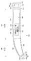
FIG. 1 is a diagram illustrating an example of an external configuration of a
図1に示すように、体内水分計100は本体部110と挿入部120とを備える。本体部110は、上面114、下面115、側面116、117がそれぞれ長軸方向(不図示)に略平行に形成されており、全体として、直線状に形成されている。また、本体部110の筐体表面には、各種ユーザインターフェースが配置され、筐体内部には体内の水分量を算出するための電子回路が収納されている。 As shown in FIG. 1, the in-
図1の例では、ユーザインターフェースとして、電源スイッチ111及び表示部112が示されている。電源スイッチ111は、本体部110の後端面113の凹部に配されている。このように凹部に電源スイッチ111を配する構成とすることで、電源スイッチ111の誤操作を防ぐことができる。なお、電源スイッチ111がオンされると後述の電源部211(図2)から体内水分計100の各部への電源供給が開始され、体内水分計100は動作状態となる。 In the example of FIG. 1, a
表示部112は、本体部110の側面117上において、長軸方向のやや前方側に配されている。これは、体内水分計100を用いて被検者の体内水分量を測定するにあたり、測定者が把持領域118を把持した場合であっても、測定者の把持した手で表示部112が完全に覆われることがないようにするためである(把持した状態でも測定結果が視認できるようにするためである)。 The
表示部112には、今回の水分量の測定結果131が表示される。また、参考として前回の測定結果132もあわせて表示される。さらに、電池表示部133には、電池(図2の電源部211)の残量が表示される。また、無効な測定結果が得られた場合や測定エラーが検出された場合には、表示部112に“E”が表示され、その旨がユーザに報知される。なお、表示部112に表示される文字等は、本体部110の上面114側を上とし、下面115側を下として、表示されるものとする。 The
体内水分計100の挿入部120は、上面124及び下面125が曲面形状を有しており、本体部110に対して、全体として、下向きに緩やかに湾曲している。挿入部120の先端面122には、検出部121がスライド可能に保持されている。 The
検出部121は、先端面122に略平行な面を有するセンサ部123を有しており、センサ部123の皮膚への密着を保証する上での押圧を確保するため、不図示のばねにより、矢印141bの方向へ付勢されている(たとえば150gf程度の付勢力)。そして、センサ部123が被検者の腋窩の皮膚に押し当てられると、検出部121が矢印141aの方向(先端面122と略直交する方向、すなわち先端面122の法線方向)に所定量(例えば1mm〜10mm、本実施形態では5mm)スライドし、これにより測定が開始されるよう構成されている(以下、矢印141aの方向をスライド方向と称す)。 The
具体的には、ユーザが電源スイッチ111をオンして体内水分計100を動作状態とした後、センサ部123を被検者の腋窩に所定時間以上(例えば2秒以上)押し当てられたことが検知されると、体内水分量の測定が開始される。あるいは、ユーザが電源スイッチ111をオンして体内水分計100を動作状態とした後、センサ部123を被検者の腋窩に所定負荷(例えば20gf〜200gf、さらに好ましくは100gf〜190gf、本実施形態では150gf)で押し当てたことが検知されると、体内水分量の測定が開始される。このような仕組みにより、測定時におけるセンサ部123の腋窩への密着の程度を一定にすることができる。 Specifically, after the user turns on the
なお、センサ部123の被検者との接触面には、電極が敷設されているが、センサ部123の詳細構成は後述するものとする。 In addition, although the electrode is laid in the contact surface with the subject of the
<2.体内水分計の機能構成>
図2は、本実施形態に係る体内水分計100の機能構成例を示すブロック図である。図2において、制御部201は、CPU202、メモリ203を有し、CPU202はメモリ203に格納されているプログラムを実行することにより、体内水分計100における種々の制御を実行する。<2. Functional configuration of body moisture meter>
FIG. 2 is a block diagram showing a functional configuration example of the
例えば、CPU202は、図7のフローチャートにより後述する表示部112の表示制御、ブザー222やLEDランプ223の駆動制御、体内水分量の測定(本実施形態では静電容量測定)などを実行する。メモリ203は、不揮発性メモリと揮発性メモリとを含み、不揮発性メモリはプログラムメモリとして、揮発性メモリはCPU202の作業メモリとして利用される。 For example, the
電源部211は、交換が可能なバッテリー、或いは充電が可能なバッテリーを有しており、体内水分計100の各部へ電源を供給する。電圧レギュレータ212は、制御部201等へ一定電圧(例えば、2.3V)を供給する。電池残量検出部213は、電源部211から供給される電圧値に基づいて、電池の残量を検出し、その検出結果を制御部201に通知する。制御部201は、電池残量検出部213からの電池残量検出信号に基づいて、電池表示部133の表示を制御する。 The
電源スイッチ111が押下されると、各部への電源部211からの電力供給が開始される。そして、制御部201は、電源スイッチ111のユーザによる押下が1秒以上継続したことを検出すると、電源部211からの各部への電源供給を維持させ、体内水分計100を動作状態とする。上述したように、測定スイッチ214は、検出部121が矢印141aの方向へ所定量以上押されるとオン状態になる。制御部201は、測定スイッチ214のオン状態が所定時間(例えば2秒)継続すると、水分量の測定を開始する。なお、電源部211の消耗を防止するために、体内水分計100が動作状態になってから5分経過しても測定開始とならない場合は、制御部201は自動的に体内水分計100を電源オフの状態へと移行させる。 When the
測定回路221は、センサ部123と接続され、静電容量を測定する。図3は、測定回路221の構成例を示す図である。図3に示すように、インバータ301、302、抵抗303、304、被検者容量310によりCR発振回路が形成される。被検者容量310によって出力信号305の発振周波数が変化するので、制御部201は、出力信号305の周波数を測定することにより、被検者容量310を算出する。なお、本実施形態のセンサ部123は、2つの櫛形の電極が、それぞれの櫛歯が互い違いに並ぶように配置されてなるものとする。 The
図2に戻る。表示部112は、図1で説明したような表示を制御部201の制御下で行う。ブザー222は、検出部121の押下による測定の開始や、体内水分量の測定が完了した際に鳴動し、測定の開始や完了をユーザに通知する。LEDランプ223もブザー222と同様の通知を行う。すなわち、LEDランプ223は、検出部121の押下による測定の開始や、体内水分量の測定が完了した際に点灯し、測定の開始や完了をユーザに通知する。計時部224は、電源がオフの状態であっても電源部211からの電源供給を受けて動作し、動作状態においては時刻を制御部201に通知する。 Returning to FIG. The
<3.センサ部の接触面の電極配置>
次にセンサ部123の電極配置について図4を用いて説明する。図4は、センサ部123の接触面における電極配置を説明するための図である。図4に示すように、本実施形態に係る体内水分計100では、センサ部123に、表裏に配線可能なプリント基板(縦8〜12mm、好ましくは11mm、横5〜8mm、好ましくは8mmのガラスエポキシ基板)400が配されており、当該プリント基板400上に櫛形電極410と櫛形電極420とが、それぞれの櫛歯が互い違いに並ぶように配置されている。<3. Electrode arrangement on contact surface of sensor section>
Next, the electrode arrangement of the
櫛形電極410及び420は、それぞれ、櫛歯部411、421と、長辺部412、422とから構成されており、本実施形態において櫛形電極410の長辺部412と櫛形電極420の長辺部422とは、4〜6mm、好ましくは6mmの間隔で配置されている。 The
なお、図4の例では、櫛形電極410及び420はそれぞれ、櫛歯が9本配された場合について示しているが、本発明はこれに限定されず、4本から16本の間であればよく、好適には、6本であることが望ましい。 In the example of FIG. 4, each of the comb-shaped
このように、最適な櫛歯の数を有する櫛形電極410及び420を配することで、被検者の腋窩にて体内水分量を精度よく測定することができる。 Thus, by arranging the comb-shaped
<4.センサ部の電極配置の詳細>
次に、センサ部123の電極配置の更なる詳細について図5A、図5B及び図6A、図6Bを用いて説明する。図5Aは、図4の参照番号431に示す平面領域の詳細構成の一例を示す図であり、図6Bは、図4のA−A断面の詳細構成の一例を示す図である。<4. Details of sensor electrode arrangement>
Next, further details of the electrode arrangement of the
はじめに、平面領域431の詳細構成の一例について説明する。図5Aに示すように、櫛形電極410及び420は、それぞれの櫛歯の幅(a)が0.4mmであり、長さ(b)が5mmに構成されている。上述したように、櫛形電極410の長辺部412と櫛形電極420の長辺部422との間隔は6mmであることから、櫛形電極420の櫛歯の先端から、櫛形電極410の長辺部412の中心線までの距離(c)は、0.6mmとなっている。 First, an example of a detailed configuration of the
また、櫛形電極410及び410のそれぞれの櫛歯の間隔(d)は、1.2mmの等間隔で配置されており、櫛形電極410の各櫛歯は、対向する櫛形電極420の各櫛歯の間において、中央位置に配置されている。上述したように、櫛形電極410及び420の櫛歯は、幅(a)が0.4mmであるため、櫛形電極410の櫛歯と櫛形電極420の櫛歯との間隔(e)は、互いに、0.4mm間隔で隣接することとなる。 Further, the interval (d) between the comb teeth of the
なお、図5Aに示す電極配置は一例であり、例えば、図5Bに示す6パターンにより櫛形電極410及び420を構成・配置してもよい。ただし、櫛形電極410及び420の構成・配置は、体内水分量の測定精度に影響するものであり、後述するセンサ部123の断面構成のもとでは、図5Bに示す6パターンのうち、パターン4が最も適していることが実験的に求められている(パターン4は、所定の範囲内で水分量を変動させた場合の検出値の変動範囲が最も広く(変動率が最も大きく)、より高い分解能を実現できる)。 The electrode arrangement shown in FIG. 5A is an example. For example, the comb-shaped
続いて、センサ部123の断面構成について説明する。図6Aは、本実施形態に係る体内水分計100のセンサ部123の断面構成を説明するにあたり、比較対象として、一般的なプリント基板(表裏に配線可能なプリント基板)を用いてセンサ部を実現する場合の、2層基板と4層基板の例を示した図である。 Subsequently, a cross-sectional configuration of the
図6Aの(A)に示すように、2層基板によりセンサ部123を実現する場合、通常、プリント基板612の表面に電極613を配し、反対側の面(裏面)に電極613を印加するための配線614を配する。また、表面に配した電極613を保護するために、保護材611を塗布する。 As shown in FIG. 6A (A), when the
また、図6Aの(B)に示すように、4層基板によりセンサ部123を実現する場合、通常、プリント基板622の表面に電極613を配し、裏面およびプリント基板625の表裏面に、電極613を印加するための各種配線624を配する。また、プリント基板622の表面に配した電極613を保護するために、保護材621を塗布する。 Further, as shown in FIG. 6A (B), when the
そして、プリント基板622とプリント基板625とを、絶縁材626を介して積層することで、4層構造を実現する。 Then, the printed
このように、表裏に配線可能なプリント基板を用いてセンサ部を実現する場合、第1の層(プリント基板612の表面、あるいはプリント基板622の表面)に電極613を配し、その上に保護材621を塗布するのが一般的である。 As described above, when the sensor unit is realized by using a printed circuit board that can be wired on the front and back, the
しかしながら、このようにしてセンサ部123を構成した場合、保護材611または621が摩耗したり破損したりすることで、電極613の一部が剥き出しの状態となりやすく、そこから静電気が入った場合には、体内水分計100の内部の回路が破壊される恐れがある。このため、本実施形態に係る体内水分計100では、センサ部123を、図6Bに示すような断面構成を有するように構成した。 However, when the
図6Bは、本実施形態に係る体内水分計100のセンサ部123の断面構成を示す図である。 FIG. 6B is a diagram illustrating a cross-sectional configuration of the
図6Bにおいて、721は4層基板の第1の層及び第2の層を形成するプリント基板であり、表面(つまり、第1の層)には電極が配されておらず、裏面(つまり、第2の層)に電極613が配されている。 In FIG. 6B,
また、725は4層基板の第3の層及び第4の層を形成するプリント基板であり、表裏面(第3及び第4の層)には、電極613を印加するための各種配線724が配されている。
そして、プリント基板721とプリント基板725とを、絶縁材726を介して積層することで、4層構造を実現する。 Then, the printed
このように、本実施形態に係る体内水分計100では、センサ部123を4層基板により構成するにあたり、第2の層に電極613を配する構成とした。これにより、被検者の体内水分量を測定するにあたり、保護材と比較して耐摩耗性を有するプリント基板725の表面が被検者の体表面に接触することとなり、従来のように、保護材の摩耗や損傷により、電極613の一部が剥き出しの状態となることを回避させることが可能となる。 As described above, the in-
また、従来のように、保護材621を塗布する場合には、プリント基板612または622に対する保護材621の位置合わせが困難であったり、保護材621の厚さを均一にすることが困難であるといった製造上の短所があったところ、上記のようにプリント基板を積層するだけの製造工程の場合、製造が容易であり、製造コストも削減できるといった利点がある。 Further, as in the conventional case, when the
<5.体内水分計の動作>
以上のような構成を備えた、本実施形態に係る体内水分計100の動作を、図7のフローチャートを参照して説明する。<5. Operation of body moisture meter>
The operation of the
ステップS701では、制御部201が、測定開始の指示を検出する。本実施形態では、測定スイッチ214の状態を監視し、測定スイッチ214のオン状態が2秒以上継続した場合に測定開始の指示を検出したと判定する。制御部201は、測定開始の指示を検出すると、ステップS702において、測定回路221からの出力信号305の発振周波数を測定する。 In step S701, the
ステップS703では、ステップS702において測定された出力信号305の発振周波数に基づいて、被検者の体内水分量を算出する。 In step S703, the moisture content in the body of the subject is calculated based on the oscillation frequency of the
ステップS704では、ステップS703で算出された体内水分量が所定の閾値を超えるか否かに基づいて被検者が脱水状態か否かを判定する。なお、この場合の閾値とは、例えば、水を100%、空気を0%とした時の35%に相当する値が望ましい。 In step S704, it is determined whether or not the subject is dehydrated based on whether or not the amount of water in the body calculated in step S703 exceeds a predetermined threshold. The threshold value in this case is preferably a value corresponding to 35% when water is 100% and air is 0%.
ステップS705では、今回の測定情報をメモリ203に格納する。図8は、メモリ203に格納される測定情報のデータ構成を示す図である。図8において、測定値801は、今回の測定により算出された体内水分量である。判定結果802は、今回の測定により算出された体内水分量に対して、ステップS704において判定された、脱水状態か非脱水状態かを示す情報である。測定時刻803は、今回の測定において計時部224から通知された時刻を示す情報である。測定時刻803としては、例えば、ステップS702において測定を実行した時点で計時部224から通知されている時刻とすることができる。 In step S705, the current measurement information is stored in the
ステップS706では、今回の測定により算出された体内水分量を表示部112に表示する。このとき、脱水状態か非脱水状態かの判定結果に応じた表示形態により表示を行う(例えば、脱水状態の場合には、赤色にて体内水分量を表示し、非脱水状態の場合には、青色にて体内水分量を表示する)。 In step S706, the water content in the body calculated by the current measurement is displayed on the
以上の説明から明らかなように、本実施形態に係る体内水分計100は、センサ部123の耐摩耗性の向上と製造コストの低減を両立させるべく、
・プリント基板を用いた4層構造とした。
・4層基板の第1の層には電極を配置せず、第2の層に電極を配置する構成とした。
・電極を印加するための配線を、第3または第4の層に配置する構成とした。As is clear from the above description, the
-A four-layer structure using a printed circuit board.
-It was set as the structure which arrange | positions an electrode in a 2nd layer, without arrange | positioning an electrode in the 1st layer of a 4-layer board | substrate.
The wiring for applying the electrode is arranged in the third or fourth layer.
また、測定精度を向上させるべく、
・第2の層の電極がプリント基板(ガラスエポキシ基板)を介して被検者の静電容量を測定するにあたり、最適な電極配置を実験的に求めた。
・縦11mm、横8mmのプリント基板に対して、櫛歯の数を4〜16本、櫛歯の幅を0.2〜0.8mm、櫛歯の間隔を0.2〜0.8mm、櫛歯の長さを4〜6mmとして櫛形電極を形成することで、被検者の体内水分量を測定可能であることわかった。
・更に、縦11mm、横8mmのプリント基板に対して、櫛歯の数を6本、櫛歯の幅を0.4mm、櫛歯の間隔を0.4mm、櫛歯の長さを4mmとして櫛形電極を形成することが最適であることがわかった。In addition, to improve the measurement accuracy,
-When the electrode of the second layer measured the capacitance of the subject through the printed board (glass epoxy board), the optimum electrode arrangement was experimentally determined.
・ 4 to 16 comb teeth, 0.2 to 0.8 mm comb width, 0.2 to 0.8 mm comb spacing, and 11 to 8 mm wide printed circuit board It was found that the moisture content in the body of the subject can be measured by forming the comb-shaped electrode with a tooth length of 4 to 6 mm.
・ Furthermore, for a printed circuit board of 11 mm in length and 8 mm in width, the number of comb teeth is 6, the width of the comb teeth is 0.4 mm, the distance between the comb teeth is 0.4 mm, and the length of the comb teeth is 4 mm. It has been found that forming an electrode is optimal.
[第2の実施形態]
上記第1の実施形態では、プリント基板を2段にして4層構造を形成した場合について説明したが、本発明はこれに限定されない。例えば、プリント基板を複数積層し、多層構造を形成した場合(プリント基板をn段として、2n層構造を形成した場合)においても同様である。[Second Embodiment]
In the first embodiment, the case where the printed circuit board is formed in two stages to form a four-layer structure has been described, but the present invention is not limited to this. For example, the same applies to the case where a plurality of printed circuit boards are stacked to form a multilayer structure (when the printed circuit board has n stages and a 2n layer structure is formed).
つまり、第1の段のプリント基板の表面(第1の層)には、電極を配置せず、第1の段のプリント基板の裏面(第2の層)に電極を配置することで、センサ部123を形成することで、上記第1の実施形態と同様の効果が得られる。 That is, the electrode is not disposed on the surface (first layer) of the first-stage printed circuit board, but the electrode is disposed on the back surface (second layer) of the first-stage printed circuit board. By forming the
また、上記第1の実施形態では、プリント基板721の厚さについて言及しなかったが、プリント基板721の厚さは、例えば、0.6〜1.5mmであることが望ましく、好適には、1.2mmであることが好ましい。 In the first embodiment, the thickness of the printed
100:体内水分計、110:本体部、111:電源スイッチ、112:表示部、113:後端面、114:上面、115:下面、116:側面、117:側面、118:把持領域、120:挿入部、121:検出部、122:先端面、123:センサ部、124:上面、125:下面、400:プリント基板、410:櫛形電極、411:櫛歯部、412:長辺部、420:櫛形電極、421:櫛歯部、422:長辺部、611:保護材、612:プリント基板、613:電極、614:配線、621:保護材、622:プリント基板、624:配線、625:プリント基板、626:絶縁材、721:プリント基板、724:配線、725:プリント基板、726:絶縁材DESCRIPTION OF SYMBOLS 100: Body moisture meter, 110: Main body part, 111: Power switch, 112: Display part, 113: Rear end surface, 114: Upper surface, 115: Lower surface, 116: Side surface, 117: Side surface, 118: Grasping area, 120: Insertion Part: 121: detection part, 122: tip face, 123: sensor part, 124: top face, 125: bottom face, 400: printed circuit board, 410: comb electrode, 411: comb tooth part, 412: long side part, 420: comb form Electrode, 421: comb-tooth portion, 422: long side portion, 611: protective material, 612: printed board, 613: electrode, 614: wiring, 621: protective material, 622: printed board, 624: wiring, 625: printed board 626: Insulating material 721: Printed circuit board 724: Wiring 725: Printed circuit board 726: Insulating material
Claims (7)
Translated fromJapanese前記複数積層されたプリント基板のうち、被検者の体表面に接触する第1の面を有する第1の段に配されたプリント基板は、該第1の面と反対側の第2の面に、被検者の体表面の静電容量を測定するための2つの櫛形の電極が、それぞれの櫛歯が互い違いになるように配置されており、かつ、
前記2つの櫛形の電極は、それぞれ、幅が0.2mm〜0.8mm、長さが4mm〜6mmの櫛歯が、0.2mm〜0.8mmの間隔で6本配されてなることを特徴とするセンサ。A sensor composed of a multilayer structure in which a plurality of printed circuit boards that can be wired on the front and back are laminated,
Of the plurality of stacked printed circuit boards, the printed circuit board arranged on the first stage having the first surface that contacts the body surface of the subject is the second surface opposite to the first surface. In addition, two comb-shaped electrodes for measuring the capacitance of the body surface of the subject are arranged so that the respective comb teeth are staggered, and
Each of the two comb-shaped electrodes has six comb teeth each having a width of 0.2 mm to 0.8 mm and a length of 4 mm to 6 mm arranged at intervals of 0.2 mm to 0.8 mm. Sensor.
Priority Applications (2)
| Application Number | Priority Date | Filing Date | Title |
|---|---|---|---|
| JP2012053658AJP2015097546A (en) | 2012-03-09 | 2012-03-09 | Body moisture meter and sensor |
| PCT/JP2013/000869WO2013132757A1 (en) | 2012-03-09 | 2013-02-18 | Body water content meter and sensor |
Applications Claiming Priority (1)
| Application Number | Priority Date | Filing Date | Title |
|---|---|---|---|
| JP2012053658AJP2015097546A (en) | 2012-03-09 | 2012-03-09 | Body moisture meter and sensor |
Publications (1)
| Publication Number | Publication Date |
|---|---|
| JP2015097546Atrue JP2015097546A (en) | 2015-05-28 |
Family
ID=49116253
Family Applications (1)
| Application Number | Title | Priority Date | Filing Date |
|---|---|---|---|
| JP2012053658APendingJP2015097546A (en) | 2012-03-09 | 2012-03-09 | Body moisture meter and sensor |
Country Status (2)
| Country | Link |
|---|---|
| JP (1) | JP2015097546A (en) |
| WO (1) | WO2013132757A1 (en) |
Cited By (2)
| Publication number | Priority date | Publication date | Assignee | Title |
|---|---|---|---|---|
| JP2017527344A (en)* | 2014-08-06 | 2017-09-21 | ヴェリリー ライフ サイエンシズ エルエルシー | Single electrode sharing in skin resistance and capacitance measurements |
| US20180299397A1 (en)* | 2017-04-13 | 2018-10-18 | Hitachi, Ltd. | Humidity sensing element and hygrometer |
Family Cites Families (4)
| Publication number | Priority date | Publication date | Assignee | Title |
|---|---|---|---|---|
| JP3453962B2 (en)* | 1995-10-31 | 2003-10-06 | 松下電工株式会社 | Capacitive rain sensor |
| JPH11318845A (en)* | 1998-05-14 | 1999-11-24 | Ya Man Ltd | Corporal water content estimating device |
| JP2009089869A (en)* | 2007-10-09 | 2009-04-30 | Moritex Corp | Capacitive moisture sensor and manufacturing method thereof |
| WO2011016407A1 (en)* | 2009-08-03 | 2011-02-10 | 日本電気株式会社 | Biological information detector, biological information detection method, and mobile terminal |
- 2012
- 2012-03-09JPJP2012053658Apatent/JP2015097546A/enactivePending
- 2013
- 2013-02-18WOPCT/JP2013/000869patent/WO2013132757A1/enactiveApplication Filing
Cited By (5)
| Publication number | Priority date | Publication date | Assignee | Title |
|---|---|---|---|---|
| JP2017527344A (en)* | 2014-08-06 | 2017-09-21 | ヴェリリー ライフ サイエンシズ エルエルシー | Single electrode sharing in skin resistance and capacitance measurements |
| US20180299397A1 (en)* | 2017-04-13 | 2018-10-18 | Hitachi, Ltd. | Humidity sensing element and hygrometer |
| JP2018179757A (en)* | 2017-04-13 | 2018-11-15 | 株式会社日立製作所 | Humidity detection element and hygrometer |
| US10859524B2 (en)* | 2017-04-13 | 2020-12-08 | Hitachi, Ltd. | Humidity sensing element and hygrometer |
| JP7029884B2 (en) | 2017-04-13 | 2022-03-04 | 株式会社日立製作所 | Humidity detection element and hygrometer |
Also Published As
| Publication number | Publication date |
|---|---|
| WO2013132757A1 (en) | 2013-09-12 |
Similar Documents
| Publication | Publication Date | Title |
|---|---|---|
| JP5993014B2 (en) | Body moisture meter | |
| CN102481109B (en) | Body Fat Measuring Device | |
| JP2006145540A (en) | Scale capable of measuring pulse and heartbeat | |
| US10206621B2 (en) | Instrumented wearable device for measurement of physiological parameters | |
| JP5883151B2 (en) | Body moisture meter and display control method | |
| KR20160046616A (en) | Apparatus and method for measuring body fat | |
| JP2023056003A5 (en) | ||
| WO2013132757A1 (en) | Body water content meter and sensor | |
| JP5917911B2 (en) | Body moisture meter and display control method | |
| CN100377688C (en) | body composition measurement device | |
| JP2000023936A (en) | Health management guide advising device | |
| WO2013136659A1 (en) | Body water meter | |
| JP5993013B2 (en) | Body moisture meter, body moisture meter control method, and storage medium | |
| JP5859846B2 (en) | Body moisture meter | |
| JP5883150B2 (en) | Body moisture meter and display control method | |
| JP6018058B2 (en) | Body moisture meter and method of operating the same | |
| JP2013192650A (en) | Intracorporeal moisture meter | |
| JP6117101B2 (en) | Body moisture meter and display control method thereof | |
| JP2013027431A (en) | Body moisture meter and method for controlling the same | |
| JP2013132517A (en) | Body moisture meter | |
| JP2002253522A (en) | Bioelectrical impedance measuring device | |
| JP7436458B2 (en) | Appliances, measurement systems and determination methods | |
| JP7594435B2 (en) | Bite force sensor sheet | |
| WO2014049631A1 (en) | Body-water-content meter | |
| JP2002010988A5 (en) |