JP2015084787A - Movement monitoring device - Google Patents
Movement monitoring deviceDownload PDFInfo
- Publication number
- JP2015084787A JP2015084787AJP2013223007AJP2013223007AJP2015084787AJP 2015084787 AJP2015084787 AJP 2015084787AJP 2013223007 AJP2013223007 AJP 2013223007AJP 2013223007 AJP2013223007 AJP 2013223007AJP 2015084787 AJP2015084787 AJP 2015084787A
- Authority
- JP
- Japan
- Prior art keywords
- unit
- user
- displacement information
- notification
- movement
- Prior art date
- Legal status (The legal status is an assumption and is not a legal conclusion. Google has not performed a legal analysis and makes no representation as to the accuracy of the status listed.)
- Pending
Links
- 230000033001locomotionEffects0.000titleclaimsabstractdescription160
- 238000012806monitoring deviceMethods0.000titleclaimsabstractdescription33
- 238000006073displacement reactionMethods0.000claimsabstractdescription85
- 238000001514detection methodMethods0.000claimsabstractdescription57
- 230000001133accelerationEffects0.000claimsabstractdescription50
- 238000012544monitoring processMethods0.000claimsdescription30
- 230000010365information processingEffects0.000abstractdescription55
- 238000004891communicationMethods0.000description27
- 238000000034methodMethods0.000description16
- 230000008569processEffects0.000description11
- 238000010586diagramMethods0.000description9
- 239000000463materialSubstances0.000description7
- 239000010453quartzSubstances0.000description6
- VYPSYNLAJGMNEJ-UHFFFAOYSA-Nsilicon dioxideInorganic materialsO=[Si]=OVYPSYNLAJGMNEJ-UHFFFAOYSA-N0.000description6
- 230000005540biological transmissionEffects0.000description5
- 239000000853adhesiveSubstances0.000description4
- 230000001070adhesive effectEffects0.000description4
- 230000008859changeEffects0.000description4
- 238000012986modificationMethods0.000description4
- 230000004048modificationEffects0.000description4
- 230000000638stimulationEffects0.000description4
- 206010038743RestlessnessDiseases0.000description3
- 239000000919ceramicSubstances0.000description3
- 230000000694effectsEffects0.000description3
- 230000010354integrationEffects0.000description3
- XKRFYHLGVUSROY-UHFFFAOYSA-NArgonChemical compound[Ar]XKRFYHLGVUSROY-UHFFFAOYSA-N0.000description2
- IJGRMHOSHXDMSA-UHFFFAOYSA-NAtomic nitrogenChemical compoundN#NIJGRMHOSHXDMSA-UHFFFAOYSA-N0.000description2
- 125000002066L-histidyl groupChemical group[H]N1C([H])=NC(C([H])([H])[C@](C(=O)[*])([H])N([H])[H])=C1[H]0.000description2
- 238000005530etchingMethods0.000description2
- 230000005284excitationEffects0.000description2
- 239000000284extractSubstances0.000description2
- 229910000833kovarInorganic materials0.000description2
- NJPPVKZQTLUDBO-UHFFFAOYSA-NnovaluronChemical compoundC1=C(Cl)C(OC(F)(F)C(OC(F)(F)F)F)=CC=C1NC(=O)NC(=O)C1=C(F)C=CC=C1FNJPPVKZQTLUDBO-UHFFFAOYSA-N0.000description2
- TWNQGVIAIRXVLR-UHFFFAOYSA-Noxo(oxoalumanyloxy)alumaneChemical compoundO=[Al]O[Al]=OTWNQGVIAIRXVLR-UHFFFAOYSA-N0.000description2
- 238000012545processingMethods0.000description2
- 238000007789sealingMethods0.000description2
- 239000003566sealing materialSubstances0.000description2
- 238000012360testing methodMethods0.000description2
- 238000012546transferMethods0.000description2
- LFQSCWFLJHTTHZ-UHFFFAOYSA-NEthanolChemical compoundCCOLFQSCWFLJHTTHZ-UHFFFAOYSA-N0.000description1
- 206010041347SomnambulismDiseases0.000description1
- 238000013459approachMethods0.000description1
- 229910052786argonInorganic materials0.000description1
- 230000008901benefitEffects0.000description1
- 238000012790confirmationMethods0.000description1
- 239000000470constituentSubstances0.000description1
- 239000013078crystalSubstances0.000description1
- 238000003745diagnosisMethods0.000description1
- 201000010099diseaseDiseases0.000description1
- 208000037265diseases, disorders, signs and symptomsDiseases0.000description1
- 230000035622drinkingEffects0.000description1
- 238000010304firingMethods0.000description1
- 239000011521glassSubstances0.000description1
- 230000005484gravityEffects0.000description1
- 239000001307heliumSubstances0.000description1
- 229910052734heliumInorganic materials0.000description1
- SWQJXJOGLNCZEY-UHFFFAOYSA-Nhelium atomChemical compound[He]SWQJXJOGLNCZEY-UHFFFAOYSA-N0.000description1
- 239000011261inert gasSubstances0.000description1
- 229910052751metalInorganic materials0.000description1
- 239000002184metalSubstances0.000description1
- 230000036651moodEffects0.000description1
- 229910052757nitrogenInorganic materials0.000description1
- 230000010355oscillationEffects0.000description1
- 238000000059patterningMethods0.000description1
- 230000000149penetrating effectEffects0.000description1
- 238000000206photolithographyMethods0.000description1
- 238000000554physical therapyMethods0.000description1
- 230000029058respiratory gaseous exchangeEffects0.000description1
- 238000010079rubber tappingMethods0.000description1
- 230000036421sense of balanceEffects0.000description1
- 229910052710siliconInorganic materials0.000description1
- 239000010703siliconSubstances0.000description1
- 230000006641stabilisationEffects0.000description1
- 238000011105stabilizationMethods0.000description1
- 229910001220stainless steelInorganic materials0.000description1
- 239000010935stainless steelSubstances0.000description1
- 239000000758substrateSubstances0.000description1
- 208000024891symptomDiseases0.000description1
- 238000012549trainingMethods0.000description1
Images


Classifications
- G—PHYSICS
- G08—SIGNALLING
- G08B—SIGNALLING OR CALLING SYSTEMS; ORDER TELEGRAPHS; ALARM SYSTEMS
- G08B21/00—Alarms responsive to a single specified undesired or abnormal condition and not otherwise provided for
- G08B21/18—Status alarms
Landscapes
- Business, Economics & Management (AREA)
- Emergency Management (AREA)
- Physics & Mathematics (AREA)
- General Physics & Mathematics (AREA)
- Measurement Of The Respiration, Hearing Ability, Form, And Blood Characteristics Of Living Organisms (AREA)
Abstract
Translated fromJapaneseDescription
Translated fromJapanese本発明は、動き監視装置に関する。 The present invention relates to a motion monitoring apparatus.
従来、身体の動作を、センサーを用いて検出する様々な装置が提供されている。たとえば、下記の特許文献1では、検出手段を有した台座(座布団)で座禅者の動作を検出し、それに基づいて、座禅者に刺激や警告を与える座禅ゲーム装置を提案している。 2. Description of the Related Art Conventionally, various devices for detecting body movement using sensors have been provided. For example,
しかしながら、特許文献1で提案されている座禅ゲーム装置は、座禅者が座ることのできる台座、および座禅者に警告を与える叩き手段、または座禅者が座ることのできる座布団を有しているため、装置としては、大掛かりなものになる。また、座禅ゲームを行うまでに装置の組立などの作業が必要となるために、使いやすさに欠けるという課題があった。 However, since the zazen game device proposed in
本発明は、上述の課題の少なくとも一部を解決するためになされたものであり、以下の形態または適用例として実現することが可能である。 SUMMARY An advantage of some aspects of the invention is to solve at least a part of the problems described above, and the invention can be implemented as the following forms or application examples.
[適用例1]本適用例にかかる動き監視装置は、加速度を検出し、検出データを出力する加速度検出部と、前記検出データを用いて変位情報を演算する演算部と、前記変位情報に基づいて動きの有無を判定する判定部と、前記判定に基づき、報知信号を前記報知部に送信する報知信号出力部と、受信した前記報知信号に基づいて被験者に報知する報知手段と、を有することを特徴とする。 Application Example 1 A motion monitoring apparatus according to this application example is based on an acceleration detection unit that detects acceleration and outputs detection data, a calculation unit that calculates displacement information using the detection data, and the displacement information. A determination unit that determines the presence or absence of movement, a notification signal output unit that transmits a notification signal to the notification unit based on the determination, and a notification unit that notifies the subject based on the received notification signal. It is characterized by.
このような動き監視装置によれば、センサー部と、報知部と、情報処理部と、を備え、センサー部において、センサー部の加速度を検出し、変位情報に変換して情報処理部に送信する。情報処理部は、センサー部の変位情報に基づいて動きの有無を判定し、判定に基づき報知信号を報知部に送信する。報知部は、受信した報知信号に基づいて被験者に報知することができる。これにより、動き監視装置は、小さく、かつ少ない構成部材で動きを監視し、報知ができるため、小型化でき、可搬性があり利便性が向上する。 According to such a motion monitoring device, the sensor unit, the notification unit, and the information processing unit are provided. The sensor unit detects the acceleration of the sensor unit, converts it into displacement information, and transmits the displacement information to the information processing unit. . The information processing unit determines the presence or absence of movement based on the displacement information of the sensor unit, and transmits a notification signal to the notification unit based on the determination. The notification unit can notify the subject based on the received notification signal. Thereby, since a motion monitoring apparatus can monitor a motion with small and few structural members and can alert | report, it can reduce in size, it is portable, and the convenience improves.
[適用例2]上記適用例にかかる動き監視装置において、前記判定部は、前記変位情報が、閾値を超えているか否かによって動きの有無を判定する、ことを特徴とする。 Application Example 2 In the motion monitoring apparatus according to the application example described above, the determination unit determines whether or not there is a motion based on whether or not the displacement information exceeds a threshold value.
このような動き監視装置によれば、判定部により、変位情報が所定の閾値を超えているか否かによって動きの有無を判定し、判定に基づき報知手段を用いて報知することで、動きがわかりやすく、より監視しやすくすることができる。 According to such a motion monitoring device, the determination unit determines the presence or absence of motion based on whether or not the displacement information exceeds a predetermined threshold value, and notifies the motion using the notification means based on the determination, so that the motion is understood. It can be made easier and easier to monitor.
[適用例3]上記適用例にかかる動き監視装置において、前記判定部は、前記変位情報が、あらかじめ測定された変位情報と同じか否かによって動きの有無を判定する、ことを特徴とする。 Application Example 3 In the motion monitoring apparatus according to the application example described above, the determination unit determines whether or not there is a motion based on whether or not the displacement information is the same as the displacement information measured in advance.
このような動き監視装置によれば、判定部により、変位情報が、あらかじめ測定された変位情報と異なることによって動きの有無を判定し、判定に基づき報知手段を用いて報知することで、動きがわかりやすく、より監視しやすくすることができる。 According to such a motion monitoring device, the determination unit determines the presence or absence of movement by determining that the displacement information is different from the displacement information measured in advance, and using the notification means based on the determination, the movement is detected. It is easy to understand and can be monitored more easily.
[適用例4]上記適用例にかかる動き監視装置において、前記加速度検出部は、被験者および被験者が着用する衣類の少なくとも一方に装着される、ことを特徴とする。 Application Example 4 In the motion monitoring device according to the application example, the acceleration detection unit is attached to at least one of a subject and clothing worn by the subject.
このような動き監視装置によれば、加速度検出部が被験者、および被験者が着用する衣類の少なくとも一方に装着されることで、被験者の加速度を検出し、被験者に動きの有無を報知することができる。これにより、動き監視装置は、小さく、かつ少ない構成部材で動きを監視し、報知ができるため、小型化でき、可搬性があり利便性が向上する。 According to such a motion monitoring device, the acceleration detection unit is attached to at least one of the subject and the clothing worn by the subject, so that the acceleration of the subject can be detected and the subject can be notified of the presence or absence of movement. . Thereby, since a motion monitoring apparatus can monitor a motion with small and few structural members and can alert | report, it can reduce in size, it is portable, and the convenience improves.
[適用例5]上記適用例にかかる動き監視装置において、前記判定部は、前記演算部が前記検出データを二回積分して変位情報を算出し、求められた前記変位情報が前記閾値を超えているか否かによって動きの有無を判定する、ことを特徴とする。 Application Example 5 In the motion monitoring apparatus according to the application example, the determination unit calculates displacement information by the calculation unit integrating the detection data twice, and the obtained displacement information exceeds the threshold value. It is characterized by determining the presence or absence of movement according to whether or not it is.
このような動き監視装置によれば、判定部により、検出データを二回積分し、変位情報に変換する。その変位情報が、所定の閾値を超えているかによって動きの有無を判定し、判定に基づき報知手段を用いて報知することで、動きがわかりやすく、より監視しやすくすることができる。 According to such a motion monitoring device, the determination unit integrates the detection data twice and converts it into displacement information. By determining the presence or absence of movement based on whether the displacement information exceeds a predetermined threshold and notifying using the notification means based on the determination, the movement can be easily understood and monitored more easily.
以下、本発明の実施形態について、図面を参照して説明する。なお、以下の各図においては、各層や各部材を認識可能な程度の大きさにするため、各層や各部材の尺度を実際とは異ならせしめている。 Hereinafter, embodiments of the present invention will be described with reference to the drawings. In the following drawings, the scale of each layer and each member is made different from the actual scale so that each layer and each member can be recognized.
(第1実施形態)
本実施形態にかかる動き監視装置の概略構成について説明する。
図1は、本実施形態の動き監視装置1の構成例を示す図である。図1では、互いに直交する3つの軸として、x軸、y軸、z軸を図示している。(First embodiment)
A schematic configuration of the motion monitoring apparatus according to the present embodiment will be described.
FIG. 1 is a diagram illustrating a configuration example of a
動き監視装置1は、被験者であるユーザーM1が座った状態において、ユーザーM1の頭部に取り付けられたセンサー部10と、情報処理部20と、ユーザーM1の腕部に取り付けられた報知部30とを含んで構成されている。
情報処理部20は、センサー部10、および報知部30と、通信部12,22,32(図2、図3、図5参照)を介して無線通信で接続することが可能であり、センサー部10から送信されたデータを受信することができる。また、報知部30は、情報処理部20から送信されたデータを受信することができる。なお、センサー部10、および報知部30と、情報処理部20との接続は、無線通信に限らない。The
The
ユーザーM1に取り付けられるセンサー部10の位置は、頭部に限らず、例えば、腰部、胸部、またはユーザーM1の装着品(衣類)等であってもよい。また、ユーザーM1に取り付けられる報知部30の位置は、腕部に限らず、例えば、頭部、頸部、またはユーザーM1の装着品等であってもよい。
本実施形態では、ユーザーM1にセンサー部10が取り付けられているが、センサー部10は、ユーザーM1、およびユーザーM1の装着品の少なくとも(いずれか)一方に取り付けられていればよい。The position of the
In the present embodiment, the
動き監視装置1では、センサー部10に備えられたセンサー(加速度検出部11(図2))によってユーザーM1の動き(加速度)を検出し、検出された検出データを情報処理部20に送信する。そして、情報処理部20は、受信した検出データに基づいて、ユーザーM1の動きの有無を判定し、判定に基づきユーザーM1の動きを、例えば、ディスプレイ等に表示したり、報知部30に報知信号を送信したりする。報知信号を受信した報知部30は、ユーザーM1の動きを報知手段により報知する。このような動き監視装置1によって、ユーザーM1の動きを監視し、報知することができる。 In the
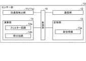
次に、センサー部10の構成について説明する。
図2は、センサー部10の構成を示すブロック図である。図に示すように、センサー部10は、加速度検出部11、通信部12、記憶部13、演算部14、制御部18等により構成されている。Next, the configuration of the
FIG. 2 is a block diagram illustrating a configuration of the
加速度検出部11は、センサー部10が取り付けられているユーザーM1の動き、すなわち加速度を検出するセンサーである。本実施形態では、座った状態にあるユーザーM1の頭部の動き(加速度)をセンサー部10が検出し、検出された検出データを情報処理部20に送信している。なお、本実施形態では、加速度検出部11は、二軸(x軸、y軸)方向の加速度が検出可能なセンサーである。また、加速度検出部11は、三軸方向以上(複数軸)の加速度が検出可能なセンサーであってもよい。
なお、加速度検出部11については、後述する。The
The
演算部14は、加速度の検出データからノイズを除去するHPF(High Pass Filter)等のフィルター回路14aと、検出データを二回積分して変位に変換する積分回路14bと、を備えている。つまり、演算部14は、加速度検出部11で検出された検出データからノイズを除去し、加速度を変位(移動量)に変換する処理を行うことで、センサー部10の移動量、言い換えるとユーザーM1の頭部の移動量である変位情報13aを求めることができる。そして、変位情報13aは、記憶部13に記憶される。 The
記憶部13は、例えばハードディスクのような外部記憶装置であり、センサー部10における各種データが記憶される。 The
通信部12は、情報処理部20と通信が可能な図示しない送信部、および受信部を備えている。通信部12は、演算部14で得られた変位情報13aを、通信部12を介して情報処理部20に送信する。 The
制御部18は、図示しないCPU(Central Processing Unit)、RAM(Random Access Memory)、およびROM(Read Only Memory)等を備え、センサー部10における各部を統括的に制御する。 The
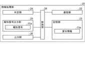
次に、情報処理部20の構成について説明する。
図3は、情報処理部20の構成を示すブロック図である。図に示すように、情報処理部20は、通信部22、記憶部23、判定部24、報知信号出力部25、出力部26、制御部28等により構成されている。Next, the configuration of the
FIG. 3 is a block diagram illustrating a configuration of the
通信部22は、センサー部10、および報知部30と送受信が可能な図示しない送信部、および受信部を備えている。通信部22は、センサー部10から送信された変位情報13aを受信し、変位情報23aとして記憶部23に記憶する。 The
記憶部23は、例えばハードディスクのような外部記憶装置であり、情報処理部20における各種データが記憶される。 The
判定部24は、記憶部23に記憶されている変位情報23aが、所定の閾値S1の範囲内にあるかを判定する。すなわち、ユーザーM1の頭部の位置が閾値S1の範囲内にあるか否かによって動きの有無を判定する。
閾値S1は、変位情報23aの始点を中心にして、x,y方向に形成された略円形の円内を範囲として設定されている。The
The threshold value S1 is set as a range within a substantially circular circle formed in the x and y directions with the start point of the
ここで、ユーザーM1の動きの有無を判定する例について図4を参照して説明する。
図4は、ユーザーM1(不図示)の頭部に取り付けられたセンサー部10を+z軸方向から見た、変位情報23aの例を示す図である。図4(a)、(b)は、x軸とy軸方向(二軸方向)の変位情報23aの移動量を表している。Here, an example of determining whether or not the user M1 moves is described with reference to FIG.
FIG. 4 is a diagram illustrating an example of the
判定部24は、図4に示すような、変位情報23aと閾値S1とを判定材料にして、ユーザーM1の動きの有無を判定する。
判定部24は、変位情報23aが閾値S1の範囲内(略円形の円内方向)にあれば(図4(a))、ユーザーM1の動きが小さい(動きが無い)と判定し、変位情報23aが閾値S1の範囲外(略円形の円外方向)にあれば(図4(b))、ユーザーM1の動きが大きい(動きが有る)と判定する。なお、閾値S1の範囲の設定は、ユーザーによって変更することができる。たとえば、センサー部10の動きが小さいユーザーは、閾値S1の範囲を狭く設定してもよいし、センサー部10の動きが大きいユーザーは、閾値S1の範囲を広げて設定してもよい。The
The
報知信号出力部25は、報知信号25aを、通信部22を介して報知部30に送信する。具体的には、報知信号出力部25は、ユーザーM1の動きが大きいと判定した場合、つまり上述した変位情報23aが閾値S1の範囲外にあるとき、報知信号25aを、通信部22を介して報知部30に送信する。
報知信号25aを報知部30に送信するタイミングは、たとえば、変位情報23aが閾値S1の範囲外に出た回数を記憶し、所定の回数に達したときや、所定の回数を超えたときに送信する。また、変位情報23aの移動量が著しく大きいときに、報知信号25aを送信してもよい。The notification
The timing at which the
出力部26は、ユーザーM1の動きに基づいて、図示しないディスプレイ等に、ユーザーM1の動き(図4)を表示する。動きを表示することで、ユーザーM1に、自身の動きを認識させることができる。 The
制御部28は、図示しないCPU、RAM、およびROM等を備え、情報処理部20における各部を統括的に制御する。 The
次に、報知部30の構成について説明する。
図5は、報知部30の構成を示すブロック図である。図に示すように、報知部30は、通信部32、報知手段35、記憶部33、制御部38等により構成されている。Next, the configuration of the
FIG. 5 is a block diagram illustrating a configuration of the
通信部32は、情報処理部20と通信が可能な図示しない送信部、および受信部を備えている。通信部32は、情報処理部20から送信された報知信号25aを受信し、報知信号35aとする。そして、報知信号35aは、記憶部33に記憶される。 The
報知手段35は、報知信号35aに基づいて、ユーザーM1の動き(変位情報)が閾値S1の範囲外に出たことを警告や刺激で報知する。本実施形態では、図1に示す、座った状態にあるユーザーM1の報知部30に、図示しない振動発生器を搭載し、ユーザーM1に振動による刺激で報知する報知手段35を備える。
報知手段35は、たとえば、報知部30にスピーカーを搭載し音による警告、ディスプレイを搭載し光や映像による警告、物理療法として用いられるいわゆる低周波治療器のような電気的刺激による警告を用いることができる。すなわち、報知手段35は、報知部30の構成によって報知方法を適宜変更することができる。
なお、スピーカーやディスプレイ等による警告を報知する報知部30は、ユーザーM1の近傍に設置しておいてもよい。
また、音による警告は、音階を変えることで移動の大きさを示すようにしてもよい。また、音や振動などの警告をパルスにして、周期の幅で移動の大きさを示すようにしてもよい。Based on the
The notification means 35 uses, for example, a warning by sound by mounting a speaker on the
In addition, the alerting | reporting
Further, the warning by sound may indicate the magnitude of movement by changing the scale. In addition, a warning such as sound or vibration may be used as a pulse to indicate the magnitude of movement by the width of the cycle.
記憶部33は、例えばハードディスクのような外部記憶装置であり、報知部30における各種データが記憶される。 The
制御部38は、図示しないCPU、RAM、およびROM等を備え、報知部30における各部を統括的に制御する。 The
次に、動き監視装置1を構成するセンサー部10、情報処理部20、および報知部30の各処理について説明する。
図6は、動き監視装置1の処理の一例を示すフローチャートであり、(a)は、センサー部10のフローチャートを示す図、(b)は、情報処理部20のフローチャートを示す図、(c)は、報知部30のフローチャートを示す図である。同図に示すセンサー部10、情報処理部20、および報知部30の各処理は、それぞれの図示しない開始スイッチがオンされた場合に開始され、オフされた場合に終了する。以下、図2、図3、図5、図6を参照しながら説明する。Next, each process of the
FIG. 6 is a flowchart showing an example of processing of the
図6(a)に示すように、まず、センサー部10は、加速度検出部11によってセンサー部10の二軸方向の加速度を検出する(ステップS10)。
次に、センサー部10は、ステップS10において検出した検出データを、演算部14のフィルター回路14aでノイズ除去した後、積分回路14bで二回積分することで、検出データを変位情報13aに変換する(ステップS12)。
次に、センサー部10は、ステップS12において変換した変位情報13aを記憶部13に記憶する(ステップS14)
次に、センサー部10は、ステップS12において変換した変位情報13aを通信部12により、情報処理部20に送信する(ステップS14)。
そしてセンサー部10は、ステップS10に移行し、処理を繰り返す。As shown in FIG. 6A, first, the
Next, after removing noise from the detection data detected in step S10 by the
Next, the
Next, the
And the
次に、図6(b)に示すように、情報処理部20は、通信部22により、センサー部10から変位情報13aを受信する(ステップS20)。
次に、情報処理部20は、ステップS20において受信した変位情報13aを記憶部23に記憶する(ステップS22)
次に、情報処理部20は、判定部24により、変位情報23aが閾値S1の範囲内か否かを判定する(ステップS24)。
変位情報23aが閾値S1の範囲内の場合(ステップS24のY)、ステップS20に移行し、処理を繰り返す。
一方、変位情報23aが閾値S1の範囲を超えた場合(ステップS24のN)、報知信号出力部25は、通信部22を介して報知信号25aを報知部30に送信(ステップS26)し、ステップS20に移行し、処理を繰り返す。Next, as illustrated in FIG. 6B, the
Next, the
Next, the
When the
On the other hand, when the
次に、図6(c)に示すように、報知部30は、通信部32により、情報処理部20から報知信号25aを受信して、報知信号35aとして記憶する(ステップS30)。
次に、報知部30は、ステップS30において変換した報知信号35aを記憶部33に記憶する(ステップS32)
次に、報知部30は、報知手段35によってユーザーM1の動きが閾値S1の範囲を超えたことを刺激や警告で報知(ステップS34)し、ステップS30に移行し、処理を繰り返す。Next, as shown in FIG.6 (c), the alerting | reporting
Next, the
Next, the alerting | reporting
上記した動き監視装置1は、センサー部10において、センサー部10の加速度を検出し、変位情報13aに変換して情報処理部20に送信する。情報処理部20は、センサー部10の変位情報23a(13a)を所定の判定(閾値S1の範囲)によって判定し、報知信号を報知部30に送信する。報知部30は、受信した報知信号をもとに報知することができる。 In the
以上述べたように、第1実施形態にかかる動き監視装置1によれば、以下の効果を得ることができる。
第1実施形態によれば、動き監視装置1は、ユーザーM1に取り付けられたセンサー部10で検出された検出データ(変位情報)が、閾値S1の範囲を超えていれば、報知手段35によって、ユーザーM1に報知することができる。As described above, according to the
According to the first embodiment, if the detection data (displacement information) detected by the
動き監視装置1は、装置を小型化でき、ユーザーM1の身体、およびユーザーM1の装着品(図示しない帽子、衣類)の少なくとも(いずれか)一方にセンサー部10を取り付けることができるために可搬性があり、利便性が向上する。 The
第1実施形態において、動き監視装置1は、ユーザーM1の動きを検出・判定して、報知手段35で報知させるものとしたが、たとえば、動き監視装置1を座禅に用いてもよい。
座禅は、雑念(思考)が頭に入ってくると気が散り、そのために呼吸が乱れ、頭部(または身体)が動き、警策で打たれるということが知られている。そこで、座禅をしているユーザーM1(座禅初心者)の頭部にセンサー部10を取り付けることで、ユーザーM1の頭部の動き(変位情報)を監視し、その動きが閾値S1の範囲を超えた場合に、報知手段35で、あたかも警策で打たれたように報知することができる。なお、閾値S1の範囲は、変更が可能で、広げたり(易しく)、狭くしたり(難しく)することで座禅の難易度を変更することができる。In the first embodiment, the
Zazen is known to be distracted when an idea (thinking) enters the head, which causes disordered breathing, movement of the head (or body), and struck by caution. Therefore, by attaching the
また、情報処理部20の記憶部23に、いわゆる座禅の達人の変位情報を記憶し、座禅の達人の変位情報と、ユーザーM1の変位情報とを、図示しないディスプレイに表示してもよい。これにより、それぞれの座禅の動きが比較でき、座禅の向上に励むことができる。
図7は、センサー部10が取り付けられた装着品の一例を示す図である。図7に示すように、ユーザーM1は、センサー部10が取り付けられた装着品40(いわゆる坊主頭のかつら)を用いる。これにより、ユーザーM1は、僧侶、または修行僧の気分で座禅を行うことができる。Alternatively, so-called zazen master displacement information may be stored in the
FIG. 7 is a diagram illustrating an example of a mounted product to which the
また、ユーザーM1は、可搬性がある動き監視装置1を用いることで、どこでも手軽に座禅を行うことができる。 Further, the user M1 can easily perform Zen meditation anywhere by using the portable
(第2実施形態)
図8は、第2実施形態における動き監視装置2の構成例を示す図である。図8では、互いに直交する3つの軸として、x軸、y軸、z軸を図示している。
本実施形態にかかる動き監視装置2の構成について図8を参照して説明する。動き監視装置2は、図1に示す第1実施形態にかかる動き監視装置1と同様な概略構成であるため、第1実施形態と同じ構成部材には同一符号を付し、ここではそれらの説明を省略又は簡略化する。(Second Embodiment)
FIG. 8 is a diagram illustrating a configuration example of the
A configuration of the
動き監視装置2は、車両の運行業務に携わる被験者であるユーザーM2が着用している帽子50に取り付けられたセンサー部10と、報知部30と、図示しない車両に取り付けられた情報処理部20とを含んで構成されている。動き監視装置2は、センサー部10の動きで、帽子50、つまりユーザーM2の頭部の動きを検出することができる。ユーザーM2は、車両を操縦するためのハンドル52を握っている。なお、本実施形態では、車両の運行業務と説明したが、たとえば、自動車、鉄道、船舶、航空機などの運行業務であってもよい。 The
動き監視装置2では、センサー部10に備えられた加速度検出部11aによってユーザーM2の動きを検出し、検出された検出データを情報処理部20に送信する。そして、情報処理部20において、受信した検出データに基づいて、ユーザーM2の動きの有無を判定し、例えば、図示しないディスプレイ等に表示したり、報知部30に報知信号を送信したり、図示しない運行管理部に通信装置によって報知する。これにより、情報処理部20は、ユーザーM2の動きを監視することができる。 In the
本実施形態では、センサー部10(図2参照)の加速度検出部11aは、ユーザーM2の動き、すなわち加速度を検出するセンサーである。本実施形態では、ユーザーM2の頭部の動きをセンサー部10で測定する。なお、加速度検出部11aは、三軸(x軸、y軸、z軸)の加速度が検出可能なセンサーである。また、加速度検出部11aは、三軸以上(複数軸)の加速度が検出可能なセンサーであってもよい。
なお、加速度検出部11aについては、後述する。In the present embodiment, the
The
情報処理部20(図3参照)の記憶部23は、ユーザーM2の車両運行時の動きを変位情報23aとして連続的に記憶している。そして、判定部24は、センサー部10から送信された最新の変位情報23a(13a)が、閾値の範囲内にあるかを判定する。すなわちユーザーM2の頭部の動きが閾値の範囲内にあるかを判定する。
本実施形態の閾値とは、最新の変位情報23aより以前に記憶部23に記憶された変位情報23aに、所定の許容を付加したものを示す。The
The threshold value in the present embodiment indicates a value obtained by adding a predetermined allowance to the
ここで、ユーザーM2の動きの有無を判定する例について説明する。
判定部24は、変位情報23aと閾値とを判定材料にして、ユーザーM2の動きを判定する。判定部24は、変位情報23aが閾値の範囲内にあれば、ユーザーM2の動きが小さい(動きが無い)と判定し、変位情報23aが閾値の範囲外にあれば、ユーザーM2の動きが大きい(動きが有る)と判定する。たとえば、ユーザーM2の頭部の動きが大きい場合は、居眠り運転の予兆、もしくは居眠り運転をしていると考えることができる。Here, an example of determining whether or not the user M2 has moved will be described.
The
報知信号出力部25は、ユーザーM2の動きが大きいと判定した場合、つまり上述した居眠り運転の予兆、もしくは居眠り運転をしているとき、通信部22を介して、報知部30に報知信号25aを送信する。
報知信号25aを報知部30に送信するタイミングは、たとえば、変位情報23aが閾値の範囲外に出た回数を記憶し、所定の回数に達したときや、所定の回数を超えたときに送信する。また、変位情報23aの移動量が著しく大きいときにも、報知信号25aを送信してもよい。When the notification
The timing at which the
出力部26は、ユーザーM2の動きに基づいて、図示しないディスプレイ等に、警告文を表示し、ユーザーM2に覚醒を促すことができる。 Based on the movement of the user M2, the
また、情報処理部20は、図示しないGPS受信機を介してGPS衛星からの信号を受信し、受信した信号に含まれる航法メッセージを解析して測位処理を行い、位置情報を取得する。情報処理部20は、報知信号25aが報知部30に送信されたタイミングで図示しない運行管理センターに警告文や上述した位置情報などを送信してもよい。これにより、運行管理センターの管理者は、ユーザーM2が運行している車両の状況を把握することができる。 The
報知部30(図5参照)の通信部32は、情報処理部20と送受信が可能な図示しない送信部、および受信部を備えている。通信部32は、情報処理部20から送信された報知信号25aを受信し、報知信号35aとする。 The
報知手段35は、報知信号35aに基づいて、ユーザーM2の居眠り運転からの覚醒を促すために警告や刺激で報知することができる。図8の例では、ユーザーM2が着用している帽子50に報知手段35(報知部30)が取り付けられている。本実施形態では、報知部30に図示しない振動発生器を搭載し、ユーザーM2に振動による刺激で報知する報知手段35を備えている。
報知手段35は、たとえば、報知部30にスピーカーを搭載し、音による警告で報知するものでもよい。すなわち、報知手段35は、報知部30の構成によって報知方法を適宜変更することができる。
なお、報知手段35がユーザーM2覚醒を促すために、突然、音による警告や振動による刺激を加えることで、驚愕し、運行業務に支障をきたすおそれがある。そのため、警告や刺激などの報知を小さいレベルからはじめ、漸増するようにしてもよい。Based on the
For example, the
In order for the notification means 35 to urge the user M2 to awaken, suddenly applying a warning by sound or a stimulus by vibration may cause a startle and hinder the operation work. Therefore, notifications such as warnings and stimuli may be gradually increased starting from a small level.
また、ユーザーM2が報知手段35で覚醒を促されても、変位情報23aが閾値の範囲外にある場合は、図示しない車両自動停止装置で車両を停止させることができる。なお、車両自動停止装置の説明は省略する。 Even if the user M2 is prompted to wake up by the notification means 35, if the
以上述べたように、第2実施形態にかかる動き監視装置2によれば、以下の効果を得ることができる。
第2実施形態によれば、動き監視装置2は、ユーザーM2が着用している帽子50にセンサー部10が取り付けられ、その帽子50の動きから変位情報13aを取り出す。そして、情報処理部20に変位情報13aを送信し、その変位情報23a(13a)が閾値の範囲内か否かを判定する。変位情報23aが閾値の範囲外であれば、居眠り運転であると判定し、報知手段35でユーザーM2の覚醒を促し、車両運行時の事故を抑止することができる。As described above, according to the
According to the second embodiment, the
動き監視装置2は、装置を小型化でき、可搬性があるためにユーザーM2の帽子50にセンサー部10と、報知部30とが取り付けられ、車両の運行に支障をきたすことなく着用することができる。 Since the
(第3実施形態)
図9は、第3実施形態における動き監視装置3の構成例を示す図である。
本実施形態にかかる動き監視装置3の構成について図9を参照して説明する。動き監視装置3は、図1に示す第1実施形態にかかる動き監視装置1と同様な概略構成であるため、第1実施形態と同じ構成部材には同一符号を付し、ここではそれらの説明を省略又は簡略化する。(Third embodiment)
FIG. 9 is a diagram illustrating a configuration example of the motion monitoring device 3 according to the third embodiment.
The configuration of the motion monitoring apparatus 3 according to the present embodiment will be described with reference to FIG. Since the motion monitoring device 3 has the same schematic configuration as that of the
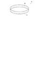
動き監視装置3は、センサー部10と、報知部30と、情報処理部20とを含んで構成されている。
センサー部10と、報知部30は、装着品60に取り付けられ、情報処理部20は、装着品60、被験者であるユーザーM3、ユーザーM3の近傍のいずれかに配置されている。なお、図9では、情報処理部20の配置例を示している。
装着品60は、頭部に装着する環状のヘアバンドの形状をしている。また、図示しないが馬蹄型をした、いわゆるカチューシャ(髪の毛を押さえる装身具)や、帯状の形状でもよい。
ユーザーM3は装着品60を頭部に着用し、センサー部10が、ユーザーM3の頭部の動きを検出することができる。The motion monitoring device 3 includes a
The
The wearing
The user M3 wears the wearing
動き監視装置3では、センサー部10に備えられた加速度検出部11によってユーザーM3の動きを検出し、検出された検出データを情報処理部20に送信する。そして、情報処理部20において、受信した検出データに基づいて、ユーザーM3の動きの有無を判定し、例えば、図示しないディスプレイ等に表示したり、報知部30に報知信号を送信したりする。これにより、情報処理部20は、ユーザーM3の動きを監視することができる。 In the movement monitoring device 3, the
本実施形態では、センサー部10(図2参照)の加速度検出部11は、ユーザーM3の動き、すなわち加速度を検出するセンサーである。本実施形態では、ユーザーM3の頭部の動きをセンサー部10で測定する。なお、加速度検出部11は、二軸(x軸、y軸)の加速度が検出可能なセンサーである。また、加速度検出部11は、三軸以上(複数軸)の加速度が検出可能なセンサーであってもよい。 In the present embodiment, the
情報処理部20(図3参照)の記憶部23は、ユーザーM3の動きを変位情報23aとして連続的に記憶している。そして、判定部24は、センサー部10から送信された最新の変位情報23a(13a)が、閾値の範囲内にあるかを判定する。すなわちユーザーM3の頭部の動きが閾値の範囲内にあるかを判定する。
本実施形態の閾値とは、最新の変位情報23aより以前に記憶部23に記憶された変位情報23aに、所定の許容を付加したものを示す。The
The threshold value in the present embodiment indicates a value obtained by adding a predetermined allowance to the
ここで、ユーザーM3の動きの有無を判定する例について説明する。
図9(a)に示すように、ユーザーM3が立位の姿勢で安定した状態である場合、つまり、変位情報23aが閾値の範囲内にあれば、判定部24は、ユーザーM3の動きが小さい(動きが無い)と判定する。また、図9(b)に示すように、ユーザーM3が片足を上げて、目を閉じた姿勢で安定しない状態である場合、つまり、変位情報23aが閾値の範囲外にあれば、判定部24は、ユーザーM3の動きが大きい(動きが有る)と判定する。
たとえば、ユーザーM3の動きが大きい場合は、ユーザーM3がふらついていると考えることができる。Here, an example of determining the presence or absence of the movement of the user M3 will be described.
As shown in FIG. 9A, when the user M3 is in a stable state in a standing posture, that is, when the
For example, when the movement of the user M3 is large, it can be considered that the user M3 is wobbling.
報知信号出力部25は、ユーザーM3の動きが大きいと判定した場合、つまり、ふらついているとき、通信部22を介して、報知部30に報知信号25aを送信する。
報知信号25aを報知部30に送信するタイミングは、たとえば、変位情報23aが閾値の範囲外に出た回数を記憶し、所定の回数に達したときや、所定の回数を超えたときに送信する。また、変位情報23aの移動量が著しく大きいときにも、報知信号25aを送信してもよい。The notification
The timing at which the
出力部26は、ユーザーM3の動きに基づいて、図示しないディスプレイ等に、文章や図を表示し、ユーザーM3、または他のユーザーにふらつきや、ふらつくまでの時間を知らせることができる。 Based on the movement of the user M3, the
報知部30(図5参照)の通信部32は、情報処理部20と送受信が可能な図示しない送信部、および受信部を備えている。通信部32は、情報処理部20から送信された報知信号25aを受信し、報知信号35aとする。 The
報知手段35は、報知信号35aに基づいて、ユーザーM3のふらつきを警告や刺激で報知することができる。図9の例では、ユーザーM3が着用している装着品60に報知部30が取り付けられ、報知部30に図示しない振動発生器を搭載し、ユーザーM3に振動による刺激で報知する報知手段35を備えている。
報知手段35は、たとえば、報知部30にスピーカーを搭載し音による警告で報知するものでもよい。報知部30は、スピーカーから、ふらつきの方向に対応して、音階の変更や、ふらつきの大小によって、音量の変更をした音を出力してもよい。また、ユーザーが意図して頭を動かし、音階と音量とを制御し、メロディーを奏でる楽器に用いてもよい。報知手段35は、報知部30の構成によって報知方法を適宜変更することができる。Based on the
For example, the
以上述べたように、第3実施形態にかかる動き監視装置3によれば、以下の効果を得ることができる。
第3実施形態によれば、動き監視装置3は、ユーザーM3が着用している装着品60にセンサー部10が取り付けられ、その装着品60の動きから変位情報13aを取り出す。そして、情報処理部20に変位情報13aを送信し、その変位情報23a(13a)が閾値の範囲内か否かによって動き(ふらつき)の有無を判定する。変位情報23aが閾値の範囲外であれば、ふらつきであると判定し、報知手段35でユーザーM3に注意を促すことができる。
また、動き監視装置3は、ふらつきを判定することができるために、バランスを維持するゲーム、平衡感覚を養うトレーニングに応用することができる。また、ふらつきの判定を数値化することで、ふらつきの症状がある疾病の診断や、飲酒検問(アルコール検査)で車両等の運転手の歩行検査時におけるふらつきの確認などに応用してもよい。As described above, according to the motion monitoring apparatus 3 according to the third embodiment, the following effects can be obtained.
According to the third embodiment, the motion monitoring device 3 has the
Further, since the motion monitoring device 3 can determine the wobble, it can be applied to a game for maintaining balance and a training for developing a sense of balance. Further, the determination of wandering may be converted into a numerical value, and may be applied to diagnosis of a disease having a wandering symptom or confirmation of wandering during a walking test of a driver of a vehicle or the like by a drinking check (alcohol test).
動き監視装置3は、小さく、かつ少ない構成部材で動き(ふらつき)を監視し、報知ができるため、小型化でき、可搬性があり利便性が向上する。 Since the motion monitoring device 3 can monitor and notify the motion (stagger) with a small and small number of constituent members, the motion monitoring device 3 can be miniaturized, has portability, and improves convenience.
(変形例)
図10は、変形例にかかる動き監視装置3aの構成例を示す斜視図である。動き監視装置3aは、センサー部10と、情報処理部20と、報知部30と、を備えて構成され、センサー部10と、報知部30は、装着品60に取り付けられている。なお、図10では、センサー部10、情報処理部20、報知部30の図示を省略している。
変形例では、報知部30に図示しない振動発生器を搭載し、ユーザーに振動による刺激で報知する報知手段35を備えている。図10で示すように、装着品60には、周方向に沿って、複数の報知手段35が一定の配置で設けられている。
ユーザーが装着品60を頭部に着用すると、センサー部10が検出したユーザーの頭の動きの方向と、同一方向となる位置に配置されている報知手段35を振動させることで、着用したユーザーに自身がふらついている方向を報知することができる。(Modification)
FIG. 10 is a perspective view illustrating a configuration example of the
In the modification, a vibration generator (not shown) is mounted on the
When the user wears the wearing
(加速度検出部)
上述した実施形態にかかる加速度検出部11(11a)について説明する。
図11(a)は、加速度検出部11(11a)の構成を示す平面図である。図11(b)は、加速度検出部11(11a)の構成を示す断面図であり、図11(a)におけるI−I線に沿う断面を表している。そして、図11では、互いに直交する3つの軸として、x軸、y軸、z軸を図示している。なお、説明の便宜上、平面図では、リッド202の図示を省略している。(Acceleration detector)
The acceleration detector 11 (11a) according to the above-described embodiment will be described.
Fig.11 (a) is a top view which shows the structure of the acceleration detection part 11 (11a). FIG.11 (b) is sectional drawing which shows the structure of the acceleration detection part 11 (11a), and represents the cross section along the II line | wire in Fig.11 (a). In FIG. 11, the x axis, the y axis, and the z axis are illustrated as three axes orthogonal to each other. For convenience of explanation, the
図11に示すように、加速度検出部11(11a)は、パッケージ200と、素子ベース体221および感圧素子220を有している物理量検出センサー218と、を備えている。
まず、パッケージ200は、パッケージベース201およびリッド202からなっている。パッケージベース201は、+z軸方向から見た平面視で四角形の形状をなす平板である。
このパッケージベース201は、物理量検出センサー218の素子ベース体221を固定するための段部203を有しており、それらは、y軸方向の一方の端部にx軸に沿って設けられている段部203aと、y軸方向の他方の端部における2つの角部近傍にそれぞれ設けられている段部203b,203cと、である。
また、パッケージベース201は、平板を貫通している孔、および孔を塞ぐための封止材からなる封止部204と、段部203a,203b,203cの設けられている面と反対側の面に形成され外部の発振回路等と接続するための外部端子207と、を有している。
このパッケージベース201は、セラミックグリーンシートを焼成した酸化アルミニウム焼結体で形成されている。セラミックの酸化アルミニウム焼結体は、パッケージ用として優れているが、加工が難しい材料である。しかし、この場合、パッケージベース201が平板状であるため、平板以外の形状に形成する場合と比べて、容易に形成することができる。なお、パッケージベース201は、水晶、ガラスおよびシリコン等の材料を用いて形成することもできる。As shown in FIG. 11, the acceleration detection unit 11 (11 a) includes a
First, the
The
Further, the
The
リッド202は、内部側に凹状に形成されている収容部206を有し、パッケージベース201の段部203a,203b,203cをガイドにして、感圧素子220を覆うように配置されパッケージベース201に固定される。
このリッド202は、パッケージベース201と同じ材料や、コバール、ステンレス鋼などの金属等を用いることができ、ここでは、収容部206の形成がセラミックより容易に行なえるコバールを用いている。そして、リッド202は、シームリング205を介してパッケージベース201に接合されると、収容部206を減圧された気密状態等に封止することができる。The
The
ここで、収容部206の封止は、パッケージベース201とリッド202との接合後、封止部204の孔から収容部206内の空気を抜いて減圧し、孔をロウ材(封止材)で塞ぐ方法で行われている。これにより、物理量検出センサー218は、減圧されて気密状態の収容部206内に封止される。なお、収容部206の内部は、窒素、ヘリウム、アルゴンなどの不活性ガスが充填されていてもよい。 Here, the
物理量検出センサー218は、パッケージベース201に固定される素子ベース体221と、素子ベース体221に固定され、たとえば、振動等の物理量を検出するための感圧素子220と、を有している。素子ベース体221は、水晶板からエッチング等で形成され、x,y平面に沿って位置する板状の形態である。この素子ベース体221は、平面視で略四角形のリング状である固定部(ベース部)211(211a〜211f)と、固定部211の内部側(リング状内)に配置されている可動部212(212a〜212c)と、固定部211と可動部212とを接続している継ぎ手部213と、を有している。 The physical
固定部211は、x軸およびy軸に沿ってリング状をなす枠部211aと、x軸に沿う一方の枠部211aの中央からy軸に沿って外部側に突出している素子載置部211bと、y軸に沿う一方の枠部211aから分岐し枠部211aの外周に沿って素子載置部211bの近傍まで延出している腕部211cと、y軸に沿う他方の枠部211aから分岐し枠部211aの外周に沿って素子載置部211bの近傍まで延出している腕部211dと、x軸に沿う他方の枠部211aの一端から分岐し枠部211aの外周に沿って腕部211dの分岐近傍まで延出している腕部211eと、x軸に沿う他方の枠部211aの他端から分岐し枠部211aの外周に沿って腕部211cの分岐近傍まで延出している腕部211fと、を有している。 The fixing portion 211 includes a
腕部211c,211d,211e,211fは、素子ベース体221をパッケージベース201に固定するための部位であり、腕部211cの先端部が支持部217(217a)(図11)を介して段部203aに固定され、腕部211dの先端部が支持部217(217b)を介して段部203aに固定され、腕部211eの先端部が支持部217(217c)を介して段部203bに固定され、腕部211fの先端部が支持部217(217d)を介して段部203cに固定されている。支持部217は、この場合、接着剤であって、腕部211c,211d,211e,211fを介して、固定部211の全体を所定の間隙を設けた状態で段部203に固定している。 The
可動部212(212a〜212c)は、枠部211aによって囲まれていて、素子載置部211bが形成されている枠部211aに継ぎ手部213を介して接続されている。つまり、可動部212は、継ぎ手部213によって枠部211aに片持ち支持された状態である。そして、可動部212は、継ぎ手部213と反対方向にy軸に沿って延出している素子載置部212aと、素子載置部212aの両側に設けられy軸に沿ってそれぞれ延出している質量体載置部212bと、を有している。なお、ここでは、可動部212における感圧素子220が載置される側の面を主面212cと称する。 The movable part 212 (212a to 212c) is surrounded by the
そして、可動部212の質量体載置部212bには、錘の役目をする質量体215が設けられている。質量体215(215a〜215d)は、一方の質量体載置部212bの主面212c側に設けられている質量体215aと、平面視で質量体215aと重なるように主面212cと反対側の面に設けられている質量体215cと、他方の質量体載置部212bの主面212c側に設けられている質量体215bと、平面視で質量体215bと重なるように主面212cと反対側の面に設けられている質量体215dと、を有している。これらの質量体215は、接合部216を介して可動部212に固定されていて、接合部216は、この場合、質量体215の重心位置に設けられている接着剤であって、質量体215と可動部212とを所定の間隙を空けた状態で固定している。 A mass body 215 serving as a weight is provided on the mass
また、感圧素子220は、固定部211の素子載置部211bに接着剤223で固定される基部221aと、可動部212の素子載置部212aに接着剤223で固定されている基部221bと、基部221aと基部221bとの間にあって物理量を検出するための振動梁部222(222a,222b)と、を有している。即ち、感圧素子220は、固定部(ベース部)211と可動部212とに接続し、継ぎ手部213を跨ぐように配置されている。この場合、振動梁部222は、その形状が角柱状であり、振動梁部222a,222bのそれぞれに設けられた励振電極(図示省略)に駆動信号(交流電圧)が印加されると、x軸に沿って、互いに離間、または近接するように屈曲振動をする。励振電極は、駆動信号の印加のために、図示しない配線によって外部端子207と電気的に接続されている。 The pressure-
この感圧素子220は、水晶の原石等から所定の角度で切り出された水晶基板を、フォトリソグラフィー技術およびエッチング技術によってパターニングすることにより形成されている。このように、感圧素子220を素子ベース体221と同質材料である水晶で形成すれば、感圧素子220と素子ベース体221との線膨張係数の差を小さくすることができて好ましい。これは、感圧素子220および素子ベース体221を水晶以外の材料で形成する場合にも当てはまることである。 The pressure-
次に、物理量検出センサー218の動作について説明する。図11(b)に示すように、物理量検出センサー218に、たとえば、+z方向(主面212cと交差する方向)に、振動等の物理量が印加されると、可動部212には−z方向に力が作用し、可動部212は継ぎ手部213を支点として−z方向に変位する。これにより、感圧素子220には、y軸に沿って基部221aと基部221bとが互いに離れる方向の力が加わり、感圧素子220の振動梁部222には引っ張り応力が生じる。そのため、振動梁部222の振動する周波数である共振周波数は、高くなる。 Next, the operation of the physical
一方、物理量検出センサー218に、たとえば、−z方向(主面212cと交差する方向)に、たとえば、振動等の物理量が印加されると、可動部212には+z方向に力が作用し、可動部212は、継ぎ手部213を支点として+z方向に変位する。これにより、感圧素子220には、y軸に沿って基部221aと基部221bとが互いに近づく方向の力が加わり、感圧素子220の振動梁部222には圧縮応力が生じる。そのため、振動梁部222の共振周波数は、低くなる。 On the other hand, when a physical quantity such as vibration is applied to the physical
1,2,3,3a…動き監視装置、10…センサー部、11,11a…加速度検出部、12,22,32…通信部、14…演算部、14a…フィルター回路、14b…積分回路、13,23,33…記憶部、13a,23a…変位情報、18,28,38…制御部、20…情報処理部、24…判定部、25…報知信号出力部、25a,35a…報知信号、26…出力部、30…報知部、35…報知手段、40,60…装着品、50…帽子、52…ハンドル、200…パッケージ、201…パッケージベース、202…リッド、203…段部、204…封止部、205…シームリング、206…収容部、207…外部端子、211…固定部、212…可動部、213…継ぎ手部、215…質量体、216…接合部、217…支持部、218…物理量検出センサー、220…感圧素子、221…素子ベース体、222…振動梁部、S1…閾値、M1,M2,M3…ユーザー。 DESCRIPTION OF
Claims (5)
Translated fromJapanese前記検出データを用いて変位情報を演算する演算部と、
前記変位情報に基づいて動きの有無を判定する判定部と、
前記判定に基づき、報知信号を前記報知部に送信する報知信号出力部と、
受信した前記報知信号に基づいて被験者に報知する報知手段と、を備える
ことを特徴とする動き監視装置。An acceleration detector that detects acceleration and outputs detection data;
A calculation unit for calculating displacement information using the detection data;
A determination unit that determines the presence or absence of movement based on the displacement information;
Based on the determination, a notification signal output unit that transmits a notification signal to the notification unit;
A motion monitoring device comprising: a notification unit configured to notify a subject based on the received notification signal.
Priority Applications (2)
| Application Number | Priority Date | Filing Date | Title |
|---|---|---|---|
| JP2013223007AJP2015084787A (en) | 2013-10-28 | 2013-10-28 | Movement monitoring device |
| US14/506,947US20150116120A1 (en) | 2013-10-28 | 2014-10-06 | Motion monitoring device |
Applications Claiming Priority (1)
| Application Number | Priority Date | Filing Date | Title |
|---|---|---|---|
| JP2013223007AJP2015084787A (en) | 2013-10-28 | 2013-10-28 | Movement monitoring device |
Publications (1)
| Publication Number | Publication Date |
|---|---|
| JP2015084787Atrue JP2015084787A (en) | 2015-05-07 |
Family
ID=52994769
Family Applications (1)
| Application Number | Title | Priority Date | Filing Date |
|---|---|---|---|
| JP2013223007APendingJP2015084787A (en) | 2013-10-28 | 2013-10-28 | Movement monitoring device |
Country Status (2)
| Country | Link |
|---|---|
| US (1) | US20150116120A1 (en) |
| JP (1) | JP2015084787A (en) |
Cited By (3)
| Publication number | Priority date | Publication date | Assignee | Title |
|---|---|---|---|---|
| JP2017185076A (en)* | 2016-04-07 | 2017-10-12 | 株式会社ジンズ | Information processing method, information processing device, and program |
| JP2017185072A (en)* | 2016-04-07 | 2017-10-12 | 株式会社ジンズ | Information processing method, information processing apparatus, and program |
| JP2022116232A (en)* | 2019-04-25 | 2022-08-09 | カシオ計算機株式会社 | Exercise support device, exercise support method, and exercise support program |
Families Citing this family (1)
| Publication number | Priority date | Publication date | Assignee | Title |
|---|---|---|---|---|
| US12329533B2 (en) | 2020-08-07 | 2025-06-17 | Dumisani Mlungwana | Balance test device and system for a modern functional reach test kit |
Family Cites Families (9)
| Publication number | Priority date | Publication date | Assignee | Title |
|---|---|---|---|---|
| US6790178B1 (en)* | 1999-09-24 | 2004-09-14 | Healthetech, Inc. | Physiological monitor and associated computation, display and communication unit |
| US5919149A (en)* | 1996-03-19 | 1999-07-06 | Allum; John H. | Method and apparatus for angular position and velocity based determination of body sway for the diagnosis and rehabilitation of balance and gait disorders |
| US20060251334A1 (en)* | 2003-05-22 | 2006-11-09 | Toshihiko Oba | Balance function diagnostic system and method |
| US8059000B2 (en)* | 2005-05-24 | 2011-11-15 | The Invention Science Fund I, Llc | Wearable/portable protection for a body |
| WO2010126878A1 (en)* | 2009-04-27 | 2010-11-04 | Mayo Foundation For Medical Education And Research | Fall detection |
| US8956293B2 (en)* | 2009-05-20 | 2015-02-17 | Sotera Wireless, Inc. | Graphical ‘mapping system’ for continuously monitoring a patient's vital signs, motion, and location |
| US8738323B2 (en)* | 2010-09-30 | 2014-05-27 | Fitbit, Inc. | Methods and systems for metrics analysis and interactive rendering, including events having combined activity and location information |
| US8473253B2 (en)* | 2010-10-21 | 2013-06-25 | Siemens Medical Solutions Usa, Inc. | Digital event timing |
| US10172555B2 (en)* | 2013-03-08 | 2019-01-08 | The Board Of Trustees Of The Leland Stanford Junior University | Device for detecting on-body impacts |
- 2013
- 2013-10-28JPJP2013223007Apatent/JP2015084787A/enactivePending
- 2014
- 2014-10-06USUS14/506,947patent/US20150116120A1/ennot_activeAbandoned
Cited By (4)
| Publication number | Priority date | Publication date | Assignee | Title |
|---|---|---|---|---|
| JP2017185076A (en)* | 2016-04-07 | 2017-10-12 | 株式会社ジンズ | Information processing method, information processing device, and program |
| JP2017185072A (en)* | 2016-04-07 | 2017-10-12 | 株式会社ジンズ | Information processing method, information processing apparatus, and program |
| JP2022116232A (en)* | 2019-04-25 | 2022-08-09 | カシオ計算機株式会社 | Exercise support device, exercise support method, and exercise support program |
| US11925851B2 (en) | 2019-04-25 | 2024-03-12 | Casio Computer Co., Ltd. | Exercise assisting device, exercise assisting method, and storage medium |
Also Published As
| Publication number | Publication date |
|---|---|
| US20150116120A1 (en) | 2015-04-30 |
Similar Documents
| Publication | Publication Date | Title |
|---|---|---|
| JP5838676B2 (en) | Arm-mounted electronic device and control method thereof | |
| JP2015084787A (en) | Movement monitoring device | |
| JP2008059459A (en) | Vehicle alert system | |
| JP2007319675A (en) | Exercise information determination method and wristwatch type device | |
| JP6266270B2 (en) | Exercise form analysis apparatus and exercise form analysis method | |
| JP2010246741A (en) | Biological posture monitoring system and control method of biological posture monitoring system | |
| WO2019054254A1 (en) | Display control device and program | |
| JP2005124914A (en) | Impedance measuring device and health care guideline advice apparatus | |
| JP6293543B2 (en) | Mobile terminal and sound notification method | |
| JP2008026075A (en) | Navigation system for motorcycle | |
| JP2009301457A (en) | Rescue system, transmitting device and communication device | |
| KR101433677B1 (en) | Membrane tension measuring apparatus | |
| JP5927843B2 (en) | Congestion determination device, pulse wave measurement device, and congestion determination method | |
| KR20080057651A (en) | Sound Recognition Assistance System and Sound Recognition Method for the Deaf | |
| US12109479B2 (en) | Exercise assistance device, exercise assistance method, and storage medium | |
| JP5603624B2 (en) | Information display device | |
| JP4539514B2 (en) | Hazardous location information collection system and in-vehicle equipment | |
| KR200457749Y1 (en) | Posture failure alarm device using gyro sensor | |
| JP2018074551A (en) | Bone conduction microphone, bone conduction microphone set and helmet | |
| KR20230120714A (en) | Smart pendant | |
| JP2016150179A (en) | Motion measuring device | |
| WO2019124068A1 (en) | Information processing device and method, and program | |
| JP2010197234A (en) | Directional guidance system without visual sense | |
| JP7119616B2 (en) | Exercise support device, exercise support method and exercise support program | |
| JP2016150178A (en) | Motion measuring device |
Legal Events
| Date | Code | Title | Description |
|---|---|---|---|
| RD04 | Notification of resignation of power of attorney | Free format text:JAPANESE INTERMEDIATE CODE: A7424 Effective date:20160610 | |
| RD03 | Notification of appointment of power of attorney | Free format text:JAPANESE INTERMEDIATE CODE: A7423 Effective date:20160624 |