JP2015084176A - Fault diagnostic apparatus and active machine - Google Patents
Fault diagnostic apparatus and active machineDownload PDFInfo
- Publication number
- JP2015084176A JP2015084176AJP2013222598AJP2013222598AJP2015084176AJP 2015084176 AJP2015084176 AJP 2015084176AJP 2013222598 AJP2013222598 AJP 2013222598AJP 2013222598 AJP2013222598 AJP 2013222598AJP 2015084176 AJP2015084176 AJP 2015084176A
- Authority
- JP
- Japan
- Prior art keywords
- abnormality determination
- unit
- abnormality
- criterion
- machine
- Prior art date
- Legal status (The legal status is an assumption and is not a legal conclusion. Google has not performed a legal analysis and makes no representation as to the accuracy of the status listed.)
- Pending
Links
- 230000005856abnormalityEffects0.000claimsabstractdescription346
- 238000012423maintenanceMethods0.000claimsabstractdescription122
- 238000003745diagnosisMethods0.000claimsdescription98
- 230000004044responseEffects0.000claimsdescription19
- 238000012937correctionMethods0.000claimsdescription15
- 238000012795verificationMethods0.000claims1
- 230000008859changeEffects0.000abstractdescription18
- 230000002159abnormal effectEffects0.000abstractdescription14
- 238000000034methodMethods0.000description13
- 230000008569processEffects0.000description10
- 238000010586diagramMethods0.000description9
- 230000008439repair processEffects0.000description9
- 238000004891communicationMethods0.000description6
- 230000000875corresponding effectEffects0.000description6
- 230000006870functionEffects0.000description6
- 230000000737periodic effectEffects0.000description6
- 238000012544monitoring processMethods0.000description5
- 238000005516engineering processMethods0.000description4
- 238000012360testing methodMethods0.000description4
- 230000000694effectsEffects0.000description3
- 238000013480data collectionMethods0.000description2
- 230000006866deteriorationEffects0.000description2
- 230000006872improvementEffects0.000description2
- 238000007689inspectionMethods0.000description2
- 238000005065miningMethods0.000description2
- 238000012545processingMethods0.000description2
- 230000009467reductionEffects0.000description2
- 230000001133accelerationEffects0.000description1
- 238000004364calculation methodMethods0.000description1
- 230000015556catabolic processEffects0.000description1
- 238000010276constructionMethods0.000description1
- 238000007796conventional methodMethods0.000description1
- 230000002596correlated effectEffects0.000description1
- 238000013461designMethods0.000description1
- 238000001514detection methodMethods0.000description1
- 230000036541healthEffects0.000description1
- 230000007246mechanismEffects0.000description1
- 238000000491multivariate analysisMethods0.000description1
- 230000003449preventive effectEffects0.000description1
- 230000009466transformationEffects0.000description1
Images


Landscapes
- Testing And Monitoring For Control Systems (AREA)
Abstract
Description
Translated fromJapanese本発明は、稼働機械の保守管理技術に関する故障診断装置および稼働機械に関する。 The present invention relates to a failure diagnosis apparatus relating to maintenance management technology for operating machines and operating machines.
ガスタービンなどを用いた各種プラントや設備において、その異常を早期に発見して原因を診断し、対策を行うことは、社会へのダメージを最小限に抑えるために極めて重用である。
また、ガスタービンや蒸気タービンのみならず、航空機や重機のエンジン等でも、搭載部品の劣化・寿命などを早期に異常を発見して診断しなければならない装置,設備は枚挙に暇がない。In various plants and equipment using gas turbines, it is extremely important to detect the abnormality early and diagnose the cause and take measures to minimize damage to society.
Moreover, not only gas turbines and steam turbines, but also aircraft and heavy machinery engines, etc., there is no spare time for equipment and facilities that must detect and diagnose abnormalities in the deterioration and life of mounted parts at an early stage.
このような異常を発見して診断する技術として、作業履歴や交換部品情報などの過去の事例からなる保守履歴情報を、キーワードベースで相互に関連付けておき、設備に付加した多次元センサの出力信号を対象とした異常検知に基づき、異常を検知し、検知した異常と関連付けられた保守履歴情報とを結びつけることにより、発生した異常に対しなすべき診断・処置を明らかにする技術がある(特許文献1参照)。 As a technology for discovering and diagnosing such anomalies, maintenance history information consisting of past cases such as work history and replacement parts information is correlated with each other on a keyword basis, and output signals of multidimensional sensors added to equipment There is a technology that clarifies diagnosis and treatment to be performed for an abnormality that has occurred by detecting the abnormality and linking the detected abnormality to the maintenance history information associated with the abnormality (Patent Document) 1).
搭載部品の劣化・寿命などを早期に異常を発見して診断しなければならない装置,設備の例として、建設機械を始めとする産業用の稼働機械(作業機械)がある。とりわけ、鉱山などで使用されるショベルやダンプなどの作業用の稼働機械は、24時間稼動することが前提である。このため、故障などによって停止した場合に影響が大きく、保守によって機器を最適な状態に保つ予防保全の措置が取られることが多い。
保守は主として稼働時間を基準にした定期保守が一般的で、設計基準で定められた各部品の点検や整備・交換が機械の稼働時間に応じて行われる。Examples of devices and equipment that must detect and diagnose abnormalities of deterioration and life of mounted parts at an early stage include industrial machines (work machines) such as construction machines. In particular, working machines such as excavators and dumpers used in mines are premised on operating for 24 hours. For this reason, there is a great influence when the operation is stopped due to a failure or the like, and preventive maintenance measures are often taken to maintain the equipment in an optimum state by maintenance.
The maintenance is generally regular maintenance based on the operation time, and inspection, maintenance, and replacement of each part determined by the design standard is performed according to the operation time of the machine.
近年では、このような定期保守に加えて、稼動機械に備えられたセンサデータを収集し、収集したセンサデータを監視することによって稼動機械の状態異常を早期に発見し、故障停止前に保守を行うCBM(Condition Based Maintenance:状態基準保守)が運用されるようになってきている。
このようなCBMによって、定期保守の合間に発生する突発的な故障停止を防止して、機械の故障停止による影響を最小限にとどめることが実施されている。In recent years, in addition to such regular maintenance, the sensor data provided in the operating machine is collected, and the collected sensor data is monitored to detect an abnormal state of the operating machine at an early stage. CBM (Condition Based Maintenance) is being operated.
With such a CBM, sudden failure stoppages that occur between regular maintenances are prevented, and the effects of machine failure stoppages are minimized.
ここで、上述のようなCBMを実現するためには、稼動機械の状態を監視する監視システムが活用される。近年ではAHM(Asset Health Monitoring、あるいはAsset Health Management)システムと呼ばれる鉱山における稼動機械の保守管理システムが活用される傾向にあり、AHMシステムによって機械の保守管理を効率化できるようになってきている。 Here, in order to realize the CBM as described above, a monitoring system for monitoring the state of the working machine is utilized. In recent years, a maintenance management system for an operating machine in a mine called an AHM (Asset Health Monitoring) system has been used, and the maintenance management of the machine can be made more efficient by the AHM system.
このような機械の状態を監視するシステムにおいては、上述のように稼動機械のセンサデータからAHMシステムが出力する機械状態の正常・異常を通知するアラームの精度が重要になる。 In such a system for monitoring the state of the machine, as described above, the accuracy of the alarm for notifying normality / abnormality of the machine state output from the AHM system from the sensor data of the operating machine is important.
しかし、このアラームを通知するかどうかの基準となる異常判定基準は、稼働機械における特有の問題を有しているため、基準の精度を十分に確保することが難しいとの問題があった。
その原因の一つとして、例えば、部品1つ1つが、ロット数が少なく、また高額であるため、様々な条件を模擬した故障試験を行うことが困難であり、そのために基準値は理論値に安全係数を乗じる、加速試験における摩耗結果から見積もる等の手法によって異常判定基準を決定していた、との事情がある。However, since the abnormality determination standard that is a criterion for notifying the alarm has a problem specific to the working machine, there is a problem that it is difficult to sufficiently ensure the accuracy of the standard.
One reason for this is that, for example, each part has a small number of lots and is expensive, so it is difficult to perform a failure test that simulates various conditions. There is a situation that the abnormality criterion was determined by a method such as multiplying by a safety factor or estimating from a wear result in an acceleration test.
このような様々な問題のために異常判定基準の精度を確保することが難しく、異常を知らせるアラームの精度が高くない、との問題を有していた。 Due to such various problems, it is difficult to ensure the accuracy of the abnormality determination standard, and there is a problem that the accuracy of the alarm for notifying the abnormality is not high.
ここで、特許文献1等の従来の技術では、異常判定基準が正しいことが前提となっている。このため、特許文献1等の従来の技術では、精度が高くない異常判定基準を用いて異常の有無を判定しているため、機械が正常であるのに異常であると出力(誤報)したり、逆に機械が異常であるのに正常であると出力(失報)したり、との状態を解消することが難しく、適切な保守に寄与できないといった状況が生じる。 Here, in the conventional technology such as Patent Document 1, it is assumed that the abnormality determination standard is correct. For this reason, in the conventional techniques such as Patent Document 1, since the presence / absence of an abnormality is determined using an abnormality determination criterion that is not highly accurate, an output (false report) is output when the machine is normal but abnormal. Conversely, when the machine is abnormal, it is difficult to output (missing information) or to cancel the state, and cannot contribute to appropriate maintenance.
このような問題に対し、機械の状態監視の専門家などがアラームの判定精度に関係する設定変更を実施することが考えられる。
しかし、実際には、様々なセンサデータを参照しながら個別の機械ごとの調整を実施することは非常に難しいとの実状がある。For such a problem, it is conceivable that a machine condition monitoring expert or the like performs a setting change related to the alarm determination accuracy.
However, in practice, it is very difficult to perform adjustment for each individual machine while referring to various sensor data.
本発明は、稼働機械の部品の異常の有無を判定する故障診断装置であって、特に実際の稼働状態を反映させた異常判定基準の設定が困難な稼働機械に好適な、機械状態の正常・異常の判定の精度を向上させることに寄与する故障診断装置とそれを備えた稼働機械を提供する。 The present invention is a failure diagnosis device that determines whether there is an abnormality in a part of an operating machine, and is particularly suitable for an operating machine in which it is difficult to set an abnormality determination standard that reflects an actual operating state. Provided is a failure diagnosis device that contributes to improving the accuracy of abnormality determination and an operating machine including the failure diagnosis device.
上記目的を達成するために、第1の発明は、稼働機械に搭載され、この稼働機械の各部品の稼働状態を検知するためのセンシング部と、このセンシング部から受け取った少なくとも1つのセンサデータと異常判定基準とに基づいて前記各部品の稼働状態における異常の有無を判定する異常判定部と、前記異常判定結果が適切であるか否かを判定し、この判定結果から新規の異常判定基準を求める異常判定結果照合部と、前記異常判定部が異常の有無を判定する際に用いた現行の異常判定基準、前記異常判定結果照合部によって求められた新規の異常判定基準を表示装置に出力するための出力部と、前記異常判定部が判定に用いる異常判定基準を更新する異常判定基準修正部とを備えたことを特徴とする。 In order to achieve the above object, a first aspect of the present invention is a sensing unit mounted on an operating machine for detecting an operating state of each part of the operating machine, and at least one sensor data received from the sensing unit. An abnormality determination unit that determines whether or not there is an abnormality in the operating state of each component based on the abnormality determination criterion, and determines whether or not the abnormality determination result is appropriate, and a new abnormality determination criterion is determined from this determination result. The abnormality determination result collation unit to be obtained, the current abnormality determination standard used when the abnormality determination unit determines whether or not there is an abnormality, and the new abnormality determination standard obtained by the abnormality determination result collation unit are output to the display device. And an abnormality determination standard correction unit that updates an abnormality determination standard used for determination by the abnormality determination unit.
これにより、非常に高度な判断を要求される異常判定基準の変更のための判断材料の提供が可能となり、異常判定基準の更新を安全かつ正確に実施することができるようになり、アラームの精度向上に大きく寄与することができる。 As a result, it is possible to provide judgment materials for changing abnormal judgment criteria that require extremely advanced judgments, and it is possible to update the abnormality judgment criteria safely and accurately. This can greatly contribute to improvement.
また、第2の発明は、上記第1の発明において、前記異常判定結果照合部は、前記異常判定部によって判定された異常判定結果と前記稼働機械の稼働状態を維持するために実施された保守作業履歴とを用いて前記異常判定結果が適切であるか否かを判定することを特徴とする。 In addition, in a second aspect based on the first aspect, the abnormality determination result matching unit is a maintenance performed to maintain the abnormality determination result determined by the abnormality determination unit and the operating state of the operating machine. It is characterized by determining whether or not the abnormality determination result is appropriate using a work history.
これにより、異常判定結果が適切であるか否かの判定精度をより向上させることができる。 Thereby, the determination accuracy of whether or not the abnormality determination result is appropriate can be further improved.
また、第3の発明は、上記第1の発明において、前記異常判定基準修正部は、前記出力部によって前記表示装置に表示された前記現行の異常判定基準と前記新規の異常判定基準とのいずれかが前記異常判定部で用いる異常判定基準に適しているか、の入力信号をうけて、前記異常判定部が判定に用いる異常判定基準を更新することを特徴とする。 According to a third aspect of the present invention, in the first aspect, the abnormality determination reference correction unit is any of the current abnormality determination criterion and the new abnormality determination criterion displayed on the display device by the output unit. In response to an input signal indicating whether the abnormality determination unit is suitable for the abnormality determination criterion used in the abnormality determination unit, the abnormality determination criterion used in the determination by the abnormality determination unit is updated.
これにより、ディスパッチャ等による、現行の異常判定基準と新規の異常判定基準とのどちらが基準として適しているかの判断の入力を受けた上での異常判定基準の更新を実施することがより確実に実施することができる。 As a result, it is more reliable to update the abnormality judgment criteria after receiving an input from the dispatcher etc. to determine which of the current abnormality judgment criteria and the new abnormality judgment criteria is appropriate. can do.
また、第4の発明は、上記第3の発明において、前記出力部によって前記表示装置に表示された前記現行の異常判定基準と前記新規の異常判定基準とのいずれかが前記異常判定部で用いる異常判定基準に適しているか、を入力するための入力部を更に備え、前記異常判定基準修正部は、前記入力部からの入力信号をうけて、前記異常判定部が判定に用いる異常判定基準を更新することを特徴とする。 According to a fourth aspect of the present invention, in the third aspect of the present invention, the abnormality determination unit uses either the current abnormality determination criterion or the new abnormality determination criterion displayed on the display device by the output unit. It further includes an input unit for inputting whether it is suitable for an abnormality determination criterion, and the abnormality determination criterion correction unit receives an input signal from the input unit, and an abnormality determination criterion used by the abnormality determination unit for determination. It is characterized by updating.
これにより、ディスパッチャ等による、現行の異常判定基準と新規の異常判定基準とのどちらが適しているかの判断の入力を受けた上での異常判定基準の更新を実施することが更に確実に実施することができる。 As a result, it is possible to more reliably implement an update of the abnormality determination criteria after receiving an input on whether a current abnormality determination criterion or a new abnormality determination criterion is suitable by a dispatcher or the like. Can do.
また、第5の発明は、上記第1の発明において、前記異常判定結果照合部は、前記異常判定結果が適切でないと判定されたときは、予め設定されたリードタイムを用いて新規の異常判定基準を求めることを特徴とする。 According to a fifth aspect of the present invention, in the first aspect, when the abnormality determination result collating unit determines that the abnormality determination result is not appropriate, a new abnormality determination is performed using a preset lead time. It is characterized by obtaining a reference.
これにより、新規の異常判定基準の精度をより高いものとすることができる。 Thereby, the accuracy of the new abnormality determination standard can be made higher.
また、第6の発明は、上記第1の発明において、前記出力部は、前記現行の異常判定基準、前記新規の異常判定基準に加え、更に、前記異常判定部が出力する異常判定結果と、前記稼働機械の稼働状態を維持するために実施された保守作業履歴とを前記表示装置に出力することを特徴とする。 Further, in a sixth aspect based on the first aspect, in addition to the current abnormality determination standard and the new abnormality determination standard, the output unit further includes an abnormality determination result output by the abnormality determination unit, The maintenance work history performed to maintain the operating state of the operating machine is output to the display device.
これにより、現行の異常判定基準と新規の異常判定基準とのいずれかが基準にふさわしいかの判断材料をより多く提供することができる。 As a result, it is possible to provide more judgment materials as to whether one of the current abnormality judgment standard and the new abnormality judgment standard is appropriate.
また、第7の発明は、上記第1乃至第6の発明のいずれかの故障診断装置を備えたことを特徴とする稼働機械である。 According to a seventh aspect of the present invention, there is provided an operating machine comprising the failure diagnosis apparatus according to any one of the first to sixth aspects.
これにより、故障診断装置自体を稼働機械が備えているため、管理事務所などが設けられていない場合や通信状況が悪い場合であっても、稼働機械に対する故障診断の精度の向上を図ることができる。 As a result, since the operating machine is equipped with the failure diagnosis device itself, it is possible to improve the accuracy of the failure diagnosis for the operating machine even when there is no management office or the communication situation is bad. it can.
本発明によれば、稼働機械の保守管理システムにおけるアラームの精度を調整するための仕組みを備えたことにより、機械状態の正常・異常を通知するアラームの精度を向上させることに大きく寄与することができるようになる。よって実際の稼働状態を反映させた異常判定基準の設定が困難な稼働機械に好適な、機械状態の正常・異常の判定の精度を向上させることに寄与する故障診断装置とそれを備えた稼働機械を提供することが可能となる。 According to the present invention, by providing a mechanism for adjusting the accuracy of the alarm in the maintenance management system of the operating machine, it can greatly contribute to improving the accuracy of the alarm for notifying normality / abnormality of the machine state. become able to. Therefore, it is suitable for working machines where it is difficult to set an abnormality judgment standard that reflects actual working conditions, and contributes to improving the accuracy of machine state normality / abnormality diagnosis and working machines equipped with the same Can be provided.
以下に本発明の故障診断装置および稼働機械の一実施形態を、図面を参照しつつ説明する。
図1は本発明の故障診断装置の実施形態を備えた鉱山の操業の様子を示した斜視図、図2は本発明の故障診断装置の実施形態を備えた鉱山で稼働する稼働機械の概略側面図、図3は本発明の故障診断装置の実施形態を備えた鉱山におけるデータ収集の流れの機能的構成を表すブロック図、図4は本発明の故障診断装置の実施形態の構成と情報の流れを表す概略図、図5は本発明の故障診断装置の実施形態の機能的構成を表すブロック図、図6は本発明の故障診断装置の実施形態における故障診断のフローチャート図、図7は本発明の故障診断装置の実施形態におけるセンサデータのタイムチャートの一例を示す図、図8は本発明の故障診断装置の実施形態における、アラーム履歴の一例を示す図、図9,11,13,15,17は本発明の故障診断装置の実施形態におけるセンサデータのタイムチャートの他の一例を示す図、図10,12,14,16,18は本発明の故障診断装置の実施形態における、アラーム履歴の他の一例を示す図、図19は本発明の故障診断装置の実施形態の異常判定結果照合部における新規の判定基準の演算のフローチャート図の一例を示す図、図20は本発明の故障診断装置の実施形態における、表示装置に表示される現行の判定基準と新規の判定基準とを比較表示する画面の一例を示す図、図21は本発明の故障診断装置を備えた稼働機械の一例を示す図である。Hereinafter, an embodiment of a failure diagnosis apparatus and an operating machine according to the present invention will be described with reference to the drawings.
FIG. 1 is a perspective view showing a state of operation of a mine equipped with an embodiment of the failure diagnosis apparatus of the present invention, and FIG. 2 is a schematic side view of an operating machine operating in the mine equipped with an embodiment of the failure diagnosis apparatus of the present invention. FIG. 3, FIG. 3 is a block diagram showing the functional configuration of the flow of data collection in a mine equipped with an embodiment of the fault diagnosis apparatus of the present invention, and FIG. 4 is the configuration and information flow of the embodiment of the fault diagnosis apparatus of the present invention. FIG. 5 is a block diagram showing the functional configuration of the embodiment of the failure diagnosis apparatus of the present invention, FIG. 6 is a flowchart of failure diagnosis in the embodiment of the failure diagnosis apparatus of the present invention, and FIG. 7 is the present invention. FIG. 8 is a diagram showing an example of a time chart of sensor data in the embodiment of the fault diagnosis apparatus of FIG. 8, FIG. 8 is a diagram showing an example of alarm history in the embodiment of the fault diagnosis apparatus of the present invention, and FIGS. 17 is because of the present invention The figure which shows another example of the time chart of the sensor data in embodiment of a diagnostic apparatus, FIG.10,12,14,16,18 is a figure which shows another example of the alarm history in embodiment of the failure diagnostic apparatus of this invention. FIG. 19 is a diagram illustrating an example of a flowchart for calculating a new determination criterion in the abnormality determination result matching unit of the embodiment of the failure diagnosis apparatus of the present invention. FIG. 20 is a display in the embodiment of the failure diagnosis apparatus of the present invention. FIG. 21 is a diagram showing an example of a screen for comparing and displaying a current judgment criterion and a new judgment criterion displayed on the apparatus, and FIG. 21 is a diagram showing an example of an operating machine provided with the failure diagnosis apparatus of the present invention.
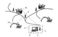
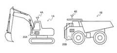
図1乃至図3において、鉱山の採石場では、ショベル1Aやダンプ1B等の稼働機械(作業機械)1が使用されおり、それら稼働機械1を管理する運行管理システムが用いられている。この運行管理システムでは、採石場の近傍若しくは遠隔の管理事務所2に、機械管理装置3が設置されている。
稼働機械1A,1Bには、GPS衛星を利用して自機の位置を取得する位置取得装置(図示せず)と、稼働機械1の部品の稼働状況を検知するための各種センサ30(301,302,303,…3nn)が備えられている。そして、各稼働機械1の稼働情報(詳細には、位置,稼働時間,各種センサ30の取得したセンサデータに関する情報など)や機体情報(詳細には、機種および号機に関する情報など)が稼働機械1に搭載された車載コントローラ20(20A,20B)の記憶装置202に蓄積される。この蓄積された情報は稼働機械1に搭載された演算装置201によって演算処理され、無線通信システム4,4A,4B(詳細には、例えば、稼働機械1側の無線通信装置4A,4B、中継局4、および管理事務所2側の無線通信装置など)を介して機械管理装置3に送信されるようになっている。1 to 3, an operating machine (working machine) 1 such as an excavator 1 </ b> A or a dumper 1 </ b> B is used in a mine quarry, and an operation management system that manages these operating machines 1 is used. In this operation management system, a
The
図4に示すように、鉱山では、運転員7が稼動機械1を操作し、その稼動情報が機械管理装置3に蓄積される。機械管理装置3は各稼働機械1から収集した情報を示す表示装置9を有しており、この表示装置9に表示された管理画面をディスパッチャ6(管理者)が監視する。ディスパッチャ6は表示装置9の管理画面で示された情報から判断して運転員7に稼動機械1の操作に関する指示を与えるとともに、機械管理装置3に蓄積される稼動機械1の運行状態に基づいて保守員8に保守作業に関する指示を与える。 As shown in FIG. 4, in the mine, the
機械管理装置3では、稼動機械1の運行状態のうち、機械状態の健全性を判定するための機械状態診断部5が動作しており、稼動機械1が故障あるいは異常の兆候を示すと、機械状態診断部5において、各種センサ30が収集したセンサデータに基づいてその兆候を検知し、アラームとしてディスパッチャ6や保守員8に通知する。保守員8はアラームを確認すると、センサデータを参照したり、実際に機械の様子を確認したりすることで、アラームに対応する保守作業を実施するかを判断する。 In the
この機械状態診断部5は、図5に示すように、異常判定部53、異常判定結果照合部56、異常判定基準修正部57、入力部58、出力部59、記憶部50とを概略備えている。
この機械状態診断部5は、各稼働機械1から収集した各種センサ30のデータから稼働機械の稼働する部品に異常が発生したか否かを診断するとともに、異常判定結果52や保守作業履歴55を表示装置9の管理画面に表示するようになっている。なお、異常が発生したと判定された場合に異常判定結果52や保守作業履歴55を表示装置9の管理画面に表示してもよい。
また、機械状態診断部5は、異常判定基準52が必ずしも適切に設定されていない場合であっても、異常判定基準52の精度を高め保守を適切に実施することを可能とするために、現行の異常判定基準52A(図20参照)、新規の異常判定基準52B(図20参照)とを表示装置9の管理画面に表示して、ディスパッチャ6や保守員8に、異常判定基準52を現行の異常判定基準52Aから新規の異常判定基準52Bに変更するか、それとも現行の異常判定基準52Aのままとするのか、を判断するための情報を提供するよう構成されている。
ディスパッチャ6や保守員8は、管理画面に表示された現行の異常判定基準52Aおよび新規の異常判定基準52Bとを比較検討し、異常判定基準52を変更したほうが良いと判断したときは、機械状態診断部5の入力部58を用いて異常判定基準52の変更を指示する。これに対し、ディスパッチャ6や保守員8は、異常判定基準52を変更しないほうが良いと判断したときは、異常判定基準52の変更は行わない旨の指示を行う。この機能については詳しくは後述する。As shown in FIG. 5, the machine
The machine
In addition, the machine
When the dispatcher 6 or the maintenance staff 8 compares the current abnormality determination standard 52A and the new abnormality determination standard 52B displayed on the management screen and determines that the abnormality determination standard 52 should be changed, the machine state The change of the abnormality determination standard 52 is instructed using the
機械状態診断部5の入力部58は、ディスパッチャ6や保守員8が、出力部59によって表示装置9に表示された現行の異常判定基準52Aと新規の異常判定基準52Bとのいずれかが異常判定部53で用いる異常判定基準52に適しているか、を入力するための機器である。例えば、キーボードやマウス等のユーザーインターフェースである。 The
出力部59は、後述する異常判定部53が異常の有無を判定する際に用いた現行の異常判定基準52Aと、異常判定結果照合部56によって求められた新規の異常判定基準52Bとを表示装置9に出力するための出力端子である。
また、出力部59では、現行の異常判定基準52Aや新規の異常判定基準52Bに加え、更に、異常判定部53が出力する異常判定結果54と、稼働機械の稼働状態を維持するために実施された保守作業履歴55とを表示装置9に出力する。The
Further, in the
異常判定部53は、各種センサ30から受け取った少なくとも1つのセンサデータ51と異常判定基準52とに基づいて、稼働機械1A,1Bの各部品の稼働状態における異常の有無を判定する。 The
異常判定結果照合部56は、異常判定部53によって判定された異常判定結果54と稼働機械の稼働状態を維持するために実施された保守作業履歴55とを用いて、異常判定結果54が適切であるか否かを判定する。
また、異常判定結果照合部56は、異常判定結果54が適切でないと判定されたときは、予め設定されたリードタイムを用いて新規の異常判定基準52Bを求め、この求めた新規の異常判定基準52Bおよび現行の異常判定基準52Aとを表示装置9の管理画面に表示させるために、表示装置9に出力部59を介して出力する。
この異常判定結果照合部56において、新規の異常判定基準52Bを求めるために用いるリードタイムはアラームによる通知から、実際の保守作業を完了するまでの猶予時間を規定したもので、保守作業の内容によって基準が設定されている。そして、このリードタイムはあらかじめ異常判定結果照合部56に設定されているものであり、必要があれば、このリードタイムそのものがこの保守作業の基準に従って変更できるようになっている。The abnormality determination
Further, when it is determined that the
In this abnormality determination
異常判定基準修正部57は、ディスパッチャ6や保守員8が入力部58を操作することで入力した、出力部59によって表示装置9に表示された現行の異常判定基準52Aと新規の異常判定基準52Bとのいずれかが異常判定部53で用いる異常判定基準52に適しているかの入力信号をうけて、異常判定部53が判定に用いる異常判定基準52を更新する。 The abnormality determination
記憶部50は、異常判定基準52、異常判定結果54、保守作業履歴55を記憶する記憶媒体である。 The
本実施形態においては、故障診断装置は、稼働機械1の各種センサ30、機械状態診断部5の異常判定部53,異常判定結果照合部56,異常判定基準修正部57,入力部58,出力部59とから概略構成される。 In the present embodiment, the failure diagnosis apparatus includes
機械状態診断部5の異常判定動作について、図5および図6を用いて説明する。 The abnormality determination operation of the machine
機械状態診断部5は、まず、予め内部に保持している異常判定基準52を読み込む(ステップS601)。
次いで、機械状態診断部5は、稼働機械1の各種センサ30において取得したセンサデータのうち、判定対象となるセンサデータ(以下、判定対象データ51と記載)を読み込む(ステップS602)。
次いで、機械状態診断部5の異常判定部53は、読み込んだ判定対象データ51と異常判定基準52とを照合し(ステップS603)、その結果を異常判定結果54として出力部59を介して表示装置9に対して出力する(ステップS604)。この出力を受けて、表示装置9の管理画面に異常判定結果54が表示される。First, the machine
Next, the machine
Next, the
なお、図6のステップS601とS602とは、逆でも良い。
また、ステップS603は、異常があるか否かを判定するステップとし、ステップS604はステップS603において異常があると判定されたときに異常判定結果54を出力するものとすることができる。Note that steps S601 and S602 in FIG. 6 may be reversed.
Further, step S603 may be a step for determining whether or not there is an abnormality, and step S604 may output the
次に、図6のステップS603における機械状態診断部5の異常判定部53の機能・動作について図7、図8を用いて具体的に説明する。図7および図8では、故障診断装置は稼働機械1A,1Bに搭載されている油圧ポンプの故障を診断しており、センサ30は油圧ポンプの吐出圧を検出する例を用いる。
図7において、グラフ70は、横軸を経過日時、縦軸をセンサ値p1とするセンサデータの経過を表示するものである。
ここで、異常判定基準52の判定閾値TH1_P1は予め機械状態診断部5に保持されているものであり、異常判定基準52は、センサ値p1が判定閾値TH1_P1よりも小さくなった場合(p1<TH1_P1)は機械の状態が異常であると判定するものであることを表している。
異常判定部53は、とある日時においてセンサ値と判定閾値TH_P1とを照合している。そして、グラフ70において、ある異常判定日時T11において、センサ値p1が判定閾値TH_P1を下回ることを検出すると、これを機械の異常として判定し、図8に示すようなアラーム80を異常判定結果54として生成する。異常判定部53は、この生成した異常判定結果54を出力部59を介して表示装置9に出力する。ディスパッチャ6や保守員8はこの表示装置9の画面に表示されたアラーム80を見て、適切な指示や作業を実施することになる。
とある日時においてセンサ値と判定閾値TH_P1との照合は、閾値判定と多変量解析のいずれかを用いるが、これら以外の方法によってもよい。Next, the function / operation of the
In FIG. 7, a
Here, the determination threshold value TH1_P1 of the
The
At a certain date and time, the comparison between the sensor value and the determination threshold TH_P1 uses either threshold determination or multivariate analysis, but other methods may be used.
次に、本実施形態の異常判定結果照合部56および異常判定基準修正部57の機能・動作について、図5および図9〜図19を用いて説明する。 Next, functions and operations of the abnormality determination
図7および図8は、異常判定基準52が適切に設定されており、それに応じて適切なタイミングでアラームが出力されるものとして稼働している基本状態の機能・動作の例を示したものである。 7 and 8 show examples of functions and operations in the basic state in which the abnormality determination standard 52 is set appropriately and an alarm is output at an appropriate timing accordingly. is there.
ここで、上述のように、鉱山において稼働する稼働機械1A,1Bでは、機械の稼働時間あるいは日時に応じた定期保守を実施することが今なお一般的であり、一定の稼働時間を経過した機械は、その時間に応じて、故障診断装置のアラームの有無にかかわらず各部位の点検や部品の交換作業が実施される。
すなわち、鉱山の稼働機械1A,1Bにおける保守では、その多くは、機械が故障してから保守をするのではなく、壊れると想定される時期に至る前(アラームが出力される前)に保守作業を実施して、機械の故障停止を予防している。保守の時期が早ければ、過剰な保守となり保守コストの増加をもたらすことになるものの故障停止になる可能性は低く、保守の時期が遅いことによって機械の故障停止を招き、機械が稼働できないことによって非常に大きな損害が生じることを避けることを優先しているためである。Here, as described above, in the
In other words, in maintenance on
これは、アラーム出力の基準となる異常判定基準の精度が十分に高くないために、様々な環境で動作する稼働機械の保守をアラームを基準として最適な保守を実施するのは極めて難しいとの問題があるためである。
なぜなら、(1)鉱山などで稼働する稼働機械1A,1Bでは、部品1つ1つがロット数が少なく高額であるために様々な条件を模擬した故障試験を行うことが困難である、(2)実際に稼働機械1A,1Bが稼働する現場の条件は現場ごとによって異なっているために定めた基準がある現場では有効であっても他の現場では有効なものとならない、(3)同じ現場で稼働する稼働機械1A,1Bであっても、稼働機械1の運転員7の操作の仕方によって部品の消耗度が異なってしまうために基準が有効であるケースと有効とならないケースとが生じてしまう、等の事情により、異常判定基準の精度が十分に高くないためである。
そのために、異常判定基準52の精度を確保することが容易でなく、稼働機械1A,1Bの部品が正常であるのにアラームが出力されて異常であると出力(誤報)したり、逆に部品が異常であるのにアラームが出力されずに正常であると出力(失報)したりするため、適切な頻度で適切な保守を行うことに寄与することが難しかった。
そこで、本実施形態の故障診断装置は、異常判定基準52が必ずしも適切に設定することが難しい鉱山などで稼働する稼働機械1A,1Bの部品が診断の対象であっても、異常判定基準52の精度を高めることで、保守を適切に実施することを可能とすることに寄与するものである。以下その機能の具体例について説明する。This is because the accuracy of the abnormality judgment standard that is the standard for alarm output is not sufficiently high, and it is extremely difficult to perform optimal maintenance based on alarms for operating machines that operate in various environments. Because there is.
This is because (1) in the
For this reason, it is not easy to ensure the accuracy of the abnormality determination standard 52, and an alarm is output even if the parts of the
Therefore, the failure diagnosis apparatus according to the present embodiment uses the abnormality determination standard 52 even if the parts of the
まず、設定された異常判定基準52と実際の保守との様々な関係について、図9乃至図18を参照して以下説明する。
以下の図9乃至図18では、図7および図8と同様に、故障診断装置は稼働機械1A,1Bに搭載されている油圧ポンプの故障を診断しており、センサ30は油圧ポンプの吐出圧を検出する例を用いる。First, various relationships between the set abnormality determination standard 52 and actual maintenance will be described below with reference to FIGS. 9 to 18.
9 to 18, the failure diagnosis device diagnoses the failure of the hydraulic pump mounted on the
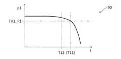
図9に示すように、グラフ90に示すケースでは、図7に示すグラフ70のケースと同様に、異常判定基準52(p1<TH1_P1を異常と判定)は適切に設定されているとする。しかし、保守が実施された保守対応日時T12は、アラームが発生すると想定される日時T11よりも早い時期である。
これは、過剰保守という状況ではあるものの、異常判定結果照合部56において、予め定められたリードタイムを用いて保守対応日時T12とアラーム鳴動予定日時T11との差を照合した際に、差は十分に許容できる水準であるために、機械状態診断部5は適切に機能していると判定される状態である。
従って、図10に示すように、定期保守と判定し、保守作業履歴1001は記録に残るものの、アラーム履歴1002にはアラーム発生の記録がされていないという状況になる。As shown in FIG. 9, in the case shown in the
This is an over-maintenance situation, but when the abnormality determination
Therefore, as shown in FIG. 10, it is determined that the maintenance is regular, and the
次に、図11に示すように、グラフ110に示すケースでも、異常判定基準52(p1<TH1_P1と判定)は図7に示すグラフ70のケースと同様に適切に設定されているとする。また、日時T11にアラームが発生しており、それに従って、定期保守の日時より前であり、機械が故障停止に至る前である日時T13に保守が実施されたという状況である。
このケースでは、異常判定結果照合部56において、予め定められたリードタイムを用いて保守対応日時T13とアラーム鳴動予定日時T11との差を照合しても、その差は十分に許容できる水準であるため、機械状態診断部5は適切に機能していると判定できる事例となる。従って、機械の故障停止前に保守が実施できたという状況であるので、異常判定基準52の設定は適切であり、機械状態診断部5が適切に機能していると判定される状態である。
そのため、図12に示すように、アラーム履歴1202にはアラーム発生が記録されるとともに、定期保守ではないタイミングで保守が実施されたことから、保守作業履歴1201に示すように、「臨時保守」として記録される。Next, as shown in FIG. 11, it is assumed that the abnormality determination reference 52 (determined as p1 <TH1_P1) is appropriately set in the case shown in the
In this case, even if the abnormality determination
For this reason, as shown in FIG. 12, alarm occurrence is recorded in the
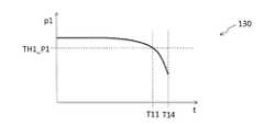
次に、図13に示すように、グラフ130に示すケースでも、異常判定基準52(p1<TH1_P1を異常と判定)は図7に示すグラフ70の場合と同様に適切に設定されているとする。しかし、グラフ130に示すケースでは、日時T11にアラームが発生したものの、鉱山の操業の都合などにより、その後も稼働し続けて、日時T14に機械が故障停止してから保守対応を行ったという状況である。本ケースでは、日時T14は故障日時かつ保守対応日時となり、故障停止と保守日時は同じタイミングである。
そのため、図14に示すように、アラーム履歴1402にはアラーム発生が記録されるとともに、故障してからの保守対応ということで、「故障修理」として保守作業履歴1401が記録される。
本ケースでは、機械状態診断部5によって故障停止前にアラームが出力されているため、機械状態診断部5は適切に機能していると判定される状態である。Next, as shown in FIG. 13, in the case shown in the
Therefore, as shown in FIG. 14, an alarm occurrence is recorded in the
In this case, since the alarm is output by the machine
次に、図15に示すように、グラフ150に示すケースでは、異常判定基準52は適切に設定されていないものであり、異常判定基準52を、p1<TH21_P1からp1<TH22_P1と変更することが推奨されるケースである。
本ケースでは、保守対応が実施された保守対応日時T22の前である日時T21にアラームが出力されている点は図11に示すグラフ110のケースと同じである。しかし、本グラフ150のケースとグラフ110のケースとを比べると、グラフ110のケースではアラーム発生日時T11と保守対応日時T13が比較的近く、また保守は「臨時保守」として実施されている。これに対し、グラフ150のケースでは、異常判定結果照合部56において、予め定められたリードタイムを用いてアラーム発生日時T21と保守対応日時T22との差を照合すると比較的離れていると判定されるため、図16に示すように保守作業履歴1601に「定期保守」として記録される。
このため、保守対応日時T22まで機械が正常に動作したと確認できることから、異常判定基準52は有効に機能しておらず、判定閾値をTH21_P1からTH22_P1に変更した異常判定基準を用いることが適切であると判定される状態となる。
従って、機械状態診断部5の異常判定結果照合部56は、異常判定結果54に相当するアラーム履歴1602と保守作業履歴55に相当する保守作業履歴1601とを照合し、これらアラーム履歴1602と保守作業履歴1601の内容が矛盾して適切でないと判定する。そして、この適切でないとの判定を受けて、異常判定結果照合部56は、更に、予め設定されているリードタイムを用いて、新たな判定閾値TH22_P1を求め、また判定閾値をTH21_P1からTH22_P1に変更した新規の異常判定基準52B「p1<TH22_P1を異常と判定」を演算する。その上で、現行の異常判定基準52Aおよび新規の異常判定基準52Bを出力部59を介して表示装置9に出力し、表示装置9の管理画面に図20に示すような画面を表示させる。Next, as shown in FIG. 15, in the case shown in the
This case is the same as the case of the
For this reason, since it can be confirmed that the machine has operated normally until the maintenance correspondence date and time T22, the abnormality determination standard 52 does not function effectively, and it is appropriate to use the abnormality determination standard in which the determination threshold is changed from TH21_P1 to TH22_P1. It is determined that there is a certain state.
Accordingly, the abnormality determination
ディスパッチャ6や保守員8は、表示装置9の管理画面に表示された現行の異常判定基準52Aおよび新規の異常判定基準52Bとを比較検討し、異常判定基準を変更したほうが良いと判断したときは、機械状態診断部5の入力部58を用いて変更指示部2204において異常判定基準の変更を指示するために「はい」を選択する。入力部58によって、異常判定基準の変更が選択されたとの入力信号がなされたときは、異常判定基準修正部57は、新規の異常判定基準52Bを出力し、機械状態診断部5内部の記憶部50に保持されている異常判定基準52を更新する。
これに対し、ディスパッチャ6や保守員8は、異常判定基準を変更しないほうが良いと判断したときは、異常判定基準の変更は行わないよう変更指示部2204において「いいえ」を選択し、異常判定基準修正部57は新規の異常判定基準52Bを出力せずに処理を終了する。When the dispatcher 6 or the maintenance staff 8 compares the current abnormality determination standard 52A and the new abnormality determination standard 52B displayed on the management screen of the
On the other hand, when the dispatcher 6 or the maintenance staff 8 decides that it is better not to change the abnormality determination standard, the change instruction unit 2204 selects “No” so as not to change the abnormality determination standard, and the abnormality determination standard. The correcting
次に、図17に示すように、グラフ170に示すケースでは、異常判定基準52は適切に設定されていないものであり、異常判定基準52を、p1<TH31_P1からp1<TH33_P1に変更することが推奨されるケースである。
本ケースでは、アラームが出力されると想定される日時T31より前の日時T32に故障停止が発生したという状況である。従って日時T32が保守対応日時となり、図18に示すように、アラームは記録されておらず、保守作業履歴1801は、「故障修理」となっている。
このことから、異常判定基準52は有効に機能しておらず、故障停止をした日時T32よりも一定期間の余裕を持たせた日時T33に対応する検出値T33_P1を判定閾値とした異常判定基準を用いるほうが適切であると判定される状態となる。
従って、図15のグラフ150のケースと同様に、機械状態診断部5の異常判定結果照合部56は、異常判定結果54に相当するアラーム履歴1802と保守作業履歴55に相当する保守作業履歴1801とを照合し、これらアラーム履歴1802と保守作業履歴1801の内容が矛盾して適切でないと判定する。そして、この適切でないとの判定を受けて、異常判定結果照合部56は、更に、予め設定されているリードタイムを用いて判定閾値をTH31_P1からTH33_P1に変更した新規の異常判定基準52B「p1<TH33_P1を異常と判定」を演算する。
その後は、グラフ150のケースと同様に、現行の異常判定基準52Aおよび新規の異常判定基準52Bとを表示装置9に対して出力し、ディスパッチャ6や保守員8による異常判定基準52の変更の要否の判断を仰ぎ、基準の変更を行うまたは変更を行わずに処理を終了する。Next, as shown in FIG. 17, in the case shown in the
In this case, a failure stop has occurred at a date T32 prior to a date T31 at which an alarm is expected to be output. Therefore, the date and time T32 is the maintenance date and time, and as shown in FIG. 18, no alarm is recorded, and the
Therefore, the abnormality determination standard 52 is not functioning effectively, and the abnormality determination standard with the detection value T33_P1 corresponding to the date and time T33 having a certain period of margin as compared to the date and time T32 when the failure was stopped as a determination threshold value. It becomes a state determined to be more appropriate to use.
Accordingly, as in the case of the
After that, as in the case of the
以上の異常判定結果照合部56および異常判定基準修正部57に関わる動作について、図19のフローチャートを用いて説明する。
まず、異常判定結果照合部56は、記憶部50に記憶されている保守作業履歴55を読み出す(ステップS1901)。
次いで、異常判定結果照合部56は、先に読み出した保守作業履歴55を検索し、関連するアラームの有無を確認する(ステップS1902)。このステップS1902における関連するアラームを検索する方法としては、保守作業履歴1001,1201,1401,1601,1801およびアラーム履歴1002,1202,1402,1602,1802に記載された関連センサ信号が一致するかによって判定することが挙げられる。ステップS1902において、関連するアラームがある(上述のグラフ110,130,150)と判定されたときはステップS1903に処理を進め、アラームがない(上述のグラフ90,170)と判定されたときはステップS1905に処理を進める。
ステップS1902において関連するアラームがあると判定されたときは、次に、異常判定結果照合部56は、「保守対応」が「故障修理」であるか否かを判定する(ステップS1903)。「保守対応」が「故障修理」である(上述のグラフ130)と判定されたときは処理を終了し、「保守対応」が「故障修理」でない(上述のグラフ110,150)と判定されたときはステップS1904に処理を進める。
ステップS1903において「保守対応」が「故障修理」でないと判定されたときは、次に、異常判定結果照合部56は、「保守対応」が「定期保守」であるか否かを判定する(ステップS1904)。「保守対応」が「定期保守」である(上述のグラフ150)と判定されたときはステップS1906に処理を進め、「保守対応」が「定期保守」でない(上述のグラフ110)と判定されたときは処理を終了する。
ステップS1904において「定期保守」であると判定されたとき(上述のグラフ150のケース)は、異常判定基準52の変更を行うか否かの判断をディスパッチャ6や保守員8に促すために、異常判定結果照合部56は、更に、予め設定されているリードタイムを用いて、新たな判定閾値および新規の異常判定基準52Bを演算する。その後、現行の異常判定基準52Aおよび新規の異常判定基準52Bを出力部59を介して表示装置9に出力し、表示装置9に図20に示すような画面を表示させる(ステップS1906)。
また、ステップS1902において、関連するアラームがないと判定されたときは、次に、異常判定結果照合部56は、「保守対応」が「故障修理」であるか否かを判定する(ステップS1905)。「保守対応」が「故障修理」でない(上述のグラフ90)と判定されたときは処理を終了し、「保守対応」が「故障修理」である(上述のグラフ170)と判定されたときはステップS1906に処理を進め、ステップS1906の処理を実行する。Operations related to the abnormality determination
First, the abnormality determination
Next, the abnormality determination
If it is determined in step S1902 that there is a related alarm, the abnormality determination
If it is determined in step S1903 that “maintenance response” is not “fault repair”, then the abnormality determination
When it is determined in step S1904 that “periodic maintenance” is indicated (the case of the above-described graph 150), an abnormality is made to prompt the dispatcher 6 or the maintenance staff 8 to determine whether or not to change the
If it is determined in step S1902 that there is no related alarm, then the abnormality determination
上述した本発明の故障診断装置の実施形態は、故障診断装置は、稼働機械の状態異常を検出する装置であり、稼働機械1に搭載され、この稼働機械1の各部品の稼働状態を検知するための各種センサ30と、この各種センサ30から受け取った少なくとも1つのセンサデータ51と異常判定基準52とに基づいて各部品の稼働状態における異常の有無を判定する異常判定部53と、異常判定結果54が適切であるか否か(異常判定結果54に異常があるか否か)を判定し、この判定結果から新規の異常判定基準52Bを求める異常判定結果照合部56と、異常判定部53が異常の有無を判定する際に用いた現行の異常判定基準52A、異常判定結果照合部56によって求められた新規の異常判定基準52Bを表示装置9に出力するための出力部59と、異常判定部53が判定に用いる異常判定基準52を更新する異常判定基準修正部57とを備える。 In the above-described embodiment of the failure diagnosis device of the present invention, the failure diagnosis device is a device that detects an abnormal state of the operating machine and is mounted on the operating machine 1 to detect the operating state of each component of the operating machine 1.
このような構成を備えていることにより、故障診断装置では、異常判定結果54に含まれる誤報や失報に関する情報と稼働機械1の保守作業履歴55と照合して、稼働機械1が正常に稼働していたか、故障停止をしたかといった、異常判定基準52を修正することが推奨される状況であるか否かを判定し、変更したほうが良いと判定したときに現行の異常判定基準52Aと、新規の異常判定基準52Bとを表示装置9に対して出力する。これにより、ディスパッチャ6や保守員8に対して異常判定基準の変更の要否の判断材料を提供することが可能となる。この情報を基にして、ディスパッチャ6や保守員8は、故障診断装置から提供されたこれらの情報を用いて、異常判定基準52を修正したほうが良いかどうかを判断することが可能となり、異常判定基準52の精度に問題がある場合に、その判定をするための異常判定基準52を稼働機械1の可動状況・環境に応じて調整することが可能となる。 By having such a configuration, in the failure diagnosis apparatus, the operating machine 1 operates normally by collating the information on the misinformation or missing information included in the abnormality determination result 54 with the
すなわち、現行の異常判定基準52Aと新規の異常判定基準52Bとを表示装置9で表示させるための出力部59を備えていない従来の故障診断装置では、出荷時に設定した異常判定基準52が正確であることが前提にあり、また非常に高度な判断を要求される異常判定基準52の変更のための判断材料が提供されないため、鉱山などで稼働する稼働機械1の故障診断においては、(1)部品がロット数が少なく高額であるため、様々な条件を模擬した故障試験を行うことが困難である、(2)稼働機械1A,1Bの稼働現場の条件は現場ごとに異なる、(3)同じ現場であっても稼働機械1A,1Bの運転員7の操作状況によって稼働条件が異なる、等の問題に対応することができず、アラームの精度の向上とそれに伴う誤報や失報の低減は困難であった。
これに対し、表示装置9に対して現行の異常判定基準52Aおよび新規の異常判定基準52Bを表示させるための出力部59を備えている本発明の故障診断装置は、非常に高度な判断を要求される異常判定基準52の変更のための判断材料を提供することが可能となり、異常判定基準52の更新を安全かつ正確に実施することができるようになり、アラームの精度向上に大きく寄与する。特に、マイニング分野での上記(1)〜(3)等の特異性に対応できるようになる、との効果を奏する。
また、鉱山などで稼働する稼働機械1の故障診断においては、前述の(1)〜(3)のような問題があるため、異常判定基準52を更新するか否かの判断は非常に慎重に行う必要があることから非常に高度な判断が求められるが、本発明の故障診断装置は、自動で異常判定基準52を更新せずに、ディスパッチャ6や保守員8等の熟練した人間の判断を求めた上で異常判定基準52を更新するため、必要以上に異常判定基準52が更新されず、また異常判定基準52が適切であるか否かを常に監視することができ、アラームの精度の向上により寄与することが可能となるとの効果が得られる。That is, in the conventional failure diagnosis apparatus that does not include the
On the other hand, the fault diagnosis apparatus of the present invention provided with the
Further, in the failure diagnosis of the working machine 1 operating in a mine or the like, there is a problem as described in the above (1) to (3), so the judgment whether or not to update the abnormality determination standard 52 is very careful. Although it is necessary to make a very advanced judgment, the fault diagnosis apparatus of the present invention makes judgments by skilled humans such as the dispatcher 6 and the maintenance staff 8 without automatically updating the
また、異常判定結果照合部56は、異常判定部53によって判定された異常判定結果54と稼働機械の稼働状態を維持するために実施された保守作業履歴55とを用いて、異常判定結果54が適切であるか否かを判定するため、異常判定結果54が適切であるか否かの判定精度をより向上させることができる。 Further, the abnormality determination
更に、異常判定基準修正部57は、出力部59によって表示装置9に表示された現行の異常判定基準52Aと新規の異常判定基準52Bとのいずれかが異常判定部53で用いる異常判定基準52に適しているか、との入力信号をうけて、異常判定部53が判定に用いる異常判定基準52を更新することで、現行の異常判定基準52Aと新規の異常判定基準52Bとの何れが適しているかの判断の入力を受けた上での異常判定基準52の更新がより確実に実施可能となる。 Further, the abnormality determination
また、出力部59によって表示装置9に表示された現行の異常判定基準52Aと新規の異常判定基準52Bとのいずれかが異常判定部53で用いる異常判定基準52に適しているか、を入力するための入力部58を更に備え、異常判定基準修正部57は、入力部58からの入力信号をうけて、異常判定部53が判定に用いる異常判定基準52を更新することにより、現行の異常判定基準52Aと新規の異常判定基準52Bとの何れが適しているかの判断の入力を受けた上での異常判定基準52の更新が更に確実に実施可能となる。 Further, in order to input whether one of the current abnormality determination standard 52A and the new abnormality determination standard 52B displayed on the
また、異常判定結果照合部56は、異常判定結果54が適切でないと判定されたときは、予め設定されたリードタイムを用いて新規の異常判定基準52Bを求めるため、新規の異常判定基準52Bの精度をより高いものとすることができる。 Further, when it is determined that the
また、出力部59は、現行の異常判定基準52A、新規の異常判定基準52Bに加え、更に、異常判定部53が出力する異常判定結果54と、稼働機械の稼働状態を維持するために実施された保守作業履歴55とを表示装置9に出力するため、現行の異常判定基準52Aと新規の異常判定基準52Bとのいずれかが基準にふさわしいかを判断する判断材料をより多く提供することができ、より安全かつ正確な異常判定基準52の変更の要否の判断をするための材料を提供することが可能になる。 In addition to the current abnormality determination standard 52A and the new abnormality determination standard 52B, the
なお、本発明は上記の実施形態に限られず、種々の変形、応用が可能なものである。 In addition, this invention is not restricted to said embodiment, A various deformation | transformation and application are possible.
例えば、稼働機械1は、油圧ショベル1Aやダンプトラック1Bに限られず、鉱山で稼働している機械のすべてに適用可能である。
また、故障診断する部品として油圧ポンプを例示したが、もちろんこれに限定されず、センサ30によってセンシングすることが可能な部品であれば故障診断の対象とすることができる。For example, the operating machine 1 is not limited to the
In addition, although the hydraulic pump is illustrated as a component for failure diagnosis, of course, the present invention is not limited to this, and any component that can be sensed by the
また、保守員8は、機械管理装置3からの情報を受信して表示する携帯端末(図示せず)を保持し、この携帯端末で表示された情報から判断して保守作業や異常判定基準の更新の要否の判断を行うようにしてもよい。 In addition, the maintenance staff 8 holds a portable terminal (not shown) that receives and displays information from the
さらに、図20に示すように、表示装置9の非管理画面には、現行の異常判定基準52A,新規の異常判定基準52B,保守作業履歴2001,アラーム履歴2002に加えて、現行の異常判定基準52Aから新規の異常判定基準52Bに変更すると失報率や誤報率の低減率2003を表示することが望ましい。
この場合、例えば、異常判定結果照合部56は、現行の異常判定基準52Aを用いる時の失報率,誤報率を過去のアラームの出力された日時と現行の異常判定基準52Aにおける判定閾値とから求め、また、新規の異常判定基準52Bを用いる時の失報率,誤報率を過去のアラームの出力された日時と新規の異常判定基準52Bにおける判定閾値とから求めるとともに、現行の異常判定基準52Aを用いる時の失報率,誤報率との差を求め、出力部59を介して表示装置9に表示させる。Further, as shown in FIG. 20, the non-management screen of the
In this case, for example, the abnormality determination
また、上記の実施形態では、故障診断装置のうち各種センサ30を除く大部分の構成を管理事務所2の機械管理装置3が備えている形態について説明したが、稼働機械1の運転員7が十分に熟練している場合などは、図21に示すように、稼働機械1に本発明の故障診断装置の全構成を設けてもよい。
この場合、稼働機械1の運転室に設けた画面に図20に示すような画面を表示させ、運転員7の判断を仰ぐようにする。Moreover, although the said embodiment demonstrated the form with which the
In this case, a screen as shown in FIG. 20 is displayed on the screen provided in the cab of the working machine 1 to ask the
1…稼動機械、
1A…油圧ショベル、
1B…ダンプトラック、
2…管理事務所、
3…機械管理装置、
4…無線通信システム、
4A,4B…無線通信システム、
5…機械状態診断部、
7…運転員、
9…表示装置、
6…ディスパッチャ(管理者)、
8…保守員、
20…車載コントローラ、
202…記憶装置、
201…演算装置、
30…各種センサ、
50…記憶部、
51…判定対象データ、
52…異常判定基準、
52A…現行の異常判定基準、
52B…新規の異常判定基準、
53…異常判定部、
54…異常判定結果、
55…保守作業履歴、
56…異常判定結果照合部、
57…異常判定基準修正部、
58…入力部、
59…出力部、
70,90,110,130,150,170…グラフ、
80…アラーム、
1001,1201,1401,1601,1801,2001…保守作業履歴、
1002,1202,1402,1602,1802,2002…アラーム履歴、
2003…低減率、
2204…変更指示部、
T11,T12,T13,T14,T22,T21,T31,T32,T33…日時、
TH1_P1,TH21_P1,TH22_P1,TH31_P1,TH33_P1…判定閾値、
p1…センサ値。1 ... Working machine,
1A ... hydraulic excavator,
1B ... Dump truck,
2 ... Management office,
3 ... Machine management device,
4 ... Wireless communication system,
4A, 4B ... wireless communication system,
5 ... Machine condition diagnosis part,
7 ... Operator,
9: Display device,
6 ... Dispatcher (administrator),
8 ... maintenance personnel,
20: In-vehicle controller,
202 ... storage device,
201 ... arithmetic device,
30 ... Various sensors,
50 ... storage unit,
51: Determination target data,
52 ... Abnormal judgment criteria,
52A ... current abnormality criteria,
52B ... New abnormality criterion,
53. Abnormality determination unit,
54 ... Abnormal judgment result,
55. Maintenance work history,
56: Abnormality determination result matching unit,
57. An abnormality determination standard correction unit,
58 ... input section,
59 ... output section,
70, 90, 110, 130, 150, 170 ... graph,
80 ... Alarm,
1001, 1201, 1401, 1601, 1801, 2001 ... maintenance work history,
1002, 1202, 1402, 1602, 1802, 2002 ... alarm history,
2003 ... Reduction rate,
2204 ... change instruction section,
T11, T12, T13, T14, T22, T21, T31, T32, T33 ... date and time,
TH1_P1, TH21_P1, TH22_P1, TH31_P1, TH33_P1 ... determination threshold value,
p1: Sensor value.
Claims (7)
Translated fromJapaneseこのセンシング部から受け取った少なくとも1つのセンサデータと異常判定基準とに基づいて前記各部品の稼働状態における異常の有無を判定する異常判定部と、
前記異常判定結果が適切であるか否かを判定し、この判定結果から新規の異常判定基準を求める異常判定結果照合部と、
前記異常判定部が異常の有無を判定する際に用いた現行の異常判定基準、前記異常判定結果照合部によって求められた新規の異常判定基準を表示装置に出力するための出力部と、
前記異常判定部が判定に用いる異常判定基準を更新する異常判定基準修正部とを備えた
ことを特徴とする故障診断装置。A sensing unit mounted on the operating machine for detecting the operating state of each part of the operating machine;
An abnormality determination unit that determines the presence or absence of an abnormality in the operating state of each component based on at least one sensor data and an abnormality determination criterion received from the sensing unit;
It is determined whether or not the abnormality determination result is appropriate, and an abnormality determination result matching unit for obtaining a new abnormality determination criterion from the determination result;
An output unit for outputting the current abnormality determination standard used when the abnormality determination unit determines whether or not there is an abnormality, a new abnormality determination standard obtained by the abnormality determination result verification unit, to a display device;
A failure diagnosis apparatus comprising: an abnormality determination criterion correction unit that updates an abnormality determination criterion used by the abnormality determination unit for determination.
前記異常判定結果照合部は、前記異常判定部によって判定された異常判定結果と前記稼働機械の稼働状態を維持するために実施された保守作業履歴とを用いて前記異常判定結果が適切であるか否かを判定する
ことを特徴とする故障診断装置。The failure diagnosis apparatus according to claim 1 is:
Whether the abnormality determination result collation unit is appropriate using the abnormality determination result determined by the abnormality determination unit and the maintenance work history performed to maintain the operating state of the operating machine. A failure diagnosis apparatus characterized by determining whether or not.
前記異常判定基準修正部は、前記出力部によって前記表示装置に表示された前記現行の異常判定基準と前記新規の異常判定基準とのいずれかが前記異常判定部で用いる異常判定基準に適しているか、の入力信号をうけて、前記異常判定部が判定に用いる異常判定基準を更新する
ことを特徴とする故障診断装置。The failure diagnosis apparatus according to claim 1,
Whether the abnormality determination criterion correction unit is suitable for the abnormality determination criterion used by the abnormality determination unit, either the current abnormality criterion displayed on the display device by the output unit or the new abnormality criterion In response to the input signal, the abnormality determination standard used for determination by the abnormality determination unit is updated.
前記出力部によって前記表示装置に表示された前記現行の異常判定基準と前記新規の異常判定基準とのいずれかが前記異常判定部で用いる異常判定基準に適しているか、を入力するための入力部を更に備え、
前記異常判定基準修正部は、前記入力部からの入力信号をうけて、前記異常判定部が判定に用いる異常判定基準を更新する
ことを特徴とする故障診断装置。In the failure diagnosis apparatus according to claim 3,
An input unit for inputting whether either the current abnormality determination criterion or the new abnormality determination criterion displayed on the display device by the output unit is suitable for the abnormality determination criterion used in the abnormality determination unit Further comprising
The failure diagnosis apparatus according to claim 1, wherein the abnormality determination reference correction unit updates an abnormality determination reference used by the abnormality determination unit for determination in response to an input signal from the input unit.
前記異常判定結果照合部は、前記異常判定結果が適切でないと判定されたときは、予め設定されたリードタイムを用いて新規の異常判定基準を求める
ことを特徴とする故障診断装置。The failure diagnosis apparatus according to claim 1,
The abnormality diagnosis result collating unit obtains a new abnormality determination criterion using a preset lead time when it is determined that the abnormality determination result is not appropriate.
前記出力部は、前記現行の異常判定基準、前記新規の異常判定基準に加え、更に、前記異常判定部が出力する異常判定結果と、前記稼働機械の稼働状態を維持するために実施された保守作業履歴とを前記表示装置に出力する
ことを特徴とする故障診断装置。The failure diagnosis apparatus according to claim 1,
In addition to the current abnormality determination standard and the new abnormality determination standard, the output unit further performs an abnormality determination result output by the abnormality determination unit and maintenance performed to maintain the operating state of the operating machine. A failure diagnosis device that outputs a work history to the display device.
Priority Applications (1)
| Application Number | Priority Date | Filing Date | Title |
|---|---|---|---|
| JP2013222598AJP2015084176A (en) | 2013-10-25 | 2013-10-25 | Fault diagnostic apparatus and active machine |
Applications Claiming Priority (1)
| Application Number | Priority Date | Filing Date | Title |
|---|---|---|---|
| JP2013222598AJP2015084176A (en) | 2013-10-25 | 2013-10-25 | Fault diagnostic apparatus and active machine |
Publications (1)
| Publication Number | Publication Date |
|---|---|
| JP2015084176Atrue JP2015084176A (en) | 2015-04-30 |
Family
ID=53047745
Family Applications (1)
| Application Number | Title | Priority Date | Filing Date |
|---|---|---|---|
| JP2013222598APendingJP2015084176A (en) | 2013-10-25 | 2013-10-25 | Fault diagnostic apparatus and active machine |
Country Status (1)
| Country | Link |
|---|---|
| JP (1) | JP2015084176A (en) |
Cited By (4)
| Publication number | Priority date | Publication date | Assignee | Title |
|---|---|---|---|---|
| WO2018042982A1 (en)* | 2016-08-31 | 2018-03-08 | 日立工機株式会社 | Failure diagnosis system and management system |
| CN112733369A (en)* | 2021-01-13 | 2021-04-30 | 青岛海尔科技有限公司 | Intelligent equipment maintenance method, terminal and system and electronic equipment |
| JP2024033623A (en)* | 2022-08-30 | 2024-03-13 | 日立Geニュークリア・エナジー株式会社 | Plant function management support method and plant function management support device |
| JP7511780B1 (en)* | 2023-06-23 | 2024-07-05 | 三菱電機株式会社 | Maintenance schedule management system, maintenance schedule management device, control method and control program |
Citations (6)
| Publication number | Priority date | Publication date | Assignee | Title |
|---|---|---|---|---|
| JPH06309585A (en)* | 1993-04-26 | 1994-11-04 | Mitsubishi Electric Corp | Pre-alarm device |
| JPH11175134A (en)* | 1997-12-16 | 1999-07-02 | Mitsubishi Electric Corp | Plant preventive maintenance system and plant preventive maintenance method |
| US20050267702A1 (en)* | 2004-05-28 | 2005-12-01 | General Electric Company | Method for developing a unified quality assessment and providing an automated fault diagnostic tool for turbine machine systems and the like |
| JP2005339142A (en)* | 2004-05-26 | 2005-12-08 | Tokyo Electric Power Co Inc:The | Equipment maintenance support equipment |
| JP2012094044A (en)* | 2010-10-28 | 2012-05-17 | Hitachi Ltd | Abnormality diagnosis device and industrial machine |
| JP2013041448A (en)* | 2011-08-17 | 2013-02-28 | Hitachi Ltd | Method of abnormality detection/diagnosis and system of abnormality detection/diagnosis |
- 2013
- 2013-10-25JPJP2013222598Apatent/JP2015084176A/enactivePending
Patent Citations (6)
| Publication number | Priority date | Publication date | Assignee | Title |
|---|---|---|---|---|
| JPH06309585A (en)* | 1993-04-26 | 1994-11-04 | Mitsubishi Electric Corp | Pre-alarm device |
| JPH11175134A (en)* | 1997-12-16 | 1999-07-02 | Mitsubishi Electric Corp | Plant preventive maintenance system and plant preventive maintenance method |
| JP2005339142A (en)* | 2004-05-26 | 2005-12-08 | Tokyo Electric Power Co Inc:The | Equipment maintenance support equipment |
| US20050267702A1 (en)* | 2004-05-28 | 2005-12-01 | General Electric Company | Method for developing a unified quality assessment and providing an automated fault diagnostic tool for turbine machine systems and the like |
| JP2012094044A (en)* | 2010-10-28 | 2012-05-17 | Hitachi Ltd | Abnormality diagnosis device and industrial machine |
| JP2013041448A (en)* | 2011-08-17 | 2013-02-28 | Hitachi Ltd | Method of abnormality detection/diagnosis and system of abnormality detection/diagnosis |
Cited By (6)
| Publication number | Priority date | Publication date | Assignee | Title |
|---|---|---|---|---|
| WO2018042982A1 (en)* | 2016-08-31 | 2018-03-08 | 日立工機株式会社 | Failure diagnosis system and management system |
| CN112733369A (en)* | 2021-01-13 | 2021-04-30 | 青岛海尔科技有限公司 | Intelligent equipment maintenance method, terminal and system and electronic equipment |
| CN112733369B (en)* | 2021-01-13 | 2023-06-13 | 青岛海尔科技有限公司 | Intelligent equipment maintenance method, terminal and system and electronic equipment |
| JP2024033623A (en)* | 2022-08-30 | 2024-03-13 | 日立Geニュークリア・エナジー株式会社 | Plant function management support method and plant function management support device |
| JP7699565B2 (en) | 2022-08-30 | 2025-06-27 | 日立Geニュークリア・エナジー株式会社 | Plant function management support method and plant function management support device |
| JP7511780B1 (en)* | 2023-06-23 | 2024-07-05 | 三菱電機株式会社 | Maintenance schedule management system, maintenance schedule management device, control method and control program |
Similar Documents
| Publication | Publication Date | Title |
|---|---|---|
| CN110023862B (en) | Diagnostic device, diagnostic method, and computer-readable recording medium | |
| WO2012057001A1 (en) | Anomaly diagnostic device and industrial machine | |
| US10235658B2 (en) | Maintenance management device for operating machinery | |
| US11892828B2 (en) | Fault diagnosis device, fault diagnosis method and machine to which fault diagnosis device is applied | |
| US7117119B2 (en) | System and method for continuous online safety and reliability monitoring | |
| CN111819042B (en) | Abnormality detection device and abnormality detection method | |
| US9765690B2 (en) | Variable geometry turbocharger prognostics | |
| JPWO2019167171A6 (en) | Anomaly detection device and abnormality detection method | |
| JP2015084176A (en) | Fault diagnostic apparatus and active machine | |
| WO2017138238A1 (en) | Monitoring device, and method for controlling monitoring device | |
| JP6540532B2 (en) | Monitoring device and control method of monitoring device | |
| WO2014054051A1 (en) | Health monitoring system for a process plant and a method thereof | |
| JP2022072229A (en) | Device diagnostic system, device diagnostic method, and program | |
| JP5485441B2 (en) | Abnormality diagnosis device and industrial machine | |
| KR20140072331A (en) | Method for preliminary surveillance of failure diagnosis | |
| US20250164974A1 (en) | Production Management Device, Production Management System, and Production Management Method | |
| EP3417262B1 (en) | Predictive monitoring system and method | |
| US20170038281A1 (en) | Method of predicting life of component of machine | |
| JP2011107760A (en) | Device of detecting plant abnormality | |
| US20160170395A1 (en) | Case management linkage of updates, evidence, and triggers | |
| US20200122859A1 (en) | Predictive monitoring system and method | |
| US10955829B2 (en) | System and a method to enable zero defect production | |
| WO2021191916A1 (en) | A system and a method to enable zero defect production |
Legal Events
| Date | Code | Title | Description |
|---|---|---|---|
| A621 | Written request for application examination | Free format text:JAPANESE INTERMEDIATE CODE: A621 Effective date:20160502 | |
| RD02 | Notification of acceptance of power of attorney | Free format text:JAPANESE INTERMEDIATE CODE: A7422 Effective date:20160502 | |
| A977 | Report on retrieval | Free format text:JAPANESE INTERMEDIATE CODE: A971007 Effective date:20170209 | |
| A131 | Notification of reasons for refusal | Free format text:JAPANESE INTERMEDIATE CODE: A131 Effective date:20170221 | |
| A02 | Decision of refusal | Free format text:JAPANESE INTERMEDIATE CODE: A02 Effective date:20170829 |