JP2015073826A - Biological information measuring device - Google Patents
Biological information measuring deviceDownload PDFInfo
- Publication number
- JP2015073826A JP2015073826AJP2013213480AJP2013213480AJP2015073826AJP 2015073826 AJP2015073826 AJP 2015073826AJP 2013213480 AJP2013213480 AJP 2013213480AJP 2013213480 AJP2013213480 AJP 2013213480AJP 2015073826 AJP2015073826 AJP 2015073826A
- Authority
- JP
- Japan
- Prior art keywords
- biological information
- measuring device
- subject
- main body
- unit
- Prior art date
- Legal status (The legal status is an assumption and is not a legal conclusion. Google has not performed a legal analysis and makes no representation as to the accuracy of the status listed.)
- Pending
Links
- 238000012545processingMethods0.000claimsabstractdescription57
- 238000001514detection methodMethods0.000claimsdescription57
- 238000005259measurementMethods0.000claimsdescription36
- 230000008859changeEffects0.000claimsdescription30
- 238000004891communicationMethods0.000description30
- 230000000694effectsEffects0.000description16
- 239000000463materialSubstances0.000description13
- 238000003780insertionMethods0.000description12
- 230000037431insertionEffects0.000description12
- 210000000707wristAnatomy0.000description12
- PXHVJJICTQNCMI-UHFFFAOYSA-NNickelChemical compound[Ni]PXHVJJICTQNCMI-UHFFFAOYSA-N0.000description7
- 210000003811fingerAnatomy0.000description7
- 238000003825pressingMethods0.000description6
- HBBGRARXTFLTSG-UHFFFAOYSA-NLithium ionChemical compound[Li+]HBBGRARXTFLTSG-UHFFFAOYSA-N0.000description5
- 230000007797corrosionEffects0.000description5
- 238000005260corrosionMethods0.000description5
- 229910001416lithium ionInorganic materials0.000description5
- 238000000034methodMethods0.000description5
- 230000008602contractionEffects0.000description4
- 230000010365information processingEffects0.000description4
- 210000003813thumbAnatomy0.000description4
- 230000001154acute effectEffects0.000description3
- 229910052759nickelInorganic materials0.000description3
- 230000002093peripheral effectEffects0.000description3
- 229910001220stainless steelInorganic materials0.000description3
- 239000010935stainless steelSubstances0.000description3
- 238000005452bendingMethods0.000description2
- 230000004397blinkingEffects0.000description2
- 239000004020conductorSubstances0.000description2
- 238000013461designMethods0.000description2
- 230000006866deteriorationEffects0.000description2
- 238000005401electroluminescenceMethods0.000description2
- 239000011521glassSubstances0.000description2
- 238000009532heart rate measurementMethods0.000description2
- 239000004973liquid crystal related substanceSubstances0.000description2
- 229920005749polyurethane resinPolymers0.000description2
- 230000000284resting effectEffects0.000description2
- 238000004904shorteningMethods0.000description2
- 229920002050silicone resinPolymers0.000description2
- 239000000758substrateSubstances0.000description2
- 229920003002synthetic resinPolymers0.000description2
- 239000000057synthetic resinSubstances0.000description2
- 239000004925Acrylic resinSubstances0.000description1
- 229920000178Acrylic resinPolymers0.000description1
- 239000004677NylonSubstances0.000description1
- 230000002411adverseEffects0.000description1
- 230000006399behaviorEffects0.000description1
- 230000008901benefitEffects0.000description1
- 210000004204blood vesselAnatomy0.000description1
- 238000006073displacement reactionMethods0.000description1
- PCHJSUWPFVWCPO-UHFFFAOYSA-NgoldChemical compound[Au]PCHJSUWPFVWCPO-UHFFFAOYSA-N0.000description1
- 239000010931goldSubstances0.000description1
- 229910052737goldInorganic materials0.000description1
- 230000001788irregularEffects0.000description1
- 239000011159matrix materialSubstances0.000description1
- 229910052751metalInorganic materials0.000description1
- 239000002184metalSubstances0.000description1
- 229920001778nylonPolymers0.000description1
- 230000003287optical effectEffects0.000description1
- 239000012466permeateSubstances0.000description1
- 239000000088plastic resinSubstances0.000description1
- 238000007747platingMethods0.000description1
- 229920000642polymerPolymers0.000description1
- 230000008569processEffects0.000description1
- 229920005989resinPolymers0.000description1
- 239000011347resinSubstances0.000description1
- 238000005070samplingMethods0.000description1
- 210000002374sebumAnatomy0.000description1
- 239000004065semiconductorSubstances0.000description1
- 230000000007visual effectEffects0.000description1
- 239000013585weight reducing agentSubstances0.000description1
Images


Classifications
- A—HUMAN NECESSITIES
- A61—MEDICAL OR VETERINARY SCIENCE; HYGIENE
- A61B—DIAGNOSIS; SURGERY; IDENTIFICATION
- A61B5/00—Measuring for diagnostic purposes; Identification of persons
- A61B5/02—Detecting, measuring or recording for evaluating the cardiovascular system, e.g. pulse, heart rate, blood pressure or blood flow
- A61B5/024—Measuring pulse rate or heart rate
- A61B5/02438—Measuring pulse rate or heart rate with portable devices, e.g. worn by the patient
- A—HUMAN NECESSITIES
- A61—MEDICAL OR VETERINARY SCIENCE; HYGIENE
- A61B—DIAGNOSIS; SURGERY; IDENTIFICATION
- A61B5/00—Measuring for diagnostic purposes; Identification of persons
- A—HUMAN NECESSITIES
- A61—MEDICAL OR VETERINARY SCIENCE; HYGIENE
- A61B—DIAGNOSIS; SURGERY; IDENTIFICATION
- A61B5/00—Measuring for diagnostic purposes; Identification of persons
- A61B5/68—Arrangements of detecting, measuring or recording means, e.g. sensors, in relation to patient
- A61B5/6801—Arrangements of detecting, measuring or recording means, e.g. sensors, in relation to patient specially adapted to be attached to or worn on the body surface
- A61B5/6802—Sensor mounted on worn items
- A61B5/681—Wristwatch-type devices
- A—HUMAN NECESSITIES
- A61—MEDICAL OR VETERINARY SCIENCE; HYGIENE
- A61B—DIAGNOSIS; SURGERY; IDENTIFICATION
- A61B5/00—Measuring for diagnostic purposes; Identification of persons
- A61B5/72—Signal processing specially adapted for physiological signals or for diagnostic purposes
- A61B5/7271—Specific aspects of physiological measurement analysis
- A61B5/7285—Specific aspects of physiological measurement analysis for synchronizing or triggering a physiological measurement or image acquisition with a physiological event or waveform, e.g. an ECG signal
- G—PHYSICS
- G04—HOROLOGY
- G04G—ELECTRONIC TIME-PIECES
- G04G21/00—Input or output devices integrated in time-pieces
- G04G21/02—Detectors of external physical values, e.g. temperature
- G04G21/025—Detectors of external physical values, e.g. temperature for measuring physiological data
- A—HUMAN NECESSITIES
- A61—MEDICAL OR VETERINARY SCIENCE; HYGIENE
- A61B—DIAGNOSIS; SURGERY; IDENTIFICATION
- A61B2560/00—Constructional details of operational features of apparatus; Accessories for medical measuring apparatus
- A61B2560/02—Operational features
- A61B2560/0204—Operational features of power management
- A61B2560/0209—Operational features of power management adapted for power saving
- A—HUMAN NECESSITIES
- A61—MEDICAL OR VETERINARY SCIENCE; HYGIENE
- A61B—DIAGNOSIS; SURGERY; IDENTIFICATION
- A61B2560/00—Constructional details of operational features of apparatus; Accessories for medical measuring apparatus
- A61B2560/02—Operational features
- A61B2560/0204—Operational features of power management
- A61B2560/0214—Operational features of power management of power generation or supply
- A—HUMAN NECESSITIES
- A61—MEDICAL OR VETERINARY SCIENCE; HYGIENE
- A61B—DIAGNOSIS; SURGERY; IDENTIFICATION
- A61B5/00—Measuring for diagnostic purposes; Identification of persons
- A61B5/02—Detecting, measuring or recording for evaluating the cardiovascular system, e.g. pulse, heart rate, blood pressure or blood flow
- A61B5/024—Measuring pulse rate or heart rate
Landscapes
- Health & Medical Sciences (AREA)
- Life Sciences & Earth Sciences (AREA)
- Physics & Mathematics (AREA)
- Biophysics (AREA)
- General Health & Medical Sciences (AREA)
- Engineering & Computer Science (AREA)
- Biomedical Technology (AREA)
- Medical Informatics (AREA)
- Molecular Biology (AREA)
- Surgery (AREA)
- Animal Behavior & Ethology (AREA)
- Pathology (AREA)
- Public Health (AREA)
- Veterinary Medicine (AREA)
- Heart & Thoracic Surgery (AREA)
- Physiology (AREA)
- General Physics & Mathematics (AREA)
- Cardiology (AREA)
- Artificial Intelligence (AREA)
- Signal Processing (AREA)
- Psychiatry (AREA)
- Computer Vision & Pattern Recognition (AREA)
- Measuring Pulse, Heart Rate, Blood Pressure Or Blood Flow (AREA)
- Measuring And Recording Apparatus For Diagnosis (AREA)
- Measurement Of The Respiration, Hearing Ability, Form, And Blood Characteristics Of Living Organisms (AREA)
Abstract
Translated fromJapaneseDescription
Translated fromJapanese本発明は、被検体の生体情報を測定する生体情報測定機器に関する。 The present invention relates to a biological information measuring device that measures biological information of a subject.
従来、装着者の手首等に装着され、脈拍等の生体情報を測定する測定機器や、当該生体情報の測定機能を有する腕時計等の電子機器が知られている。このような電子機器では、装着者における手首等の適当な部位に、測定をおこなう機器本体を密着させる必要がある。 2. Description of the Related Art Conventionally, measurement devices that are worn on a wearer's wrist or the like and measure biological information such as a pulse, and electronic devices such as a wristwatch that has a function of measuring the biological information are known. In such an electronic apparatus, it is necessary to closely attach the apparatus main body to be measured to an appropriate part such as a wrist of the wearer.
この特許文献1に記載された生体情報測定機器は、機器本体に取り付けられる第1バンド部材および第2バンド部材と、連結部材とを備える。各バンド部材は、バンド延出方向に沿って伸縮する伸縮部を備え、伸縮部は、可撓性を有し、幅方向に沿う一対のスリット、およびバンド延出方向に沿うスリットを有する第1スリットと、幅方向に沿って伸縮部の外部に連通する一対の第2スリットを有する。連結部材は、固定部材と、第1バンド部材のバンド延出方向に沿ってスライド可能なスライド部材と、スライド部材を当該バンド延出方向とは反対方向に付勢する付勢部材とを備え、スライド部材は、第2バンド部材と連結される連結部(突棒)を備える。また、このような生体情報測定機器には、生体情報の測定をおこなうためのセンサーや電子回路を駆動させる電源が搭載されている。特許文献1では、電源部として充電可能な電池を備え、電池は被検体に装着される機器本体に搭載されているものが開示されている。 The biological information measuring device described in Patent Literature 1 includes a first band member and a second band member that are attached to the device main body, and a connecting member. Each band member includes an expansion / contraction part that expands and contracts along the band extending direction, and the expansion / contraction part has flexibility, and includes a pair of slits along the width direction and a slit along the band extending direction. A slit and a pair of second slits communicating with the outside of the stretchable portion along the width direction are provided. The connecting member includes a fixing member, a slide member that can slide along the band extending direction of the first band member, and a biasing member that biases the slide member in a direction opposite to the band extending direction. A slide member is provided with the connection part (projection stick) connected with the 2nd band member. Such a biological information measuring device is equipped with a power source for driving a sensor and an electronic circuit for measuring biological information. Patent Document 1 discloses a battery that can be charged as a power supply unit, and the battery is mounted on an apparatus main body that is mounted on a subject.
しかしながら、上述した特許文献1に記載の生体情報測定機器は、生体情報を検出する頻度を高めると電池の消耗が促進され、また大きな画面の表示部を使用するためにさらに電力が消耗されるために、測定時間が短くなるという課題があった。また、電池の容量を大きくすると、測定時間を長時間にすることはできるが、機器本体の重量と外形の大きさが増し、装着による疲労感を被検体に与えるという課題もあった。また、生体情報測定機器の機器本体部分の重量が大きい場合には、運動時の生体情報測定に悪影響を及ぼしてしまう虞があった。そして、生体情報測定機器の機器本体部分の厚みや体積が必要以上に大きい場合には、機器本体が大きく視認されることから視覚的な圧迫感を被検体に与えてしまうために、長時間連続して生体情報をすることが難しいという課題もあった。 However, in the biological information measuring device described in Patent Document 1 described above, if the frequency of detecting biological information is increased, the consumption of the battery is promoted, and the power is further consumed because the large screen display unit is used. In addition, there is a problem that the measurement time is shortened. Further, when the battery capacity is increased, the measurement time can be extended, but there is a problem that the weight of the device main body and the size of the outer shape are increased, and fatigue due to wearing is given to the subject. In addition, when the weight of the device main body of the biological information measuring device is large, there is a risk of adversely affecting the biological information measurement during exercise. And when the thickness and volume of the main body part of the biological information measuring device are larger than necessary, the device main body is visually recognized greatly, so that a visual feeling of pressure is given to the subject. Therefore, there is a problem that it is difficult to perform biometric information.
本発明は、上述した課題の少なくとも一部を解決するためになされたものであり、以下の形態、または適用例として実現することが可能である。 SUMMARY An advantage of some aspects of the invention is to solve at least a part of the problems described above, and the invention can be implemented as the following forms or application examples.
[適用例1]
本適用例に係る生体情報測定機器は、被検体の生体情報を検出するセンサー部と、生体情報の処理をおこなう処理部と、センサー部、および処理部に電力を供給する電源部と、センサー部、処理部、および電源部が収容されたケース部を有する機器本体と、機器本体を被検体に装着するバンド部と、を備え、機器本体の重量は60g以下であり、10時間以上連続して生体情報を測定することができることを特徴とする。[Application Example 1]
A biological information measuring device according to this application example includes a sensor unit that detects biological information of a subject, a processing unit that performs processing of biological information, a sensor unit, a power supply unit that supplies power to the processing unit, and a sensor unit , A processing unit, and a device main unit having a case unit in which the power supply unit is accommodated, and a band unit for mounting the device main unit on the subject. Biometric information can be measured.
このような生体情報測定機器によれば、バンドによって被検体に装着された機器本体に設けられているセンサー部によって、当該被検体の生体情報を測定することができる。また、生体情報測定機器は、10時間以上連続して生体情報を測定することができる電源を供給することが可能な電源部を備え、機器本体の重量が60g以下である。したがって、被検体の運動による慣性力が当該被検体および機器本体に作用することを抑制し、精度の高い生体情報を10時間以上連続して測定することができる。また、長時間装着しても圧迫感や疲労感を被検体に与えることを抑制した生体情報測定機器を実現することができる。 According to such a biological information measuring device, the biological information of the subject can be measured by the sensor unit provided in the device main body attached to the subject by the band. In addition, the biological information measuring device includes a power supply unit capable of supplying power that can continuously measure biological information for 10 hours or more, and the weight of the device main body is 60 g or less. Therefore, it is possible to suppress the inertial force due to the movement of the subject from acting on the subject and the apparatus main body, and to measure highly accurate biological information continuously for 10 hours or more. In addition, it is possible to realize a biological information measuring device that suppresses giving a subject a feeling of pressure or fatigue even when worn for a long time.
[適用例2]
上記適用例に係る生体情報測定機器は、センサー部による生体情報の検出を間欠的に行うことが好ましい。[Application Example 2]
It is preferable that the biological information measuring device according to the application example described above intermittently detects biological information by the sensor unit.
このような生体情報測定機器によれば、センサー部による生体情報の検出は、処理部で制御されることで、被検体の状況に応じて、必要なレートで間欠的におこなわれる。したがって、センサー部や処理部に供給される電源は間欠的に消費される。よって、消費電力を抑制し、生体情報を連続して測定することができる時間を長くすること可能な生体情報測定機器を実現することができる。 According to such a biological information measuring device, detection of biological information by the sensor unit is intermittently performed at a necessary rate according to the condition of the subject by being controlled by the processing unit. Therefore, the power supplied to the sensor unit and the processing unit is consumed intermittently. Therefore, it is possible to realize a biological information measuring device capable of suppressing power consumption and extending the time during which biological information can be continuously measured.
[適用例3]
上記適用例に係る生体情報測定機器は、検出された生体情報に基づき、検出をおこなう時間間隔を可変させることが好ましい。[Application Example 3]
The biological information measuring device according to the application example described above preferably varies the time interval for detection based on the detected biological information.
このような生体情報測定機器は、センサー部による生体情報の検出をおこなう時間間隔を可変できる。したがって、検出された生体情報に基づいて検出をおこなう時間間隔を延ばすことで、さらに消費電力を抑制しつつ、測定可能な時間を長くすることができる生体情報測定機器を実現することができる。 Such a biological information measuring device can vary the time interval for detecting the biological information by the sensor unit. Therefore, by extending the time interval for performing detection based on the detected biological information, it is possible to realize a biological information measuring device capable of extending the measurable time while further reducing power consumption.
[適用例4]
上記適用例に係る生体情報測定機器は、被検体の安静時の生体情報を記憶し、安静時の生体情報と比して、検出された生体情報の変化が小さいときは時間間隔を延ばし、検出された生体情報の変化が大きいときに時間間隔を縮めることが好ましい。[Application Example 4]
The biological information measuring device according to the application example stores biological information at rest of the subject, and when the change in detected biological information is small compared to the biological information at rest, the time interval is extended and detected. It is preferable to shorten the time interval when the change in the biometric information is large.
このような生体情報測定機器によれば、安静時の生体情報と比して、検出された生体情報の変化が小さいときは、生体情報を検出する時間間隔を延ばすことができる。時間間隔を延ばすことで、生体情報測定機器における消費電力を抑制することができる。また、安静時の生体情報と比して、検出された生体情報の変化が大きいときは、生体情報を検出する時間間隔を縮めることができる。時間間隔を縮めることで、より精細な生体情報の変化を得ることができる。したがって、精細かつ消費電力を抑制し長時間の測定を可能とした生体情報測定機器を実現することができる。 According to such a biological information measuring device, when the change of the detected biological information is small compared to the biological information at rest, the time interval for detecting the biological information can be extended. By extending the time interval, power consumption in the biological information measurement device can be suppressed. Moreover, when the change of the detected biometric information is large compared to the biometric information at rest, the time interval for detecting the biometric information can be shortened. By reducing the time interval, more detailed changes in biological information can be obtained. Therefore, it is possible to realize a biological information measuring device that is fine and suppresses power consumption and enables long-time measurement.
[適用例5]
上記適用例に係る生体情報測定機器の電源部には、充電可能な電池を備え、前回の充電後に行われた生体情報の検出回数や測定時間に応じて電池の充電量を決定することが好ましい。[Application Example 5]
The power supply unit of the biological information measuring device according to the application example described above preferably includes a rechargeable battery, and determines the amount of charge of the battery according to the number of times biometric information is detected and measured after the previous charging. .
このような生体情報測定機器によれば、電源部として充電可能な電池を用いることから被検体への機器本体の装着が容易である。また、前回の充電後におこなわれた生体情報の検出回数や測定時間に応じて電池の充電量を決定するため、充電時間の短縮化と、電池の劣化を抑制することができる。したがって、被検体への装着に適した生体情報測定機器を実現することができる。 According to such a biological information measuring device, since a rechargeable battery is used as the power supply unit, it is easy to attach the device main body to the subject. In addition, since the amount of charge of the battery is determined according to the number of times biometric information is detected and the measurement time performed after the previous charge, shortening of the charge time and deterioration of the battery can be suppressed. Therefore, it is possible to realize a biological information measuring device suitable for mounting on the subject.
[適用例6]
上記適用例に係る生体情報測定機器は、所望の検出回数や測定時間に応じて予め電池の充電量を設定し、電池の充電をおこなうことが好ましい。[Application Example 6]
It is preferable that the biological information measuring device according to the application example described above sets the charge amount of the battery in advance according to the desired number of detections and measurement time, and charges the battery.
このような生体情報測定機器は、所望の検出回数や測定時間に応じて充電量を予め設定し、電池の充電をおこなうことで、予め生体情報が得られていない場合や、被検体が異なる場合にも適正な充電をおこない、生体情報の測定をおこなうことができる。 Such a biological information measuring device sets the amount of charge in advance according to the desired number of detections and measurement time, and charges the battery so that biological information is not obtained in advance or the subject is different In addition, it is possible to perform proper charging and measure biological information.
[適用例7]
上記適用例に係る生体情報測定機器は、充電後におこなう検出回数や測定時間に応じて、搭載される電池の容量が選択されることが好ましい。[Application Example 7]
In the biological information measuring device according to the application example described above, it is preferable that the capacity of the battery to be mounted is selected according to the number of detections performed after charging and the measurement time.
このような生体情報測定機器は、充電後におこなう生体情報の検出回数や測定時間に応じて搭載される電池の容量が選択されている。すなわち、1回の充電で欲する生体情報の検出回数に応じて電池の容量が選択されている。したがって、測定期間が短時間で検出回数が少ない場合には小容量の電池を選択することで、被検体に装着される機器本体を軽量化と、被検体への圧迫感を緩和することができる。また、測定期間が長時間で検出回数が多い場合には大容量の電池を選択することで、連続して被検体の生体情報を測定することができ、より精細な生体情報を得ることができる。 In such a biological information measuring device, the capacity of a battery to be mounted is selected according to the number of times biological information is detected after charging and the measurement time. That is, the capacity of the battery is selected according to the number of detections of biometric information desired in one charge. Therefore, when the measurement period is short and the number of detections is small, a battery with a small capacity can be selected to reduce the weight of the device body attached to the subject and reduce the feeling of pressure on the subject. . In addition, when the measurement period is long and the number of detections is large, by selecting a battery with a large capacity, it is possible to continuously measure the biological information of the subject and obtain more detailed biological information. .
[適用例8]
上記適用例に係る生体情報測定機器は、電池の充電量に応じて、検出をおこなう時間間隔を可変させることが好ましい。[Application Example 8]
The biological information measuring device according to the application example described above preferably varies the time interval for detection according to the amount of charge of the battery.
このような生体情報測定機器は、電池の充電量に応じて、生体情報を検出する時間間隔を可変できる。したがって、電池の充電量に余裕があるときは検出する時間間隔を縮めることで、生体情報の変化が大きいときに精細に生体情報の検出をおこなうことができる。また、電池の充電量が少ないときは検出する時間間隔を延ばすことで、長時間にわたり生体情報を測定することができる。したがって、電池の充電量に応じた最適な時間間隔で生体情報を検出することができる。 Such a biological information measuring device can vary the time interval for detecting biological information according to the amount of charge of the battery. Therefore, when the amount of charge of the battery has a margin, the detection time interval is shortened, so that the biological information can be detected finely when the change in the biological information is large. In addition, when the amount of charge of the battery is small, the biological information can be measured over a long time by extending the detection time interval. Therefore, biometric information can be detected at an optimal time interval according to the amount of charge of the battery.
[適用例9]
本適用例に係る生体情報測定機器は、被検体の生体情報を検出するセンサー部と、生体情報の処理をおこなう処理部と、センサー部、および処理部に電力を供給する電源部と、センサー部、処理部、および電源部が収容されたケース部を有する機器本体と、機器本体を被検体に装着するバンドと、を備え、生体情報測定機器の機器本体の体積は50cc以下であり、10時間以上連続して生体情報を測定することができることを特徴とする。[Application Example 9]
A biological information measuring device according to this application example includes a sensor unit that detects biological information of a subject, a processing unit that performs processing of biological information, a sensor unit, a power supply unit that supplies power to the processing unit, and a sensor unit An apparatus main body having a case section in which the processing section and the power supply section are housed, and a band for mounting the apparatus main body on the subject. The volume of the apparatus main body of the biological information measuring apparatus is 50 cc or less, and 10 hours. The biometric information can be measured continuously as described above.
このような生体情報測定機器によれば、バンドによって被検体に装着された機器本体に設けられているセンサー部によって、当該被検体の生体情報を測定することができる。また、生体情報測定機器は、10時間以上連続して生体情報を測定することができる電源を供給することが可能な電源部を備え、機器本体の体積が50cc以下である。したがって、被検体が運動する際に、着衣に機器本体が引っかかることを抑制し、精度の高い生体情報を10時間以上連続して測定することができる。また、長時間装着しても圧迫感や疲労感を被検体に与えることを抑制した生体情報測定機器を実現することができる。 According to such a biological information measuring device, the biological information of the subject can be measured by the sensor unit provided in the device main body attached to the subject by the band. In addition, the biological information measuring device includes a power supply unit capable of supplying power that can measure biological information continuously for 10 hours or more, and the volume of the device main body is 50 cc or less. Therefore, when the subject exercises, it is possible to suppress the device body from being caught by the clothes, and to measure highly accurate biological information continuously for 10 hours or more. In addition, it is possible to realize a biological information measuring device that suppresses giving a subject a feeling of pressure or fatigue even when worn for a long time.
[適用例10]
上記適用例に係る生体情報測定機器は、センサー部による生体情報の検出を間欠的に行うことが好ましい。[Application Example 10]
It is preferable that the biological information measuring device according to the application example described above intermittently detects biological information by the sensor unit.
このような生体情報測定機器によれば、センサー部による生体情報の検出は、処理部で制御されることで間欠的におこなわれる。したがって、センサー部や処理部に供給される電源は間欠的に消費される。よって、消費電力を抑制し、生体情報を連続して測定することができる時間を長くすること可能な生体情報測定機器を実現することができる。 According to such a biological information measuring device, detection of biological information by the sensor unit is intermittently performed by being controlled by the processing unit. Therefore, the power supplied to the sensor unit and the processing unit is consumed intermittently. Therefore, it is possible to realize a biological information measuring device capable of suppressing power consumption and extending the time during which biological information can be continuously measured.
[適用例11]
上記適用例に係る生体情報測定機器は、検出された生体情報に基づき、検出をおこなう時間間隔を可変させることが好ましい。[Application Example 11]
The biological information measuring device according to the application example described above preferably varies the time interval for detection based on the detected biological information.
このような生体情報測定機器は、センサー部による生体情報の検出をおこなう時間間隔を可変できる。したがって、検出された生体情報に基づいて検出をおこなう時間間隔を延ばすことで、さらに消費電力を抑制しつつ、測定可能な時間を長くすることができる生体情報測定機器を実現することができる。 Such a biological information measuring device can vary the time interval for detecting the biological information by the sensor unit. Therefore, by extending the time interval for performing detection based on the detected biological information, it is possible to realize a biological information measuring device capable of extending the measurable time while further reducing power consumption.
[適用例12]
上記適用例に係る生体情報測定機器は、被検体の安静時の生体情報を記憶し、安静時の生体情報と比して、検出された生体情報の変化が小さいときは時間間隔を延ばし、検出された生体情報の変化が大きいときに時間間隔を縮めることが好ましい。[Application Example 12]
The biological information measuring device according to the application example stores biological information at rest of the subject, and when the change in detected biological information is small compared to the biological information at rest, the time interval is extended and detected. It is preferable to shorten the time interval when the change in the biometric information is large.
このような生体情報測定機器によれば、安静時の生体情報と比して、検出された生体情報の変化が小さいときは、生体情報を検出する時間間隔を延ばすことができる。時間間隔を延ばすことで、生体情報測定機器における消費電力を抑制することができる。また、安静時の生体情報と比して、検出された生体情報の変化が大きいときは、生体情報を検出する時間間隔を縮めることができる。時間間隔を縮めることで、より精細な生体情報の変化を得ることができる。したがって、精細かつ消費電力を抑制し長時間の測定を可能とした生体情報測定機器を実現することができる。 According to such a biological information measuring device, when the change of the detected biological information is small compared to the biological information at rest, the time interval for detecting the biological information can be extended. By extending the time interval, power consumption in the biological information measurement device can be suppressed. Moreover, when the change of the detected biometric information is large compared to the biometric information at rest, the time interval for detecting the biometric information can be shortened. By reducing the time interval, more detailed changes in biological information can be obtained. Therefore, it is possible to realize a biological information measuring device that is fine and suppresses power consumption and enables long-time measurement.
[適用例13]
本適用例に係る生体情報測定機器は、被検体の生体情報を検出するセンサー部と、生体情報の処理をおこなう処理部と、センサー部、および処理部に電力を供給する電源部と、センサー部、処理部、および電源部が収容されたケース部を有する機器本体と、機器本体を被検体に装着するバンドと、を備え、生体情報測定機器の機器本体の最大の厚みは16mm以下であり、10時間以上連続して生体情報を測定することができることを特徴とする。[Application Example 13]
A biological information measuring device according to this application example includes a sensor unit that detects biological information of a subject, a processing unit that performs processing of biological information, a sensor unit, a power supply unit that supplies power to the processing unit, and a sensor unit An instrument main body having a case part in which the processing part and the power supply part are accommodated, and a band for attaching the instrument main body to the subject, and the maximum thickness of the instrument main body of the biological information measuring instrument is 16 mm or less, Biometric information can be measured continuously for 10 hours or more.
このような生体情報測定機器によれば、バンドによって被検体に装着された機器本体に設けられているセンサー部によって、当該被検体の生体情報を測定することができる。また、生体情報測定機器は、10時間以上連続して生体情報を測定することができる電源を供給することが可能な電源部を備え、機器本体の厚みが16mm以下である。したがって、被検体が運動する際に、着衣に機器本体が引っかかることを抑制し、精度の高い生体情報を10時間以上連続して測定することができる。また、長時間装着しても圧迫感や疲労感を被検体に与えることを抑制した生体情報測定機器を実現することができる。 According to such a biological information measuring device, the biological information of the subject can be measured by the sensor unit provided in the device main body attached to the subject by the band. Moreover, the biological information measuring device includes a power supply unit capable of supplying a power source capable of measuring biological information continuously for 10 hours or more, and the thickness of the device main body is 16 mm or less. Therefore, when the subject exercises, it is possible to suppress the device body from being caught by the clothes, and to measure highly accurate biological information continuously for 10 hours or more. In addition, it is possible to realize a biological information measuring device that suppresses giving a subject a feeling of pressure or fatigue even when worn for a long time.
[適用例14]
上記適用例に係る生体情報測定機器は、センサー部による生体情報の検出を間欠的に行うことが好ましい。[Application Example 14]
It is preferable that the biological information measuring device according to the application example described above intermittently detects biological information by the sensor unit.
このような生体情報測定機器によれば、センサー部による生体情報の検出は、処理部で制御されることで間欠的におこなわれる。したがって、センサー部や処理部に供給される電源は間欠的に消費される。よって、消費電力を抑制し、生体情報を連続して測定することができる時間を長くすること可能な生体情報測定機器を実現することができる。 According to such a biological information measuring device, detection of biological information by the sensor unit is intermittently performed by being controlled by the processing unit. Therefore, the power supplied to the sensor unit and the processing unit is consumed intermittently. Therefore, it is possible to realize a biological information measuring device capable of suppressing power consumption and extending the time during which biological information can be continuously measured.
[適用例15]
上記適用例に係る生体情報測定機器は、検出された生体情報に基づき、検出をおこなう時間間隔を可変させることが好ましい。[Application Example 15]
The biological information measuring device according to the application example described above preferably varies the time interval for detection based on the detected biological information.
このような生体情報測定機器は、センサー部による生体情報の検出をおこなう時間間隔を可変できる。したがって、検出された生体情報に基づいて検出をおこなう時間間隔を延ばすことで、さらに消費電力を抑制しつつ、測定可能な時間を長くすることができる生体情報測定機器を実現することができる。 Such a biological information measuring device can vary the time interval for detecting the biological information by the sensor unit. Therefore, by extending the time interval for performing detection based on the detected biological information, it is possible to realize a biological information measuring device capable of extending the measurable time while further reducing power consumption.
[適用例16]
上記適用例に係る生体情報測定機器は、被検体の安静時の生体情報を記憶し、安静時の生体情報と比して、検出された生体情報の変化が小さいときは時間間隔を延ばし、検出された生体情報の変化が大きいときに時間間隔を縮めることが好ましい。[Application Example 16]
The biological information measuring device according to the application example stores biological information at rest of the subject, and when the change in detected biological information is small compared to the biological information at rest, the time interval is extended and detected. It is preferable to shorten the time interval when the change in the biometric information is large.
このような生体情報測定機器によれば、安静時の生体情報と比して、検出された生体情報の変化が小さいときは、生体情報を検出する時間間隔を延ばすことができる。時間間隔を延ばすことで、生体情報測定機器における消費電力を抑制することができる。また、安静時の生体情報と比して、検出された生体情報の変化が大きいときは、生体情報を検出する時間間隔を縮めることができる。時間間隔を縮めることで、より精細な生体情報の変化を得ることができる。したがって、精細かつ消費電力を抑制し長時間の測定を可能とした生体情報測定機器を実現することができる。 According to such a biological information measuring device, when the change of the detected biological information is small compared to the biological information at rest, the time interval for detecting the biological information can be extended. By extending the time interval, power consumption in the biological information measurement device can be suppressed. Moreover, when the change of the detected biometric information is large compared to the biometric information at rest, the time interval for detecting the biometric information can be shortened. By reducing the time interval, more detailed changes in biological information can be obtained. Therefore, it is possible to realize a biological information measuring device that is fine and suppresses power consumption and enables long-time measurement.
以下、本発明の実施形態について図面を用いて説明する。なお、以下に示す各図においては、各構成要素を図面上で認識され得る程度の大きさとするため、各構成要素の寸法や比率を実際の構成要素とは適宜に異ならせて記載する場合がある。 Hereinafter, embodiments of the present invention will be described with reference to the drawings. In each figure shown below, the size and ratio of each component may be described differently from the actual component in order to make each component large enough to be recognized on the drawing. is there.
本実施形態に係る生体情報測定機器について、図1ないし図7を用いて説明する。
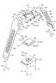
図1は、本実施形態に係る生体情報測定機器の外観を概略的に示す上面図である。図2は、生体情報測定機器の外観を概略的に示す斜視図である。図3は、生体情報測定機器の構造を概略的に示す展開図である。図4は、生体情報測定機器の本体部分の構造を概略的に示す拡大図である。図5は、生体情報測定機器の本体部分の9時側側面を概略的に示す側面図、および端子部分を拡大した拡大図である。図6は、機器本体に接続される第1バンド部を概略的に示す平面図および断面図である。図7は、機器本体に接続される第2バンド部を概略的に示す平面図および断面図である。A biological information measuring device according to this embodiment will be described with reference to FIGS.
FIG. 1 is a top view schematically showing the external appearance of the biological information measuring device according to the present embodiment. FIG. 2 is a perspective view schematically showing the appearance of the biological information measuring device. FIG. 3 is a developed view schematically showing the structure of the biological information measuring device. FIG. 4 is an enlarged view schematically showing the structure of the main body portion of the biological information measuring device. FIG. 5 is a side view schematically showing the 9 o'clock side surface of the main body portion of the biological information measuring device, and an enlarged view of the terminal portion. FIG. 6 is a plan view and a cross-sectional view schematically showing a first band portion connected to the device main body. FIG. 7 is a plan view and a cross-sectional view schematically showing a second band portion connected to the device main body.
[生体情報測定機器1の概略構成]
本実施形態に係る生体情報測定機器1(以下、単に「測定機器1」と称する。)は、生体情報を測定される被検体(例えば人体)の手首等に装着され、脈拍等の生体情報を測定する電子機器である。測定機器1は、図1および図2に示すように腕時計と類似する外観に形成されている。測定機器1は、被検体に密着させて生体情報を測定する機器本体2と、当該機器本体2に取り付けられるバンド3と、を備えている。[Schematic configuration of biological information measuring device 1]
A biological information measuring device 1 according to the present embodiment (hereinafter simply referred to as “measuring device 1”) is attached to a wrist or the like of a subject (for example, a human body) whose biological information is measured, and biological information such as a pulse is transmitted. Electronic equipment to be measured. As shown in FIGS. 1 and 2, the measuring device 1 is formed in an appearance similar to a wristwatch. The measuring device 1 includes a device
[機器本体2の構成]
図2および図3に示す様に測定機器1の機器本体2には、モジュール20と、当該モジュール20が収容されているケース部200と、を備える。モジュール20には、表示部220と、処理部240と、電源部260と、センサー部280と、を備えている。
また、機器本体2には、処理部240に接続されている操作部250と、通信端子266と、を備えている。さらに、機器本体2には、電源部260に接続されている電池262を備え、電池262の充電に用いる充電端子264を備えている。[Configuration of Device Body 2]
As shown in FIGS. 2 and 3, the
In addition, the
ケース部200は、その蓋部210側にモジュール20が収容される凹部200bが形成されている。凹部200bには、モジュール20が収納され、蓋部210が凹部200bを覆うようにして、止めねじ211により固定されている。 The
蓋部210は、その形状を凹部200bと対向する様に凹形状とすることができる。蓋部210を凹形状とすることで、後述する電池262の厚みに応じて凹部200bの深さ(容積)を異ならせることができる。
本実施形態において機器本体2の厚みは、おおよそ14[mm]に形成されている。機器本体2の厚みは、薄い方が被検体に与える圧迫感を緩和することができる。また、被検体の着衣に引っかかることによる測定障害を抑制することができる。機器本体2の厚みは、その強度を保持する観点からおおよそ8[mm]以上とし、被検体の着衣への引っかかりや圧迫感の観点からおおよそ16[mm]以下とすることが好ましい。当該厚みの範囲内で蓋部210を凹形状とすることで電池262の厚みを異ならせることができる。
機器本体2は、上述の通り蓋部210を凹形状とすることで体積も異なる。本実施形態において機器本体2の体積は、当該機器本体2の厚みを14[mm]とした場合は21[cc]となる。なお、機器本体2の体積は、その強度を保持する観点からおおよそ15[cc]以上とし、被検体の着衣への引っかかりや圧迫感の観点からおおよそ50[cc]以下とすることが好ましい。
ケース部200および蓋部210は、その材料は特に限定されない。本実施形態では、その一例としてクラックの発生し難いナイロン系の合成樹脂(プラスチック樹脂)が用いられている。The
In the present embodiment, the thickness of the
As described above, the
The material of the
図2および図3に示すようにケース部200には、蓋部210が設けられた側とは反対側に表示窓200aが設けられている。表示窓200aは、表示部220に表示される生体情報などが視認可能に構成されている。 As shown in FIGS. 2 and 3, the
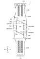
表示窓200aには、第1表示部222に対応する第1表示窓222aと、第2表示部223に対応する第2表示窓223aと、を備える。第1表示窓222aには、第1表示部222が嵌め込まれている(図1および図2参照)。また、第2表示窓223aには、第2表示部223が嵌め込まれている(図1および図2参照)。 The
図4に示すように表示窓200aは、機器本体2からバンド3が延出する方向(第1の方向で図1ないし図3に示すY方向)と交差する方向(第2の方向で図1ないし図3に示すX方向)に延伸する斜辺となる上底(上辺)200eおよび下底(下辺)200fを1組の対辺とする平行四辺形状を有する。
第1表示部222が嵌め込まれた第1表示窓222aは、機器本体2からバンド3が延出する第1の方向と交差する第2の方向に延伸する上底(上辺)222eおよび下底(下辺)222fを備えた矩形状を有する。
第2表示部223が嵌め込まれた第2表示窓223aは、機器本体2からバンド3が延出する第1の方向に延伸する平行線を備えた角丸長方形状を有する。As shown in FIG. 4, the
The
The
ここで表示窓200aは、表示窓200aの上底200eと、第1表示窓222aの上底222eと、が鋭角を成して接するように配設されている。また、表示窓200aは、表示窓200aの下底200fと、第1表示窓222aの下底222fと、が鋭角を成して接するように配設されている。
第2表示窓223aは、表示窓200aの下底200fと第1表示窓222aの下辺222fが鋭角を成して接する内角となる領域に配設されている。Here, the
The
内角となる領域に第2表示部223および第2表示窓223aを設けることで、測定機器1の動作状態などを複数の方法で表示することができる。また、機器本体2の表面積を抑制しつつ、機器本体2を視認した際に第1表示部222(第1表示窓222a)を大きく見せることができる。よって、測定機器1が装着された者に与える圧迫感を抑制することができる。 By providing the
また、表示窓200aには、透明樹脂や透明ガラスなどから形成された表示部カバー体202が嵌め込まれ、この表示部カバー体202により表示部220が保護されている。表示部カバー体202は、表示窓200aに則して平行四辺形状に形成されている。表示部カバー体202は、第1の方向に配設された斜辺となる上底202eおよび下底202fを一組の対辺とした平行四辺形状を有する。 In addition, a display
図1ないし図4に示す様にケース部200には、表示窓200aに沿って枠部205が設けられている。
枠部205は、機器本体2からバンド3が延出する第1の方向と交差する第2の方向で、図1ないし図4に示すX1方向(第1バンド部30が延出する方向を時計で言う12時方向としたときの3時側方向)に枠部205Rと、X2方向(第2バンド部40が延出する方向を時計で言う6時方向としたときの9時側方向)に枠部205Lとが設けられている。
枠部205は、その下底が表示窓200a(表示部カバー体202)と接して配設され、脚となる辺が第2の方向に延設された等脚台形状を有する。また、枠部205の下底となる辺は、表示窓200aの上底200eおよび下底200fとが対となる1組の対辺とは異なる、第1の方向に延伸する1組の対辺よりも長く設けられている。As shown in FIGS. 1 to 4, the
The
The
枠部205Lは、図1ないし図4に示すY2方向に配設されている脚となる辺が、表示窓200aの下底200fの延伸線上に設けられている。よって、枠部205Lは、図1ないし図4に示すY1方向に設けられている脚となる辺が、表示窓200aの上底200eの延伸線上よりもY1側に設けられている。
枠部205Rは、図1ないし図4に示すY1方向に設けられている脚となる辺が、表示窓200aの上底200eの延伸線上に設けられている。よって、枠部205Rは、Y2方向に設けられている脚となる辺が、表示窓200aの下底200fの延伸線上よりもY2側に設けられている。The
In the
枠部205には、表示窓200aが設けられているケース部200の表側に金属を含む膜205aが設けられている。膜205aは、後述する処理部240と電気的に接続されている。膜205aは、測定機器1の外部に設けられた情報処理機器(不図示)と無線通信を行う際のアンテナとして用いることができる。また、膜205aは、後述する操作部250として、いわゆる静電容量型のタッチセンサーとして用いることができる。さらに、膜205aが設けられることで、ケース部200の強度を高めるとともに、ケース部200の肉厚を薄くすることができる。したがって、ケース部200の軽量化を図ることができる。
膜205aを構成する材料は、アンテナとしての性能を発揮できる材料、もしくは静電容量の変化を検知することができる材料であれれば特に限定されることはない。本実施形態の測定機器1においては、ニッケル(Ni)を含む材料を用いている。膜205aにニッケルを用いることで、アンテナとしての性能、ケース部200の強度、およびタッチスイッチとしての性能を確保するとともに、ニッケルの有する光沢色によって測定機器1の意匠性を高めることができる。なお、本実施形態の測定機器1においては、アンテナとしての性能、ケース部200の強度、および意匠性を高めるため、枠部205の側面にも膜205aが設けられている。The
The material constituting the film 205a is not particularly limited as long as it is a material that can exhibit performance as an antenna or a material that can detect a change in capacitance. In the measuring instrument 1 of the present embodiment, a material containing nickel (Ni) is used. By using nickel for the film 205a, the performance as an antenna, the strength of the
図3に示すようにケース部200に収容されたモジュール20には、表示部220が設けられている。表示部220には、第1表示部222と第2表示部223とが設けられている。
第1表示部222には、各表示モードに応じて脈拍数などの生体情報や、現在時刻などの時刻情報などが表示される。また、第1表示部222には、バックライト224が設けられ、第1表示部222を照らすことができる。
第1表示部222は、脈拍等の生体情報(主に数字や、ドットマトリックスで構成されるグラフ)を表示することができれば、表示方式は限定されない。測定機器1においては、その一例として液晶表示装置を用いている。また、バックライト224は、第1表示部222に表示される生体情報を視認できる程度に照明できれば、発光方法や発光色は限定されない。測定機器1においては、緑色に発光するEL(Electro-Luminescence)パネルを用いて第1表示部222の照明をおこなっている。As shown in FIG. 3, the
The
The
第2表示部223には、測定機器1の各動作モード等が第2表示部223の発光色や明滅によって表示される。第2表示部223は、その明滅や表示色によって各動作モードを表示することができれば表示方式は限定されない。測定機器1においては、その一例として発光ダイオードを用いている。 On the
なお、表示部220は、伝達する情報に応じて生体情報等の表示に用いるデバイス(液晶パネルや発光ダイオード)が選択されている。これにより、後述する電池262(電池262に充電されている電力)の消費を抑制することができる。 In the
図3に示す様にケース部200に収容されたモジュール20には、処理部240が設けられている。
処理部240は、マイコン等の半導体装置や記憶装置、通信機能、および電源部260に接続されている電池262の充電制御を実現する電子回路等で構成された基板である。処理部240には、表示部220、操作部250、電源部260、センサー部280、および枠部205に設けられている膜205aが接続されている。処理部240は、センサー部280の駆動や、センサー部280で検出された脈拍に基づく信号を処理し、表示部220における生体情報等の表示処理をすることができる。また、センサー部280で検出された脈拍に基づく信号を解析し、生体情報を検出する間隔(時間間隔)を決定することができる。さらに、処理部240は、検出された生体情報の蓄積をおこない、機器本体2の外部に設けられた情報処理装置との間で通信をおこない蓄積されたデータを出力することができる。As shown in FIG. 3, a
The
図3に示す様にケース部200に収容されたモジュール20には、処理部240に命令を与える操作部250が設けられている。
操作部250は、押下可能な操作ボタン252が設けられている。操作ボタン252を押下することで、例えば脈拍測定データを表示する脈拍測定モード、現在時刻などを表示する時計モード、電池残量の表示モード、脈拍を検出する間隔や電池262の充電容量を設定する設定モード、表示部220のバックライト224点灯モード等の切り替えをおこなうことができる。As shown in FIG. 3, the
The operation unit 250 is provided with an operation button 252 that can be pressed. By pressing the operation button 252, for example, a pulse measurement mode for displaying pulse measurement data, a clock mode for displaying the current time, a display mode for the remaining battery level, a pulse detection interval, and a charge capacity of the battery 262 are set. The setting mode, the
操作部250は、機器本体2からバンド3が延出する第1の方向と交差する第2の方向で、図1ないし図4に示すX1方向(3時側方向)のケース部200の側面に設けられている。操作部250は、操作ボタン252を複数備えることができる。操作部250は、少なくとも1つの操作ボタン252が表示窓200aの上底200eの延伸線上に設けられていることが好ましい。これにより被検体が表示窓200aの上底200eを視認することで、操作ボタン252が設けられている位置を容易に把握することができ、誤操作を防止することができる。
また、複数の操作ボタン252を設け、ほぼ同時に押下することで測定機器1の設定をおこなう設定モードへの切り替えをおこなうことができる。本実施形態の測定機器1には、その一例として、測定機器1には二つの操作ボタン252a,252bが設けられている。被検体による操作部250の操作は、人差し指で操作ボタン252aを押下し、押下に伴う力をケース部200に親指を添えることで操作することができる。
また、薬指で操作ボタン252bを押下し、押下に伴う力をケース部200に親指を添えることで操作することができる。したがって、操作ボタン252a,252bを設ける間隔は、操作する指(例えば親指と人差し指、親指と薬指)が届く範囲で、操作する指が重ならない間隔が好ましい。The operation unit 250 is on the side surface of the
Further, a plurality of operation buttons 252 are provided, and can be switched to a setting mode for setting the measuring device 1 by pressing almost simultaneously. As an example, the measurement device 1 of the present embodiment is provided with two
Further, the operation can be performed by pressing the
図3に示す様にケース部200には、モジュール20を構成し、機器本体2の電源となる電源部260が設けられている。さらに、電源部260には電池262が設けられている。電池262は、充電可能な2次電池として設けられている。電池262は、小型かつ軽量で、蓄電密度の高い電池が好ましい。なお、充電可能な2次電池であれば特に限定されることなく、リチウムイオンポリマー電池やリチウムイオン電池などを用いることができる。本実施形態の測定機器1には、小型かつ軽量で、エネルギー密度の高いリチウムイオン電池(コイン型リチウムイオン電池)を用いている。 As shown in FIG. 3, the
ケース部200には、電池262の充電に用いる充電端子264が設けられている。さらに、ケース部200には、測定機器1で測定および蓄積された生体情報(データ)、および測定設定データ等のデータ通信に用いられる通信端子266が設けられている。 The
図5に示す様にケース部200には、測定機器1の電源となる電源部260に搭載された電池262の充電に用いる充電端子264が設けられている。さらに、ケース部200には、測定機器1で測定および蓄積された生体情報(データ)、および測定設定データ等のデータ通信に用いられる通信端子266が設けられている。
充電端子264および通信端子266は、機器本体2からバンド3が延出する第1の方向と交差する第2の方向で、図1および図2に示すX2方向(9時側方向)のケース部200の側面に設けられている。充電端子264および通信端子266は、その機能を発揮するため一つまたは複数設けられている。本実施形態の測定機器1は、その一例として、それぞれ2つの充電端子264、および2つの通信端子266が設けられている。As shown in FIG. 5, the
The charging
充電端子264および通信端子266は、充電端子264の間に通信端子266が配設されている。換言すると、通信端子266の外側(図5(b)に示すY方向)に充電端子264が配設されている。さらに、充電端子264の外側(通信端子266が設けられている方向と反対方向のY方向)に充電端子264および通信端子266と接続されるコネクター(不図示)の位置決め穴268が設けられている。なお、充電端子264および通信端子266は、凸レンズ状の凸曲面を有し、ケース部200の側面から突出する様に設けられている。また、位置決め穴268は、ケース部200の側面に有底の穴として設けられている。 The charging
図5(b)に示す様に、充電端子264および通信端子266間の間隔d1は、通信端子266間の間隔d2と比して広い。これにより、充電端子264間、および充電端子264と通信端子266との間の短絡を抑制することができる。 As shown in FIG. 5B, the interval d1 between the charging
充電端子264および通信端子266は、導電性を有する材料を用いることができる。本実施形態の測定機器1は、その一例として、ステンレス鋼を充電端子264および通信端子266の材料として用いている。これにより、充電端子264および通信端子266は耐蝕性を備えることができる。また、充電端子264および通信端子266は、ケース部200から突出して設けられるとともに、凸レンズ状の凸曲面を有するため、容易に清掃することができ、充電端子264および通信端子266の腐食を抑制するとともに、導電性を保つことができる。また、充電端子264および通信端子266は、操作部250が設けられている側面と異なる側面に設けられているため、操作ボタン252a,252bを操作する指が触れることを抑制し、皮脂などによる汚れを防ぐことができる。さらに、充電端子264および通信端子266は、耐蝕性の導電材料、たとえば金などで表面をメッキすることで、耐蝕性をさらに向上させることができる。 The charging
図3に戻り、センサー部280について説明する。図3に示す様にケース部200に収容されたモジュール20には、センサーユニット282を備えたセンサー部280が設けられている。
本実施形態の測定機器1は、生体情報の一つとして被検体の脈拍を測定することができる。よって、センサーユニット282は、脈拍を検出する機能を備えている。具体的にはセンサーユニット282は、光センサーであって、センサーケースと、発光素子および受光素子が実装されたセンサー基板とを備えている。センサーユニット282は、LED(Light Emitting Diode)などの発光素子から被検体の手首に向けて光を照射し、手首の血管で反射された光をフォトダイオードなどの受光素子で受光することで被検体の生体情報である脈拍を測定することができる。Returning to FIG. 3, the sensor unit 280 will be described. As shown in FIG. 3, the
The measuring device 1 of this embodiment can measure the pulse of a subject as one piece of biological information. Therefore, the sensor unit 282 has a function of detecting a pulse. Specifically, the sensor unit 282 is an optical sensor, and includes a sensor case and a sensor substrate on which a light emitting element and a light receiving element are mounted. The sensor unit 282 irradiates light from a light emitting element such as an LED (Light Emitting Diode) toward the wrist of the subject, and receives light reflected from the blood vessel of the wrist by a light receiving element such as a photodiode. It is possible to measure the pulse which is the biological information.
蓋部210には、センサー部280が収容されているセンサー土手部212が設けられている。蓋部210から表示部220の表示方向と反対方向に隆起した円盤形状を有するセンサー土手部212に、センサー部280が設けられている。センサー土手部212は、センサー凸部214を備える。
センサー凸部214は、測定機器1を装着した被検体の手首などに押圧(接触)される様に設けられている。センサー凸部214は、蓋部210から延出されている基部214aと、被検体に押圧される先端部214bと、を備える。The
The sensor
このことから、センサー凸部214の基部214aは、遮光性を有する材料で構成されていることが好ましい。また、先端部214bは、発光素子から射出される光を透過させることができる材料で構成されることが好ましい。また、先端部214bは、当該光の乱反射を抑制し、装着時に被検体が痛みを感じない形状が好ましい。
そこで、基部214aは、蓋部210と同じ合成樹脂を用い、遮光性の着色を付して設けられている。また、先端部214bは、透明のガラスや透明のアクリル樹脂を用い、弧形状を有し設けられている。Therefore, it is preferable that the
Therefore, the
[バンド3の構成]
図1ないし図3、および図6を用いてバンド3の構成について説明する。
バンド3は、機器本体2を被検体に装着するために設けられている。バンド3は、図1および図2に示す様に機器本体2の両端に設けられている。バンド3を構成する第1バンド部30は、図3に示す様に機器本体2のラグ203(第1の方向として時計で言えば12時側のラグ)に取付部材32によって取り付けられている。また、バンド3を構成する第2バンド部40は、機器本体2のラグ204(第1の方向として時計で言えば6時側のラグ)に取付部材42によって取り付けられている。[Configuration of band 3]
The configuration of the
The
第1バンド部30には、当該第1バンド部30と第2バンド部40とを連結する連結部310が設けられている。連結部310は、機器本体2側とは反対側の第1バンド部30の端部に設けられている。また、第2バンド部40には、当該第2バンド部40を第1バンド部30に係止するフック部410が設けられている。フック部410は、機器本体2側とは反対側の第1バンド部30の端部に設けられている。 The
以下の説明では、第1バンド部30においては、機器本体2側を「一端側」とし、その反対側で連結部310が設けられた側を「他端側」として説明する。同様に、第2バンド部40においては、機器本体2側を「一端側」とし、その反対でフック部410が設けられた側を「他端側」として説明する。 In the following description, in the
[第1バンド部の構成]
図3および図6に示す第1バンド部30は、ベルト部34と、当該ベルト部34の一端側(機器本体2側で図3および図6(a)に示すY2方向)に設けられた第1接続部(接続部)としてのカバー部320と、他端側(機器本体2の反対側で図3および図4(a)に示すY1方向)に連結部310と、を有する。
ベルト部34は表裏面を有する。以下の説明において、被検体に装着された際に手首と当接する面をベルト部34の裏面34bと称し、その反対面であり装着された際に視認できる面をベルト部34の表面34aと称し、説明する。[Configuration of first band section]
The
The
(機器本体2への取り付け)
第1バンド部30は、ラグ203とカバー部320との間に取付部材32を挟み、カバー部320がラグ203を覆う様に機器本体2に取り付けられている。
カバー部320とラグ203とは、取付部材32に設けられている穴32hと、ラグ203に設けられている「かん穴203h」とに「ばね棒(不図示)」が挿通され、ばね棒の両端がカバー部320に設けられた係止穴320hに係止されることで軸支されている。
ここで、機器本体2と第1バンド部30との接続は、機器本体2の斜辺となる表示部カバー体202の上底202e(表示窓200aの上底200e)と、接続部としてのカバー部320および取付部材32の斜辺となる端部320e,32eと、を対面させた斜め継ぎ(図1参照)で接続されている。
取付部材32およびカバー部320は、ケース部200に設けられている表示窓200aの上底200eに沿って形成されている。また、測定機器1には、第1バンド部30(端部320e,32e)と機器本体2(上底200e)との間に有底の溝290を有する。溝290が設けられていることで、後述するベルト部34が伸縮した際に、ケース部200と取付部材32およびカバー部320が接触し、摩耗することを抑制することができる。(Mounting to the device body 2)
The
The
Here, the connection between the device
The
(ベルト部34)
図6(a)および図6(b)に示すベルト部34は、機器本体2を被検体の手首等に密着して装着するため伸縮性を有する。ベルト部34は、ポリウレタン樹脂またはシリコーン樹脂を含む材料を用いることで、その材料の特性によって、伸縮性および可撓性を備えている。
ベルト部34は、第1バンド部30が機器本体2から延出する方向(第1の方向で図4(a)に示すY1方向)と交差する方向(第2の方向で図6(a)に示すX方向)の断面(図6(a)に示す線分E−E’における断面)において、幅30W方向の中央部分の厚み(図6(b)に示すZ方向)が増して設けられている。ベルト部34は、幅30W方向における中央部分の厚みが増して設けられていることで、伸縮時の強度および屈曲時の強度を確保している。(Belt part 34)
The
The
ベルト部34には、第2バンド部40に設けられたフック部410が係止される子穴330が設けられている。子穴330は、幅30W方向(第2の方向で図6に示すX方向)に並列に、かつベルト部34が延伸する方向(第1の方向で図6に示すY方向)に行を成し整列して設けられている。 The
子穴330は図6(b)に示すように、ベルト部34の表面34a側に設けられた穴331と、ベルト部34の裏面34b側に設けられた穴332が同軸に設けられている。
子穴330は、ベルト部34の幅30W方向(X方向)を長軸(長径)とし、直交する機器本体2から第1バンド部30が延出する方向(Y方向)を短軸(短径)とする楕円形状を有する。子穴330の長軸、および当該長軸と直交する短軸は、穴331と比して穴332の方が長く(大きく)設けられている。As shown in FIG. 6B, the
The
(連結部310)
連結部310は、ベルト部34の他端側(図6(a)に示すY1方向)に設けられている。
ベルト部34の他端側には、子穴330が設けられている部分と比してベルト部34の厚みを増した肉厚部345を有している。連結部310は、当該ベルト部34の厚みを増した肉厚部345に設けられている。連結部310には、第2バンド部40を挿通する挿通穴312と、第2バンド部40に設けられている子穴430(図7参照)に挿通される突棒314が設けられている。(Connecting part 310)
The connecting
On the other end side of the
連結部310においてバンド挿通穴312は、機器本体2から第1バンド部30が延出する方向(図6(a)に示すY1方向)と交差する方向(図6(a)に示すY2方向)の幅312Wは、第2バンド部40の幅40W(図7参照)より広く設けられている。
より詳しくは、後述する突棒314が係止される係止穴312hが設けられた一辺側(図6(a)に示すY2側)の幅より、後述する凹部312cが設けられている一辺側(図6(a)に示すY1側)の幅が広く設けられている。
バンド挿通穴312は、Y1側の幅が広く設けられていることで第2バンド部40を容易に挿通することができる。また、第2バンド部40を幅が広く設けられているY1側のバンド挿通穴312の縁に接触させてY2側に引っぱり、第2バンド部40を伸長することで機器本体2の手首への密着性を高め、第2バンド部40(ベルト部44)の復元力による締め付けを調整することができる。In the connecting
More specifically, the width of one side (Y2 side shown in FIG. 6 (a)) where a
The
突棒314は、バンド挿通穴312の内縁でY2側の一辺に設けられている係止穴312hと、当該突棒314に設けられている穴(不図示)と、を挿通する「ばね棒(不図示)」によってベルト部34に軸支されている。突棒314は、バンド挿通穴312の内縁でY1側の一辺に設けられている凹部312cに、その一部が嵌合されることでベルト部34に係止されている。
突棒314は、バンド挿通穴312の内縁でY2側の一辺側から2つの棒部3141,3142がY1方向に延設されている。また、突棒314は、棒部3141,3142が延伸するY1方向と交差するベルト部34の幅30W方向(図6(a)に示すX方向)に連絡棒3143が設けられている。突棒314を構成する棒部3141,3142の断面形状は、扁平形を有する。突棒314は扁平形を有することで、子穴430に挿通された際の接触面積を大きくすることができ、子穴430が伸長されることを抑制するとともに、本実施形態のバンド3によって被検体に装着された測定機器1のズレを抑制することができる。The projecting
The protruding
突棒314を構成する材料は特に限定されることなく、ベルト部34,44の復元力に耐えうる材料であれば良い。本実施形態において突棒314は、その一例としてステンレス鋼が用いられている。突棒314は、ステンレス鋼を用いることでベルト部34,44の復元力に対する靱性、および耐蝕性を備えることができる。また、突棒314は、棒部3141,3142が延伸する方向(Y方向)に沿ってヘアライン加工が施されている。ヘアライン加工を施すことで、突棒314の視認性を高め、子穴430への挿入を補助することができる。 The material constituting the protruding
本実施形態のバンド3は、バンド挿通穴312に第2バンド部40が挿通され、突棒314が第2バンド部40に設けられている子穴430に挿通されることで、第1バンド部30と第2バンド部40とが連結される。
ここで、バンド3は、被検体の生体情報を測定するために、機器本体2を被検体に密着させ、その装着位置がずれないことが求められる。
そのため、第2バンド部40には子穴430が並列に設けられ、突棒314が挿通されることで装着位置のズレを抑制している(図7参照)。連結部310は、子穴430に対応して突棒314を構成する棒部3141,3142が並列に設けられ、その間隔を連絡棒3143で保っている。これにより、突棒314はH形状を有し、棒部3141,3142の間隔を連絡棒3143によって保ちつつ、並列に設けられた子穴430に突棒314を容易に挿通することができる。In the
Here, in order to measure the biological information of the subject, the
For this reason, the
(カバー部320)
第1接続部としてのカバー部320は、ベルト部34の一端側(図6(a)に示すY2方向)に設けられている。カバー部320には、係止穴320hが設けられている。
カバー部320は、取付部材32を介して第1バンド部30を機器本体2に接続するために設けられている。カバー部320の幅320Wと、機器本体2の幅2Wと、は略等しい幅を有している(図1参照)。
より詳しくは、機器本体2から第1バンド部30が延出する方向(図1ないし図6に示すY1方向)と交差する方向(図1ないし図3、または図6に示すX方向)において、カバー部320の幅320Wと、機器本体2の幅2Wと、が略等しい幅を有している。また、カバー部320は、平行四辺形状に形成されている表示窓200aの上底200eに沿って斜辺となる端部320eを備えた形状に形成されている(図3参照)。これにより、機器本体2と第1バンド部30とが視覚的に一体に形成されているように視認することができ、装着による圧迫感を緩和することができる。また、幅方向(X方向)において第1バンド部30から機器本体2が突出していないため、装着時に被検体の衣服が機器本体2に引っかかることを抑制することができる。(Cover part 320)
The
The
More specifically, in a direction (X direction shown in FIGS. 1 to 3 or 6) intersecting with a direction (Y1 direction shown in FIGS. 1 to 6) in which the
[第2バンド部の構成]
図3および図7に示す第2バンド部40は、ベルト部44と、当該ベルト部44の一端側(機器本体2側で図3および図7(a)に示すY1方向)に設けられた第2接続部(接続部)としてのカバー部420と、他端側(機器本体2の反対側で図3および図7(a)に示すY2方向)にフック部410と、を有する。なお、図7(a)においては、フック部410が設けられる凹部410cおよび子穴440の図示を簡略化している。
ベルト部44は表裏面を有し、以下の説明において、被検体に装着された際に手首と当接する面をベルト部44の裏面44bと称し、その反対面で装着された際に視認できる面をベルト部44の表面44aと称し、説明する。[Configuration of second band section]
The
The
(機器本体2への取り付け)
第2バンド部40は、ラグ204とカバー部320との間に取付部材42を挟み、カバー部420がラグ204を覆う様に機器本体2に取り付けられている。
カバー部420とラグ204とは、取付部材42に設けられている穴42hと、ラグ204に設けられている「かん穴204h」とに「ばね棒(不図示)」が挿通され、ばね棒の両端がカバー部420に設けられた係止穴420hに係止されることで軸支されている。
ここで、機器本体2と第2バンド部40との接続は、機器本体2の斜辺となる表示部カバー体202の下底202f(表示窓200aの下底200f)と、接続部としてのカバー部420および取付部材42の斜辺となる端部420f,42fとを対面させた斜め継ぎ(図1参照)で接続されている。
取付部材42およびカバー部420は、ケース部200に設けられている表示窓200aの下底200fに沿って形成されている。また、測定機器1には、第2バンド部40(端部420f,42f)と機器本体2(下底200f)との間に有底の溝290が設けられている。溝290が設けられていることで、後述するベルト部44が伸縮した際に、ケース部200と取付部材42およびカバー部420が接触し、摩耗することを抑制することができる。(Mounting to the device body 2)
The
The
Here, the connection between the device
The
(ベルト部44)
図7(a)および図7(b)に示すベルト部44は、機器本体2を被検体の手首等に密着して装着するため伸縮性を有する。ベルト部44は、ポリウレタン樹脂またはシリコーン樹脂を含む材料を用いることで、その材料の有する特性によって、伸縮性および可撓性を有している。
ベルト部44は、第2バンド部40が機器本体2から延出する方向(第1の方向で図7(a)に示すY2方向)と交差する方向(第2の方向で図7(a)に示すX方向)の断面(図7(a)に示す線分F−F’における断面)において、幅40W方向の中央部分の厚み(図7(b)に示すZ方向)が増して設けられている。ベルト部44は、幅40w方向における中央部分の厚みが増して設けられていることで、伸縮時の強度および屈曲時の強度を確保している。(Belt part 44)
The
The
ベルト部44には、第1バンド部30に設けられた突棒314が挿通される子穴430が設けられている。子穴430は、幅40W方向(第2の方向で図7に示すX方向)に並列に、かつベルト部44が延伸する方向(第1の方向で図7に示すY方向)に行を成し整列して設けられている。 The
子穴430は図7(b)に示すように、ベルト部44の表面44a側に設けられた穴431と、ベルト部44の裏面44b側に設けられた穴432が同軸に設けられている。
子穴430は図7(b)に示すように、ベルト部44の幅40W方向(X方向)を長軸(長径)とし、直交する機器本体2から第1バンド部30が延出する方向(Y方向)を短軸(短径)とする楕円形状を有する。子穴430の長軸および直交する短軸は、穴431と比して穴432の方が長く(大きく)設けられている。
なお、穴431,432の有する楕円形状は、前述した連結部310に設けられている突棒314の断面形状に即したものであり、その形状に合わせて適宜変更しても良い。穴431,432は、楕円形状を有することで容易に変形することができ、突棒314の挿通が簡便にできる。なお、変形後の復元力にも優れている。As shown in FIG. 7B, the
As shown in FIG. 7 (b), the
The oval shape of the holes 431 and 432 is in accordance with the cross-sectional shape of the protruding
ベルト部44は図7(a)に示すように、並列に設けられた子穴430の間に符号mが付されている。符号mは、機器本体2から第2バンド部40が延出する方向(図7(a)に示すY2方向)に向かって順を成して付されている。符号mは、例えば数字の場合、機器本体2側(図7(a)に示すY1側)から順に「1,2,3,…17」と付されている。また、アルファベットの場合、機器本体2側から順に「a,b,c…」と付すことができる。アルファベットを用いた場合には、数字を用いた場合と比して、同じ文字の大きさで多くの子穴430の順列を示すことができる。すなわち、アルファベット25文字に相当する数の子穴430の順列を1文字で文字の大きさを保って示すことができる。符号mの字体は、子穴430の順番を示すことができれば特に限定されない。
ベルト部44に符号mが付されていることで、測定機器1を手首等に繰り返し装着する際に、第1バンド部30と第2バンド部40とを連結させるため突棒314を挿通する最適な位置を容易に識別することができ、装着毎に最適な突棒314を挿通する子穴430の位置を模索することなく測定機器1を装着することができる。また、符号mは、並列に設けられた子穴430の間に付されているため、新たにスペース(領域)を設けることなく第2バンド部40に付すことができる。As shown in FIG. 7A, the
The
また、ベルト部44には図7(a)に示すように、後述するフック部410の基部412が嵌合される凹部400cと、基部412から延出されたピン414が挿入される子穴440と、が設けられている。
凹部400cは、ベルト部表面44aに基部412の外周縁に沿った凹形状を有する。また、凹部400cの深さ400dは、基部412の厚み412tと略同じ寸法として設けられている。Further, as shown in FIG. 7A, the
The concave portion 400c has a concave shape along the outer peripheral edge of the
子穴440は図7(a)に示すように、幅40W方向(X方向)に並列に、基部412から延出されているピン414と同軸に設けられている。子穴440は、ベルト部表面44a側で凹部400cの底部に設けられた穴(不図示)と、ベルト部裏面44bに設けられた穴(不図示)と、が同軸に設けられている。 As shown in FIG. 7A, the child hole 440 is provided coaxially with the
(フック部410)
図1ないし図3、または図7に示すようにフック部410は、ベルト部44の他端側(図1ないし図3、または図7に示すY2方向)に設けられている。
図7(c)に示すようにフック部410には、基部412と、基部412から延出しているピン414が設けられている。ピン414は、第1軸部416と、第2軸部418と、を含み構成されている。フック部410は、第1バンド部30に設けられている子穴330にピン414を挿入することで、連結部310に挿通された第2バンド部40を第1バンド部30に係止する部材である。(Hook part 410)
As shown in FIG. 1 to FIG. 3 or FIG. 7, the
As shown in FIG. 7C, the
フック部410には、ベルト部34の幅30Wの方向(図1ないし図3に示すX方向)に並列に設けられている子穴330の間隔に合わせて複数のピン414が設けられている。
ピン414は、第2バンド部40に設けられた子穴440、および第1バンド部30に設けられた楕円形状を有する子穴330に挿入されるため、断面形状は楕円形状を有する。ピン414は、ベルト部34の幅30W方向(ベルト部44の幅40W方向)を長軸(長径)とし、直交する機器本体2から第2バンド部40が延出する方向(Y方向)を短軸(短径)とする楕円形状に形成されている。The
Since the
フック部410には、基部412からピン414を構成する第1軸部416が突出する様に設けられている。また、第1軸部416の一端(図7に示すZ2方向で、第1軸部416が延出する基部412とは反対側の一端)には、第2軸部418が設けられている。 The
第1軸部416には、第1頭部417が設けられている。第1頭部417は、第1軸部416が延出する基部412とは反対側(図7に示すZ2方向)に設けられている。第1頭部417には、第2軸部418が設けられる側(図7に示すZ2方向)の外周縁に曲面417rを有する。
第1頭部417の径は、第1軸部416の径と比べて大きく設けられている。また、第1頭部417の径は、穴441の径と比べて大きく、穴442の径と比べて小さく設けられている。A
The diameter of the
また、第2軸部418には、第2頭部419が設けられている。第2頭部419は、第2軸部418が延出する第1軸部416とは反対側(図7に示すZ2方向)に設けられている。第2頭部419は、第1軸部416が設けられている側とは反対側(図7に示すZ2方向)の外周縁に曲面419rを有する。
第2頭部419の径は、第2軸部418の径と比べて大きく設けられている。
また、第1頭部417の径は、先端部318が挿入される子穴330に設けられた穴331の径と比べて大きく、穴332の径と比べて小さく設けられている。The
The diameter of the
The diameter of the
ここで基部412の厚み(ピン414が延出する方向で、図7に示すZ方向の厚み)と、ピン414の長さ(ピン414が延出する方向で、図7に示すZ方向の長さ)は、子穴440および穴331(子穴330)の深さによって決定される。
本実施形態の基部412の厚み412tは、凹部400cの深さと略等しい。第1軸部416の軸部分の長さ416Lは、穴441の深さ(長さ)と略等しい。第1軸部416の第1頭部417の長さ(厚み)417Lは、穴442の深さ(長さ)と略等しい。第2軸部418の軸部分の長さ418Lは、穴331の深さ(長さ)と略等しい。第2軸部418の第2頭部419の長さ(厚み)419Lは、穴332の深さ(長さ)と略等しい。Here, the thickness of the base 412 (in the direction in which the
The
フック部410は、ベルト部44の表面44aに設けられている凹部410cにフックベース412が嵌合される。さらに、フック部410は、ベルト部44の幅40W方向に並列に設けられた子穴440に、フックベース412から延出するピン414が挿入されることでベルト部44に設けられる。フック部410は、ベルト部44に設けられた際に、第2軸部418がベルト部44の裏面44bから突出する様に設けられている。第2軸部418は、ベルト部44から突出されていることで、第1バンド部30(ベルト部34)に設けられている子穴330に挿入することができる。 In the
これにより、穴441に挿通された第1軸部416は、穴441に第1頭部417が引っかかり、ベルト部44からフック部410が脱離することを抑制することができる。
より詳しくは、第1頭部417に設けられた曲面417rによって、第1軸部416を穴441に挿通する際に生じる接触抵抗を低減することができる。なお、基部412側の第1頭部417には、曲面417rが設けられていないため、第1軸部416を穴441から引き抜く際は挿通時より大きな力が必要となる。よって、フック部410がベルト部44から脱離することを抑制することができる。Thus, the
More specifically, the contact resistance generated when the
また、子穴330に挿入された第2軸部418は、第2頭部419が第1バンド部30に設けられている穴331に引っかかり、第1バンド部30に第2バンド部40を係止することができる。また、第1バンド部30に係止された第2バンド部40が脱離することを抑制することができる。
より詳しくは、第2頭部419に設けられた曲面419rによって、第2軸部418を穴331に挿入する際に生じる接触抵抗を低減することができる。なお、第1軸部416側の第2頭部419には、曲面419rが設けられていないため、第2軸部418を穴331から引き抜く際は挿入時より大きな力が必要となる。よって、第1バンド部30に係止された第2バンド部40が脱離することを抑制することができる。In addition, the
More specifically, the contact resistance generated when the
(カバー部420)
第2接続部としてのカバー部420は、ベルト部44の一端側(図7(a)に示すY1方向)に設けられている。カバー部420には、係止穴420hが設けられている。
カバー部420は、取付部材42を介して第2バンド部40を機器本体2に接続するために設けられている。カバー部420の幅420Wと、機器本体2の幅2Wと、は略等しい幅を有している(図1参照)。
より詳しくは、機器本体2から第2バンド部40が延出する方向(図1ないし図3または図6に示すY1方向)と交差する方向(図1ないし図3、または図7に示すX方向)において、カバー部420の幅420Wと、機器本体2の幅2Wと、が略等しい幅を有している。また、カバー部420は、平行四辺形状に形成されている表示窓200aの下底200fに沿って斜辺となる端部420fを備えた形状に形成されている(図3参照)。これにより、機器本体2と第2バンド部40とが視覚的に一体に形成されているように視認することができ、装着による圧迫感を緩和することができる。また、幅方向(X方向)において第2バンド部40から機器本体2が突出していないため、装着時に装着者の衣服が機器本体2に引っかかることを抑制することができる。(Cover part 420)
The
The
More specifically, the direction (the X direction shown in FIG. 1 to FIG. 3 or FIG. 7) that intersects the direction (the Y1 direction shown in FIG. 1 to FIG. 3 or FIG. 6) in which the
(機器本体2の動作)
機器本体2は、センサー部280によって被検体の生体情報の一つでる脈拍を検出することができる。生体情報(脈拍)の検出は、センサー部280に設けられているセンサーユニット282を間欠的に機能させることでおこなうことができる。
センサーユニット282で検出された生体情報は、処理部240に伝送され、各種情報処理がおこなわれる。情報処理がおこなわれた生体情報は、表示部220への表示や、処理部240に備えられた記憶装置に記録される。記録された生体情報は、機器本体2と測定機器1を構成する受信装置(不図示)との間を無線通信、もしくは通信端子266を介した有線通信によって機器本体2の外部に送信することができる。(Operation of device body 2)
The
The biological information detected by the sensor unit 282 is transmitted to the
ここで、脈拍などの生体情報は、被検体の活動によって、その値と、経時に伴う値の変化が大きく異なる。例えば、脈拍は、被検体が就寝している時は経時に伴う値の変化が少ない。他方、被検体が運動(歩行やジョギングなど)している時は経時に伴う値の変化が大きい。 Here, the value of the biological information such as a pulse greatly varies depending on the activity of the subject and the value with time. For example, when the subject is sleeping, the pulse changes little with time. On the other hand, when the subject is exercising (walking, jogging, etc.), the value changes with time.
生体情報として脈拍を測定する場合、経時(時間経過)にともなう脈拍の変化を捕捉することが肝要である。したがって、経時にともなう脈拍の変化が少ない時に連続、もしくは短い周期で脈拍を検出しても生体情報として利用価値が低い。また、経時にともなう脈拍の変化の大きい時に脈拍を間欠的に検出しても脈拍の変化を捉えることができなく、有用な生体情報を得られない。
連続して生体情報の測定をおこなえばこれらの課題は解消するが、機器本体2に搭載されている電池262を早く消耗させ、生体情報を測定することができる期間が短くなるという課題が新たに生じる。When measuring a pulse as biological information, it is important to capture changes in the pulse with the passage of time (elapsed time). Therefore, even if the pulse is detected continuously or with a short period when the change of the pulse with time is small, the utility value is low as biometric information. Further, even if the pulse is detected intermittently when the change of the pulse with time is large, the change of the pulse cannot be captured, and useful biological information cannot be obtained.
If the biological information is continuously measured, these problems are solved. However, a new problem is that the battery 262 mounted on the
そこで、本実施形態の測定機器1は、検出された脈拍に基づき、機器本体2における脈拍を検出する間隔を可変できる。すなわち、生体情報の変化が少なくなった場合には検出間隔を延ばし、生体情報の変化が大きくなった場合には検出間隔を短くする。
具体的には、センサー部280で検出された脈拍を処理部240で解析し、被検体の脈拍が所定値(例えば、安静時の脈拍値)を下廻り、所定時間において脈拍の変動が所定の変化率の範囲であればセンサー部280による脈拍の検出間隔を長くする。また、センサー部280で検出された脈拍を処理部240で解析し、脈拍が所定値を上廻り、所定時間において脈拍が所定の変化率の範囲を超えればセンサー部280による脈拍の検出間隔を短くする。
なお、測定機器1に検出間隔は、単にセンサー部280の動作間隔だけでなく、連続して生体情報を測定するモード、表示部220に時刻を表示するモード、表示部220の表示もおこなわないモードなどを組み合わせた態様を含むものである。Therefore, the measuring device 1 of the present embodiment can vary the interval for detecting the pulse in the
Specifically, the pulse detected by the sensor unit 280 is analyzed by the
Note that the detection interval in the measuring device 1 is not only the operation interval of the sensor unit 280, but also a mode in which biological information is continuously measured, a mode in which time is displayed on the
本実施形態の測定機器1は、被検体の生体情報を処理部240で解析することで、例えば1日(24時間)に必要な生体情報の検出間隔(時間に応じた検出回数)を得ることができる。また、例えば日中の活動帯や、夜間の就寝帯など、活動に応じた生体情報の検出間隔(時間に応じた検出回数)を得ることができる。
なお、脈拍の検出間隔、および検出間隔の変更を判断する所定値および変化率は、測定機器1が装着される被検体によって適正値が異なる。よって、被検体に応じて任意の値に操作部250を用いて設定することができる。
したがって、脈拍(生体情報)の変化が少ない時にセンサー部280の検出動作を休止させることで電池262の消費を抑制し、1回の充電による生体情報の測定期間を延伸させることができる。The measuring device 1 of this embodiment obtains the detection interval (the number of detections according to time) of biological information necessary for one day (24 hours), for example, by analyzing the biological information of the subject with the
Note that the pulse detection interval and the predetermined value and rate of change for determining the change of the detection interval vary depending on the subject to which the measuring device 1 is attached. Therefore, an arbitrary value can be set using the operation unit 250 according to the subject.
Therefore, the consumption of the battery 262 can be suppressed by pausing the detection operation of the sensor unit 280 when there is little change in the pulse (biological information), and the measurement period of the biological information by one charge can be extended.
本実施形態の測定機器1における消費電力(消費電流)について説明する。
測定機器1において、連続して(たとえば15Hzのサンプリングレートで)生体情報としての脈拍を検出する場合(以下、「検出モード」と称す。)、おおよそ1400[μA・H]の消費電流となる。また、測定機器1において、生体情報の測定を休止して時刻等を表示する場合(操作部250による一定の操作、およびバックライト224の点灯等を含む。以下「時刻表示モード」と称する。)、おおよそ460[μA・H]の消費電流となる。さらに、測定機器1において、生体情報の測定を休止して被検体に装着されない場合(操作部250による操作などがない場合。以下「待機モード」と称する。)は、おおよそ350[μA・H]の消費電流となる。さらに、表示部220における時刻等の表示をおこなわない場合(以下、「非表示モード」と称する。)は、おおよそ14[μA・H]の消費電流となる。The power consumption (current consumption) in the measuring device 1 of this embodiment will be described.
When the measuring device 1 continuously detects a pulse as biological information (hereinafter, referred to as “detection mode”) (for example, at a sampling rate of 15 Hz), the current consumption is approximately 1400 [μA · H]. Further, in the measuring device 1, when the measurement of the biological information is suspended and the time is displayed (including a certain operation by the operation unit 250, lighting of the
ここで、搭載される電池262(コイン型リチウムイオン電池、型式PD2032を例示する。)の容量がTyp45[mA・H](公称75[mA・H])の場合、検出モードを連続した場合には、おおよそ32時間継続することが可能である。また、時刻表示モードを連続した場合には、おおよそ98時間継続することが可能である。さらに、待機モードを連続した場合には、おおよそ129時間継続することが可能である。さらに、非表示モードを連続した場合には、おおよそ3214時間継続することができる。 Here, when the capacity of the battery 262 (a coin type lithium ion battery, model PD 2032 is exemplified) is Typ 45 [mA · H] (nominal 75 [mA · H]), the detection mode is continuous. Can last approximately 32 hours. When the time display mode is continued, it can be continued for approximately 98 hours. Furthermore, when the standby mode is continued, it can be continued for approximately 129 hours. Furthermore, when the non-display mode is continued, it can be continued for approximately 3214 hours.
本実施形態の測定機器1は、前述した通り検出された生体情報である脈拍に基づき脈拍を検出する検出間隔(前述した各モードの組み合わせを含む。)を可変させることができる。
例えば、測定機器1の動作は、被検体が運動をおこなっている場合、検出モードで動作する。また、測定機器1は、被検体が軽作業等をおこなっている場合、検出モードと時刻表示モードとの比率を5:5として動作する。さらに、測定機器1は、被検体が就寝など安静状態の時は、検出モードと待機モードとの比率を2:8として動作する。ここで、運動をおこなっている時間を8時間、軽作業をおこなっている時間を8時間、安静状態の時間を8時間であったとする。
上述の被検体の活動にともなう生体情報を測定するために必要な電力(エネルギー)は、運動をおこなっている8時間で11600[μA・H]、軽作業をおこなっている8時間で9600[μA・H]、安静状態の8時間で8484[μA・H]、合計29684[μA・H]の消費電流となる。したがって、1回の充電で24時間以上連続して被検体の生体情報の測定をおこなうことができる。
なお、測定機器1は、24時間以上連続して生体情報の測定が可能となれば、被検体の1日の活動(例えば、日中の活動時と夜間の睡眠時の1サイクル)における生体情報を得ることができる。また、36時間以上連続して生体情報の測定が可能となれば、被検体の2日分の活動時(例えば、日中の活動時と、夜間の睡眠時と、翌日の活動時)における生体情報を得ることができる。さらに、48時間以上連続して生体情報の測定が可能となれば、被検体の2日間の活動における生体情報を得ることができる。The measuring device 1 of the present embodiment can vary the detection interval (including combinations of the modes described above) for detecting the pulse based on the pulse that is the biological information detected as described above.
For example, the measurement device 1 operates in the detection mode when the subject is exercising. Further, when the subject is performing a light work or the like, the measuring device 1 operates with a ratio of the detection mode to the time display mode of 5: 5. Further, when the subject is in a resting state such as sleeping, the measuring device 1 operates with a ratio of the detection mode to the standby mode of 2: 8. Here, it is assumed that the exercise time is 8 hours, the light work time is 8 hours, and the rest time is 8 hours.
The electric power (energy) required to measure the biological information associated with the activity of the subject is 11600 [μA · H] in 8 hours of exercise and 9600 [μA in 8 hours of light work. H], 8484 [μA · H] in 8 hours in a resting state, resulting in a total current consumption of 29684 [μA · H]. Therefore, the biological information of the subject can be measured continuously for 24 hours or more with one charge.
In addition, if the measuring device 1 can measure biological information continuously for 24 hours or more, the biological information in the subject's daily activity (for example, one cycle during daytime activity and nighttime sleep). Can be obtained. If biological information can be measured continuously for 36 hours or more, the living body during the activity of the subject for two days (for example, during the daytime activity, during the nighttime sleep, and during the next day activity). Information can be obtained. Furthermore, if it is possible to measure biological information continuously for 48 hours or more, it is possible to obtain biological information on the activity of the subject for two days.
前述した測定機器1の動作比率は、被検体から得られた生体情報に基づき適宜変更しても良い。測定機器1の動作比率を変更することで、電池262の容量や個数を変更することなく連続して生体情報の測定をおこなうことができる時間を延ばすことができる。
なお、測定機器1の動作比率を変更することなく、電池262の容量や個数を変更して連続して生体情報の測定をおこなうことができる時間を延ばすことができる。電池262の増量は、前述した機器本体2の厚みが16[mm]を超えない範囲でおこなうことができる。The operation ratio of the measurement device 1 described above may be changed as appropriate based on biological information obtained from the subject. By changing the operation ratio of the measuring device 1, it is possible to extend the time during which biometric information can be continuously measured without changing the capacity or number of the batteries 262.
In addition, the time which can measure biometric information continuously can be extended by changing the capacity | capacitance and number of the batteries 262, without changing the operation | movement ratio of the measuring device 1. FIG. The increase of the battery 262 can be performed in a range where the thickness of the device
また、測定機器1は、電池262の残容量に応じて生体情報の検出間隔を伸長(動作比率を変更)させることができる。
予め設定した測定期間における生体情報の測定が電池262の容量により達成することができないと処理部240が判断したときは、かかる電池262の容量に応じてセンサー部280を用いて脈拍を検出する間隔を伸長させることができる。これにより、被検体の行動が予め設定した内容と異なっても、予め設定した測定期間における生体情報の欠測を防止することができる。したがって、長時間に渡り連続して生体情報の測定をおこなうことで被検体の生活様式を客観的に分析することができる。In addition, the measuring device 1 can extend the biometric information detection interval (change the operation ratio) according to the remaining capacity of the battery 262.
When the
(機器本体2の充電)
本実施形態の測定機器1は、機器本体2をバンド3によって被検体に装着することで生体情報を測定することができる。そのため、機器本体2は駆動源として充電可能な電池262(2次電池)が搭載されている。電池262の充電は、機器本体2が被検体に装着されていない状態でおこなう。具体的には、ケース部200の側面に設けられた充電端子288にコネクター(不図示)を接続して充電用の電力を供給する。また、電池262の充電の制御は、処理部240に設けられた充電制御回路でおこなうことができる。(Charging the device body 2)
The measuring device 1 of the present embodiment can measure biological information by attaching the device
ここで、電池262の充電量および電池262の容量は、生体情報の検出回数(測定期間)に応じた電力(エネルギー)量であることが求められる。
電池262の充電は、例えば、24時間(1日間)生体情報の測定をおこなう場合、24時間に必要な検出間隔(検出回数)に応じた電力の充電をおこなう。24時間連続して生体情報の測定をおこなった場合の消費電流は、おおよそ33600[μA・H]となる(1時間あたり、おおよそ1400[μA・H])。したがって、電池262の充電量は、24時間連続して生体情報の測定をおこなうことができる33600[μA・H]以上とする。また、例えば、日中の活動時間帯のみ生体情報の測定をおこなう場合は、日中の活動時間帯に必要な検出間隔(検出回数)に応じた電力量の充電をおこなう。日中8時間連続して生体情報の測定をおこなった場合の消費電流は、おおよそ11200[μA・H]となる(1時間あたり、おおよそ1400[μA・H])。したがって、電池262の充電量は、8時間連続して生体情報の測定をおこなうことができる11200[μA・H]以上とする。また、電池262の充電量は、処理部240で解析された生体情報に基づき制御することができる。すなわち、処理部240で解析された被検体の活動に応じた検出間隔で測定可能な充電量とすることができる。
これにより、生体情報を測定する期間(時間)に必要な電池262の充電量とすることができる。したがって、充電時間の短縮化、および電池262の劣化を抑制することができる。Here, the amount of charge of the battery 262 and the capacity of the battery 262 are required to be the amount of electric power (energy) corresponding to the number of times biometric information is detected (measurement period).
For example, when the biological information is measured for 24 hours (one day), the battery 262 is charged with power corresponding to the detection interval (number of detections) required for 24 hours. When biometric information is measured continuously for 24 hours, the current consumption is approximately 33600 [μA · H] (approximately 1400 [μA · H] per hour). Therefore, the amount of charge of the battery 262 is set to 33600 [μA · H] or more, which can measure biometric information continuously for 24 hours. Further, for example, when measuring biological information only during the daytime activity time zone, charging is performed with the amount of power corresponding to the detection interval (number of detections) required during the daytime activity time zone. The current consumption when biometric information is measured continuously for 8 hours during the day is approximately 11200 [μA · H] (approximately 1400 [μA · H] per hour). Therefore, the charge amount of the battery 262 is set to 11200 [μA · H] or more that can measure biometric information continuously for 8 hours. Further, the charge amount of the battery 262 can be controlled based on the biological information analyzed by the
Thereby, it can be set as the charge amount of the battery 262 required in the period (time) which measures biometric information. Therefore, shortening of charging time and deterioration of the battery 262 can be suppressed.
電池262の容量は、生体情報の測定時間および検出間隔によって選定される。例えば、活動時間帯の生体情報の測定を主とする場合には、その活動時間帯に必要な検出間隔(検出回数)に応じた容量の電池262を選択することができる。例えば、就寝時間帯の生体情報の測定を主とする場合には、その就寝時間帯に必要な検出間隔(検出回数)に応じた容量の電池262を選択することができる。すなわち、生体情報の測定を欲する被検体の状態(時間帯)に応じて電池262の容量を異ならせることで、機器本体2の軽量化を図ることができる。さらに、電池262の電気的な容量および物理的な容積に応じて機器本体2のケース部200の大きさを異ならせることで、機器本体2の小型化を図ることができる。 The capacity of the battery 262 is selected according to the measurement time and detection interval of biological information. For example, when measuring mainly biological information in an activity time zone, a battery 262 having a capacity corresponding to a detection interval (number of detections) required in the activity time zone can be selected. For example, in the case of mainly measuring biological information in the bedtime, a battery 262 having a capacity corresponding to the detection interval (number of detections) necessary for the bedtime can be selected. That is, it is possible to reduce the weight of the
上述した実施形態によれば、以下の効果を得ることができる。
このような測定機器1によれば、バンド3によって被検体に装着された機器本体2に設けられているセンサー部280によって、当該被検体の生体情報を測定することができる。センサー部280による生体情報の検出は、処理部240で制御されることで間欠的におこなわれる。したがって、センサー部280や処理部240に供給される電源は間欠的に消費される。よって、消費電力および電池262の消費を抑制し、測定可能な時間を長くすることができる測定機器1を実現することができる。According to the embodiment described above, the following effects can be obtained.
According to such a measuring device 1, the biological information of the subject can be measured by the sensor unit 280 provided in the device
1…測定機器、2…機器本体、2W…機器本体の幅、3…バンド部、20…モジュール、30…第1バンド部、32…取付部材、34…ベルト部、40…第2バンド部、42…取付部材、44…ベルト部、200…ケース部、200a…表示窓、200b…凹部、202…表示部カバー、203,204…ラグ、210…蓋部、212…センサー土手部、214…センサー凸部、214a…基部、214b…先端部、220…表示部、224…バックライト、240…処理部、250…操作部、252…操作ボタン、252a…操作ボタン、252b…操作ボタン、260…電源部、262…電池、264…充電端子、266…通信端子、280…センサー部、282…センサーユニット、310…連結部、312…バンド挿通穴、314…突棒、320…カバー部、320W…第1バンド部の幅、330…穴部、345…肉厚部、410…フック部、420…カバー部、420W…第2バンド部の幅、430,440…穴部。 DESCRIPTION OF SYMBOLS 1 ... Measuring apparatus, 2 ... Apparatus main body, 2W ... Width of apparatus main body, 3 ... Band part, 20 ... Module, 30 ... 1st band part, 32 ... Mounting member, 34 ... Belt part, 40 ... 2nd band part, 42 ... Mounting member, 44 ... Belt part, 200 ... Case part, 200a ... Display window, 200b ... Recessed part, 202 ... Display part cover, 203, 204 ... Lug, 210 ... Cover part, 212 ... Sensor bank part, 214 ... Sensor Convex part, 214a ... base part, 214b ... tip part, 220 ... display part, 224 ... back light, 240 ... processing part, 250 ... operation part, 252 ... operation button, 252a ... operation button, 252b ... operation button, 260 ... power supply Part, 262 ... battery, 264 ... charge terminal, 266 ... communication terminal, 280 ... sensor part, 282 ... sensor unit, 310 ... connecting part, 312 ... band insertion hole, 314 ... Bar, 320 ... cover part, 320W ... width of first band part, 330 ... hole part, 345 ... thick part, 410 ... hook part, 420 ... cover part, 420W ... width of second band part, 430, 440 ... Hole.
Claims (16)
Translated fromJapanese前記生体情報の処理をおこなう処理部と、
前記センサー部、および前記処理部に電力を供給する電源部と、
前記センサー部、前記処理部、および前記電源部が収容されたケース部を有する機器本体と、
前記機器本体を前記被検体に装着するバンドと、を備え、
前記機器本体の重量は60g以下であり、10時間以上連続して生体情報を測定することができることを特徴とする生体情報測定機器。A sensor unit for detecting biological information of the subject;
A processing unit for processing the biological information;
A power supply unit for supplying power to the sensor unit and the processing unit;
An apparatus main body having a case portion in which the sensor unit, the processing unit, and the power source unit are housed;
A band for attaching the device main body to the subject,
The weight of the device body is 60 g or less, and the biological information measuring device can measure biological information continuously for 10 hours or more.
前記安静時の生体情報と比して、検出された前記生体情報の変化が小さいときは前記時間間隔を延ばし、前記検出された前記生体情報の変化が大きいときに前記時間間隔を縮めることを特徴とする請求項3に記載の生体情報測定機器。The biological information measuring device stores biological information at rest of the subject,
The time interval is extended when the change in the detected biological information is small compared to the biological information at rest, and the time interval is shortened when the change in the detected biological information is large. The biological information measuring device according to claim 3.
前回の充電後に行われた前記生体情報の前記検出回数や測定時間に応じて前記電池の充電量を決定することを特徴とする請求項4に記載の生体情報測定機器。The power supply unit includes a rechargeable battery,
The biological information measuring device according to claim 4, wherein the amount of charge of the battery is determined according to the number of detections and the measurement time of the biological information performed after the previous charging.
前記生体情報の処理をおこなう処理部と、
前記センサー部、および前記処理部に電力を供給する電源部と、
前記センサー部、前記処理部、および前記電源部が収容されたケース部を有する機器本体と、
前記機器本体を前記被検体に装着するバンドと、を備え、
前記生体情報測定機器の機器本体の体積は50cc以下であり、10時間以上連続して生体情報を測定することができることを特徴とする生体情報測定機器。A sensor unit for detecting biological information of the subject;
A processing unit for processing the biological information;
A power supply unit for supplying power to the sensor unit and the processing unit;
An apparatus main body having a case portion in which the sensor unit, the processing unit, and the power source unit are housed;
A band for attaching the device main body to the subject,
The biological information measuring device is characterized in that the volume of the device main body of the biological information measuring device is 50 cc or less, and the biological information can be measured continuously for 10 hours or more.
前記安静時の生体情報と比して、検出された前記生体情報の変化が小さいときは前記時間間隔を延ばし、前記検出された前記生体情報の変化が大きいときに前記時間間隔を縮めることを特徴とする請求項11に記載の生体情報測定機器。The biological information measuring device stores biological information at rest of the subject,
The time interval is extended when the change in the detected biological information is small compared to the biological information at rest, and the time interval is shortened when the change in the detected biological information is large. The biological information measuring device according to claim 11.
前記生体情報の処理をおこなう処理部と、
前記センサー部、および前記処理部に電力を供給する電源部と、
前記センサー部、前記処理部、および前記電源部が収容されたケース部を有する機器本体と、
前記機器本体を前記被検体に装着するバンドと、を備え、
前記生体情報測定機器の機器本体の最大の厚みは16mm以下であり、10時間以上連続して生体情報を測定することができることを特徴とする生体情報測定機器。A sensor unit for detecting biological information of the subject;
A processing unit for processing the biological information;
A power supply unit for supplying power to the sensor unit and the processing unit;
An apparatus main body having a case portion in which the sensor unit, the processing unit, and the power source unit are housed;
A band for attaching the device main body to the subject,
The maximum thickness of the main body of the biological information measuring device is 16 mm or less, and the biological information can be measured continuously for 10 hours or more.
前記安静時の生体情報と比して、検出された前記生体情報の変化が小さいときは前記時間間隔を延ばし、前記検出された前記生体情報の変化が大きいときに前記時間間隔を縮めることを特徴とする請求項15に記載の生体情報測定機器。The biological information measuring device stores biological information at rest of the subject,
The time interval is extended when the change in the detected biological information is small compared to the biological information at rest, and the time interval is shortened when the change in the detected biological information is large. The biological information measuring device according to claim 15.
Priority Applications (4)
| Application Number | Priority Date | Filing Date | Title |
|---|---|---|---|
| JP2013213480AJP2015073826A (en) | 2013-10-11 | 2013-10-11 | Biological information measuring device |
| EP20140188287EP2859841A1 (en) | 2013-10-11 | 2014-10-09 | Biological information measurement device |
| CN201410532594.0ACN104545805A (en) | 2013-10-11 | 2014-10-10 | Biological information measurement device |
| US14/512,272US9949649B2 (en) | 2013-10-11 | 2014-10-10 | Biological information measurement device |
Applications Claiming Priority (1)
| Application Number | Priority Date | Filing Date | Title |
|---|---|---|---|
| JP2013213480AJP2015073826A (en) | 2013-10-11 | 2013-10-11 | Biological information measuring device |
Publications (1)
| Publication Number | Publication Date |
|---|---|
| JP2015073826Atrue JP2015073826A (en) | 2015-04-20 |
Family
ID=51786795
Family Applications (1)
| Application Number | Title | Priority Date | Filing Date |
|---|---|---|---|
| JP2013213480APendingJP2015073826A (en) | 2013-10-11 | 2013-10-11 | Biological information measuring device |
Country Status (4)
| Country | Link |
|---|---|
| US (1) | US9949649B2 (en) |
| EP (1) | EP2859841A1 (en) |
| JP (1) | JP2015073826A (en) |
| CN (1) | CN104545805A (en) |
Cited By (2)
| Publication number | Priority date | Publication date | Assignee | Title |
|---|---|---|---|---|
| WO2019181266A1 (en)* | 2018-03-19 | 2019-09-26 | オムロンヘルスケア株式会社 | Bio-information measurement device |
| JP2020057134A (en)* | 2018-10-01 | 2020-04-09 | カシオ計算機株式会社 | Electronic device, control method, and program |
Families Citing this family (7)
| Publication number | Priority date | Publication date | Assignee | Title |
|---|---|---|---|---|
| US10314492B2 (en) | 2013-05-23 | 2019-06-11 | Medibotics Llc | Wearable spectroscopic sensor to measure food consumption based on interaction between light and the human body |
| US9582035B2 (en) | 2014-02-25 | 2017-02-28 | Medibotics Llc | Wearable computing devices and methods for the wrist and/or forearm |
| US10429888B2 (en) | 2014-02-25 | 2019-10-01 | Medibotics Llc | Wearable computer display devices for the forearm, wrist, and/or hand |
| JP6627374B2 (en)* | 2015-02-17 | 2020-01-08 | カシオ計算機株式会社 | Electronics |
| JP6766021B2 (en)* | 2017-09-20 | 2020-10-07 | H2L株式会社 | Biological information measuring instrument |
| GB2574580B (en)* | 2018-05-25 | 2023-03-29 | Uea Enterprises Ltd | Portable wearable eye movement monitoring system, device and monitoring method |
| JP7600527B2 (en)* | 2020-02-20 | 2024-12-17 | オムロンヘルスケア株式会社 | Biological signal measuring device, method and program |
Family Cites Families (52)
| Publication number | Priority date | Publication date | Assignee | Title |
|---|---|---|---|---|
| IL121079A0 (en)* | 1997-06-15 | 1997-11-20 | Spo Medical Equipment Ltd | Physiological stress detector device and method |
| US7171251B2 (en)* | 2000-02-01 | 2007-01-30 | Spo Medical Equipment Ltd. | Physiological stress detector device and system |
| JP2001262408A (en) | 2000-03-14 | 2001-09-26 | Yazaki Corp | Jacket with multi-band transmission / reception function and system using the jacket |
| JP2001356849A (en) | 2000-05-08 | 2001-12-26 | Ken Tamada | Business model for human interface and hardware |
| AU2002255568B8 (en) | 2001-02-20 | 2014-01-09 | Adidas Ag | Modular personal network systems and methods |
| US6697658B2 (en)* | 2001-07-02 | 2004-02-24 | Masimo Corporation | Low power pulse oximeter |
| JP2004216125A (en) | 2002-11-19 | 2004-08-05 | Seiko Instruments Inc | Biological information detection terminal control system |
| US7507207B2 (en)* | 2003-10-07 | 2009-03-24 | Denso Corporation | Portable biological information monitor apparatus and information management apparatus |
| CN100496389C (en) | 2004-10-06 | 2009-06-10 | 日本电信电话株式会社 | sphygmomanometer |
| JP2008157889A (en)* | 2006-12-26 | 2008-07-10 | Seiko Epson Corp | Portable information equipment |
| US9044136B2 (en) | 2007-02-16 | 2015-06-02 | Cim Technology Inc. | Wearable mini-size intelligent healthcare system |
| JP2008251073A (en) | 2007-03-29 | 2008-10-16 | Pioneer Electronic Corp | Information data recording system |
| JP4506795B2 (en) | 2007-08-06 | 2010-07-21 | ソニー株式会社 | Biological motion information display processing device, biological motion information processing system |
| US9560994B2 (en)* | 2008-03-26 | 2017-02-07 | Covidien Lp | Pulse oximeter with adaptive power conservation |
| JP4666319B2 (en)* | 2008-03-31 | 2011-04-06 | Necシステムテクノロジー株式会社 | Biological wearable data communication device |
| EP3127476A1 (en)* | 2009-02-25 | 2017-02-08 | Valencell, Inc. | Light-guiding devices and monitoring devices incorporating same |
| JP2010237580A (en)* | 2009-03-31 | 2010-10-21 | Fujifilm Corp | Charging device and charging system |
| US9141087B2 (en) | 2009-04-26 | 2015-09-22 | Nike, Inc. | Athletic watch |
| JP5685582B2 (en)* | 2009-04-26 | 2015-03-18 | ナイキ イノベイト セー. フェー. | Exercise clock |
| JP2011036617A (en)* | 2009-08-11 | 2011-02-24 | Kotobuki Shoten:Kk | Pulse sensor with bracelet-shaped communication device |
| JP5531577B2 (en) | 2009-11-20 | 2014-06-25 | セイコーエプソン株式会社 | Biological information measuring device |
| US20110213217A1 (en)* | 2010-02-28 | 2011-09-01 | Nellcor Puritan Bennett Llc | Energy optimized sensing techniques |
| US8706215B2 (en)* | 2010-05-18 | 2014-04-22 | Zoll Medical Corporation | Wearable ambulatory medical device with multiple sensing electrodes |
| WO2012008264A1 (en) | 2010-07-16 | 2012-01-19 | 株式会社日立製作所 | Activity visualization system, server, and activity data processing method |
| JP5625692B2 (en) | 2010-09-30 | 2014-11-19 | セイコーエプソン株式会社 | Biological motion information display processing device, biological motion information processing system, server device for biological information processing, biological motion information display device, and program |
| CN102440486B (en) | 2010-09-30 | 2016-03-09 | 精工爱普生株式会社 | Band and electronic equipment |
| TW201215906A (en) | 2010-10-04 | 2012-04-16 | Tomtom Asia Inc | GPS-calibrated pedometer |
| US8974349B2 (en) | 2010-11-01 | 2015-03-10 | Nike, Inc. | Wearable device assembly having athletic functionality |
| US9011292B2 (en) | 2010-11-01 | 2015-04-21 | Nike, Inc. | Wearable device assembly having athletic functionality |
| EP2635939B1 (en) | 2010-11-01 | 2023-05-03 | NIKE Innovate C.V. | Wearable device assembly having athletic functionality |
| US8814754B2 (en) | 2010-11-01 | 2014-08-26 | Nike, Inc. | Wearable device having athletic functionality |
| US8988214B2 (en) | 2010-12-10 | 2015-03-24 | Qualcomm Incorporated | System, method, apparatus, or computer program product for exercise and personal security |
| US9533228B2 (en) | 2011-03-28 | 2017-01-03 | Brian M. Dugan | Systems and methods for fitness and video games |
| US9141759B2 (en) | 2011-03-31 | 2015-09-22 | Adidas Ag | Group performance monitoring system and method |
| US9767257B2 (en) | 2011-03-31 | 2017-09-19 | Adidas Ag | Group performance monitoring system and method |
| US9317660B2 (en) | 2011-03-31 | 2016-04-19 | Adidas Ag | Group performance monitoring system and method |
| JP2014525738A (en)* | 2011-07-01 | 2014-10-02 | コモンウェルス サイエンティフィック アンド インダストリアル リサーチ オーガニゼイション | System, method and apparatus for measuring gas in the stomach of a mammal |
| US20130053697A1 (en)* | 2011-08-22 | 2013-02-28 | General Electric Company | Ultrasound imaging system, ultrasound probe, and method of reducing power consumption |
| JP2013111202A (en) | 2011-11-28 | 2013-06-10 | Tottori Univ | Pulse oximeter for recording measurement situation |
| US9734304B2 (en)* | 2011-12-02 | 2017-08-15 | Lumiradx Uk Ltd | Versatile sensors with data fusion functionality |
| WO2013096548A1 (en)* | 2011-12-23 | 2013-06-27 | Volcano Corporation | Methods and apparatus for regulating blood pressure |
| US9352207B2 (en) | 2012-01-19 | 2016-05-31 | Nike, Inc. | Action detection and activity classification |
| WO2013109947A1 (en)* | 2012-01-19 | 2013-07-25 | Nike International Ltd. | Wearable device assembly having solder mask |
| JP5505812B2 (en) | 2012-03-19 | 2014-05-28 | カシオ計算機株式会社 | Required time calculation system, required time calculation program, and required time calculation method |
| US9737261B2 (en) | 2012-04-13 | 2017-08-22 | Adidas Ag | Wearable athletic activity monitoring systems |
| US9504414B2 (en) | 2012-04-13 | 2016-11-29 | Adidas Ag | Wearable athletic activity monitoring methods and systems |
| US20140180595A1 (en) | 2012-12-26 | 2014-06-26 | Fitbit, Inc. | Device state dependent user interface management |
| JP5998780B2 (en) | 2012-09-14 | 2016-09-28 | カシオ計算機株式会社 | Biometric information notification device, biometric information notification method, and biometric information notification program |
| JP5741964B2 (en) | 2012-12-19 | 2015-07-01 | カシオ計算機株式会社 | Sensor data extraction system, sensor data extraction method, and sensor data extraction program |
| US20140197963A1 (en)* | 2013-01-15 | 2014-07-17 | Fitbit, Inc. | Portable monitoring devices and methods of operating the same |
| EP2770454A1 (en) | 2013-02-22 | 2014-08-27 | NIKE Innovate C.V. | Activity monitoring, tracking and synchronization |
| US8944958B1 (en)* | 2013-10-02 | 2015-02-03 | Fitbit, Inc. | Biometric sensing device having adaptive data threshold and a performance goal |
- 2013
- 2013-10-11JPJP2013213480Apatent/JP2015073826A/enactivePending
- 2014
- 2014-10-09EPEP20140188287patent/EP2859841A1/ennot_activeWithdrawn
- 2014-10-10USUS14/512,272patent/US9949649B2/enactiveActive
- 2014-10-10CNCN201410532594.0Apatent/CN104545805A/enactivePending
Cited By (5)
| Publication number | Priority date | Publication date | Assignee | Title |
|---|---|---|---|---|
| WO2019181266A1 (en)* | 2018-03-19 | 2019-09-26 | オムロンヘルスケア株式会社 | Bio-information measurement device |
| JP2019162249A (en)* | 2018-03-19 | 2019-09-26 | オムロンヘルスケア株式会社 | Biological information measuring device |
| JP7238260B2 (en) | 2018-03-19 | 2023-03-14 | オムロンヘルスケア株式会社 | Biological information measuring device |
| US11850062B2 (en) | 2018-03-19 | 2023-12-26 | Omron Healthcare Co., Ltd. | Bio-information measurement device |
| JP2020057134A (en)* | 2018-10-01 | 2020-04-09 | カシオ計算機株式会社 | Electronic device, control method, and program |
Also Published As
| Publication number | Publication date |
|---|---|
| US9949649B2 (en) | 2018-04-24 |
| EP2859841A1 (en) | 2015-04-15 |
| CN104545805A (en) | 2015-04-29 |
| US20150105678A1 (en) | 2015-04-16 |
Similar Documents
| Publication | Publication Date | Title |
|---|---|---|
| JP2015073826A (en) | Biological information measuring device | |
| JP2015073824A (en) | Biological information measuring device | |
| ES2903076T3 (en) | Wrist-worn controller | |
| JP6232910B2 (en) | Band and biological information measuring device | |
| JP3492086B2 (en) | Wrist-mounted pulse wave measuring device and pulse wave information processing device | |
| JP2019063558A (en) | Wearable device assembly having athletic functionality | |
| TWM479113U (en) | Heartbeat detecting bracelet | |
| US20160041531A1 (en) | Biofeedback watches | |
| CN104181809B (en) | Intelligent wristwatch integrating pedometer function, electrocardiogram function and blood oxygen function | |
| KR20130111569A (en) | Wearable device assembly having athletic functionality | |
| US20080097228A1 (en) | Blood Pressure Meter | |
| CN106877896B (en) | Wearable device for guiding patients to perform rehabilitation exercise and its realization method | |
| CN211241962U (en) | Wearable device | |
| JP2002165768A (en) | Arm-mounted measuring device | |
| CN106959769A (en) | Function-driven device and function-driven method | |
| EP2090226B1 (en) | Finger clip type blood oxygen saturation measuring apparatus | |
| CN106659408A (en) | Biological information measuring device | |
| KR102716356B1 (en) | Texture interface for measuring biological signal and biological signal measurement apparatus comprising the same | |
| CN103645630A (en) | Massage watch with pulse and blood-pressure testing function | |
| JP3124788U (en) | Glove-type physiological measurement device | |
| CN210124768U (en) | Heart rate detection device based on fingerprint under screen | |
| US20170340275A1 (en) | Wearable device | |
| JP2016198193A (en) | Biological information measuring device and biological information measuring method | |
| JP2018029695A (en) | Band, electronics | |
| CN220357442U (en) | Wearable equipment |
Legal Events
| Date | Code | Title | Description |
|---|---|---|---|
| RD04 | Notification of resignation of power of attorney | Free format text:JAPANESE INTERMEDIATE CODE: A7424 Effective date:20150114 | |
| RD04 | Notification of resignation of power of attorney | Free format text:JAPANESE INTERMEDIATE CODE: A7424 Effective date:20160617 | |
| RD03 | Notification of appointment of power of attorney | Free format text:JAPANESE INTERMEDIATE CODE: A7423 Effective date:20160627 |