JP2015072570A - Vehicle control device - Google Patents
Vehicle control deviceDownload PDFInfo
- Publication number
- JP2015072570A JP2015072570AJP2013207501AJP2013207501AJP2015072570AJP 2015072570 AJP2015072570 AJP 2015072570AJP 2013207501 AJP2013207501 AJP 2013207501AJP 2013207501 AJP2013207501 AJP 2013207501AJP 2015072570 AJP2015072570 AJP 2015072570A
- Authority
- JP
- Japan
- Prior art keywords
- vehicle
- portable terminal
- plan
- movement
- pedestrian
- Prior art date
- Legal status (The legal status is an assumption and is not a legal conclusion. Google has not performed a legal analysis and makes no representation as to the accuracy of the status listed.)
- Withdrawn
Links
Images


Classifications
- G—PHYSICS
- G08—SIGNALLING
- G08G—TRAFFIC CONTROL SYSTEMS
- G08G1/00—Traffic control systems for road vehicles
- G08G1/005—Traffic control systems for road vehicles including pedestrian guidance indicator
- B—PERFORMING OPERATIONS; TRANSPORTING
- B60—VEHICLES IN GENERAL
- B60W—CONJOINT CONTROL OF VEHICLE SUB-UNITS OF DIFFERENT TYPE OR DIFFERENT FUNCTION; CONTROL SYSTEMS SPECIALLY ADAPTED FOR HYBRID VEHICLES; ROAD VEHICLE DRIVE CONTROL SYSTEMS FOR PURPOSES NOT RELATED TO THE CONTROL OF A PARTICULAR SUB-UNIT
- B60W30/00—Purposes of road vehicle drive control systems not related to the control of a particular sub-unit, e.g. of systems using conjoint control of vehicle sub-units
- B60W30/08—Active safety systems predicting or avoiding probable or impending collision or attempting to minimise its consequences
- B60W30/09—Taking automatic action to avoid collision, e.g. braking and steering
- B—PERFORMING OPERATIONS; TRANSPORTING
- B60—VEHICLES IN GENERAL
- B60W—CONJOINT CONTROL OF VEHICLE SUB-UNITS OF DIFFERENT TYPE OR DIFFERENT FUNCTION; CONTROL SYSTEMS SPECIALLY ADAPTED FOR HYBRID VEHICLES; ROAD VEHICLE DRIVE CONTROL SYSTEMS FOR PURPOSES NOT RELATED TO THE CONTROL OF A PARTICULAR SUB-UNIT
- B60W50/00—Details of control systems for road vehicle drive control not related to the control of a particular sub-unit, e.g. process diagnostic or vehicle driver interfaces
- B60W50/08—Interaction between the driver and the control system
- B60W50/14—Means for informing the driver, warning the driver or prompting a driver intervention
- G—PHYSICS
- G08—SIGNALLING
- G08G—TRAFFIC CONTROL SYSTEMS
- G08G1/00—Traffic control systems for road vehicles
- G08G1/16—Anti-collision systems
- G08G1/161—Decentralised systems, e.g. inter-vehicle communication
- G08G1/162—Decentralised systems, e.g. inter-vehicle communication event-triggered
- G—PHYSICS
- G08—SIGNALLING
- G08G—TRAFFIC CONTROL SYSTEMS
- G08G1/00—Traffic control systems for road vehicles
- G08G1/16—Anti-collision systems
- G08G1/166—Anti-collision systems for active traffic, e.g. moving vehicles, pedestrians, bikes
- B—PERFORMING OPERATIONS; TRANSPORTING
- B60—VEHICLES IN GENERAL
- B60W—CONJOINT CONTROL OF VEHICLE SUB-UNITS OF DIFFERENT TYPE OR DIFFERENT FUNCTION; CONTROL SYSTEMS SPECIALLY ADAPTED FOR HYBRID VEHICLES; ROAD VEHICLE DRIVE CONTROL SYSTEMS FOR PURPOSES NOT RELATED TO THE CONTROL OF A PARTICULAR SUB-UNIT
- B60W50/00—Details of control systems for road vehicle drive control not related to the control of a particular sub-unit, e.g. process diagnostic or vehicle driver interfaces
- B60W50/08—Interaction between the driver and the control system
- B60W50/14—Means for informing the driver, warning the driver or prompting a driver intervention
- B60W2050/146—Display means
Landscapes
- Engineering & Computer Science (AREA)
- Physics & Mathematics (AREA)
- General Physics & Mathematics (AREA)
- Automation & Control Theory (AREA)
- Transportation (AREA)
- Mechanical Engineering (AREA)
- Human Computer Interaction (AREA)
- Traffic Control Systems (AREA)
- Control Of Vehicle Engines Or Engines For Specific Uses (AREA)
Abstract
Translated fromJapaneseDescription
Translated fromJapaneseこの発明は車両の制御装置に関し、より具体的には、携帯型端末を利用して歩行者等の位置および移動計画を把握して車両の走行制御を行うようにした車両の制御装置に関する。 The present invention relates to a vehicle control device, and more specifically, to a vehicle control device that uses a portable terminal to grasp the position of a pedestrian or the like and a movement plan to perform vehicle travel control.
従来から、自車両の位置および周辺の車両等との相対位置を一方向通信あるいは双方向通信によって測定し、自車両の走行制御を行う車両の制御装置が提案されている(例えば特許文献1)。 2. Description of the Related Art Conventionally, there has been proposed a vehicle control device that measures the position of the host vehicle and a relative position with a surrounding vehicle or the like by one-way communication or two-way communication to control traveling of the host vehicle (for example, Patent Document 1). .
特許文献1記載の技術は、他の車両に搭載される移動局や歩行者が携帯する携帯端末(無線タグ)と自車両に搭載される移動局との間で無線信号を送受信することにより相対位置等を測定し、これに基づいて衝突回避などの車両の安全運転を支援するようにしている。 The technology described in
しかしながら、特許文献1記載の技術にあっては、他の車両や歩行者の移動計画(意図あるいは意思)までを伝える構成とはなっていないことから、自車両側において積極的な走行制御を行うことが困難であるという不都合があった。特に、歩行者や電動車椅子などの低速移動体は車両の進行方向を横切るように走行路を通過(横断)することもあり、車両に比して移動の自由度が高いことから、自車両において歩行者等の位置を把握していても、それのみではその行動を正確に予測することが困難な場合も多く、自車両側が積極的な走行制御を行うことは困難であった。 However, in the technique described in
従って、この発明の目的は上記した課題を解決し、歩行者等の移動体との無線通信を行うにあたり、歩行者等の移動計画(意図)を表す無線信号も送受信可能な構成とすることにより、自車両側の積極的かつ的確な走行制御を実行可能とする車両の制御装置を提供することにある。 Therefore, the object of the present invention is to solve the above-mentioned problems and to perform a wireless communication with a moving body such as a pedestrian so that a wireless signal representing a movement plan (intention) of a pedestrian or the like can be transmitted and received. Another object of the present invention is to provide a vehicle control device that can execute positive and accurate traveling control on the own vehicle side.
上記した課題を解決するために、請求項1にあっては、移動体に携帯される携帯型端末を介して前記移動体と通信可能な車両の制御装置において、前記携帯型端末から送信される前記移動体の移動計画を受信する受信手段と、前記受信した前記移動体の移動計画に応じて前記車両の走行計画を作成する走行計画作成手段と、前記作成された走行計画を前記車両の運転者に報知する報知手段とを備える如く構成した。 In order to solve the above-described problem, according to a first aspect of the present invention, in a vehicle control device capable of communicating with the mobile body via a mobile terminal carried by the mobile body, the mobile terminal transmits the mobile terminal. Receiving means for receiving a moving plan for the moving body; traveling plan creating means for creating a traveling plan for the vehicle in accordance with the received moving plan for the moving body; and driving the created traveling plan to the vehicle. A notification means for notifying a person.
請求項2にあっては、移動体に携帯される携帯型端末を介して前記移動体と通信可能な車両の制御装置において、前記携帯型端末から送信される前記移動体の移動計画を受信する受信手段と、前記受信した前記移動体の移動計画に応じて前記車両の走行計画を作成する走行計画作成手段と、前記作成された走行計画に基づいて前記車両の挙動を制御する挙動制御手段とを備える如く構成した。 According to a second aspect of the present invention, in the vehicle control device capable of communicating with the moving body via the portable terminal carried by the moving body, the movement plan of the moving body transmitted from the portable terminal is received. Receiving means; travel plan creating means for creating a travel plan for the vehicle according to the received travel plan for the moving body; and behavior control means for controlling the behavior of the vehicle based on the created travel plan; It comprised so that it might be equipped with.
請求項3に係る車両の制御装置にあっては、前記携帯型端末から送信される前記移動体の移動計画は、少なくとも前記移動体の道路横断意図からなる如く構成した。 In the vehicle control device according to a third aspect, the moving plan of the moving body transmitted from the portable terminal is configured to include at least the road crossing intention of the moving body.
請求項4に係る車両の制御装置にあっては、前記携帯型端末は、予め設定される複数の移動計画のうちから選択された一の移動計画を送信する如く構成した。 In the vehicle control apparatus according to claim 4, the portable terminal is configured to transmit one movement plan selected from a plurality of preset movement plans.
請求項5に係る車両の制御装置にあっては、前記携帯型端末は、予め設定される複数の移動計画を有すると共に、前記移動計画を前記車両に送信する回数に応じて前記送信される移動計画を変更する如く構成した。 In the vehicle control device according to claim 5, the portable terminal has a plurality of preset movement plans, and the movement transmitted according to the number of times the movement plan is transmitted to the vehicle. It was configured to change the plan.
請求項6に係る車両の制御装置にあっては、前記携帯型端末は、予め設定される複数の移動計画を有すると共に、前記移動計画が所定の順番で変更される如く構成した。 In the vehicle control device according to claim 6, the portable terminal has a plurality of preset movement plans and is configured such that the movement plans are changed in a predetermined order.
請求項7に係る車両の制御装置にあっては、前記携帯型端末は、前記送信する移動計画を表示する表示手段を有する如く構成した。 In the vehicle control apparatus according to claim 7, the portable terminal is configured to include a display unit that displays the transmission plan to be transmitted.
請求項1にあっては、携帯型端末を介して移動体と通信可能な車両の制御装置において、携帯型端末から送信される移動体の移動計画を受信し、受信した移動計画に応じて車両の走行計画を作成し、作成された走行計画を車両の運転者に報知する如く構成したので、車両側において歩行者等の移動体の移動計画を把握することが可能となり、よって移動体の移動計画に基づいた積極的かつ的確な車両の走行制御を行うことが可能となる。 In the first aspect of the present invention, in the vehicle control apparatus capable of communicating with the mobile object via the portable terminal, the mobile object movement plan transmitted from the portable terminal is received, and the vehicle according to the received movement plan. The travel plan is created and the created travel plan is notified to the driver of the vehicle. Therefore, it is possible to grasp the travel plan of the moving body such as a pedestrian on the vehicle side, and thus the movement of the moving body. It becomes possible to perform active and accurate vehicle travel control based on the plan.
特に、移動体が歩行者や電動車椅子などの低速移動体からなる場合は、歩道に沿って移動する場合のみならず走行路を横断することもあり、車両に比して移動の自由度が高いことから、車両側が歩行者等の位置を把握していても、それのみではその行動を正確に予測することが困難な場合も多く、車両側で積極的かつ的確な走行制御を行うのは難しい。しかしながら、請求項1に係る車両の制御装置にあっては、歩行者等(移動体)によって携帯される携帯型端末を介して歩行者等の移動計画、より具体的にはその行動意図を受信するように構成したので、歩行者等の行動意図(移動計画)を容易に把握することが可能となり、車両側において積極的かつ的確な走行制御を行うことが可能となる。 In particular, when the moving body is made of a low-speed moving body such as a pedestrian or an electric wheelchair, not only when moving along a sidewalk but also across a traveling path, the degree of freedom of movement is higher than that of a vehicle. Therefore, even if the vehicle side grasps the position of a pedestrian or the like, there are many cases where it is difficult to accurately predict the behavior with that alone, and it is difficult to perform aggressive and accurate driving control on the vehicle side. . However, the vehicle control apparatus according to
請求項2にあっては、携帯型端末を介して移動体と通信可能な車両の制御装置において、携帯型端末から送信される移動体の移動計画を受信し、受信した移動計画に応じて車両の走行計画を作成し、作成された走行計画に基づいて車両の挙動を制御する如く構成したので、上記した効果に加え、自動走行運転制御を行う場合にあっても、移動体の移動計画に基づいた積極的かつ的確な車両の走行制御を行うことが可能となる。 According to claim 2, in the vehicle control apparatus capable of communicating with the mobile object via the portable terminal, the mobile object movement plan transmitted from the portable terminal is received, and the vehicle according to the received movement plan. In addition to the effects described above, even when performing automatic travel operation control, the travel plan of the moving body is added to the travel plan. Based on this, it becomes possible to perform active and accurate vehicle travel control.
請求項3に係る車両の制御装置にあっては、携帯型端末から送信される移動体の移動計画は、少なくとも移動体の道路横断意図からなる如く構成したので、上記した効果に加え、移動体の横断意図に応じて車両を停止するといったより積極的かつ的確な車両の走行制御を行うことが可能となる。 In the vehicle control device according to claim 3, since the moving plan of the mobile body transmitted from the portable terminal is configured to include at least the road crossing intention of the mobile body, in addition to the above effects, the mobile body Therefore, the vehicle can be more actively and accurately controlled in accordance with the intention of crossing the vehicle.
請求項4に係る車両の制御装置にあっては、携帯型端末は、予め設定される複数の移動計画のうちから選択された一の移動計画を送信する如く構成したので、上記した効果に加え、移動体の移動計画をより正確かつ容易に把握することが可能となり、よって移動体の移動計画に基づいたより積極的かつ的確な車両の走行制御を行うことが可能となる。 In the vehicle control device according to claim 4, since the portable terminal is configured to transmit one movement plan selected from a plurality of movement plans set in advance, in addition to the effects described above. Therefore, it becomes possible to grasp the movement plan of the moving body more accurately and easily, and therefore it becomes possible to perform more aggressive and accurate vehicle travel control based on the movement plan of the moving body.
請求項5に係る車両の制御装置にあっては、携帯型端末は、予め設定される複数の移動計画を有すると共に、移動計画を車両に送信する回数に応じて送信される移動計画を変更する如く構成したので、上記した効果に加え、移動体の移動計画をより正確かつ容易に把握することが可能となり、よって移動体の移動計画に基づいたより積極的かつ的確な車両の走行制御を行うことが可能となる。 In the vehicle control device according to claim 5, the portable terminal has a plurality of preset movement plans and changes the movement plan transmitted according to the number of times the movement plan is transmitted to the vehicle. In addition to the effects described above, it becomes possible to more accurately and easily grasp the moving plan of the moving body, and therefore, more aggressive and accurate vehicle traveling control based on the moving plan of the moving body can be performed. Is possible.
請求項6に係る車両の制御装置にあっては、携帯型端末は、予め設定される複数の移動計画を有すると共に、移動計画が所定の順番で変更される如く構成したので、上記した効果に加え、移動体の移動計画をより正確かつ容易に把握することが可能となり、よって移動体の移動計画に基づいたより積極的かつ的確な車両の走行制御を行うことが可能となる。 In the vehicle control device according to the sixth aspect, the portable terminal has a plurality of preset movement plans and is configured such that the movement plan is changed in a predetermined order. In addition, it is possible to grasp the movement plan of the moving body more accurately and easily, and therefore it becomes possible to perform more aggressive and accurate vehicle travel control based on the movement plan of the moving body.
請求項7に係る車両の制御装置にあっては、携帯型端末は、送信する移動計画を表示する表示手段を有する如く構成したので、上記した効果に加え、移動体において適宜的確な移動計画を容易に選択し、送信することが可能となり、より積極的かつ的確な車両の走行制御を行うことが可能となる。 In the vehicle control device according to the seventh aspect, since the portable terminal is configured to have display means for displaying the movement plan to be transmitted, in addition to the above-described effects, an appropriate movement plan can be appropriately made in the moving body. It is possible to easily select and transmit, and more aggressive and accurate vehicle travel control can be performed.
以下、添付図面に即してこの発明に係る車両の制御装置を実施するための形態について説明する。 DESCRIPTION OF EXEMPLARY EMBODIMENTS Hereinafter, embodiments for implementing a vehicle control device according to the invention will be described with reference to the accompanying drawings.
図1は、この発明の実施例に係る車両の制御装置を全体的に示す概略図である。 FIG. 1 is a schematic diagram generally showing a vehicle control apparatus according to an embodiment of the present invention.
図1において、符号10は車両を示し、その前部には4気筒のエンジン(内燃機関。図1で「ENG」と示す)12が搭載される。エンジン12の出力は自動変速機(図1で「T/M」と示す)14で適宜変速されて車輪16に伝えられ、車両10を走行させる。 In FIG. 1,
車両10の運転席にはオーディオスピーカとインディケータ等からなる警報装置22が設けられ、音声と視覚によって運転者に警報する。車両10の運転席床面に配置されたブレーキペダル24は、マスタバック26、マスタシリンダ30およびブレーキ油圧機構32を介して各車輪16に装着されたブレーキ(ディスクブレーキ)34に接続される。 The driver's seat of the
運転者がブレーキペダル24を踏み込むと、その踏み込み力はマスタバック26で増力され、マスタシリンダ30は増力された踏み込み力で制動圧を発生し、ブレーキ油圧機構32を介して各車輪16に装着されたブレーキ34を動作させ、車両10を減速させる。ブレーキペダル24の付近にはブレーキスイッチ36が配置され、運転者によってブレーキペダル24が操作されるとき、オン信号を出力する。 When the driver depresses the
ブレーキ油圧機構32は、リザーバに接続される油路に介挿された電磁ソレノイドバルブ群、油圧ポンプ、および油圧ポンプを駆動する電動モータ(全て図示せず)などを備える。電磁ソレノイドバルブ群は駆動回路(図示せず)を介してECU(電子制御ユニット)38に接続され、よって4個のブレーキ34は、運転者によるブレーキペダル24の操作とは別に、ECU38によって相互に独立して作動するように構成される。 The brake hydraulic mechanism 32 includes an electromagnetic solenoid valve group inserted in an oil passage connected to a reservoir, a hydraulic pump, and an electric motor (all not shown) that drives the hydraulic pump. The electromagnetic solenoid valves are connected to an ECU (Electronic Control Unit) 38 via a drive circuit (not shown), and thus the four
また、前輪付近には操舵をアシストする電動モータ40が配置される。即ち、ステアリングシャフトなどから伝達されるステアリングホイールの回転運動をピニオンを介してラックの往復運動に変換し、タイロッド(図示せず)を介し前輪を転舵させる機構において、そのラック上に電動モータ40が配置される。 An
電動モータ40も駆動回路(図示せず)を介してECU38に接続される。ECU38は、障害物を操舵によって回避する必要があるとき、電動モータ40を動作させて乗員(運転者)が操舵によって障害物を回避するのをアシストする。 The
車両10の前部にはレーダ装置42が設けられる。レーダ装置42は、車両10のフロントボディのノーズ部などに配置されるレーダ42aからレーザ光やミリ波などの電磁波を車両10の進行方向に発信すると共に、進行方向に存在する物体(先行車などの障害物)からのレーザ光の反射波を受信・処理することにより物体を検知する。 A
受信された物体からの反射波はマイクロコンピュータからなるレーダ出力処理部42bに送られる。レーダ出力処理部42bでは、レーザ光を発射してから反射光を受信するまでの時間が測定されて物体までの相対距離が算出され、さらに相対距離を微分することで物体までの相対速度が求められる。また、反射波の入射方向から物体の方位を検知し、物体の二次元情報を得る。 The received reflected wave from the object is sent to a radar
尚、図示は省略するが、レーダ装置42は、車両10のフロントボディのみならず、例えば車両10の左右前方に配置されるサイドミラー(図示せず)や車両10の後方等にも配置され、車両10の周囲に存在する他の車両や歩行者といった物体を検知する。 Although not shown, the
また、レーダ出力処理部42bの出力は、ECU38に送られる。図示は省略するが、ECU38は、CPU,RAM,ROM、入出力回路などからなるマイクロコンピュータから構成される。 The output of the radar
さらに、車両10は撮影装置44を備える。撮影装置44は、CCDカメラやC−MOSカメラからなるカメラ44aと画像処理部44bからなる。カメラ44aは車両10のフロントウインドウ、ルームミラー、サイドミラー、車体側面、リアウインドウ等の複数個所(図1では1つのみ示す)に配置され、車両10周辺を撮影する。画像処理部44bは、カメラ44aで撮影して得た画像を入力し、フィルタリングや二値化などの画像処理を行って画像データを生成し、ECU38に出力する。 Further, the
また、図示は省略するが、車両10に超音波ソナーやミリ波レーダを設け、レーダ装置42や撮影装置44と同様に車両10の周囲に存在する他の車両や歩行者等を検知するようにしても良い。 Although not shown, the
各車輪16の付近には車輪速センサ46がそれぞれ配置され、各車輪の所定回転角度ごとにパルス信号を出力する。車両10の運転席に設けられたステアリングホイール50の付近には操舵角センサ52が配置され、運転者によって入力されたステアリングホイール50の操舵角に比例する出力を生じる。車両10の重心位置付近にはヨーレートセンサ54が配置され、車両10の鉛直軸(ヨー軸)回りのヨーレート(回転角速度)に比例する出力を生じる。 A
また、エンジン12のクランクシャフト(図示せず)の付近にはクランク角センサ60が配置されてクランク角度を示すパルス信号を出力すると共に、吸気管(図示せず)には吸気管内絶対圧センサ62が配置されて吸気管内絶対圧(エンジン負荷)に応じた信号を出力する。スロットルバルブ(図示せず)の付近にはスロットル開度センサ64が配置され、スロットル開度に応じた信号を出力する。 A crank angle sensor 60 is disposed near the crankshaft (not shown) of the
上記したセンサ群の出力も、ECU38に送出される。ECU38は4個の車輪速センサ46の出力をカウントし、その平均値を算出するなどして車両10の走行速度を示す車速を検出すると共に、クランク角センサ60の出力をカウントしてエンジン回転数NEを検出する。 The output of the sensor group described above is also sent to the
さらに、車両10にはナビゲーション装置70が搭載される。ナビゲーション装置70は、現在位置検出部70aと、ナビゲーション処理部70bと、地図データ格納部70cと、入力部70dと、表示部70eと、通信部70fからなる。 Further, a navigation device 70 is mounted on the
現在位置検出部70aは、GPS(Global Positioning System)信号などの測位信号を受信する測位信号受信部70a1と、車両10の水平面での向きや鉛直方向に対する傾斜角度などに応じた信号を出力するジャイロセンサ70a2を備え、受信した測位信号あるいはジャイロセンサ70a2と前記した車輪速センサ46の出力に基づく自律航法に基づいて車両10の現在位置を算出する。 The current
地図データ格納部70cはCD−ROMなどの記憶媒体からなり、車両10が走行する道路の幅員、交差点、右折レーンなどを含む地図(道路)データを記憶(格納)する。入力部70dはスイッチ群などからなり、表示部70eはディスプレイを備える。 The map
ナビゲーション処理部70bは、地図データ格納部70cに格納(記憶)される地図(道路)データにおいて現在位置検出部70aで得られる車両10の現在位置、あるいは入力部70dに入力される車両10の位置などを表示部70eに表示させる。 The
ナビゲーション処理部70bとECU38は通信自在に接続され、ナビゲーション処理部70bは車両10が走行する位置を道路地図データ上に特定する情報をECU38に出力する。 The
携帯型端末102は、無線通信用のアンテナ102aと移動体100の移動計画(後述)をディスプレイに表示する表示部102bとこれらの情報を処理するためのCPU等(図示せず)を備える。 The
車両10のナビゲーション装置70は、通信部70fの無線通信用アンテナ70f1(受信手段)と携帯型端末102のアンテナ102aを介して携帯型端末102と相互通信自在に構成される。 The navigation device 70 of the
尚、図1において、ECU38が移動体100に携帯される携帯型端末102を介して移動体100と通信可能な車両の制御装置に相当する。 In FIG. 1, the
図2はこの発明の実施例に係る車両10の制御装置を用いて無線通信を行う様子を示す模式図である。尚、この実施例においては、以下移動体100として歩行者を例にとって説明するが、移動体100は歩行者に限られるものではなく、例えば電動車椅子や他の車両などであっても良い。その意味で、以下移動体100を「歩行者等100」と表現する。 FIG. 2 is a schematic diagram illustrating a state in which wireless communication is performed using the control device for the
図2に示すように、この発明の実施例に係る車両10の制御装置にあっては、携帯型端末102を携帯する歩行者等(移動体)100が、例えば道路を横断しようとする際に、当該道路を通行中の車両10に対し携帯型端末102を介してその横断意図(移動計画。後述)を伝えるように構成される。 As shown in FIG. 2, in the control apparatus for the
また、歩行者等100から横断意図を受信した車両10の制御装置(ECU38)は、その横断意図に基づいて車両10を制御、より具体的には、警報装置22を介して車両10の運転者に対して歩行者等100の存在を報知したり、車両10のブレーキ油圧機構32を介してブレーキ34を作動させ、車両を停止させたりする。 In addition, the control device (ECU 38) of the
即ち、この発明の実施例に係る車両10の制御装置にあっては、歩行者等100の移動計画(意図)を正確かつ容易に把握すると共に、積極的かつ的確な車両10の走行制御を行うように構成される。 That is, in the control apparatus for the
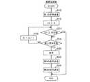
図3は歩行者等100によって操作される携帯型端末の処理を示すフロー・チャート、図4は歩行者等100によって携帯される携帯型端末の表示部を示す説明図である。 FIG. 3 is a flowchart showing processing of a portable terminal operated by a pedestrian or the like 100, and FIG. 4 is an explanatory diagram showing a display unit of the portable terminal carried by the pedestrian or the like 100.
以下説明すると、S(ステップ)10において、歩行者等100が横断歩道を渡ろうとする(走行路を横断する)際、携帯型端末102を操作して第1の信号(後述)を車両10、より具体的には車両10のECU38にアンテナ102aとアンテナ70f1を介して送信する。 As will be described below, in S (step) 10, when a pedestrian or the like 100 is about to cross a pedestrian crossing (crossing a traveling road), the
ここで図4を参照して携帯型端末102から送信される信号について説明する。図4に示すように、携帯型端末102の表示部102bには、例えば、「渡りたい」(102b1)、「横断開始」(102b2)、「横断終了」(102b3)といった、予め想定される歩行者等100の移動計画が表示される。歩行者等100は、表示部102bに表示される移動計画102b1,102b2,102b3のいずれかを適宜選択することにより、車両10側に自己の移動計画(信号)を伝える(送信する)ことができる。 Here, a signal transmitted from the
ここで、上記する移動計画のうち、「渡りたい」(102b1)なる移動計画に基づき車両10側に送信される信号が第1の信号、「横断開始」(102b2。後述)なる移動計画に基づき車両10側に送信される信号が第2の信号、「横断終了」(102b3。後述)なる移動計画に基づき車両10側に送信される信号が第3の信号に相当する。 Here, among the above-mentioned movement plans, the signal transmitted to the
図3フロー・チャートの説明に戻ると、次いでS12に進み、カウンタタイマC1の値を0にリセットし、S14に進み、カウンタタイマC1の値が所定値以上となったか否か判断する。 Returning to the description of the flow chart of FIG. 3, the process then proceeds to S12, the value of the counter timer C1 is reset to 0, and the process proceeds to S14, where it is determined whether or not the value of the counter timer C1 has become a predetermined value or more.
所定値は、車両10のECU38がアンテナ70f1を介して第1の信号を受信し、それに応じて適切な制御(停止制御)を行ったか否かを判断するのに適した値に設定される。即ち、後述する如く、車両10のECU38は、携帯型端末102から送信された第1の信号を受信すると車両10を停止させ、携帯型端末に対して信号を返信するように構成されることから、カウンタタイマC1の値が所定値に達した場合は何らかの原因により車両10が第1の信号を受信しなかった、あるいは受信したものの適切な停止制御を行うことができなかったものと判断することができる。 The predetermined value is set to a value suitable for determining whether the
S14で否定されるときはS16に進み、車両10のECU38から送信される停止信号を受信したか否か判断する。S16で否定されるときはS18に進み、カウンタタイマC1の値を1つインクリメントしてS14に戻る。即ち、カウンタタイマC1の値が所定値に達するまでの時間(所定時間)内に停止信号を受信するか、あるいはカウンタタイマC1の値が所定値に達するまでS14からS18までの処理が繰り返される。 When the result in S14 is negative, the program proceeds to S16, in which it is determined whether or not a stop signal transmitted from the
従って、S14で肯定されるときは所定時間内に車両10のECU38から停止信号を受信しなかった、換言すれば車両10が停止していないと判断されることからプログラムを終了する。 Therefore, when the result in S14 is affirmative, it is determined that the stop signal has not been received from the
S16で肯定されるとき、即ち所定時間内に停止信号を受信した場合はS20に進み、携帯型端末102の表示部102bに車両が停止した旨を表示すると共に、S22に進み、歩行者等100による携帯型端末102の操作に応じて第2の信号を車両10のECU38に送信する。即ち、歩行者等100は車両10が停止したことを受信した停止信号により確認した後、携帯型端末102を操作して横断歩道の歩行(横断)を開始した旨の信号(第2の信号)を車両10のECU38に送信する。 When the result in S16 is affirmative, that is, when a stop signal is received within a predetermined time, the process proceeds to S20, the fact that the vehicle has stopped is displayed on the
歩行者等100が横断を終了した場合、S24に進み、歩行者等100による携帯型端末102の操作に応じて第3の信号を車両10のECU38に送信し、プログラムを終了する。 When the
このように、この発明の実施例においては、車両10のECU38は携帯型端末102を介して歩行者等100から送信される歩行者等100の移動計画(横断意図。第1から第3の信号)を受信することが可能となり、よって歩行者の意図に応じた積極的かつ的確な車両の走行制御を行うことが可能となる。 As described above, in the embodiment of the present invention, the
尚、携帯型端末102は、初めから第1から第3の信号全てに対応する送信ボタン等を備えるように構成しても良いし、単一の送信機能のみを備えるようにし、車両10に移動計画を送信する回数に応じて車両10に送信される信号(第1から第3の信号)が自動的に切り換わる、換言すれば、車両10に移動計画を送信する回数に応じて送信される移動計画102b1,102b2,102b3を変更するようにしても良い。また、予め定められた順番で1つずつ移動計画102b1,102b2,102b3を表示、換言すれば表示部102bに表示される移動計画102b1,102b2,102b3が所定の順番で変更されるようにしても良い。 Note that the
図5は、上記した携帯型端末102の処理と協調して行われる車両10のECU38による処理を示すフロー・チャートである。 FIG. 5 is a flowchart showing a process performed by the
以下説明すると、S100において携帯型端末102から送信される第1の信号を受信したか否か判断する。尚、第1の信号を受信してS100で肯定されるまで以降の処理は行われない。 In the following, it is determined whether or not the first signal transmitted from the
S100で肯定されるときはS102に進み、車両10のナビゲーション装置に備えられる表示部70eに、例えば、「この先、横断を希望する歩行者がいます。」といった表示をすると共に、警報装置22を用いて車両10の運転者に音声等による同様の警報を行う。 When the result in S100 is affirmative, the process proceeds to S102, and the
次いでS104に進み、車両10を安全に停止させることが可能であるか否か判断する。即ち、現在の車速と歩行者等100が横断を希望する横断歩道までの距離等に基づき、車両を安全に停止させることが可能であるか判断する。 Next, in S104, it is determined whether or not the
車両10を安全に停止させることができないと判断されるときはS104の判断は否定され、プログラムを終了する。尚、この際歩行者等100の携帯型端末102に対し、車両10が停止することができない旨の信号を送信しても良い。 If it is determined that the
他方、車両10を安全に停止させることが可能であると判断されるときはS106に進み、表示部70eおよび警報装置22を介して運転者に対し車両の停止を指示、あるいはブレーキ油圧機構32に直接指令を送り、各車輪16に装着されたブレーキ34を動作させて車両10を停止させる。 On the other hand, when it is determined that the
車両10が停止した場合、次いでS108に進み、車両10が停止した旨を表す停止信号をアンテナ70f1を介して歩行者等100の携帯型端末102に送信する。尚、ECU38から送信されるこの停止信号が、携帯型端末102がS16の処理で受信する停止信号に相当する。 When the
次いでS110に進み、歩行者等100から携帯型端末102を介して送信される第2の信号(S22)を受信したか否か判断する処理を繰り返す、換言すれば、第2の信号を受信するまで待機する。 Next, the process proceeds to S110 and repeats the process of determining whether or not the second signal (S22) transmitted from the pedestrian or the like 100 via the
第2の信号を受信するとS112に進み、表示部70eに、例えば、「歩行者が横断中です。」といった表示をすると共に、警報装置22を用いて車両10の運転者に音声等による同様の警報を行う。また、この間は車両10の再発進を禁止する。 When the second signal is received, the process proceeds to S112, where, for example, “Pedestrian is crossing” is displayed on the
次いでS114に進み、歩行者等100から携帯型端末102を介して送信される第3の信号(S24)を受信したか否か判断、換言すれば、第3の信号を受信し、歩行者等100が横断を終了したと判断できるまで車両10を停止させたまま待機する。 Next, in S114, it is determined whether or not the third signal (S24) transmitted from the pedestrian or the like 100 via the
S114で肯定され、歩行者等100が横断歩道の横断を終了したと判断されるときはS116に進み、表示部70eや報知手段22を介して運転者に車両10の再発進を指示してプログラムを終了する。尚、車両10を自動走行させる場合はECU38の指示により車両10を再発進させる。 When the result in S114 is affirmative and it is determined that the pedestrian or the like 100 has finished crossing the pedestrian crossing, the program proceeds to S116, in which the driver is instructed to restart the
上記したように、この発明の実施例においては、車両10のECU38は携帯型端末102を介して送信される歩行者等100の移動計画(横断意図)に応じて積極的かつ的確な車両の走行制御を行うことが可能となる。尚、上記したS100からS116に示す処理、より正確にはS104からS106,S110からS116に示す処理が走行計画作成手段に相当する。 As described above, in the embodiment of the present invention, the
図6および図7は上記した車両10のECU38の処理の変形例を示すフロー・チャートである。 6 and 7 are flowcharts showing a modification of the processing of the
先ず図6に示す第1の変形例について説明すると、S200からS214まではS100からS114までと同じ処理を行う。 First, the first modification shown in FIG. 6 will be described. From S200 to S214, the same processing as S100 to S114 is performed.
S214で肯定されるときはS216に進み、S116同様、運転者に車両10の再発信を指示してプログラムを終了する。他方、S214で否定されるときはS218に進み、レーダ装置42や撮影装置44を用いて横断歩道に歩行者(移動体)100が存在するか否か確認する。 When the result in S214 is affirmative, the program proceeds to S216, and in the same manner as S116, the driver is instructed to retransmit the
S218で肯定されるときは、歩行者等100が横断中であると判断されることから、S214に戻り上記した処理を繰り返す。他方、S218で否定、即ち歩行者等100が横断を終了し、安全が確認されたと判断できるときはS216に進み、運転者に車両10の再発進を指示してプログラムを終了する。 When the result in S218 is affirmative, since it is determined that the
即ち、歩行者等100が横断を終了したにもかかわらず、第3の信号を送信することなくそのまま通過する事態も考えられることから、この変形例においては、ECU38が第3の信号を受信しない場合であっても、レーダ装置42や撮影装置44を介して歩行者等100が横断を終了したか否かを判断し、横断を終了したと判断できる場合は速やかに車両10を再発進できるようにした。 That is, even though the
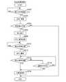
次に図7に示す第2の変形例について説明する。第2の変形例にあっては、S300からS312まではS100からS112およびS200からS212と同じ処理を行う。 Next, a second modification shown in FIG. 7 will be described. In the second modification, the same processes as S100 to S112 and S200 to S212 are performed from S300 to S312.
S314ではカウンタタイマC2の値を0にリセットし、S316に進み、カウンタタイマC2の値が既定値以上となったか否か判断される。 In S314, the value of the counter timer C2 is reset to 0, and the process proceeds to S316, in which it is determined whether or not the value of the counter timer C2 is equal to or greater than a predetermined value.
既定値は、歩行者等100が横断を開始してから横断を終了するまでに要すると考えられる時間(既定時間)に応じた値に設定される。即ち、この変形例では、携帯型端末102を介して歩行者等100から第2の信号を受信した後、既定時間を経過したか否かを判断することにより、歩行者等100が第3の信号を送信し忘れたような場合であっても速やかに車両10を再発進できるようにした。 The predetermined value is set to a value corresponding to a time (predetermined time) that is considered to be required from when the pedestrian or the like 100 starts crossing to the end of the crossing. That is, in this modification, after receiving the second signal from the pedestrian etc. 100 via the
但し、既定時間は歩行者等100が横断を終了するのに十分な時間を見越して設定されることから、既定時間を経過する前に第3の信号を受信する場合もあり得る。そこで、S316で否定される場合にあっても、S318に進み、S114やS214と同様、第3の信号を受信したか否かを判断し、肯定されるときはS320に進み、運転者に車両10の再発進を指示する一方、S218で否定される場合はS320に進み、カウンタタイマC2の値を1つインクリメントしてS316に戻る。 However, since the predetermined time is set in anticipation of a time sufficient for the pedestrian or the like 100 to complete the crossing, the third signal may be received before the predetermined time elapses. Therefore, even in the case of negative in S316, the process proceeds to S318, and similarly to S114 and S214, it is determined whether or not a third signal has been received. If the result of S218 is negative, the process proceeds to S320, the value of the counter timer C2 is incremented by 1, and the process returns to S316.
S316で肯定され、既定時間が経過したと判断されるときはS322に進み、S218と同様、レーダ装置42や撮影装置44を用いて横断歩道に歩行者等100が存在するか否か確認する。 When the result in S316 is affirmative and it is determined that the predetermined time has elapsed, the process proceeds to S322, and it is checked whether there is a
S322で否定されるときは、レーダ装置42や撮影装置44によって歩行者等100が歩行を終了し、安全が確認されたと判断できるまで待機する一方、S322で肯定されるときはS320に進み、車両10の再発進を指示してプログラムを終了する。 When the result in S322 is negative, the
上記した如く、この発明の実施例にあっては、歩行者等(移動体)100に携帯される携帯型端末102を介して前記歩行者等100と通信可能な車両10の制御装置(ECU38)において、前記携帯型端末102から送信される前記歩行者の移動計画(102b1,102b2,102b3。第1から第3の信号)を受信する受信手段(ECU38、アンテナ70f1。S100,S110,S114)と、前記受信した前記歩行者等100の移動計画に応じて前記車両10の走行計画を作成する走行計画作成手段(ECU38。S104からS106,S110からS116,S204からS206,S210からS21S218,S304からS306,S310からS322)と、前記作成された走行計画を前記車両の運転者に報知する報知手段(ECU38、警報装置22、表示部70e。S106,S112,S116,S206,S212,S216,S306,S312,S320)とを備えるように構成したので、車両10側において歩行者等100の移動計画を把握することが可能となり、よって歩行者等100の移動計画に基づいた積極的かつ的確な車両10の走行制御を行うことが可能となる。 As described above, in the embodiment of the present invention, the control device (ECU 38) for the
特に、移動体100が歩行者や電動車椅子などの低速移動体からなる場合は、歩道に沿って移動する場合のみならず走行路を横断することもあり、車両10に比して移動の自由度が高いことから、車両10側が歩行者等100の位置を把握していても、それのみではその行動を正確に予測することが困難な場合も多く、車両10側で積極的かつ的確な走行制御を行うのは難しい。しかしながら、この発明の実施例に係る車両の制御装置(ECU38)にあっては、歩行者等(移動体)100によって携帯される携帯型端末102を介して歩行者等100の移動計画102b1,102b2,102b3(第1から第3の信号)、より具体的にはその行動意図を受信するように構成したので、歩行者等100の行動意図(移動計画)を容易に把握することが可能となり、車両10側において積極的かつ的確な走行制御を行うことが可能となる。 In particular, when the moving
また、前記携帯型端末102から送信される前記歩行者等100の移動計画102b1,102b2,102b3(第1から第3の信号)を受信する受信手段(ECU38、アンテナ70f1)と、前記受信した前記歩行者等100の移動計画に応じて前記車両10の走行計画を作成する走行計画作成手段(ECU38。S104からS106,S116,S204からS206,S216,S218,S304からS306,S316,S320,S322)と、前記作成された走行計画に基づいて前記車両の挙動を制御する挙動制御手段(ECU38、ブレーキ油圧機構32。S106,S116,S206,S216,S306,S320)とを備えるように構成したので、上記した効果に加え、自動走行運転制御を行う場合にあっても、歩行者等100の移動計画に基づいた積極的かつ的確な車両10の走行制御を行うことが可能となる。 Further, receiving means (
また、前記携帯型端末102から送信される前記歩行者等100の移動計画は、少なくとも前記歩行者等100の道路横断意図102b1からなる如く構成したので、上記した効果に加え、歩行者等100の横断意図に応じて車両10を停止するように車両10の走行制御を行うことが可能となる。 Moreover, since the movement plan of the
また、前記携帯型端末102は、予め設定される複数の移動計画(102b1,102b2,102b3)のうちから選択された一の移動計画を送信する如く構成したので、上記した効果に加え、歩行者等100の移動計画をより正確かつ容易に把握することが可能となり、よって歩行者等100の移動計画に基づいたより積極的かつ的確な車両10の走行制御を行うことが可能となる。 Further, since the
また、前記携帯型端末は、予め設定される複数の移動計画(102b1,102b2,102b3)を有すると共に、前記移動計画を前記車両10に送信する回数に応じて前記送信される移動計画を変更する如く構成したので、上記した効果に加え、歩行者等100の移動計画をより正確かつ容易に把握することが可能となり、よって歩行者等100の移動計画に基づいたより積極的かつ的確な車両10の走行制御を行うことが可能となる。 The portable terminal has a plurality of preset movement plans (102b1, 102b2, 102b3), and changes the transmitted movement plan according to the number of times the movement plan is transmitted to the
また、前記携帯型端末102は、予め設定される複数の移動計画(102b1,102b2,102b3)を有すると共に、前記移動計画が所定の順番で変更される如く構成したので、上記した効果に加え、歩行者等100の移動計画をより正確かつ容易に把握することが可能となり、よって歩行者等100の移動計画に基づいたより積極的かつ的確な車両10の走行制御を行うことが可能となる。 Moreover, since the
また、前記携帯型端末102は、前記送信する移動計画を表示する表示手段(表示部)102bを有する如く構成したので、上記した効果に加え、歩行者等100において適宜的確な移動計画を容易に選択し、送信することが可能となり、より積極的かつ的確な車両10の走行制御を行うことが可能となる。 Further, since the
尚、実施例では、レーダ装置42や撮影装置44に加え、ミリ波レーダや超音波ソナー等を使用することにも触れたが、車両10周囲に存在する移動体100を検知することができれば良く、必ずしもこれらを全て備えている必要はない。また、レーダ42aやカメラ44aの数や配置についても、上記した実施例に限定されるものではない。 In the embodiment, the use of a millimeter wave radar, an ultrasonic sonar or the like in addition to the
また、実施例では移動体100として歩行者を例にとって説明したが、移動体100はこれに限られるものではなく、例えば電動車椅子や他の車両などであっても良い。 In the embodiment, the pedestrian is described as an example of the moving
また、携帯型端末102はGPSを利用して自己の現在位置を算出できるものであってもよく、携帯型端末102から送信される信号に、移動体100の移動計画を表す第1から第3の信号に加え、携帯型端末102の現在位置を示す信号を含めても良い。この場合、ECU38は携帯型端末102から送信される現在位置信号と現在位置検出部70aで算出される車両10の現在位置情報に基づいて車両10と移動体100の相対位置等を算出するように構成しても良い。 In addition, the
10 車両、22 警報装置、32、ブレーキ油圧機構、38 ECU(車両の制御装置、走行計画作成手段、挙動制御手段)、42 レーダ装置、44 撮影装置、70 ナビゲーション装置、70e 表示部、70f 通信部、70f1 アンテナ、100 移動体、102 携帯型端末、102a アンテナ、102b 表示部、102b1,102b2,102b3 移動計画 DESCRIPTION OF
Claims (7)
Translated fromJapaneseThe vehicle control device according to claim 1, wherein the portable terminal has display means for displaying the travel plan to be transmitted.
Priority Applications (3)
| Application Number | Priority Date | Filing Date | Title |
|---|---|---|---|
| JP2013207501AJP2015072570A (en) | 2013-10-02 | 2013-10-02 | Vehicle control device |
| DE102014219665.5ADE102014219665B4 (en) | 2013-10-02 | 2014-09-29 | Vehicle control device |
| US14/501,185US20150094878A1 (en) | 2013-10-02 | 2014-09-30 | Vehicle control apparatus |
Applications Claiming Priority (1)
| Application Number | Priority Date | Filing Date | Title |
|---|---|---|---|
| JP2013207501AJP2015072570A (en) | 2013-10-02 | 2013-10-02 | Vehicle control device |
Publications (1)
| Publication Number | Publication Date |
|---|---|
| JP2015072570Atrue JP2015072570A (en) | 2015-04-16 |
Family
ID=52673405
Family Applications (1)
| Application Number | Title | Priority Date | Filing Date |
|---|---|---|---|
| JP2013207501AWithdrawnJP2015072570A (en) | 2013-10-02 | 2013-10-02 | Vehicle control device |
Country Status (3)
| Country | Link |
|---|---|
| US (1) | US20150094878A1 (en) |
| JP (1) | JP2015072570A (en) |
| DE (1) | DE102014219665B4 (en) |
Cited By (8)
| Publication number | Priority date | Publication date | Assignee | Title |
|---|---|---|---|---|
| JP2018520421A (en)* | 2015-05-19 | 2018-07-26 | ローベルト ボツシユ ゲゼルシヤフト ミツト ベシユレンクテル ハフツングRobert Bosch Gmbh | Highly automated car control |
| JP2018151714A (en)* | 2017-03-10 | 2018-09-27 | みこらった株式会社 | Mobile terminal, automobile, and communication system |
| JP2020024708A (en)* | 2018-05-31 | 2020-02-13 | みこらった株式会社 | Portable terminal, automobile, and communication system |
| US10657822B2 (en) | 2017-11-09 | 2020-05-19 | Toyota Jidosha Kabushiki Kaisha | Vehicle control device |
| US10857939B2 (en) | 2018-10-10 | 2020-12-08 | Toyota Jidosha Kabushiki Kaisha | Notification device |
| US10943472B2 (en) | 2018-11-14 | 2021-03-09 | Toyota Jidosha Kabushiki Kaisha | Notification device |
| JP2022145203A (en)* | 2021-03-19 | 2022-10-03 | トヨタ自動車株式会社 | Pedestrian-vehicle communication system |
| JP2023026499A (en)* | 2019-09-18 | 2023-02-24 | みこらった株式会社 | Automobile, communication system, and program for automobiles |
Families Citing this family (12)
| Publication number | Priority date | Publication date | Assignee | Title |
|---|---|---|---|---|
| US10377374B1 (en)* | 2013-11-06 | 2019-08-13 | Waymo Llc | Detection of pedestrian using radio devices |
| DE102014201159A1 (en)* | 2014-01-23 | 2015-07-23 | Robert Bosch Gmbh | Method and device for classifying a behavior of a pedestrian when crossing a roadway of a vehicle and personal protection system of a vehicle |
| EP2982562A1 (en) | 2014-08-08 | 2016-02-10 | Nokia Technologies OY | Vehicle control |
| US20160292996A1 (en)* | 2015-03-30 | 2016-10-06 | Hoseotelnet Co., Ltd. | Pedestrian detection radar using ultra-wide band pulse and traffic light control system including the same |
| DE102016001124A1 (en) | 2016-02-02 | 2017-08-03 | Audi Ag | Sensor unit, motor vehicle and method for the detection of pedestrians based on your mobile devices |
| US20180222473A1 (en)* | 2017-02-09 | 2018-08-09 | GM Global Technology Operations LLC | Collision avoidance for personal mobility devices |
| DE102017202245B4 (en) | 2017-02-13 | 2022-10-27 | Audi Ag | Communications device for an autopilot-controlled motor vehicle for sending addressed coordination signals to communication partners |
| JP2019197467A (en)* | 2018-05-11 | 2019-11-14 | トヨタ自動車株式会社 | Vehicle control device |
| US10780897B2 (en)* | 2019-01-31 | 2020-09-22 | StradVision, Inc. | Method and device for signaling present driving intention of autonomous vehicle to humans by using various V2X-enabled application |
| EP3706454B1 (en)* | 2019-03-08 | 2024-05-15 | Volkswagen Aktiengesellschaft | Apparatus, method and computer program for determining a duplex resource scheme for a localized communication in a mobile communication system |
| DE102019127930B4 (en) | 2019-10-16 | 2022-01-20 | Audi Ag | Method for determining the position of a non-motorized road user and traffic facility |
| RU2749901C1 (en)* | 2020-08-20 | 2021-06-18 | Кириллов Александр Викторович | Method for informing drivers about presence of pedestrians at pedestrian crossing |
Family Cites Families (10)
| Publication number | Priority date | Publication date | Assignee | Title |
|---|---|---|---|---|
| US20070069920A1 (en)* | 2005-09-23 | 2007-03-29 | A-Hamid Hakki | System and method for traffic related information display, traffic surveillance and control |
| GB0717741D0 (en)* | 2007-09-12 | 2007-10-17 | Spillard Saftey Systems Ltd | Proximity apparatus |
| DE102008049824B4 (en)* | 2008-10-01 | 2014-09-04 | Universität Kassel | Method for collision avoidance |
| DE102008061910A1 (en)* | 2008-12-15 | 2009-09-03 | Daimler Ag | Movable object i.e. vehicle, action detecting and forecasting method, involves producing hypothesis of prospective movement of object based on measure of similarity between trajectories and/or between partial sections of trajectories |
| DE102009035072A1 (en)* | 2009-07-28 | 2011-02-10 | Bayerische Motoren Werke Aktiengesellschaft | Motor vehicle collision warning system has a transceiver working with a transponder at the object in the path, e.g. a pedestrian, to determine its position and predict its future position |
| JP2011210250A (en) | 2010-03-11 | 2011-10-20 | Rcs:Kk | Safe driving support system for traveling vehicle |
| US8600411B2 (en)* | 2012-01-23 | 2013-12-03 | Qualcomm Incorporated | Methods and apparatus for controlling the transmission and/or reception of safety messages by portable wireless user devices |
| US10089537B2 (en)* | 2012-05-18 | 2018-10-02 | Magna Electronics Inc. | Vehicle vision system with front and rear camera integration |
| DE102012215060A1 (en)* | 2012-08-24 | 2014-02-27 | Robert Bosch Gmbh | Method for guiding vehicle, involves detecting parameter of environment of vehicle on basis of sensor, and determining driving corridor and desire point in driving corridor on basis of detected parameter |
| JP6429368B2 (en)* | 2013-08-02 | 2018-11-28 | 本田技研工業株式会社 | Inter-vehicle communication system and method |
- 2013
- 2013-10-02JPJP2013207501Apatent/JP2015072570A/ennot_activeWithdrawn
- 2014
- 2014-09-29DEDE102014219665.5Apatent/DE102014219665B4/ennot_activeExpired - Fee Related
- 2014-09-30USUS14/501,185patent/US20150094878A1/ennot_activeAbandoned
Cited By (17)
| Publication number | Priority date | Publication date | Assignee | Title |
|---|---|---|---|---|
| JP2018520421A (en)* | 2015-05-19 | 2018-07-26 | ローベルト ボツシユ ゲゼルシヤフト ミツト ベシユレンクテル ハフツングRobert Bosch Gmbh | Highly automated car control |
| JP2018151714A (en)* | 2017-03-10 | 2018-09-27 | みこらった株式会社 | Mobile terminal, automobile, and communication system |
| US11900812B2 (en) | 2017-11-09 | 2024-02-13 | Toyota Jidosha Kabushiki Kaisha | Vehicle control device |
| US10657822B2 (en) | 2017-11-09 | 2020-05-19 | Toyota Jidosha Kabushiki Kaisha | Vehicle control device |
| US11631330B2 (en) | 2017-11-09 | 2023-04-18 | Toyota Jidosha Kabushiki Kaisha | Vehicle control device |
| JP2020024708A (en)* | 2018-05-31 | 2020-02-13 | みこらった株式会社 | Portable terminal, automobile, and communication system |
| US10857939B2 (en) | 2018-10-10 | 2020-12-08 | Toyota Jidosha Kabushiki Kaisha | Notification device |
| US11364842B2 (en) | 2018-10-10 | 2022-06-21 | Toyota Jidosha Kabushiki Kaisha | Notification device |
| US11926256B2 (en) | 2018-10-10 | 2024-03-12 | Toyota Jidosha Kabushiki Kaisha | Notification device |
| US11752929B2 (en) | 2018-10-10 | 2023-09-12 | Toyota Jidosha Kabushiki Kaisha | Notification device |
| US10943472B2 (en) | 2018-11-14 | 2021-03-09 | Toyota Jidosha Kabushiki Kaisha | Notification device |
| US11605289B2 (en) | 2018-11-14 | 2023-03-14 | Toyota Jidosha Kabushiki Kaisha | Notification device |
| JP2023026499A (en)* | 2019-09-18 | 2023-02-24 | みこらった株式会社 | Automobile, communication system, and program for automobiles |
| JP2024009087A (en)* | 2019-09-18 | 2024-01-19 | みこらった株式会社 | Communication systems, automobiles, mobile terminals, programs for automobiles, and programs for mobile terminals |
| JP7391427B2 (en) | 2019-09-18 | 2023-12-05 | みこらった株式会社 | Automotive and communication systems, and automotive programs |
| JP2022145203A (en)* | 2021-03-19 | 2022-10-03 | トヨタ自動車株式会社 | Pedestrian-vehicle communication system |
| JP7743704B2 (en) | 2021-03-19 | 2025-09-25 | トヨタ自動車株式会社 | Pedestrian-to-vehicle communication system |
Also Published As
| Publication number | Publication date |
|---|---|
| US20150094878A1 (en) | 2015-04-02 |
| DE102014219665B4 (en) | 2016-10-13 |
| DE102014219665A1 (en) | 2015-04-02 |
Similar Documents
| Publication | Publication Date | Title |
|---|---|---|
| JP2015072570A (en) | Vehicle control device | |
| JP7090576B2 (en) | Vehicle control system | |
| CN108995644B (en) | steering assist system | |
| JP6583061B2 (en) | Automatic operation control device | |
| US10589786B2 (en) | Steering assist device | |
| JP6801591B2 (en) | Steering support device | |
| EP3412539A1 (en) | Lane change assist device | |
| US20180346027A1 (en) | Steering assist device | |
| KR101511858B1 (en) | Advanced Driver Assistance System(ADAS) and controlling method for the same | |
| US20190071071A1 (en) | Vehicle control device, vehicle control method, and storage medium | |
| CN112660154A (en) | Vehicle control system | |
| CN108973994A (en) | Vehicle control system, control method for vehicle and storage medium | |
| CN109388137B (en) | Driving assistance apparatus and storage medium | |
| JP6788751B2 (en) | Vehicle control devices, vehicle control methods, and programs | |
| JP2022060078A (en) | Driving support device | |
| CN112124091B (en) | Parking assist system | |
| JP7035447B2 (en) | Vehicle control unit | |
| WO2020194715A1 (en) | Saddled vehicle | |
| CN109318792A (en) | Vehicle external notification device | |
| CN110217228B (en) | Vehicle control device, vehicle control method, and storage medium | |
| JP7461989B2 (en) | Driving assistance device, driving assistance method, and program | |
| JP2015074380A (en) | Vehicle travel control device | |
| CN115223397A (en) | traffic system | |
| JP7075789B2 (en) | Vehicle control devices, vehicle control methods, and programs | |
| JP2018039418A (en) | Vehicle control device |
Legal Events
| Date | Code | Title | Description |
|---|---|---|---|
| A621 | Written request for application examination | Free format text:JAPANESE INTERMEDIATE CODE: A621 Effective date:20151127 | |
| A761 | Written withdrawal of application | Free format text:JAPANESE INTERMEDIATE CODE: A761 Effective date:20160714 |