JP2015061663A - Delivery tube, system and method for retaining liquid from a tissue site - Google Patents
Delivery tube, system and method for retaining liquid from a tissue siteDownload PDFInfo
- Publication number
- JP2015061663A JP2015061663AJP2014246851AJP2014246851AJP2015061663AJP 2015061663 AJP2015061663 AJP 2015061663AJP 2014246851 AJP2014246851 AJP 2014246851AJP 2014246851 AJP2014246851 AJP 2014246851AJP 2015061663 AJP2015061663 AJP 2015061663A
- Authority
- JP
- Japan
- Prior art keywords
- reduced pressure
- lumen
- tissue site
- tube
- fluid
- Prior art date
- Legal status (The legal status is an assumption and is not a legal conclusion. Google has not performed a legal analysis and makes no representation as to the accuracy of the status listed.)
- Granted
Links
Images


Classifications
- A—HUMAN NECESSITIES
- A61—MEDICAL OR VETERINARY SCIENCE; HYGIENE
- A61M—DEVICES FOR INTRODUCING MEDIA INTO, OR ONTO, THE BODY; DEVICES FOR TRANSDUCING BODY MEDIA OR FOR TAKING MEDIA FROM THE BODY; DEVICES FOR PRODUCING OR ENDING SLEEP OR STUPOR
- A61M25/00—Catheters; Hollow probes
- A61M25/0021—Catheters; Hollow probes characterised by the form of the tubing
- A61M25/0023—Catheters; Hollow probes characterised by the form of the tubing by the form of the lumen, e.g. cross-section, variable diameter
- A61M25/0026—Multi-lumen catheters with stationary elements
- A61M25/003—Multi-lumen catheters with stationary elements characterized by features relating to least one lumen located at the distal part of the catheter, e.g. filters, plugs or valves
- A—HUMAN NECESSITIES
- A61—MEDICAL OR VETERINARY SCIENCE; HYGIENE
- A61M—DEVICES FOR INTRODUCING MEDIA INTO, OR ONTO, THE BODY; DEVICES FOR TRANSDUCING BODY MEDIA OR FOR TAKING MEDIA FROM THE BODY; DEVICES FOR PRODUCING OR ENDING SLEEP OR STUPOR
- A61M1/00—Suction or pumping devices for medical purposes; Devices for carrying-off, for treatment of, or for carrying-over, body-liquids; Drainage systems
- A—HUMAN NECESSITIES
- A61—MEDICAL OR VETERINARY SCIENCE; HYGIENE
- A61F—FILTERS IMPLANTABLE INTO BLOOD VESSELS; PROSTHESES; DEVICES PROVIDING PATENCY TO, OR PREVENTING COLLAPSING OF, TUBULAR STRUCTURES OF THE BODY, e.g. STENTS; ORTHOPAEDIC, NURSING OR CONTRACEPTIVE DEVICES; FOMENTATION; TREATMENT OR PROTECTION OF EYES OR EARS; BANDAGES, DRESSINGS OR ABSORBENT PADS; FIRST-AID KITS
- A61F13/00—Bandages or dressings; Absorbent pads
- A61F13/02—Adhesive bandages or dressings
- A—HUMAN NECESSITIES
- A61—MEDICAL OR VETERINARY SCIENCE; HYGIENE
- A61M—DEVICES FOR INTRODUCING MEDIA INTO, OR ONTO, THE BODY; DEVICES FOR TRANSDUCING BODY MEDIA OR FOR TAKING MEDIA FROM THE BODY; DEVICES FOR PRODUCING OR ENDING SLEEP OR STUPOR
- A61M1/00—Suction or pumping devices for medical purposes; Devices for carrying-off, for treatment of, or for carrying-over, body-liquids; Drainage systems
- A61M1/90—Negative pressure wound therapy devices, i.e. devices for applying suction to a wound to promote healing, e.g. including a vacuum dressing
- A61M1/91—Suction aspects of the dressing
- A61M1/915—Constructional details of the pressure distribution manifold
- A—HUMAN NECESSITIES
- A61—MEDICAL OR VETERINARY SCIENCE; HYGIENE
- A61M—DEVICES FOR INTRODUCING MEDIA INTO, OR ONTO, THE BODY; DEVICES FOR TRANSDUCING BODY MEDIA OR FOR TAKING MEDIA FROM THE BODY; DEVICES FOR PRODUCING OR ENDING SLEEP OR STUPOR
- A61M25/00—Catheters; Hollow probes
- A61M25/01—Introducing, guiding, advancing, emplacing or holding catheters
- A61M25/02—Holding devices, e.g. on the body
- A—HUMAN NECESSITIES
- A61—MEDICAL OR VETERINARY SCIENCE; HYGIENE
- A61M—DEVICES FOR INTRODUCING MEDIA INTO, OR ONTO, THE BODY; DEVICES FOR TRANSDUCING BODY MEDIA OR FOR TAKING MEDIA FROM THE BODY; DEVICES FOR PRODUCING OR ENDING SLEEP OR STUPOR
- A61M27/00—Drainage appliance for wounds or the like, i.e. wound drains, implanted drains
- A—HUMAN NECESSITIES
- A61—MEDICAL OR VETERINARY SCIENCE; HYGIENE
- A61M—DEVICES FOR INTRODUCING MEDIA INTO, OR ONTO, THE BODY; DEVICES FOR TRANSDUCING BODY MEDIA OR FOR TAKING MEDIA FROM THE BODY; DEVICES FOR PRODUCING OR ENDING SLEEP OR STUPOR
- A61M1/00—Suction or pumping devices for medical purposes; Devices for carrying-off, for treatment of, or for carrying-over, body-liquids; Drainage systems
- A61M1/90—Negative pressure wound therapy devices, i.e. devices for applying suction to a wound to promote healing, e.g. including a vacuum dressing
- A61M1/94—Negative pressure wound therapy devices, i.e. devices for applying suction to a wound to promote healing, e.g. including a vacuum dressing with gas supply means
- A—HUMAN NECESSITIES
- A61—MEDICAL OR VETERINARY SCIENCE; HYGIENE
- A61M—DEVICES FOR INTRODUCING MEDIA INTO, OR ONTO, THE BODY; DEVICES FOR TRANSDUCING BODY MEDIA OR FOR TAKING MEDIA FROM THE BODY; DEVICES FOR PRODUCING OR ENDING SLEEP OR STUPOR
- A61M1/00—Suction or pumping devices for medical purposes; Devices for carrying-off, for treatment of, or for carrying-over, body-liquids; Drainage systems
- A61M1/90—Negative pressure wound therapy devices, i.e. devices for applying suction to a wound to promote healing, e.g. including a vacuum dressing
- A61M1/98—Containers specifically adapted for negative pressure wound therapy
- A61M1/982—Containers specifically adapted for negative pressure wound therapy with means for detecting level of collected exudate
- A—HUMAN NECESSITIES
- A61—MEDICAL OR VETERINARY SCIENCE; HYGIENE
- A61M—DEVICES FOR INTRODUCING MEDIA INTO, OR ONTO, THE BODY; DEVICES FOR TRANSDUCING BODY MEDIA OR FOR TAKING MEDIA FROM THE BODY; DEVICES FOR PRODUCING OR ENDING SLEEP OR STUPOR
- A61M25/00—Catheters; Hollow probes
- A61M25/0021—Catheters; Hollow probes characterised by the form of the tubing
- A61M25/0023—Catheters; Hollow probes characterised by the form of the tubing by the form of the lumen, e.g. cross-section, variable diameter
- A61M25/0026—Multi-lumen catheters with stationary elements
- A61M2025/0034—Multi-lumen catheters with stationary elements characterized by elements which are assembled, connected or fused, e.g. splittable tubes, outer sheaths creating lumina or separate cores
- A—HUMAN NECESSITIES
- A61—MEDICAL OR VETERINARY SCIENCE; HYGIENE
- A61M—DEVICES FOR INTRODUCING MEDIA INTO, OR ONTO, THE BODY; DEVICES FOR TRANSDUCING BODY MEDIA OR FOR TAKING MEDIA FROM THE BODY; DEVICES FOR PRODUCING OR ENDING SLEEP OR STUPOR
- A61M25/00—Catheters; Hollow probes
- A61M25/0021—Catheters; Hollow probes characterised by the form of the tubing
- A61M25/0023—Catheters; Hollow probes characterised by the form of the tubing by the form of the lumen, e.g. cross-section, variable diameter
- A61M25/0026—Multi-lumen catheters with stationary elements
- A61M2025/0036—Multi-lumen catheters with stationary elements with more than four lumina
- A—HUMAN NECESSITIES
- A61—MEDICAL OR VETERINARY SCIENCE; HYGIENE
- A61M—DEVICES FOR INTRODUCING MEDIA INTO, OR ONTO, THE BODY; DEVICES FOR TRANSDUCING BODY MEDIA OR FOR TAKING MEDIA FROM THE BODY; DEVICES FOR PRODUCING OR ENDING SLEEP OR STUPOR
- A61M25/00—Catheters; Hollow probes
- A61M25/01—Introducing, guiding, advancing, emplacing or holding catheters
- A61M25/02—Holding devices, e.g. on the body
- A61M2025/0246—Holding devices, e.g. on the body fixed on the skin having a cover for covering the holding means
- A—HUMAN NECESSITIES
- A61—MEDICAL OR VETERINARY SCIENCE; HYGIENE
- A61M—DEVICES FOR INTRODUCING MEDIA INTO, OR ONTO, THE BODY; DEVICES FOR TRANSDUCING BODY MEDIA OR FOR TAKING MEDIA FROM THE BODY; DEVICES FOR PRODUCING OR ENDING SLEEP OR STUPOR
- A61M25/00—Catheters; Hollow probes
- A61M25/0021—Catheters; Hollow probes characterised by the form of the tubing
- A61M25/0023—Catheters; Hollow probes characterised by the form of the tubing by the form of the lumen, e.g. cross-section, variable diameter
- A61M25/0026—Multi-lumen catheters with stationary elements
- A61M25/0032—Multi-lumen catheters with stationary elements characterized by at least one unconventionally shaped lumen, e.g. polygons, ellipsoids, wedges or shapes comprising concave and convex parts
- Y—GENERAL TAGGING OF NEW TECHNOLOGICAL DEVELOPMENTS; GENERAL TAGGING OF CROSS-SECTIONAL TECHNOLOGIES SPANNING OVER SEVERAL SECTIONS OF THE IPC; TECHNICAL SUBJECTS COVERED BY FORMER USPC CROSS-REFERENCE ART COLLECTIONS [XRACs] AND DIGESTS
- Y10—TECHNICAL SUBJECTS COVERED BY FORMER USPC
- Y10T—TECHNICAL SUBJECTS COVERED BY FORMER US CLASSIFICATION
- Y10T29/00—Metal working
- Y10T29/49—Method of mechanical manufacture
- Y10T29/49826—Assembling or joining
Landscapes
- Health & Medical Sciences (AREA)
- Life Sciences & Earth Sciences (AREA)
- Heart & Thoracic Surgery (AREA)
- Animal Behavior & Ethology (AREA)
- Veterinary Medicine (AREA)
- Public Health (AREA)
- Engineering & Computer Science (AREA)
- Biomedical Technology (AREA)
- General Health & Medical Sciences (AREA)
- Anesthesiology (AREA)
- Hematology (AREA)
- Vascular Medicine (AREA)
- Pulmonology (AREA)
- Biophysics (AREA)
- Otolaryngology (AREA)
- Media Introduction/Drainage Providing Device (AREA)
- External Artificial Organs (AREA)
- Materials For Medical Uses (AREA)
- Surgical Instruments (AREA)
- Absorbent Articles And Supports Therefor (AREA)
- Agricultural Chemicals And Associated Chemicals (AREA)
Abstract
Description
Translated fromJapanese本発明は、一般的には組織治療の分野に関し、特に、組織部位からの液体保持用システム及び方法に関する。 The present invention relates generally to the field of tissue treatment, and more particularly to a system and method for retaining liquid from a tissue site.
臨床研究及び実務によると、組織部位近傍に減圧を提供することで当該組織部位における新しい組織の成長を補強し促進することがわかっている。この現象の適用例は数多いが、減圧の適用は創傷治療において特に成功している。減圧を用いた創傷治療は、医学界では「負圧組織治療」、「減圧治療」、あるいは「真空治療」などと呼ばれている。このタイプの治療は、より早い治癒や、肉芽組織の形成の強化を含む多くの利点を提供している。 Clinical studies and practices have shown that providing a reduced pressure near a tissue site reinforces and promotes the growth of new tissue at that tissue site. While there are many applications for this phenomenon, the application of reduced pressure has been particularly successful in wound healing. Wound treatment using reduced pressure is called “negative pressure tissue treatment”, “reduced pressure treatment”, or “vacuum treatment” in the medical community. This type of treatment offers many advantages including faster healing and enhanced granulation tissue formation.
減圧治療システムは、しばしば、救急処置あるいは長期治療を行っている患者に存在する大きな滲出が多い創傷、並びに減圧を適用しないと容易に回復しにくい深刻な創傷に適用される。体積がより小さく、滲出液が少ない重症度の低い創傷は、一般的に、減圧治療に代えて最新式のドレッシングを用いて治療が行われる。 The reduced pressure treatment system is often applied to wounds with large exudation present in patients undergoing first aid or long-term treatment, as well as serious wounds that are difficult to recover without applying reduced pressure. Less severe wounds with a smaller volume and less exudate are generally treated using state-of-the-art dressings instead of reduced pressure treatments.
減圧治療システムに伴う現在の問題を軽減するために、ここに説明した実施例は、組織部位からの液体を保持する装置、システム、及び方法に関する。一実施例によれば、この装置は、少なくとも一のルーメンを具える送達チューブを具え、このチューブは減圧を組織部位に伝達して組織部位から液体を受け取るよう動作可能である。この装置は、少なくとも一のルーメンに吸収材を配置している。この吸収材は、組織部位からの液体を吸収するよう動作可能である。別の実施例では、少なくとも一のルーメンに吸収材が収納されていない。 In order to alleviate the current problems associated with reduced pressure treatment systems, the embodiments described herein relate to devices, systems, and methods for retaining fluid from a tissue site. According to one embodiment, the device includes a delivery tube having at least one lumen, the tube being operable to transmit a vacuum to the tissue site to receive fluid from the tissue site. This device has an absorbent material disposed in at least one lumen. The absorbent material is operable to absorb liquid from the tissue site. In another embodiment, no absorbent material is contained in at least one lumen.
別の実施例によると、組織部位からの液体を保持するシステムが提供されており、これは、減圧を供給するよう動作可能である減圧源と、この減圧を配分するように構成されたマニフォールドと、少なくとも一のルーメンを有する送達チューブと、この少なくとも一のルーメンに配置された吸収材と、を具える。 According to another embodiment, a system for retaining fluid from a tissue site is provided that includes a reduced pressure source operable to provide a reduced pressure, and a manifold configured to distribute the reduced pressure. A delivery tube having at least one lumen and an absorbent material disposed in the at least one lumen.
別の実施例によれば、組織部位からの液体を保持する方法が、組織部位と液通する少なくとも一のルーメンを有する送達チューブを配置するステップと、組織部位からの液体が少なくとも一のルーメンに引き込まれるように少なくとも一のルーメンに減圧を提供するステップと、この少なくとも一のルーメン中の吸収材を用いて組織部位からの液体を吸収して、この組織部位からの液体を少なくとも一のルーメンに保持するステップと、を具える。 According to another embodiment, a method for retaining fluid from a tissue site includes the steps of placing a delivery tube having at least one lumen in fluid communication with the tissue site; and fluid from the tissue site in at least one lumen. Providing a vacuum to at least one lumen to be drawn, and absorbing liquid from the tissue site using an absorbent material in the at least one lumen to draw liquid from the tissue site to the at least one lumen Holding a step.
別の実施例によれば、組織部位からの液体を保持する装置の製造方法が提供されている。この方法は、少なくとも一のルーメンを有する送達チューブを形成するステップと、吸収材を提供するステップを具える。この方法は、少なくとも一のルーメンに吸収材を適用するステップを具えていてもよい。 According to another embodiment, a method of manufacturing a device for holding liquid from a tissue site is provided. The method includes forming a delivery tube having at least one lumen and providing an absorbent material. The method may comprise applying an absorbent material to at least one lumen.
実施例のその他の目的、特徴、及び利点は、図面と以下の詳細な説明を参照して明らかになるであろう。 Other objects, features and advantages of the embodiments will become apparent with reference to the drawings and the following detailed description.
好ましい実施例の以下の詳細な説明において、説明の一部を成す添付図面に符号が付されており、本発明を実施することができる特定の好ましい実施例が示されている。これらの実施例は、当業者が本発明の実施することができるように十分詳細に記載されており、その他の実施例を利用することができ、本発明の精神又は範囲から外れることなく論理構造的、機械的、電気的、化学的変更を行うことができると解される。当業者が本発明を実施するのに必要のない詳細を省略するために、この明細書は当業者に公知の所定の情報は削除してもよい。従って、以下の詳細な説明は、限定の意味ではなく、本発明の範囲は特許請求の範囲によってのみ規定される。 In the following detailed description of the preferred embodiments, reference is made to the accompanying drawings that form a part hereof, and in which is shown by way of illustration specific preferred embodiments in which the invention may be practiced. These embodiments are described in sufficient detail to enable those skilled in the art to practice the invention, other embodiments may be utilized, and logical structures may be used without departing from the spirit or scope of the invention. It is understood that mechanical, mechanical, electrical and chemical changes can be made. This specification may omit certain information known to those skilled in the art to omit details not necessary for those skilled in the art to practice the invention. The following detailed description is, therefore, not to be taken in a limiting sense, and the scope of the present invention is defined only by the appended claims.
ここに記載した実施例は、組織部位から除去した液体を保持する装置、システム、及び方法を提供している。減圧とは、一般的に、治療を受けている組織部位の周辺圧力より低い圧力を意味する。ほとんどの場合、この減圧は、患者が位置している場所の大気圧より低いものとなる。「真空」及び「負圧」の用語は、組織部位にかかる圧力を説明するのに用いることができるが、組織部位にかかる実際の圧力は、完全な真空に用いられる通常の圧力より高いことがある。この用語に合わせて、減圧又は真空圧の上昇は絶対圧力の相対的減少を意味し、減圧又は真空圧の低下は絶対圧力の相対的上昇を意味する。同様に、特定の減圧より「低い」減圧は、その特定の減圧に相当する絶対圧力より高い絶対圧力を意味する。また、特定の減圧より「高い」減圧は、特定の減圧に相当する絶対圧力より低い絶対圧力を意味する。 The embodiments described herein provide an apparatus, system, and method for retaining liquid removed from a tissue site. Depressurization generally means a pressure that is lower than the ambient pressure at the tissue site being treated. In most cases, this reduced pressure will be below the atmospheric pressure where the patient is located. The terms “vacuum” and “negative pressure” can be used to describe the pressure on the tissue site, but the actual pressure on the tissue site should be higher than the normal pressure used for a full vacuum. is there. Consistent with this term, reduced pressure or increased vacuum pressure means a relative decrease in absolute pressure, and reduced pressure or reduced vacuum pressure means a relative increase in absolute pressure. Similarly, a vacuum “lower” than a particular vacuum means an absolute pressure that is higher than the absolute pressure corresponding to that particular vacuum. A reduced pressure “higher” than a specific reduced pressure means an absolute pressure lower than the absolute pressure corresponding to the specified reduced pressure.
ここで使用されているように、「連結」の用語は、別の物体を介して連結することを含む。また「連結された」の用語は、「直接的に連結された」ことを含み、この場合は、二つの物体が何らかの方法で互いに接触する。「連結された」の用語は、また、同じ材料片で形成されている部品の各々を介して互いに連続している二又はそれ以上の部品も包含する。更に、「連結された」の用語は、化学結合を介するなど化学的連結も含む。「連結された」の用語は、機械的、熱的、電気的連結も含む。 As used herein, the term “connect” includes connecting through another object. The term “coupled” also includes “directly coupled”, in which case two objects touch each other in some way. The term “connected” also encompasses two or more parts that are continuous with each other through each of the parts formed of the same piece of material. Furthermore, the term “linked” also includes chemical linkages, such as through chemical bonds. The term “connected” also includes mechanical, thermal and electrical connections.
現在、減圧治療の使用は、モニタとシステム部品交換に必要なマンパワー、訓練された医療専門家による監視の必要性、及び治療のコストが高いことが理由で、深刻でない創傷用に発展する手ごろなオプションとして考えられていない。例えば、現在の減圧治療システムは煩雑であるため、特定の知識がほとんどないあるいはまったくない人を、このような治療を自身にあるいは他人に行うことから排除している。また、現在の減圧治療システムのサイズと電力消費特性が、治療システム及び治療が行われている患者の双方の移動度を制限している。また、現在の減圧治療システムのコストが高いことが、ユーザに対してこのような治療システムへのアクセス可能性を排除している。また、現在の減圧治療システムは、通常、各治療を行った後に使い捨てにするものではない。 Currently, the use of decompression therapy is an affordable development for less severe wounds due to the manpower required to replace monitors and system components, the need for monitoring by trained medical professionals, and the high cost of treatment. Not considered as an option. For example, current decompression treatment systems are cumbersome and exclude those who have little or no specific knowledge from performing such treatment on their own or on others. Also, the size and power consumption characteristics of current reduced pressure treatment systems limit the mobility of both the treatment system and the patient being treated. Also, the high cost of current reduced pressure treatment systems eliminates the accessibility of such treatment systems to users. Also, current reduced pressure treatment systems are not usually disposable after each treatment.
例えば、現在の減圧治療システムは、組織部位から抽出された滲出液の保持用に別体の流体コンテナを使用する必要がある。しかしながら、流体コンテナという追加部品を含めることは、減圧治療システムの突出性、複雑性、及び重量を増やし、これによって、不快感が増えると共に、患者の移動度が制限される。 For example, current reduced pressure treatment systems require the use of a separate fluid container to hold exudate extracted from a tissue site. However, the inclusion of an additional component, the fluid container, increases the projectivity, complexity, and weight of the reduced pressure treatment system, which increases discomfort and limits patient mobility.
現在の減圧治療システムは、また、ユーザの使い勝手が悪く、減圧治療システムによって組織部位に適量の減圧が適用されているかどうかを表示するための目障りでない方法を欠く。従って、減圧治療システムを正しく作動させるためには特別な知識を有する者が必要であり、これによって、コストが上がると共に、使用している減圧治療システムのアクセス可能性が低くなる。 Current decompression treatment systems are also not user friendly and lack an unobtrusive way to indicate whether the decompression treatment system has applied an appropriate amount of decompression to a tissue site. Thus, someone with special knowledge is required to operate the reduced pressure treatment system correctly, which increases costs and reduces the accessibility of the reduced pressure treatment system being used.
従来の減圧治療システムを用いて、小容量で滲出液が少ない創傷に減圧を適用することができたが、特別な医療訓練を行うことなく減圧を投与できるより簡単なシステムが求められている。更に、システムのユーザが移動を続けることができ、通常の日々の活動に参加できるように、消費電力が少なく、コンパクトなシステムが求められている。最終的に、システムを一患者が経済的に使用することができ、その患者の治療が終わった後は使い捨てにできる安価なシステムが必要とされている。 Although conventional decompression treatment systems have been used to apply reduced pressure to wounds with small volumes and low exudates, there is a need for a simpler system that can administer reduced pressure without special medical training. Furthermore, there is a need for a compact system that consumes less power so that users of the system can continue to move and participate in normal daily activities. Finally, there is a need for an inexpensive system that can be used economically by a patient and that can be disposable after the patient has been treated.
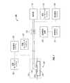
図1を参照すると、一実施例による組織部位105に減圧を適用する減圧治療システム100が示されている。組織部位105は、ヒト、動物、あるいはその他の生命体の、骨組織、脂肪組織、筋組織、皮膚組織、脈管組織、結合組織、軟骨、腱、靭帯、あるいはその他の組織を含む、身体組織である。組織部位105は、創傷、病変組織、あるいは欠損組織を含むが、この組織部位は、創傷、病変、あるいは欠損していない健康な組織であってもよい。組織部位105への減圧の適用は、組織部位105からの滲出液やその他の液体の排出の促進、並びに追加組織の成長の刺激に用いられる。組織部位105が創傷部位である場合、肉芽組織の成長と、滲出益とバクテリアの除去が、創傷の治癒を促進する。健康な組織を含む、非創傷あるいは非病変組織への減圧の適用も、採取して別の場所に移植された組織の成長を促進するのに用いられる。 Referring to FIG. 1, a reduced
組織部位105に適用される減圧は、減圧源110によってつくられる。減圧源110は、手動で、機械的に、あるいは電気的に作動するタイプのポンプである。減圧源110の非限定的な例には、保持されたエネルギィによって駆動するデバイスが含まれ、これで、減圧をつくることができる。このような保持エネルギィによる減圧源の例には、限定するものではないが、圧電エネルギィ、ばねエネルギィ、太陽エネルギィ、運動エネルギィ、コンデンサに蓄えられたエネルギィ、燃焼、及び、Sterlingによって開発されたあるいは同様のサイクルによって開発されたエネルギィ、によって駆動されるポンプが含まれる。減圧源110のその他の例は、ベローズポンプ、蠕動ポンプ、ダイアフラムポンプ、回転翼ポンプ、リニアピストンポンプ、空気ポンプ、水圧ポンプ、ハンドポンプ、フットポンプ、手動で作動するスプレーボトルを用いたポンプといった手動ポンプなどの手動で作動するデバイスを含む。減圧源110に用いることができるあるいはこれに含めることができるその他のデバイス及びプロセスには、シリンジ、リードねじ、ラッチ、ぜんまい仕掛けのデバイス、振り子で駆動するデバイス、手動発電機、浸透プロセス、加熱プロセス、及び、凝縮によって真空圧が発生するプロセスが含まれる。 The reduced pressure applied to the
別の実施例では、減圧源110は、化学反応によって駆動されるポンプを具えている。タブレット、溶液、スプレイ、あるいはその他の送達機構をポンプに送達して、化学反応を開始する。化学反応によって発生した熱を用いてポンプを駆動して減圧を生成する。別の実施例では、CO2シリンダなどの加圧ガスシリンダを用いて、ポンプを駆動して減圧を生成してる。更に別の実施例では、減圧源110が電池で駆動するポンプである。好ましくは、このポンプは少量の電力を使うポンプであり、電池の単回充電で長期間作動できるポンプである。In another embodiment, the reduced
減圧源110は、ドレッシング115を介して組織部位105に減圧を提供する。ドレッシング115は、マニフォールド120を具えており、これは、組織部位105近傍あるいは組織部位105に接触して配置することができる。マニフォールド120は、生体適合性の多孔質材であり、組織部位105に接触して配置して組織部位105に減圧を配分することができる。マニフォールド120は、フォーム、ガーゼ、フェルトマット、あるいは特定の生物学的アプリケーションに適したその他の材料で作ることができる。マニフォールド120は、複数のフローチャネルあるいは経路を具えており、組織部位105への減圧の配分あるいは組織部位105からの流体の配分を容易にする。 The reduced
一の実施例では、マニフォールド120は、多孔フォームであり、フローチャネルとして作用する複数の相互連結したセル又は孔を有する。多孔フォームは、ポリウレタン、開放セル、テキサス州サンアントニオ所在のKinetic Concepts,Inc.社によって製造されているGranuFoamなどの網状フォームであってもよい。開放セルフォームを用いる場合は、多孔率は変化するが、好ましくは約400乃至600ミクロンである。フローチャネルによって、開放セルを有するマニフォールド120の部分を通って液通する。このセルとフローチャネルは、形状及びサイズが均一であってもよく、あるいは、形状及びサイズがパターン化されたもの、あるいはランダムに変化するものを含む。マニフォールドのセル形状及びサイズの変化によってフローチャネルが変化し、このような特性を用いて、マニフォールド120を通る流体のフロー特性を変えることができる。 In one embodiment, the manifold 120 is a porous foam and has a plurality of interconnected cells or pores that act as flow channels. Porous foam is available from polyurethane, open cell, Kinetic Concepts, Inc., San Antonio, Texas. It may be a reticulated foam such as GranFooam manufactured by the company. When using open cell foam, the porosity varies but is preferably about 400 to 600 microns. A flow channel allows fluid to pass through the portion of the manifold 120 having open cells. The cells and flow channels may be uniform in shape and size, or may include those in which the shape and size are patterned, or those that vary randomly. Changes in the cell shape and size of the manifold change the flow channel, and such characteristics can be used to change the flow characteristics of the fluid through the
また、マニフォールド120は、減圧治療システム100の使用後に患者の身体から取り出す必要がない生体吸収性材料で構成することができる。好適な生体吸収性材料には、限定するものではないが、ポリ乳酸(PLA)とポリグリコール酸(PGA)のポリマーブレンドが含まれる。また、このポリマーブレンドには、限定するものではないが、ポリカーボネート、ポリフマル酸エステル、及びカプロラクトンが含まれる。更に、マニフォールド120は新しい細胞増殖の骨格として作用する、又は、骨格材料は、マニフォールド120と共働して用いて細胞増殖を促進する。骨格は、細胞の増殖あるいは組織形成を強化あるいは促進するのに使用される細胞増殖用テンプレートを提供する三次元多孔構造などの物質又は構造である。骨格材料の例には、リン酸カルシウム、コラーゲン、PLA/PGA、サンゴ−ヒドロキシアパタイト、カルボン酸、又は処理済み同種移植材が含まれる。一の例では、この骨格材料は、高空隙比を持つ(すなわち、空気含有量が多い)。 The manifold 120 can also be constructed of a bioabsorbable material that does not need to be removed from the patient's body after use of the reduced
ドレッシング115は、また、シーリング部材125を具える。マニフォールド120は、シーリング部材125を用いて組織部位105に固定される。シーリング部材125は、マニフォールド120を組織部位105に固定するのに使用するカバーであってもよい。シーリング部材125は、透過性あるいは半透過性であってもよいが、一の実施例では、シーリング部材125は、マニフォールド120にシーリング部材125を取り付けた後、組織部位105において減圧を維持することができる。シーリング部材125はシリコーンベースの化合物、アクリル材料、ヒドロゲル又はヒドロゲル形成材、あるいは、組織部位105に望まれる不透過性又は透過性特性を有するその他の生体適合性材料でできたドレープ又はフィルムであってもよい。シーリング部材125を疎水性材料で形成して、シーリング部材125による水分の吸収を防止するようにしてもよい。 The dressing 115 also includes a sealing
ドレープ形状などの「シート」形状で提供する代りに、シーリング部材125を注入可能なあるいはスプレィ可能な形状で提供でき、これはマニフォールド120を組織部位105に接触させ、配置した後にマニフォールド120の上に適用される。同様に、シーリング部材125はマニフォールド120と組織部位105の上に配置してシーリング機能を提供するデバイスを具えていてもよい。これには、限定するものではないが、吸引カップ、成型キャスト、ベル型ジャーが含まれる。 Instead of providing in a “sheet” shape, such as a drape shape, the sealing
一の実施例では、シーリング部材125は組織を囲むマニフォールド120と組織部位105と、気密連結を提供するように構成されている。気密連結は、シーリング部材125の周辺部に沿ってあるいはシーリング部材125のいずれかの部位に接着剤を配置して、シーリング部材125をマニフォールド120又は組織部位105の周辺組織に固定することによって、提供される。この接着剤は、シーリング部材125に予め設けておいてもよく、又は、シーリング部材125を取り付ける直前にシーリング部材125にスプレィ又は塗布するようにしてもよい。 In one embodiment, sealing
いくつかの場合は、組織部位105を密封するのにシーリング部材125は必要でない。例えば、組織部位105は、「自己密封」して、減圧を維持することができる。上皮組織あるいは深い組織創傷、窩洞、瘻孔の場合、シーリング部材125を使用することなく組織部位105における減圧の維持が可能である。組織はしばしばこれらのタイプの組織部位を包む、あるいは囲むため、組織部位を囲む組織は、シーリング部材として効果的に作動する。 In some cases, sealing
減圧源110によって生じる減圧は、送達チューブ135を用いて組織部位105に適用することができる。送達チューブ135は、気体、液体、ゲル、あるいはその他の流体が流れるものであればどのようなチューブでもよい。例えば、組織部位105からの滲出液が送達チューブ135を通って流れる。図1では、コネクタ150が送達チューブ135を流体回収装置140に連結している。しかしながら、送達チューブ135は、中間コネクタ150又は流体回収装置140を用いることなく、減圧源110をドレッシング115に直接連結することができる。 The reduced pressure generated by the reduced
送達チューブ135は、円形、楕円形、あるいは多角形といった断面形状を有している。また、送達チューブ135は、柔軟性のある又は柔軟性のない、どのような材料で作られていてもよい。また、送達チューブ135は、一又はそれ以上の流体が流れる経路あるいはルーメンを具える。例えば、送達チューブ135は二本のルーメンを有している。この例では、一方のルーメンは、組織部位105から流体回収装置140への滲出液の経路として使用することができる。他方のルーメンを用いて、空気、抗菌材、抗生物質、細胞増殖促進材、刺激流体、あるいはその他の化学的活性材、といった流体を組織部位105に送達するのに用いることができる。これらの流体がでてくる流体源は、図1に示されていない。 The
一の実施例では、送達チューブ135は、送達ルーメンと一又はそれ以上の回収ルーメンを具え、組織部位105からの滲出液を回収する。これらのルーメンは、各々、フィルタを具えており、ルーメンを通る滲出液の流れを管理することもできる。送達ルーメン、回収ルーメン、及び送達チューブ135に設けたフィルタの更なる詳細は、図2乃至10に提供されている。 In one embodiment,
一の実施例では、送達チューブ135は、連結部材145を介してマニフォールド120に連結されている。連結部材145によって、マニフォールド120から送達チューブ135への、及び逆の流体通路ができる。例えば、マニフォールド120を用いて組織部位105から回収した滲出液は、連結部材145を介して送達チューブ135へ入る。別の実施例では、減圧治療システム100は、連結部材145を具えていない。この実施例では、送達チューブ135をシーリング部材125内へ直接挿入する、又は、送達チューブ135の一端がマニフォールド120近傍にあるいはこれに接触するようにマニフォールド120に挿入することができる。 In one embodiment, the
減圧治療システム100は、流体回収装置140を具える。組織部位105からの滲出液などの液体は、送達チューブ135を通って流体回収装置140へ流れる。流体回収装置140は、気体や液体、並びに個体を含有する流体を収納できるデバイス又はキャビティであってもよい。例えば、流体回収装置140は、組織部位105からの滲出液を収納できる。送達チューブ135は、流体回収装置140に直接連結されているか、あるいは、コネクタ150などのコネクタを介して流体回収装置140に連結されている。 The reduced
流体回収装置140は、送達チューブ135によってマニフォールド120に流体連結された、フレキシブルなあるいは硬質のキャニスタ、バッグ、又はポーチである。流体回収装置140は、個別容器であってもよいし、減圧源110と動作可能に組み合わせて滲出液と流体を回収するようにしたものでもよい。ベローズポンプなどの手動ポンプが減圧源110として用いられている実施例では、減圧を生成する体積可変チャンバが流体回収装置140としても作用し、チャンバが膨張した時に流体を回収するようにしてもよい。流体回収装置140は、流体を回収する単一のチャンバを具えるものであってもよいし、代替的に、複数チャンバを有するものでもよい。乾燥材又は吸収材を流体回収装置140内に配置して、回収した流体を捕捉するあるいは制御することができる。流体回収装置140がない場合は、滲出液及びその他の流体を制御する方法を用いて、特に水溶性の流体がマニフォールド120から蒸発するようにしてもよい。別の実施例では、図2乃至10を参照して以下に述べる送達チューブ135内の一又はそれ以上の回収ルーメンを、流体回収装置140の代りに又はこれに加えて用いることができる。 The
減圧治療システム100は、減圧治療システム100のその他の構成要素と動作可能に関連する減圧フィードバックシステム155を具えており、減圧治療システム100のユーザに、組織部位105に送達されている又は減圧源110で発生している圧力の相対量あるいは絶対量を表示する情報を提供する。フィードバックシステムの例には、限定するものではないが、選択された値より減圧が上がったときに作動するポップバルブと、偏差ポップバルブが含まれる。ポップバルブ、特に、送達チューブ135内の減圧に相当する移動可能な表示器を具えるフィードバックシステムに関する更なる詳細を、図15乃至19を参照して以下に述べる。 The reduced
フィードバックシステムのその他の非限定的な例には、小型電池で給電する低電力電子式表示器、組織部位に適用されている特定の圧力を表示するダイヤル式表示器、様々な偏差特性を有するポリマ、及び、互いに対して移動して減圧源110で発生している相対圧力又は絶対圧力値を表示する可視識別子を生成するフィルム、が含まれる。「フィルム」ベースのシステムの一例は、減圧源110の第1部分に固定された黄色いフィルムであって、第2部分に固定された青いフィルムに対して相対的に移動可能なフィルムを具えている。この第1及び第2部分は、互いに対して相対的に移動して減圧を適用し、黄色いフィルムと青いフィルムが重なって緑の表示器をつくる。圧力が上がって、フィルムが互いから離れると、緑がなくなって、圧力が上がったことを表示する(すなわち、より多くの減圧を適用する必要がある)。 Other non-limiting examples of feedback systems include a low-power electronic indicator powered by a small battery, a dial indicator that displays a specific pressure applied to a tissue site, and a polymer with various deviation characteristics. And a film that moves relative to each other to generate a visual identifier that displays the relative pressure or absolute pressure value generated at the reduced
減圧治療システム100は更に、流体回収装置140内に存在する流体の量を検出する体積検出システム157と、組織部位105から回収した滲出液中の血液の存在を検出する血液検出システム159と、組織部位105の温度を監視する温度監視システム162と、組織部位105における炎症の存在を検出する炎症検出システム165と、及び/又は、組織部位105から回収した流体の流量をモニタする流量モニタリングシステム167を具える。炎症検出システム165は、バクテリアの存在により色が変化するフォーム又はその他の物質を具えていてもよい。このフォーム又はその他の物質は、マニフォールド120又は送達チューブ135に動作可能に取り付けられており、この色が変化する物質が組織部位105からの滲出液に露出する。上述した構成要素とシステムに加えて、減圧治療システム100は、バルブ、レギュレータ、スイッチ、及びその他の電気的構成要素、機械的構成要素、及び流体成分を具えており、組織部位105への減圧治療の提供を容易にしている。 The reduced
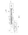
図2を参照すると、図1に示す減圧治療システム100の非限定的な例である減圧治療システム200が、実施例に従って示されている。一の実施例では、図1の流体回収装置140が、ドレッシング215と減圧源210との間に流体連結されたチューブ235である。ドレッシング215と減圧源210は、それぞれ、図1に示すドレッシング115と減圧源110の非限定的な例である。 Referring to FIG. 2, a reduced
チューブ235は複数のルーメンを具えている。特に、チューブ235は、送達ルーメン270と、複数の回収ルーメン272を具える。図2は、単一の送達ルーメン270と二本の回収ルーメン272を有するチューブ235を示しているが、チューブ235は、送達及び回収ルーメンを何本具えていてもよい。例えば、複数の送達ルーメンと単一の回収ルーメンがチューブ235に設けられていてもよい。 The
送達ルーメン270と複数の回収ルーメン272を含めて、チューブ235内の複数のルーメンのすべてが減圧源210に流体連結しており、すべてが減圧に露出される。このように、減圧源210で生成した減圧が、チューブ235内の複数のルーメンの各々を通って、ドレッシング215を介して組織部位205へ伝達される。一の実施例では、減圧源210が、送達ルーメン270と複数の回収ルーメン272を介して組織部位205へ減圧を適用して、複数の回収ルーメン272が、組織部位205から液体又は固体を含有する液体などの流体274を受ける。一例では、流体274は、組織部位205からの滲出液である。複数の回収ルーメン272は、組織部位205から受けた流体274を保持することができる。従って、図1に示す流体回収装置140などの、別体の流体回収装置が不要になる。 All of the plurality of lumens in the
減圧治療システム200は、チューブ235に連結された少なくとも一のフィルタを具えていてもよい。特に、チューブ235は、送達ルーメンフィルタ276と回収ルーメンフィルタ278を具える。送達ルーメンフィルタ276と回収ルーメンフィルタ278は、フィルタが配置されている一又はそれ以上の位置を組織部位205からの流体274が通過しないあるいは流れないようにする。送達ルーメンフィルタ276と回収ルーメンフィルタ278は、流体274の流れを防止できるものであれば、疎水性フィルタ、親水性フィルタ、及び機械的バルブなど、どのようなフィルタでもよい。送達ルーメンフィルタ276又は回収ルーメンフィルタ278が機械的バルブである例では、ダックビルバルブなどの一方向バルブを使用することができる。 The reduced
送達ルーメンフィルタ276は、組織部位205とドレッシング215の近傍にあるチューブ235の端部に連結されている。ここで用いられているように、「近傍」とは、別の物体位置、あるいは別の物体の近くを意味する。一例では、第1の物体が、第2の物体より特定の物体に対してより近くにある場合は、第1の物体は特定の物体に対して近傍にある。従って、チューブの第1の端部が組織部位205に対してチューブの第2の端部より近くにある場合は、チューブ235の第1の端部は組織部位205の近傍にある。送達ルーメンフィルタ276は、流体274がドレッシング215の一又はそれ以上の構成要素を通って送達ルーメン270に入るのを抑える又は防止している。したがって、流体274が複数の回収ルーメン272内に回収されている時でも、流体274に邪魔されることなく送達ルーメン270を介して連続的に減圧が適用される。
図2は、流体274が送達ルーメン270に入るのを防止している送達ルーメンフィルタ276を示す図であるが、送達ルーメンフィルタ276も、流体274が送達ルーメン270に沿った特定のポイントを通過しないように配置されている。例えば、送達ルーメンフィルタ276は、チューブ235の端部から特定の距離だけ離れて送達ルーメン270の内に配置されており、流体274は送達ルーメンフィルタ276に邪魔されることなく送達ルーメン270の一部に入ることができる。送達ルーメンフィルタ276の配置と連結に関する更なる詳細は、図4乃至6に提供されている。 FIG. 2 illustrates a
回収ルーメンフィルタ278は、減圧源210近傍にあるチューブ235の端部に連結されている。回収ルーメンフィルタ278は、流体274が減圧源210に入らないようにする、あるいは複数の回収ルーメン272から出ないようにしている。回収ルーメンフィルタ278の位置によっては、ドレッシング215と回収ルーメンフィルタ278との間の複数の回収ルーメン272は、組織部位205からの滲出液とその他の流体を受けることができるリザーバである。複数の回収ルーメン272は、減圧源210の影響を受けているので、組織部位205から、組織部位205近傍にあるマニフォールド220を通って、複数の回収ルーメン272へ流体が引き込まれる。流体用のスペースの体積は、複数の回収ルーメン272の直径と回収ルーメンの数、並びにドレッシング215と回収ルーメンフィルタ278間の各回収ルーメンの長さに依存する。例えば、複数の回収ルーメン272は、約30乃至60立方センチメートルの流体274を保持することができる。しかしながら、複数の回収ルーメン272の上述の物理的パラメータは、複数の回収ルーメン272がいかなる量の流体274でも保持できるような特別な実装に基づいて調整することができる。 The
複数の回収ルーメン272が流体で一杯になっても、複数の回収ルーメン272は続けて減圧源210から減圧を伝達することができる。複数の回収ルーメン272が、ドレッシング215と回収ルーメンフィルタ278の間で完全に流体274で一杯になると、減圧は複数の回収ルーメン272を通って伝達されなくなる。しかしながら、複数の回収ルーメン272が一杯になった後も、送達ルーメン270が減圧を伝達し続ける。 Even if the plurality of
回収ルーメンフィルタ278は、減圧源210近傍のチューブ235の端部に連結されたものが示されているが、回収ルーメンフィルタ278は、チューブ235に沿ったいずれの場所に配置されていてもよい。例えば、回収ルーメンフィルタ278は、チューブ235の長さに沿った中央に配置することができる。この例では、流体274が回収ルーメンフィルタ278によってチューブ235の中央で邪魔されるまで、複数の回収ルーメン272を流体274で満たすことができる。従って、回収ルーメンフィルタ278は、複数の回収ルーメン272に沿ったチューブ235の中央を流体274が通過しないようにする。この例では、複数の回収ルーメン272によって規定されたスペースの一部のみが、流体274で満たされる。 Although the
別の例では、減圧治療システム200が、複数の回収ルーメンフィルタを具えている。この例では、各回収ルーメンフィルタが、複数の回収ルーメン272の各回収ルーメンに沿って異なる位置に配置されている。従って、複数の回収ルーメン272の各回収ルーメンは、流体容量が異なる。 In another example, the reduced
減圧治療システム200は滲出液の少ない組織部位の治療に用いられるので、複数の回収ルーメン272によって提供されるより少ない流体回収量は(専用のキャニスタと反対に)、より長い時間で治療を提供する減圧治療システム200の能力にほとんど影響しないか、まったく影響しない。減圧送達チューブと一体化した流体回収装置のコンパクト性が、患者の不快感を最小にすると共に、患者の移動度を最大にする。治療中は、複数の回収ルーメン272が流体274で完全に一杯になると、チューブ235を新しいチューブと容易に交換することができる。 Because the reduced
チューブを交換する間に流体がこぼれる、あるいは治療中に流体がマニフォールド220に逆流するリスクを最小限にするために、複数の回収ルーメン272を乾燥材、吸収材、あるいはその他のトラッピング材で部分的に満たすあるいはこれをパッキングしておくことができる。このような吸収材及び/又はトラッピング特性を有する送達チューブの非限定的な実施例が、図10乃至14に示されている。 In order to minimize the risk of fluid spilling during tube changes or the flow of fluid back to the manifold 220 during treatment, the
図2では、複数の回収ルーメン272の流体274を含有する部分に影が付けられており、流体274が減圧治療システム200のユーザに可視であることを示している。チューブ235は、少なくとも一の実質的に透明なチューブ部分を具えており、これを通して流体274を見ることができる。例えば、一又はそれ以上の実質的に透明なチューブ部分は、透明材料でできたチューブ235上の窓である。これらの各窓は、各回収ルーメン272近傍にあるチューブ235の部分の上に延在していてもよい。 In FIG. 2, portions of the plurality of
別の例では、チューブ235を透明材料で作ってもよい。このように、チューブ235の全体が透明であるため、流体274が可視である。例えば、滲出液などの組織部位205からの流体274は暗色をしているので、複数の回収ルーメン272内の流体レベルを、ユーザが容易に確かめることができる。 In another example, the
チューブ235は、区割280を具えていてもよい。区割280は、複数の回収ルーメン272内の流体274の量を表示する。チューブ235が、透明窓などの一又はそれ以上の実質的に透明なチューブ部分を具えている例では、区割280を各窓に沿って設けることができる。各区割280は、流体274の特定の体積又は量に対応している。例えば、第1の区割280には、「5cc」のラベルが付されており、それ以降の各区割には、5立方センチメートルの増加分でラベルが付されている。特定の増加分の使用は、実装による。 The
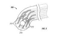
図3を参照すると、図2に示す斜視断面表示3から見たチューブ300の断面図が示されている。図3に示すように、送達ルーメン270は、各回収ルーメン272より断面が大きい。しかしながら、一例では、送達ルーメン270の断面が、各回収ルーメン272の断面と同じか、それより小さい。送達ルーメン270と回収ルーメン272はまた、丸い断面形状を有している。しかしながら、送達ルーメン270と回収ルーメン272は、楕円形、多角形、あるいは不規則な断面形状など、どのような断面形状を有していてもよい。 Referring to FIG. 3, a cross-sectional view of the
各回収ルーメン272は、回収ルーメン272が円形パターンで送達ルーメン270を囲むように送達ルーメン270から等距離に示されている。しかしながら、送達ルーメン270と回収ルーメン272は、各回収ルーメン272が送達ルーメン270から異なる距離にあることを含めて、互いに対してどのような空間的構造を有していてもよい。更に、チューブ300は送達ルーメン270のような、二又はそれ以上の送達ルーメンを具えていてもよい。任意数の回収ルーメン272がチューブ300に含まれていてもよい。一例では、チューブ300内の送達ルーメンの数が、回収ルーメンの数を超えている。 Each
送達ルーメン270は、チューブ300の長手方向中央ラインに沿って配置されたものが示されている。しかしながら、送達ルーメン270は、チューブ300の長さにわたる任意の縦軸に沿って配置するようにしてもよい。一例では、送達ルーメン270と回収ルーメン272は、チューブ300の長さにわたって縦方向に延在する壁によって規定されている。この例では、二又はそれ以上の交差壁が四分円を規定しており、いずれもが、送達ルーメン又は回収ルーメンでありうる。
ここで、図4を参照すると、図2の斜視断面表示4から見たチューブ400の断面図が示されている。チューブ400は、送達ルーメン270の開口においてチューブ400に連結されている送達ルーメンフィルタ276を具える。送達ルーメンフィルタ276は、送達ルーメン270と同じかあるいは若干大きい断面を具えており、送達ルーメンフィルタ276によって流体が送達ルーメン270に確実に入らないようにしている。送達ルーメンフィルタ276は、いずれかの方法を用いてチューブ400の端部に連結することができる。例えば、送達ルーメンフィルタ276をチューブ400の端部に、溶接、ねじどめ、のり付け、ボルト止め、エアロックシール、スナップ止め、あるいはプレスすることができる。 Referring now to FIG. 4, a cross-sectional view of the
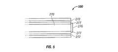
図5を参照すると、図4の斜視案面表示5から見たチューブ500の断面図が示されている。図5は、送達ルーメン270の開口が送達ルーメンフィルタ276によって邪魔されて、組織部位からの流体が送達ルーメン270に入れない状態を示している。特に、送達ルーメンフィルタ276は、送達ルーメン270の直ぐ外側に配置されており、突出部分277において、送達ルーメン270の径に送達ルーメンフィルタ276が突出している。送達ルーメンフィルタ276は、流体が送達ルーメン270に流れ込まないように十分な厚さを有する。回収ルーメン272の開口は、送達ルーメンフィルタ276によって塞がれておらず、回収ルーメン272は流体を受けて回収できる。 Referring to FIG. 5, a cross-sectional view of the
図6を参照すると、チューブ600の断面図が示されており、ここでは、送達ルーメンフィルタ276が、図5に示す送達ルーメンフィルタ276と異なるサイズと構造を有する。特に、送達ルーメンフィルタ276は送達ルーメン270の直径とほぼ同じ直径を有し、送達ルーメン270によって規定されたスペースに送達ルーメンフィルタ276がフィットしている。送達ルーメンフィルタ276は送達ルーメン270の端部に配置されているが、送達ルーメンフィルタ276は送達ルーメン270の長さに沿ったいずれの個所に配置してもよい。この例では、送達ルーメンフィルタ276によって、送達ルーメンフィルタ276が送達ルーメン270に沿って配置されている位置を組織部位からの流体が通過しないようになっている。 Referring to FIG. 6, a cross-sectional view of a
図7を参照すると、図2に示す斜視断面表示7からみたチューブ700の断面が示されている。チューブ700は、回収ルーメンフィルタ278を具える。回収ルーメンフィルタ278は、チューブ700の端部に連結されて示されている。また、チューブ700の端部から切り離して回収ルーメンフィルタ278が示されており、回収ルーメンフィルタの形状がよりわかるようにしている。回収ルーメンフィルタ278は、開口279を有するディスクである。チューブ700の端部に連結するときに、回収ルーメンフィルタ278は、回収ルーメン272を覆っているが、送達ルーメン270は覆っておらず、開口279が送達ルーメン270の開口にある。従って、回収ルーメンフィルタ278は、回収ルーメンフィルタ278によって回収された流体が、回収ルーメン272から出て行かないようにするとともに、図2に示す減圧源210などの減圧源に入らないようにする。しかしながら、減圧は回収ルーメンフィルタ278を通って適用され、回収ルーメン272は組織部位に減圧を伝達できる。回収ルーメンフィルタ278は、「O」字型のものが示されているが、回収ルーメンフィルタ278は一又はそれ以上の回収ルーメン272から流体が出て行くのを防げるものであれば、どのような形でもよい。例えば、気体は送達ルーメン270から出て行くことができるので、回収ルーメンフィルタ278は中央孔を持たないディスクでもよい。 Referring to FIG. 7, a cross section of the
回収ルーメンフィルタ278は、任意の方法を用いてチューブ700の端部に連結することができる。例えば、回収ルーメンフィルタ278は、チューブ700の端部に、溶接、ねじどめ、のり付け、ボルト止め、エアロックシール、スナップ止め、あるいはプレスすることができる。 The
図8を参照すると、図7に断面斜視表示8から見たチューブ800の断面図が示されている。図8は、回収ルーメン272の開口が回収ルーメンフィルタ278によって塞がれており、組織部位からの流体が回収ルーメン272から出ることができない、又は減圧源に入ることができない状態を示す。特に、回収ルーメンフィルタ278は、回収ルーメン272のすぐ外側に配置されており、回収ルーメンフィルタ278が各回収ルーメン272の各径に突出して示されている。回収ルーメンフィルタ278は、回収ルーメンフィルタ278の外に流体が流れないようにするのに十分な厚さを有している。送達ルーメン270の開口は、回収ルーメンフィルタ278によって塞がれておらず、送達ルーメン270の開口と減圧源との間には障害物がない。 Referring to FIG. 8, a cross-sectional view of the
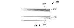
図9を参照すると、チューブ900の断面が示されており、ここでは、回収ルーメンフィルタ278が、図8に示す回収ルーメンフィルタ278とは異なるサイズと構成を有する。特に、回収ルーメンフィルタ278は複数の回収ルーメンフィルタを具えており、この各フィルタが回収ルーメン272によって規定されるスペース内部に配置されている。各回収ルーメンフィルタ278の径は、各回収ルーメン272の径とほぼ同じであり、回収ルーメンフィルタ278が回収ルーメン272にフィットするようになっている。この例では、各回収ルーメンフィルタが機械的なバルブであり、滲出液などの流体の流れを防止するが気体の流れは防止しないため、回収ルーメンフィルタ278に減圧が流れるようになっている。回収ルーメンフィルタ278は各回収ルーメン272の端部に配置されているが、回収ルーメンフィルタ278は回収ルーメン272の長さに沿ったどの位置に配置してもよく、これによって各回収ルーメン272の流体容量が決まる。回収ルーメンフィルタ278の各々は、各回収ルーメン272に沿って異なる位置に配置されており、従って各回収ルーメン272の流体容量は異なる。 Referring to FIG. 9, a cross section of a
図10及び11を参照すると、一実施例による送達チューブ1000が示されている。特に、図10は、送達チューブ1000の一部を破線で示した斜視図である。図11は、図10の11−11線に沿った送達チューブ1000の断面図である。送達チューブ1000は、図1の送達チューブ135や図2のチューブ235と別の非限定的な実施例である。送達チューブ1000は、ルーメン1010を具えており、図1に示す減圧源110などの減圧源からの減圧を、図1に示す組織部位105などの組織部位に伝達するよう動作可能である。送達チューブ1000は、また、組織部位からの液体を受けるようにも動作可能である。特に、送達チューブ1000を通って伝達された減圧は、組織部位からの液体をルーメン1010に吸い込ませる。一実施例では、図1に示すドレッシング115などのドレッシングを通っても減圧が伝達され、図1に示すマニフォールド120や連結部材145などのドレッシングの構成部品を介して、送達チューブ1000に液体が入る。図10及び11は、単一ルーメン1010を有する送達チューブ1000を示しているが、送達チューブ1000は、ルーメン1010などのルーメンを任意数具えていてもよい。 Referring to FIGS. 10 and 11, a
ルーメン1010は溝1015を具えており、この溝がルーメン1010の内側面に細長い刻み目を形成している。溝1015は、送達チューブ1000の長さの少なくとも一部に沿って延在している。別の実施例では、溝1015は、送達チューブ1000の全長に沿って延在している。各溝1015の壁は、ほぼ半円の断面形状を有する。しかしながら、いずれかの溝1015の壁の断面形状は、多角形、楕円形、不規則形状など、どのような形でもよい。一例では、溝1015の壁の断面形状が変化して、送達チューブ1000の吸収容量を調整するようにしてもよい。
ルーメン1010は、リブ1020を具えている。溝1015は、少なくとも一のリブ1020によって互いに分離されている。図10及び11は、6本の溝1015と6つのリブ1020を有するルーメン1010を示しているが、ルーメン1010は、任意数のルーメンとリブを具えていてもよい。例えば、溝の数を変更して、送達チューブ1000の流体保持容量と吸収特性を調整することができる。
送達チューブ1000は、吸収材1025を具えていてもよい。吸収材1025は、ルーメン1010内に配置されている。吸収材1025は、滲出液などの組織部位からの液体を吸収して保持するよう動作可能である。吸収材の非限定的な例には、高吸収繊維/粒子、ハイドロファイバー、カルボキシルメチルセルロースナトリウム、及び、アルギン酸塩が含まれる。吸収材1025は、ルーメン1010の内側面を少なくとも部分的に覆っている。別の実施例では、吸収材1025は、ルーメン1010の内側面全体を覆っている。
別の実施例では、吸収材1025が、溝1015全体にあるいは一部に配置されている。例えば、吸収材1025は各溝1015の内側面を覆っている。この実施例では、吸収材1025は、リブ1020を覆っている。各溝1015の内側面を含めて、ルーメン1010の内側面全体あるいは一部を覆うのに用いる吸収材1025の量を変化させて、送達チューブ1000の吸収容量を増やすあるいは減らすことができる。 In another embodiment, the
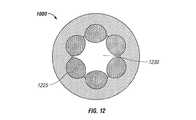
図12を参照すると、図10における12−12線に沿った送達チューブ1000の断面が示されている。特に、図12は、送達チューブ1000の一部を示しており、ここでは、吸収材1025が組織部位からの液体で飽和して、飽和吸収材1225を形成している。飽和吸収材1225は、滲出液などの組織部位からの液体を保持することができる。送達チューブ1000は、中央に減圧経路1230を具えており、吸収材が組織部位からの液体で飽和している場合でも、この経路が残る。従って、送達チューブ1000は、ルーメン1010内の吸収材の全部あるいは一部が液体で飽和した場合でも、減圧を伝達し続けることができる。 Referring to FIG. 12, a cross-section of
図13及び14を参照すると、一実施例による送達チューブ1300が示されている。特に、図13は、送達チューブ1300の一部を取り出して示す斜視図である。図14は、図13の14−14線に沿った送達チューブ1300の断面図である。送達チューブ1300は、図1に示す送達チューブ135又は図2に示すチューブ235の別の非限定的な実施例である。 Referring to FIGS. 13 and 14, a
送達チューブ1300は、ルーメン1410を具えており、これは、図10に示すルーメン1010の非限定的な例である。ルーメン1410は、吸収コア1325を具える。吸収コア1325は、組織部位からの液体を吸収するよう動作可能である。一の実施例では、吸収コア1325は、組織部位からの液体を吸収すると膨張する。一の実施例では、吸収コア1325は、図10及び11に示す吸収材1025と同じ又は同様の材料でできている。別の実施例では、吸収コア1325は、吸収材を含むフォーム材であり、図10及び11に示す吸収材1025と同じ又は同様の材料を具えている。吸収コア1325は、ポリビニルアルコールなどの水溶性ポリマで作ってもよい。 The
送達チューブ1300が、ほぼ真っ直ぐである場合、吸収コア1325はほぼ円筒形状をしている。吸収コア1325は、図14に示すように、実質的に断面円形をしている。送達チューブ1300と吸収コア1325はフレキシブルなので、ほぼ円筒状の吸収コア1325は様々な方向に曲げることができる。 When the
ルーメン1410は、溝1316及び1318を具えており、これらは図10及び11の溝1015の非限定的な例である。図13及び14の例では、滲出液などの液体が溝1318に含まれている。逆に、溝1316には、液体は含まれていない。一の実施例では、溝1316及び1318は、ギャップ1340などのギャップを介して互いに液通している。この実施例では、液体は溝1316及び1318のいずれにも流れる。溝1316と1318の存在によって、減圧が伝達される開通路を確実に維持するようにしている。送達チューブ1300を曲げることができるあるいは柔軟である場合にこのような開通路を維持することができる。ルーメン1410のその他の断面形状を用いても、このような開通路を確保することができる。
一の実施例では、溝1316は、減圧源から減圧を送達する減圧送達溝であり、この実施例では、溝1318は組織部位からの液体を保持する回収溝である。総溝数のうち任意数の減圧溝と任意数の回収溝がある。また、一の実施例では、溝1316と1318の一方又は双方が、図11に示す吸収材1025などの吸収材で被覆されていてもよい。吸収コア1325の外側面1327も、吸収材で被覆するようにしてもよい。 In one example, the
別の実施例では、吸収コア1325の外側面1327とリブ1320との間が直接接触していることによって各溝1316と1318の間の液通が防止されている。この実施例では、吸収コア1325が液体を吸収した後に膨張すると、一の溝から他の溝へ液体が流れなくなるようになっている。別の実施例では、壁、膜、あるはその他の部材で吸収コア1325の外側面1327を各リブ1320a及び1320bに連結して、溝1318から溝1316へ液体が通過できないようになっている。この実施例では、溝1316が減圧送達溝であり、送達チューブ1300によって吸収された液体の量に関係なく、常に減圧を伝達することができる。又、この実施例では、図2に示す送達ルーメンフィルタ276などのフィルタを組織部位近傍の送達チューブ1300の端部に配置して、組織部位からの液体が溝1316に入らないようにしている。例えば、このフィルタは、組織部位近傍の送達チューブ1300の端部の上の溝1316の入口を覆っている。 In another embodiment, direct contact between the
別の実施例では、吸収コア1325が送達チューブ1300へ引きこまれた液体を吸収することができ、溝1316にも1318にも液体が含まれないようにしている。この実施例では、吸収コア1325が液体で飽和すると、溝1316と1318のいずれかが液体を回収し始める。この実施例では、吸収コア1325が吸収容量がまだある間は、溝1316と1318のすべてが組織部位に減圧を伝達するようにしてもよい。別の実施例では、ルーメン1410が溝を有しておらず、ほぼ円形の断面形状を有するようにしてもよい。 In another embodiment, the
吸収コア1325は、ルーメン1410内で移動可能であってもよい。例えば、吸収コア1325は、多方向矢印1345によって示すように、その方向に移動することができる。従って、溝1316と1318の各々が互いに液通している場合は、送達チューブ1300が柔軟であるときの吸収コア1325の動きが、溝間の液体の移動を容易にすると共に、減圧の伝達も容易にする。
一の実施例では、いずれかの実施例の記載されているように、組織部位からの液体を保持する方法が組織部位と液通している送達チューブを配置するステップを具える。この方法は、また、送達チューブの少なくとも一のルーメンに減圧を供給して、組織部位からの液体を当該少なくとも一のルーメンに引き込むステップを具える。この方法は、また、この少なくとも一のルーメン内の吸収材を用いて組織からの液体を吸収して、組織部位からの液体をこの少なくとも一のルーメンに保持するステップを具える。一の実施例では、この方法はまた、図1に示すマニフォールド120などのマニフォールドを組織部位に適用するステップを具える。この実施例では、組織部位と液通する送達チューブを配置するステップが、マニフォールドを介して組織部位と液通する送達チューブを配置するステップを具える。 In one embodiment, as described in any of the embodiments, a method for retaining fluid from a tissue site includes positioning a delivery tube in fluid communication with the tissue site. The method also includes providing a vacuum to at least one lumen of the delivery tube to draw liquid from the tissue site into the at least one lumen. The method also includes absorbing fluid from the tissue using an absorbent material in the at least one lumen to retain fluid from the tissue site in the at least one lumen. In one embodiment, the method also includes applying a manifold, such as
一の実施例では、組織部位からの液体を保持する送達チューブを製造する方法が、少なくとも一のルーメンを有する送達チューブを形成するステップを具える。この方法で形成した送達チューブは、図に示すいずれかの実施例によるものである。この方法は、また、ルーメン内に吸収材を提供するステップを具える。この吸収材は、組織部位から滲出液などの液体を吸収するように動作可能である。この方法は、また、図10に示す吸収材1025などの吸収材を、少なくとも一のルーメンに適用するステップを具える。一の実施例では、吸収材は、図13に示す吸収コア1325などの吸収コアである。別の実施例では、少なくとも一のルーメンに吸収材を適用するステップが、少なくとも一のルーメンの内側面の少なくとも一部を吸収材でコーティングするステップを具えている。 In one embodiment, a method of manufacturing a delivery tube that retains liquid from a tissue site includes forming a delivery tube having at least one lumen. The delivery tube formed in this way is according to any of the examples shown in the figures. The method also includes providing an absorbent material within the lumen. The absorbent material is operable to absorb liquid such as exudate from the tissue site. The method also includes applying an absorbent material, such as
図15を参照すると、図1に示す減圧治療システム100の非限定的な例である減圧治療システム1500が実施例に従って示されている。特に、減圧治療システム1500は、図1に示す減圧フィードバックシステム155の非限定的な例を含む。減圧治療システム1500は減圧源1510を具え、これは、組織部位1505に適用される減圧を生成する。 Referring to FIG. 15, a reduced
減圧治療システム1500は、また、送達チューブ1535の二つの部分間に配置された表示器ハウジング1585を具える。送達チューブ1535は、図1に示す送達チューブ135の非限定的な例である。表示器ハウジング1585は、連結部分1586を具える。連結部分1586は、送達チューブ1535の一の部分から、送達チューブ1535の別の部分へ減圧を伝達する。連結部分1586は、また、送達チューブ1535に含まれる減圧と同量あるいは同じような量の減圧を含む。表示器ハウジング1585は表示器1588を具えており、これは、表示器ハウジング1585のチューブ部分1590に沿った開口に摺動可能に連結されている。表示器1588は、円筒形状を有していてもよい。表示器1588は、また、楕円形又は多角形の断面形状を有していてもよい。表示器1588は、赤、オレンジ、黄色などどのような色であってもよい。 The reduced
表示器1588は、減圧治療システム1500に存在するある量の減圧に応答して、所望の又は治療量の減圧が組織部位1505に適用されているかどうかをユーザが決定することができるようになっている。特に、表示器1588は、軸1592に沿った複数位置に移動可能である。この複数の位置には、引っ込んだ位置が含まれている。引っ込んだ位置において、表示器1588は、チューブ部分1590内に完全にあるいは部分的に引き込まれて、表示器1588をユーザが部分的にあるいは完全に見ることができなくなる。複数の位置は、延長した位置を具えていてもよい。図15では、表示器1588が延長位置にある状態が示されている。延長位置においては、表示器1588は完全に、あるいは部分的にチューブ位置1590から突出しており、ユーザが表示器1588を見ることができる。複数の位置は、完全に延長した位置と完全に引っ込んだ位置との間の任意の位置を具えていてもよい。
減圧治療システム1500は、また、表示器1588に連結されて、チューブ位置1590に配置されたスプリングなどの圧縮部材を具えている。図15には圧縮部材は示されていないが、図16及び17において以下に詳細に述べる。圧縮部材は表示器1588にバイアス力をかけて、表示器1588を延長位置に向けてバイアスする。このバイアス力は、矢印1593で示す方向にかかる。 The reduced
表示器ハウジング1585は、送達チューブ1535の二つの部分間に配置されたものが示されているが、組織部位1505に適用されている減圧が検出できるところであれば、表示器ハウジング1585は減圧治療システム1500のどこに配置してもよい。例えば、表示器ハウジング1585は、表示器1588と共にシーリング部材1525又は連結器1545を含むドレッシング1515のどこに配置してもよい。破線で示す表示器1594は、表示器1588と共に、表示器ハウジング1585がシーリング部材1525の上に配置されている例を示す。別の例では、減圧源1510をドレッシング1515に連結している単一の送達チューブの一方の端部に、表示器1588と共に表示器ハウジング1585を配置することができる。 The
一の実施例では、表示器1588が、減圧源1510からの減圧が存在して、引っ込んだ位置に移動している。特に、表示器1588は、送達チューブ1535と連結部分1586に減圧が存在するときに、引っ込んだ位置に移動する。引っ込んだ位置に移動する際に、表示器1588は、矢印1593によって表示される方向に圧縮部材によってかかっているバイアス力に打ち勝たなくてはならない。連結部分1586内の十分に高い減圧によって、このバイアス力に打ち勝って、表示器1588を引っ込んだ位置に引っ張ることができる。このバイアス力に打ち勝つのに必要な量の減圧は、圧縮部材によってかかるバイアス量に依存する。圧縮部材がコイルばねであるこの例では、コイルばねのばね定数によって、表示器1588を引っ込んだ位置に引っ張るのに必要な減圧の量が決まる。 In one embodiment, the
一の例では、送達チューブ1535内の減圧が第1のスレッシュホールド減圧を超えると、表示器1588は引っ込んだ位置に移動する。この第1のスレッシュホールド減圧はユーザが決めることができ、圧縮部材によってかかるバイアス力を変化させることによって実装することができる。例えば、ユーザは、表示器1588を引っ込んだ位置に引っ張るために、送達チューブ1535の減圧が治療用減圧を超えるのに必要なばね定数を有する圧縮部材を選択することができる。一の実施例では、減圧源によって生じるゲージ圧が、約−125水銀柱mmと同じかこれより低くなると、表示器1588が引っ込んだ位置に移動する。このように、減圧治療システム1500のユーザは、表示器1588がチューブ位置1590から突出していないことを観察することによって、治療用減圧が組織部位1505に適応されていることを視覚的に検出することができる。 In one example, when the reduced pressure in the
別の実施例では、送達チューブ1535の減圧が第2のスレッシュホールド減圧より低い時に、圧縮部材が表示器1588を延長位置にバイアスする。一例では、第1のスレッシュホールド減圧が、第2のスレッシュホールド減圧と同じである。別の例では、第1のスレッシュホールド減圧が第2のスレッシュホールド減圧と異なっており、減圧が第1のスレッシュホールド減圧を超えると表示器が完全に引っ込んだ位置になり、減圧が第2のスレッシュホールド減圧より低いと完全に延長した位置になる。この実施例では、減圧が第1及び第2のスレッシュホールド減圧の間にあるときは、表示器1588は完全に引っ込んだ位置と完全に延長した位置の中間位置にある。 In another embodiment, the compression member biases the
別の実施例では、送達チューブ1535に減圧がない時に、圧縮部材が表示器1588を延長した位置にバイアスする。一例では、減圧がないのは減圧源1510のスイッチが切れているためである。減圧がないか、スレッシュホールド減圧より低いと、チューブ位置1590における圧縮部材が表示器1588をバイアスしてチューブ位置1590から突出させ、表示器1588がチューブ位置1590から突出していることを観察することによって、治療用減圧が組織部位1505に適用されていないことをユーザが視覚的に検出することができる。したがって、ユーザは組織部位1505に治療用減圧を適用するのに必要な動作を行うことができる。送達チューブ1535内の減圧がない、あるいはスレッシュホールド減圧より低い一つの理由は、送達チューブ1535内に、あるいは減圧治療システム1500のどこかに漏れがあるためである。この状況では、表示器1588が延長した位置にあるときにあり得る漏れに対してユーザが警告を受ける。 In another example, the compression member biases the
図16を参照すると、図15に示すような減圧フィードバックシステム1600が、実施例に従って示されている。特に、表示器1588は、減圧フィードバックシステム1600において延長した位置にある。 Referring to FIG. 16, a reduced
連結部分1586は、送達チューブ1535の二つの部分に摺動可能に係合して密封フィットを形成している。表示器ハウジング1585の連結部分1586も、様々な方法で、送達チューブ1535の二つの部分に密封係合することができる。例えば、連結部分1586は、送達チューブ1535の二つの部分に、溶接、ねじ止め、のり付け、ボルト止め、エアーロック密封、あるいはスナップ止めをすることができる。 The connecting
減圧フィードバックシステム1600では圧縮部材がコイルばねである。表示器ハウジング1585のチューブ部分1590はベース1596を具えており、このベースにコイルばね1595の一端が連結されている。しかし、コイルばね1595のこの端部は表示器1588には取り付けられておらず、コイルばねを用いて表示器1588にバイアス力をかける表示器ハウジングの別の部分に取り付けることができる。チューブ部分1590の内側面は筒状開口であり、これに沿って表示器1588が引っ込んだ位置及び延長した位置にスライドすることができる。コイルばね1595は、筒状壁の一部を形成している複数の波形部分1597によって保持されている。波形部分1597によって、チューブ部分1590の内側壁に横方向の応力が生じることなく、筒状壁が圧縮され、膨張する。 In the
減圧フィードバックシステム1600は、また、キャップ1598を具えている。キャップ1598は、透明材料でできており、これによって、表示器1588が延長した位置にあるときに、ユーザが表示器1588を見ることができる。一例では、キャップ1598も表示器ハウジング1585の残りの部分に密封係合されており、減圧が表示器ハウジング1585の筒状開口を通って逃げて行かないようにしている。 The reduced
上述したように、コイルばね1595は、どのようなばね定数を有していてもよい。コイルばね1595のばね定数が、延長した位置に向けて表示器1588に力をかけるバイアス力を決める。一の実施例では、コイルばね1595が、送達チューブ1535内のゲージ圧が約−125水銀柱mmを超える時に、延長した位置に表示器1588をバイアスするようなばね定数を、コイルばね1595が有している。その他のばね定数を有するその他のコイルばねを用いて、送達チューブ1535内の絶対圧力が、所望の治療用減圧スレッシュホールドなどその他の全体圧力スレッシュホールドを超えると、表示器1588を延長した位置にバイアスするようにしてもよい。 As described above, the
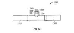
図17を参照すると、減圧フィードバックシステム1600の非限定的な実施例である減圧フィードバックシステム1700が実施例に従って示されている。特に、減圧フィードバックシステム1700は、引っ込んだ位置にある表示器1588を示している。表示器1588が引っ込んだ位置にあるとき、送達チューブ1535からの減圧が、波形部分1597で形成された筒状壁を通って表示器1588に伝達される。この減圧が、表示器1588に、コイルばね1595によって対向する方向にかかるバイアス力に打ち勝つに十分な引張力をかける。このように、表示器1588は透明なキャップ1598の外に引っ張られ、減圧治療システムのユーザの視界から外れる。表示器1588がキャップ1598から見えなくなるということは、治療用圧力が組織部位に与えられていることをユーザに示している。別の実施例では、キャップ1598は、表示器1588が引っ込んだ位置にあるときにキャップ1598もチューブ部分1590内に引っ込むように、表示器1588に連結されている。 Referring to FIG. 17, a reduced
図18を参照すると、図15に示す減圧フィードバックシステムの非限定的な実施例である減圧フィードバックシステム1800が、実施例に従って示されている。図18に示す斜視図は、表示器1588と、キャップ1598と、チューブ部分1590、並びに表示器1588が突出している開口1599の円形断面図である。しかしながら、これらの構成部品は、楕円形、多角形などどの様な断面であってもよい。 Referring to FIG. 18, a reduced
図19を参照すると、送達チューブ1535における減圧と、表示器1588の位置(図15に示す)との間の関係を示すグラフが、実施例に従って示されている。グラフ1900に示すように、送達チューブ1535における減圧が増えると、表示器1588が完全に引っ込んだ位置に移動する。一の実施例では、表示器1588は、グラフライン1910で表示するように完全に引っ込んだ位置に向けて直線状に移動する。減圧と表示器1588の位置間の関係は、グラフライン1915と1920で示すように、その他のパターンをとってもよい。階段状パターンなどのその他のパターンも、減圧と表示器1588の位置間の関係を特徴づけている。一例では、表示器1588は、減圧が125水銀柱mmの絶対圧力に対応しているときに、完全に引っ込んだ位置にある。 Referring to FIG. 19, a graph illustrating the relationship between the reduced pressure in the
図20を参照すると、図2に示す減圧治療システム200などの減圧治療システムが実装されているプロセスが、実施例に従って示されている。このプロセスは、送達チューブ内の複数のルーメンを介して組織部位に減圧を提供する(ステップ2005)。このプロセスは、複数ルーメン中の少なくとも一の回収ルーメン内に、組織部位からの流体を保持する(ステップ2010)。このプロセスは、送達チューブ上の複数の区割に基づいて少なくとも一の回収ルーメン内の流体の流体レベルを決定する(ステップ2015)。 Referring to FIG. 20, a process in which a reduced pressure treatment system such as the reduced
図21を参照すると、図10に示す減圧治療システム1000などの減圧治療システムが実装されているプロセスが、実施例に従って示されている。このプロセスは、減圧源を用いて組織部位に減圧を適用する(ステップ2105)。このプロセスは、送達チューブ又は減圧治療システムのその他の構成要素内にスレッシュホールド量の減圧が存在するか否かを決定する(ステップ2110)。このプロセスが、スレッシュホールド量の減圧が存在しないと決定すると、圧縮部材を用いて表示器を延長した位置に移動させる。次いで、このプロセスはステップ2105に戻る。ステップ2110に戻って、プロセスがスレッシュホールド量の減圧が存在すると決定すると、表示器を引っ込んだ位置に移動させる(ステップ2120)。 Referring to FIG. 21, a process in which a reduced pressure treatment system such as the reduced
図に示す様々な実施例におけるフローチャートとブロック図は、本装置と方法のいくつかのありうる実装例の構造、機能及び動作を示している。いくつかの代替の実装例では、ブロックに示される機能が、図に示す順番でなく生じていてもよい。例えば、いくつかの場合では、連続して示されている二つのブロックがほぼ同時に行われてもよく、あるいは、このブロックは関連する機能によっては、逆の順番で実行することもできる。
The flowcharts and block diagrams in the various embodiments illustrated in the figures illustrate the structure, functionality, and operation of some possible implementations of the present apparatus and method. In some alternative implementations, the functions shown in the blocks may occur out of the order shown. For example, in some cases, two blocks shown in succession may be performed substantially simultaneously, or the blocks may be executed in reverse order depending on the functions involved.
Claims (1)
Translated fromJapanese減圧を供給するように動作可能な減圧源と;
前記減圧を配分するように構成されたマニフォールドと;
ルーメンを有する送達チューブであって、前記減圧源から前記マニフォールドへ前記減圧を伝送するように動作可能であり、前記マニフォールドを介して前記組織部位からの液体を受け取るように動作可能な送達チューブと;
前記ルーメンの少なくとも一部に配置され、前記組織部位からの液体を吸収するように動作可能な吸収材と;を具え、
前記ルーメンが当該吸収材を有する部分と、吸収材を有していない部分とを具えることを特徴とするシステム。
In a system for retaining fluid from a tissue site, the system:
A reduced pressure source operable to supply reduced pressure;
A manifold configured to distribute the reduced pressure;
A delivery tube having a lumen, operable to transmit the reduced pressure from the reduced pressure source to the manifold, and operable to receive fluid from the tissue site via the manifold;
An absorbent material disposed on at least a portion of the lumen and operable to absorb liquid from the tissue site;
A system wherein the lumen comprises a portion having the absorbent material and a portion not having the absorbent material.
Applications Claiming Priority (2)
| Application Number | Priority Date | Filing Date | Title |
|---|---|---|---|
| US12/275,417US8267908B2 (en) | 2007-02-09 | 2008-11-21 | Delivery tube, system, and method for storing liquid from a tissue site |
| US12/275,417 | 2008-11-21 |
Related Parent Applications (1)
| Application Number | Title | Priority Date | Filing Date |
|---|---|---|---|
| JP2011537579ADivisionJP5939610B2 (en) | 2008-11-21 | 2009-11-18 | Delivery tube, system and method for retaining liquid from a tissue site |
Publications (2)
| Publication Number | Publication Date |
|---|---|
| JP2015061663Atrue JP2015061663A (en) | 2015-04-02 |
| JP6096166B2 JP6096166B2 (en) | 2017-03-15 |
Family
ID=42198785
Family Applications (2)
| Application Number | Title | Priority Date | Filing Date |
|---|---|---|---|
| JP2011537579AActiveJP5939610B2 (en) | 2008-11-21 | 2009-11-18 | Delivery tube, system and method for retaining liquid from a tissue site |
| JP2014246851AActiveJP6096166B2 (en) | 2008-11-21 | 2014-12-05 | Delivery tube, system and method for retaining liquid from a tissue site |
Family Applications Before (1)
| Application Number | Title | Priority Date | Filing Date |
|---|---|---|---|
| JP2011537579AActiveJP5939610B2 (en) | 2008-11-21 | 2009-11-18 | Delivery tube, system and method for retaining liquid from a tissue site |
Country Status (11)
| Country | Link |
|---|---|
| US (1) | US8267908B2 (en) |
| EP (1) | EP2346561B1 (en) |
| JP (2) | JP5939610B2 (en) |
| KR (1) | KR101185995B1 (en) |
| CN (2) | CN102215897B (en) |
| AU (1) | AU2009316703B2 (en) |
| BR (1) | BRPI0916144A2 (en) |
| CA (1) | CA2743645C (en) |
| MX (1) | MX2011005290A (en) |
| RU (1) | RU2011116450A (en) |
| WO (1) | WO2010059712A2 (en) |
Families Citing this family (94)
| Publication number | Priority date | Publication date | Assignee | Title |
|---|---|---|---|---|
| US7846141B2 (en) | 2002-09-03 | 2010-12-07 | Bluesky Medical Group Incorporated | Reduced pressure treatment system |
| GB0224986D0 (en) | 2002-10-28 | 2002-12-04 | Smith & Nephew | Apparatus |
| US11298453B2 (en) | 2003-10-28 | 2022-04-12 | Smith & Nephew Plc | Apparatus and method for wound cleansing with actives |
| GB0325129D0 (en) | 2003-10-28 | 2003-12-03 | Smith & Nephew | Apparatus in situ |
| US8062272B2 (en) | 2004-05-21 | 2011-11-22 | Bluesky Medical Group Incorporated | Flexible reduced pressure treatment appliance |
| US7909805B2 (en) | 2004-04-05 | 2011-03-22 | Bluesky Medical Group Incorporated | Flexible reduced pressure treatment appliance |
| US10058642B2 (en) | 2004-04-05 | 2018-08-28 | Bluesky Medical Group Incorporated | Reduced pressure treatment system |
| GB0508531D0 (en) | 2005-04-27 | 2005-06-01 | Smith & Nephew | Sai with ultrasound |
| CA2949821C (en) | 2005-09-06 | 2021-05-18 | Smith & Nephew, Inc. | Self contained wound dressing with micropump |
| CA2619925A1 (en) | 2005-09-07 | 2007-03-15 | Tyco Healthcare Group Lp | Wound dressing with vacuum reservoir |
| US7779625B2 (en) | 2006-05-11 | 2010-08-24 | Kalypto Medical, Inc. | Device and method for wound therapy |
| EP1905465B2 (en) | 2006-09-28 | 2013-11-27 | Smith & Nephew, Inc. | Portable wound therapy system |
| WO2009067711A2 (en) | 2007-11-21 | 2009-05-28 | T.J. Smith & Nephew, Limited | Suction device and dressing |
| EP2214612B1 (en) | 2007-11-21 | 2019-05-01 | Smith & Nephew PLC | Wound dressing |
| GB0722820D0 (en) | 2007-11-21 | 2008-01-02 | Smith & Nephew | Vacuum assisted wound dressing |
| ES2715605T3 (en) | 2007-11-21 | 2019-06-05 | Smith & Nephew | Wound dressing |
| GB0723875D0 (en) | 2007-12-06 | 2008-01-16 | Smith & Nephew | Wound management |
| US11253399B2 (en) | 2007-12-06 | 2022-02-22 | Smith & Nephew Plc | Wound filling apparatuses and methods |
| GB0723872D0 (en) | 2007-12-06 | 2008-01-16 | Smith & Nephew | Apparatus for topical negative pressure therapy |
| US20130096518A1 (en) | 2007-12-06 | 2013-04-18 | Smith & Nephew Plc | Wound filling apparatuses and methods |
| GB2455962A (en) | 2007-12-24 | 2009-07-01 | Ethicon Inc | Reinforced adhesive backing sheet, for plaster |
| AU2009221772B2 (en) | 2008-03-05 | 2015-01-22 | Solventum Intellectual Properties Company | Dressing and method for applying reduced pressure to and collecting and storing fluid from a tissue site |
| US8021347B2 (en) | 2008-07-21 | 2011-09-20 | Tyco Healthcare Group Lp | Thin film wound dressing |
| US9033942B2 (en) | 2008-03-07 | 2015-05-19 | Smith & Nephew, Inc. | Wound dressing port and associated wound dressing |
| US8298200B2 (en) | 2009-06-01 | 2012-10-30 | Tyco Healthcare Group Lp | System for providing continual drainage in negative pressure wound therapy |
| US8152785B2 (en) | 2008-03-13 | 2012-04-10 | Tyco Healthcare Group Lp | Vacuum port for vacuum wound therapy |
| JP5122658B2 (en)* | 2008-03-13 | 2013-01-16 | ケーシーアイ ライセンシング インコーポレイテッド | System and method for applying reduced pressure |
| ES2658263T3 (en) | 2008-08-08 | 2018-03-09 | Smith & Nephew, Inc. | Continuous fiber wound dressing |
| US8162907B2 (en) | 2009-01-20 | 2012-04-24 | Tyco Healthcare Group Lp | Method and apparatus for bridging from a dressing in negative pressure wound therapy |
| US20100324516A1 (en) | 2009-06-18 | 2010-12-23 | Tyco Healthcare Group Lp | Apparatus for Vacuum Bridging and/or Exudate Collection |
| US8529526B2 (en) | 2009-10-20 | 2013-09-10 | Kci Licensing, Inc. | Dressing reduced-pressure indicators, systems, and methods |
| AU2010341491B2 (en) | 2009-12-22 | 2015-05-14 | Smith & Nephew, Inc. | Apparatuses and methods for negative pressure wound therapy |
| US8814842B2 (en) | 2010-03-16 | 2014-08-26 | Kci Licensing, Inc. | Delivery-and-fluid-storage bridges for use with reduced-pressure systems |
| US8604265B2 (en)* | 2010-04-16 | 2013-12-10 | Kci Licensing, Inc. | Dressings and methods for treating a tissue site on a patient |
| US9061095B2 (en) | 2010-04-27 | 2015-06-23 | Smith & Nephew Plc | Wound dressing and method of use |
| USRE48117E1 (en) | 2010-05-07 | 2020-07-28 | Smith & Nephew, Inc. | Apparatuses and methods for negative pressure wound therapy |
| CA140189S (en) | 2010-10-15 | 2011-11-07 | Smith & Nephew | Medical dressing |
| CA140188S (en) | 2010-10-15 | 2011-11-07 | Smith & Nephew | Medical dressing |
| US8986269B2 (en) | 2010-11-11 | 2015-03-24 | Ulcerx Medical Inc. | Wound leakage vacuum collection device |
| RU2016111981A (en) | 2010-12-22 | 2018-11-27 | Смит Энд Нефью, Инк. | DEVICE AND METHOD FOR TREATING RAS WITH NEGATIVE PRESSURE |
| USD714433S1 (en) | 2010-12-22 | 2014-09-30 | Smith & Nephew, Inc. | Suction adapter |
| GB2488749A (en) | 2011-01-31 | 2012-09-12 | Systagenix Wound Man Ip Co Bv | Laminated silicone coated wound dressing |
| GB201106491D0 (en) | 2011-04-15 | 2011-06-01 | Systagenix Wound Man Ip Co Bv | Patterened silicone coating |
| US8801630B2 (en)* | 2011-09-30 | 2014-08-12 | Olympus Medical Systems Corp. | Method of taking out liquid present inside subject therefrom |
| EP2776084B1 (en)* | 2011-11-11 | 2015-10-28 | KCI Licensing, Inc. | Reduced-pressure, tunnel-wound dressings, systems, and methods |
| DE102011055782A1 (en)* | 2011-11-28 | 2013-05-29 | Birgit Riesinger | WOUND CARE DEVICE FOR TREATING WOUNDS USING ATMOSPHERIC UNDERPRESSURE |
| CN103987348B (en) | 2011-12-16 | 2016-05-11 | 凯希特许有限公司 | Releasable Medical Drapes |
| US10940047B2 (en) | 2011-12-16 | 2021-03-09 | Kci Licensing, Inc. | Sealing systems and methods employing a hybrid switchable drape |
| TW201334822A (en)* | 2012-02-28 | 2013-09-01 | Sumitomo Bakelite Co | Method for manufacturing medical apparatus and medical apparatus |
| JP6400570B2 (en) | 2012-05-23 | 2018-10-10 | スミス アンド ネフュー ピーエルシーSmith & Nephew Public Limited Company | Apparatus and method for local negative pressure closure therapy |
| CN108186200B (en) | 2012-08-01 | 2021-08-10 | 史密夫及内修公开有限公司 | Wound dressing |
| WO2014020440A1 (en) | 2012-08-01 | 2014-02-06 | Smith & Nephew Plc | Wound dressing |
| AU2013344686B2 (en) | 2012-11-16 | 2018-06-21 | Solventum Intellectual Properties Company | Medical drape with pattern adhesive layers and method of manufacturing same |
| US20140275864A1 (en)* | 2013-03-15 | 2014-09-18 | Hydrofera, Llc | Polyurethane dressing and method for making same |
| GB201222770D0 (en) | 2012-12-18 | 2013-01-30 | Systagenix Wound Man Ip Co Bv | Wound dressing with adhesive margin |
| EP2968012B1 (en) | 2013-03-14 | 2017-04-26 | KCI Licensing, Inc. | Absorbent dressing with hybrid drape |
| US10010658B2 (en) | 2013-05-10 | 2018-07-03 | Smith & Nephew Plc | Fluidic connector for irrigation and aspiration of wounds |
| US9486603B2 (en) | 2013-06-20 | 2016-11-08 | Philip J. Dye | Intermittent urinary catheter |
| US9878125B2 (en) | 2013-06-20 | 2018-01-30 | Zcath Llc | Intermittent urinary catheter |
| US9289575B2 (en) | 2013-06-20 | 2016-03-22 | Philip J. Dye | Catheter |
| EP3038667B1 (en) | 2013-08-26 | 2019-10-09 | KCI Licensing, Inc. | Dressing interface with moisture controlling feature and sealing function |
| US10946124B2 (en) | 2013-10-28 | 2021-03-16 | Kci Licensing, Inc. | Hybrid sealing tape |
| US9956120B2 (en) | 2013-10-30 | 2018-05-01 | Kci Licensing, Inc. | Dressing with sealing and retention interface |
| EP3062751B1 (en) | 2013-10-30 | 2017-08-09 | KCI Licensing, Inc. | Condensate absorbing and dissipating system |
| EP3527237B1 (en)* | 2013-10-30 | 2020-09-09 | KCI Licensing, Inc. | Absorbent conduit and system |
| AU2014342903B2 (en) | 2013-10-30 | 2018-09-20 | Solventum Intellectual Properties Company | Dressing with differentially sized perforations |
| US10052416B2 (en)* | 2014-01-07 | 2018-08-21 | Mayo Foundation For Medical Education And Research | Enterocutaneous fistula treatment |
| EP3110379B1 (en) | 2014-02-28 | 2019-04-03 | KCI Licensing, Inc. | Hybrid drape having a gel-coated perforated mesh |
| US11026844B2 (en) | 2014-03-03 | 2021-06-08 | Kci Licensing, Inc. | Low profile flexible pressure transmission conduit |
| WO2015168681A1 (en) | 2014-05-02 | 2015-11-05 | Kci Licensing, Inc. | Fluid storage devices, systems, and methods |
| US11026847B2 (en) | 2014-06-02 | 2021-06-08 | Zdzislaw Harry Piotrowski | Systems and methods for wound healing |
| US10022274B1 (en)* | 2014-06-02 | 2018-07-17 | Zdzislaw Harry Piotrowski | Systems and methods for wound healing |
| JP6640748B2 (en) | 2014-06-05 | 2020-02-05 | ケーシーアイ ライセンシング インコーポレイテッド | Dressing with fluid acquisition and dispensing features |
| WO2016025859A2 (en) | 2014-08-14 | 2016-02-18 | Soneter, Inc. | Devices and system for channeling and automatic monitoring of fluid flow in fluid distribution systems |
| AU2015301406B2 (en) | 2014-08-14 | 2020-07-16 | Reliance Worldwide Corporation | Methods and apparatus for fluid flow monitoring and leak detection |
| WO2016069890A1 (en)* | 2014-10-29 | 2016-05-06 | Shakam LLC | Negative pressure wound therapy dressing and drainage apparatus and system |
| WO2016100098A1 (en) | 2014-12-17 | 2016-06-23 | Kci Licensing, Inc. | Dressing with offloading capability |
| EP3574877B1 (en) | 2015-05-08 | 2022-08-17 | 3M Innovative Properties Company | Low-acuity dressing with integral pump |
| US10076594B2 (en) | 2015-05-18 | 2018-09-18 | Smith & Nephew Plc | Fluidic connector for negative pressure wound therapy |
| EP3741335B1 (en) | 2015-09-01 | 2023-05-24 | KCI Licensing, Inc. | Dressing with increased apposition force |
| EP3349807B1 (en) | 2015-09-17 | 2021-02-24 | 3M Innovative Properties Company | Hybrid silicone and acrylic adhesive cover for use with wound treatment |
| KR102545969B1 (en)* | 2016-10-26 | 2023-06-20 | 나이키 이노베이트 씨.브이. | Article of footwear |
| CN107569314A (en)* | 2017-10-24 | 2018-01-12 | 南京医创星信息技术有限公司 | A kind of artificial anus bag of Auto-drainage exhaust |
| IT201700120992A1 (en)* | 2017-10-25 | 2019-04-25 | S2Medical Ab | APPARATUS FOR NEGATIVE PRESSURE THERAPY FOR WOUNDS. |
| GB201718014D0 (en) | 2017-11-01 | 2017-12-13 | Smith & Nephew | Dressing for negative pressure wound therapy with filter |
| GB201811449D0 (en) | 2018-07-12 | 2018-08-29 | Smith & Nephew | Apparatuses and methods for negative pressure wound therapy |
| GB201820927D0 (en) | 2018-12-21 | 2019-02-06 | Smith & Nephew | Wound therapy systems and methods with supercapacitors |
| EP4017551B1 (en)* | 2019-08-20 | 2024-12-18 | Solventum Intellectual Properties Company | System and method to clear conduits of fluids after instillation to a wound |
| GB202000574D0 (en) | 2020-01-15 | 2020-02-26 | Smith & Nephew | Fluidic connectors for negative pressure wound therapy |
| EP4559504A3 (en)* | 2020-04-06 | 2025-08-13 | Edwards Lifesciences Corporation | Prosthetic heart valve delivery apparatus |
| KR102470836B1 (en)* | 2020-11-10 | 2022-11-25 | 경기대학교 산학협력단 | Artificial intelligence based continuous process control device, method of predicting quality and improving yield using the same |
| CN112915310A (en)* | 2021-01-26 | 2021-06-08 | 浙江清华柔性电子技术研究院 | In-vivo implantable peristaltic pump, peristaltic pump controller and body fluid transfer system |
| WO2022164958A1 (en)* | 2021-01-28 | 2022-08-04 | The Board Of Trustees Of The University Of Illinois | Medical device-related pressure injury prevention pressure-indicating material |
| DE102022133931A1 (en)* | 2022-12-19 | 2024-06-20 | Paul Hartmann Ag | Connection device for the vacuum-tight fluidic connection of a negative pressure wound dressing with a negative pressure source, negative pressure wound therapy kit and negative pressure wound therapy system |
Citations (4)
| Publication number | Priority date | Publication date | Assignee | Title |
|---|---|---|---|---|
| JPH10234848A (en)* | 1996-12-24 | 1998-09-08 | Sumitomo Bakelite Co Ltd | Medical drain tube |
| JP2001252349A (en)* | 2000-03-09 | 2001-09-18 | Sachiko Yanagida | Tube for drainage |
| JP2002210020A (en)* | 2000-12-26 | 2002-07-30 | Med Europe Srl | Attraction drainage code |
| WO2008100446A2 (en)* | 2007-02-09 | 2008-08-21 | Kci Licensing Inc. | Apparatus and method for administering reduced pressure treatment to a tissue site |
Family Cites Families (241)
| Publication number | Priority date | Publication date | Assignee | Title |
|---|---|---|---|---|
| US494182A (en)* | 1893-03-28 | Device for communicating motion | ||
| US664886A (en)* | 1900-02-08 | 1901-01-01 | George D Mcmillan | Ship-bell clock. |
| GB191109561A (en)* | 1910-04-20 | 1911-10-05 | Carl Hocke | Improved Surgical Apparatus for Drying Wounds or the like. |
| US1355846A (en) | 1920-02-06 | 1920-10-19 | David A Rannells | Medical appliance |
| US2547758A (en) | 1949-01-05 | 1951-04-03 | Wilmer B Keeling | Instrument for treating the male urethra |
| US2632443A (en) | 1949-04-18 | 1953-03-24 | Eleanor P Lesher | Surgical dressing |
| GB692578A (en) | 1949-09-13 | 1953-06-10 | Minnesota Mining & Mfg | Improvements in or relating to drape sheets for surgical use |
| US2682873A (en) | 1952-07-30 | 1954-07-06 | Johnson & Johnson | General purpose protective dressing |
| NL189176B (en) | 1956-07-13 | 1900-01-01 | Hisamitsu Pharmaceutical Co | PLASTER BASED ON A SYNTHETIC RUBBER. |
| US2969057A (en) | 1957-11-04 | 1961-01-24 | Brady Co W H | Nematodic swab |
| US3066672A (en) | 1960-09-27 | 1962-12-04 | Jr William H Crosby | Method and apparatus for serial sampling of intestinal juice |
| GB1052614A (en) | 1964-06-04 | |||
| US3382867A (en) | 1965-03-22 | 1968-05-14 | Ruby L. Reaves | Body portion developing device with combined vacuum and vibrating means |
| US3367332A (en) | 1965-08-27 | 1968-02-06 | Gen Electric | Product and process for establishing a sterile area of skin |
| US3520300A (en) | 1967-03-15 | 1970-07-14 | Amp Inc | Surgical sponge and suction device |
| US3568675A (en) | 1968-08-30 | 1971-03-09 | Clyde B Harvey | Fistula and penetrating wound dressing |
| US3589356A (en)* | 1969-09-04 | 1971-06-29 | Daniel Silverman | Method for everting and extraverting flexible tubing into a body cavity |
| US4141361A (en) | 1970-02-09 | 1979-02-27 | Snyder Manufacturing Co., Incorporated | Evacuator |
| US3682180A (en) | 1970-06-08 | 1972-08-08 | Coilform Co Inc | Drain clip for surgical drain |
| BE789293Q (en) | 1970-12-07 | 1973-01-15 | Parke Davis & Co | MEDICO-SURGICAL DRESSING FOR BURNS AND SIMILAR LESIONS |
| US3742952A (en) | 1971-04-28 | 1973-07-03 | Alpha Ind Inc | Surgical suction pump assembly |
| US3779243A (en) | 1971-10-15 | 1973-12-18 | J Tussey | Contamination free surgical evacuator |
| US3774611A (en) | 1972-06-08 | 1973-11-27 | J Tussey | Stabilized contamination free surgical evacuator |
| US3823716A (en) | 1972-08-14 | 1974-07-16 | Simpla Plastics | Urinary drainage devices |
| US3826254A (en) | 1973-02-26 | 1974-07-30 | Verco Ind | Needle or catheter retaining appliance |
| US3957054A (en)* | 1973-09-26 | 1976-05-18 | Mcfarlane Richard H | Surgical drainage tube |
| US3875941A (en) | 1974-04-03 | 1975-04-08 | Medical Dynamics Inc | System for evacuating fluids from the body |
| DE2527706A1 (en) | 1975-06-21 | 1976-12-30 | Hanfried Dr Med Weigand | DEVICE FOR THE INTRODUCTION OF CONTRAST AGENTS INTO AN ARTIFICIAL INTESTINAL OUTLET |
| DE2640413C3 (en) | 1976-09-08 | 1980-03-27 | Richard Wolf Gmbh, 7134 Knittlingen | Catheter monitor |
| NL7710909A (en) | 1976-10-08 | 1978-04-11 | Smith & Nephew | COMPOSITE STRAPS. |
| GB1562244A (en) | 1976-11-11 | 1980-03-05 | Lock P M | Wound dressing materials |
| US4080970A (en) | 1976-11-17 | 1978-03-28 | Miller Thomas J | Post-operative combination dressing and internal drain tube with external shield and tube connector |
| US4139004A (en) | 1977-02-17 | 1979-02-13 | Gonzalez Jr Harry | Bandage apparatus for treating burns |
| US4184510A (en) | 1977-03-15 | 1980-01-22 | Fibra-Sonics, Inc. | Valued device for controlling vacuum in surgery |
| US4165748A (en) | 1977-11-07 | 1979-08-28 | Johnson Melissa C | Catheter tube holder |
| US4245637A (en) | 1978-07-10 | 1981-01-20 | Nichols Robert L | Shutoff valve sleeve |
| SE414994B (en) | 1978-11-28 | 1980-09-01 | Landstingens Inkopscentral | VENKATETERFORBAND |
| GB2047543B (en) | 1978-12-06 | 1983-04-20 | Svedman Paul | Device for treating tissues for example skin |
| US4250882A (en) | 1979-01-26 | 1981-02-17 | Medical Dynamics, Inc. | Wound drainage device |
| US4329743A (en) | 1979-04-27 | 1982-05-18 | College Of Medicine And Dentistry Of New Jersey | Bio-absorbable composite tissue scaffold |
| US4284079A (en) | 1979-06-28 | 1981-08-18 | Adair Edwin Lloyd | Method for applying a male incontinence device |
| US4261363A (en) | 1979-11-09 | 1981-04-14 | C. R. Bard, Inc. | Retention clips for body fluid drains |
| US4569348A (en) | 1980-02-22 | 1986-02-11 | Velcro Usa Inc. | Catheter tube holder strap |
| WO1981002516A1 (en) | 1980-03-11 | 1981-09-17 | E Schmid | Cushion for holding an element of grafted skin |
| US4297995A (en) | 1980-06-03 | 1981-11-03 | Key Pharmaceuticals, Inc. | Bandage containing attachment post |
| US4529402A (en) | 1980-07-08 | 1985-07-16 | Snyder Laboratories, Inc. | Closed wound suction evacuator with rotary valve |
| US4333468A (en) | 1980-08-18 | 1982-06-08 | Geist Robert W | Mesentery tube holder apparatus |
| US4465485A (en) | 1981-03-06 | 1984-08-14 | Becton, Dickinson And Company | Suction canister with unitary shut-off valve and filter features |
| US4392853A (en) | 1981-03-16 | 1983-07-12 | Rudolph Muto | Sterile assembly for protecting and fastening an indwelling device |
| US4373519A (en) | 1981-06-26 | 1983-02-15 | Minnesota Mining And Manufacturing Company | Composite wound dressing |
| US4392858A (en) | 1981-07-16 | 1983-07-12 | Sherwood Medical Company | Wound drainage device |
| US4419097A (en) | 1981-07-31 | 1983-12-06 | Rexar Industries, Inc. | Attachment for catheter tube |
| SE429197B (en) | 1981-10-14 | 1983-08-22 | Frese Nielsen | SAR TREATMENT DEVICE |
| DE3146266A1 (en) | 1981-11-21 | 1983-06-01 | B. Braun Melsungen Ag, 3508 Melsungen | COMBINED DEVICE FOR A MEDICAL SUCTION DRAINAGE |
| JPS5895841U (en) | 1981-12-21 | 1983-06-29 | 住友ベークライト株式会社 | Medical body fluid drain tube |
| US4433973A (en) | 1982-01-12 | 1984-02-28 | Bioresearch Inc. | Reusable tube connector assembly |
| US4551139A (en) | 1982-02-08 | 1985-11-05 | Marion Laboratories, Inc. | Method and apparatus for burn wound treatment |
| US4475909A (en) | 1982-05-06 | 1984-10-09 | Eisenberg Melvin I | Male urinary device and method for applying the device |
| EP0100148B1 (en) | 1982-07-06 | 1986-01-08 | Dow Corning Limited | Medical-surgical dressing and a process for the production thereof |
| NZ206837A (en) | 1983-01-27 | 1986-08-08 | Johnson & Johnson Prod Inc | Thin film adhesive dressing:backing material in three sections |
| US4548202A (en) | 1983-06-20 | 1985-10-22 | Ethicon, Inc. | Mesh tissue fasteners |
| US4540412A (en) | 1983-07-14 | 1985-09-10 | The Kendall Company | Device for moist heat therapy |
| US4543100A (en) | 1983-11-01 | 1985-09-24 | Brodsky Stuart A | Catheter and drain tube retainer |
| US4579555A (en) | 1983-12-05 | 1986-04-01 | Sil-Fab Corporation | Surgical gravity drain having aligned longitudinally extending capillary drainage channels |
| US4523920A (en) | 1983-12-05 | 1985-06-18 | Sil-Fab Corporation | Surgical suction drain |
| DE3404382A1 (en) | 1984-02-08 | 1985-08-14 | Anton Dr. 4400 Münster Härle | SUCTION BOTTLE FOR SUCTIONING SECRETS FROM Wounds |
| US4573965A (en) | 1984-02-13 | 1986-03-04 | Superior Plastic Products Corp. | Device for draining wounds |
| US4525374A (en) | 1984-02-27 | 1985-06-25 | Manresa, Inc. | Treating hydrophobic filters to render them hydrophilic |
| CA1286177C (en) | 1984-05-03 | 1991-07-16 | Smith And Nephew Associated Companies Plc | Adhesive wound dressing |
| US4897081A (en) | 1984-05-25 | 1990-01-30 | Thermedics Inc. | Percutaneous access device |
| US4643719A (en) | 1984-07-19 | 1987-02-17 | Garth Geoffrey C | Manually operable aspirator |
| US5215522A (en) | 1984-07-23 | 1993-06-01 | Ballard Medical Products | Single use medical aspirating device and method |
| GB8419745D0 (en) | 1984-08-02 | 1984-09-05 | Smith & Nephew Ass | Wound dressing |
| US4872450A (en) | 1984-08-17 | 1989-10-10 | Austad Eric D | Wound dressing and method of forming same |
| US4655754A (en) | 1984-11-09 | 1987-04-07 | Stryker Corporation | Vacuum wound drainage system and lipids baffle therefor |
| US4826494A (en) | 1984-11-09 | 1989-05-02 | Stryker Corporation | Vacuum wound drainage system |
| US4605399A (en) | 1984-12-04 | 1986-08-12 | Complex, Inc. | Transdermal infusion device |
| US4664652A (en) | 1985-02-07 | 1987-05-12 | Snyder Laboratories, Inc. | Wound evacuator |
| US5037397A (en) | 1985-05-03 | 1991-08-06 | Medical Distributors, Inc. | Universal clamp |
| US4640688A (en) | 1985-08-23 | 1987-02-03 | Mentor Corporation | Urine collection catheter |
| US4710165A (en) | 1985-09-16 | 1987-12-01 | Mcneil Charles B | Wearable, variable rate suction/collection device |
| US4758220A (en) | 1985-09-26 | 1988-07-19 | Alcon Laboratories, Inc. | Surgical cassette proximity sensing and latching apparatus |
| US4733659A (en) | 1986-01-17 | 1988-03-29 | Seton Company | Foam bandage |
| US4838883A (en) | 1986-03-07 | 1989-06-13 | Nissho Corporation | Urine-collecting device |
| US5266071A (en) | 1986-03-28 | 1993-11-30 | Nancy W. Elftman | Method for using percutaneous accessport |
| JPS62281965A (en) | 1986-05-29 | 1987-12-07 | テルモ株式会社 | Catheter and catheter fixing member |
| GB8621884D0 (en) | 1986-09-11 | 1986-10-15 | Bard Ltd | Catheter applicator |
| GB2195255B (en) | 1986-09-30 | 1991-05-01 | Vacutec Uk Limited | Apparatus for vacuum treatment of an epidermal surface |
| US4743232A (en) | 1986-10-06 | 1988-05-10 | The Clinipad Corporation | Package assembly for plastic film bandage |
| DE3634569A1 (en) | 1986-10-10 | 1988-04-21 | Sachse Hans E | CONDOM CATHETER, A URINE TUBE CATHETER FOR PREVENTING RISING INFECTIONS |
| JPS63135179A (en) | 1986-11-26 | 1988-06-07 | 立花 俊郎 | Subcataneous drug administration set |
| GB8628564D0 (en) | 1986-11-28 | 1987-01-07 | Smiths Industries Plc | Anti-foaming agent suction apparatus |
| US5102404A (en) | 1986-12-15 | 1992-04-07 | Uresil Corporation | Apparatus and method for collecting body fluids |
| US5019059A (en) | 1986-12-15 | 1991-05-28 | Uresil Corporation | Apparatus and method for collecting body fluids |
| GB8706116D0 (en) | 1987-03-14 | 1987-04-15 | Smith & Nephew Ass | Adhesive dressings |
| US4787888A (en) | 1987-06-01 | 1988-11-29 | University Of Connecticut | Disposable piezoelectric polymer bandage for percutaneous delivery of drugs and method for such percutaneous delivery (a) |
| ES2019457B3 (en) | 1987-06-22 | 1991-06-16 | Takeda Chemical Industries Ltd | SUCTION EQUIPMENT FOR MEDICAL OPERATION. |
| US4863449A (en) | 1987-07-06 | 1989-09-05 | Hollister Incorporated | Adhesive-lined elastic condom cathether |
| US5176663A (en) | 1987-12-02 | 1993-01-05 | Pal Svedman | Dressing having pad with compressibility limiting elements |
| US4906240A (en) | 1988-02-01 | 1990-03-06 | Matrix Medica, Inc. | Adhesive-faced porous absorbent sheet and method of making same |
| US4981474A (en) | 1988-02-16 | 1991-01-01 | Baxter Travenol Laboratories, Inc. | Body fluid drainage device |
| US4985019A (en) | 1988-03-11 | 1991-01-15 | Michelson Gary K | X-ray marker |
| GB8812803D0 (en) | 1988-05-28 | 1988-06-29 | Smiths Industries Plc | Medico-surgical containers |
| US4919654A (en) | 1988-08-03 | 1990-04-24 | Kalt Medical Corporation | IV clamp with membrane |
| US5000741A (en) | 1988-08-22 | 1991-03-19 | Kalt Medical Corporation | Transparent tracheostomy tube dressing |
| US5059596A (en) | 1989-01-16 | 1991-10-22 | Roussel Uclaf | Azabicyclo compounds |
| US5108364A (en) | 1989-02-16 | 1992-04-28 | Sumitomo Bakelte Company Limited | Monitoring catheter for medical use |
| US5013300A (en) | 1989-03-09 | 1991-05-07 | Williams James D | Apparatus for suction lipectomy surgery |
| US5261893A (en) | 1989-04-03 | 1993-11-16 | Zamierowski David S | Fastening system and method |
| US4969880A (en) | 1989-04-03 | 1990-11-13 | Zamierowski David S | Wound dressing and treatment method |
| US5527293A (en) | 1989-04-03 | 1996-06-18 | Kinetic Concepts, Inc. | Fastening system and method |
| US5100396A (en) | 1989-04-03 | 1992-03-31 | Zamierowski David S | Fluidic connection system and method |
| US5358494A (en) | 1989-07-11 | 1994-10-25 | Svedman Paul | Irrigation dressing |
| JP2719671B2 (en) | 1989-07-11 | 1998-02-25 | 日本ゼオン株式会社 | Wound dressing |
| US5232453A (en) | 1989-07-14 | 1993-08-03 | E. R. Squibb & Sons, Inc. | Catheter holder |
| GB2235877A (en) | 1989-09-18 | 1991-03-20 | Antonio Talluri | Closed wound suction apparatus |
| IL91918A0 (en) | 1989-10-06 | 1990-06-10 | Rosenberg Lior | Fluid drain system for wounds |
| US5112323A (en) | 1990-02-08 | 1992-05-12 | Snyder Laboratories, Inc. | Wound evacuator |
| US5134994A (en) | 1990-02-12 | 1992-08-04 | Say Sam L | Field aspirator in a soft pack with externally mounted container |
| US5092858A (en) | 1990-03-20 | 1992-03-03 | Becton, Dickinson And Company | Liquid gelling agent distributor device |
| US5116310A (en) | 1990-07-30 | 1992-05-26 | Helix Medical, Inc. | Multiple lumen wound drain with bypass openings |
| US5358492A (en)* | 1991-05-02 | 1994-10-25 | Feibus Miriam H | Woven surgical drain and method of making |
| US5149331A (en) | 1991-05-03 | 1992-09-22 | Ariel Ferdman | Method and device for wound closure |
| US5632761A (en) | 1991-05-29 | 1997-05-27 | Origin Medsystems, Inc. | Inflatable devices for separating layers of tissue, and methods of using |
| US5242428A (en)* | 1991-10-04 | 1993-09-07 | Aubrey Palestrant | Apparatus for wetting hydrophilic-coated guide wires and catheters |
| US5342329A (en) | 1991-10-11 | 1994-08-30 | Inmed Ltda. | Portable disposable device for post-surgical suction |
| US5278100A (en) | 1991-11-08 | 1994-01-11 | Micron Technology, Inc. | Chemical vapor deposition technique for depositing titanium silicide on semiconductor wafers |
| US5636643A (en) | 1991-11-14 | 1997-06-10 | Wake Forest University | Wound treatment employing reduced pressure |
| US5645081A (en) | 1991-11-14 | 1997-07-08 | Wake Forest University | Method of treating tissue damage and apparatus for same |
| US5279550A (en) | 1991-12-19 | 1994-01-18 | Gish Biomedical, Inc. | Orthopedic autotransfusion system |
| US5259399A (en) | 1992-03-02 | 1993-11-09 | Alan Brown | Device and method of causing weight loss using removable variable volume intragastric bladder |
| US5167613A (en) | 1992-03-23 | 1992-12-01 | The Kendall Company | Composite vented wound dressing |
| FR2690617B1 (en) | 1992-04-29 | 1994-06-24 | Cbh Textile | TRANSPARENT ADHESIVE DRESSING. |
| US5569184A (en) | 1992-04-29 | 1996-10-29 | Cardiovascular Dynamics, Inc. | Delivery and balloon dilatation catheter and method of using |
| SE500395C2 (en) | 1992-10-16 | 1994-06-20 | Humanteknik Ab | Moisture absorbing device |
| US6660484B2 (en) | 1992-11-13 | 2003-12-09 | Regents Of The University Of California | Colorimetric glycopolythiophene biosensors |
| US5549579A (en) | 1992-11-20 | 1996-08-27 | Specialty Silicone Fabricators | Unitary drain and method for making |
| US5643589A (en) | 1992-12-04 | 1997-07-01 | Chalmers; Susanna Elizabeth | Desiccant formulated for treating wounds or lesions |
| DE4306478A1 (en) | 1993-03-02 | 1994-09-08 | Wolfgang Dr Wagner | Drainage device, in particular pleural drainage device, and drainage method |
| US6241747B1 (en) | 1993-05-03 | 2001-06-05 | Quill Medical, Inc. | Barbed Bodily tissue connector |
| US5342376A (en) | 1993-05-03 | 1994-08-30 | Dermagraphics, Inc. | Inserting device for a barbed tissue connector |
| US5344415A (en) | 1993-06-15 | 1994-09-06 | Deroyal Industries, Inc. | Sterile system for dressing vascular access site |
| US5405322A (en) | 1993-08-12 | 1995-04-11 | Boston Scientific Corporation | Method for treating aneurysms with a thermal source |
| US5437651A (en) | 1993-09-01 | 1995-08-01 | Research Medical, Inc. | Medical suction apparatus |
| US5470316A (en) | 1993-09-07 | 1995-11-28 | United States Surgical Corporation | Body tissue penetrating device having a vacuum indicator |
| US5549584A (en) | 1994-02-14 | 1996-08-27 | The Kendall Company | Apparatus for removing fluid from a wound |
| US5676634A (en) | 1994-03-30 | 1997-10-14 | Khouri Biomedical Research, Inc. | Method and apparatus for soft tissue enlargement with balanced force appliance |
| US6500112B1 (en) | 1994-03-30 | 2002-12-31 | Brava, Llc | Vacuum dome with supporting rim and rim cushion |
| US5607388A (en) | 1994-06-16 | 1997-03-04 | Hercules Incorporated | Multi-purpose wound dressing |
| US5556375A (en) | 1994-06-16 | 1996-09-17 | Hercules Incorporated | Wound dressing having a fenestrated base layer |
| US5664270A (en) | 1994-07-19 | 1997-09-09 | Kinetic Concepts, Inc. | Patient interface system |
| US5556379A (en) | 1994-08-19 | 1996-09-17 | Lifenet Research Foundation | Process for cleaning large bone grafts and bone grafts produced thereby |
| US5686303A (en) | 1994-12-30 | 1997-11-11 | Korman; Joshua | Method of growing vertebrate skin in vitro |
| DE29504378U1 (en) | 1995-03-15 | 1995-09-14 | MTG Medizinisch, technische Gerätebau GmbH, 66299 Friedrichsthal | Electronically controlled low-vacuum pump for chest and wound drainage |
| DE19517699C2 (en) | 1995-05-13 | 1999-11-04 | Wilhelm Fleischmann | Device for vacuum sealing a wound |
| JP2636799B2 (en) | 1995-05-31 | 1997-07-30 | 日本電気株式会社 | Leachate suction device |
| US5713874A (en) | 1995-08-01 | 1998-02-03 | Kind-R-Ject Company, Llc | Camouflaged injection needle |
| US5836311A (en) | 1995-09-20 | 1998-11-17 | Medtronic, Inc. | Method and apparatus for temporarily immobilizing a local area of tissue |
| GB9523253D0 (en) | 1995-11-14 | 1996-01-17 | Mediscus Prod Ltd | Portable wound treatment apparatus |
| US5980503A (en) | 1996-04-08 | 1999-11-09 | Guidant Corporation | Endoscopic cardioplegia infusion cannula and method of use |
| US5735833A (en) | 1996-12-11 | 1998-04-07 | Bristol-Myers Squibb Co. | Lavage tip |
| US5941859A (en) | 1997-03-17 | 1999-08-24 | Lerman; Benjamin S. | Wound irrigation shield with fluid scavenging |
| US5984942A (en) | 1997-04-02 | 1999-11-16 | Femrx, Inc. | Methods and systems for reducing tissue adhesion |
| US7759538B2 (en) | 1997-05-27 | 2010-07-20 | Wilhelm Fleischmann | Process and device for application of active substances to a wound surface |
| DE19722075C1 (en) | 1997-05-27 | 1998-10-01 | Wilhelm Dr Med Fleischmann | Medication supply to open wounds |
| NL1006457C2 (en) | 1997-07-03 | 1999-01-05 | Polymedics N V | Drainage system to be used with an open wound, element used for applying a drainage pipe or hose and method for applying the drainage system. |
| US6135116A (en) | 1997-07-28 | 2000-10-24 | Kci Licensing, Inc. | Therapeutic method for treating ulcers |
| US6080243A (en) | 1998-06-18 | 2000-06-27 | 3M Innovative Properties Company | Fluid guide device having an open structure surface for attachement to a fluid transport source |
| US6042537A (en) | 1997-08-13 | 2000-03-28 | Kaiser; Daniel | Method and apparatus for tissue enlargement |
| GB9719520D0 (en) | 1997-09-12 | 1997-11-19 | Kci Medical Ltd | Surgical drape and suction heads for wound treatment |
| AU755496B2 (en) | 1997-09-12 | 2002-12-12 | Kci Licensing, Inc. | Surgical drape and suction head for wound treatment |
| US6071267A (en) | 1998-02-06 | 2000-06-06 | Kinetic Concepts, Inc. | Medical patient fluid management interface system and method |
| US7540875B2 (en) | 1998-06-01 | 2009-06-02 | Avatar Design & Development, Inc. | Surgical cutting tool with automatically retractable blade assembly |
| US6458109B1 (en) | 1998-08-07 | 2002-10-01 | Hill-Rom Services, Inc. | Wound treatment apparatus |
| US6488643B1 (en) | 1998-10-08 | 2002-12-03 | Kci Licensing, Inc. | Wound healing foot wrap |
| FR2787336B1 (en) | 1998-12-22 | 2001-06-08 | Francis Navarro | DEVICE FOR HOLDING AT LEAST ONE DRAIN OR THE LIKE |
| US6641575B1 (en) | 1999-01-26 | 2003-11-04 | Neal M. Lonky | Surgical vacuum instrument for retracting, extracting, and manipulating tissue |
| US6755796B2 (en) | 1999-02-07 | 2004-06-29 | Medispec Ltd. | Pressure-pulse therapy apparatus |
| US6287316B1 (en) | 1999-03-26 | 2001-09-11 | Ethicon, Inc. | Knitted surgical mesh |
| US6856821B2 (en) | 2000-05-26 | 2005-02-15 | Kci Licensing, Inc. | System for combined transcutaneous blood gas monitoring and vacuum assisted wound closure |
| US7799004B2 (en) | 2001-03-05 | 2010-09-21 | Kci Licensing, Inc. | Negative pressure wound treatment apparatus and infection identification system and method |
| US6695823B1 (en) | 1999-04-09 | 2004-02-24 | Kci Licensing, Inc. | Wound therapy device |
| DE60031272T2 (en) | 1999-06-02 | 2007-05-31 | Boston Scientific Ltd., St. Michael | Drug delivery device |
| US6991643B2 (en) | 2000-12-20 | 2006-01-31 | Usgi Medical Inc. | Multi-barbed device for retaining tissue in apposition and methods of use |
| US6287290B1 (en) | 1999-07-02 | 2001-09-11 | Pulmonx | Methods, systems, and kits for lung volume reduction |
| US6179804B1 (en) | 1999-08-18 | 2001-01-30 | Oxypatch, Llc | Treatment apparatus for wounds |
| US6656149B2 (en) | 2000-04-13 | 2003-12-02 | Leland L. Ladd | Expansible medical suction canister |
| US6478789B1 (en)* | 1999-11-15 | 2002-11-12 | Allegiance Corporation | Wound drain with portals to enable uniform suction |
| US6764462B2 (en) | 2000-11-29 | 2004-07-20 | Hill-Rom Services Inc. | Wound treatment apparatus |
| US6824533B2 (en) | 2000-11-29 | 2004-11-30 | Hill-Rom Services, Inc. | Wound treatment apparatus |
| JP4681185B2 (en) | 1999-11-29 | 2011-05-11 | ケーシーアイ メディカル リソーシーズ | Trauma treatment device |
| US6540734B1 (en) | 2000-02-16 | 2003-04-01 | Advanced Cardiovascular Systems, Inc. | Multi-lumen extrusion tubing |
| ES2220734T3 (en) | 2000-02-24 | 2004-12-16 | Venetec International, Inc. | UNIVERSAL FIXING SYSTEM FOR CATETER. |
| US6520982B1 (en) | 2000-06-08 | 2003-02-18 | Kci Licensing, Inc. | Localized liquid therapy and thermotherapy device |
| US6551280B1 (en) | 2000-06-30 | 2003-04-22 | Embro Corporation | Therapeutic device and system |
| US6855135B2 (en) | 2000-11-29 | 2005-02-15 | Hill-Rom Services, Inc. | Vacuum therapy and cleansing dressing for wounds |
| US6685681B2 (en) | 2000-11-29 | 2004-02-03 | Hill-Rom Services, Inc. | Vacuum therapy and cleansing dressing for wounds |
| US7070584B2 (en) | 2001-02-20 | 2006-07-04 | Kci Licensing, Inc. | Biocompatible wound dressing |
| US6540705B2 (en) | 2001-02-22 | 2003-04-01 | Core Products International, Inc. | Ankle brace providing upper and lower ankle adjustment |
| JP2004534595A (en) | 2001-07-12 | 2004-11-18 | ヒル−ロム サービシズ,インコーポレイテッド | Control of vacuum rate of change |
| US7004915B2 (en) | 2001-08-24 | 2006-02-28 | Kci Licensing, Inc. | Negative pressure assisted tissue treatment system |
| TW502864U (en) | 2001-09-07 | 2002-09-11 | High Tech Comp Corp | Power switch device which is easy to turn on and difficult to turn off |
| WO2003030966A1 (en) | 2001-10-11 | 2003-04-17 | Hill-Rom Services, Inc. | Waste container for negative pressure therapy |
| US6648862B2 (en)* | 2001-11-20 | 2003-11-18 | Spheric Products, Ltd. | Personally portable vacuum desiccator |
| AU2002359828A1 (en) | 2001-12-26 | 2003-07-24 | Hill-Rom Services Inc. | Vented vacuum bandage and method |
| US6758836B2 (en) | 2002-02-07 | 2004-07-06 | C. R. Bard, Inc. | Split tip dialysis catheter |
| US7344512B2 (en) | 2002-03-15 | 2008-03-18 | Sun Medical Technology Research Corporation | Protector and blood pump system |
| US6942633B2 (en) | 2002-03-22 | 2005-09-13 | Twin Star Medical, Inc. | System for treating tissue swelling |
| US8168848B2 (en) | 2002-04-10 | 2012-05-01 | KCI Medical Resources, Inc. | Access openings in vacuum bandage |
| US20030216672A1 (en) | 2002-05-15 | 2003-11-20 | The Research Foundation Of State University Of New York | System and method for healing skin injuries |
| US20030225347A1 (en) | 2002-06-03 | 2003-12-04 | Argenta Louis C. | Directed tissue growth employing reduced pressure |
| US7047638B2 (en) | 2002-07-24 | 2006-05-23 | Formfactor, Inc | Method of making microelectronic spring contact array |
| US7520872B2 (en) | 2002-09-13 | 2009-04-21 | Neogen Technologies, Inc. | Closed wound drainage system |
| US6979324B2 (en) | 2002-09-13 | 2005-12-27 | Neogen Technologies, Inc. | Closed wound drainage system |
| US7815616B2 (en) | 2002-09-16 | 2010-10-19 | Boehringer Technologies, L.P. | Device for treating a wound |
| US6840960B2 (en) | 2002-09-27 | 2005-01-11 | Stephen K. Bubb | Porous implant system and treatment method |
| ES2328908T3 (en) | 2002-11-07 | 2009-11-19 | Rolf Weidenhagen | ENDOSCOPIC SYSTEM FOR THE TREATMENT OF WOUNDS. |
| BRPI0410351A (en)* | 2003-05-12 | 2006-07-04 | I Flow Corp | catheter for uniform distribution of medication |
| US7942866B2 (en) | 2003-08-28 | 2011-05-17 | Boehringer Technologies, L.P. | Device for treating a wound |
| US20050065484A1 (en) | 2003-09-10 | 2005-03-24 | Watson Richard L. | Wound healing apparatus with bioabsorbable material and suction tubes |
| GB0409443D0 (en) | 2004-04-28 | 2004-06-02 | Smith & Nephew | Apparatus |
| CN1859935B (en) | 2003-12-22 | 2011-07-20 | 美德乐控股公司 | Drainage devices and methods |
| US7128735B2 (en) | 2004-01-02 | 2006-10-31 | Richard Scott Weston | Reduced pressure wound treatment appliance |
| US20050171467A1 (en) | 2004-01-30 | 2005-08-04 | Jaime Landman | Multiple function surgical device |
| US8062272B2 (en) | 2004-05-21 | 2011-11-22 | Bluesky Medical Group Incorporated | Flexible reduced pressure treatment appliance |
| US7361168B2 (en) | 2004-04-21 | 2008-04-22 | Acclarent, Inc. | Implantable device and methods for delivering drugs and other substances to treat sinusitis and other disorders |
| US7396339B2 (en) | 2004-04-30 | 2008-07-08 | The First Years Inc. | Pumping breast milk |
| US7824384B2 (en) | 2004-08-10 | 2010-11-02 | Kci Licensing, Inc. | Chest tube drainage system |
| US20060271019A1 (en) | 2004-10-15 | 2006-11-30 | The Regents Of The University Of California | Drainage system |
| US7608066B2 (en) | 2005-08-08 | 2009-10-27 | Innovative Therapies, Inc. | Wound irrigation device pressure monitoring and control system |
| CA2949821C (en) | 2005-09-06 | 2021-05-18 | Smith & Nephew, Inc. | Self contained wound dressing with micropump |
| CA2619925A1 (en)* | 2005-09-07 | 2007-03-15 | Tyco Healthcare Group Lp | Wound dressing with vacuum reservoir |
| EP2010245B1 (en) | 2005-11-21 | 2015-10-14 | Joshua David Smith | Wound care system |
| US7779625B2 (en) | 2006-05-11 | 2010-08-24 | Kalypto Medical, Inc. | Device and method for wound therapy |
| EP1905465B2 (en) | 2006-09-28 | 2013-11-27 | Smith & Nephew, Inc. | Portable wound therapy system |
| CA2674997C (en) | 2007-02-09 | 2012-08-14 | Kci Licensing, Inc. | A breathable interface system for topical reduced pressure |
| US8057446B2 (en) | 2007-05-01 | 2011-11-15 | The Brigham And Women's Hospital, Inc. | Wound healing device |
| SE531259C2 (en) | 2007-06-27 | 2009-02-03 | Moelnlycke Health Care Ab | Device for treating reduced pressure ulcers |
| EP3415171B1 (en) | 2008-02-27 | 2022-12-14 | 3M Innovative Properties Company | System and method for healing a wound at a tissue site |
| AU2009221772B2 (en) | 2008-03-05 | 2015-01-22 | Solventum Intellectual Properties Company | Dressing and method for applying reduced pressure to and collecting and storing fluid from a tissue site |
| SE533167C2 (en) | 2008-04-09 | 2010-07-13 | Moelnlycke Health Care Ab | Device for treating wounds and means for making wound pads |
- 2008
- 2008-11-21USUS12/275,417patent/US8267908B2/enactiveActive
- 2009
- 2009-11-18RURU2011116450/14Apatent/RU2011116450A/ennot_activeApplication Discontinuation
- 2009-11-18KRKR1020117014087Apatent/KR101185995B1/ennot_activeExpired - Fee Related
- 2009-11-18AUAU2009316703Apatent/AU2009316703B2/enactiveActive
- 2009-11-18CACA2743645Apatent/CA2743645C/enactiveActive
- 2009-11-18MXMX2011005290Apatent/MX2011005290A/ennot_activeApplication Discontinuation
- 2009-11-18CNCN200980145640.9Apatent/CN102215897B/enactiveActive
- 2009-11-18WOPCT/US2009/064972patent/WO2010059712A2/enactiveApplication Filing
- 2009-11-18CNCN201410067301.6Apatent/CN103877669B/enactiveActive
- 2009-11-18EPEP09828160.3Apatent/EP2346561B1/ennot_activeRevoked
- 2009-11-18BRBRPI0916144Apatent/BRPI0916144A2/ennot_activeIP Right Cessation
- 2009-11-18JPJP2011537579Apatent/JP5939610B2/enactiveActive
- 2014
- 2014-12-05JPJP2014246851Apatent/JP6096166B2/enactiveActive
Patent Citations (5)
| Publication number | Priority date | Publication date | Assignee | Title |
|---|---|---|---|---|
| JPH10234848A (en)* | 1996-12-24 | 1998-09-08 | Sumitomo Bakelite Co Ltd | Medical drain tube |
| JP2001252349A (en)* | 2000-03-09 | 2001-09-18 | Sachiko Yanagida | Tube for drainage |
| JP2002210020A (en)* | 2000-12-26 | 2002-07-30 | Med Europe Srl | Attraction drainage code |
| WO2008100446A2 (en)* | 2007-02-09 | 2008-08-21 | Kci Licensing Inc. | Apparatus and method for administering reduced pressure treatment to a tissue site |
| JP2010517682A (en)* | 2007-02-09 | 2010-05-27 | ケーシーアイ ライセンシング インコーポレイテッド | Apparatus and method for applying reduced pressure treatment to a tissue site |
Also Published As
| Publication number | Publication date |
|---|---|
| JP2012509709A (en) | 2012-04-26 |
| CN103877669A (en) | 2014-06-25 |
| JP6096166B2 (en) | 2017-03-15 |
| RU2011116450A (en) | 2012-12-27 |
| EP2346561B1 (en) | 2020-01-08 |
| MX2011005290A (en) | 2011-06-01 |
| CN102215897A (en) | 2011-10-12 |
| US8267908B2 (en) | 2012-09-18 |
| EP2346561A2 (en) | 2011-07-27 |
| EP2346561A4 (en) | 2012-05-23 |
| US20090124988A1 (en) | 2009-05-14 |
| CA2743645A1 (en) | 2010-05-27 |
| JP5939610B2 (en) | 2016-06-22 |
| KR101185995B1 (en) | 2012-09-26 |
| AU2009316703A1 (en) | 2010-05-27 |
| BRPI0916144A2 (en) | 2015-11-03 |
| KR20110086860A (en) | 2011-08-01 |
| WO2010059712A3 (en) | 2010-08-26 |
| CN103877669B (en) | 2018-05-18 |
| CA2743645C (en) | 2017-10-10 |
| AU2009316703B2 (en) | 2013-12-05 |
| WO2010059712A2 (en) | 2010-05-27 |
| CN102215897B (en) | 2014-03-12 |
Similar Documents
| Publication | Publication Date | Title |
|---|---|---|
| JP6096166B2 (en) | Delivery tube, system and method for retaining liquid from a tissue site | |
| US9925316B2 (en) | Apparatus and method for administering reduced pressure treatment to a tissue site | |
| AU2015201860B2 (en) | Apparatus and method for administering reduced pressure treatment to a tissue site | |
| AU2012202494B2 (en) | Apparatus and method for administering reduced pressure treatment to a tissue site | |
| HK1137157B (en) | Apparatus and method for administering reduced pressure treatment to a tissue site |
Legal Events
| Date | Code | Title | Description |
|---|---|---|---|
| A521 | Request for written amendment filed | Free format text:JAPANESE INTERMEDIATE CODE: A523 Effective date:20141226 | |
| A621 | Written request for application examination | Free format text:JAPANESE INTERMEDIATE CODE: A621 Effective date:20141226 | |
| A131 | Notification of reasons for refusal | Free format text:JAPANESE INTERMEDIATE CODE: A131 Effective date:20151201 | |
| A521 | Request for written amendment filed | Free format text:JAPANESE INTERMEDIATE CODE: A523 Effective date:20160229 | |
| A02 | Decision of refusal | Free format text:JAPANESE INTERMEDIATE CODE: A02 Effective date:20160705 | |
| A521 | Request for written amendment filed | Free format text:JAPANESE INTERMEDIATE CODE: A523 Effective date:20161101 | |
| A911 | Transfer to examiner for re-examination before appeal (zenchi) | Free format text:JAPANESE INTERMEDIATE CODE: A911 Effective date:20161114 | |
| TRDD | Decision of grant or rejection written | ||
| A01 | Written decision to grant a patent or to grant a registration (utility model) | Free format text:JAPANESE INTERMEDIATE CODE: A01 Effective date:20170117 | |
| A61 | First payment of annual fees (during grant procedure) | Free format text:JAPANESE INTERMEDIATE CODE: A61 Effective date:20170215 | |
| R150 | Certificate of patent or registration of utility model | Ref document number:6096166 Country of ref document:JP Free format text:JAPANESE INTERMEDIATE CODE: R150 | |
| R250 | Receipt of annual fees | Free format text:JAPANESE INTERMEDIATE CODE: R250 | |
| R250 | Receipt of annual fees | Free format text:JAPANESE INTERMEDIATE CODE: R250 | |
| S111 | Request for change of ownership or part of ownership | Free format text:JAPANESE INTERMEDIATE CODE: R313113 | |
| R360 | Written notification for declining of transfer of rights | Free format text:JAPANESE INTERMEDIATE CODE: R360 | |
| R360 | Written notification for declining of transfer of rights | Free format text:JAPANESE INTERMEDIATE CODE: R360 | |
| R371 | Transfer withdrawn | Free format text:JAPANESE INTERMEDIATE CODE: R371 | |
| S111 | Request for change of ownership or part of ownership | Free format text:JAPANESE INTERMEDIATE CODE: R313113 | |
| R350 | Written notification of registration of transfer | Free format text:JAPANESE INTERMEDIATE CODE: R350 | |
| R250 | Receipt of annual fees | Free format text:JAPANESE INTERMEDIATE CODE: R250 | |
| R250 | Receipt of annual fees | Free format text:JAPANESE INTERMEDIATE CODE: R250 | |
| S802 | Written request for registration of partial abandonment of right | Free format text:JAPANESE INTERMEDIATE CODE: R311802 | |
| R350 | Written notification of registration of transfer | Free format text:JAPANESE INTERMEDIATE CODE: R350 | |
| R250 | Receipt of annual fees | Free format text:JAPANESE INTERMEDIATE CODE: R250 | |
| S111 | Request for change of ownership or part of ownership | Free format text:JAPANESE INTERMEDIATE CODE: R313111 | |
| R250 | Receipt of annual fees | Free format text:JAPANESE INTERMEDIATE CODE: R250 | |
| R370 | Written measure of declining of transfer procedure | Free format text:JAPANESE INTERMEDIATE CODE: R370 |