JP2015047277A - Endoscope and endoscope system - Google Patents
Endoscope and endoscope systemDownload PDFInfo
- Publication number
- JP2015047277A JP2015047277AJP2013180395AJP2013180395AJP2015047277AJP 2015047277 AJP2015047277 AJP 2015047277AJP 2013180395 AJP2013180395 AJP 2013180395AJP 2013180395 AJP2013180395 AJP 2013180395AJP 2015047277 AJP2015047277 AJP 2015047277A
- Authority
- JP
- Japan
- Prior art keywords
- lens barrel
- endoscope
- adhesive
- lens
- holder
- Prior art date
- Legal status (The legal status is an assumption and is not a legal conclusion. Google has not performed a legal analysis and makes no representation as to the accuracy of the status listed.)
- Pending
Links
Images


Classifications
- A—HUMAN NECESSITIES
- A61—MEDICAL OR VETERINARY SCIENCE; HYGIENE
- A61B—DIAGNOSIS; SURGERY; IDENTIFICATION
- A61B1/00—Instruments for performing medical examinations of the interior of cavities or tubes of the body by visual or photographical inspection, e.g. endoscopes; Illuminating arrangements therefor
- A61B1/00064—Constructional details of the endoscope body
- A61B1/00071—Insertion part of the endoscope body
- A61B1/0008—Insertion part of the endoscope body characterised by distal tip features
- A61B1/00096—Optical elements
- A—HUMAN NECESSITIES
- A61—MEDICAL OR VETERINARY SCIENCE; HYGIENE
- A61B—DIAGNOSIS; SURGERY; IDENTIFICATION
- A61B1/00—Instruments for performing medical examinations of the interior of cavities or tubes of the body by visual or photographical inspection, e.g. endoscopes; Illuminating arrangements therefor
- A61B1/00002—Operational features of endoscopes
- A61B1/00004—Operational features of endoscopes characterised by electronic signal processing
- A61B1/00009—Operational features of endoscopes characterised by electronic signal processing of image signals during a use of endoscope
- A—HUMAN NECESSITIES
- A61—MEDICAL OR VETERINARY SCIENCE; HYGIENE
- A61B—DIAGNOSIS; SURGERY; IDENTIFICATION
- A61B1/00—Instruments for performing medical examinations of the interior of cavities or tubes of the body by visual or photographical inspection, e.g. endoscopes; Illuminating arrangements therefor
- A61B1/00064—Constructional details of the endoscope body
- A61B1/0011—Manufacturing of endoscope parts
- A—HUMAN NECESSITIES
- A61—MEDICAL OR VETERINARY SCIENCE; HYGIENE
- A61B—DIAGNOSIS; SURGERY; IDENTIFICATION
- A61B1/00—Instruments for performing medical examinations of the interior of cavities or tubes of the body by visual or photographical inspection, e.g. endoscopes; Illuminating arrangements therefor
- A61B1/00163—Optical arrangements
- A61B1/00165—Optical arrangements with light-conductive means, e.g. fibre optics
- A—HUMAN NECESSITIES
- A61—MEDICAL OR VETERINARY SCIENCE; HYGIENE
- A61B—DIAGNOSIS; SURGERY; IDENTIFICATION
- A61B1/00—Instruments for performing medical examinations of the interior of cavities or tubes of the body by visual or photographical inspection, e.g. endoscopes; Illuminating arrangements therefor
- A61B1/04—Instruments for performing medical examinations of the interior of cavities or tubes of the body by visual or photographical inspection, e.g. endoscopes; Illuminating arrangements therefor combined with photographic or television appliances
- A61B1/05—Instruments for performing medical examinations of the interior of cavities or tubes of the body by visual or photographical inspection, e.g. endoscopes; Illuminating arrangements therefor combined with photographic or television appliances characterised by the image sensor, e.g. camera, being in the distal end portion
- A61B1/053—Instruments for performing medical examinations of the interior of cavities or tubes of the body by visual or photographical inspection, e.g. endoscopes; Illuminating arrangements therefor combined with photographic or television appliances characterised by the image sensor, e.g. camera, being in the distal end portion being detachable
- G—PHYSICS
- G02—OPTICS
- G02B—OPTICAL ELEMENTS, SYSTEMS OR APPARATUS
- G02B23/00—Telescopes, e.g. binoculars; Periscopes; Instruments for viewing the inside of hollow bodies; Viewfinders; Optical aiming or sighting devices
- G02B23/24—Instruments or systems for viewing the inside of hollow bodies, e.g. fibrescopes
- G02B23/2407—Optical details
- G02B23/2423—Optical details of the distal end
- G02B23/243—Objectives for endoscopes
- G—PHYSICS
- G02—OPTICS
- G02B—OPTICAL ELEMENTS, SYSTEMS OR APPARATUS
- G02B27/00—Optical systems or apparatus not provided for by any of the groups G02B1/00 - G02B26/00, G02B30/00
- G02B27/0006—Optical systems or apparatus not provided for by any of the groups G02B1/00 - G02B26/00, G02B30/00 with means to keep optical surfaces clean, e.g. by preventing or removing dirt, stains, contamination, condensation
- G—PHYSICS
- G02—OPTICS
- G02B—OPTICAL ELEMENTS, SYSTEMS OR APPARATUS
- G02B7/00—Mountings, adjusting means, or light-tight connections, for optical elements
- G02B7/02—Mountings, adjusting means, or light-tight connections, for optical elements for lenses
- G02B7/025—Mountings, adjusting means, or light-tight connections, for optical elements for lenses using glue
Landscapes
- Health & Medical Sciences (AREA)
- Life Sciences & Earth Sciences (AREA)
- Physics & Mathematics (AREA)
- Surgery (AREA)
- Optics & Photonics (AREA)
- Engineering & Computer Science (AREA)
- Heart & Thoracic Surgery (AREA)
- Animal Behavior & Ethology (AREA)
- Pathology (AREA)
- Radiology & Medical Imaging (AREA)
- Biophysics (AREA)
- Biomedical Technology (AREA)
- Veterinary Medicine (AREA)
- Medical Informatics (AREA)
- Molecular Biology (AREA)
- Nuclear Medicine, Radiotherapy & Molecular Imaging (AREA)
- General Health & Medical Sciences (AREA)
- Public Health (AREA)
- General Physics & Mathematics (AREA)
- Manufacturing & Machinery (AREA)
- Signal Processing (AREA)
- Astronomy & Astrophysics (AREA)
- Endoscopes (AREA)
- Instruments For Viewing The Inside Of Hollow Bodies (AREA)
Abstract
Translated fromJapaneseDescription
Translated fromJapanese本発明は、外部から直接観察できない観察対象の内部を撮像する内視鏡および内視鏡システムに関する。 The present invention relates to an endoscope and an endoscope system for imaging the inside of an observation target that cannot be directly observed from the outside.
従来、医療分野や工業分野において、患者の体内や機器および構造物の内部を撮像するための内視鏡が普及している。この種の内視鏡として、観察対象の内部に挿入される挿入部において、撮像部位からの光を対物レンズ系によってイメージセンサの受光面に結像させると共に、その結像光を電気信号に変換し、信号ケーブルを介して外部の画像処理装置等に映像信号として送信する構成が知られている。また、そのような挿入部は、内視鏡の使用時やメンテナンス時における物理的保護や耐水性確保等の観点から十分な封止性能を必要とする。 2. Description of the Related Art Conventionally, endoscopes for imaging a patient's body and the inside of devices and structures are widely used in the medical field and the industrial field. As an endoscope of this type, at the insertion part inserted inside the observation object, the light from the imaging part is imaged on the light receiving surface of the image sensor by the objective lens system, and the imaged light is converted into an electrical signal. A configuration is known in which a video signal is transmitted to an external image processing apparatus or the like via a signal cable. Moreover, such an insertion part requires sufficient sealing performance from the viewpoints of physical protection and ensuring water resistance during use and maintenance of the endoscope.
内視鏡の挿入部の封止構造としては、例えば、外面に露出するように設けられたカバーレンズの固着部から内視鏡内への水等の浸入を防止するために、カバーレンズと先端部本体との間に外面側からシリコン系接着剤が塗布された構成が知られている(特許文献1参照)。 As the sealing structure of the insertion portion of the endoscope, for example, in order to prevent intrusion of water or the like from the fixing portion of the cover lens provided to be exposed on the outer surface into the endoscope, A configuration is known in which a silicon-based adhesive is applied from the outer surface side to a part main body (see Patent Document 1).
ところで、上記特許文献1に記載の従来技術では、カバーレンズを固着するために塗布された接着剤の一部(余剰分)が内視鏡における光路形成部位(例えば、カバーレンズとその後方に配置された他のレンズとの間における光の経路)に浸入すると、撮像素子への入射光(被写体像)を阻害するなどの問題が生じる。一方、そのような接着剤の浸入を防止するために、接着剤の塗布量を減らすことや、比較的粘性の高い接着剤を用いるなどの方策も考えられるが、その場合にはカバーレンズと先端部本体との隙間に接着剤を満遍なく充填することが難しくなり、封止性能が低下するという問題が生じ得る。 By the way, in the prior art described in the above-mentioned Patent Document 1, a part of the adhesive applied to fix the cover lens (the surplus part) is disposed on the optical path forming part (for example, the cover lens and the rear thereof) in the endoscope. If the light enters a path of light with another lens, the incident light (subject image) to the image sensor is obstructed. On the other hand, in order to prevent such intrusion of adhesive, measures such as reducing the amount of adhesive applied or using adhesive with relatively high viscosity can be considered. It may be difficult to evenly fill the gap with the part main body with the adhesive, and the sealing performance may be deteriorated.
本発明は、このような従来技術の課題を鑑みて案出されたものであり、観察対象の内部に挿入される挿入部の開口に対して光透過性の閉塞部材が接着剤により固定された構成において、当該閉塞部材による開口の封止性能を低下させることなく、当該閉塞部材の後方における光路形成部位への接着剤の浸入を防止する内視鏡および内視鏡システムを提供することを主目的とする。 The present invention has been devised in view of such problems of the prior art, and a light-transmitting blocking member is fixed to an opening of an insertion portion to be inserted inside an observation target with an adhesive. The main object of the present invention is to provide an endoscope and an endoscope system that prevent the adhesive from entering the optical path forming portion behind the blocking member without reducing the sealing performance of the opening by the blocking member. Objective.
本発明の内視鏡は、観察対象の内部に挿入される挿入部を有する内視鏡であって、前記挿入部に設けられた略筒状をなすホルダ部材と、前記ホルダ部材に収容された鏡筒と、前記鏡筒に保持された対物レンズ系と、前記ホルダ部材の先端側を閉鎖する光透過性の閉塞部材とを備え、前記ホルダ部材の内部空間を画定する筒孔には、前記閉塞部材が嵌め込まれた状態で接着剤により固定される閉塞部材嵌込部と、前記閉塞部材嵌込部よりも小さな径を有し、前記鏡筒が嵌め込まれる鏡筒嵌込部とが形成され、前記鏡筒嵌込部には、前記閉塞部材嵌込部の後端に連なると共に、前記鏡筒を非接触の状態で外囲する拡径部が設けられたことを特徴とする。 An endoscope according to the present invention is an endoscope having an insertion portion that is inserted into an observation target, and is housed in the holder member having a substantially cylindrical shape provided in the insertion portion, and the holder member A lens barrel, an objective lens system held by the lens barrel, and a light-transmitting blocking member that closes the distal end side of the holder member; A closing member insertion portion that is fixed by an adhesive in a state in which the closing member is fitted, and a lens barrel insertion portion that has a smaller diameter than the closing member insertion portion and into which the lens barrel is fitted are formed. The lens barrel insertion portion is provided with a diameter-enlarging portion that is continuous with the rear end of the closing member insertion portion and surrounds the lens barrel in a non-contact state.
本発明によれば、観察対象の内部に挿入される挿入部の開口に対して光透過性の閉塞部材が接着剤により固定された構成において、当該閉塞部材による開口の封止性能を低下させることなく、当該閉塞部材の後方における光路形成部位への接着剤の浸入を防止することが可能となる。 According to the present invention, in a configuration in which a light-transmitting blocking member is fixed to the opening of the insertion portion inserted into the observation target by the adhesive, the sealing performance of the opening by the blocking member is reduced. In addition, it is possible to prevent the adhesive from entering the optical path forming portion behind the blocking member.
上記課題を解決するためになされた第1の発明は、観察対象の内部に挿入される挿入部を有する内視鏡であって、前記挿入部に設けられた略筒状をなすホルダ部材と、前記ホルダ部材に収容された鏡筒と、前記鏡筒に保持された対物レンズ系と、前記ホルダ部材の先端側を閉鎖する光透過性の閉塞部材とを備え、前記ホルダ部材の内部空間を画定する筒孔には、前記閉塞部材が嵌め込まれた状態で接着剤により固定される閉塞部材嵌込部と、前記閉塞部材嵌込部よりも小さな径を有し、前記鏡筒が嵌め込まれる鏡筒嵌込部とが形成され、前記鏡筒嵌込部には、前記閉塞部材嵌込部の後端に連なると共に、前記鏡筒を非接触の状態で外囲する拡径部が設けられたことを特徴とする。 A first invention made to solve the above problems is an endoscope having an insertion portion that is inserted into an observation target, and a holder member having a substantially cylindrical shape provided in the insertion portion; A lens barrel housed in the holder member, an objective lens system held in the lens barrel, and a light-transmissive blocking member that closes the distal end side of the holder member, and delimits an internal space of the holder member A closing hole that is fixed by an adhesive in a state in which the closing member is fitted, and a barrel that has a smaller diameter than the closing member fitting portion and into which the barrel is fitted. A fitting portion is formed, and the lens barrel fitting portion is provided with a diameter-enlarging portion that is continuous with the rear end of the closing member fitting portion and surrounds the lens barrel in a non-contact state. It is characterized by.
この第1の発明に係る内視鏡によれば、観察対象の内部に挿入される挿入部の開口(すなわち、挿入部に設けられたホルダ部材の筒孔)に対して光透過性の閉塞部材が接着剤により固定された構成において、当該閉塞部材による開口(すなわち、筒孔)の封止性能を低下させることなく、当該閉塞部材の後方における光路形成部位(すなわち、閉塞部材とその後方に配置された対物レンズ系との間における光の経路)への接着剤の浸入を防止することが可能となる。 According to the endoscope according to the first aspect of the present invention, the blocking member is light transmissive with respect to the opening of the insertion portion inserted into the observation target (that is, the cylindrical hole of the holder member provided in the insertion portion). In the configuration in which the sealing member is fixed by the adhesive, the optical path forming portion (that is, the blocking member and the rear side thereof is disposed behind the blocking member without reducing the sealing performance of the opening (that is, the cylindrical hole) by the blocking member. It is possible to prevent the adhesive from entering the light path between the objective lens system and the objective lens system.
また、第2の発明では、上記第1の発明において、前記接着剤は、前記拡径部に浸入し、前記拡径部の内周面と前記鏡筒の外周面とを結合することを特徴とする。 According to a second invention, in the first invention, the adhesive penetrates into the enlarged diameter portion and joins the inner peripheral surface of the enlarged diameter portion and the outer peripheral surface of the lens barrel. And
この第2の発明に係る内視鏡によれば、閉塞部材の後方における光路形成部位への接着剤の浸入を防止しつつ、接着剤により鏡筒(対物レンズ系)を安定的に固定することが可能となる。 According to the endoscope according to the second aspect of the present invention, it is possible to stably fix the lens barrel (objective lens system) with the adhesive while preventing the adhesive from entering the optical path forming portion behind the blocking member. Is possible.
また、第3の発明では、上記第1または第2の発明において、前記閉塞部材嵌込部の内周面には、前記閉塞部材が嵌め込まれた状態で、前記閉塞部材の外周面に沿うように当該外周面に対して当接または近接する接着領域と、前記閉塞部材の外周面に対して前記接着領域よりも離間するように形成された離間領域とが形成されたことを特徴とする。 Moreover, in 3rd invention, in the said 1st or 2nd invention, it is along the outer peripheral surface of the said closure member in the state by which the said closure member was fitted by the internal peripheral surface of the said closure member insertion part. Further, an adhesion region that is in contact with or close to the outer peripheral surface and a separation region that is formed so as to be separated from the outer peripheral surface of the closing member from the adhesion region are formed.
この第3の発明に係る内視鏡によれば、閉塞部材が閉塞部材嵌込部に固定される際に、離間領域によって空気抜き部が構成されることにより、閉塞部材の外周面と閉塞部材嵌込部の内周面(接着領域)との間への接着剤の浸入を容易とすることができる。 According to the endoscope according to the third aspect of the invention, when the closing member is fixed to the closing member insertion portion, the air vent portion is configured by the separation region, so that the outer peripheral surface of the closing member and the closing member fitting are formed. It is possible to facilitate the penetration of the adhesive between the inner peripheral surface (adhesion region) of the insert portion.
また、第4の発明では、上記第1から第3の発明のいずれかにおいて、前記閉塞部材は、光軸方向から見て略円形の外周縁を有すると共に、当該外周縁の少なくとも一部に湾曲状または直線状の変形部が設けられたことを特徴とする。 According to a fourth invention, in any one of the first to third inventions, the blocking member has a substantially circular outer peripheral edge as viewed from the optical axis direction and is curved at least at a part of the outer peripheral edge. Or a linear deformation portion is provided.
この第4の発明に係る内視鏡によれば、閉塞部材における略円形の外周縁の一部に変形部が設けられることにより、ホルダ部材(閉塞部材嵌込部)に対する閉塞部材の相対回転を容易に規制することができ、これにより、閉塞部材による開口の封止性能の低下を効果的に防止することができる。 According to the endoscope according to the fourth aspect of the present invention, the deforming portion is provided on a part of the substantially circular outer peripheral edge of the closing member, so that the closing member is relatively rotated with respect to the holder member (the closing member fitting portion). It can be easily regulated, and this can effectively prevent a decrease in the sealing performance of the opening by the closing member.
また、第5の発明では、上記第1から第4の発明のいずれかにおいて、前記閉塞部材の後面と前記鏡筒の前端との間に間隙が設けられたことを特徴とする。 According to a fifth aspect, in any one of the first to fourth aspects, a gap is provided between a rear surface of the closing member and a front end of the barrel.
この第5の発明に係る内視鏡によれば、鏡筒(対物レンズ系)の前後方向の位置調整を可能とするスペースを確保しつつ、閉塞部材の後方における光路形成部位への接着剤の浸入を防止することができる。 According to the endoscope according to the fifth aspect of the present invention, the space for adjusting the position of the lens barrel (objective lens system) in the front-rear direction can be secured, and the adhesive to the optical path forming portion behind the closing member can be secured. Intrusion can be prevented.
また、第6の発明では、上記第5の発明において、前記ホルダ部材には、前記鏡筒の収容位置を調整可能なように前記鏡筒の外周面を露出させる側面開口部が設けられたことを特徴とする。 According to a sixth aspect, in the fifth aspect, the holder member is provided with a side opening that exposes an outer peripheral surface of the lens barrel so that an accommodation position of the lens barrel can be adjusted. It is characterized by.
この第6の発明に係る内視鏡によれば、閉塞部材により挿入部の先端側の開口を封止しつつ、鏡筒(対物レンズ系)の前後方向の位置調整を容易とすることができる。 According to the endoscope of the sixth aspect of the invention, the position adjustment in the front-rear direction of the lens barrel (objective lens system) can be facilitated while the opening on the distal end side of the insertion portion is sealed by the closing member. .
また、第7の発明は、上記第1から第6の発明のいずれかに係る内視鏡と、当該内視鏡からの画像を処理する画像処理装置とを備えた内視鏡システムである。 A seventh invention is an endoscope system including the endoscope according to any one of the first to sixth inventions and an image processing device that processes an image from the endoscope.
以下、本発明の実施の形態について図面を参照しながら説明する。なお、説明に用いる方向については、原則として図1中の方向の記載に従うものとする。ここで、「上」および「下」はビデオプロセッサ3の上下にそれぞれ対応し、「前(先)」および「後」は、内視鏡2の挿入部5側およびプラグ部6側にそれぞれ対応する。 Hereinafter, embodiments of the present invention will be described with reference to the drawings. In addition, about the direction used for description, it shall follow the description of the direction in FIG. 1 in principle. Here, “upper” and “lower” correspond to the upper and lower sides of the video processor 3 respectively, and “front (front)” and “rear” correspond to the
図1は本発明の実施形態に係る内視鏡2を用いた内視鏡システム1の全体構成図であり、図2は内視鏡における挿入部先端12の斜視図である。 FIG. 1 is an overall configuration diagram of an endoscope system 1 using an
図1に示すように、内視鏡システム1は、医療用の軟性鏡である内視鏡2と、観察対象(ここでは、人体)の内部を撮影して得られた静止画および動画に対して周知の画像処理等を行うビデオプロセッサ(画像処理装置)3とから主として構成される。内視鏡2は、観察対象の内部に挿入されるべく略前後方向に延在する挿入部5と、挿入部5の後部が接続されるプラグ部6とを備える。 As shown in FIG. 1, an endoscope system 1 includes an
ビデオプロセッサ3は、その前壁3aに開口するソケット部7を有している。このソケット部7には、内視鏡2のプラグ部6が挿入され、これにより、内視鏡2は、ビデオプロセッサ3との間で電力や各種信号(映像信号、制御信号など)の送受が可能である。 The video processor 3 has a socket portion 7 that opens to the
挿入部5は、比較的小径の外径(ここでは、最大外径が1.8mm)を有している。 挿入部5は、プラグ部6に後端を接続された可撓性の伝送ケーブル11と、この伝送ケーブル11の前端に連なる挿入部先端12とを有している。伝送ケーブル11は、略円形の断面を有すると共に、絶縁体と保護被覆とで覆われた導体からなる複数の電線を束ねた周知の構成を有しており、挿入部先端12との間の電力や各種信号の伝送路を形成する。 The
図2に示すように、挿入部先端12には、レンズユニット15(図3参照)を収容するレンズホルダ(ホルダ部材)16と、レンズユニット15の後方においてレンズホルダ16に支持されたイメージセンサ17と、このイメージセンサ17およびこれに接続される伝送ケーブル11の先端を覆う金属製のリヤカバー18とが主として設けられている。レンズユニット15は、内視鏡2の対物レンズ系を構成する。レンズホルダ16は、入射光を取り込み容易なように挿入部5の先端(またはその近傍)に位置する。また、後に詳述するように、レンズホルダ16の先端側の開口は、光学材料(ガラス、樹脂等)からなる光透過性のカバーガラス(閉塞部材)19によって閉塞されている。 As shown in FIG. 2, a lens holder (holder member) 16 that houses a lens unit 15 (see FIG. 3) is disposed at the
カバーガラス19は、下部を直線状に切り欠いた略円板状をなしている。このように、カバーガラス19を正面視において完全に円形とせずにその一部に変形部20を設けることにより、レンズホルダ16への装着時において、レンズホルダ16に対するカバーガラス19の相対回転を容易に規制することができ、その結果、カバーガラス19による開口の封止性能の低下を効果的に防止することができる。また、変形部20については、カバーガラス19の下部を直線状に切り欠いた形状であるため、後述する照明窓61(図6参照)の設置スペースを確保できるという利点もある。 The
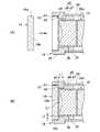
図3、図4及び図5は、それぞれ内視鏡における挿入部先端12の分解斜視図、縦断面図及び横断面図であり、図6は、ホルダカバー56を取り付けたレンズホルダ16の斜視図である。 3, 4, and 5 are an exploded perspective view, a longitudinal sectional view, and a transverse sectional view of the insertion portion
図3に示すように、レンズホルダ16は、略円筒状をなすホルダ本体部25と、ホルダ本体部25の前端部の周縁から径方向に突出するように設けられたフランジ部26と、ホルダ本体部25を支持するようにその下側に設けられた底壁部27とを有しており、それら各部は剛性の高い材料(金属や硬質樹脂等)によって一体に形成されている。 As shown in FIG. 3, the
図4〜図6に示すように、レンズホルダ16は、当該レンズホルダ16を前後方向に貫通するように設けられた筒孔31を有しており、この筒孔31によってレンズホルダ16の内部空間(略円柱状のスペース)が画定される。筒孔31には、カバーガラス19が嵌め込まれた状態で固定されるカバーガラス嵌込部(閉塞部材嵌込部)32と、このカバーガラス嵌込部32よりも小さな外径を有し、レンズユニット15が嵌め込まれる鏡筒嵌込部33とが形成されている。レンズユニット15では、光学材料(ガラス、樹脂等)からなる同一径の複数(ここでは、3枚)の光学レンズL1〜L3と絞り部材35とが、その外殻を形成する円筒状のレンズ枠体である金属製の鏡筒36に互いに光軸LC方向に密接した状態で組み込まれている。 As shown in FIGS. 4 to 6, the
カバーガラス嵌込部32は、図4および図5に示すように、レンズホルダ16の先端部を構成するフランジ部26の内側に位置し、カバーガラス19を嵌め込み可能な形状を有する略凹状の部位として形成されている。カバーガラス19は、カバーガラス嵌込部32に嵌め込まれた状態で接着剤40により固定され、これにより撮像用の光はカバーガラス19を通ってレンズホルダ16内に入射する。本実施形態では、カバーガラス19は、レンズホルダ16内のレンズユニット15を保護する目的で使用されるが、これに限らず、カバーガラス19は、入射光を屈折させて発散または集束させるレンズ機能を有してもよい。 As shown in FIGS. 4 and 5, the cover glass
接着剤40としては、種々の周知の接着剤を用いることができるが、エポキシ樹脂系やアクリル樹脂系などの熱硬化性樹脂が用いられる。或いは、接着剤40としてUV硬化性樹脂を用いてもよい。なお、本明細書における「接着剤」の用語は、固体物の面と面を接着するために用いる物質という厳密な意味のみならず、2つの物の結合に用いることができる物質という程度の広い意味でも用いられる。 As the adhesive 40, various well-known adhesives can be used, but thermosetting resins such as epoxy resin and acrylic resin are used. Alternatively, a UV curable resin may be used as the adhesive 40. Note that the term “adhesive” in the present specification is not limited to the strict meaning of a substance used for bonding a surface of a solid object, but a substance that can be used for bonding two objects. Also used in meaning.
また、カバーガラス嵌込部32は、光軸LCを外囲するように配置された第1の周壁41と、この第1の周壁41の上側(すなわち、カバーガラス19の下部における直線状の変形部20に対応する部位以外)における後端縁の一部から内側に延設され、光軸LCと略垂直に交わる平面上に配置された第1の端壁42とを有している。第1の周壁41および第1の端壁42とは、カバーガラス19の外周面19a(図3参照)および後面19bの一部(外縁部)に当接または近接するように設けられている。 Further, the cover glass
鏡筒嵌込部33は、カバーガラス嵌込部32の後方におけるフランジ部26およびホルダ本体部25の内側に位置し、略円筒状をなす鏡筒36を嵌め込み可能な形状を有している。鏡筒嵌込部33は、光軸LCを外囲するように配置された第2の周壁45と、この第2の周壁45の前端側に設けられた拡径部46とを有する。第2の周壁45は、嵌め込まれた状態のレンズユニット15における鏡筒36の外周面36aに当接または近接するように設けられている。ただし、レンズユニット15は、嵌め込まれた状態においても、後述する固定前の位置調整時においては前後移動が許容される。 The lens
拡径部46は、第2の周壁45における前端縁から外側に延設され、かつ光軸LCと略垂直に交わる平面上に配置された第2の端壁47と、この第2の端壁47における外周縁から前方に延設され、かつ光軸LCを外囲するように配置された第3の周壁48とを有している。詳細は後述するが、第3の周壁48は、拡径部46への接着剤40の浸入前においては、レンズホルダ16(鏡筒36)の少なくとも先端部を非接触の状態で外囲する。このような構成により、拡径部46における鏡筒36の外側のスペースは、レンズホルダ16にカバーガラス19が装着される際に、カバーガラス19の固定に用いられる接着剤40の一部(余剰分)を収容可能な接着剤溜まりとして機能する。 The
ホルダ本体部25の上部には、周方向に延在する略長円形をなす位置固定孔51(図4参照)が設けられている。また、ホルダ本体部25の左右には、レンズホルダ16の位置を調整するための位置調整孔(側面開口部)52(図5参照)がそれぞれ設けられている。左右の位置調整孔52は、それぞれ軸方向に延在する略長円形をなし、互いに対称の位置に配置される。レンズユニット15は、位置調整後に位置固定孔51に注入された接着剤55によってレンズホルダ16に固定される。 A position fixing hole 51 (see FIG. 4) having a substantially oval shape extending in the circumferential direction is provided in the upper part of the holder
また、レンズホルダ16のホルダ本体部25の外周面には、金属製(ステンレス鋼)のホルダカバー56が取り付けられている。ホルダカバー56は、図3に示すように、前後方向から見て円筒の一部が切り欠かれた略C字状をなし、少なくとも位置固定孔51および位置調整孔52を遮蔽するようにホルダ本体部25の外周を覆う。ホルダカバー56は、ホルダ本体部25の外径よりも僅かに大きい内径を有している。ホルダカバー56の前縁は、レンズホルダ16のフランジ部26の後面に接続される。また、ホルダカバー56の左右の下縁は、底壁部27の左右縁にそれぞれ接続される。 Further, a metal (stainless steel)
また、フランジ部26では、図3および図6に示すように、カバーガラス嵌込部32の下方には、左右方向に配置された一対の照明窓61が形成されている。これら照明窓61は、正面視において略円形をなし、ビデオプロセッサ3側に設けられた光源から光ファイバ(ともに図示せず)を介して伝送された光を前方の撮像対象に向けて出射する。また、フランジ部26において、カバーガラス嵌込部32の第1の周壁41は、カバーガラス19の外周面19aの形状に対応するように、上側の円形部41aおよび下側の直線部41b(ともに図6参照)を有している。円形部41aと直線部41bとの境界部には、正面視において周方向外側に突出するように略半円状をなす左右一対の離間部62が形成されている。左右の離間部62は、一対の照明窓61の配置に影響を及ぼさないように、それらを挟み込むように設けられている。 Moreover, in the
後に詳述するように、カバーガラス嵌込部32へのカバーガラス19の装着の際には、カバーガラス嵌込部32の第1の周壁41における円形部41aおよび直線部41b(図6参照)は、カバーガラス19の外周面19aに対して当接または近接する接着面(接着領域)をなし、一方、第1の周壁41における離間部62は、カバーガラス19の外周面19aに対して円形部41aおよび直線部41bよりも離間した面(離間領域)をなす。 As will be described in detail later, when the
イメージセンサ17は、図3に示すように、正面視において(前後方向から見て)略矩形状をなす小型(ここでは、矩形の1辺が1mmの大きさ)のCCD(Charge Coupled Device)またはCMOS(Complementary Metal-Oxide Semiconductor)で構成される。また、イメージセンサ17は、図4に示すように、レンズホルダ16の後壁16aに当接した状態で固定される。レンズホルダ16の後壁16aには、鏡筒嵌込部33に連通する貫通孔64が形成されている。これにより、カバーガラス19を介して入射した光は、鏡筒36内の光学レンズL1〜L3および貫通孔64を通ってイメージセンサ17の受光面に結像する。イメージセンサ17の後部(背面側)には、イメージセンサ17の駆動回路等が設けられた回路基板65が取り付けられている。回路基板65は、前後方向から見てイメージセンサ17よりもやや小さい外形を有している。また、回路基板65の後部(背面側)には、伝送ケーブル11の先端部63が半田付けによって電気的に接続されている。 As shown in FIG. 3, the
リヤカバー18は、図3に示すように、前後方向から見て略D字状をなすように円筒の下部を平坦とした形状を呈しており、上側に位置する筒壁71と、下側に位置する平板状の下壁72とを有している。リヤカバー18の筒壁71には、前端から開口する左右一対の切欠き部73が形成されており、また、下壁72には、前端から開口する切欠き部74が形成されている。左右の切欠き部73は、略矩形状をなし、イメージセンサ17の上側に位置する左右の角部17aに対応する位置にそれぞれ配置されている。図4に示すように、リヤカバー18の後壁18aに形成された略円形のケーブル挿通孔75には、イメージセンサ17と電気的に接続される伝送ケーブル11の先端部63が挿入されている。リヤカバー18の内部には、イメージセンサ17、回路基板65及び伝送ケーブル11の先端部63(イメージセンサ17との電気的な接続部位)を覆うよう封止用の接着剤76が充填されている。 As shown in FIG. 3, the
リヤカバー18は、レンズホルダ16の後部に取り付けられる。リヤカバー18の取付状態においては、ホルダ本体部25の後部がリヤカバー18の筒壁71内に収容されると共に、リヤカバー18の下壁72の前端がレンズホルダ16の下部に設けられた段差部77(図4参照)に当接する。段差部77は、底壁部27を含めたレンズホルダ16の後壁16aの下部が前方に向かって切り欠かれることによって形成されている。なお、底壁部27の下面側には、前後方向に延在する凹状の溝78(図6参照)が形成されている。溝78の前端はフランジ部26の照明窓61と連通しており、溝78内には図示しない光ファイバが挿通される。 The
図7(A)、(B)は、レンズホルダ16に対するカバーガラス19の装着工程を示す説明図である。以下、カバーガラス19の装着工程を含めて、本実施形態に係る内視鏡2の挿入部先端12を組み立てるための一連の工程について説明する。なお、挿入部先端12の組立に際しては調整治具等が使用され、基本的には作業者による顕微鏡を用いた手作業で行われる。 FIGS. 7A and 7B are explanatory views showing a process of attaching the
<イメージセンサ17の装着工程>
イメージセンサ17の装着工程では、作業者は、XYZステージ(図示せず)を操作することで、レンズホルダ16に対するイメージセンサ17(図3参照)の上下および前後位置を調節してイメージセンサ17をレンズホルダ16に当接させる。そこで、イメージセンサ17の中央を光軸LCと略一致させるように、イメージセンサ17の位置が調整される。作業者は、イメージセンサ17を位置決めした後、イメージセンサ17の上辺、右辺、左辺に接着剤を塗布し、イメージセンサ17を固定する。接着剤としてはUV硬化性樹脂を用いることができる。<Mounting process of
In the mounting process of the
<鏡筒36の装着工程>
鏡筒36の装着工程では、作業者は、予め光学レンズL1〜L3等を鏡筒36に組み込むことによりレンズユニット15を組み立てておく。作業者は、レンズユニット15をピンセット等で挟んで、レンズホルダ16内に挿入する。このとき、レンズユニット15は、鏡筒嵌込部33に嵌め込まれる。<Mounting process of
In the mounting process of the
鏡筒36の位置調整には調整治具(図示せず)が用いられる。作業者は、レンズホルダ16に設けられた2つの位置調整孔53(図3参照)から露出する鏡筒36の外周面に、調整治具をそれぞれ押し当て、その押圧力による摩擦力で鏡筒36を保持し、調整治具を鏡筒36の光軸LCの方向(前後方向)に微小量移動させることで、レンズホルダ16における鏡筒36の位置を調整する。この調整により、被写体からの入射光をイメージセンサ17の撮像面に合焦させる(すなわち、ピント合わせを行う)。 An adjustment jig (not shown) is used to adjust the position of the
本実施形態では、調整治具で鏡筒36を左右両側から挟み込むようにしており、1対の調整治具が挿入される2つの位置調整孔53は、それぞれ光軸LCを中心として点対称の位置に設けられている。そして、この位置調整孔53に挿入される調整治具もまた、光軸LCを中心として点対称な位置で鏡筒36の外周面に当接する。このようにすることで、調整治具からの押圧力はいずれも径方向から光軸LCに向けて作用し、鏡筒36には不要な回転力等が加わらず、鏡筒36の変形等を防止することができる。 In this embodiment, the
鏡筒36の位置調整が完了すると、鏡筒36を調整治具で把持したまま(すなわち、レンズホルダ16に対する鏡筒36の相対位置を維持した状態で)、レンズホルダ16の上側面に設けた位置固定孔51に接着剤55(図4参照)が注入される。接着剤55は、位置固定孔51を介して露出しているため、接着剤55としてUV硬化性樹脂を使用することができる。 When the position adjustment of the
接着剤55が硬化した後、調整治具は位置調整孔53から抜去される。調整治具が抜去された後に、位置調整孔53には接着剤55と同様に接着剤を注入してもよい。これによってレンズホルダ16の周方向の広い範囲にわたって鏡筒36が接着され、鏡筒36を確実に固定できるとともに、鏡筒36そのものの機械的強度を向上させることが可能となる。 After the adhesive 55 is cured, the adjustment jig is removed from the
<カバーガラス19の装着工程>
カバーガラス19の装着工程では、作業者は、図7(A)に示すようにカバーガラス嵌込部32の第1の周壁41に微細な刷毛等を使って接着剤40を塗布した後、図7(B)に示すようにカバーガラス19をカバーガラス嵌込部32に嵌め込む。<Installation process of
In the attaching process of the
具体的には、作業者は例えばカバーガラス19の前面を吸盤に吸着して、これを接着剤40が塗布されたカバーガラス嵌込部32に押し込む。このとき、第1の周壁41に塗布された接着剤40の一部(余剰分)は、カバーガラス19の外周部によって内方に押し込まれ、第1の端壁42を伝って拡径部46まで浸入する。これにより、カバーガラス19によるレンズホルダ16の開口の封止性能を低下させることなく、カバーガラス19の後方における光路形成部位(すなわち、カバーガラス19とその後方に配置されたレンズユニット15との間における光の経路)への接着剤40の浸入を防止することが可能となる。 Specifically, for example, the operator adsorbs the front surface of the
なお、接着剤40の余剰分が少ない場合には、拡径部46が接着剤40によって満たされることはない。ただし、少なくとも鏡筒36の外周面36aと拡径部46の内周面(すなわち、第3の周壁48)とが接着剤40によって結合されるように接着剤40の塗布量を調節することにより、鏡筒36(レンズユニット15)の安定的な固定を実現することができるという利点がある。 When the excess amount of the adhesive 40 is small, the
また、カバーガラス19の装着時には、レンズホルダ16には既に鏡筒36が挿入されているため、筒孔31からの空気の流出は多少の制約を受ける。しかしながら、比較的粘性の低い(流動性の高い)接着剤を用いることにより、レンズホルダ16の前方の間隙G1等に残存する空気は、カバーガラス19(外周面19a)と第1の周壁41のとの間において内方に浸入する接着剤40と入れ替わるようにして外方に移動し、カバーガラス嵌込部32の周辺の2カ所に設けた離間部62等から外部に抜け出る。 Further, when the
つまり、レンズホルダ16では、カバーガラス19の装着の際に、離間部62によって空気抜き部が構成されることにより、カバーガラス19の外周面19aとカバーガラス嵌込部32の第1の周壁41(円形部41aおよび直線部41b)との間への接着剤の浸入を容易とすることができる。なお、第1の周壁41の離間部62は、少なくとも空気抜き部を構成するものであればよく、その形状、サイズおよび配置については種々の変更が可能である。 That is, in the
このようにして、作業者はカバーガラス嵌込部32にカバーガラス19を容易に装着することができ、更に、一旦装着されたカバーガラス19が前方に押し出されることもない。なお、カバーガラス嵌込部32の一方にカバーガラス19を片寄して嵌め込んだ際の両者の間隙(クリアランス)は、20〜65μmに設定されている。 In this way, the operator can easily attach the
本実施形態では、鏡筒36の外径は約1mm程度であり、また、カバーガラス19の円形部分(切欠き部分を除く)の外径は約1.4mm程度である。また、拡径部46に形成される接着剤溜まりのサイズについては、光軸方向長さL1が約180〜230μm程度であり、径方向幅L2が約50〜80μm程度である。また、レンズホルダ16の前端とカバーガラス19の後面19bとの間隙G1は、約30〜80μm程度である。このような間隙G1の存在により、レンズユニット15(鏡筒36)の前後方向の位置調整を可能とするスペースを確保することができる。 In the present embodiment, the outer diameter of the
なお、図7(A)では、接着剤40を第1の周壁41に塗布した例を示したが、作業者は、必要に応じて接着剤40を第1の端壁42にも塗布することができる。また、図7(B)では、図示を省略したが、第1の周壁41の表面と同様に第1の端壁42の表面とカバーガラス19の間にも接着剤40の層が形成され得る。 Although FIG. 7A shows an example in which the adhesive 40 is applied to the first
上記カバーガラス19の装着工程において、接着剤40の塗布量が不足している場合には、作業者は、離間部62(図3、図6参照)から図示しない接着剤ディスペンサー(ニードル)などを用いて追加の接着剤を注入することができる。注入された接着剤は、カバーガラス19(外周面19a)と第1の周壁41のとの間における毛細管現象により内方に浸入する。なお、接着剤40の塗布量が過剰でカバーガラス19の外側に接着剤40が排出された場合には、離間部62は接着剤溜まりとしても機能する。 When the application amount of the adhesive 40 is insufficient in the attaching process of the
このようにして、本実施形態では、レンズホルダ16の先端側の開口(撮像窓)は、カバーガラス19によって閉塞され、気密性が確保される。なお、カバーガラス19は光透過性(ここでは、透明)であることから、接着剤40としてUV硬化性樹脂を使用することができ、これによって工程に要する時間を短縮することができる。 Thus, in this embodiment, the opening (imaging window) on the tip side of the
<リヤカバー18の装着工程>
リヤカバー18の装着工程では、前処理として、レンズホルダ16におけるホルダ本体部25の後端よりも後方に位置するイメージセンサ17、回路基板65及び伝送ケーブル11の先端部63を覆うように接着剤76が塗布される。また、リヤカバー18の内部には接着剤76が適度に充填される。接着剤76は、少なくともイメージセンサ17、回路基板65及び伝送ケーブル11の先端を覆い尽くせる程度の高い粘度を備えており、イメージセンサ17より後部において、実質的に水分の浸入を阻止する封止を目的とするものである。接着剤76としては、種々の周知の接着剤を用いることができるが、エポキシ樹脂系やアクリル樹脂系などの熱硬化性樹脂からなる接着剤を用いるとよい。<
In the mounting process of the
上記前処理の後、リヤカバー18はレンズホルダ16の後部に嵌め込まれて、図2および図4に示した状態となる。このとき、リヤカバー18の下壁72の前端は、レンズホルダ16の段差部77の垂直面に当接し、これによりリヤカバー18の前後方向の位置が規制される。また、下壁72の前端部における上面は、段差部77の水平面に当接し、これにより上方向への変位が規制される。また、リヤカバー18の切欠き部73およびケーブル挿通孔75は、通気口として機能するため、リヤカバー18内に接着剤76を安定的に充填することが可能となる。 After the pre-processing, the
<ホルダカバー56の装着工程>
ホルダカバー56の装着工程では、作業者はホルダカバー56の外周面を、図示しない取付治具で支持し、ホルダカバー56の開口側を上方に向けて、その内周面に接着剤を塗布する。塗布される接着剤としては、エポキシ樹脂系やアクリル樹脂系などの熱硬化性樹脂からなる接着剤を用いるとよい。次に、作業者は、ホルダカバー56を、上下反転させ、開口側をレンズホルダ16に設けられた位置固定孔51に対向させる。そして、ホルダカバー56を支持する吸着部を下方に移動させて、レンズホルダ16に対して上方(径方向)から押し付ける。<Mounting process of
In the mounting process of the
C字形状をなすホルダカバー56の開口側は、レンズホルダ16に押し付けられることで左右方向に拡開するように弾性変形する。なお、外力が作用しないときのホルダカバー56の内周面における周方向の曲率は、レンズホルダ16の外周面における周方向の曲率と略同一に設定されている。そして、作業者がホルダカバー56を更に下方に押し込むことにより、拡開状態にあったホルダカバー56は復元し、その内周面の全体によってレンズホルダ16の外周面を把持する。これによりホルダカバー56は自己の弾性変形の復元力によってレンズホルダ16に取り付いた状態となる。 The opening side of the C-shaped
以上、本発明を特定の実施形態に基づいて説明したが、これらの実施形態はあくまでも例示であって、本発明はこれらの実施形態によって限定されるものではない。例えば、本発明に係る内視鏡の挿入部は、軟性鏡としての用途に限定されず、硬性鏡として用いることもできる。また、ホルダ部材に設けられる拡径部の形状やサイズについては、少なくとも閉塞部材を固定するための接着剤の余剰分を収容可能な限りにおいて種々の変更が可能である。なお、上記実施形態に示した本発明に係る内視鏡および内視鏡システムの各構成要素は、必ずしも全てが必須ではなく、少なくとも本発明の範囲を逸脱しない限りにおいて適宜取捨選択することが可能である。 As mentioned above, although this invention was demonstrated based on specific embodiment, these embodiment is an illustration to the last, Comprising: This invention is not limited by these embodiment. For example, the insertion portion of the endoscope according to the present invention is not limited to the use as a flexible endoscope, and can also be used as a rigid endoscope. Moreover, about the shape and size of the enlarged diameter part provided in a holder member, a various change is possible as long as the surplus part of the adhesive agent for fixing a closure member can be accommodated. It should be noted that not all the constituent elements of the endoscope and the endoscope system according to the present invention shown in the above embodiments are necessarily essential, and can be appropriately selected as long as they do not depart from the scope of the present invention. It is.
本発明に係る内視鏡および内視鏡システムは、観察対象の内部に挿入される挿入部の開口に対して接着剤により光透過性の閉塞部材が固定された構成において、当該閉塞部材による開口の封止性能を低下させることなく、当該閉塞部材の後方における光路形成部位への接着剤の浸入を防止することを可能とし、外部から直接観察できない観察対象の内部を撮像する内視鏡および内視鏡システムなどとして有用である。 An endoscope and an endoscope system according to the present invention are configured so that a light-transmissive blocking member is fixed to an opening of an insertion portion inserted into an observation target by an adhesive, and the opening formed by the blocking member An endoscope for imaging the inside of an observation target that cannot be directly observed from the outside, and can prevent the adhesive from entering the optical path forming portion behind the blocking member without degrading the sealing performance of the It is useful as an endoscope system.
1 内視鏡システム
2 内視鏡
5 挿入部
12 挿入部先端
15 レンズユニット(対物レンズ系)
16 レンズホルダ(ホルダ部材)
17 イメージセンサ
18 リヤカバー
19 カバーガラス(閉塞部材)
20 変形部
25 ホルダ本体部
26 フランジ部
27 底壁部
31 筒孔
32 カバーガラス嵌込部(閉塞部材嵌込部)
33 鏡筒嵌込部
36 鏡筒
40 接着剤
41 第1の周壁
41a 円形部(接着領域)
41b 直線部(接着領域)
42 第1の端壁
45 第2の周壁
46 拡径部
47 第2の端壁
48 第3の周壁
52 位置調整孔(側面開口部)
62 離間部(離間領域)
G1 間隙
L1〜L3 光学レンズ
LC 光軸DESCRIPTION OF SYMBOLS 1
16 Lens holder (holder member)
17
20
33 Lens
41b Straight part (bonding area)
42
62 Separating part (separating area)
G1 Gap L1-L3 Optical lens LC Optical axis
Claims (7)
Translated fromJapanese前記挿入部に設けられた略筒状をなすホルダ部材と、
前記ホルダ部材に収容された鏡筒と、
前記鏡筒に保持された対物レンズ系と、
前記ホルダ部材の先端側を閉鎖する光透過性の閉塞部材と
を備え、
前記ホルダ部材の内部空間を画定する筒孔には、前記閉塞部材が嵌め込まれた状態で接着剤により固定される閉塞部材嵌込部と、前記閉塞部材嵌込部よりも小さな径を有し、前記鏡筒が嵌め込まれる鏡筒嵌込部とが形成され、
前記鏡筒嵌込部には、前記閉塞部材嵌込部の後端に連なると共に、前記鏡筒を非接触の状態で外囲する拡径部が設けられたことを特徴とする内視鏡。An endoscope having an insertion portion to be inserted inside an observation object,
A holder member having a substantially cylindrical shape provided in the insertion portion;
A lens barrel housed in the holder member;
An objective lens system held in the barrel;
A light-transmissive blocking member that closes the distal end side of the holder member,
The cylindrical hole that defines the internal space of the holder member has a closing member fitting portion that is fixed by an adhesive in a state in which the closing member is fitted, and a diameter smaller than that of the closing member fitting portion, A lens barrel fitting portion into which the lens barrel is fitted is formed,
The endoscope characterized in that the lens barrel fitting portion is provided with a diameter-expanding portion that is continuous with the rear end of the closing member fitting portion and surrounds the lens barrel in a non-contact state.
Priority Applications (3)
| Application Number | Priority Date | Filing Date | Title |
|---|---|---|---|
| JP2013180395AJP2015047277A (en) | 2013-08-30 | 2013-08-30 | Endoscope and endoscope system |
| US14/471,407US9848757B2 (en) | 2013-08-30 | 2014-08-28 | Endoscope and endoscope system |
| EP14182720.4AEP2842477A1 (en) | 2013-08-30 | 2014-08-28 | Endoscope and endoscope system |
Applications Claiming Priority (1)
| Application Number | Priority Date | Filing Date | Title |
|---|---|---|---|
| JP2013180395AJP2015047277A (en) | 2013-08-30 | 2013-08-30 | Endoscope and endoscope system |
Publications (1)
| Publication Number | Publication Date |
|---|---|
| JP2015047277Atrue JP2015047277A (en) | 2015-03-16 |
Family
ID=51399590
Family Applications (1)
| Application Number | Title | Priority Date | Filing Date |
|---|---|---|---|
| JP2013180395APendingJP2015047277A (en) | 2013-08-30 | 2013-08-30 | Endoscope and endoscope system |
Country Status (3)
| Country | Link |
|---|---|
| US (1) | US9848757B2 (en) |
| EP (1) | EP2842477A1 (en) |
| JP (1) | JP2015047277A (en) |
Cited By (5)
| Publication number | Priority date | Publication date | Assignee | Title |
|---|---|---|---|---|
| JP2017090106A (en)* | 2015-11-05 | 2017-05-25 | ジビル調査設計株式会社 | Structure checkup tool |
| WO2018105894A1 (en)* | 2016-12-06 | 2018-06-14 | 해성옵틱스(주) | Ultra-small endoscope camera module and ultra-small endoscope having same |
| JP2019500108A (en)* | 2015-12-16 | 2019-01-10 | キヤノン ユーエスエイ, インコーポレイテッドCanon U.S.A., Inc | Endoscope system |
| US11690497B2 (en) | 2018-11-27 | 2023-07-04 | Fujikura Ltd. | Lens unit |
| EP3788939B1 (en)* | 2019-09-06 | 2024-01-24 | Ambu A/S | A tip part assembly for an endoscope and a method of manufacture of a tip part assembly of an endoscope |
Families Citing this family (79)
| Publication number | Priority date | Publication date | Assignee | Title |
|---|---|---|---|---|
| US11871901B2 (en) | 2012-05-20 | 2024-01-16 | Cilag Gmbh International | Method for situational awareness for surgical network or surgical network connected device capable of adjusting function based on a sensed situation or usage |
| JP5914784B2 (en)* | 2014-05-16 | 2016-05-11 | オリンパス株式会社 | Endoscopic imaging apparatus and method for assembling endoscopic imaging apparatus |
| JP6412840B2 (en)* | 2015-08-31 | 2018-10-24 | 富士フイルム株式会社 | Endoscope |
| TWI606256B (en)* | 2015-10-08 | 2017-11-21 | 先進光電科技股份有限公司 | Optical image capturing system |
| EP3369359A4 (en)* | 2015-10-27 | 2019-06-05 | Olympus Corporation | Imaging device and endoscope |
| CN109068948B (en)* | 2016-06-27 | 2021-08-24 | 奥林巴斯株式会社 | Endoscope, endoscope manufacturing method |
| CN106943115A (en)* | 2016-10-08 | 2017-07-14 | 上海安清医疗器械有限公司 | Endoscope leading end portion, endoscope focus adjustment method and endoscope |
| JP6617206B2 (en)* | 2016-10-25 | 2019-12-11 | 富士フイルム株式会社 | Endoscope |
| JP6713544B2 (en)* | 2016-10-25 | 2020-06-24 | 富士フイルム株式会社 | Endoscope |
| JP6953223B2 (en) | 2017-08-02 | 2021-10-27 | パナソニックi−PROセンシングソリューションズ株式会社 | Endoscope |
| US11564756B2 (en) | 2017-10-30 | 2023-01-31 | Cilag Gmbh International | Method of hub communication with surgical instrument systems |
| US11510741B2 (en) | 2017-10-30 | 2022-11-29 | Cilag Gmbh International | Method for producing a surgical instrument comprising a smart electrical system |
| US11801098B2 (en) | 2017-10-30 | 2023-10-31 | Cilag Gmbh International | Method of hub communication with surgical instrument systems |
| US11291510B2 (en) | 2017-10-30 | 2022-04-05 | Cilag Gmbh International | Method of hub communication with surgical instrument systems |
| US11911045B2 (en) | 2017-10-30 | 2024-02-27 | Cllag GmbH International | Method for operating a powered articulating multi-clip applier |
| US11925373B2 (en) | 2017-10-30 | 2024-03-12 | Cilag Gmbh International | Surgical suturing instrument comprising a non-circular needle |
| US12396806B2 (en) | 2017-12-28 | 2025-08-26 | Cilag Gmbh International | Adjustment of a surgical device function based on situational awareness |
| US11937769B2 (en) | 2017-12-28 | 2024-03-26 | Cilag Gmbh International | Method of hub communication, processing, storage and display |
| US11179175B2 (en) | 2017-12-28 | 2021-11-23 | Cilag Gmbh International | Controlling an ultrasonic surgical instrument according to tissue location |
| US12127729B2 (en) | 2017-12-28 | 2024-10-29 | Cilag Gmbh International | Method for smoke evacuation for surgical hub |
| US20190201142A1 (en) | 2017-12-28 | 2019-07-04 | Ethicon Llc | Automatic tool adjustments for robot-assisted surgical platforms |
| US11376002B2 (en) | 2017-12-28 | 2022-07-05 | Cilag Gmbh International | Surgical instrument cartridge sensor assemblies |
| US11304699B2 (en) | 2017-12-28 | 2022-04-19 | Cilag Gmbh International | Method for adaptive control schemes for surgical network control and interaction |
| US11013563B2 (en) | 2017-12-28 | 2021-05-25 | Ethicon Llc | Drive arrangements for robot-assisted surgical platforms |
| US11026751B2 (en) | 2017-12-28 | 2021-06-08 | Cilag Gmbh International | Display of alignment of staple cartridge to prior linear staple line |
| US11559308B2 (en) | 2017-12-28 | 2023-01-24 | Cilag Gmbh International | Method for smart energy device infrastructure |
| US11202570B2 (en) | 2017-12-28 | 2021-12-21 | Cilag Gmbh International | Communication hub and storage device for storing parameters and status of a surgical device to be shared with cloud based analytics systems |
| US11389164B2 (en) | 2017-12-28 | 2022-07-19 | Cilag Gmbh International | Method of using reinforced flexible circuits with multiple sensors to optimize performance of radio frequency devices |
| US11076921B2 (en) | 2017-12-28 | 2021-08-03 | Cilag Gmbh International | Adaptive control program updates for surgical hubs |
| US11744604B2 (en) | 2017-12-28 | 2023-09-05 | Cilag Gmbh International | Surgical instrument with a hardware-only control circuit |
| US11324557B2 (en) | 2017-12-28 | 2022-05-10 | Cilag Gmbh International | Surgical instrument with a sensing array |
| WO2019133144A1 (en) | 2017-12-28 | 2019-07-04 | Ethicon Llc | Detection and escalation of security responses of surgical instruments to increasing severity threats |
| US11969216B2 (en) | 2017-12-28 | 2024-04-30 | Cilag Gmbh International | Surgical network recommendations from real time analysis of procedure variables against a baseline highlighting differences from the optimal solution |
| US11786251B2 (en) | 2017-12-28 | 2023-10-17 | Cilag Gmbh International | Method for adaptive control schemes for surgical network control and interaction |
| US11464559B2 (en) | 2017-12-28 | 2022-10-11 | Cilag Gmbh International | Estimating state of ultrasonic end effector and control system therefor |
| US20190206569A1 (en) | 2017-12-28 | 2019-07-04 | Ethicon Llc | Method of cloud based data analytics for use with the hub |
| US11903601B2 (en) | 2017-12-28 | 2024-02-20 | Cilag Gmbh International | Surgical instrument comprising a plurality of drive systems |
| US11166772B2 (en) | 2017-12-28 | 2021-11-09 | Cilag Gmbh International | Surgical hub coordination of control and communication of operating room devices |
| US11832899B2 (en) | 2017-12-28 | 2023-12-05 | Cilag Gmbh International | Surgical systems with autonomously adjustable control programs |
| US20190201112A1 (en) | 2017-12-28 | 2019-07-04 | Ethicon Llc | Computer implemented interactive surgical systems |
| US20190201039A1 (en) | 2017-12-28 | 2019-07-04 | Ethicon Llc | Situational awareness of electrosurgical systems |
| US11666331B2 (en) | 2017-12-28 | 2023-06-06 | Cilag Gmbh International | Systems for detecting proximity of surgical end effector to cancerous tissue |
| US12376855B2 (en) | 2017-12-28 | 2025-08-05 | Cilag Gmbh International | Safety systems for smart powered surgical stapling |
| US11857152B2 (en) | 2017-12-28 | 2024-01-02 | Cilag Gmbh International | Surgical hub spatial awareness to determine devices in operating theater |
| US11896322B2 (en) | 2017-12-28 | 2024-02-13 | Cilag Gmbh International | Sensing the patient position and contact utilizing the mono-polar return pad electrode to provide situational awareness to the hub |
| US10918310B2 (en) | 2018-01-03 | 2021-02-16 | Biosense Webster (Israel) Ltd. | Fast anatomical mapping (FAM) using volume filling |
| US11132462B2 (en) | 2017-12-28 | 2021-09-28 | Cilag Gmbh International | Data stripping method to interrogate patient records and create anonymized record |
| US12062442B2 (en) | 2017-12-28 | 2024-08-13 | Cilag Gmbh International | Method for operating surgical instrument systems |
| US11864728B2 (en) | 2017-12-28 | 2024-01-09 | Cilag Gmbh International | Characterization of tissue irregularities through the use of mono-chromatic light refractivity |
| US12096916B2 (en) | 2017-12-28 | 2024-09-24 | Cilag Gmbh International | Method of sensing particulate from smoke evacuated from a patient, adjusting the pump speed based on the sensed information, and communicating the functional parameters of the system to the hub |
| US11696760B2 (en) | 2017-12-28 | 2023-07-11 | Cilag Gmbh International | Safety systems for smart powered surgical stapling |
| US20190201090A1 (en) | 2017-12-28 | 2019-07-04 | Ethicon Llc | Capacitive coupled return path pad with separable array elements |
| US11998193B2 (en) | 2017-12-28 | 2024-06-04 | Cilag Gmbh International | Method for usage of the shroud as an aspect of sensing or controlling a powered surgical device, and a control algorithm to adjust its default operation |
| US11633237B2 (en) | 2017-12-28 | 2023-04-25 | Cilag Gmbh International | Usage and technique analysis of surgeon / staff performance against a baseline to optimize device utilization and performance for both current and future procedures |
| US11818052B2 (en) | 2017-12-28 | 2023-11-14 | Cilag Gmbh International | Surgical network determination of prioritization of communication, interaction, or processing based on system or device needs |
| US10758310B2 (en) | 2017-12-28 | 2020-09-01 | Ethicon Llc | Wireless pairing of a surgical device with another device within a sterile surgical field based on the usage and situational awareness of devices |
| US11896443B2 (en) | 2017-12-28 | 2024-02-13 | Cilag Gmbh International | Control of a surgical system through a surgical barrier |
| US11311306B2 (en) | 2017-12-28 | 2022-04-26 | Cilag Gmbh International | Surgical systems for detecting end effector tissue distribution irregularities |
| US11678881B2 (en) | 2017-12-28 | 2023-06-20 | Cilag Gmbh International | Spatial awareness of surgical hubs in operating rooms |
| US11969142B2 (en) | 2017-12-28 | 2024-04-30 | Cilag Gmbh International | Method of compressing tissue within a stapling device and simultaneously displaying the location of the tissue within the jaws |
| US11612444B2 (en) | 2017-12-28 | 2023-03-28 | Cilag Gmbh International | Adjustment of a surgical device function based on situational awareness |
| US11109866B2 (en) | 2017-12-28 | 2021-09-07 | Cilag Gmbh International | Method for circular stapler control algorithm adjustment based on situational awareness |
| US11257589B2 (en) | 2017-12-28 | 2022-02-22 | Cilag Gmbh International | Real-time analysis of comprehensive cost of all instrumentation used in surgery utilizing data fluidity to track instruments through stocking and in-house processes |
| JP7013249B2 (en)* | 2018-01-16 | 2022-01-31 | オリンパス株式会社 | Ultrasonic probe |
| US11986233B2 (en) | 2018-03-08 | 2024-05-21 | Cilag Gmbh International | Adjustment of complex impedance to compensate for lost power in an articulating ultrasonic device |
| US11534196B2 (en) | 2018-03-08 | 2022-12-27 | Cilag Gmbh International | Using spectroscopy to determine device use state in combo instrument |
| US11259830B2 (en) | 2018-03-08 | 2022-03-01 | Cilag Gmbh International | Methods for controlling temperature in ultrasonic device |
| TWI670539B (en)* | 2018-03-14 | 2019-09-01 | 先進光電科技股份有限公司 | Optical image capturing system |
| US11589865B2 (en) | 2018-03-28 | 2023-02-28 | Cilag Gmbh International | Methods for controlling a powered surgical stapler that has separate rotary closure and firing systems |
| US11090047B2 (en) | 2018-03-28 | 2021-08-17 | Cilag Gmbh International | Surgical instrument comprising an adaptive control system |
| DE112019002160T5 (en) | 2018-04-25 | 2021-03-04 | Panasonic I-Pro Sensing Solutions Co., Ltd. | endoscope |
| US11331100B2 (en) | 2019-02-19 | 2022-05-17 | Cilag Gmbh International | Staple cartridge retainer system with authentication keys |
| CN113382669A (en)* | 2019-03-18 | 2021-09-10 | 奥林巴斯株式会社 | Endoscope front end unit |
| US11794389B2 (en) | 2019-09-06 | 2023-10-24 | Ambu A/S | Tip part assembly for an endoscope |
| CN111227776A (en)* | 2020-03-25 | 2020-06-05 | 徐州市广科新技术发展有限公司 | Endoscopic vagina examination equipment and using method thereof |
| CN111227777A (en)* | 2020-03-25 | 2020-06-05 | 徐州市广科新技术发展有限公司 | Entering type vagina camera system and using method thereof |
| JP7498581B2 (en)* | 2020-03-26 | 2024-06-12 | 株式会社フジクラ | Endoscope |
| EP4018908A1 (en)* | 2020-12-22 | 2022-06-29 | Ambu A/S | An endoscope |
| CN118970810B (en)* | 2024-10-17 | 2025-02-18 | 湖南省华芯医疗器械有限公司 | Endoscope cable protective cover and endoscope |
Family Cites Families (8)
| Publication number | Priority date | Publication date | Assignee | Title |
|---|---|---|---|---|
| JP3737848B2 (en) | 1995-12-25 | 2006-01-25 | ペンタックス株式会社 | Endoscope exposed part fixing part |
| EP1008882A4 (en)* | 1997-08-01 | 2009-10-21 | Olympus Optical Co | Objective of endoscope |
| JP2002336190A (en)* | 2001-03-12 | 2002-11-26 | Olympus Optical Co Ltd | Endoscope |
| JP4061156B2 (en)* | 2002-09-02 | 2008-03-12 | オリンパス株式会社 | Optical unit assembling method and optical unit assembling apparatus |
| JP5124376B2 (en)* | 2008-07-22 | 2013-01-23 | 富士フイルム株式会社 | Endoscope optical system apparatus and endoscope provided with the same |
| JP2011130918A (en)* | 2009-12-24 | 2011-07-07 | Olympus Corp | Endoscope apparatus and optical adapter used in the same |
| JP5261518B2 (en)* | 2011-03-01 | 2013-08-14 | 富士フイルム株式会社 | Endoscope |
| US9405114B2 (en)* | 2011-04-08 | 2016-08-02 | Fujifilm Corporation | Camera module for endoscope |
- 2013
- 2013-08-30JPJP2013180395Apatent/JP2015047277A/enactivePending
- 2014
- 2014-08-28USUS14/471,407patent/US9848757B2/ennot_activeExpired - Fee Related
- 2014-08-28EPEP14182720.4Apatent/EP2842477A1/ennot_activeWithdrawn
Cited By (6)
| Publication number | Priority date | Publication date | Assignee | Title |
|---|---|---|---|---|
| JP2017090106A (en)* | 2015-11-05 | 2017-05-25 | ジビル調査設計株式会社 | Structure checkup tool |
| JP2019500108A (en)* | 2015-12-16 | 2019-01-10 | キヤノン ユーエスエイ, インコーポレイテッドCanon U.S.A., Inc | Endoscope system |
| WO2018105894A1 (en)* | 2016-12-06 | 2018-06-14 | 해성옵틱스(주) | Ultra-small endoscope camera module and ultra-small endoscope having same |
| US11278193B2 (en) | 2016-12-06 | 2022-03-22 | Haesung Optics | Micro endoscope camera module and micro endoscope having same |
| US11690497B2 (en) | 2018-11-27 | 2023-07-04 | Fujikura Ltd. | Lens unit |
| EP3788939B1 (en)* | 2019-09-06 | 2024-01-24 | Ambu A/S | A tip part assembly for an endoscope and a method of manufacture of a tip part assembly of an endoscope |
Also Published As
| Publication number | Publication date |
|---|---|
| US20150062316A1 (en) | 2015-03-05 |
| EP2842477A1 (en) | 2015-03-04 |
| US9848757B2 (en) | 2017-12-26 |
Similar Documents
| Publication | Publication Date | Title |
|---|---|---|
| JP2015047277A (en) | Endoscope and endoscope system | |
| JP5124376B2 (en) | Endoscope optical system apparatus and endoscope provided with the same | |
| JP5721981B2 (en) | Imaging unit and endoscope including imaging unit | |
| EP2680059B1 (en) | A pickup imaging assembly, endoscope, and method of manufacturing a pickup imaging assembly | |
| JP5167437B2 (en) | Imaging device | |
| JP2014230638A (en) | Endoscope and endoscope system | |
| WO2011092901A1 (en) | Image pickup unit for endoscope | |
| JP2015073540A (en) | Endoscope and method for producing endoscope | |
| US11122969B2 (en) | Endoscopic device | |
| JP2015058118A (en) | Endoscope | |
| JP6461816B2 (en) | Imaging apparatus and endoscope apparatus | |
| JP2012170765A (en) | Endoscope | |
| EP2719321A1 (en) | Endoscope image pickup unit and endoscope | |
| JP5389376B2 (en) | Endoscope imaging unit | |
| JP5374669B1 (en) | Endoscope | |
| EP2570072B1 (en) | Method for assembling endoscopic imaging unit and endoscope | |
| CN113382671B (en) | Front end unit of endoscope and endoscope | |
| JP2015073537A (en) | Endoscope and endoscope system | |
| JP2015047278A (en) | Endoscope | |
| JP2014119474A (en) | Imaging unit, endoscope device, and manufacturing method of imaging unit | |
| JP6576098B2 (en) | Medical camera device | |
| JP6727964B2 (en) | Endoscope | |
| JP2012029114A (en) | Imaging apparatus | |
| JP2015039547A (en) | Endoscope | |
| JP2015047249A (en) | Endoscope |