JP2015042266A - Modular type portable dialysis system - Google Patents
Modular type portable dialysis systemDownload PDFInfo
- Publication number
- JP2015042266A JP2015042266AJP2014203093AJP2014203093AJP2015042266AJP 2015042266 AJP2015042266 AJP 2015042266AJP 2014203093 AJP2014203093 AJP 2014203093AJP 2014203093 AJP2014203093 AJP 2014203093AJP 2015042266 AJP2015042266 AJP 2015042266A
- Authority
- JP
- Japan
- Prior art keywords
- outer housing
- unit
- dialysis system
- door
- hook
- Prior art date
- Legal status (The legal status is an assumption and is not a legal conclusion. Google has not performed a legal analysis and makes no representation as to the accuracy of the status listed.)
- Granted
Links
Images


Classifications
- A—HUMAN NECESSITIES
- A61—MEDICAL OR VETERINARY SCIENCE; HYGIENE
- A61M—DEVICES FOR INTRODUCING MEDIA INTO, OR ONTO, THE BODY; DEVICES FOR TRANSDUCING BODY MEDIA OR FOR TAKING MEDIA FROM THE BODY; DEVICES FOR PRODUCING OR ENDING SLEEP OR STUPOR
- A61M1/00—Suction or pumping devices for medical purposes; Devices for carrying-off, for treatment of, or for carrying-over, body-liquids; Drainage systems
- A61M1/14—Dialysis systems; Artificial kidneys; Blood oxygenators ; Reciprocating systems for treatment of body fluids, e.g. single needle systems for hemofiltration or pheresis
- B—PERFORMING OPERATIONS; TRANSPORTING
- B01—PHYSICAL OR CHEMICAL PROCESSES OR APPARATUS IN GENERAL
- B01D—SEPARATION
- B01D61/00—Processes of separation using semi-permeable membranes, e.g. dialysis, osmosis or ultrafiltration; Apparatus, accessories or auxiliary operations specially adapted therefor
- B01D61/24—Dialysis ; Membrane extraction
- B01D61/28—Apparatus therefor
- B—PERFORMING OPERATIONS; TRANSPORTING
- B01—PHYSICAL OR CHEMICAL PROCESSES OR APPARATUS IN GENERAL
- B01D—SEPARATION
- B01D61/00—Processes of separation using semi-permeable membranes, e.g. dialysis, osmosis or ultrafiltration; Apparatus, accessories or auxiliary operations specially adapted therefor
- B01D61/24—Dialysis ; Membrane extraction
- B01D61/30—Accessories; Auxiliary operation
- G—PHYSICS
- G16—INFORMATION AND COMMUNICATION TECHNOLOGY [ICT] SPECIALLY ADAPTED FOR SPECIFIC APPLICATION FIELDS
- G16H—HEALTHCARE INFORMATICS, i.e. INFORMATION AND COMMUNICATION TECHNOLOGY [ICT] SPECIALLY ADAPTED FOR THE HANDLING OR PROCESSING OF MEDICAL OR HEALTHCARE DATA
- G16H20/00—ICT specially adapted for therapies or health-improving plans, e.g. for handling prescriptions, for steering therapy or for monitoring patient compliance
- G16H20/40—ICT specially adapted for therapies or health-improving plans, e.g. for handling prescriptions, for steering therapy or for monitoring patient compliance relating to mechanical, radiation or invasive therapies, e.g. surgery, laser therapy, dialysis or acupuncture
- G—PHYSICS
- G16—INFORMATION AND COMMUNICATION TECHNOLOGY [ICT] SPECIALLY ADAPTED FOR SPECIFIC APPLICATION FIELDS
- G16H—HEALTHCARE INFORMATICS, i.e. INFORMATION AND COMMUNICATION TECHNOLOGY [ICT] SPECIALLY ADAPTED FOR THE HANDLING OR PROCESSING OF MEDICAL OR HEALTHCARE DATA
- G16H40/00—ICT specially adapted for the management or administration of healthcare resources or facilities; ICT specially adapted for the management or operation of medical equipment or devices
- G16H40/60—ICT specially adapted for the management or administration of healthcare resources or facilities; ICT specially adapted for the management or operation of medical equipment or devices for the operation of medical equipment or devices
- G16H40/63—ICT specially adapted for the management or administration of healthcare resources or facilities; ICT specially adapted for the management or operation of medical equipment or devices for the operation of medical equipment or devices for local operation
- A—HUMAN NECESSITIES
- A61—MEDICAL OR VETERINARY SCIENCE; HYGIENE
- A61M—DEVICES FOR INTRODUCING MEDIA INTO, OR ONTO, THE BODY; DEVICES FOR TRANSDUCING BODY MEDIA OR FOR TAKING MEDIA FROM THE BODY; DEVICES FOR PRODUCING OR ENDING SLEEP OR STUPOR
- A61M2205/00—General characteristics of the apparatus
- A61M2205/12—General characteristics of the apparatus with interchangeable cassettes forming partially or totally the fluid circuit
- A61M2205/121—General characteristics of the apparatus with interchangeable cassettes forming partially or totally the fluid circuit interface between cassette and base
- A—HUMAN NECESSITIES
- A61—MEDICAL OR VETERINARY SCIENCE; HYGIENE
- A61M—DEVICES FOR INTRODUCING MEDIA INTO, OR ONTO, THE BODY; DEVICES FOR TRANSDUCING BODY MEDIA OR FOR TAKING MEDIA FROM THE BODY; DEVICES FOR PRODUCING OR ENDING SLEEP OR STUPOR
- A61M2205/00—General characteristics of the apparatus
- A61M2205/35—Communication
- A61M2205/3546—Range
- A61M2205/3569—Range sublocal, e.g. between console and disposable
- A—HUMAN NECESSITIES
- A61—MEDICAL OR VETERINARY SCIENCE; HYGIENE
- A61M—DEVICES FOR INTRODUCING MEDIA INTO, OR ONTO, THE BODY; DEVICES FOR TRANSDUCING BODY MEDIA OR FOR TAKING MEDIA FROM THE BODY; DEVICES FOR PRODUCING OR ENDING SLEEP OR STUPOR
- A61M2209/00—Ancillary equipment
- A61M2209/08—Supports for equipment
- A61M2209/084—Supporting bases, stands for equipment
- B—PERFORMING OPERATIONS; TRANSPORTING
- B01—PHYSICAL OR CHEMICAL PROCESSES OR APPARATUS IN GENERAL
- B01D—SEPARATION
- B01D2313/00—Details relating to membrane modules or apparatus
- B01D2313/20—Specific housing
- B01D2313/205—Specific housing characterised by the shape
- B—PERFORMING OPERATIONS; TRANSPORTING
- B01—PHYSICAL OR CHEMICAL PROCESSES OR APPARATUS IN GENERAL
- B01D—SEPARATION
- B01D2313/00—Details relating to membrane modules or apparatus
- B01D2313/20—Specific housing
- B01D2313/208—Resilient or flexible housing walls, e.g. bags or foils
Landscapes
- Health & Medical Sciences (AREA)
- Engineering & Computer Science (AREA)
- Urology & Nephrology (AREA)
- Heart & Thoracic Surgery (AREA)
- Biomedical Technology (AREA)
- Public Health (AREA)
- General Health & Medical Sciences (AREA)
- Water Supply & Treatment (AREA)
- Chemical & Material Sciences (AREA)
- Chemical Kinetics & Catalysis (AREA)
- Life Sciences & Earth Sciences (AREA)
- Hematology (AREA)
- Anesthesiology (AREA)
- Animal Behavior & Ethology (AREA)
- Vascular Medicine (AREA)
- Emergency Medicine (AREA)
- Veterinary Medicine (AREA)
- Medical Informatics (AREA)
- Epidemiology (AREA)
- Primary Health Care (AREA)
- General Business, Economics & Management (AREA)
- Business, Economics & Management (AREA)
- Nuclear Medicine, Radiotherapy & Molecular Imaging (AREA)
- Surgery (AREA)
- External Artificial Organs (AREA)
Abstract
Description
Translated fromJapanese〔関連出願へのクロスリファレンス〕本願は、2008年10月30日に出願された米国仮特許出願第61/109、834号を基礎とする優先権主張出願である。本願は、また、2009年10月7日に出願された米国特許出願第12/575、450号、2009年10月7日に出願された米国特許出願第12/575、449号、2009年1月16日に出願された米国特許出願第12/355、102号、2009年1月16日に出願された米国特許出願第12/355、128号、2009年1月12日に出願された米国特許出願第12/351、969号、2008年11月28日に出願された米国特許出願第12/324、924号、2008年9月12日に出願された米国特許出願第12/210、080号、2008年9月25日に出願された米国特許出願第12/238、055号、2008年9月25日に出願された米国特許出願第12/237、914号、2008年10月10日に出願された米国特許出願第12/249、090号、2008年10月3日に出願された米国特許出願第12/245、397号に関連する。これら全ての出願の内容は、参照することにより盛り込まれる。 [Cross Reference to Related Applications] This application is a priority application based on US Provisional Patent Application No. 61 / 109,834 filed on Oct. 30, 2008. This application also includes US patent application Ser. No. 12 / 575,450, filed Oct. 7, 2009, and U.S. patent application Ser. No. 12 / 575,449, filed Oct. 7, 2009. U.S. Patent Application No. 12 / 355,102 filed on Jan. 16, US Patent Application No. 12 / 355,128 filed Jan. 16, 2009, U.S. Application filed on Jan. 12, 2009 Patent Application No. 12 / 351,969, US Patent Application No. 12 / 324,924 filed on November 28, 2008, US Patent Application No. 12 / 210,080 filed on September 12, 2008 No. 12 / 238,055 filed on Sep. 25, 2008, U.S. Patent Application No. 12 / 237,914 filed on Sep. 25, 2008, Oct. 10, 2008 U.S. Patent Application No. 12 / 249,090, filed, related to U.S. Patent Application No. 12 / 245,397, filed Oct. 3, 2008. The contents of all these applications are incorporated by reference.
本発明は、改良された構造的及び機能的特徴を有する透析システムに関する。特に、本発明による透析システムは、改良されたモジュール性、使い安さ、及び安全性を有する携帯透析システムに関する。 The present invention relates to a dialysis system having improved structural and functional characteristics. In particular, the dialysis system according to the present invention relates to a portable dialysis system having improved modularity, ease of use, and safety.
腎不全患者の身体から有害な老廃物を取り除くために、血液透析が行われる。患者の血液はチューブを介して一時的に体外に取り出され、透析装置内で少なくとも1の半透膜に通される。半透膜は、例えば中空糸の集まりで構成されていて、透析液と血液との間を仕切るものである。血液中の不純物は、主に浸透圧により、膜を通過して透析液中へ移動する。浄化された血液は、その後、体内へ戻される。Hemodialysis is performed to remove harmful waste products from the body of patients with renal failure. The patient's blood is temporarily removed from the body through a tube and passed through at least one semipermeable membrane in the dialyzer. The semipermeable membrane is constituted by a collection of hollow fibers, for example, and partitions between the dialysate and the blood. Impurities in the blood move through the membrane and into the dialysate, mainly due to osmotic pressure. The purified blood is then returned to the body.
病院に設置された装置を用いた通常の透析療法は、次の2つの段階を有する。(a)透析。ここでは、有害物質やスコリア(通常は小さな分子)が血液中から半透膜を通って透析液へ移動する。(b)限外ろ過。ここでは、血液回路と透析液回路間の圧力差、より具体的には、後者の回路における減圧により、血液中の水分が所定量減少する。 Conventional dialysis therapy using a device installed in a hospital has the following two stages. (A) Dialysis. Here, harmful substances and scoria (usually small molecules) move from the blood through the semipermeable membrane to the dialysate. (B) Ultrafiltration. Here, due to the pressure difference between the blood circuit and the dialysate circuit, more specifically, the pressure in the latter circuit reduces the moisture in the blood by a predetermined amount.
通常の装置を用いた透析治療は煩わしく、コストも高くなりやすい。加えて、患者は長時間にわたって透析センターに拘束される。携帯透析システムが開発されている。米国特許第4、083、777は、老廃不純物を血液中から透析液中へ移すために、老廃不純物を含む血液及び透析液が間接的物質移動透析関係によって通過する透析手段を備える血液透過システムを開示している。この装置は、老廃不純物を含む血液を患者から該透析手段へ送り出すための手段と、血流回路を構成して老廃不純物が取り除かれた血液を患者へ戻すための手段とを備える。該透析手段は、血液を送り出すための撓性弾性管体ポンプ駆動セクションを有する。蠕動ポンプ手段には、回転可能なポンプヘッドアセンブリが設けられている。このアセンブリは、固定軸を中心に回転可能に設けられたベース部材を有し、ここには円周方向に離間された複数のローラが装着されている。これらローラは、ベース部材の固定軸と平行なそれぞれの軸を中心に独立して回転可能にされている。 Dialysis treatment using a normal device is cumbersome and costly. In addition, the patient is restrained in the dialysis center for a long time. A portable dialysis system has been developed. U.S. Pat. No. 4,083,777 discloses a blood permeation system comprising dialysis means through which blood and dialysate containing waste impurities pass through an indirect mass transfer dialysis relationship in order to transfer the waste impurities from the blood into the dialysate. Disclosure. The apparatus comprises means for pumping blood containing waste impurities from the patient to the dialysis means and means for constructing a blood flow circuit to return the blood from which the waste impurities have been removed to the patient. The dialysis means has a flexible elastic tubular pump drive section for pumping blood. The peristaltic pump means is provided with a rotatable pump head assembly. The assembly includes a base member that is rotatably provided around a fixed shaft, and a plurality of rollers that are spaced apart in the circumferential direction are attached thereto. These rollers are independently rotatable about respective axes parallel to the fixed axis of the base member.
米国特許第4、443、333号は、血液透析を行うための携帯システムが開示されている。ここでは、血液は交換ステーションを通過するが、このとき血液は半透膜の片側と接触し、透析液は当該半透膜の反対側と接触する。このシステムは、血液を複数のステーションを通過させるために血液源に接続されると共に血液を血液源へ戻すための伸縮性チューブ手段と、当該血液チューブ手段と連通する血栓検出器及び気泡検出器と、透析液を複数のステーションを通過させるために透析液源に接続される伸縮性チューブ手段と、透析液の液流、圧力、温度、及び伝導性を測定して制御するための手段と、交換ステーションを通過する際の透析液の圧力を血液の圧力よりも小さい値に維持するための手段と、少なくとも、血液を伸縮性血液手段へ送るための蠕動ポンプと透析液を伸縮性透析液チューブ手段へ送るための蠕動ポンプの2つのポンプに接続された出力軸を有する1のモータ手段と、当該モータ手段と当該蠕動ポンプと関連して透析液流を血液流の約3倍に維持する機構とを備える。各蠕動ポンプは内側アーチ面を有する。血液ポンプは、間に血液チューブ手段を捕捉するために当該内側アーチ座面と関連する少なくとも1のローラを有する。透析液ポンプは、間に透析液チューブ手段を捕捉するために該内側アーチ座面と関連する1のローラを有する。蠕動血液ポンプを作動させると、ローラによって血液チューブ手段の中で滑らかな血液の層流が発生する。蠕動透析液ポンプを作動させると、当該1のローラによって発生する真空によって透析液流が発生し、これにより伸縮性透析液チューブ手段の変形と復帰が生じる。このシステムは更に制御機構を有する。当該制御機構は、血液漏出検出器及び気泡検出器と、モータ手段と、透析の液流・圧力・温度・伝導性測定手段に対して動作可能に接続されていて、圧力、温度、又は伝導性の測定値が所定範囲から外れた場合に、血液流を維持したまま透析液ローラを選択的に停止させることにより透析液チューブ手段及び交換ステーション内での透析液の移動を停止させ、また、血液漏出検出器又は気泡検出器からの信号に基づき全てのローラを同時に停止させることにより、全システム及びポンプ動作を停止させる。 U.S. Pat. No. 4,443,333 discloses a portable system for performing hemodialysis. Here, the blood passes through the exchange station, at which time the blood contacts one side of the semipermeable membrane and the dialysate contacts the opposite side of the semipermeable membrane. The system includes a telescoping tube means connected to a blood source for passing blood through a plurality of stations and returning blood to the blood source, a thrombus detector and a bubble detector communicating with the blood tube means, Replacing elastic tube means connected to the dialysate source for passing dialysate through multiple stations and means for measuring and controlling dialysate fluid flow, pressure, temperature, and conductivity Means for maintaining the pressure of the dialysate when passing through the station at a value smaller than the pressure of blood, and at least a peristaltic pump for sending blood to the stretchable blood means and a dialysate for the stretchable dialysate tube means A motor means having an output shaft connected to the two pumps of the peristaltic pump for delivery to the motor, and in connection with the motor means and the peristaltic pump, the dialysate flow is approximately three times the blood flow And a mechanism for lifting. Each peristaltic pump has an inner arch surface. The blood pump has at least one roller associated with the inner arched surface to capture the blood tube means therebetween. The dialysate pump has one roller associated with the inner arch seat surface to capture the dialysate tube means therebetween. When the peristaltic blood pump is activated, a smooth laminar flow of blood is generated in the blood tube means by the rollers. When the peristaltic dialysate pump is operated, a dialysate flow is generated by the vacuum generated by the one roller, thereby causing deformation and return of the elastic dialysate tube means. The system further has a control mechanism. The control mechanism is operatively connected to the blood leak detector and bubble detector, the motor means, and the dialysis fluid flow / pressure / temperature / conductivity measuring means, and the pressure, temperature, or conductivity When the measured value deviates from the predetermined range, the movement of the dialysate in the dialysate tube means and the exchange station is stopped by selectively stopping the dialysate roller while maintaining the blood flow. The entire system and pump operation are stopped by simultaneously stopping all rollers based on the signal from the leak detector or bubble detector.
米国特許第6、168、578号は、廃液袋を搭載したベルトを備える携帯腎臓透析システムを開示している。ベルトにはポンプも搭載されていて、当該ポンプはユーザと廃液袋の間に接続される。ポンプは、排出信号を受信すると、ユーザから廃液袋へ液体を送り出す。また、廃液袋が一杯になると検出する圧力スイッチも設けられている。制御機構は、廃液袋が一杯であると検出されていない場合に限り、排出信号をポンプへ送る役割を果たす。従来の他の携帯血液透析システムとしては、ネクステージ社製のシステムワンと呼ばれる携帯透析システムが挙げられる。 US Pat. No. 6,168,578 discloses a portable kidney dialysis system that includes a belt carrying a waste bag. A pump is also mounted on the belt, and the pump is connected between the user and the waste liquid bag. When the pump receives the discharge signal, the pump sends the liquid from the user to the waste bag. A pressure switch is also provided to detect when the waste bag is full. The control mechanism serves to send a discharge signal to the pump only if it is not detected that the waste bag is full. As another conventional portable hemodialysis system, there is a portable dialysis system called “System One” manufactured by NEXTAGE.
上記携帯透析システムには欠点がある。まず、これらはモジュール性が十分でないために、システムの組立、移動、出荷、及びメンテナンスが容易でない。次に、これらシステムは、患者が確実且つ正確に使用できる程には、十分に簡易化されていない。患者が使用する際には、システムのインターフェース及び消耗部品の使用方法を誤ることもある。真に効率的な携帯透析システムとするためには、誤使用を避けるために余儀なくされた消耗品の装着やデータ入力によって、医療従事者でない個人にとっても使い易いものであるべきである。 The portable dialysis system has drawbacks. First, because they are not modular enough, system assembly, movement, shipping, and maintenance are not easy. Secondly, these systems are not simplified enough to be used reliably and accurately by the patient. When used by a patient, the system interface and the use of consumable parts may be mistaken. In order to make a truly efficient portable dialysis system, it should be easy to use for individuals who are not medical professionals by wearing consumables and entering data that were forced to avoid misuse.
よって、モジュール性を最適化するように構成された構造設計を有することにより、システムの組立、移動、出荷、及びメンテナンスを容易にできる携帯透析システムが好ましい。また、患者がデータ入力や消耗部品を展開するためのシステムインターフェースが、不正確な使用を避けるために十分に制約されていると共に、誤使用を防止できるように構成されているのが好ましい。 Thus, a portable dialysis system that can facilitate assembly, movement, shipping, and maintenance of the system by having a structural design configured to optimize modularity is preferred. Also, the system interface for the patient to deploy data input and consumable parts is preferably sufficiently constrained to avoid inaccurate use and configured to prevent misuse.
本発明は、前側、後側、左側、右側、上側、及び下側を有する第1の外ハウジングを備えるコントローラユニットと、前側、後側、左側、右側、上側、及び下側を有する第2の外ハウジングを備える貯蔵ユニットと、を備え、前記第1の外ハウジングの前側は前記コントローラユニットの内部容積へのアクセスを可能にするよう構成されたドアを有し、前記第2の外ハウジングの前側は前記貯蔵ユニットの内部容積へのアクセスを可能にするよう構成されたドアを有し、前記第1の外ハウジングの下側は、前記第2の外ハウジングの上側に対して着脱可能に固定されるように構成されていて、前記第1の外ハウジングが前記第2の外ハウジングに対して着脱可能に固定されると、前記コントローラユニットは自動的に前記貯蔵ユニットに対して電気通信状態とされることを特徴とする、モジュール式透析システムに関する。 The present invention comprises a controller unit comprising a first outer housing having a front side, a rear side, a left side, a right side, an upper side and a lower side, and a second unit having a front side, a rear side, a left side, a right side, an upper side and a lower side. A storage unit comprising an outer housing, the front side of the first outer housing having a door configured to allow access to the internal volume of the controller unit, the front side of the second outer housing Has a door configured to allow access to the internal volume of the storage unit, the lower side of the first outer housing being removably secured to the upper side of the second outer housing. When the first outer housing is detachably fixed to the second outer housing, the controller unit automatically connects to the storage unit. It characterized in that it is an electrical communication with, relates to a modular dialysis system.
前記第1の外ハウジングの下側は電気接続パッドを有し、前記第2の外ハウジングの上側は複数の電気ピンを有しても良い。前記第1の外ハウジングの下側は複数の電気ピンを有し、前記第2の外ハウジングの上側は電気接続パッドを有しても良い。前記接続パッドが前記複数の押しピンに対して位置あわせされて電気通信状態にされると、前記コントローラユニットは前記貯蔵ユニットに対して自動的に電気通信状態とされる。 The lower side of the first outer housing may have an electrical connection pad, and the upper side of the second outer housing may have a plurality of electrical pins. The lower side of the first outer housing may have a plurality of electrical pins, and the upper side of the second outer housing may have an electrical connection pad. When the connection pad is aligned with the plurality of push pins and placed in electrical communication, the controller unit is automatically placed in electrical communication with the storage unit.
前記第1の外ハウジングが前記第2の外ハウジングに対して着脱可能に固定されると、前記コントローラユニットは前記貯蔵ユニットに対して自動的にデータ通信状態とされてもよい。前記第1の外ハウジングの下側は、少なくとも1のLED発光部と少なくとも1のLED受光部とを有する第1の赤外線通信ポートを備え、前記第2の外ハウジングの上側は、少なくとも1のLED発光部と少なくとも1のLED受光部とを有する第2の赤外線通信ポートを備える。前記第1の赤外線通信ポートが前記第2の赤外線通信ポートに対して位置合わせされてデータ通信状態にされると、前記コントローラユニットは自動的に前記貯蔵ユニットに対してデータ通信状態とされる。 When the first outer housing is detachably fixed to the second outer housing, the controller unit may automatically be in a data communication state with the storage unit. The lower side of the first outer housing includes a first infrared communication port having at least one LED light emitting unit and at least one LED light receiving unit, and the upper side of the second outer housing has at least one LED. A second infrared communication port having a light emitting unit and at least one LED light receiving unit is provided. When the first infrared communication port is aligned with the second infrared communication port and brought into a data communication state, the controller unit is automatically brought into a data communication state with respect to the storage unit.
前記コントローラユニットの内部容積には、マニフォールドと、フックと、前記マニフォールドを取り囲むガードとが収容されてもよい。前記コントローラユニットの内部容積へのアクセスを可能とするドアは、内面を有し、前記内面は、複数のポンプシューと、ラッチと、前記ドアが閉じられた際に前記内部容積の内部へ突出する側を有するケースとを備える。前記ドアが閉められると、前記ラッチは前記フックと機械的に係合する。モジュール式透析システムは、前記フックに駆動力を供給するモータを起動するように構成されたコントローラを更に備え、当該駆動力の供給により、前記ドアが90〜110ポンドの範囲の力で閉じられる。モジュール式透析システムは、第1状態及び第2状態を有する機械的開放ボタンを更に備え、前記第1状態にあるとき、前記ボタンは前記フックと機械的に係合可能であり、前記第2状態にあるとき、前記ボタンは前記フックと機械的に係合不可である。 A manifold, a hook, and a guard surrounding the manifold may be accommodated in the internal volume of the controller unit. The door that allows access to the internal volume of the controller unit has an inner surface that protrudes into the inner volume when the door is closed, and a plurality of pump shoes, latches, and the door. A case having a side. When the door is closed, the latch mechanically engages the hook. The modular dialysis system further includes a controller configured to activate a motor that provides driving force to the hook, the supply of the driving force closing the door with a force in the range of 90 to 110 pounds. The modular dialysis system further comprises a mechanical release button having a first state and a second state, and when in the first state, the button is mechanically engageable with the hook and the second state. The button is not mechanically engageable with the hook.
他の実施形態においては、本発明は、前側、後側、左側、右側、上側、及び下側を有する第1の外ハウジングを備えるコントローラユニットと、前側、後側、左側、右側、上側、及び下側を有する第2の外ハウジングを備える貯蔵ユニットと、を備え、前記第1の外ハウジングの前側は前記コントローラユニットの内部容積へのアクセスを可能にするよう構成されたドアを有し、前記第2の外ハウジングの前側は前記貯蔵ユニットの内部容積へのアクセスを可能にするよう構成されたドアを有し、前記第2の外ハウジングの上側は、少なくとも1の漏出検出器と連通する複数のチャンネルが形成された傾斜面を有し、前記第1の外ハウジングの下側は、前記第2の外ハウジングの上側に対して着脱可能に固定されるよう構成されていることを特徴とするモジュール式透析システムに関する。 In another embodiment, the present invention provides a controller unit comprising a first outer housing having a front side, a rear side, a left side, a right side, an upper side, and a lower side, and a front side, a rear side, a left side, a right side, an upper side, and A storage unit comprising a second outer housing having a lower side, the front side of the first outer housing having a door configured to allow access to the internal volume of the controller unit; A front side of the second outer housing has a door configured to allow access to the internal volume of the storage unit, and an upper side of the second outer housing is a plurality in communication with at least one leak detector. And a lower surface of the first outer housing is configured to be detachably fixed to an upper side of the second outer housing. It relates to a modular dialysis systems that butterflies.
前記第1の外ハウジングの下側は、電気接続パッドを備え、前記第2の外ハウジングの上側は複数の電気ピンを備えてもよい。前記接続パッドが前記複数の押しピンに対して位置合わせされて電気通信状態にされると、前記コントローラユニットは自動的に前記貯蔵ユニットに対して電気通信状態とされる。前記第1の外ハウジングの下側は、少なくとも1のLED発光部と少なくとも1のLED受光部とを有する第1の赤外線通信ポートを備え、前記第2の外ハウジングの上側は、少なくとも1のLED発光部と少なくとも1のLED受光部とを有する第2の赤外線通信ポートを備える。前記第1の赤外線通信ポートが前記第2の赤外線通信ポートに対して位置合わせされてデータ通信状態にされると、前記コントローラユニットは自動的に前記貯蔵ユニットに対してデータ通信状態とされる。 The lower side of the first outer housing may include an electrical connection pad, and the upper side of the second outer housing may include a plurality of electrical pins. When the connection pad is aligned with the plurality of push pins and placed in electrical communication, the controller unit is automatically placed in electrical communication with the storage unit. The lower side of the first outer housing includes a first infrared communication port having at least one LED light emitting unit and at least one LED light receiving unit, and the upper side of the second outer housing has at least one LED. A second infrared communication port having a light emitting unit and at least one LED light receiving unit is provided. When the first infrared communication port is aligned with the second infrared communication port and brought into a data communication state, the controller unit is automatically brought into a data communication state with respect to the storage unit.
前記コントローラユニットの内部容積にはフックが収容されていて、前記コントローラユニットの内部容積へのアクセスを可能にするドアは、ラッチを有する内面を有してもよい。モジュール式透析システムは、ユーザ入力に応じて前記フックに駆動力を供給するようにモータを起動するコントローラを更に備え、駆動力を供給すると、前記ドアが90〜110ポンドの範囲の力で閉まる。モジュール式透析システムは、第1状態及び第2状態を有する機械的開放ボタンを更に備え、前記ボタンは、第1状態では前記フックに機械的に係合可能であり、第2状態では前記フックに機械的に係合不可である。 A hook is accommodated in the internal volume of the controller unit, and the door that allows access to the internal volume of the controller unit may have an inner surface with a latch. The modular dialysis system further includes a controller that activates a motor to provide driving force to the hook in response to user input, and when the driving force is applied, the door closes with a force in the range of 90 to 110 pounds. The modular dialysis system further comprises a mechanical release button having a first state and a second state, wherein the button is mechanically engageable with the hook in the first state and on the hook in the second state. It cannot be mechanically engaged.
これら及び他の実施形態については「発明を実施するための形態」の欄で図面を参照して詳述する These and other embodiments will be described in detail with reference to the drawings in the “DETAILED DESCRIPTION” section.
本発明は種々の形態で実施可能であるが、本発明の基本的特徴の理解を容易にするため、図面に示される実施形態を参照し、具体的な用語を用いて説明するが、これは本発明の範囲を限定するものではなく、種々の変形が可能であることは言うまでもない。また、当業者が通常想定するように、ここで説明する本発明の基本的特徴の更なる実施が可能である。 Although the present invention can be implemented in various forms, in order to facilitate understanding of the basic features of the present invention, the present invention will be described using specific terms with reference to the embodiments shown in the drawings. Needless to say, the scope of the present invention is not limited, and various modifications are possible. Moreover, further implementations of the basic features of the invention described herein are possible, as would normally be assumed by one skilled in the art.
「期間」及びそのバリエーションは、所定の治療の開始から終了までの時間的経過を意味する。治療は、状態が回復すれば終了し、他の理由によっても中断される。治療の期間中、複数の治療時間が規定され、この間に1又は複数の所定の刺激が被術者に対して施される。 “Period” and variations thereof mean the time course from the start to the end of a given treatment. Treatment ends when the condition recovers and is interrupted for other reasons. During the treatment period, a plurality of treatment times are defined, during which one or more predetermined stimuli are applied to the subject.
「時間」とは、所定の治療計画の一部として、被術者に対して1回分の刺激が施される時間を言う。 “Time” refers to the time during which a single stimulus is applied to the subject as part of a predetermined treatment plan.
「及び/又は」とは、列挙された要素の1又は全て、又は列挙された要素の2又は3以上の組み合わせを言う。 “And / or” refers to one or all of the listed elements or a combination of two or more of the listed elements.
「備える」及びそのバリエーションは、明細書及び請求の範囲で使用されるが、限定的な意味を有しない。 “Comprising” and variations thereof are used in the specification and claims, but have no limiting meaning.
特に言及がない限り「1の」、「当該」、「1又は複数の」、「少なくとも1の」は、相互に置き換え可能であって、「1又は複数の」の意味で使用される。 Unless otherwise specified, “one”, “related”, “one or more”, and “at least one” are interchangeable and are used to mean “one or more”.
ここで説明される方法は、個々のステップを有するが、これらステップの順序は、実現可能であれば如何なる順序であっても構わない。また、必要に応じて、2又はそれ以上のステップを同時に行っても構わない。 The method described here has individual steps, but the order of these steps can be any order as long as it is feasible. Moreover, you may perform two or more steps simultaneously as needed.
また、数値範囲には、当該範囲に含まれる全ての数が含まれる(例えば、1〜5には、1、1.5、2、2.75、3、3.80、4、5等が含まれる)。特に言及がない限り、明細書及び請求の範囲で使用される、構成部材の数や分子量等を表す全ての数は、全ての場合において「約」により修正されているものとして理解されるべきものである。従って、特に言及がない限り、明細書及び請求の範囲に記載の数値パラメータは近似値であって、本発明を用いて実現しようとする特徴によって異なるものである。少なくとも、各数値パラメータは報告された有効数字を踏まえ、通常の丸め手法を適用して解釈されるべきであり、請求の範囲の均等論を制限する意図で解釈されるべきでない。 The numerical range includes all numbers included in the range (for example, 1 to 5 includes 1, 1.5, 2, 2.75, 3.3.80, 4, 5, etc.). included). Unless otherwise stated, all numbers used in the specification and claims, such as number of components, molecular weight, etc., should be understood as being modified by “about” in all cases. It is. Therefore, unless stated otherwise, numerical parameters set forth in the specification and claims are approximate and may vary depending upon the features to be realized using the present invention. At the very least, each numerical parameter should be interpreted by applying the usual rounding method in light of the reported significant figures, and should not be interpreted with the intention of limiting the doctrine of claims.
発明の広い範囲を示す数値範囲や数値パラメータは近似値であるが、具体例で示される数値は可能な限り正確なものとしている。しかしながら、全ての数値は、各テスト測定でみられる標準偏差によって必然的に生じる領域を本質的に含むものである。 Numerical ranges and numerical parameters indicating a wide range of the invention are approximate values, but the numerical values shown in the specific examples are as accurate as possible. All numerical values, however, inherently contain regions necessarily resulting from the standard deviation found in their respective testing measurements.
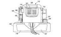
本発明は、モジュール性を有し、携帯可能であり、改良された機能性を有する透析ユニットに関する。図1及び図2において、1の実施形態では、透析システム100、200は、ベース202に着脱可能に取り付けられたトップユニット101、201を備え、該ベース202は液体を貯蔵するための貯蔵部122、222を備える。トップユニット101、201は主ユニット或いはコントローラユニットとも称され、グラフィカルユーザインターフェース114、214と、ポンプユニットと、後述の電磁ロック及び機械的バックアップ機構を有するドア110、210とを備える。トップユニット101、201の一方の側には、透析装置103を着脱可能に固定する金具105が設けられている。トップユニット101、201の他方の側には、吸着剤カートリッジ107を着脱可能に固定するための吸着剤カートリッジ固定基板104、204が設けられている。図3に示すように、金具105、血液ろ過器103、吸着剤カートリッジ固定基板104、及び吸着剤カートリッジ107は、トップユニット101に対して同じ側に設けられても良い。何れの場合であっても、吸着剤カートリッジを支持し、注入液瓶を支持し、こぼれたものを受け止め、また/或いは漏出したものを漏出検出器へ導くための棚が、トップユニットの側方に形成されるよう、ボトムユニットはトップユニットよりも十分に大きな領域を有する。 The present invention relates to a dialysis unit that is modular, portable and has improved functionality. 1 and 2, in one embodiment, the
透析装置103とドア110との間には、抗凝固剤ポンプとしての注射器ポンプ190が設けられている。トップユニット101は、ボトルホルダハウジング内にボトルを下向きに収容するためのスパイクつきのベースを有するボトルホルダ190を備えても良い。輸液線は、血液ポンプの流入口、血液ポンプの流出口、又は透析装置の流出口(血液側)に接続される。輸液線は、抗凝固剤が空になったり、詰まったことを検出できるように、気泡検出器の中を通過してもよい。 Between the
本発明による透析システムは、従来技術よりも格段に優れた機能パラメータ及び操作パラメータを実現する。トップユニットは約20〜40ポンドの範囲であり、より具体的には30ポンドである。ボトムユニットは約15〜30ポンドの範囲であり、より具体的には22ポンドである。これは、従来のシステムより軽い。トップユニットは約1〜4立法フィートの範囲であり、より具体的には2.3立方フィートである。ボトムユニットは約1〜4立方フィートの範囲であり、より具体的には2.8立方フィートである。これは、従来のシステムと比較して容積が小さい。 The dialysis system according to the present invention realizes functional parameters and operational parameters that are much better than the prior art. The top unit ranges from about 20-40 pounds, more specifically 30 pounds. The bottom unit is in the range of about 15-30 pounds, more specifically 22 pounds. This is lighter than conventional systems. The top unit ranges from about 1 to 4 cubic feet, more specifically 2.3 cubic feet. The bottom unit is in the range of about 1 to 4 cubic feet, more specifically 2.8 cubic feet. This is a small volume compared to conventional systems.
1の実施形態では、図17に示すように、ユーザインターフェースとコントローラとを有するトップユニット1701は、スケールを内蔵する貯蔵部を有するベースユニット1702と奥行きは同じであるが、長さと高さが異なる。当該実施形態では、トップユニット1701とボトムユニット1702の奥行きDは、何れも10〜30インチの範囲であり、より好ましくは約19インチである。当該実施形態では、トップユニット1701の長さLtは、6〜20インチの範囲であり、より好ましくは約14インチである。一方、ボトムユニットの長さLbは14〜40インチの範囲であり、より好ましくは27インチである。当該実施形態では、トップユニット1701の高さHtは7〜21インチの範囲であり、より好ましくは約14.5インチである。一方、ボトムユニットの高さHbは3〜11インチの範囲であり、より好ましくは7インチである。 In one embodiment, as shown in FIG. 17, a
ベースユニット1702は更に、一対のショルダー1704によって定義されてもよい。各ショルダー1704は、中央に位置するトップユニット1701の側方からベースユニット1702の長さ方向に沿って外側に延びている。トップユニットは、ベースユニット1702の長さLbの中央に配置されるのが好ましい。従って、各ショルダー1704の長さは、4〜10インチの範囲であり、より好ましくは7インチである。ベースユニット1702の表面であって、ショルダー1704がトップユニット1701と物理的にぶつかる箇所からは、リップ1703が上方に向かって延びている。リップ1703の表面は、トップユニット1701の位置決めに使われる。リップ1703は、トップユニット1701のベースの周囲に沿って連続していて、トップユニット1701と同じ長さと奥行きを有する。また、その高さはHt2とHtとの差に等しい。1の実施形態では、リップの高さは0.1〜3.5インチの範囲であり、より好ましくは0.6インチである。システム全体の高さHt3は10〜35インチの範囲であり、より好ましくは22インチである。
トップユニット1701及びベースユニット1702を形成する外ハウジングの構成は、4つの側面、上面、下面を有する直方体、立法体、或いは箱形とされる。1の実施形態では、トップユニット1701とベースユニット1702のそれぞれにおいて、4つの側面の内の2つの側面は、それぞれが内面と外面を備え、同じ高さと長さと奥行きを有する。また、上面及び下面は、それぞれが内面と外面を備え、同じ高さと長さと奥行きを有する。 The configuration of the outer housing forming the
なお、図1、図2、図17a、及び図17bに示すシステムの構成は単なる一例であって、本発明はこれに限定されない。例えば、図3において、トップユニット301は、ベースユニット302の上であって、ベースユニット302の全長に対して中央に配置される(ベースが対称)のとは対照的に、ベースユニット302の一方の側に配置されてもよい(ベースが非対称)。トップユニット301をベースユニット302の片側に配置させると、全てのチューブ接続及び消耗品をシステムの同じ側に配置できるという利点があるが、吸着剤カートリッジ317や透析装置313が不必要に密集してしまい、装置の使い勝手が悪くなる。 In addition, the structure of the system shown in FIG.1, FIG.2, FIG.17a and FIG.17b is a mere example, and this invention is not limited to this. For example, in FIG. 3, the
この透析システムは、従来のシステムと比較して、使用する水の量が少ない。従来のシステムでは、1回の処置あたり、約120リットル使用していた。1の実施形態におけるシステムでは、3〜8リットル、より具体的には5〜6リットル使用される。更に、このシステムは、余分な水を処理するための家庭用の排水施設、供給用接続、別個の排出口の何れも必要としない。 This dialysis system uses less water than conventional systems. Conventional systems use about 120 liters per treatment. The system in one embodiment uses 3-8 liters, more specifically 5-6 liters. In addition, the system does not require any domestic drainage facility, supply connection, or separate outlet for treating excess water.
加えて、本発明の実施形態では、多重パス吸着システムを採用する。当該システムは、XCORP212に開示され、また、参照することによりここに盛り込まれている。従って、このシステムは逆浸透システムによる別個の精製水供給装置は必要でないし、これに代えて通常の水道水を吸着システムで精製して使用できる。 In addition, embodiments of the present invention employ a multi-pass adsorption system. The system is disclosed in
更に、このシステム設計は、小型且つ省エネであり(最大で300、施術中は50〜100Wのみ)、内蔵ポンプや、移動或いはプライミングのための別個の液袋が不要である。この装置は、20〜600Qb(ml/分)の範囲の血液流及び50〜500Qd(ml/分)の透析液流で作動する。容積の正確度は正確で、±30ml/時未満である。 Furthermore, this system design is small and energy saving (up to 300, only 50-100W during the procedure), and does not require a built-in pump or a separate fluid bag for movement or priming. The device operates with a blood flow in the range of 20-600 Qb (ml / min) and a dialysate flow of 50-500 Qd (ml / min). The volumetric accuracy is accurate, less than ± 30 ml / hour.
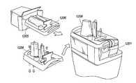
図2に示されるように、透析システムはモジュール性を有する。1の実施形態では、トップユニット201をボトムユニット202から物理的に分離できる。トップユニット201はシステムの主電子装置を収容していて、当該主電子装置は、自足ハウジングとして一体形成されたグラフィカルユーザインターフェースと、コントローラと、ポンプとを有する。より大きなボトムユニット202は貯蔵部222を収容する。システムの電子装置と貯蔵部とを離したことで、携帯透析システムを組立や点検、或いは持ち運びのために複数のユニットへ分解することができ、各サブユニットの取り扱いや梱包、持ち運びが容易になる。この設計では、UPSや他の宅配業者により出荷できるよう、各部品のサイズを具体的に設定している。これは、更に生産の伸びにおいても柔軟性がある。例えば、コントローラユニット或いは貯蔵部(液体体積の減少や容積測定の変更)に対して別個に改良が行われた場合、既存の顧客はこれら2つの構成部品の両方についてアップグレードする必要はなく、一方に対してのみ行えばよい。同様に、もし、2つの構成部品のうち、一方のみが故障した場合(例えば、ポンプが消耗した場合)、顧客は一方の構成部品についてのみ修理依頼したり、購入したりすればよい。 As shown in FIG. 2, the dialysis system is modular. In one embodiment, the
このようなモジュール性を可能にするため、本発明の実施形態ではラッチ機構を採用する。1の構成においては、当該ラッチ機構はボトムユニット202をトップユニット201にしっかりと固定するものであって、当該ラッチ機構を操作することによりボトムユニット202をトップユニット201から取り外すことができる。ラッチを使わず、単にこれら2つのシステムを上下に積み重ねることもできるが、ラッチを用いることにより、これらが不意に外れてしまうことを防止できる。更に、ラッチで固定すれば装置を移動しやすい。このラッチ機構は、単に上部材及び下部材に設けられた雄型雌型コネクタを採用し、工具を必要としないものであるのが好ましい。また、ラッチ機構は、上部材と下部材間の位置合わせを確実に行える設計であるのがより好ましい。これにより、これらユニットの位置あわせが適切に行われると自動的に電源回路と接続して当該回路を完成させる電子装置(後述するように、トップユニットの下側及びボトムユニットの上側に露出されたもの)の使用が可能になる。これにより、単一の電力供給装置の使用及び簡素な接続/遮断が可能になる。 In order to enable such modularity, the embodiment of the present invention employs a latch mechanism. In the first configuration, the latch mechanism firmly fixes the
図14において、ボトムユニット1402は、4つの側1405a、1405b、1405c、1405dと、ベースと、上面1406と、第1の側1405dからアクセス可能な貯蔵部1422とを有する。ボトムユニット1402の上面1406には、複数のラッチ結合構造1420が設けられている。1の実施形態では、2つのラッチ結合構造1420a、1420bが設けられていて、重量配分が均等となるように、これらはボトムユニット1402の長さ方向中央に配置されている。第1のラッチ結合構造1420aは、ボトムユニット1402の幅の1/3と等しい距離だけ側1405dから離れた位置に配置されるのが好ましい。第2のラッチ結合構造1420bは、ボトムユニット1402の幅の1/3と等しい距離だけ側1405bから離れた位置に配置されるのが好ましい。 In FIG. 14, the
ラッチ機構は、図15に示されるように、例えばボルトやネジ、その他の留め具1502によってボトムユニット1505の上面に固定された金属枠1501を備える。枠1501は、ラッチ内に脱可能に柔軟に挿入される突起或いは長尺部材1503を支持する。 As shown in FIG. 15, the latch mechanism includes a
ボトムユニットをトップユニットに対して着脱可能にしっかりと固定するため、トップユニットには、トップユニットのベースにしっかりと固定された補助機械的スライドラッチを備える。1の実施形態では、トップユニットのベースには第1のラッチが設けられている。この第1のラッチは、トップユニットの長さ方向中央であって、第1の側からトップユニットの幅の1/3の距離だけ離れた位置に配置されるのが好ましい。このベースには第2のラッチも設けられていて、これはトップユニットの長さ方向中央であって、第1の側に対して反対側かつ平行な第2の側からトップユニットの幅の1/3の距離だけ離れた位置に配置されるのが好ましい。 In order to firmly and detachably fix the bottom unit to the top unit, the top unit includes an auxiliary mechanical slide latch firmly fixed to the base of the top unit. In one embodiment, the base of the top unit is provided with a first latch. The first latch is preferably arranged at the center in the length direction of the top unit and at a distance of 1/3 of the width of the top unit from the first side. The base is also provided with a second latch, which is the center of the top unit in the longitudinal direction and is 1 side of the width of the top unit from the second side opposite and parallel to the first side. It is preferable that they are arranged at positions separated by a distance of / 3.
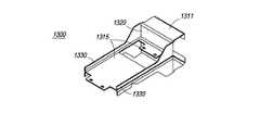
図13に示されるように、トップユニットは、金属性平型スライドベース1315を有するラッチ1300を備える。レール1330は、トップユニットの下面と摺動自在に係合する。トップユニットの下面には、レール1330を所定位置に保持するための結合部材が設けられている。ラッチ1300は、ベースユニット1406の上面に物理的に取り付けられた結合構造の内側及び外側に向かってスライドする2つのラッチタブ1315を有する。 As shown in FIG. 13, the top unit includes a
トップユニットに取り付けられたラッチ1300は、ボトムユニット1406の上面のラッチ結合構造1420a、1420bと結合する。作動時において、スライドラッチ1300が第1の位置にあるとき、スライドラッチ1300はラッチ結合構造1420a、1420bと物理的に正しく結合しないため、トップユニットはベースユニットの上にぴったり収まらず、或いはベースユニットに対して位置が揃わない。トップユニットをベースユニット1406の上面に適切に搭載するためには、トップユニットの底に配置された部材支持構造内においてスライドラッチを第2の位置まで移動させる。 The
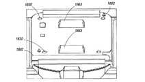
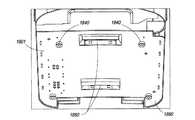
第2の位置では、ラッチ1311のハンドルが突出し、これによりタブ1315をラッチ結合構造1420a、1420bから離れる方向に移動させ、トップユニットをベースユニット上に正しく配置できる。図18a、図18bにおいて、スライドラッチ1880を備えるトップユニット1801は、トップユニット1801の底に設けられた4個の小さなゴム脚、或いは足パッド1840によりボトムユニット1802に対して位置決めされる。これらのパッド1840は、ボトムユニット1802の上部の角付近に設けられた4つの空洞或いは窪み1830内にぴったりと確実にはめ込まれるように構成されている。加えて、トップユニット1801は、ベースユニット1802の上面に設けられたピン1860或いは突起により、ボトムユニット1802に対して正確に位置決めされる。これらのピン1860は、トップユニット1801の下面に設けられた空洞1890にぴったりと確実にはめ込まれるように構成されたものである。ボトムユニットは、上述したように、ラッチ結合構造1863を更に有する。 In the second position, the handle of the
ゴム脚1840及びピン1860を、空洞1830及び空洞1880とそれぞれ位置合わせすることにより、何度も失敗を繰り返すことなく、ラッチ結合構造1863に対してトップユニット1801のラッチ1880を容易に位置合わせして結合させることができる。一端位置あわせが行われれば、ラッチ1880をラッチ結合構造1863内へスライドさせるだけで、ラッチ1880をラッチ結合構造1863に結合でき、これにより2つのユニットを強固に固定できる。図13及び図14に戻り、結合を解除するためには、ラッチハンドル1311を引くか、或いは操作して、ベースユニットスロット1420a、1420bからタブ1315を開放する。これにより、上方のトップユニットを下方のボトムユニットから持ち上げることができる。 By aligning the
更に、上述したモジュール性を実現するために、本発明の実施形態では、電気通信接続機構を採用している。これは、1の構成では、ボトムユニットとトップユニット間の電気通信及び/又はデータ通信接続を確実に確立するものであり、他の構成においては、ボトムユニットとトップユニット間の電気通信及び/又はデータ通信接続を遮断するものである。 Furthermore, in order to realize the modularity described above, an embodiment of the present invention employs a telecommunication connection mechanism. This ensures that in one configuration the telecommunication and / or data communication connection between the bottom unit and the top unit is established, and in another configuration the telecommunication between the bottom unit and the top unit and / or The data communication connection is cut off.
図16において、トップユニットとボトムユニット間の電気接続は、トップユニットがボトムユニット上に設置された時点で確立される。これらの接続は、ボトムユニット1605の上面に留め具1601を用いてしっかりと固定され、一体的に板1602として構成された非接触赤外線通信ポート1603及び押しピン電源ポート1603により確立される。なお、トップユニットの下面は、押しピンに対して整列配置された電気導体パッドを有する。また、押しピンと導体パッドは逆の配置であってもよい。つまり、押しピンをトップユニットの下面に、導体パッドをボトムユニットの上面に配置してもよい。In FIG. 16, the electrical connection between the top unit and the bottom unit is established when the top unit is installed on the bottom unit. These connections are established by a non-contact
1の実施形態では、トップユニットの下面に一体的に設けられた6つのバネ仕掛けのピンを導体パッドと電気的に接続することにより、高電流電力接続が確立される。3つのピンは+24ボルトDC電流用で、他の3つのピンは接地用である。1の実施形態において、ピン或いはプローブは次の特徴を有する。a)センタは最低で0.175インチ、b)15アンペアの定格電流(定常)、c)0.06インチ〜0.067インチのトラベル量で、6.2オンス〜9.0オンスの範囲のスプリング力、d)標準で10mΩ未満の抵抗、e)最大トラベル量は0.09〜0.1インチの範囲、f)ワークトラベル量は0.06インチ〜0.067インチの範囲、g)金メッキされたニッケル/シルバー製のバレル、h)ステンレス製のスプリング(オプションで金メッキされていても良い)、i)硬質ベリリウム銅製で金メッキされたプランジャー、j)オプションで、ステンレス製のバイアスボール。ピンのスプリング力は、曲げやねじれ等を吸収することにより破損を防ぐ。尚、電気ピンとは、電力を伝達可能なあらゆる突起を示すものであり、電気接触パッドとは、電気ピンを支持可能なあらゆる面を示すものである。 In one embodiment, a high current power connection is established by electrically connecting six spring-loaded pins integrally provided on the lower surface of the top unit to the conductor pads. Three pins are for +24 volt DC current and the other three pins are for ground. In one embodiment, the pin or probe has the following characteristics. a) Center is at least 0.175 inches, b) Rated current of 15 amps (steady), c) Travel range of 0.06 inches to 0.067 inches, in the range of 6.2 ounces to 9.0 ounces Spring force, d) Resistance less than 10mΩ as standard, e) Maximum travel amount in the range of 0.09 to 0.1 inch, f) Work travel amount in the range of 0.06 inch to 0.067 inch, g) Gold plating A nickel / silver barrel, h) a spring made of stainless steel (optionally gold-plated), i) a plunger gold-plated with hard beryllium copper, j) an optional stainless steel bias ball. The spring force of the pin prevents damage by absorbing bending and twisting. In addition, an electric pin shows all the protrusions which can transmit electric power, and an electric contact pad shows all the surfaces which can support an electric pin.
非接触赤外線通信ポート1603は、トップユニットの下面に設けられた2つのLED発光部及び2つのLED受光部に対して整列配置されて接続される2つのLED発光部及び2つのLED受光部を採用する。発光ポートと受光ポート間の距離は0.3インチ未満である。ボトムユニットの上面及びトップユニットの下面のどちらにおいても、4つのLEDユニットは、制御ペア(1の発光部と1の受光部とを備える)と安全ペア(1の発光部と1の受光部とを備える)の、2組のペアに分かれている。これらのポートは、トップユニットとボトムユニットが適切に配列された際、データ通信状態とされる。1の実施形態では、LED発光部はGaA1Asダブルヘテロ構造の870nm高速赤外線発光ダイオードである。LED発光部は次の特徴を有する高速ダイオードである。a)超高放射力、b)低順電圧、c)高パルス電流稼動に適する、d)半分強度の角度(angle of half intensity)は約17度、e)ピーク波長は約870nm、f)逆電圧は約5V、g)順方向電流は約100mA、h)ピーク順方向電流は約200mA、i)順サージ電流は約0.8A、j)ワット損は約190mW、接合部温度は約100℃、l)作動温度範囲は−40〜85℃。尚、非接触赤外線通信ポートは、ボトムユニットの上面或いはトップユニットの下面に亘って、あらゆる機能的な方法で配置することができる。また、異なる周知の通信ポートや構造を採用することも可能である。 The non-contact
1の実施形態では、LED受光部は高速シリコン光ダイオードであって、超高速応答時間を有し、放射有感領域が約0.25mm2、半分強度の角度が約15度である。In one embodiment, the LED receiver is a high-speed silicon photodiode with an ultra-fast response time, a radiation sensitive area of about 0.25 mm2 and a half-intensity angle of about 15 degrees.
LED受光部は次の特徴を有する。a)逆電圧は約60V、b)ワット損は約75mW、c)接合部温度は約100℃、d)作動温度範囲は−40〜85℃、e)順電圧は約1V、f)最低降伏電圧は60V、g)ダイオード容量は1.8pF。 The LED light receiver has the following characteristics. a) Reverse voltage is about 60V, b) Power dissipation is about 75mW, c) Junction temperature is about 100 ° C, d) Operating temperature range is -40 to 85 ° C, e) Forward voltage is about 1V, f) Minimum breakdown Voltage is 60V, g) Diode capacitance is 1.8pF.
図1、図2、図3に戻ると、コントローラユニット101、201の上部には、ハンドル211、311及び作業スペースとしての使用可能棚112、212が設けられている。システムの上ポンプ部に設けられたハンドルは、システムの内枠又は内部構造に直接接続されていて、トップユニット101、201を包囲するプラスチック製の外部形成、ハウジング、或いは外板から単に突出している訳ではない。システムの内枠に直接接続されることで、ハンドルを用いてシステムを安全に移動させることができ、特に、器具が6リットルの水を収容した状態(約40ポンドの加算)で作動する際の負荷に対して確実に対処できる。 Returning to FIGS. 1, 2, and 3, handles 211, 311 and
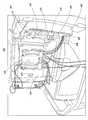
図5において、1の実施形態では、トップユニット501は内金属ケース、枠、或いはハウジング510を備え、ここに、電子機器、コントローラ、及び他のトップユニット構成部材が収容される。内ケース510は、トップユニット501の後側へ延びる水平突アーム507を備える。略水平トップ棚505は、トップ棚構造505と一体形成された少なくとも1のハンドル520と、ベースブラケット530と、垂直アーム506とを備え、これにより1の連続した金属片或いは成型プラスチック片を構成している。ベースブラケット530はトップユニット501の前部分で内ケース510にしっかりと取り付けられていて、垂直アーム506はネジによりポイント508で突アーム507にしっかりと取り付けられている。トップユニット501の内ケース510に対して棚505及びハンドル520構造をしっかりと取り付けることにより、トップユニットの外ケースとハンドルとの接続箇所に大きな重荷負荷がかかることにより起こる潜在的な損傷或いは破損を防止できる。 In FIG. 5, in one embodiment, the
また、内枠或いは内ケース510には、図1に示すドア110の内枠を構成する金属ドア562が、蝶番565によって取り付けられている。ドア562は内枠510の一部である板561にしっかりと取り付けられている。構造563及び572は、内モータ・プーリーアセンブリを保持する構造であり、又/或いは当該アセンブリの突出部を示すものである。フレーム510の後方から延びる突起583は、パワーエントリーモジュールやUSB接続582を含む種々の電子部品の接続に用いられる。 Further, a
コントローラユニットの上部或いは棚505は平坦で、側壁を有し、補充品の収容や一時的な作業面として理想的である。図12において、1の実施形態では、システムで使用される消耗品1206は、トレイ1205上で組み立てられた状態で梱包されて出荷される。トレイ1205はコントローラユニット1201の作業スペース上に置かれる。これにより、必要な消耗品へのアクセス及び当該消耗品の管理が容易となる。これは、家庭ユーザにとって特に重要なことである。コントローラユニット1201は、液漏れに備えて防水加工されていて、漏れた液がトップコントローラユニット1201内に染み込んでこれを破損しないようにされている。 The top or
コントローラユニット1001の他の構造的特徴を図10に示す。ユニット1001は、消耗部品のコードやタグを読み取るバーコードリーダやRFIDタグリーダ等の内蔵型露出リーダ1005を有するのが好ましい。操作に際し、ユーザは消耗部品に付された全コード或いはタグをリーダに通すのが好ましい。最初のGUI透析セットアップステップにおいて、ユーザに各消耗部品をリーダに通すように指示して、ユーザに当該作業を行うように促すことができる。 Another structural feature of the
これにより、リーダは消耗品の識別情報を取得し、当該識別情報をメモリに記憶された内部テーブルへ送り、内部テーブルの内容と識別情報とを比較し、適切な消耗部品(特に、透析液の添加物)であることを認証する(或いは認証しない)。内部テーブルの内容は消耗品の名称や量を手入力することで生成されても良いし、消耗品の名称及び量を詳述する処方箋へ遠隔アクセスすることで生成されても良い。この認証ステップには、少なくとも2つの利点がある。1つ目は、ユーザが必要とされる部品を全て所有していることを確認できることであり、2つ目は、正しい部品(偽造品や不適切な消耗品でないもの)が使用されていることを確認できることである。 As a result, the reader acquires the identification information of the consumables, sends the identification information to the internal table stored in the memory, compares the contents of the internal table with the identification information, and selects the appropriate consumable component (particularly the dialysate solution). It is certified (or not certified) that it is an additive. The contents of the internal table may be generated by manually entering the name and quantity of the consumables, or may be generated by remotely accessing a prescription that details the name and quantity of the consumables. This authentication step has at least two advantages. The first is to confirm that the user has all the required parts, and the second is that the correct parts (not counterfeit or inappropriate consumables) are used. It can be confirmed.
他の実施形態では、トップユニットの側方に搭載されたリーダ1005は、特殊多機能赤外線カメラであって、あるモードではバーコード読取可能であり、他のモードでは注入液容器内のレベル変化を検出可能である。このカメラは、赤外線信号を出力し、当該信号は液面で反射される。反射された信号はカメラの赤外線受信部で受信され、プロセッサで処理されて液面のメニスカスの位置が検出される。1の実施形態では、カメラは、0.02mmの解像度で液面の変化を検出してモニタする。1の実施形態では、カメラは1.3メガピクセル単一チップカメラモジュールであって、以下の特徴のうち、1又は複数の特徴を有する。a)1280H×1024V能動ピクセル、b)3.0μmサイズ、c)1/3インチ光フォーマット、d)RGBバイエル色フィルタ配列、e)統合10ビットADC、f)欠陥補正、レンズシェーディング補正、画像スケーリング、デモザイシング、鮮明化、ガンマ補正、及び色空間補正を含む、統合デジタル画像処理機能、g)自動露出制御用の内蔵カメラ制御部、自動ホワイトバランス制御、黒レベル補正、h)プログラム可能なフレーム率及び出力軽減機能、i)最大15フィート/秒SXGA順次走査、j)低出力30フィート/秒VGA順次スキャン、k)8ビットパラレルビデオインターフェース、l)2線シリアル制御インターフェース、m)オンチップPLL、n)2.4〜3.0Vのアナログ電力供給、o)単独I/O電力供給、p)パワースイッチを有する統合電力管理、q)24ピンシールドソケットオプション。1の実施形態では、カメラはSTマイクロエレクトロニクス製の1.3メガピクセルカメラ(モデル番号VL6624/VS6624)である。 In another embodiment, the
透析システムのトップユニット或いはボトムユニットは、ネットワークへ直接接続できるよう、イーサネット接続やUSBポート等の電子インターフェースを更に備えるのが好ましい。これにより、遠隔処方箋認証、コンプライアンス警戒、及び他の遠隔サービス業務を促進できる。USBポートは、血圧モニタやヘマクリット値/飽和モニタ等の付属品への直接接続を可能にする。インターフェースは電子的に孤立していて、これによりインターフェース装置の質に関係なく、患者の安全を確実にできる。 The top unit or bottom unit of the dialysis system preferably further comprises an electronic interface such as an Ethernet connection or a USB port so that it can be directly connected to the network. This can facilitate remote prescription authentication, compliance alerts, and other remote service operations. The USB port allows direct connection to accessories such as blood pressure monitors and hematocrit / saturation monitors. The interface is electronically isolated, thereby ensuring patient safety regardless of the quality of the interface device.
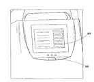
トップユニットの前部には、システム100の簡単ユーザインターフェースを提供するグラフィカルユーザインターフェース114が設けられている。家庭においては、簡単に装置を使用できることが重要である。色及びタッチスクリーンを最大限利用するのが、有用性の観点から望ましい。タッチスクリーンは、複数のユーザ入力構造を可能にし、複数の言語に対応でき、(特に、明るさ調整及び暗視色を用いることで)夜間においても視認しやすい。GUIは更に、動作中におけるドアの自動開閉及び自動ロック機能を有する。1の実施形態では、GUIはドアを第1ラッチ位置まで開放し、次にユーザが物理的なドア開放ボタンを押すとドアが全開する。他の実施形態では、装置には、ドアを手動で開けるために、(ドア開放ボタンを2回、或いは強く押すことで)ユーザがドアを開けられるようにする手動オーバーライドが設けられている。図8において、GUI800の近傍には、電球付き可視指示を備える機械ボタン805が1つ設けられるのが好ましい。これは、起動すると、動作状態に係わらず、普通の機能(例えばシステムの停止機能)を有する中央停止ボタンを提供する。 At the front of the top unit is a
図1において、貯蔵システム102はドア118を有する。ドア118を引くと、貯蔵部122が引き出され、貯蔵部へのアクセスが可能となる。貯蔵部の容量はスケールシステムでモニタされる。スケールベースの液体秤600を図6に、より詳細に図7a及び図7bに示す。この秤600には貯蔵部が一体形成されていて、正確な液体消費データを提供し、正確な残量計算を可能にする。これにより、体液の不均衡に起因する低血圧症やその他の病気を防止する。スケールと貯蔵部とを一体形成してこれらを完全に囲むことにより、より丈夫なシステムを提供できる。 In FIG. 1, the
図7aに、貯蔵システムの内部構造700を示す。金属内枠720は2つの側方721と、後方722と、開放された前方723と、底724とを有する。内部構造又は内枠を示すが、ここでは図1で部材102として示される外ハウジングは省略する。スケール718は貯蔵部内部構造700に一体的に形成されている。スケール718の下面715は金属面或いは受け皿を備え、これはスケール718の残りの部分と共に、4つの屈曲部705によって外貯蔵部ハウジング(図1の102)からつり下げられている。スケールの下面715の下方には、加温パッドが設けられることが好ましい。この加温パッドは、温度を上昇させてこれを熱として面715へ伝達できる四角形、長方形、円形、或いは他の形状の面を有する。フィールドを有し、当該フィールドにおける変化を利用して伝導性を測定できる伝導コイル770が底面715に一体形成されている。従って、貯蔵袋(図示せず)が下面715上に置かれると、貯蔵袋はコイル770に接触するため、加温パッドにより加熱されて、その伝導性がモニタされる。 FIG. 7a shows the
側方721の内面は、貯蔵袋が取り付けられるプラスチックシート等の使い捨て貯蔵袋搭載面710に対し、固定、保持、包装、或いは取り付けられるための複数のレール、長尺部材、或いは突起719を備える。具体的には、面715に搭載された貯蔵袋の排出口を、シート710に一体的に設けられた導管に取り付けられる。スケール面718の四隅には屈曲部705が搭載されていて、各屈曲部705はホールセンサと磁石とを備える。 The inner surface of the
図7bにおいて、屈曲部705は複数の固定ポイントを有し、ここで屈曲部が外貯蔵ハウジングに固定される。屈曲部は更に、磁性体762(例えば2個の磁石)とホールセンサ764とを備える。屈曲部705のベース767はスケール718の上面715に取り付けられている。負荷がかけられたスケール718が変位すると(例えば、貯蔵袋が透析液で満たされると、袋は面715を押し下げ、スケール718を下方に変位させると)、一端がスケールに接続され他端が外ハウジングに接続された屈曲部705が動き、屈曲部の一端に搭載された磁石762が、磁性体762の磁界における変化を利用してこの動きを追跡する。ホールセンサ764は磁界強度における変化を検出する。このように検出された磁界強度の変化に基づく重量負荷の計測方法は、当業者にとって自明である。 In FIG. 7b, the
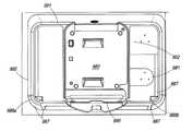
透析装置103や吸着剤カートリッジ107、注入液等の使い捨て部材を、アクセスしやすい形態でシステムの外部に配置することにより、サイズの異なる吸着剤カートリッジや透析装置、注入混合液の使用が可能になり、使用における柔軟性及びシステムの適用性を改善できる。図3及び図9において、使い捨て部材、特に、完全に使い捨ての血液回路及び透析液回路は、キット(透析液、マニフォールド、チューブ、貯蔵袋、アンモニアセンサ、及び他の部品を含むもの)の中に梱包され、トップユニット301の前ドア(上述)303を開け、プレッシャーやセンサ、その他の非使い捨て部品に対して正しく位置あわせが行われるよう、透析装置313及びマニフォールド304をインストールすることで、使用される。前ドア303の内面に一体形成された複数のポンプシュー305により、使い捨て部品の搭載が容易にできる。マニフォールドを挿入するだけでよく、ポンプチューブをローラとシュー305との間に通す必要がない。このような梱包及び簡単な取り扱いにより、消耗品の装着及びシステムの清掃を容易にできる。また、図11に示す液体回路は適切に構成され、使用可能な状態にされている。作動時には、トップユニット301は、貯蔵部322を備えるボトムユニット302に取り付けられる。 Disposable members such as the
消耗品を装着するために、前ドアは大きく開放される(約100度)。大きく開放することにより、マニフォールドの装着が容易にできると共に、装置面やドア内部の清掃を容易にできる。ドアを閉めて装置の可動部材を覆うことにより、安全かつ頑丈にできる。これは、家庭内使用において特に重要である。更に、前ドアにディスプレイを収容することにより、スペースを節約できると共に、消耗品が装着されてドアが閉まった状態でなければ装置を作動すべきでないという重要事項を強調できる。ドアによって、マニフォールド及びポンプセグメントに対して必要な閉塞力が加えられる。ドア面には更に、タッチスクリーン、音声アラーム、手動停止ボタンが収容されている。 In order to mount the consumables, the front door is greatly opened (about 100 degrees). The large opening makes it easy to mount the manifold and facilitates cleaning of the device surface and the inside of the door. By closing the door and covering the movable member of the device, it can be made safe and sturdy. This is particularly important for home use. In addition, storing the display in the front door saves space and highlights the important fact that the device should not operate unless the consumables are installed and the door is closed. The door provides the necessary occlusion force for the manifold and pump segment. The door surface further contains a touch screen, an audio alarm, and a manual stop button.
1の実施形態では、ドアは電動ステッピングモータにより完全に閉じた状態に保持される。このモータはユーザインターフェースを介して操作され、特に、ドアを完全に閉じたり開けたりできる状態でユーザがボタンを押すことにより操作される。ドア及びポンプシューによりマニフォールド構成に適切な圧力が加えられるよう、ドアを閉めると共にドア閉力を十分に生成できる電子機構を備えるのが好ましい。1の実施形態では、90〜110ポンドのドア閉力が生成される。 In one embodiment, the door is held fully closed by an electric stepping motor. This motor is operated via a user interface, in particular when the user presses a button with the door fully closed or open. It is preferable to provide an electronic mechanism that can close the door and generate a sufficient door closing force so that the door and pump shoe can apply appropriate pressure to the manifold configuration. In one embodiment, a door closing force of 90-110 pounds is generated.
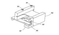
1の実施形態における電動ドア閉機構1100を図11aに示す。ステッピングモータ1106は主ネジ1116に機械的に接続されていて、コントローラにより起動されると、ステッピングモータ1106が主ネジ1116を回し、これによりロッド1118からフックに駆動力が与えられる。部材1140の下方に配置されたフックは、U型ラッチ1130にラッチするようにされていて、引っ張られたり回転したりしてステッピングモータ1106の方向へ移動すると、閉方向にU型ラッチ1130を引っ張って、必要なドア閉力を与える。フックはロッド1118と物理的に係合していて、これを操作することにより、U型ラッチ1130を引っ張ってしっかりと閉じたり、U型ラッチ1130との係合を緩くできる。電動閉システムは、搭載ブラケット1105により適切な向きに維持されて搭載される。 An electric
操作上、ユーザがドアを十分に閉じると、ドアに設けられたU型ラッチ410は、図4に示すようにコントローラユニットの内部に設けられたフック450と係合する。そして、ユーザは、好ましくは機械的ボタン或いはグラフィカルユーザインターフェースを介して、携帯透析装置に対してドアを閉めるよう指示を出す。機械的ボタン或いはグラフィカルユーザインターフェースが押されると、コントローラに対して信号を送り、コントローラはステッピングモータ1106を起動する。ステッピングモータ1106は駆動力をフック450へ供給し、フック450は係合しているU型ラッチ1130、410を引っ張り、しっかりと閉じる。1の実施形態では、コントローラはモータにより付与されるトークを監視し、その値が所定値に達すると、ステッピングモータを停止させる。他の実施形態では、主ネジ近傍に配置されたホール装置が主ネジの伸長を検出し、ネジの移動量を判断する。ネジがドア閉力を増大させる方向に十分に移動すると、ホールセンサはコントローラに対して信号を出力してモータを停止させる。或いは、センサはネジの伸長を示す信号を常に出力し、コントローラがこれを解釈して十分な駆動力が付与されたか否かを判断し、ステッピングモータを停止すべきかどうか判断する。何れの実施形態においても、モータのトークが過大になったり、所定距離を越えたり、所定時間内にドアが完全に閉じた状態に至らない場合には、コントローラはモータを停止させて全開状態まで反転させてもよい。更に、コントローラは視覚及び/又は音声アラームを発してもよい。 In operation, when the user closes the door sufficiently, the
ユーザがドアを開ける場合には、機械的ボタン又はグラフィカルユーザインターフェースアイコンを起動し、コントローラに信号を送ってステッピングモータ1106を逆方向に起動させる。すると、フックとU型ラッチとの係合がゆるむ。機械的開放ボタン1107が押下されると、U型ラッチとのゆるい係合が解かれる。 When the user opens the door, a mechanical button or graphical user interface icon is activated and a signal is sent to the controller to activate the stepping
必要な閉力を付与するのに加え、この電動ドア閉機構には重要な特徴がいくつかある。まず、障害物がドアに挟まるのを防止し、大きなドア閉力の対象となるのを防止する。図4において、マニフォールドはエッジガードに包囲されている。エッジガードは、人の指や不適切に装着された消耗品等の妨害物がドアとトップユニットの底板との間に挟まった際に、ドアラッチがトップユニットに設けられたラッチ受けと係合するのを防止するものである。ドア405は金属ケース425が取り付けられた内面406を有する。1の実施形態では、ドア405の内面406の上面はケース425の外面に対して固定されている。ケース425は略長方形状であって、内部容積を形成し4方の側407とベース408とを有する空洞を規定している。空洞は透析システム400のマニフォールド構成に向かって開放していて、マニフォールド構成430とガード440を取り囲む。ガード440は、マニフォールド430の上方及び側方を包囲するプラスチック幕であるのが好ましい。ベース408の面には、ポンプシュー415と、後板に向かって突出する少なくとも1のU型ラッチが取り付けられている。フック450はガードと一体形成されていて、ガードから外方に突出している。フック450は、U型ラッチ410としっかりと係合したり、その係合が解かれたりする。ドアが正しく閉められ、ドアとガードの間に何も挟まっていない状態においては、U型ラッチには電動ドアロックフック機構が機械的に接続する。もし、妨害物が挟まると、金属ケース425はトップユニットの内部容積内へ突出できず(ガードを包囲できず)、U型ラッチはフックと係合できない。従って、妨害物がある場合には、機械的な接続や、ドアが電動により不用意に閉まるのを防止する。 In addition to providing the necessary closing force, this electric door closing mechanism has several important features. First, an obstacle is prevented from being caught by the door, and is prevented from being subject to a large door closing force. In FIG. 4, the manifold is surrounded by an edge guard. The edge guard engages with the latch receiver provided on the top unit when obstructions such as human fingers or improperly worn consumables are caught between the door and the bottom plate of the top unit. This is to prevent this. The
次に、機械的ボタンリリース1107は、電動ドア閉力がステッピングモータの逆回転によって解かれた場合に限り起動される。これによりドアが不用意に開いたり、ドアが急速に開くのを防止している。図11a及び図11bにおいて、ドアが閉じられロックされると、ボタン軸1107上のコロ1150が90度回転し、押ピンを電動ドアロックフックから遠ざかる方向へ移動させる。コロ1150はロッド1121により回転される。ロッド1121は位置1145でコロと接続していて、主ネジ1116と機械的に接続されている。コロ1150にはバネが装着されていて、小ピンソレノイドによりロックされる。ユーザがロック位置のボタンを押すと、ボタンは装置内へ移動するが、コロの回転により変位するため、フックとの係合は解かれない。これによりドアが開くのを防止する。停電になったり、電源が意図せず遮断された場合には、ピンソレノイドが開放し、コロが90度戻り、押ピンが適切に配列する。次にユーザがボタンを押すと、押ピンは電動ドアフックと接触し、ドアラッチを開放する。この機構により、便利で安全な機械的ドアリリースのバックアップを提供でき、機械的ドアリリースが不用意に起動されてドアが過大な力で開放される恐れがない。なお、「フック」或いは「ラッチ」は物理的或いは機械的に他の突起或いは部材に対して係合可能な如何なる突起或いは部材を含む広い意味で用いられる。また、「U型ラッチ」とあるが、これに限定されず、上述したように、あらゆるラッチ機構或いはフック機構を用いることが可能である。 Next, the
上述したように、ボトムニットにより形成されトップユニットを包囲する棚空間は、区画漏出検出を可能にするため、装置内外の複数箇所に設けられた、液体センサを備える排水路を採用する。具体的には、光学漏出センサを備える排水路を、装置の外部部材に設けることにより、システムは外部材(吸着材容器など)から漏出した液体を捕らえて光学漏出センサへ送出することができる。 As described above, the shelf space formed by the bottom knit and surrounding the top unit employs drainage channels provided with liquid sensors provided at a plurality of locations inside and outside the apparatus in order to enable detection of compartment leakage. Specifically, by providing a drainage channel including an optical leakage sensor in an external member of the apparatus, the system can capture liquid that has leaked from an external member (such as an adsorbent container) and send it to the optical leakage sensor.
1の実施形態では、少なくとも3つの異なる光学漏出検出器がボトムユニットの外ハウジングに内側に設けられている。図9aにおいて、ボトムユニット902の上面は、若干傾斜していて、中央980は側方981、982よりも上方に位置している。1の実施形態では、面は中央領域980から側方981、982へ向かって、1〜10度、好ましくは3度の角度で下方に傾斜している。チャンネル987はボトムユニットの上面を取り囲み、外周に沿って延び、上面の中央を貫き、また/或いは上面の残りの部分を貫いて延びている。ボトムユニット902の上面が傾斜していることで、チャンネル987も中央980から側方981、982へ向かって傾斜する。他の実施形態では、上面は後方991から前面990へ向かう方向においても、やや下方に傾斜している。傾斜したチャンネル987は、液体をシステムの中央及び/或いは後方から遠ざけて、漏出検出器988が配置されている前方及び側方へ導き、チャンネル987と連通している。 In one embodiment, at least three different optical leak detectors are provided inside the outer housing of the bottom unit. In FIG. 9 a, the upper surface of the
第1の光学漏出検出器988aはボトムユニット902の上面の右前角部に配置されている。第2の光学漏出検出器988bはボトムユニット902の上面の前左角部に配置されている。各漏出検出器は、井戸或いは空洞の内部に配置され、井戸の側方に配置された光学センサを備える。光学センサは、漏れ出た液体及び/或いは井戸へ導かれた液体を検出し、検出信号をトップユニットのコントローラへ送信する。検出信号は、プロセッサで処理されて、漏出が発生したか否かが判断される。検出信号はその後記憶され、必要であれば、プロセッサはGUIに警報或いは警告を表示させる。井戸或いは空洞の底面は、ユーザが水気を拭き取り易いように、丸みを帯びているのが好ましい。図9bにチャンネル987及び井戸997内に配置された漏出検出器988aを備えるボトムユニット902の上面の詳細を示す。 The first
図9cでは、ボトムユニット902の内側に、より具体的にはスケール904を内蔵する貯蔵部903の内側に、追加の漏出検出器が少なくとも1つ配置されている。チャンネル905は、内ハウジング或いは金属袋ホルダ等の貯蔵構造と一体とされていて、一方の側から他方の側へ、或いは中央から両側へ向かって傾斜しているのが好ましい。1の実施形態においては、傾き角度は1〜10度の範囲であって、より具体的には3度である。漏出検出器を収容する井戸910は貯蔵ハウジングへと組み込まれていて、貯蔵ハウジングの片側或いは両側でチャンネル905と連通している。使い捨て袋で漏出が起こると、液体はチャンネル905を介して金属皿或いは貯蔵ハウジングの角部に流れ込み、漏出センサ910が配置される少なくとも1の井戸へ導かれる。 In FIG. 9 c, at least one additional leak detector is disposed inside the
排出路には2つの機能がある。a)液体が器具内部へ入り込むのを確実に防止する機能と、b)漏出を直ちに抑え、警報或いは警告を発するセンサへ確実に送るようにする機能である。また、装置は更に、装置内部の光学センサを有する井戸に繋がる液体排出チャンネルを有するのが好ましい。従って、例えば、内貯蔵部において漏出が発生した場合には、液体は重要な部材から離れる方向に導かれ、光学センサが漏出を知らせる。センサが起動すると、これに基づきGUIがユーザに対して警報を発し、液体漏出箇所を具体的に特定することができる。漏出検出を複数の独立区域(複数の液体センサ及び複数の排出経路)に分けることで、ユーザが漏出を素早く見つけだすことができる。複数のチャンネル及びセンサを設けたので、システムは部分的且つ自動的に漏出元を特定でき、問題解決に向けたグラフィックアシスタンスをユーザに提供できる。 The discharge path has two functions. a) a function that reliably prevents liquid from entering the instrument, and b) a function that immediately suppresses leakage and reliably sends it to a sensor that issues an alarm or warning. The device also preferably has a liquid discharge channel leading to a well having an optical sensor inside the device. Thus, for example, when a leak occurs in the internal storage unit, the liquid is guided away from the important member, and the optical sensor notifies the leak. When the sensor is activated, the GUI issues a warning to the user based on this, and the liquid leakage location can be specifically specified. By dividing the leak detection into a plurality of independent areas (a plurality of liquid sensors and a plurality of discharge paths), the user can quickly find the leak. By providing multiple channels and sensors, the system can partially and automatically identify the source of the leak and provide the user with graphical assistance for problem solving.
本発明の好適な実施形態について説明したが、種々の変更、変形が可能であることは当業者であれば理解できることであり、本発明の範囲を越えない限度で要素を代替品と入れ替えることも可能である。また、本発明の範囲を超えない限度で、具体的な状況や材料に適用できるように、本発明の特徴を様々な方法で変形することもできる。従って、本発明は上記実施形態に限定されるものではなく、本発明は請求の範囲に含まれるあらゆる実施形態を含むものである。 Although the preferred embodiment of the present invention has been described, it will be understood by those skilled in the art that various changes and modifications can be made, and elements may be replaced with alternatives without departing from the scope of the present invention. Is possible. In addition, the features of the present invention can be modified in various ways so that the present invention can be applied to specific situations and materials without exceeding the scope of the present invention. Therefore, the present invention is not limited to the above embodiment, and the present invention includes all embodiments included in the scope of the claims.
Claims (20)
Translated fromJapanese前記第1の外ハウジングの前側は前記コントローラユニットの内部容積へのアクセスを可能にするよう構成されたドアを有し、
前記第2の外ハウジングの前側は前記貯蔵ユニットの内部容積へのアクセスを可能にするよう構成されたドアを有し、
前記第1の外ハウジングの下側は、前記第2の外ハウジングの上側に対して着脱可能に固定されるように構成されていて、前記第1の外ハウジングが前記第2の外ハウジングに対して着脱可能に固定されると、前記コントローラユニットは自動的に前記貯蔵ユニットに対して電気通信状態とされることを特徴とする、モジュール式透析システム。A controller unit comprising a first outer housing having a front side, a rear side, a left side, a right side, an upper side and a lower side; and a second outer housing having a front side, a rear side, a left side, a right side, an upper side and a lower side. A storage unit,
The front side of the first outer housing has a door configured to allow access to the internal volume of the controller unit;
The front side of the second outer housing has a door configured to allow access to the internal volume of the storage unit;
The lower side of the first outer housing is configured to be detachably fixed with respect to the upper side of the second outer housing, and the first outer housing is connected to the second outer housing. The modular dialysis system according to claim 1, wherein the controller unit is automatically placed in electrical communication with the storage unit when detachably fixed.
前記第1の外ハウジングの前側は前記コントローラユニットの内部容積へのアクセスを可能にするよう構成されたドアを有し、
前記第2の外ハウジングの前側は前記貯蔵ユニットの内部容積へのアクセスを可能にするよう構成されたドアを有し、
前記第2の外ハウジングの上側は、少なくとも1の漏出検出器と連通する複数のチャンネルが形成された傾斜面を有し、
前記第1の外ハウジングの下側は、前記第2の外ハウジングの上側に対して着脱可能に固定されるよう構成されていることを特徴とするモジュール式透析システム。A controller unit comprising a first outer housing having a front side, a rear side, a left side, a right side, an upper side and a lower side; and a second outer housing having a front side, a rear side, a left side, a right side, an upper side and a lower side. A storage unit,
The front side of the first outer housing has a door configured to allow access to the internal volume of the controller unit;
The front side of the second outer housing has a door configured to allow access to the internal volume of the storage unit;
The upper side of the second outer housing has an inclined surface formed with a plurality of channels communicating with at least one leakage detector,
The modular dialysis system, wherein a lower side of the first outer housing is configured to be detachably fixed to an upper side of the second outer housing.
And a mechanical release button having a first state and a second state, wherein the button is mechanically engageable with the hook in the first state and not mechanically engageable with the hook in the second state. The modular dialysis system according to claim 19, characterized in that
Priority Applications (1)
| Application Number | Priority Date | Filing Date | Title |
|---|---|---|---|
| JP2017121399AJP6980424B2 (en) | 2008-10-30 | 2017-06-21 | Modular portable dialysis system |
Applications Claiming Priority (2)
| Application Number | Priority Date | Filing Date | Title |
|---|---|---|---|
| US10983408P | 2008-10-30 | 2008-10-30 | |
| US61/109,834 | 2008-10-30 |
Related Parent Applications (1)
| Application Number | Title | Priority Date | Filing Date |
|---|---|---|---|
| JP2011534821ADivisionJP5628186B2 (en) | 2008-10-30 | 2009-10-30 | Modular portable dialysis system |
Related Child Applications (1)
| Application Number | Title | Priority Date | Filing Date |
|---|---|---|---|
| JP2017121399ADivisionJP6980424B2 (en) | 2008-10-30 | 2017-06-21 | Modular portable dialysis system |
Publications (2)
| Publication Number | Publication Date |
|---|---|
| JP2015042266Atrue JP2015042266A (en) | 2015-03-05 |
| JP6165696B2 JP6165696B2 (en) | 2017-07-19 |
Family
ID=42226335
Family Applications (4)
| Application Number | Title | Priority Date | Filing Date |
|---|---|---|---|
| JP2011534821AActiveJP5628186B2 (en) | 2008-10-30 | 2009-10-30 | Modular portable dialysis system |
| JP2014203093AActiveJP6165696B2 (en) | 2008-10-30 | 2014-10-01 | Modular portable dialysis system |
| JP2017121399AActiveJP6980424B2 (en) | 2008-10-30 | 2017-06-21 | Modular portable dialysis system |
| JP2019185844AActiveJP7069097B2 (en) | 2008-10-30 | 2019-10-09 | Modular portable dialysis system |
Family Applications Before (1)
| Application Number | Title | Priority Date | Filing Date |
|---|---|---|---|
| JP2011534821AActiveJP5628186B2 (en) | 2008-10-30 | 2009-10-30 | Modular portable dialysis system |
Family Applications After (2)
| Application Number | Title | Priority Date | Filing Date |
|---|---|---|---|
| JP2017121399AActiveJP6980424B2 (en) | 2008-10-30 | 2017-06-21 | Modular portable dialysis system |
| JP2019185844AActiveJP7069097B2 (en) | 2008-10-30 | 2019-10-09 | Modular portable dialysis system |
Country Status (12)
| Country | Link |
|---|---|
| US (3) | US10035103B2 (en) |
| EP (1) | EP2342003B1 (en) |
| JP (4) | JP5628186B2 (en) |
| KR (1) | KR101508483B1 (en) |
| CN (2) | CN105056324B (en) |
| AU (1) | AU2009320007B2 (en) |
| BR (1) | BRPI0921637A2 (en) |
| CA (2) | CA2739807C (en) |
| EA (2) | EA024555B1 (en) |
| MX (2) | MX347636B (en) |
| NZ (2) | NZ614023A (en) |
| WO (1) | WO2010062698A2 (en) |
Cited By (3)
| Publication number | Priority date | Publication date | Assignee | Title |
|---|---|---|---|---|
| JP2017094050A (en)* | 2015-10-07 | 2017-06-01 | ビー.ブラウン アビタム アーゲーB. Braun Avitum Ag | Lock state detector |
| JP2022537457A (en)* | 2019-06-22 | 2022-08-25 | シーラス コーポレイション | biological fluid handling system |
| US12343436B2 (en) | 2019-06-28 | 2025-07-01 | Cerus Corporation | System and methods for implementing a biological fluid treatment device |
Families Citing this family (86)
| Publication number | Priority date | Publication date | Assignee | Title |
|---|---|---|---|---|
| US9717840B2 (en) | 2002-01-04 | 2017-08-01 | Nxstage Medical, Inc. | Method and apparatus for machine error detection by combining multiple sensor inputs |
| US20030128125A1 (en) | 2002-01-04 | 2003-07-10 | Burbank Jeffrey H. | Method and apparatus for machine error detection by combining multiple sensor inputs |
| US10959881B2 (en) | 2006-11-09 | 2021-03-30 | Johnson & Johnson Surgical Vision, Inc. | Fluidics cassette for ocular surgical system |
| US8491528B2 (en) | 2006-11-09 | 2013-07-23 | Abbott Medical Optics Inc. | Critical alignment of fluidics cassettes |
| US8414534B2 (en) | 2006-11-09 | 2013-04-09 | Abbott Medical Optics Inc. | Holding tank devices, systems, and methods for surgical fluidics cassette |
| US10342701B2 (en) | 2007-08-13 | 2019-07-09 | Johnson & Johnson Surgical Vision, Inc. | Systems and methods for phacoemulsification with vacuum based pumps |
| US8105487B2 (en) | 2007-09-25 | 2012-01-31 | Fresenius Medical Care Holdings, Inc. | Manifolds for use in conducting dialysis |
| US9358331B2 (en) | 2007-09-13 | 2016-06-07 | Fresenius Medical Care Holdings, Inc. | Portable dialysis machine with improved reservoir heating system |
| US9308307B2 (en) | 2007-09-13 | 2016-04-12 | Fresenius Medical Care Holdings, Inc. | Manifold diaphragms |
| US8240636B2 (en) | 2009-01-12 | 2012-08-14 | Fresenius Medical Care Holdings, Inc. | Valve system |
| US8597505B2 (en)* | 2007-09-13 | 2013-12-03 | Fresenius Medical Care Holdings, Inc. | Portable dialysis machine |
| US8858787B2 (en) | 2007-10-22 | 2014-10-14 | Baxter International Inc. | Dialysis system having non-invasive fluid velocity sensing |
| CA3057807C (en) | 2007-11-29 | 2021-04-20 | Thomas P. Robinson | System and method for conducting hemodialysis and hemofiltration |
| EP3586946B1 (en) | 2008-10-07 | 2023-03-29 | Fresenius Medical Care Holdings, Inc. | Priming system and method for dialysis systems |
| EA024555B1 (en)* | 2008-10-30 | 2016-09-30 | Фрезениус Медикал Кеа Холдингс, Инк. | Modular, portable dialysis system |
| AU2009313402C1 (en) | 2008-11-07 | 2015-10-15 | Johnson & Johnson Surgical Vision, Inc. | Automatically switching different aspiration levels and/or pumps to an ocular probe |
| CA2743086C (en) | 2008-11-07 | 2017-12-05 | Abbott Medical Optics Inc. | Automatically pulsing different aspiration levels to an ocular probe |
| WO2010054145A1 (en) | 2008-11-07 | 2010-05-14 | Abbott Medical Optics Inc. | Surgical cassette apparatus |
| WO2010114932A1 (en) | 2009-03-31 | 2010-10-07 | Xcorporeal, Inc. | Modular reservoir assembly for a hemodialysis and hemofiltration system |
| US9492317B2 (en) | 2009-03-31 | 2016-11-15 | Abbott Medical Optics Inc. | Cassette capture mechanism |
| US8685251B2 (en) | 2009-12-05 | 2014-04-01 | Home Dialysis Plus, Ltd. | Ultra-pasteurization for dialysis machines |
| DE102009045095C5 (en)* | 2009-09-29 | 2019-04-18 | Fresenius Medical Care Deutschland Gmbh | Housing with flap |
| US9020827B2 (en) | 2009-10-16 | 2015-04-28 | Baxter International Inc. | Peritoneal dialysis optimized using a patient hand-held scanning device |
| WO2011069110A1 (en)* | 2009-12-05 | 2011-06-09 | Home Dialysis Plus, Ltd. | Modular dialysis system |
| US8753515B2 (en) | 2009-12-05 | 2014-06-17 | Home Dialysis Plus, Ltd. | Dialysis system with ultrafiltration control |
| US8501009B2 (en) | 2010-06-07 | 2013-08-06 | State Of Oregon Acting By And Through The State Board Of Higher Education On Behalf Of Oregon State University | Fluid purification system |
| DE102011008856A1 (en)* | 2011-01-18 | 2012-07-19 | Fresenius Medical Care Deutschland Gmbh | Method for carrying out a query of a specification feature of a medical-technical functional device, medical-technical functional device, medical-technical treatment device and control device |
| US20120197185A1 (en)* | 2011-02-02 | 2012-08-02 | Kai Tao | Electromechanical system for IV control |
| US8945936B2 (en)* | 2011-04-06 | 2015-02-03 | Fresenius Medical Care Holdings, Inc. | Measuring chemical properties of a sample fluid in dialysis systems |
| CN103889481B (en) | 2011-08-02 | 2016-03-09 | 美敦力公司 | Hemodialysis system with flow path with controlled compliance volume |
| EP2744537B1 (en)* | 2011-08-16 | 2018-01-24 | Medtronic, Inc. | Modular hemodialysis system |
| JP2014533133A (en) | 2011-10-07 | 2014-12-11 | ホーム・ダイアリシス・プラス・リミテッドHome DialysisPlus, Ltd. | Purification of heat exchange fluids for dialysis systems |
| US20130105425A1 (en)* | 2011-10-27 | 2013-05-02 | Daniel Rodriguez | Portable Apparatus for Life Support Equipment |
| WO2013142009A1 (en) | 2012-03-17 | 2013-09-26 | Abbott Medical Optics, Inc. | Surgical cassette |
| DE102012103504A1 (en)* | 2012-04-20 | 2013-10-24 | B. Braun Avitum Ag | Device for extracorporeal blood treatment with leakage sensor |
| DE102012109861A1 (en)* | 2012-10-16 | 2014-04-17 | B. Braun Avitum Ag | Patient scale with camera monitoring and dialysis therapy system with camera-monitored weighing procedure |
| EP2737918B1 (en) | 2012-11-29 | 2016-06-01 | Gambro Lundia AB | Hemodialysis on-line port leak detection |
| US10905816B2 (en) | 2012-12-10 | 2021-02-02 | Medtronic, Inc. | Sodium management system for hemodialysis |
| US9201036B2 (en) | 2012-12-21 | 2015-12-01 | Fresenius Medical Care Holdings, Inc. | Method and system of monitoring electrolyte levels and composition using capacitance or induction |
| RU2015122432A (en)* | 2012-12-24 | 2017-01-27 | Фрезениус Медикал Кеа Холдингс, Инк. | ORTATIVE DIALYSIS DEVICE WITH AN IMPROVED HEATING SYSTEM FOR TANKS |
| US9157786B2 (en) | 2012-12-24 | 2015-10-13 | Fresenius Medical Care Holdings, Inc. | Load suspension and weighing system for a dialysis machine reservoir |
| US10850016B2 (en)* | 2013-02-01 | 2020-12-01 | Medtronic, Inc. | Modular fluid therapy system having jumpered flow paths and systems and methods for cleaning and disinfection |
| US9623164B2 (en) | 2013-02-01 | 2017-04-18 | Medtronic, Inc. | Systems and methods for multifunctional volumetric fluid control |
| US10543052B2 (en) | 2013-02-01 | 2020-01-28 | Medtronic, Inc. | Portable dialysis cabinet |
| US10010663B2 (en) | 2013-02-01 | 2018-07-03 | Medtronic, Inc. | Fluid circuit for delivery of renal replacement therapies |
| DE102013102281A1 (en)* | 2013-03-07 | 2014-09-11 | B. Braun Avitum Ag | Dialysis machine with self-supporting machine housing |
| US20140263062A1 (en) | 2013-03-14 | 2014-09-18 | Fresenius Medical Care Holdings, Inc. | Universal portable machine for online hemodiafiltration using regenerated dialysate |
| US9433720B2 (en) | 2013-03-14 | 2016-09-06 | Fresenius Medical Care Holdings, Inc. | Universal portable artificial kidney for hemodialysis and peritoneal dialysis |
| CN107831324B (en) | 2013-03-15 | 2021-11-19 | 雅培制药有限公司 | Automated diagnostic analyzer with rear accessible track system and related methods |
| DE102013005743B4 (en)* | 2013-04-05 | 2021-03-18 | Fresenius Medical Care Deutschland Gmbh | Device and method for supporting the operation of medical technical devices |
| DE102013014097A1 (en)* | 2013-08-23 | 2015-02-26 | Fresenius Medical Care Deutschland Gmbh | Disposable articles for dialysis treatment, dialysis machine and a water treatment system for dialysate |
| US9354640B2 (en) | 2013-11-11 | 2016-05-31 | Fresenius Medical Care Holdings, Inc. | Smart actuator for valve |
| JP2015167720A (en)* | 2014-03-07 | 2015-09-28 | 株式会社ジェイ・エム・エス | Artificial heart-lung machine pump drive device |
| EP3838308A1 (en) | 2014-04-29 | 2021-06-23 | Outset Medical, Inc. | Dialysis system and methods |
| US10172989B2 (en)* | 2014-09-12 | 2019-01-08 | Easydial Inc. | Portable hemodialysis machine and disposable cartridge with blood leak sensor |
| JP6555458B2 (en)* | 2014-09-26 | 2019-08-07 | 澁谷工業株式会社 | Hemodialysis machine |
| US9895479B2 (en) | 2014-12-10 | 2018-02-20 | Medtronic, Inc. | Water management system for use in dialysis |
| US10874787B2 (en) | 2014-12-10 | 2020-12-29 | Medtronic, Inc. | Degassing system for dialysis |
| US9713665B2 (en) | 2014-12-10 | 2017-07-25 | Medtronic, Inc. | Degassing system for dialysis |
| US10098993B2 (en) | 2014-12-10 | 2018-10-16 | Medtronic, Inc. | Sensing and storage system for fluid balance |
| CN118976549A (en)* | 2015-05-01 | 2024-11-19 | 雅培制药有限公司 | Device for removing liquid contents from containers |
| DE102015010431A1 (en)* | 2015-08-11 | 2017-02-16 | Fresenius Medical Care Deutschland Gmbh | peritoneal dialysis |
| DE102015010468A1 (en)* | 2015-08-11 | 2017-02-16 | Fresenius Medical Care Deutschland Gmbh | peritoneal dialysis |
| US9889244B2 (en) | 2015-12-17 | 2018-02-13 | Fresenius Medical Care Holdings, Inc. | System and method for controlling venous air recovery in a portable dialysis system |
| CN108778361B (en) | 2016-03-08 | 2021-09-28 | 费森尤斯医疗保健控股公司 | Method and system for detecting an occlusion in a blood circuit of a dialysis system |
| US10987460B2 (en) | 2016-03-08 | 2021-04-27 | Fresenius Medical Care Holdings, Inc. | Methods and systems of generating rapidly varying pressure amplitudes in fluidic circuits in a dialysis treatment system |
| DE102016006089A1 (en)* | 2016-05-20 | 2017-11-23 | Fresenius Medical Care Deutschland Gmbh | External functional device |
| EP3500317B1 (en) | 2016-08-19 | 2022-02-23 | Outset Medical, Inc. | Peritoneal dialysis system and methods |
| US10561778B2 (en) | 2017-03-02 | 2020-02-18 | Fresenius Medical Care Holdings, Inc. | Split reservoir bags and method of using split reservoir bags to improve the heating and generation of dialysate |
| US11110214B2 (en) | 2017-04-07 | 2021-09-07 | Fresenius Medical Care Holdings, Inc. | Methods and systems for measuring and heating dialysate |
| US10682455B2 (en)* | 2017-07-11 | 2020-06-16 | Fresenius Medical Care Holdings, Inc. | Fluid leak detection in a dialysis machine |
| US11278654B2 (en) | 2017-12-07 | 2022-03-22 | Medtronic, Inc. | Pneumatic manifold for a dialysis system |
| US10533308B2 (en) | 2017-12-18 | 2020-01-14 | George Taweh | Dialysis wall box apparatus and wall chase system |
| US11033667B2 (en) | 2018-02-02 | 2021-06-15 | Medtronic, Inc. | Sorbent manifold for a dialysis system |
| US10514363B2 (en)* | 2018-02-23 | 2019-12-24 | The Boeing Company | Laser ultrasound scanning for visualizing damage or irregularities |
| US11110215B2 (en) | 2018-02-23 | 2021-09-07 | Medtronic, Inc. | Degasser and vent manifolds for dialysis |
| US12201762B2 (en) | 2018-08-23 | 2025-01-21 | Outset Medical, Inc. | Dialysis system and methods |
| WO2020223500A1 (en) | 2019-04-30 | 2020-11-05 | Outset Medical, Inc. | Dialysis system and methods |
| US11273246B2 (en) | 2019-11-12 | 2022-03-15 | Fresenius Mesical Care Holdings, Inc. | Piston assembly including leak detection in a dialysis machine |
| DE102020104101A1 (en)* | 2020-02-17 | 2021-08-19 | Fresenius Medical Care Deutschland Gmbh | Fluid flow control of a blood treatment device |
| US11548161B2 (en) | 2020-05-14 | 2023-01-10 | The Boeing Company | Methods of performing a plurality of operations within a region of a part utilizing an end effector of a robot and robots that perform the methods |
| US12306638B2 (en) | 2020-11-18 | 2025-05-20 | The Boeing Company | Methods and scan systems for analyzing an object |
| US11639914B2 (en) | 2020-12-16 | 2023-05-02 | The Boeing Company | Non-destructive test systems with infrared thermography assemblies and ultrasonic test assemblies, and associated methods |
| CA3232327A1 (en)* | 2021-10-21 | 2023-04-27 | Siemens Healthcare Diagnostics Inc. | Fluidic tubing assembly for blood analyzer |
| US12109343B2 (en) | 2022-03-19 | 2024-10-08 | George Tawch | Dialysis treatment facility wall-box apparatus |
| CN118338570B (en)* | 2024-03-28 | 2025-02-25 | 东莞市塘安电气安装有限公司 | A control device for power transmission and distribution equipment |
Citations (6)
| Publication number | Priority date | Publication date | Assignee | Title |
|---|---|---|---|---|
| JPH10508787A (en)* | 1995-09-08 | 1998-09-02 | バクスター インターナショナル インコーポレイテッド | Peritoneal dialysis system with variable pressure drive |
| JP2002523772A (en)* | 1998-08-26 | 2002-07-30 | アクシス リミテッド | Blood tubing set integrity testing for extracorporeal circuits |
| JP2002527212A (en)* | 1998-10-16 | 2002-08-27 | ミッション メディカル インコーポレイテッド | Blood processing equipment |
| JP2006501000A (en)* | 2002-09-27 | 2006-01-12 | バクスター インターナショナル インコーポレイテッド | Dialysis machine with combined display and handle |
| JP2008531192A (en)* | 2005-02-28 | 2008-08-14 | フレゼニウス メディカル ケア ホールディングス インコーポレーテッド | Portable device for peritoneal dialysis therapy |
| JP2010538803A (en)* | 2007-09-19 | 2010-12-16 | フレゼニウス メディカル ケア ホールディングス インコーポレーテッド | Dialysis system and related parts |
Family Cites Families (598)
| Publication number | Priority date | Publication date | Assignee | Title |
|---|---|---|---|---|
| US2276843A (en) | 1939-03-31 | 1942-03-17 | Gen Electric | Pressure measuring apparatus |
| US2328381A (en) | 1940-08-28 | 1943-08-31 | Samuel R Jaffe | Pipe joint |
| US2569105A (en) | 1948-02-26 | 1951-09-25 | William J James | Magnetic position responsive device |
| US2977791A (en) | 1958-10-03 | 1961-04-04 | Vyzk A Zkusebni Letecky Ustav | Torsional magnetostrictive pressure pick-up |
| US3216281A (en) | 1963-07-02 | 1965-11-09 | Gen Motors Corp | Variable speed drive unit |
| US3200591A (en) | 1963-09-30 | 1965-08-17 | Itt | Polarized solenoid actuating system |
| US3242456A (en)* | 1963-10-07 | 1966-03-22 | Itt | Electrical connector with spring pin contact |
| US3388803A (en) | 1965-04-16 | 1968-06-18 | Applied Biolog Sciences Lab In | Wearable dialysis apparatus |
| US3308798A (en) | 1965-05-05 | 1967-03-14 | Kenneth M Snider | Metering valve for crankcase ventilation systems |
| US3420492A (en) | 1965-10-06 | 1969-01-07 | Itt | Bistable valve mechanism or the like |
| US3464448A (en) | 1965-10-11 | 1969-09-02 | Honeywell Inc | Diaphragm valve |
| US3511469A (en) | 1966-05-06 | 1970-05-12 | Eckel Valve Co | Solenoid operated valve |
| JPS4413461B1 (en) | 1966-05-18 | 1969-06-17 | ||
| US3669878A (en) | 1968-12-02 | 1972-06-13 | Health Education And Welfare U | Treatment of dialysate solution for removal of urea |
| US3669880A (en) | 1969-06-30 | 1972-06-13 | Cci Aerospace Corp | Recirculation dialysate system for use with an artificial kidney machine |
| US3803913A (en) | 1970-07-06 | 1974-04-16 | J Tracer | Apparatus for determining heat-transfer rates and thus the flow rates or thermal conductivities of fluids |
| US3728654A (en) | 1970-09-26 | 1973-04-17 | Hosiden Electronics Co | Solenoid operated plunger device |
| US3709222A (en) | 1970-12-28 | 1973-01-09 | Sarns Inc | Method and apparatus for automatic peritoneal dialysis |
| DE2239254C2 (en) | 1970-12-30 | 1983-08-04 | Organon Teknika Corp., Oklahoma City, Okla. | "Column for regenerating a circulating dialysate solution and using this column". |
| US4370983A (en) | 1971-01-20 | 1983-02-01 | Lichtenstein Eric Stefan | Computer-control medical care system |
| US3946731A (en) | 1971-01-20 | 1976-03-30 | Lichtenstein Eric Stefan | Apparatus for extracorporeal treatment of blood |
| BE788759A (en) | 1971-09-14 | 1973-01-02 | Atomic Energy Commission | COMPACT DIALYZER FOR BLOOD DIALYSIS AND OTHER APPLICATIONS |
| US3752189A (en) | 1971-09-15 | 1973-08-14 | Moog Inc | Electrical feedback servovalve |
| US3850835A (en) | 1971-11-08 | 1974-11-26 | Cci Life Systems Inc | Method of making granular zirconium hydrous oxide ion exchangers, such as zirconium phosphate and hydrous zirconium oxide, particularly for column use |
| US3961918A (en) | 1972-03-20 | 1976-06-08 | Johnson Thomas B | Method and apparatus for degassing liquids |
| US3894431A (en) | 1972-04-04 | 1975-07-15 | Atomic Energy Authority Uk | Apparatus for indicating fluid flow velocity |
| US3814376A (en) | 1972-08-09 | 1974-06-04 | Parker Hannifin Corp | Solenoid operated valve with magnetic latch |
| US3918037A (en) | 1972-11-06 | 1975-11-04 | Thomas R Hall | Audio load indicator |
| US3994799A (en) | 1973-04-17 | 1976-11-30 | Yao Shang J | Blood and tissue detoxification apparatus |
| US3884808A (en) | 1973-06-20 | 1975-05-20 | Res Dev Systems Inc | Wearable, self-regenerating dialysis appliance |
| JPS5225197B2 (en) | 1973-09-19 | 1977-07-06 | ||
| US4118314A (en) | 1974-01-09 | 1978-10-03 | Seisan Kaihatsu Kagaku Kenkyusho | Apparatus for treatment of artificial kidney dialyzing fluid |
| US3902490A (en) | 1974-03-27 | 1975-09-02 | Univ Utah | Portable artificial kidney system |
| JPS50126866A (en) | 1974-04-01 | 1975-10-06 | ||
| JPS5176991A (en) | 1974-12-27 | 1976-07-03 | Fujitsu Ltd | HANDOTAISOCHINOSEIZOHOHO |
| US3989625A (en) | 1975-02-25 | 1976-11-02 | Ma-De Inc. | Detector for air in blood dialysis systems |
| US3983361A (en) | 1975-03-20 | 1976-09-28 | Radiant Technology Corporation | Electric heating apparatus for heating corrosive solutions |
| US4047099A (en) | 1975-09-15 | 1977-09-06 | Uniloc, Incorporated | Method and apparatus for determining boiler water conductivity |
| US4430098A (en) | 1976-03-24 | 1984-02-07 | Bowman Donald B | Apparatus for degassing hemodialysis liquid and the like |
| FR2348447A1 (en) | 1976-04-12 | 1977-11-10 | Damond Cie Auxil Entr Electrom | THERMOSTATIC ENCLOSURE FOR THE PRODUCTION OF A LIQUID AT REQUIRED TEMPERATURE AND DEGREE OF PURITY |
| US4083777A (en) | 1976-09-07 | 1978-04-11 | Union Carbide Corporation | Portable hemodialysis system |
| US4079007A (en) | 1976-09-07 | 1978-03-14 | Union Carbide Corporation | Hemodialysis system with modular dialysate manifold assembly |
| US5876419A (en) | 1976-10-02 | 1999-03-02 | Navius Corporation | Stent and method for making a stent |
| US4071444A (en) | 1976-10-12 | 1978-01-31 | Purdue Research Foundation | Portable chemical reactor for use as an artificial kidney |
| US4155852A (en) | 1976-11-19 | 1979-05-22 | Halbert Fischel | Low leakage current medical instrument |
| US4113614A (en) | 1976-12-10 | 1978-09-12 | International Business Machines Corporation | Automated hemodialysis treatment systems |
| US4099700A (en) | 1977-02-16 | 1978-07-11 | Wen Young | Flow control device for fluids flowing in a closed conduit |
| US4094775A (en) | 1977-02-28 | 1978-06-13 | California Institute Of Technology | Dialysis system |
| FR2385406A1 (en) | 1977-03-28 | 1978-10-27 | Akzo Nv | ARTIFICIAL KIDNEY |
| US4436620A (en) | 1977-05-09 | 1984-03-13 | Baxter Travenol Laboratories, Inc. | Integral hydraulic circuit for hemodialysis apparatus |
| GB1591471A (en) | 1977-06-18 | 1981-06-24 | Hart J C H | Electromagnetic actuators |
| US4159748A (en) | 1977-12-12 | 1979-07-03 | Pitney-Bowes, Inc. | Weighing scale |
| US4581141A (en) | 1978-02-27 | 1986-04-08 | Purdue Research Foundation | Dialysis material and method for removing uremic substances |
| IT1174707B (en) | 1978-05-03 | 1987-07-01 | Bonomini Vittorio | PORTABLE ARTIFICIAL KIDNEY FOR DIALYSIS |
| US4209392A (en) | 1978-05-15 | 1980-06-24 | Wallace Richard A | Portable hepatic-assist method and apparatus for same |
| DE2838414C2 (en) | 1978-09-02 | 1984-10-31 | Fresenius AG, 6380 Bad Homburg | Device for hemodialysis and for withdrawing ultrafiltrate |
| US4259985A (en) | 1978-12-18 | 1981-04-07 | Brunswick Corporation | Three-way solenoid-operated pinch valve assembly |
| US4247393A (en) | 1979-01-11 | 1981-01-27 | Wallace Richard A | Hemodialysis assist device |
| JPS5814223B2 (en) | 1979-02-24 | 1983-03-17 | 株式会社メデクス | Dialysis “filtration” device |
| US4535637A (en) | 1979-04-19 | 1985-08-20 | Wilgood Corporation | Flow detection apparatus |
| US4326955A (en) | 1979-06-14 | 1982-04-27 | Diachem, Inc. | Hemodialysis with sodium bicarbonate dialysate prepared in plural stages |
| WO1980002806A1 (en) | 1979-06-20 | 1980-12-24 | Newhart R | Blood perfusion units |
| US4390073A (en) | 1979-10-02 | 1983-06-28 | Engineering & Research Associates, Inc. | Blood collection bag weighing device |
| US4403765A (en) | 1979-11-23 | 1983-09-13 | John F. Taplin | Magnetic flux-shifting fluid valve |
| US4403984A (en) | 1979-12-28 | 1983-09-13 | Biotek, Inc. | System for demand-based adminstration of insulin |
| JPS5928698Y2 (en) | 1980-03-22 | 1984-08-18 | 株式会社丸山製作所 | Support device for mounted spreaders |
| US4368737A (en) | 1980-07-07 | 1983-01-18 | Purdue Research Foundation | Implantable catheter |
| JPH0219845Y2 (en) | 1980-09-17 | 1990-05-31 | ||
| US4348283A (en) | 1980-11-05 | 1982-09-07 | Purdue Research Foundation | Reciprocating dialyzer having spacers |
| US4354562A (en) | 1980-12-03 | 1982-10-19 | Newman Martin H | Electronic weighing device |
| US4381999A (en) | 1981-04-28 | 1983-05-03 | Cobe Laboratories, Inc. | Automatic ultrafiltration control system |
| US4397189A (en) | 1981-04-28 | 1983-08-09 | Cobe Laboratories, Inc. | Measuring low flowrates |
| US4371385A (en) | 1981-04-28 | 1983-02-01 | Cobe Laboratories, Inc. | Deaerating liquid |
| US4731072A (en) | 1981-05-11 | 1988-03-15 | Mcneilab, Inc. | Apparatus for heating or cooling fluids |
| US4397519A (en)* | 1981-05-12 | 1983-08-09 | Pylon Company, Inc. | Electrical contact construction |
| US4402694A (en) | 1981-07-16 | 1983-09-06 | Biotek, Inc. | Body cavity access device containing a hormone source |
| US4443333A (en) | 1981-09-24 | 1984-04-17 | Mahurkar Sakharam D | Portable dialysis system and pump therefor |
| US4466804A (en) | 1981-09-25 | 1984-08-21 | Tsunekazu Hino | Extracorporeal circulation of blood |
| US4387777A (en) | 1981-10-26 | 1983-06-14 | Willo Partners | Calorie counting method and apparatus |
| US4531799A (en)* | 1982-01-04 | 1985-07-30 | Raytheon Company | Electrical connector |
| EP0089003B1 (en) | 1982-03-10 | 1987-11-25 | Kabushiki Kaisha Toyota Chuo Kenkyusho | Blood purification apparatus |
| US4413988A (en) | 1982-04-28 | 1983-11-08 | Handt Alan E | Short-tubing set gravity powered peritoneal cycler |
| JPS5913770U (en) | 1982-07-19 | 1984-01-27 | 吉川 敬一郎 | Valve opening/closing monitoring device using light |
| DE3228438C2 (en) | 1982-07-30 | 1985-01-17 | Karl Dr. 6301 Pohlheim Aigner | Double lumen catheter |
| US4477342A (en) | 1982-08-31 | 1984-10-16 | Becton, Dickinson And Company | Apparatus and method for controlling ultrafiltration during hemodialysis |
| US4460555A (en) | 1983-08-25 | 1984-07-17 | Organon Teknika Corporation | Ammonia scavenger |
| US4650587A (en) | 1982-09-09 | 1987-03-17 | Akzona Incorporated | Ammonia scavenger |
| US4596550A (en) | 1982-09-24 | 1986-06-24 | Baxter Travenol Laboratories, Inc. | Method and apparatus for ultrafiltration measurement in a two pump dialysis system |
| EP0110514B1 (en) | 1982-09-28 | 1988-08-10 | Inoue-Japax Research Incorporated | Method and system for measuring a deformation |
| US4498902A (en) | 1982-11-13 | 1985-02-12 | Purdue Research Foundation | Catheter guide |
| JPS59127978U (en) | 1983-02-18 | 1984-08-28 | エヌオーケー株式会社 | proportional control solenoid valve |
| EP0121085B1 (en) | 1983-03-01 | 1986-09-10 | Sartorius GmbH. | Apparatus for the preparation of medical infusion solutions |
| US4480483A (en) | 1983-04-06 | 1984-11-06 | Westinghouse Electric Corp. | Acousto-optical ultrasonic flowmeter |
| JPS6037674U (en) | 1983-08-22 | 1985-03-15 | シ−ケ−ディコントロ−ルズ株式会社 | gas shutoff valve |
| US4680122A (en) | 1983-09-10 | 1987-07-14 | Organon Teknika Corporation | Ultrafiltration control for hemodialysis |
| US4630799A (en) | 1983-09-14 | 1986-12-23 | Nolan John H | Remotely controlled override valve with calibration means |
| US4559039A (en) | 1983-12-05 | 1985-12-17 | Purdue Research Foundation | Permanently placed transcutaneous access device to blood vessels |
| JPS60108870U (en) | 1983-12-28 | 1985-07-24 | エヌオーケー株式会社 | gas shutoff valve |
| US4765907A (en) | 1984-03-28 | 1988-08-23 | Research Development Systems, Inc. | Wearable, continuously internally operable and externally regenerable dialysis device |
| US4710164A (en) | 1984-05-01 | 1987-12-01 | Henry Ford Hospital | Automated hemodialysis control based upon patient blood pressure and heart rate |
| DE3416955C2 (en) | 1984-05-08 | 1986-06-12 | Fresenius AG, 6380 Bad Homburg | Hemodialysis machine |
| US4661246A (en) | 1984-10-01 | 1987-04-28 | Ash Medical Systems, Inc. | Dialysis instrument with dialysate side pump for moving body fluids |
| JPS61119276A (en) | 1984-11-14 | 1986-06-06 | 株式会社 ニツシヨ− | Apparatus and method for controlling ultrafiltration amount |
| DE3508151A1 (en) | 1985-03-07 | 1986-09-11 | M A N Technologie GmbH, 8000 München | MAGNETIC QUICK-RELEASE VALVE |
| US4840542A (en) | 1985-03-27 | 1989-06-20 | Quest Medical, Inc. | Infusion pump with direct pressure sensing |
| US4806247A (en) | 1985-04-12 | 1989-02-21 | Baxter International Inc. | Plasmapheresis system and method |
| IT1191613B (en) | 1985-05-15 | 1988-03-23 | Eniricerche Spa | ZIRCONIUM PHOSPHATE AND ITS PREPARATION METHOD |
| SE457388B (en) | 1985-06-04 | 1988-12-19 | Gambro Ab | MONITOR FOR CONTROL AND / OR CONTROL OF TWO OR MULTIPLE FUNCTIONS AND APPLICATION OF SUCH CIRCULAR CONTROL |
| US5198335A (en) | 1985-06-04 | 1993-03-30 | Fuji Photo Film Co., Ltd. | Integral multilayer analytical element for analysis of ammonia-forming substrate |
| SE447963B (en) | 1985-06-04 | 1987-01-12 | Gambro Ab | DIALYSIS CONTROL SYSTEM |
| US4599055A (en) | 1985-06-25 | 1986-07-08 | Cobe Laboratories, Inc. | Peristaltic pump |
| US4666598A (en) | 1985-06-25 | 1987-05-19 | Cobe Laboratories, Inc. | Apparatus for use with fluid flow transfer device |
| US4828543A (en) | 1986-04-03 | 1989-05-09 | Weiss Paul I | Extracorporeal circulation apparatus |
| US4909713A (en) | 1986-05-07 | 1990-03-20 | Cobe Laboratories, Inc. | Peristaltic pump |
| US4740755A (en) | 1986-05-30 | 1988-04-26 | Cobe Laboratories, Inc. | Remote conductivity sensor having transformer coupling in fluid flow path |
| US5074368A (en) | 1986-06-13 | 1991-12-24 | K-Tron Technologies, Inc. | Self-calibrating apparatus for article input and removal monitoring system |
| US4968422A (en) | 1986-06-23 | 1990-11-06 | Runge Thomas M | Pulsatile flow hemodialysis |
| EP0259668B1 (en) | 1986-09-01 | 1990-12-12 | Siemens Aktiengesellschaft | Piston pump for a dosed medicament delivery device |
| DE3788483D1 (en) | 1986-09-30 | 1994-01-27 | Siemens Ag | Ultrasonic flow velocity meter using the phase difference method. |
| NL8602690A (en) | 1986-10-27 | 1988-05-16 | Servex Bv | DEVICE FOR DETERMINING THE FLOW RATE OF A MEDIUM IN A CYLINDRICAL PIPE. |
| DE3636995A1 (en) | 1986-10-30 | 1988-05-11 | Fresenius Ag | METHOD AND DEVICE FOR EXTRACTING HEAT FROM BLOOD IN THE EXTRACORPORAL CIRCUIT |
| FR2607393B1 (en) | 1986-11-28 | 1997-01-24 | Hospal Ind | ARTIFICIAL KIDNEY AT MODERATE EXCHANGE RATES |
| JP2586470B2 (en) | 1987-02-17 | 1997-02-26 | 松下電器産業株式会社 | Heated object for induction heating cooker |
| US4777953A (en) | 1987-02-25 | 1988-10-18 | Ash Medical Systems, Inc. | Capillary filtration and collection method for long-term monitoring of blood constituents |
| US4854322A (en) | 1987-02-25 | 1989-08-08 | Ash Medical Systems, Inc. | Capillary filtration and collection device for long-term monitoring of blood constituents |
| US5002054A (en) | 1987-02-25 | 1991-03-26 | Ash Medical Systems, Inc. | Interstitial filtration and collection device and method for long-term monitoring of physiological constituents of the body |
| US4950244A (en) | 1987-05-01 | 1990-08-21 | Abbott Laboratories | Pressure sensor assembly for disposable pump cassette |
| JPS63192912U (en) | 1987-05-30 | 1988-12-13 | ||
| US4765421A (en) | 1987-06-11 | 1988-08-23 | Newton Robert F | Folding scale |
| US5170789A (en) | 1987-06-17 | 1992-12-15 | Perinchery Narayan | Insertable NMR coil probe |
| US4861242A (en) | 1987-08-19 | 1989-08-29 | Cobe Laboratories, Inc. | Self-loading peristaltic pump |
| US4882937A (en) | 1987-08-20 | 1989-11-28 | Liberty Technology Center, Inc. | Strain sensor for attachment to a structural member |
| US4828693A (en) | 1987-09-22 | 1989-05-09 | Baxter Travenol Laboratories, Inc. | Water pressure regulator for hemodialysis apparatus |
| GB8724914D0 (en) | 1987-10-23 | 1987-11-25 | Research Corp Ltd | Blood purification apparatus |
| DE3875075D1 (en) | 1987-11-25 | 1992-11-05 | Siemens Ag | DOSING DEVICE FOR CONTROLLED INJECTION OF LIQUIDS FROM A STORAGE CONTAINER INTO AN ORGANISM. |
| US4815547A (en) | 1987-11-30 | 1989-03-28 | Toledo Scale Corporation | Load cell |
| US5009101A (en) | 1988-01-19 | 1991-04-23 | Westinghouse Electric Corporation | Method and apparatus for monitoring and measuring dynamic loads in thrust inducing systems |
| US4802540A (en) | 1988-01-29 | 1989-02-07 | Consolidated Devices Inc. | Electronic weighing scales |
| EP0396615B1 (en) | 1988-02-03 | 1993-04-21 | Stihler Electronic Medizintechnische Geräte Produktions- Und Vertriebs-Gmbh | Heating system for an operating table |
| DE3816128C1 (en) | 1988-05-11 | 1989-09-28 | Mc Medizingeraete Gmbh, 8755 Alzenau, De | |
| US5032261A (en) | 1988-05-24 | 1991-07-16 | Dufresne-Henry, Inc. | Compact biofilter for drinking water treatment |
| US4823597A (en) | 1988-06-06 | 1989-04-25 | Myrick-White, Inc. | Sliver measuring apparatus |
| US4881839A (en) | 1988-06-14 | 1989-11-21 | Texas Instruments Incorporated | Portable electronic data handling/data entry system |
| US5230341A (en) | 1988-08-13 | 1993-07-27 | Fresenius Ag | Measuring the change of intravascular blood volume during blood filtration |
| US4943279A (en) | 1988-09-30 | 1990-07-24 | C. R. Bard, Inc. | Medical pump with infusion controlled by a detachable coded label |
| DE3837498A1 (en) | 1988-11-04 | 1990-05-17 | Fresenius Ag | METHOD AND DEVICE FOR ULTRAFILTRATION IN HAEMODIALYSIS |
| US4931777A (en) | 1988-11-16 | 1990-06-05 | Chiang Cheng San | Low level alarm for drop-feed injection liquid |
| US5000274A (en) | 1989-01-19 | 1991-03-19 | K-Tron International, Inc. | Weight sensor |
| JPH02114269U (en) | 1989-03-01 | 1990-09-12 | ||
| DE3914031C2 (en) | 1989-04-28 | 1993-10-28 | Deutsche Aerospace | Micromechanical actuator |
| US4914819A (en) | 1989-05-17 | 1990-04-10 | Ash Stephen R | Eating utensil for indicating when food may be eaten therewith and a method for using the utensil |
| DE3917251A1 (en) | 1989-05-26 | 1990-11-29 | Fresenius Ag | Sodium biscarboxylate-containing concentrate and method for producing a dihydrogenation liquid |
| US5114580A (en) | 1989-06-20 | 1992-05-19 | The Board Of Regents Of The University Of Washington | Combined hemofiltration and hemodialysis system |
| US4995268A (en) | 1989-09-01 | 1991-02-26 | Ash Medical System, Incorporated | Method and apparatus for determining a rate of flow of blood for an extracorporeal blood therapy instrument |
| US5215450A (en) | 1991-03-14 | 1993-06-01 | Yehuda Tamari | Innovative pumping system for peristaltic pumps |
| US5188604A (en) | 1989-09-29 | 1993-02-23 | Rocky Mountain Research, Inc. | Extra corporeal support system |
| US5157332A (en) | 1989-10-13 | 1992-10-20 | The Foxboro Company | Three-toroid electrodeless conductivity cell |
| DE3936785C1 (en) | 1989-11-04 | 1991-03-28 | Fresenius Ag, 6380 Bad Homburg, De | |
| DE3938662A1 (en) | 1989-11-21 | 1991-07-18 | Fresenius Ag | METHOD FOR IN VIVO DETERMINING PARAMETERS OF HAEMODIALYSIS |
| US5405320A (en) | 1990-01-08 | 1995-04-11 | The Curators Of The University Of Missouri | Multiple lumen catheter for hemodialysis |
| US5347115A (en) | 1990-01-12 | 1994-09-13 | Norand Corporation | Portable modular work station including printer and portable data collection terminal |
| JP2524876Y2 (en) | 1990-05-28 | 1997-02-05 | 株式会社三陽電機製作所 | Hemodialysis machine |
| US5258127A (en) | 1990-07-27 | 1993-11-02 | Pall Corporation | Leucocyte depleting filter device and method of use |
| DE4024054A1 (en) | 1990-07-28 | 1992-01-30 | Bosch Gmbh Robert | MAGNETIC SYSTEM |
| EP0544839A4 (en) | 1990-08-20 | 1993-08-11 | Abbott Laboratories | Medical drug formulation and delivery system |
| US5152174A (en) | 1990-09-24 | 1992-10-06 | Labudde Edward V | Mass flow rate sensor and method |
| US5228308A (en) | 1990-11-09 | 1993-07-20 | General Electric Company | Refrigeration system and refrigerant flow control apparatus therefor |
| US5486286A (en) | 1991-04-19 | 1996-01-23 | Althin Medical, Inc. | Apparatus for performing a self-test of kidney dialysis membrane |
| US5220843A (en) | 1991-07-26 | 1993-06-22 | Portland General Electric Corporation | In situ method of determining the thrust on valve components |
| US6471872B2 (en) | 1991-10-11 | 2002-10-29 | Children's Hospital Medical Center | Hemofiltration system and method based on monitored patient parameters |
| US5360445A (en) | 1991-11-06 | 1994-11-01 | International Business Machines Corporation | Blood pump actuator |
| DE4138140C2 (en) | 1991-11-20 | 1993-12-23 | Fresenius Ag | Device for disinfecting hemodialysis machines with a powdered concentrate |
| DE4139165C2 (en) | 1991-11-28 | 1994-12-08 | Fresenius Ag | Device for the production of a medical fluid |
| JPH05172268A (en) | 1991-12-26 | 1993-07-09 | Hitachi Metals Ltd | Valve for gas rate-of-flow control device |
| JP2800863B2 (en)* | 1991-12-27 | 1998-09-21 | 澁谷工業株式会社 | Portable dialysis machine |
| US5919369A (en) | 1992-02-06 | 1999-07-06 | Hemocleanse, Inc. | Hemofiltration and plasmafiltration devices and methods |
| US5536412A (en) | 1992-02-06 | 1996-07-16 | Hemocleanse, Inc. | Hemofiltration and plasmafiltration devices and methods |
| US5277820A (en) | 1992-02-06 | 1994-01-11 | Hemocleanse, Inc. | Device and method for extracorporeal blood treatment |
| US5339699A (en) | 1992-03-02 | 1994-08-23 | Advanced Mechanical Technology, Inc. | Displacement/force transducers utilizing hall effect sensors |
| JP3240390B2 (en) | 1992-03-04 | 2001-12-17 | オムロン株式会社 | Displacement detection sensor |
| DE4208274C1 (en) | 1992-03-13 | 1993-10-21 | Medical Support Gmbh | Method and arrangement for rinsing and filling the extracorporeal blood circuit of dialysis machines |
| US5230614A (en) | 1992-06-03 | 1993-07-27 | Allergan, Inc. | Reduced pulsation tapered ramp pump head |
| US5284559A (en) | 1992-06-16 | 1994-02-08 | Rhode Island Hospital | Preparative electrophoresis device and method |
| NO306806B1 (en) | 1992-06-26 | 1999-12-27 | Fresenius Ag | Bag for absorption of concentrate |
| US6156007A (en) | 1992-09-04 | 2000-12-05 | Hemotherm, Inc. | Apparatus for whole-body hyperthermia |
| US5476444A (en) | 1992-09-04 | 1995-12-19 | Idt, Inc. | Specialized perfusion protocol for whole-body hyperthermia |
| DE4230513C1 (en) | 1992-09-11 | 1994-03-31 | Fresenius Ag | Device for removing aluminum ions from blood and solution for use in the device |
| US5408576A (en) | 1992-10-28 | 1995-04-18 | Bishop; Robert A. | IV fluid warmer |
| US5284470A (en) | 1992-11-02 | 1994-02-08 | Beltz Alex D | Wearable, portable, light-weight artificial kidney |
| DE4239937C2 (en) | 1992-11-27 | 1995-08-24 | Fresenius Ag | Method for determining the functionality of a partial device of a hemodialysis machine and device for carrying out this method |
| US5910252A (en) | 1993-02-12 | 1999-06-08 | Cobe Laboratories, Inc. | Technique for extracorporeal treatment of blood |
| US5441636A (en) | 1993-02-12 | 1995-08-15 | Cobe Laboratories, Inc. | Integrated blood treatment fluid module |
| US5322519A (en) | 1993-02-17 | 1994-06-21 | Ash Medical Systems, Inc. | Foldable catheter for peritoneal dialysis |
| EP0847769B1 (en) | 1993-03-03 | 2001-08-29 | Deka Products Limited Partnership | Peritoneal dialysis cassette |
| US5391143A (en) | 1993-03-12 | 1995-02-21 | Kensey Nash Corporation | Method and system for effecting weight reduction of living beings |
| US5624551A (en) | 1993-04-28 | 1997-04-29 | Fresenius Ag | Hydraulic safety circuit for a hemodialysis apparatus |
| US5400661A (en) | 1993-05-20 | 1995-03-28 | Advanced Mechanical Technology, Inc. | Multi-axis force platform |
| US5346472A (en) | 1993-06-02 | 1994-09-13 | Baxter International Inc. | Apparatus and method for preventing hypotension in a dialysis patient |
| DE4321927C2 (en) | 1993-07-01 | 1998-07-09 | Sartorius Gmbh | Filter unit with degassing device |
| US5385005A (en) | 1993-07-12 | 1995-01-31 | Ash; Stephen C. | Lawn trimmer/edge attachment |
| US5308315A (en) | 1993-07-27 | 1994-05-03 | Raja N. Khuri | Method for determining the adequacy of dialysis |
| US5445630A (en) | 1993-07-28 | 1995-08-29 | Richmond; Frank M. | Spike with luer fitting |
| USD370531S (en) | 1993-10-04 | 1996-06-04 | Janin Group, Inc. | Peritoneal dialysis catheter implanter |
| USD355816S (en) | 1993-11-17 | 1995-02-28 | Ash Stephen C | Trimmer attachment |
| US5460493A (en) | 1993-11-17 | 1995-10-24 | Baxter International Inc. | Organizer frame for holding an array of flexible tubing in alignment with one or more peristaltic pump rotors |
| US5415532A (en) | 1993-11-30 | 1995-05-16 | The United States Of America As Represented By The Secretary Of The Army | High effieciency balanced oscillating shuttle pump |
| US5577891A (en) | 1993-11-30 | 1996-11-26 | Instech Laboratories, Inc. | Low power portable resuscitation pump |
| US5469737A (en) | 1993-12-20 | 1995-11-28 | Westinghouse Electric Corporation | Method and apparatus for measuring the axial load and position of a valve stem |
| DE4404256C2 (en) | 1994-02-10 | 1997-08-07 | Netzsch Mohnopumpen Gmbh | Swivel coupling, in particular on a drive shaft of an eccentric screw machine |
| CN2183771Y (en)* | 1994-04-07 | 1994-11-30 | 上海师范大学 | Ozone disinfection apparatus for oral surgery instruments |
| FI94909C (en) | 1994-04-19 | 1995-11-10 | Valtion Teknillinen | Acoustic flow measurement method and applicable device |
| US5545131A (en) | 1994-04-28 | 1996-08-13 | White Eagle International Technologies, Lp | Artificial kidney |
| DE4419593A1 (en) | 1994-06-03 | 1995-12-07 | Fresenius Ag | Device for measuring the pressure of a medium |
| DE4422100C1 (en) | 1994-06-24 | 1995-12-14 | Fresenius Ag | Flexible medical packaging unit for haemodialysis |
| US5695473A (en) | 1994-07-27 | 1997-12-09 | Sims Deltec, Inc. | Occlusion detection system for an infusion pump |
| US5518015A (en) | 1994-09-30 | 1996-05-21 | Gas Research Institute | Automatic calibrating electrically controlled diaphragm valve actuators and methods for their calibration |
| DE4440556A1 (en) | 1994-11-12 | 1996-05-15 | Polaschegg Hans Dietrich Dr | Device and method for determining the amount of uremia toxins removed during hemodialysis treatment |
| DE69500919T2 (en) | 1994-11-29 | 1998-06-10 | M & M Electric Service Co Inc | Solid-state fiber band sensor |
| DE4443714C2 (en) | 1994-12-09 | 1996-10-17 | Fresenius Ag | Device for controlling a fluid flow |
| US5644285A (en) | 1995-02-01 | 1997-07-01 | Honeywell Inc. | Pressure transducer with media isolation |
| US5782796A (en)* | 1995-02-10 | 1998-07-21 | Baxter International Inc. | Foldable dialysis unit with integral pump and a method for performing solution exchange |
| US5591344A (en)* | 1995-02-13 | 1997-01-07 | Aksys, Ltd. | Hot water disinfection of dialysis machines, including the extracorporeal circuit thereof |
| US5647853A (en) | 1995-03-03 | 1997-07-15 | Minimed Inc. | Rapid response occlusion detector for a medication infusion pump |
| US5873853A (en) | 1995-05-23 | 1999-02-23 | Baxter International Inc. | Portable pump apparatus for continuous ambulatory peritoneal dialysis and a method for providing same |
| US5609770A (en) | 1995-06-07 | 1997-03-11 | Cobe Laboratories, Inc. | Graphical operator machine interface and method for information entry and selection in a dialysis machine |
| US5624572A (en) | 1995-06-07 | 1997-04-29 | Cobe Laboratories, Inc. | Power management system and method for maximizing heat delivered to dialysate in a dialysis machine |
| US5693008A (en) | 1995-06-07 | 1997-12-02 | Cobe Laboratories, Inc. | Dialysis blood tubing set |
| US5795317A (en) | 1995-06-07 | 1998-08-18 | Cobe Laboratories, Inc. | Extracorporeal blood processing methods and apparatus |
| US5629871A (en) | 1995-06-07 | 1997-05-13 | Cobe Laboratories, Inc. | Wear trend analysis technique for components of a dialysis machine |
| US5650704A (en) | 1995-06-29 | 1997-07-22 | Massachusetts Institute Of Technology | Elastic actuator for precise force control |
| IT1276468B1 (en) | 1995-07-04 | 1997-10-31 | Hospal Dasco Spa | AUTOMATIC DIALYSIS METHOD AND EQUIPMENT |
| US5698083A (en) | 1995-08-18 | 1997-12-16 | Regents Of The University Of California | Chemiresistor urea sensor |
| US5944684A (en) | 1995-08-31 | 1999-08-31 | The Regents Of The University Of California | Wearable peritoneum-based system for continuous renal function replacement and other biomedical applications |
| US5928177A (en) | 1995-09-15 | 1999-07-27 | Cobe Laboratories, Inc. | Technique for loading a pump header within a peristaltic pump of a dialysis machine |
| US5711883A (en) | 1995-09-27 | 1998-01-27 | Fresenius Usa, Inc. | Method for testing dialyzer integrity prior to use |
| US5765591A (en) | 1995-11-20 | 1998-06-16 | Argonaut Technologies, Inc. | Valve apparatus and method for distributing fluids |
| US6836201B1 (en) | 1995-12-01 | 2004-12-28 | Raytheon Company | Electrically driven bistable mechanical actuator |
| WO1997027490A1 (en)* | 1996-01-25 | 1997-07-31 | General Dynamics Information Systems, Inc. | Performing an operation on an integrated circuit |
| US5840068A (en) | 1996-02-28 | 1998-11-24 | Cartledge; Richard G. | Rapid infusion system |
| SE509424C2 (en) | 1996-04-12 | 1999-01-25 | Gambro Med Tech Ab | Gases elimination system from a container containing bicarbonate powder and water |
| DE19620591B4 (en) | 1996-05-22 | 2004-08-26 | Fresenius Medical Care Deutschland Gmbh | Device for removing gases from liquids |
| US5906978A (en) | 1996-08-14 | 1999-05-25 | Hemocleanse, Inc. | Method for iron delivery to a patient by transfer from dialysate |
| US6047108A (en) | 1996-10-01 | 2000-04-04 | Baxter International Inc. | Blood warming apparatus |
| US5902336A (en) | 1996-10-15 | 1999-05-11 | Mirimedical, Inc. | Implantable device and method for removing fluids from the blood of a patient method for implanting such a device and method for treating a patient experiencing renal failure |
| AU5091198A (en) | 1996-10-22 | 1998-05-15 | Hemocleanse, Inc. | Continuous flow-through peritoneal dialysis (cfpd) method with control of intraperitoneal pressure |
| AU7298698A (en) | 1996-11-22 | 1998-06-10 | Therakos, Inc. | Integrated cassette for valving, pumping and controlling movement of fluids |
| CA2272307A1 (en) | 1996-11-26 | 1998-06-04 | Medisystems Technology Corporation | Wide bubble traps |
| US5858186A (en) | 1996-12-20 | 1999-01-12 | The Regents Of The University Of California | Urea biosensor for hemodialysis monitoring |
| US6354565B1 (en) | 1997-02-04 | 2002-03-12 | Phillip George Doust | Washer assembly for a faucet |
| US6062256A (en) | 1997-02-11 | 2000-05-16 | Engineering Measurements Company | Micro mass flow control apparatus and method |
| US6595943B1 (en) | 1997-02-14 | 2003-07-22 | Nxstage Medical, Inc. | Systems and methods for controlling blood flow and waste fluid removal during hemofiltration |
| US6852090B2 (en) | 1997-02-14 | 2005-02-08 | Nxstage Medical, Inc. | Fluid processing systems and methods using extracorporeal fluid flow panels oriented within a cartridge |
| US6554789B1 (en) | 1997-02-14 | 2003-04-29 | Nxstage Medical, Inc. | Layered fluid circuit assemblies and methods for making them |
| US20010016699A1 (en) | 1997-02-14 | 2001-08-23 | Jeffrey H. Burbank | Hemofiltration system |
| US6638478B1 (en) | 1997-02-14 | 2003-10-28 | Nxstage Medical, Inc. | Synchronized volumetric fluid balancing systems and methods |
| US6673314B1 (en) | 1997-02-14 | 2004-01-06 | Nxstage Medical, Inc. | Interactive systems and methods for supporting hemofiltration therapies |
| US6830553B1 (en) | 1997-02-14 | 2004-12-14 | Nxstage Medical, Inc. | Blood treatment systems and methods that maintain sterile extracorporeal processing conditions |
| US6979309B2 (en) | 1997-02-14 | 2005-12-27 | Nxstage Medical Inc. | Systems and methods for performing blood processing and/or fluid exchange procedures |
| US6579253B1 (en) | 1997-02-14 | 2003-06-17 | Nxstage Medical, Inc. | Fluid processing systems and methods using extracorporeal fluid flow panels oriented within a cartridge |
| US6638477B1 (en) | 1997-02-14 | 2003-10-28 | Nxstage Medical, Inc. | Fluid replacement systems and methods for use in hemofiltration |
| US5760313A (en) | 1997-03-05 | 1998-06-02 | Honeywell Inc. | Force sensor with multiple piece actuation system |
| US5980481A (en) | 1997-05-08 | 1999-11-09 | Transvivo, Inc. | Method and apparatus for continuous peritoneal cascade dialysis and hemofiltration (CPCD/H) |
| US6117100A (en) | 1997-06-06 | 2000-09-12 | Powers; Kathleen M. | Hemodialysis-double dialyzers in parallel |
| US6069343A (en) | 1997-07-17 | 2000-05-30 | Kolowich; J. Bruce | Peritoneal dialysis solution warmer |
| US6228047B1 (en) | 1997-07-28 | 2001-05-08 | 1274515 Ontario Inc. | Method and apparatus for performing peritoneal dialysis |
| GB2327763B (en) | 1997-08-01 | 1999-06-23 | Rotork Controls | Improved thrust sensors |
| US5945343A (en) | 1997-08-05 | 1999-08-31 | Bayer Corporation | Fluorescent polymeric sensor for the detection of urea |
| US5947953A (en) | 1997-08-06 | 1999-09-07 | Hemocleanse, Inc. | Splittable multiple catheter assembly and methods of inserting the same |
| FR2767477B1 (en) | 1997-08-21 | 1999-10-08 | Hospal Ind | DIALYSIS APPARATUS FOR INDEPENDENTLY CONTROLLING THE CONCENTRATION OF AT LEAST TWO IONIC SUBSTANCES IN THE INTERIOR OF A PATIENT |
| US6280406B1 (en) | 1997-09-12 | 2001-08-28 | Gambro, Inc | Extracorporeal blood processing system |
| US6121555A (en) | 1997-10-10 | 2000-09-19 | Northgate Technologies Incorporated | Fluid container sensor |
| US5951870A (en) | 1997-10-21 | 1999-09-14 | Dsu Medical Corporation | Automatic priming of blood sets |
| US6042561A (en) | 1997-10-22 | 2000-03-28 | Ash Medical Systems, Inc. | Non-intravascular infusion access device |
| JP3872190B2 (en)* | 1997-11-12 | 2007-01-24 | テルモ株式会社 | Medical equipment |
| US5989438A (en) | 1997-12-12 | 1999-11-23 | Baxter International Inc. | Active blood filter and method for active blood filtration |
| US6012342A (en) | 1997-12-29 | 2000-01-11 | Cobe Cardiovascular Operating Co., Inc. | Plunger assembly for measuring occlusion pressure on a flexible tube |
| ATE283712T1 (en) | 1998-01-23 | 2004-12-15 | Viacirq Inc | DEVICE AND METHOD FOR WHOLE BODY HYPERTHERMIA TREATMENT |
| US7004924B1 (en) | 1998-02-11 | 2006-02-28 | Nxstage Medical, Inc. | Methods, systems, and kits for the extracorporeal processing of blood |
| US6451396B1 (en) | 1998-02-13 | 2002-09-17 | Gore Enterprise Holdings, Inc. | Flexure endurant composite elastomer compositions |
| US6582385B2 (en) | 1998-02-19 | 2003-06-24 | Nstage Medical, Inc. | Hemofiltration system including ultrafiltrate purification and re-infusion system |
| US7647237B2 (en)* | 1998-04-29 | 2010-01-12 | Minimed, Inc. | Communication station and software for interfacing with an infusion pump, analyte monitor, analyte meter, or the like |
| US6240789B1 (en) | 1998-05-15 | 2001-06-05 | Crane Nuclear, Inc. | Permanently instrumented actuated valve assembly, with internally-gauged, permanently instrumented shaft |
| DE19823836C2 (en) | 1998-05-28 | 2000-05-04 | Fresenius Medical Care De Gmbh | Device and method for non-contact measurement of the conductivity of a liquid in a flow channel |
| US6491673B1 (en) | 1998-06-26 | 2002-12-10 | The Procter & Gamble Company | Disposable urine collector |
| US6116269A (en) | 1998-07-07 | 2000-09-12 | Fasco Controls Corporation | Solenoid pressure transducer |
| US6287516B1 (en) | 1998-07-10 | 2001-09-11 | Immunocept, L.L.C. | Hemofiltration systems, methods, and devices used to treat inflammatory mediator related disease |
| US6217540B1 (en) | 1998-07-10 | 2001-04-17 | Fuji Photo Film Co., Ltd. | Blood filter cartridge |
| WO2000006292A1 (en) | 1998-07-31 | 2000-02-10 | Nephros, Inc. | Method for efficient hemodiafiltration |
| US6958049B1 (en) | 1998-08-25 | 2005-10-25 | Ash Access Technology, Inc. | Method of enhancing catheter patency using a citrate salt catheter lock solution |
| CN1235849A (en) | 1998-09-17 | 1999-11-24 | 彭罗民 | Automatic hemodialysis filter |
| US6468427B1 (en) | 1998-09-29 | 2002-10-22 | Gambro, Inc. | Fluid filter for use in extracorporeal blood processing |
| UA67804C2 (en) | 1998-10-02 | 2004-07-15 | Роналд Нортедж | Valve |
| JP2000107283A (en) | 1998-10-07 | 2000-04-18 | Nissho Corp | Dialysis apparatus and washing priming method |
| US7766873B2 (en) | 1998-10-29 | 2010-08-03 | Medtronic Minimed, Inc. | Method and apparatus for detecting occlusions in an ambulatory infusion pump |
| US6414252B1 (en) | 1998-11-16 | 2002-07-02 | Mettler-Toledo Gmbh | Calibration system for a weighing scale |
| WO2000032105A1 (en) | 1998-11-25 | 2000-06-08 | Ball Semiconductor, Inc. | Monitor for interventional procedures |
| US6168578B1 (en) | 1999-02-18 | 2001-01-02 | Melvin Diamond | Portable kidney dialysis system |
| US6254567B1 (en) | 1999-02-26 | 2001-07-03 | Nxstage Medical, Inc. | Flow-through peritoneal dialysis systems and methods with on-line dialysis solution regeneration |
| US6332985B1 (en) | 1999-03-29 | 2001-12-25 | Uop Llc | Process for removing toxins from bodily fluids using zirconium or titanium microporous compositions |
| AU759854C (en) | 1999-04-23 | 2004-01-08 | Cytopherx, Inc. | Extracorporeal circuit and related methods |
| US6607495B1 (en)* | 1999-06-18 | 2003-08-19 | University Of Virginia Patent Foundation | Apparatus for fluid transport and related method thereof |
| US6416293B1 (en) | 1999-07-20 | 2002-07-09 | Deka Products Limited Partnership | Pumping cartridge including a bypass valve and method for directing flow in a pumping cartridge |
| US6406631B1 (en) | 1999-07-30 | 2002-06-18 | Nephros, Inc. | Two stage diafiltration method and apparatus |
| US7780619B2 (en) | 1999-11-29 | 2010-08-24 | Nxstage Medical, Inc. | Blood treatment apparatus |
| JP4316083B2 (en) | 1999-12-15 | 2009-08-19 | 三井金属鉱業株式会社 | Thermal flow meter with fluid discrimination function |
| DE60035474T2 (en) | 1999-12-22 | 2008-03-13 | Gambro Inc., Lakewood | Device for extracorporeal blood treatment |
| US6776912B2 (en) | 1999-12-23 | 2004-08-17 | Membrana Gmbh | Hemodiafiltration system and method |
| US6328699B1 (en) | 2000-01-11 | 2001-12-11 | Cedars-Sinai Medical Center | Permanently implantable system and method for detecting, diagnosing and treating congestive heart failure |
| US6716356B2 (en) | 2000-01-11 | 2004-04-06 | Nephros, Inc. | Thermally enhanced dialysis/diafiltration system |
| US6948697B2 (en) | 2000-02-29 | 2005-09-27 | Arichell Technologies, Inc. | Apparatus and method for controlling fluid flow |
| US6609698B1 (en) | 2000-10-25 | 2003-08-26 | Arichell Technologies, Inc. | Ferromagnetic/fluid valve actuator |
| WO2001069386A2 (en) | 2000-03-14 | 2001-09-20 | Speed-Trap.Com Ltd. | Monitoring operation of and interaction with services provided over a network |
| US6497675B1 (en) | 2000-04-17 | 2002-12-24 | Renal Tech International Llc | Device for extracorporeal treatment of physiological fluids of organism |
| JP2001317646A (en) | 2000-05-08 | 2001-11-16 | Smc Corp | Piezoelectric fluid control valve |
| US6890315B1 (en) | 2000-05-23 | 2005-05-10 | Chf Solutions, Inc. | Method and apparatus for vein fluid removal in heart failure |
| TW441734U (en) | 2000-07-27 | 2001-06-16 | Ind Tech Res Inst | Switch mechanism of gas control module |
| DE10042324C1 (en) | 2000-08-29 | 2002-02-07 | Fresenius Medical Care De Gmbh | Blood dialysis device has feed line provided with 2 parallel branches for single needle and dual needle operating modes |
| CN100363066C (en) | 2000-10-12 | 2008-01-23 | 肾脏治疗公司 | Device and method for body fluid flow control in extracorporeal treatment of body fluids |
| JP4004009B2 (en) | 2000-10-16 | 2007-11-07 | 富士フイルム株式会社 | Integrated multilayer analytical element for analysis of ammonia or ammonia-producing substances |
| DE10053441B4 (en) | 2000-10-27 | 2004-04-15 | Fresenius Medical Care Deutschland Gmbh | Disposable cassette with sealing membrane and valve actuator therefor |
| JP2002139165A (en) | 2000-11-02 | 2002-05-17 | Matsushita Electric Ind Co Ltd | Motor driven valve |
| US6487904B1 (en) | 2000-11-09 | 2002-12-03 | Rosemont Aerospace Inc. | Method and sensor for mass flow measurement using probe heat conduction |
| US6689083B1 (en) | 2000-11-27 | 2004-02-10 | Chf Solutions, Inc. | Controller for ultrafiltration blood circuit which prevents hypotension by monitoring osmotic pressure in blood |
| US7033498B2 (en) | 2000-11-28 | 2006-04-25 | Renal Solutions, Inc. | Cartridges useful in cleaning dialysis solutions |
| US6627164B1 (en) | 2000-11-28 | 2003-09-30 | Renal Solutions, Inc. | Sodium zirconium carbonate and zirconium basic carbonate and methods of making the same |
| US6706007B2 (en) | 2000-12-29 | 2004-03-16 | Chf Solutions, Inc. | Feedback control of ultrafiltration to prevent hypotension |
| US6659973B2 (en) | 2001-01-04 | 2003-12-09 | Transvivo, Inc. | Apparatus and method for in-vivo plasmapheresis using periodic backflush |
| US6610036B2 (en) | 2001-02-06 | 2003-08-26 | Vista Innovations, Inc. | Eye drop dispensing system |
| WO2002064239A1 (en) | 2001-02-14 | 2002-08-22 | East Carolina University | Method and apparatus for treating renal disease with hemodialysis utilizing pulsatile pump |
| US6758975B2 (en) | 2001-02-16 | 2004-07-06 | Piedmont Renal Clinic, Pa | Automated peritoneal dialysis system and process with in-line sterilization of dialysate |
| EP1236479B1 (en) | 2001-02-19 | 2005-05-04 | Nipro Corporation | Dialyzing system |
| US6632192B2 (en) | 2001-03-05 | 2003-10-14 | Transvivo, Inc. | Apparatus and method for selective reduction of segmental intracellular and extracellular edema |
| US6579460B1 (en) | 2001-03-13 | 2003-06-17 | Uop Llc | Process and composition for removing toxins from bodily fluids |
| US20020139419A1 (en) | 2001-04-02 | 2002-10-03 | Flinchbaugh David E. | Programmable flexible-tube flow regulator and use methods |
| US6572641B2 (en) | 2001-04-09 | 2003-06-03 | Nxstage Medical, Inc. | Devices for warming fluid and methods of use |
| US6773412B2 (en) | 2001-04-13 | 2004-08-10 | Chf Solutions, Inc. | User interface for blood treatment device |
| US20050010158A1 (en) | 2001-05-24 | 2005-01-13 | Brugger James M. | Drop-in blood treatment cartridge with filter |
| US6685664B2 (en) | 2001-06-08 | 2004-02-03 | Chf Solutions, Inc. | Method and apparatus for ultrafiltration utilizing a long peripheral access venous cannula for blood withdrawal |
| US6623470B2 (en) | 2001-06-27 | 2003-09-23 | Cleveland Clinic Foundation | Method and apparatus for controlling blood volume and hydration and for indicating resuscitation status of a patient using peripheral venous pressure as a hemodynamic parameter |
| AU2002320187A1 (en) | 2001-06-29 | 2003-03-03 | A.B. Korkor Medical, Inc. | Catheter introducer having an expandable tip |
| US6761063B2 (en) | 2001-07-02 | 2004-07-13 | Tobi Mengle | True position sensor for diaphragm valves |
| US6572576B2 (en) | 2001-07-07 | 2003-06-03 | Nxstage Medical, Inc. | Method and apparatus for leak detection in a fluid line |
| US6649063B2 (en) | 2001-07-12 | 2003-11-18 | Nxstage Medical, Inc. | Method for performing renal replacement therapy including producing sterile replacement fluid in a renal replacement therapy unit |
| US6702561B2 (en) | 2001-07-12 | 2004-03-09 | Nxstage Medical, Inc. | Devices for potting a filter for blood processing |
| US20030010717A1 (en) | 2001-07-13 | 2003-01-16 | Nx Stage Medical, Inc. | Systems and methods for handling air and/or flushing fluids in a fluid circuit |
| US6743193B2 (en) | 2001-07-17 | 2004-06-01 | Nx Stage Medical, Inc. | Hermetic flow selector valve |
| US6690280B2 (en) | 2001-09-07 | 2004-02-10 | Richard A. Citrenbaum | Apparatus and process for infusion monitoring |
| US6843779B1 (en) | 2001-09-17 | 2005-01-18 | Mirimedical, Llc | Hemodialysis system |
| US6517044B1 (en) | 2001-09-19 | 2003-02-11 | Delphi Technologies, Inc. | Soft-landing plunger for use in a control valve |
| SE523610C2 (en) | 2001-10-02 | 2004-05-04 | Gambro Lundia Ab | Method of controlling dialysis device |
| DE10152422C2 (en) | 2001-10-24 | 2003-08-21 | Lucas Automotive Gmbh | disc brake |
| GB0126804D0 (en) | 2001-11-07 | 2002-01-02 | Univ London | Flow velocity measurement |
| US7241272B2 (en) | 2001-11-13 | 2007-07-10 | Baxter International Inc. | Method and composition for removing uremic toxins in dialysis processes |
| US7309323B2 (en) | 2001-11-16 | 2007-12-18 | National Quality Care, Inc. | Wearable continuous renal replacement therapy device |
| US7645253B2 (en) | 2001-11-16 | 2010-01-12 | National Quality Care, Inc. | Wearable ultrafiltration device |
| US20060241543A1 (en) | 2001-11-16 | 2006-10-26 | National Quality Care, Inc. | Method for installing and servicing a wearable continuous renal replacement therapy device |
| US6960179B2 (en) | 2001-11-16 | 2005-11-01 | National Quality Care, Inc | Wearable continuous renal replacement therapy device |
| US7871390B2 (en) | 2001-11-16 | 2011-01-18 | Fresenius Medical Care Holdings, Inc. | Enhanced clearance in an artificial kidney incorporating a pulsatile pump |
| US7597677B2 (en) | 2001-11-16 | 2009-10-06 | National Quality Care, Inc. | Wearable ultrafiltration device |
| US6878283B2 (en) | 2001-11-28 | 2005-04-12 | Renal Solutions, Inc. | Filter cartridge assemblies and methods for filtering fluids |
| US20030113932A1 (en) | 2001-12-14 | 2003-06-19 | Shmuel Sternberg | Hydrophobic ammonia sensing membrane |
| US20030113931A1 (en) | 2001-12-14 | 2003-06-19 | Li Pan | Ammonia and ammonium sensors |
| US6565395B1 (en)* | 2001-12-21 | 2003-05-20 | Northrop Grumman Corporation | Electrical connection to a coil spring through a local interference fit for connection to a vibratory rotation sensor and method of forming the same |
| US7317967B2 (en) | 2001-12-31 | 2008-01-08 | B. Braun Medical Inc. | Apparatus and method for transferring data to a pharmaceutical compounding system |
| US20030128125A1 (en) | 2002-01-04 | 2003-07-10 | Burbank Jeffrey H. | Method and apparatus for machine error detection by combining multiple sensor inputs |
| US7040142B2 (en) | 2002-01-04 | 2006-05-09 | Nxstage Medical, Inc. | Method and apparatus for leak detection in blood circuits combining external fluid detection and air infiltration detection |
| US6796955B2 (en) | 2002-02-14 | 2004-09-28 | Chf Solutions, Inc. | Method to control blood and filtrate flowing through an extracorporeal device |
| AU2003220474A1 (en) | 2002-03-21 | 2003-10-08 | Radiant Medical, Inc. | Measuring blood flow rate or cardiac output |
| US7022098B2 (en) | 2002-04-10 | 2006-04-04 | Baxter International Inc. | Access disconnection systems and methods |
| US10155082B2 (en) | 2002-04-10 | 2018-12-18 | Baxter International Inc. | Enhanced signal detection for access disconnection systems |
| WO2003089926A2 (en) | 2002-04-19 | 2003-10-30 | Mission Medical, Inc. | Integrated automatic blood processing unit |
| US20040167465A1 (en) | 2002-04-30 | 2004-08-26 | Mihai Dan M. | System and method for medical device authentication |
| US20030216677A1 (en) | 2002-05-15 | 2003-11-20 | Li Pan | Biosensor for dialysis therapy |
| US7087036B2 (en) | 2002-05-24 | 2006-08-08 | Baxter International Inc. | Fail safe system for operating medical fluid valves |
| US20030220606A1 (en)* | 2002-05-24 | 2003-11-27 | Don Busby | Compact housing for automated dialysis system |
| US7153286B2 (en) | 2002-05-24 | 2006-12-26 | Baxter International Inc. | Automated dialysis system |
| US7175606B2 (en) | 2002-05-24 | 2007-02-13 | Baxter International Inc. | Disposable medical fluid unit having rigid frame |
| JP4396095B2 (en) | 2002-06-03 | 2010-01-13 | セイコーエプソン株式会社 | pump |
| DE10224750A1 (en) | 2002-06-04 | 2003-12-24 | Fresenius Medical Care De Gmbh | Device for the treatment of a medical fluid |
| WO2003103533A2 (en) | 2002-06-06 | 2003-12-18 | Nxstage Medical, Inc. | Last-chance quality check and/or air/pyrogen filter for infusion systems |
| US6960328B2 (en) | 2002-07-15 | 2005-11-01 | Magnesium Elektron, Inc. | Zirconium phosphate and method of making same |
| US7252767B2 (en) | 2002-07-15 | 2007-08-07 | Magnesium Elektron, Inc. | Hydrous zirconium oxide, hydrous hafnium oxide and method of making same |
| US7238164B2 (en) | 2002-07-19 | 2007-07-03 | Baxter International Inc. | Systems, methods and apparatuses for pumping cassette-based therapies |
| JP4066242B2 (en) | 2002-07-25 | 2008-03-26 | テルモ株式会社 | Peritoneal dialysis device and control method thereof |
| DE60336724D1 (en) | 2002-07-19 | 2011-05-26 | Baxter Healthcare Sa | SYSTEM FOR PERITONEAL DIALYSIS |
| EP1382359B1 (en)* | 2002-07-19 | 2007-02-07 | Terumo Kabushiki Kaisha | Peritoneal dialysis apparatus and storage medium storing a program for controlling said apparatus |
| SE0202336D0 (en) | 2002-07-30 | 2002-07-30 | Siemens Elema Ab | Valve assembly |
| US7112273B2 (en) | 2002-09-27 | 2006-09-26 | Nxstage Medical, Inc. | Volumetric fluid balance control for extracorporeal blood treatment |
| US7351218B2 (en) | 2002-12-20 | 2008-04-01 | Gambro Lundia Ab | Device and process for extracorporeal treatment by citrate anticoagulant |
| US9700663B2 (en) | 2005-01-07 | 2017-07-11 | Nxstage Medical, Inc. | Filtration system for preparation of fluids for medical applications |
| US7276042B2 (en) | 2003-01-23 | 2007-10-02 | National Quality Care, Inc. | Low hydraulic resistance cartridge |
| US6872346B2 (en) | 2003-03-20 | 2005-03-29 | Nxstage Medical, Inc. | Method and apparatus for manufacturing filters |
| US7135156B2 (en) | 2003-03-28 | 2006-11-14 | Baxter International Inc. | Method for processing a zirconium oxide composition in crystalline form |
| US7169303B2 (en) | 2003-05-28 | 2007-01-30 | Hemocleanse Technologies, Llc | Sorbent reactor for extracorporeal blood treatment systems, peritoneal dialysis systems, and other body fluid treatment systems |
| US7452350B2 (en) | 2003-07-09 | 2008-11-18 | Yeakley Rourke M | Pre-dosed oral liquid medication dispensing system |
| US7998101B2 (en) | 2003-07-28 | 2011-08-16 | Renal Solutions, Inc. | Devices and methods for body fluid flow control in extracorporeal fluid treatment |
| KR100513102B1 (en) | 2003-08-28 | 2005-09-07 | 재단법인서울대학교산학협력재단 | Ac type anemometry and methods for data mapping of flow rate for the anemometry |
| ITMO20030259A1 (en) | 2003-09-25 | 2005-03-26 | Gambro Lundia Ab | USER INTERFACE FOR A TREATMENT MACHINE |
| KR20060097012A (en) | 2003-10-03 | 2006-09-13 | 스와겔로크 컴패니 | Diaphragm for monitoring flow control devices |
| AR046421A1 (en)* | 2003-10-14 | 2005-12-07 | Dreamwell Ltd | METHOD AND SYSTEM FOR THE MANUFACTURE OF A MATTRESS. |
| CN1874803B (en) | 2003-10-31 | 2010-09-15 | 甘布罗伦迪亚股份公司 | Circuit for extracorporeal blood treatment and flow-reversing device used therein |
| US8038639B2 (en) | 2004-11-04 | 2011-10-18 | Baxter International Inc. | Medical fluid system with flexible sheeting disposable unit |
| US8029454B2 (en) | 2003-11-05 | 2011-10-04 | Baxter International Inc. | High convection home hemodialysis/hemofiltration and sorbent system |
| EP1680156B1 (en) | 2003-11-07 | 2013-05-08 | Gambro Lundia AB | Fluid distribution module and extracorporeal blood circuit including such a module |
| EP1691882B1 (en) | 2003-11-07 | 2010-09-08 | NxStage Medical, Inc. | Apparatus for leak detection in blood processing systems |
| US7332096B2 (en) | 2003-12-19 | 2008-02-19 | Fenwal, Inc. | Blood filter assembly having multiple filtration regions |
| US7435342B2 (en) | 2003-12-24 | 2008-10-14 | Chemica Technologies, Inc. | Dialysate regeneration system for portable human dialysis |
| US20050209563A1 (en) | 2004-03-19 | 2005-09-22 | Peter Hopping | Cassette-based dialysis medical fluid therapy systems, apparatuses and methods |
| DE102004034337A1 (en) | 2004-04-14 | 2005-11-03 | Biotronik Gmbh & Co. Kg | Electrotherapy device |
| US7776210B2 (en) | 2004-06-09 | 2010-08-17 | Renal Solutions, Inc. | Dialysis system |
| KR100592049B1 (en) | 2004-07-16 | 2006-06-20 | 에스케이 텔레콤주식회사 | Terminal and control method for multimedia ringback tone service |
| US7097148B2 (en) | 2004-07-21 | 2006-08-29 | Battelle Energy Alliance, Llc | Scissor thrust valve actuator |
| ITMO20040191A1 (en) | 2004-07-23 | 2004-10-23 | Gambro Lundia Ab | MACHINE AND METHOD FOR EXTRA-BODY BLOOD TREATMENT. |
| US8013886B2 (en) | 2004-08-27 | 2011-09-06 | Koninklijke Philips Electronics N.V. | System for scribing a visible label |
| US20060064053A1 (en) | 2004-09-17 | 2006-03-23 | Bollish Stephen J | Multichannel coordinated infusion system |
| US7314208B1 (en) | 2004-09-30 | 2008-01-01 | Sandia Corporation | Apparatus and method for selectively channeling a fluid |
| US20100096311A1 (en) | 2004-10-28 | 2010-04-22 | Nxstage Medical, Inc | Blood treatment dialyzer/filter design to trap entrained air in a fluid circuit |
| US7059195B1 (en) | 2004-12-02 | 2006-06-13 | Honeywell International Inc. | Disposable and trimmable wireless pressure sensor for medical applications |
| US7615028B2 (en) | 2004-12-03 | 2009-11-10 | Chf Solutions Inc. | Extracorporeal blood treatment and system having reversible blood pumps |
| EP2599547B1 (en) | 2004-12-28 | 2019-03-27 | Renal Solutions, Inc. | Method of synthesizing zirconium phosphate particles |
| US7935074B2 (en) | 2005-02-28 | 2011-05-03 | Fresenius Medical Care Holdings, Inc. | Cassette system for peritoneal dialysis machine |
| DE502005005684D1 (en) | 2005-03-04 | 2008-11-27 | Braun B Avitum Ag | Dialysis machine with maintenance indicator |
| DE102005013418A1 (en) | 2005-03-23 | 2006-09-28 | B. Braun Medizintechnologie Gmbh | Blood treatment device with alarm device |
| US20060226086A1 (en) | 2005-04-08 | 2006-10-12 | Robinson Thomas C | Centrifuge for blood processing systems |
| US7405572B2 (en) | 2005-05-02 | 2008-07-29 | Invensys Systems, Inc. | Non-metallic flow-through electrodeless conductivity sensor and leak detector |
| EP1883433B1 (en) | 2005-05-06 | 2014-03-26 | Quanta Fluid Solutions Ltd | Dialysis machine |
| WO2006131775A1 (en) | 2005-06-09 | 2006-12-14 | Gambro Lundia Ab | Medical apparatus and method for setting up a medical apparatus |
| JP5158830B2 (en) | 2005-06-22 | 2013-03-06 | 日機装株式会社 | Dialysis treatment device |
| US7337674B2 (en) | 2005-06-29 | 2008-03-04 | Nx Stage Medical, Inc. | Pressure detector for fluid circuits |
| US8197231B2 (en) | 2005-07-13 | 2012-06-12 | Purity Solutions Llc | Diaphragm pump and related methods |
| JP2009502446A (en) | 2005-08-05 | 2009-01-29 | ナショナル・クオリティ・ケア・インコーポレイテッド | Dual channel pump cartridge and dialysis pump |
| US8075509B2 (en) | 2005-08-25 | 2011-12-13 | Gambro Lundia Ab | Medical apparatus |
| WO2007028056A2 (en)* | 2005-09-02 | 2007-03-08 | Advanced Renal Therapies, Inc. | Extracorporeal renal dialysis system |
| US7146861B1 (en) | 2005-10-18 | 2006-12-12 | Honeywell International Inc. | Disposable and trimmable wireless pressure sensor |
| WO2007049092A1 (en) | 2005-10-27 | 2007-05-03 | Gambro Lundia Ab | Extracorporeal blood set |
| EP1957841A1 (en) | 2005-11-22 | 2008-08-20 | Norgren, Inc. | Valve with sensor |
| US7861740B2 (en) | 2005-12-15 | 2011-01-04 | Niagara Dispensing Technologies, Inc. | Digital flow control |
| EP1969507B1 (en) | 2005-12-19 | 2012-05-16 | Gambro Lundia AB | Medical apparatus with improved user interface |
| JP4171021B2 (en) | 2005-12-21 | 2008-10-22 | 株式会社フジキン | Water hammerless valve |
| BRPI0620935B8 (en)* | 2005-12-29 | 2021-06-22 | Cuva Aps | home dialysis method and device |
| US20070158249A1 (en) | 2006-01-06 | 2007-07-12 | Ash Stephen R | Dialysis machine with transport mode |
| WO2007081384A1 (en) | 2006-01-06 | 2007-07-19 | Renal Solutions, Inc. | Dual purpose acute and home treatment dialysis machine |
| US8409864B2 (en) | 2006-01-06 | 2013-04-02 | Renal Solutions, Inc. | Ammonia sensor and system for use |
| US7713226B2 (en) | 2006-01-06 | 2010-05-11 | Renal Solutions, Inc. | On demand and post-treatment delivery of saline to a dialysis patient |
| US7981280B2 (en) | 2006-01-06 | 2011-07-19 | Renal Solutions, Inc. | Recirculation of blood in an extracorporeal blood treatment system |
| US20080041136A1 (en) | 2006-01-25 | 2008-02-21 | Virbac Corporation | Ammonia detection device and related methods |
| JP3126509U (en) | 2006-04-06 | 2006-11-02 | 誠治 松本 | Simple urine pack alarm device |
| US8273049B2 (en)* | 2007-02-27 | 2012-09-25 | Deka Products Limited Partnership | Pumping cassette |
| US7794141B2 (en) | 2006-04-14 | 2010-09-14 | Deka Products Limited Partnership | Thermal and coductivity sensing systems, devices and methods |
| US20140199193A1 (en) | 2007-02-27 | 2014-07-17 | Deka Products Limited Partnership | Blood treatment systems and methods |
| US8226595B2 (en) | 2006-05-26 | 2012-07-24 | Baxter International Inc. | Automated dialysis system driven by gravity and vacuum |
| GB0613662D0 (en) | 2006-07-10 | 2006-08-16 | Rotork Controls | Improvements to valve actuators |
| US7605710B2 (en) | 2006-08-18 | 2009-10-20 | Fresenius Medical Care Holdings, Inc. | Wetness sensor |
| US7887502B2 (en) | 2006-09-15 | 2011-02-15 | University Of Florida Research Foundation, Inc. | Method for using photoplethysmography to optimize fluid removal during renal replacement therapy by hemodialysis or hemofiltration |
| WO2008053259A1 (en) | 2006-10-30 | 2008-05-08 | Gambro Lundia Ab | Hemo(dia)filtration apparatus |
| US7270015B1 (en) | 2006-11-29 | 2007-09-18 | Murray F Feller | Thermal pulsed ultrasonic flow sensor |
| US8449487B2 (en) | 2006-12-01 | 2013-05-28 | Gambro Lundia Ab | Blood treatment apparatus |
| US20080149563A1 (en) | 2006-12-22 | 2008-06-26 | Renal Solutions, Inc. | Method of controlling dialysis using blood circulation times |
| US20080161751A1 (en)* | 2006-12-29 | 2008-07-03 | Plahey Kulwinder S | Peritoneal dialysis therapy validation |
| EP2107885A1 (en) | 2007-01-26 | 2009-10-14 | Diramo A/S | Analysis system with a remote analysing unit |
| US8152751B2 (en) | 2007-02-09 | 2012-04-10 | Baxter International Inc. | Acoustic access disconnection systems and methods |
| US8376978B2 (en) | 2007-02-09 | 2013-02-19 | Baxter International Inc. | Optical access disconnection systems and methods |
| KR102444304B1 (en) | 2007-02-27 | 2022-09-19 | 데카 프로덕츠 리미티드 파트너쉽 | hemodialysis system |
| US8409441B2 (en) | 2007-02-27 | 2013-04-02 | Deka Products Limited Partnership | Blood treatment systems and methods |
| US8357298B2 (en) | 2007-02-27 | 2013-01-22 | Deka Products Limited Partnership | Hemodialysis systems and methods |
| US8491184B2 (en) | 2007-02-27 | 2013-07-23 | Deka Products Limited Partnership | Sensor apparatus systems, devices and methods |
| US8562834B2 (en)* | 2007-02-27 | 2013-10-22 | Deka Products Limited Partnership | Modular assembly for a portable hemodialysis system |
| JP5041847B2 (en) | 2007-03-30 | 2012-10-03 | 旭有機材工業株式会社 | Fluid control device |
| CA2682544C (en) | 2007-03-30 | 2012-09-25 | Jms Co., Ltd. | Blood circuit, blood purification control apparatus, and priming method |
| DE102007018362A1 (en) | 2007-04-18 | 2008-10-30 | Fresenius Medical Care Deutschland Gmbh | Method for preparing a treatment machine and treatment machine |
| US7387022B1 (en) | 2007-05-02 | 2008-06-17 | Honeywell International Inc. | Thermal mass flow transducer including PWM-type heater current driver |
| DE102007020573B4 (en) | 2007-05-02 | 2014-12-04 | Fresenius Medical Care Deutschland Gmbh | Hose roller pump |
| US7628378B2 (en) | 2007-05-22 | 2009-12-08 | Fema Corporation Of Michigan | Proportional solenoid with armature motion sensing |
| JP2008291911A (en) | 2007-05-24 | 2008-12-04 | Alps Electric Co Ltd | Valve device |
| JP4362853B2 (en) | 2007-06-18 | 2009-11-11 | Smc株式会社 | 2-port solenoid valve |
| US7896863B2 (en) | 2007-06-27 | 2011-03-01 | Tyco Healthcare Group Lp | Positive displacement fluid lock port |
| US8562908B2 (en) | 2007-06-29 | 2013-10-22 | Baxter International Inc. | Devices, systems, and methods for cleaning, disinfecting, rinsing, and priming blood separation devices and associated fluid lines |
| US8512553B2 (en) | 2007-07-05 | 2013-08-20 | Baxter International Inc. | Extracorporeal dialysis ready peritoneal dialysis machine |
| US8057423B2 (en) | 2007-07-05 | 2011-11-15 | Baxter International Inc. | Dialysis system having disposable cassette |
| US7901376B2 (en) | 2007-07-05 | 2011-03-08 | Baxter International Inc. | Dialysis cassette having multiple outlet valve |
| US7809254B2 (en) | 2007-07-05 | 2010-10-05 | Baxter International Inc. | Dialysis fluid heating using pressure and vacuum |
| US7909795B2 (en) | 2007-07-05 | 2011-03-22 | Baxter International Inc. | Dialysis system having disposable cassette and interface therefore |
| US8078333B2 (en) | 2007-07-05 | 2011-12-13 | Baxter International Inc. | Dialysis fluid heating algorithms |
| US7981082B2 (en) | 2007-08-21 | 2011-07-19 | Hospira, Inc. | System and method for reducing air bubbles in a fluid delivery line |
| US8040493B2 (en) | 2007-10-11 | 2011-10-18 | Fresenius Medical Care Holdings, Inc. | Thermal flow meter |
| US20090114037A1 (en) | 2007-10-11 | 2009-05-07 | Mark Forrest Smith | Photo-Acoustic Flow Meter |
| US20090076434A1 (en) | 2007-09-13 | 2009-03-19 | Mischelevich David J | Method and System for Achieving Volumetric Accuracy in Hemodialysis Systems |
| US8597505B2 (en) | 2007-09-13 | 2013-12-03 | Fresenius Medical Care Holdings, Inc. | Portable dialysis machine |
| US9358331B2 (en) | 2007-09-13 | 2016-06-07 | Fresenius Medical Care Holdings, Inc. | Portable dialysis machine with improved reservoir heating system |
| US8535522B2 (en) | 2009-02-12 | 2013-09-17 | Fresenius Medical Care Holdings, Inc. | System and method for detection of disconnection in an extracorporeal blood circuit |
| US8105487B2 (en) | 2007-09-25 | 2012-01-31 | Fresenius Medical Care Holdings, Inc. | Manifolds for use in conducting dialysis |
| US9308307B2 (en) | 2007-09-13 | 2016-04-12 | Fresenius Medical Care Holdings, Inc. | Manifold diaphragms |
| US8475399B2 (en) | 2009-02-26 | 2013-07-02 | Fresenius Medical Care Holdings, Inc. | Methods and systems for measuring and verifying additives for use in a dialysis machine |
| US8240636B2 (en) | 2009-01-12 | 2012-08-14 | Fresenius Medical Care Holdings, Inc. | Valve system |
| US20090101577A1 (en) | 2007-09-28 | 2009-04-23 | Fulkerson Barry N | Methods and Systems for Controlling Ultrafiltration Using Central Venous Pressure Measurements |
| US7755488B2 (en) | 2007-09-21 | 2010-07-13 | Baxter International Inc. | Access disconnection detection system |
| US8221320B2 (en) | 2007-09-21 | 2012-07-17 | Baxter International Inc. | Access disconnect detection system |
| US8197431B2 (en) | 2007-09-21 | 2012-06-12 | Baxter International Inc. | Acoustic access disconnect detection system |
| US8187184B2 (en) | 2007-09-21 | 2012-05-29 | Baxter International, Inc. | Access disconnect system with optical and other sensors |
| KR20090030923A (en) | 2007-09-21 | 2009-03-25 | 삼성전자주식회사 | Method and apparatus for organizing and playing content in a mobile terminal |
| US7995816B2 (en) | 2007-09-24 | 2011-08-09 | Baxter International Inc. | Detecting access disconnect by pattern recognition |
| US7874999B2 (en) | 2007-09-24 | 2011-01-25 | Baxter International, Inc. | Detecting access disconnect using needle sleeve |
| US8083677B2 (en) | 2007-09-24 | 2011-12-27 | Baxter International Inc. | Access disconnect detection using glucose |
| US7892331B2 (en) | 2007-10-01 | 2011-02-22 | Baxter International Inc. | Dialysis systems having air separation chambers with internal structures to enhance air removal |
| WO2009044220A1 (en) | 2007-10-03 | 2009-04-09 | Gambro Lundia Ab | Medical apparatus |
| US20090120864A1 (en) | 2007-10-05 | 2009-05-14 | Barry Neil Fulkerson | Wearable dialysis methods and devices |
| EP3037117B1 (en) | 2007-10-12 | 2017-12-20 | DEKA Products Limited Partnership | Blood line connector |
| US8114276B2 (en) | 2007-10-24 | 2012-02-14 | Baxter International Inc. | Personal hemodialysis system |
| US20090112507A1 (en) | 2007-10-29 | 2009-04-30 | Edney Daniel B | Fluid probe |
| US20090113335A1 (en) | 2007-10-30 | 2009-04-30 | Baxter International Inc. | Dialysis system user interface |
| US20090112155A1 (en) | 2007-10-30 | 2009-04-30 | Lifescan, Inc. | Micro Diaphragm Pump |
| US9415150B2 (en) | 2007-11-09 | 2016-08-16 | Baxter Healthcare S.A. | Balanced flow dialysis machine |
| AU2008322546B2 (en) | 2007-11-16 | 2013-10-03 | Fresenius Medical Care Holdings, Inc. | Dialysis systems and methods |
| US8889004B2 (en) | 2007-11-16 | 2014-11-18 | Fresenius Medical Care Holdings, Inc. | Dialysis systems and methods |
| WO2009067143A1 (en) | 2007-11-20 | 2009-05-28 | Flowserve Management Company | Upset resistant mechanical seal |
| DE102007056237A1 (en) | 2007-11-22 | 2009-05-28 | Fresenius Medical Care Deutschland Gmbh | Dialysis tank with heated dialysate tank and appropriate dialysis system and method |
| US8038640B2 (en) | 2007-11-26 | 2011-10-18 | Purity Solutions Llc | Diaphragm pump and related systems and methods |
| CA3057807C (en) | 2007-11-29 | 2021-04-20 | Thomas P. Robinson | System and method for conducting hemodialysis and hemofiltration |
| EP3520837A1 (en) | 2008-01-18 | 2019-08-07 | Fresenius Medical Care Holdings, Inc. | A wearable dialysis system |
| JP5595930B2 (en) | 2008-01-23 | 2014-09-24 | デカ・プロダクツ・リミテッド・パートナーシップ | Disposable components for fluid line automatic connection systems |
| JP4743215B2 (en) | 2008-02-07 | 2011-08-10 | 株式会社ジェイ・エム・エス | Hemodialysis machine |
| US8034235B2 (en) | 2008-02-14 | 2011-10-11 | Baxter International Inc. | Dialysis system including supplemental power source |
| US7892423B2 (en) | 2008-02-14 | 2011-02-22 | Baxter International Inc. | Dialysis system including multi-heater power coordination |
| AU2008354310B2 (en) | 2008-04-01 | 2014-02-20 | Gambro Lundia Ab | An apparatus and a method for monitoring a vascular access |
| WO2009123729A1 (en) | 2008-04-02 | 2009-10-08 | The Trustees Of The University Of Pennsylvania | Dual lumen dialysis catheter with internally bored or externally-grooved small bore |
| ITMI20080584A1 (en) | 2008-04-04 | 2009-10-05 | Gambro Lundia Ab | MEDICAL EQUIPMENT |
| ITMI20080585A1 (en) | 2008-04-04 | 2009-10-05 | Gambro Lundia Ab | MEDICAL EQUIPMENT |
| US20110087187A1 (en) | 2008-04-30 | 2011-04-14 | Gambro Lundia Ab | Hydrophobic deaeration membrane |
| KR20090118536A (en) | 2008-05-14 | 2009-11-18 | 탑엠앤에이 주식회사 | Hemodialysis Device |
| KR101240773B1 (en) | 2008-05-26 | 2013-03-08 | 감브로 룬디아 아베 | A hemodialysis or hemo(dia)filtration apparatus and a method for controlling a hemodialysis or hemo(dia)filtration apparatus |
| US7988849B2 (en) | 2008-06-03 | 2011-08-02 | Baxter International Inc. | Customizable personal dialysis device having ease of use and therapy enhancement features |
| DE102008026708B4 (en) | 2008-06-04 | 2014-01-23 | Iprm Intellectual Property Rights Management Ag | Device for determining the blood volume and / or blood volume flow and method for operating the same |
| US9180238B2 (en) | 2008-06-11 | 2015-11-10 | Baxter International Inc. | Distributed processing system and method for dialysis machines |
| US8342478B1 (en) | 2008-06-16 | 2013-01-01 | Tri-Tec Manufacturing, LLC | Valve actuator assembly and methods of using the same |
| EP2303354B1 (en) | 2008-06-23 | 2020-08-12 | Temasek Polytechnic | A sorbent for a dialysis device |
| ITMI20081144A1 (en) | 2008-06-25 | 2009-12-26 | Gambro Lundia Ab | USER INTERFACE FOR MONITORING THE STATUS OF MEDICAL MACHINES |
| EP2303356B1 (en) | 2008-06-26 | 2016-03-23 | Gambro Lundia AB | Methods and devices for monitoring the integrity of a fluid connection |
| US8057679B2 (en) | 2008-07-09 | 2011-11-15 | Baxter International Inc. | Dialysis system having trending and alert generation |
| US8062513B2 (en) | 2008-07-09 | 2011-11-22 | Baxter International Inc. | Dialysis system and machine having therapy prescription recall |
| IT1391555B1 (en) | 2008-07-16 | 2012-01-11 | Gambro Lundia Ab | EXTRACORPOREO BLOOD TREATMENT SYSTEM |
| US8696626B2 (en) | 2008-07-30 | 2014-04-15 | Claudia F. E. Kirsch | Debubbler |
| DE102008039022B4 (en) | 2008-08-21 | 2014-08-28 | Fresenius Medical Care Deutschland Gmbh | A method and apparatus for monitoring a peristaltic peristaltic pump for delivering a fluid in a tubing |
| WO2010029401A2 (en) | 2008-09-09 | 2010-03-18 | Gambro Lundia Ab | A procedure and a device for extracorporeal blood treatment using citrate anticoagulation |
| US20100184198A1 (en) | 2009-01-16 | 2010-07-22 | Joseph Russell T | Systems and Methods of Urea Processing to Reduce Sorbent Load |
| US8409444B2 (en) | 2008-09-30 | 2013-04-02 | Fresenius Medical Care Holdings, Inc. | Acid zirconium phosphate and alkaline hydrous zirconium oxide materials for sorbent dialysis |
| US8497107B2 (en) | 2008-09-30 | 2013-07-30 | Fresenius Medical Care Holdings, Inc. | Covalently immobilized enzyme and method to make the same |
| EP2328834B1 (en) | 2008-10-03 | 2018-09-05 | Fresenius Medical Care Holdings, Inc. | Zirconium phosphate particles having improved adsorption capacity and method of synthesizing the same |
| FR2936713B1 (en) | 2008-10-06 | 2012-01-27 | Rd Nephrologie | EXTRACORPOREAL BLOOD TREATMENT APPARATUS AND METHOD FOR MANAGING SUCH APPARATUS. |
| EP3586946B1 (en) | 2008-10-07 | 2023-03-29 | Fresenius Medical Care Holdings, Inc. | Priming system and method for dialysis systems |
| EP2349393A1 (en) | 2008-10-10 | 2011-08-03 | Gambro Lundia AB | Heat exchanger and method for heat exchanging |
| DE102008051541B4 (en) | 2008-10-14 | 2010-09-09 | Fresenius Medical Care Deutschland Gmbh | Method and device for checking the supply of substitution fluid upstream or downstream of a dialyzer or filter of an extracorporeal blood treatment device |
| EA024555B1 (en) | 2008-10-30 | 2016-09-30 | Фрезениус Медикал Кеа Холдингс, Инк. | Modular, portable dialysis system |
| JP5294985B2 (en) | 2008-12-16 | 2013-09-18 | 日機装株式会社 | Blood purification apparatus and priming method thereof |
| EP2218472B2 (en) | 2009-02-11 | 2022-03-16 | B. Braun Avitum AG | Device for treating blood outside the body |
| US8192401B2 (en) | 2009-03-20 | 2012-06-05 | Fresenius Medical Care Holdings, Inc. | Medical fluid pump systems and related components and methods |
| EP2411069B1 (en) | 2009-03-24 | 2015-07-22 | Gambro Lundia AB | Dialysis device |
| WO2010114932A1 (en) | 2009-03-31 | 2010-10-07 | Xcorporeal, Inc. | Modular reservoir assembly for a hemodialysis and hemofiltration system |
| US8315885B2 (en) | 2009-04-14 | 2012-11-20 | Baxter International Inc. | Therapy management development platform |
| ES2602757T3 (en) | 2009-05-15 | 2017-02-22 | Interface Biologics Inc. | Hollow fiber membranes, encapsulating material and antithrombogenic blood tube |
| US8801922B2 (en) | 2009-06-24 | 2014-08-12 | State Of Oregon Acting By And Through The State Board Of Higher Education On Behalf Of Oregon State University | Dialysis system |
| WO2011017215A1 (en) | 2009-08-04 | 2011-02-10 | Fresenius Medical Care Holdings, Inc. | Dialysis systems, components, and methods |
| US9072540B2 (en) | 2009-08-12 | 2015-07-07 | Boston Scientific Limited | Adaptive tubing cassettes for use in connection with interventional catheter assemblies |
| DE102009038571B4 (en) | 2009-08-22 | 2011-07-14 | Völker, Manfred, 63825 | Supply device for dialysis machines |
| US20110054352A1 (en) | 2009-08-25 | 2011-03-03 | Po-Jen Ko | Portable Dialysis Access Monitor Device |
| US20110083746A1 (en) | 2009-10-09 | 2011-04-14 | Cameron International Corporation | Smart valve utilizing a force sensor |
| US9020827B2 (en) | 2009-10-16 | 2015-04-28 | Baxter International Inc. | Peritoneal dialysis optimized using a patient hand-held scanning device |
| US8460228B2 (en) | 2009-10-27 | 2013-06-11 | Nxstage Medical Inc. | Methods, devices, and systems for parallel control of infusion device |
| CN104841030B (en) | 2009-10-30 | 2017-10-31 | 德卡产品有限公司 | For the apparatus and method for the disconnection for detecting intravascular access device |
| DE102009051805A1 (en) | 2009-11-03 | 2011-05-05 | Gambro Lundia Ab | Dialysis devices with piezo pumps |
| US8877061B2 (en) | 2009-11-06 | 2014-11-04 | Gloria Lovell | Dialyzer with dual safety valves |
| US8753515B2 (en) | 2009-12-05 | 2014-06-17 | Home Dialysis Plus, Ltd. | Dialysis system with ultrafiltration control |
| WO2011069110A1 (en) | 2009-12-05 | 2011-06-09 | Home Dialysis Plus, Ltd. | Modular dialysis system |
| US8366649B2 (en) | 2009-12-09 | 2013-02-05 | Araz Ibragimov | Manually operated disposable single-needle circuit for extracorporeal treatment of blood |
| US9554756B2 (en) | 2009-12-15 | 2017-01-31 | Shenzhen Mindray Bio-Medical Electronics Co. Ltd. | Systems and methods for customizing a multiple alarm system in a portable patient monitor |
| US20110141116A1 (en) | 2009-12-16 | 2011-06-16 | Baxter International Inc. | Methods and apparatus for displaying flow rate graphs and alarms on a dialysis system |
| BR112012015669B1 (en) | 2009-12-24 | 2021-10-13 | Vr Medical Tech Co Ltd | Automatic peritoneal dialysis cycler and methods of use |
| CN201600175U (en) | 2009-12-28 | 2010-10-06 | 上海高衡电子有限公司 | Electromagnetic sensor elastomer |
| US20110155657A1 (en) | 2009-12-30 | 2011-06-30 | Nephros, Inc. | Tee-connector for use in a filtration system |
| US8096186B2 (en) | 2010-03-24 | 2012-01-17 | Carefusion 303, Inc. | Systems and methods for measuring fluid pressure within a disposable IV set connected to a fluid supply pump |
| US8845570B2 (en) | 2010-04-16 | 2014-09-30 | Baxter International Inc. | Therapy prediction and optimization for renal failure blood therapy, especially home hemodialysis |
| US9002655B2 (en) | 2010-05-03 | 2015-04-07 | Gambro Lundia Ab | Medical apparatus for extracorporeal blood treatment and method for determining a blood parameter value in a medical apparatus thereof |
| WO2011140268A2 (en) | 2010-05-04 | 2011-11-10 | C-Tech Biomedical, Inc. | Dual mode hemodialysis machine |
| WO2011140389A2 (en) | 2010-05-05 | 2011-11-10 | C-Tech Biomedical, Inc. | Membrane electrolyzer and hemodialysis system using the same |
| WO2011153302A2 (en) | 2010-06-02 | 2011-12-08 | Zarate Alfredo R | Hemodialysis system and method |
| US8501009B2 (en) | 2010-06-07 | 2013-08-06 | State Of Oregon Acting By And Through The State Board Of Higher Education On Behalf Of Oregon State University | Fluid purification system |
| US8567235B2 (en) | 2010-06-29 | 2013-10-29 | Baxter International Inc. | Tube measurement technique using linear actuator and pressure sensor |
| ES2424796T3 (en) | 2010-07-08 | 2013-10-08 | Gambro Lundia Ab | Apparatus for controlling extracorporeal blood treatment in a medical device |
| US9069886B2 (en) | 2010-09-29 | 2015-06-30 | Terumo Kabushiki Kaisha | Home medical apparatus |
| US8316725B2 (en) | 2010-12-15 | 2012-11-27 | Honeywell International Inc. | Force sensor |
| US8690855B2 (en) | 2010-12-22 | 2014-04-08 | Medtronic Minimed, Inc. | Fluid reservoir seating procedure for a fluid infusion device |
| US9581331B2 (en) | 2011-02-21 | 2017-02-28 | Emerson Electric Co. | Control of stepper motor operated gas valve |
| CN103889481B (en) | 2011-08-02 | 2016-03-09 | 美敦力公司 | Hemodialysis system with flow path with controlled compliance volume |
| JP5338885B2 (en) | 2011-11-10 | 2013-11-13 | Smc株式会社 | Pinch valve |
| DE102011120166A1 (en) | 2011-12-06 | 2013-06-06 | Micronas Gmbh | Magnetic pressure sensor |
| US8783652B2 (en) | 2012-03-12 | 2014-07-22 | Mps Corporation | Liquid flow control for film deposition |
| RU2015122432A (en) | 2012-12-24 | 2017-01-27 | Фрезениус Медикал Кеа Холдингс, Инк. | ORTATIVE DIALYSIS DEVICE WITH AN IMPROVED HEATING SYSTEM FOR TANKS |
| US9157786B2 (en) | 2012-12-24 | 2015-10-13 | Fresenius Medical Care Holdings, Inc. | Load suspension and weighing system for a dialysis machine reservoir |
| US9354640B2 (en) | 2013-11-11 | 2016-05-31 | Fresenius Medical Care Holdings, Inc. | Smart actuator for valve |
- 2009
- 2009-10-30EAEA201170628Apatent/EA024555B1/ennot_activeIP Right Cessation
- 2009-10-30USUS12/610,032patent/US10035103B2/enactiveActive
- 2009-10-30MXMX2015004503Apatent/MX347636B/enunknown
- 2009-10-30EPEP09829649.4Apatent/EP2342003B1/enactiveActive
- 2009-10-30CNCN201510391794.3Apatent/CN105056324B/enactiveActive
- 2009-10-30KRKR1020117009889Apatent/KR101508483B1/enactiveActive
- 2009-10-30JPJP2011534821Apatent/JP5628186B2/enactiveActive
- 2009-10-30MXMX2011004600Apatent/MX2011004600A/enactiveIP Right Grant
- 2009-10-30AUAU2009320007Apatent/AU2009320007B2/enactiveActive
- 2009-10-30CACA2739807Apatent/CA2739807C/enactiveActive
- 2009-10-30BRBRPI0921637Apatent/BRPI0921637A2/ennot_activeIP Right Cessation
- 2009-10-30CNCN200980153428.7Apatent/CN102639201B/enactiveActive
- 2009-10-30EAEA201690595Apatent/EA201690595A1/enunknown
- 2009-10-30NZNZ614023Apatent/NZ614023A/enunknown
- 2009-10-30NZNZ592652Apatent/NZ592652A/enunknown
- 2009-10-30WOPCT/US2009/062840patent/WO2010062698A2/enactiveApplication Filing
- 2009-10-30CACA2928208Apatent/CA2928208A1/ennot_activeAbandoned
- 2014
- 2014-10-01JPJP2014203093Apatent/JP6165696B2/enactiveActive
- 2017
- 2017-06-21JPJP2017121399Apatent/JP6980424B2/enactiveActive
- 2018
- 2018-05-22USUS15/985,869patent/US10758868B2/enactiveActive
- 2019
- 2019-10-09JPJP2019185844Apatent/JP7069097B2/enactiveActive
- 2020
- 2020-07-07USUS16/922,779patent/US20200406193A1/ennot_activeAbandoned
Patent Citations (6)
| Publication number | Priority date | Publication date | Assignee | Title |
|---|---|---|---|---|
| JPH10508787A (en)* | 1995-09-08 | 1998-09-02 | バクスター インターナショナル インコーポレイテッド | Peritoneal dialysis system with variable pressure drive |
| JP2002523772A (en)* | 1998-08-26 | 2002-07-30 | アクシス リミテッド | Blood tubing set integrity testing for extracorporeal circuits |
| JP2002527212A (en)* | 1998-10-16 | 2002-08-27 | ミッション メディカル インコーポレイテッド | Blood processing equipment |
| JP2006501000A (en)* | 2002-09-27 | 2006-01-12 | バクスター インターナショナル インコーポレイテッド | Dialysis machine with combined display and handle |
| JP2008531192A (en)* | 2005-02-28 | 2008-08-14 | フレゼニウス メディカル ケア ホールディングス インコーポレーテッド | Portable device for peritoneal dialysis therapy |
| JP2010538803A (en)* | 2007-09-19 | 2010-12-16 | フレゼニウス メディカル ケア ホールディングス インコーポレーテッド | Dialysis system and related parts |
Cited By (4)
| Publication number | Priority date | Publication date | Assignee | Title |
|---|---|---|---|---|
| JP2017094050A (en)* | 2015-10-07 | 2017-06-01 | ビー.ブラウン アビタム アーゲーB. Braun Avitum Ag | Lock state detector |
| JP2022537457A (en)* | 2019-06-22 | 2022-08-25 | シーラス コーポレイション | biological fluid handling system |
| JP7576052B2 (en) | 2019-06-22 | 2024-10-30 | シーラス コーポレイション | Biological Fluid Treatment Systems |
| US12343436B2 (en) | 2019-06-28 | 2025-07-01 | Cerus Corporation | System and methods for implementing a biological fluid treatment device |
Also Published As
Similar Documents
| Publication | Publication Date | Title |
|---|---|---|
| JP6165696B2 (en) | Modular portable dialysis system | |
| CN109939283B (en) | Portable dialysis machine with improved reservoir heating system | |
| RU2703066C9 (en) | Single-use disposable set connector | |
| JP5740412B2 (en) | Dialysis machines, especially peritoneal dialysis machines | |
| US11170883B2 (en) | System and method for peritoneal dialysis exchanges having reusable energizing unit | |
| US11338074B2 (en) | System and method for electronic identification of remote peritoneal dialysis exchanges | |
| CN110709116A (en) | Method and system for measuring and heating dialysate | |
| HK1173693B (en) | Modular, portable dialysis system | |
| AU2014262300B2 (en) | Modular, Portable Dialysis System | |
| RU2828660C2 (en) | Disposable replaceable kit connector |
Legal Events
| Date | Code | Title | Description |
|---|---|---|---|
| A521 | Request for written amendment filed | Free format text:JAPANESE INTERMEDIATE CODE: A523 Effective date:20141030 | |
| A621 | Written request for application examination | Free format text:JAPANESE INTERMEDIATE CODE: A621 Effective date:20141030 | |
| A977 | Report on retrieval | Free format text:JAPANESE INTERMEDIATE CODE: A971007 Effective date:20150930 | |
| A131 | Notification of reasons for refusal | Free format text:JAPANESE INTERMEDIATE CODE: A131 Effective date:20151110 | |
| A601 | Written request for extension of time | Free format text:JAPANESE INTERMEDIATE CODE: A601 Effective date:20160210 | |
| A521 | Request for written amendment filed | Free format text:JAPANESE INTERMEDIATE CODE: A523 Effective date:20160510 | |
| A131 | Notification of reasons for refusal | Free format text:JAPANESE INTERMEDIATE CODE: A131 Effective date:20160628 | |
| A601 | Written request for extension of time | Free format text:JAPANESE INTERMEDIATE CODE: A601 Effective date:20160926 | |
| A521 | Request for written amendment filed | Free format text:JAPANESE INTERMEDIATE CODE: A523 Effective date:20161226 | |
| TRDD | Decision of grant or rejection written | ||
| A01 | Written decision to grant a patent or to grant a registration (utility model) | Free format text:JAPANESE INTERMEDIATE CODE: A01 Effective date:20170523 | |
| A61 | First payment of annual fees (during grant procedure) | Free format text:JAPANESE INTERMEDIATE CODE: A61 Effective date:20170621 | |
| R150 | Certificate of patent or registration of utility model | Ref document number:6165696 Country of ref document:JP Free format text:JAPANESE INTERMEDIATE CODE: R150 | |
| R250 | Receipt of annual fees | Free format text:JAPANESE INTERMEDIATE CODE: R250 | |
| R250 | Receipt of annual fees | Free format text:JAPANESE INTERMEDIATE CODE: R250 | |
| R250 | Receipt of annual fees | Free format text:JAPANESE INTERMEDIATE CODE: R250 | |
| R250 | Receipt of annual fees | Free format text:JAPANESE INTERMEDIATE CODE: R250 | |
| R250 | Receipt of annual fees | Free format text:JAPANESE INTERMEDIATE CODE: R250 | |
| R250 | Receipt of annual fees | Free format text:JAPANESE INTERMEDIATE CODE: R250 |