JP2015037013A - Self-heating apparatus for storage battery, self-heating method therefor, and power supply system - Google Patents
Self-heating apparatus for storage battery, self-heating method therefor, and power supply systemDownload PDFInfo
- Publication number
- JP2015037013A JP2015037013AJP2013167399AJP2013167399AJP2015037013AJP 2015037013 AJP2015037013 AJP 2015037013AJP 2013167399 AJP2013167399 AJP 2013167399AJP 2013167399 AJP2013167399 AJP 2013167399AJP 2015037013 AJP2015037013 AJP 2015037013A
- Authority
- JP
- Japan
- Prior art keywords
- storage battery
- self
- pulse
- current
- temperature
- Prior art date
- Legal status (The legal status is an assumption and is not a legal conclusion. Google has not performed a legal analysis and makes no representation as to the accuracy of the status listed.)
- Granted
Links
Images


Classifications
- Y—GENERAL TAGGING OF NEW TECHNOLOGICAL DEVELOPMENTS; GENERAL TAGGING OF CROSS-SECTIONAL TECHNOLOGIES SPANNING OVER SEVERAL SECTIONS OF THE IPC; TECHNICAL SUBJECTS COVERED BY FORMER USPC CROSS-REFERENCE ART COLLECTIONS [XRACs] AND DIGESTS
- Y02—TECHNOLOGIES OR APPLICATIONS FOR MITIGATION OR ADAPTATION AGAINST CLIMATE CHANGE
- Y02E—REDUCTION OF GREENHOUSE GAS [GHG] EMISSIONS, RELATED TO ENERGY GENERATION, TRANSMISSION OR DISTRIBUTION
- Y02E60/00—Enabling technologies; Technologies with a potential or indirect contribution to GHG emissions mitigation
- Y02E60/10—Energy storage using batteries
Landscapes
- Secondary Cells (AREA)
Abstract
Description
Translated fromJapanese本発明は、電源システムにおける蓄電池に加熱や保温が必要な場合の、蓄電池の自己発熱装置及び蓄電池の自己発熱方法に関する。 The present invention relates to a self-heating device for a storage battery and a self-heating method for a storage battery when the storage battery in a power supply system needs to be heated or kept warm.
溶融塩電池は、電解質に溶融塩が用いられる(例えば、特許文献1参照。)。この溶融塩としては、例えばNaFSA(ナトリウム・ビスフルオロスルフォニルアミド)とKFSA(カリウム・ビスフルオロスルフォニルアミド)との混合物が用いられ、融点は約57度である。但し、安定した動作のためには90℃以上が好ましい。そこで、このような温度環境を提供するために、電池容器の外面にヒータを設け、ヒータ加熱により外部から電解質(電解液)を所望の温度まで上昇させ、維持する。 In the molten salt battery, a molten salt is used as an electrolyte (see, for example, Patent Document 1). As the molten salt, for example, a mixture of NaFSA (sodium bisfluorosulfonylamide) and KFSA (potassium bisfluorosulfonylamide) is used, and the melting point is about 57 degrees. However, 90 ° C. or higher is preferable for stable operation. Therefore, in order to provide such a temperature environment, a heater is provided on the outer surface of the battery container, and the electrolyte (electrolyte) is raised from the outside to a desired temperature by the heater heating and maintained.
また、NaS(ナトリウム−硫黄)電池では、さらに高い温度が必要である。従って、ヒータに大きな電力が必要となる。そこで、加熱・保温用の電力を少しでも低減すべく、NaS電池自身の自己発熱を利用することが考えられている(例えば、特許文献2参照。)。この場合、例えば系統電力とNaS電池との間で充電・放電を行い、その際のNaS電池の自己発生熱を加熱・保温に利用する。他にも、自己発熱を利用した蓄電池の加熱・保温についての技術が提案されている(例えば、特許文献3参照。)。 Further, NaS (sodium-sulfur) batteries require higher temperatures. Therefore, a large electric power is required for the heater. In view of this, it is considered to use the self-heating of the NaS battery itself in order to reduce the power for heating and heat retention as much as possible (see, for example, Patent Document 2). In this case, for example, charging / discharging is performed between the grid power and the NaS battery, and the self-generated heat of the NaS battery at that time is used for heating / warming. In addition, a technique for heating and keeping warm of a storage battery using self-heating has been proposed (for example, see Patent Document 3).
しかしながら、ヒータによる加熱は、電気から熱へのエネルギー変換時に電力の損失が生じる。また、ヒータから電池容器に熱伝導させるときに熱の損失が生じる。さらに、例えば溶融塩電池は、電池容器に収容された単電池を多数並べて組電池とし、各電池を直列又は直並列に接続することで所望の出力を得るように構成される。この場合、ヒータは全ての電池容器に均等に熱を加えることが困難であり、温度のばらつきが生じる。
また、蓄電池の自己発熱を利用するとしても、内部抵抗は小さいため、十分な発熱量を得ることは難しい。However, heating by the heater causes a loss of electric power when energy is converted from electricity to heat. Also, heat loss occurs when conducting heat from the heater to the battery container. Furthermore, for example, a molten salt battery is configured to obtain a desired output by arranging a large number of single cells housed in a battery container to form an assembled battery, and connecting each battery in series or series-parallel. In this case, it is difficult for the heater to uniformly apply heat to all the battery containers, resulting in temperature variations.
Even if the self-heating of the storage battery is used, it is difficult to obtain a sufficient amount of heat generation because the internal resistance is small.
かかる従来の問題点に鑑み、本発明は、加熱・保温が必要な蓄電池に、新たな加熱・保温技術を提供することを目的とする。 In view of such conventional problems, an object of the present invention is to provide a new heating / warming technique for a storage battery that requires heating / warming.
本発明は、充放電可能な蓄電池と、前記蓄電池の温度を検知する温度センサと、前記蓄電池に接続され、前記蓄電池の放電に関わる電力変換器と、を備え、前記電力変換器は、前記温度センサの検知出力に基づいて、前記蓄電池の発熱量を増大させる必要があると判定した場合は、前記蓄電池から出力される放電電流をパルス列にするとともに、必要な発熱量が大きいほど、前記蓄電池の許容上限値までの範囲内でパルスを高く、かつ、パルス幅を狭くする、蓄電池の自己発熱装置である。また、このような自己発熱装置を含む電源システムでもある。 The present invention includes a chargeable / dischargeable storage battery, a temperature sensor that detects the temperature of the storage battery, and a power converter that is connected to the storage battery and that is related to the discharge of the storage battery, and the power converter includes the temperature When it is determined that it is necessary to increase the heat generation amount of the storage battery based on the detection output of the sensor, the discharge current output from the storage battery is changed to a pulse train, and the larger the required heat generation amount, This is a self-heating device for a storage battery that increases the pulse and narrows the pulse width within the range up to the allowable upper limit. It is also a power supply system including such a self-heating device.
また、本発明の蓄電池の自己発熱方法は、充放電可能な蓄電池の温度を温度センサにより検知し、前記蓄電池に接続され、前記蓄電池の放電に関わる電力変換器は、前記温度センサの検知出力に基づいて、前記蓄電池の発熱量を増大させる必要があると判定した場合は、前記蓄電池の放電電流をパルス列にするとともに、必要な発熱量が大きいほど、前記蓄電池の許容上限値までの範囲内でパルスを高く、かつ、パルス幅を狭くする、というものである。 In the self-heating method of the storage battery of the present invention, the temperature of the chargeable / dischargeable storage battery is detected by a temperature sensor, and the power converter connected to the storage battery is connected to the detection output of the temperature sensor. Based on this, when it is determined that the amount of heat generated by the storage battery needs to be increased, the discharge current of the storage battery is changed to a pulse train, and the larger the required amount of heat generation, the more the range up to the allowable upper limit value of the storage battery. The pulse is made high and the pulse width is made narrow.
本発明によれば、熱が蓄電池の内部から発生するため、効率よく蓄電池を昇温させ、又は保温することができる。また、蓄電池が、単位電池を集合させて成る組電池の場合に、ヒータ等の外部加熱装置に比べて加熱のむらや無駄が少なく、その結果、組電池の外箱の断熱構造を簡素化することができる。 According to the present invention, since heat is generated from the inside of the storage battery, the storage battery can be efficiently heated or kept warm. In addition, when the storage battery is an assembled battery in which unit batteries are assembled, there is less heating unevenness and waste than an external heating device such as a heater, and as a result, the heat insulation structure of the outer casing of the assembled battery is simplified. Can do.
《実施形態の要旨》
本発明の実施形態の要旨としては、少なくとも以下のものが含まれる。<< Summary of Embodiment >>
The gist of the embodiment of the present invention includes at least the following.
(1)この蓄電池の自己発熱装置は、充放電可能な蓄電池と、前記蓄電池の温度を検知する温度センサと、前記蓄電池に接続され、前記蓄電池の放電に関わる電力変換器と、を備え、前記電力変換器は、前記温度センサの検知出力に基づいて、前記蓄電池の発熱量を増大させる必要があると判定した場合は、前記蓄電池から出力される放電電流をパルス列にするとともに、必要な発熱量が大きいほど、前記蓄電池の許容上限値までの範囲内でパルスを高く、かつ、パルス幅を狭くする。 (1) A self-heating device for the storage battery includes a chargeable / dischargeable storage battery, a temperature sensor that detects a temperature of the storage battery, and a power converter that is connected to the storage battery and is associated with the discharge of the storage battery, When it is determined that the power converter needs to increase the heat generation amount of the storage battery based on the detection output of the temperature sensor, the power converter converts the discharge current output from the storage battery into a pulse train and the required heat generation amount The larger the is, the higher the pulse is within the range up to the allowable upper limit value of the storage battery, and the narrower the pulse width.
上記のように構成された蓄電池の自己発熱装置において、電力変換器は、昇温又は保温目的で蓄電池の発熱量を増大させる必要があると判定した場合は、蓄電池から出力される放電電流をパルス列にする。このパルス列におけるパルスの高さとパルス幅とを制御することにより、必要な発熱量を、蓄電池の内部抵抗からの発熱によって得ることができる。すなわち、パルスの高さとパルス幅とを制御することにより、連続した電流と比べて、同じクーロン量でも発熱量を変化させることが可能となる。具体的には、必要な発熱量が大きいほど、パルスを高く、かつ、パルス幅を狭くする。逆に言えば、必要な発熱量が小さいほど、パルスを低く、かつ、パルス幅を広くする。このような熱は、蓄電池の内部から発生するため、効率よく蓄電池を昇温させ、又は保温することができる。また、蓄電池が、単位電池を集合させて成る組電池の場合に、ヒータ等の外部加熱装置に比べて加熱のむらや無駄が少なく、その結果、組電池の外箱の断熱構造を簡素化することができる。 In the self-heating device of the storage battery configured as described above, when the power converter determines that the heat generation amount of the storage battery needs to be increased for the purpose of temperature increase or heat retention, the discharge current output from the storage battery is converted into a pulse train. To. By controlling the pulse height and pulse width in this pulse train, the necessary heat generation amount can be obtained by the heat generation from the internal resistance of the storage battery. That is, by controlling the pulse height and pulse width, it is possible to change the heat generation amount even with the same coulomb amount as compared with a continuous current. Specifically, the larger the required amount of heat generation, the higher the pulse and the narrower the pulse width. In other words, the smaller the required amount of heat generation, the lower the pulse and the wider the pulse width. Since such heat is generated from the inside of the storage battery, the storage battery can be efficiently heated or kept warm. In addition, when the storage battery is an assembled battery in which unit batteries are assembled, there is less heating unevenness and waste than an external heating device such as a heater, and as a result, the heat insulation structure of the outer casing of the assembled battery is simplified. Can do.
(2)また、(1)の自己発熱装置において、前記電力変換器は前記蓄電池の充電にも関わり、前記温度センサの検知出力に基づいて、前記蓄電池の発熱量を増大させる必要があると判定した場合は、前記蓄電池を充電する電流をパルス列にするとともに、必要な発熱量が大きいほど、前記許容上限値までの範囲内でパルスを高く、かつ、パルス幅を狭くするものであってもよい。
この場合、放電時と同様に、充電時にも、必要な発熱量を、蓄電池の内部抵抗からの発熱によって得ることができる。(2) In the self-heating device of (1), the power converter is also involved in charging the storage battery, and it is determined that the heat generation amount of the storage battery needs to be increased based on the detection output of the temperature sensor. In this case, the current for charging the storage battery may be a pulse train, and the larger the required amount of heat generation, the higher the pulse within the range up to the allowable upper limit value and the narrower the pulse width. .
In this case, the required amount of heat generation can be obtained by heat generation from the internal resistance of the storage battery during charging as well as during discharging.
(3)また、(1)又は(2)の自己発熱装置において、単位時間tにわたって連続値で電流Iが前記蓄電池に流れることを基準として、kを1より大きい数、電流をパルス列にすることによる前記蓄電池の電圧降下を考慮した余裕時間をαとすると、パルスの高さIhは、Ih=k・Iであり、パルス幅Δtは、Δt=(t/k)+αであることが好ましい。
この場合、結果的に、発熱量を変化させつつも、パルス列化しても、αを無視した場合のクーロン量(P=I・t=kI・(t/k))を、連続値の場合と同じ値とすることができる。(3) Also, in the self-heating device of (1) or (2), k is a number greater than 1 and the current is a pulse train on the basis that the current I flows to the storage battery continuously over a unit time t. If the margin time considering the voltage drop of the storage battery due to is α, the pulse height Ih is Ih = k · I, and the pulse width Δt is Δt = (t / k) + α. preferable.
In this case, as a result, the coulomb amount (P = I · t = kI · (t / k)) when α is neglected even when the heat generation amount is changed and the pulse train is changed is as follows. It can be the same value.
(4)また、(1)〜(3)の自己発熱装置において、前記蓄電池、前記温度センサ及び前記電力変換器は、共通の給電電路の下に複数組設けられ、一の組の蓄電池の放電により、他の組の蓄電池を充電するようにしてもよい。
この場合、負荷や他の電源に依存しなくとも、蓄電池の相互間で昇温又は保温をすることができる。(4) Moreover, in the self-heating device of (1) to (3), a plurality of sets of the storage battery, the temperature sensor, and the power converter are provided under a common power supply path, and discharge of one set of storage batteries is performed. Thus, another set of storage batteries may be charged.
In this case, the temperature can be raised or kept between the storage batteries without depending on the load or other power source.
(5)一方、蓄電池の自己発熱方法としては、充放電可能な蓄電池の温度を温度センサにより検知し、前記蓄電池に接続され、前記蓄電池の放電に関わる電力変換器は、前記温度センサの検知出力に基づいて、前記蓄電池の発熱量を増大させる必要があると判定した場合は、前記蓄電池の放電電流をパルス列にするとともに、必要な発熱量が大きいほど、前記蓄電池の許容上限値までの範囲内でパルスを高く、かつ、パルス幅を狭くする、というものである。 (5) On the other hand, as a self-heating method of the storage battery, the temperature of the chargeable / dischargeable storage battery is detected by a temperature sensor, and the power converter connected to the storage battery and discharging the storage battery is detected by the temperature sensor. If it is determined that it is necessary to increase the amount of heat generated by the storage battery, the discharge current of the storage battery is changed to a pulse train, and the larger the required amount of heat generated, the more the range up to the allowable upper limit value of the storage battery. The pulse is increased and the pulse width is decreased.
上記(5)のような蓄電池の自己発熱方法では、蓄電池から出力される放電電流をパルス列にして、このパルス列におけるパルスの高さとパルス幅とを制御することにより、必要な発熱量を、蓄電池の内部抵抗からの発熱によって得ることができる。すなわち、パルスの高さとパルス幅とを制御することにより、連続した電流と比べて、同じクーロン量でも発熱量を変化させることが可能となる。具体的には、必要な発熱量が大きいほど、パルスを高く、かつ、パルス幅を狭くする。逆に言えば、必要な発熱量が小さいほど、パルスを低く、かつ、パルス幅を広くする。このような熱は、蓄電池の内部から発生するため、効率よく蓄電池を昇温させ、又は保温することができる。また、蓄電池が、単位電池を集合させて成る組電池の場合に、ヒータ等の外部加熱装置に比べて加熱のむらや無駄が少なく、その結果、組電池の外箱の断熱構造を簡素化することができる。 In the self-heating method of the storage battery as described in (5) above, the discharge current output from the storage battery is used as a pulse train, and the required heat generation amount is reduced by controlling the pulse height and pulse width in this pulse train. It can be obtained by heat generation from the internal resistance. That is, by controlling the pulse height and pulse width, it is possible to change the heat generation amount even with the same coulomb amount as compared with a continuous current. Specifically, the larger the required amount of heat generation, the higher the pulse and the narrower the pulse width. In other words, the smaller the required amount of heat generation, the lower the pulse and the wider the pulse width. Since such heat is generated from the inside of the storage battery, the storage battery can be efficiently heated or kept warm. In addition, when the storage battery is an assembled battery in which unit batteries are assembled, there is less heating unevenness and waste than an external heating device such as a heater, and as a result, the heat insulation structure of the outer casing of the assembled battery is simplified. Can do.
(6)また、(5)の自己発熱方法において、前記電力変換器は前記蓄電池の充電にも関わり、前記温度センサの検知出力に基づいて、前記蓄電池の発熱量を増大させる必要があると判定した場合は、前記蓄電池を充電する電流をパルス列にするとともに、必要な発熱量が大きいほど、前記許容上限値までの範囲内でパルスを高く、かつ、パルス幅を狭くするようにしてもよい。
この場合、放電時と同様に、充電時にも、必要な発熱量を、蓄電池の内部抵抗からの発熱によって得ることができる。(6) Moreover, in the self-heating method of (5), it is determined that the power converter needs to increase the amount of heat generated by the storage battery based on the detection output of the temperature sensor in connection with charging of the storage battery. In this case, the current for charging the storage battery may be a pulse train, and the larger the required amount of heat generated, the higher the pulse within the range up to the allowable upper limit value and the narrower the pulse width.
In this case, the required amount of heat generation can be obtained by heat generation from the internal resistance of the storage battery during charging as well as during discharging.
(7)また、(5)又は(6)の自己発熱方法において、前記パルス列の定電流を流した場合の前記蓄電池の温度上昇の速度を、閾値と比較して前記蓄電池の劣化診断を行うことも可能である。
この場合、自己発熱装置が、蓄電池の劣化診断機能も備えることができる。(7) Further, in the self-heating method of (5) or (6), the deterioration rate of the storage battery is diagnosed by comparing the rate of temperature rise of the storage battery when a constant current of the pulse train is passed with a threshold value. Is also possible.
In this case, the self-heating device can also have a storage battery deterioration diagnosis function.
(8)また、(1)の蓄電池の自己発熱装置は、電源システムの一部として含めることができる。このような電源システムは、効率よく蓄電池を昇温させ、又は保温することができる。 (8) Moreover, the self-heating device of the storage battery of (1) can be included as a part of the power supply system. Such a power supply system can efficiently heat or keep the storage battery warm.
《実施形態の詳細》
(第1実施形態)
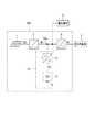
図1は、本発明の一実施形態に係る蓄電池の自己発熱装置を含む、自立型の電源システム100を示す接続図である。この電源システム100は、太陽光発電パネル1と、DC/DCコンバータ2と、双方向性のDC/DCコンバータ3と、蓄電池4と、インバータ5とを備え、これらは、図示のように接続されている。太陽光発電パネル1の出力は、DC/DCコンバータ2により所定の電圧に変換される。また、DC/DCコンバータ2は、MPPT(Maximum Power Point Tracking)制御を行い、太陽光発電パネル1から最大電力を引き出す。DC/DCコンバータ2の出力は、DCバスBdcに接続されている。DCバスBdcからは、直接、直流負荷6に電力を供給することができる。また、DCバスBdcの電圧をインバータ5で交流に変換することにより、交流負荷7に電力を供給することができる。<< Details of Embodiment >>
(First embodiment)
FIG. 1 is a connection diagram showing a self-supporting
DC/DCコンバータ3は、DCバスBdcの電圧を蓄電池4の充電に適した電圧に変換し、蓄電池4を充電する。蓄電池4は、例えば、NaFSA(ナトリウム・ビスフルオロスルフォニルアミド)56mol%と、KFSA(カリウム・ビスフルオロスルフォニルアミド)44mol%との混合物を電解質とする溶融塩電池である。この電解質の融点は57℃である。融点以上の温度では、電解質は溶融し、高濃度のイオンが溶解した電解液となっている。 The DC /
なお、溶融塩としては、上記の他、NaFSAと、LiFSA、KFSA及びCsFSAとの混合物も好適である。また、他の塩を混合する場合もあり(有機カチオン等)、一般には、溶融塩は、(a)NaFSAを含む混合物、(b)NaTFSA(ナトリウム・ビストリフルオロメチルスルフォニルアミド)を含む混合物、(c)NaFTA(ナトリウム・フルオロスルフォニル−トリフルオロメチルスルフォニルアミド)を含む混合物、が適する。 As the molten salt, in addition to the above, a mixture of NaFSA and LiFSA, KFSA and CsFSA is also suitable. In addition, other salts may be mixed (organic cation or the like). Generally, the molten salt includes (a) a mixture containing NaFSA, (b) a mixture containing NaTFSA (sodium bistrifluoromethylsulfonylamide), ( c) Mixtures containing NaFTA (sodium fluorosulfonyl-trifluoromethylsulfonylamide) are suitable.
上記蓄電池4は、融点未満の温度では電解質が固化して、電池として稼働しない状態(充放電不可の状態)となる。従って、蓄電池4は常に、融点以上の温度に維持する必要がある。また、安定した動作のためには、90℃程度の温度に維持することが好ましい。電源システム100の稼働初期の段階では、ヒータ(図示せず。)を用いて蓄電池4を、上記の好適温度(90℃程度)とするが、その後は、ヒータに依存せず、異なる方法によって温度を維持する(詳細後述)。 The
また、例えば太陽光発電パネル1が発電しない夜間には、DC/DCコンバータ3は、蓄電池4の出力電圧を電圧変換してDCバスBdcに提供する。これにより、直流負荷6及び、インバータ5を介して交流負荷7に、それぞれ電力を供給することができる。
蓄電池4には温度センサ8が取り付けられており、温度センサ8の出力(温度検知信号)は、DC/DCコンバータ3に送られる。蓄電池4、温度センサ8及びDC/DCコンバータ3によって、蓄電池の自己発熱装置10が構成されている。For example, at night when the solar
A
次に、蓄電池の自己発熱装置10の動作、及び、これによって蓄電池4の温度を維持する方法について説明する。
図2は、蓄電池4の内部の等価回路を示す図である。蓄電池4は、実際には複数の単位電池の集合体(例えば多数の単位電池を直並列に接続したもの)であるが、ここでは、簡素化して示す。すなわち、蓄電池4は、起電力E[V]である狭義の電池4aと、抵抗値Rの内部抵抗4bとの直列体として表すことができる。充電時には、内部抵抗4bを介して電池4aに電流が流れ込み、放電時は、内部抵抗4bを介して電池4aから電流が流出する。抵抗値R[Ω]の内部抵抗4bに電流I[A]が流れることによる発熱量W[J]は、時間をt[sec]として、
W=R・I2・t
で表される。Next, the operation of the storage battery self-heating
FIG. 2 is a diagram showing an equivalent circuit inside the
W = R · I2 · t
It is represented by
図3は、蓄電池4の温度領域と、放電電流との関係を示す図である。図において、蓄電池4は、例えば57℃〜190℃が稼働温度領域であり、57℃未満及び190℃を超える温度は、使用不可領域である。稼働温度領域は例えば3領域に分けることができ、下から順に、もっと昇温させることが必要な昇温領域、現状の温度を維持すればよい適温領域、そして、温度を下げる方が好ましい降温領域である。 FIG. 3 is a diagram showing the relationship between the temperature region of the
例えば、負荷に対して放電する蓄電池4に求められる電流をI[A](図3の(a)の電流)とする。ここで、単位時間をt[sec]とすると、クーロン量P[C]は、P=I・tである。この電流Iは、連続した値である。ここで、電流を連続値ではなくパルス列にすることを考える。単位時間tを1周期と考えて、その1/2の時間(1/2)tをパルス幅とし、パルスの高さ、すなわち電流値を2Iとする(図3の(b)の電流)。この場合のクーロン量は、P=2I・(1/2)t=I・tであり、(a)の場合とクーロン量は同じである。 For example, the current required for the
さらに、単位時間tの1/4の時間(1/4)tをパルス幅とし、電流値を4Iとする(図3の(c)の電流)。この場合のクーロン量は、P=4I・(1/4)t=I・tであり、(a)の場合とクーロン量は同じである。さらに、一般式としては、パルスの高さ、すなわち電流の大きさを、(a)に示す連続値での電流Iのk倍(k>1)とすると、P=kI・(1/k)t=I・tであり、(a)の場合とクーロン量は同じである。
すなわち、放電電流をパルス列化しても、パルス幅に応じてパルスの高さを変えれば、同じクーロン量を提供することができ、負荷には必要な電力を供給することができる。但し、パルスの高さは、蓄電池4の放電電流の許容上限値Imaxを超えないようにする。Further, a time (1/4) t that is ¼ of the unit time t is set as a pulse width, and a current value is set as 4I (current in FIG. 3C). The coulomb amount in this case is P = 4I · (1/4) t = I · t, and the coulomb amount is the same as in the case of (a). Furthermore, as a general formula, if the height of the pulse, that is, the magnitude of the current is k times the current I at the continuous value shown in (a) (k> 1), P = kI · (1 / k) t = I · t, and the coulomb amount is the same as in the case of (a).
That is, even if the discharge current is converted into a pulse train, if the pulse height is changed according to the pulse width, the same coulomb amount can be provided, and necessary power can be supplied to the load. However, the height of the pulse is set so as not to exceed the allowable upper limit value Imax of the discharge current of the
一方、蓄電池4の内部抵抗4bによる単位時間の発熱量W[J]は、(a)の電流のときは、
W=R・I2t ・・・(1)
である。
これに対して、(b)の電流のときは、
W=R・(2I)2・(t/2)=2R・I2t ・・・(2)
である。
さらに、(c)の電流のときは、
W=R・(4I)2・(t/4)=4R・I2t ・・・(3)
である。
一般式とするには、前述のkを用いて、
W=R・(kI)2・(t/k)=kR・I2t ・・・(4)
である。但し、kI≦Imaxでなければならない。On the other hand, the calorific value W [J] per unit time due to the
W = R · I2 t (1)
It is.
On the other hand, when the current is (b),
W = R · (2I)2 · (t / 2) = 2R · I2 t (2)
It is.
Furthermore, when the current of (c) is
W = R · (4I)2 · (t / 4) = 4R · I2 t (3)
It is.
To obtain a general formula, the above-mentioned k is used,
W = R · (kI)2 · (t / k) = kR · I2 t (4)
It is. However, kI ≦ Imax must be satisfied.
上記の(2)、(3)、(4)式より、クーロン量Pは不変でも、パルス列にすることによって、発熱量を変化させ得ることがわかる。また、パルスの高さとパルス幅とを制御することにより、必要な発熱量を、蓄電池4の内部抵抗4bからの発熱によって得ることができる。
以上が、基本的な考え方であるが、実際には、蓄電池4の電流がパルス列になることにより、蓄電池4の電圧が若干低下する(IRドロップ)。この低下の度合いは、蓄電池によって異なる。そこで、負荷に供給する電力を所望の一定値にするには、余裕をみて、パルス幅を若干長くする必要がある。すなわち、電流をパルス列にすることによる蓄電池4の電圧降下を考慮した余裕時間をα[秒]とし、単位時間tにわたって連続値で電流Iが蓄電池4に流れることを基準として、kを1より大きい数、とすると、パルスの高さIhは、Ih=k・Iであり、パルス幅Δtは、Δt=(t/k)+αである。From the above equations (2), (3), and (4), it can be seen that even if the coulomb amount P is unchanged, the amount of heat generated can be changed by using a pulse train. Further, by controlling the pulse height and the pulse width, a necessary heat generation amount can be obtained by the heat generation from the
The above is the basic idea, but actually, the voltage of the
上記のようなパルス列状の放電電流は、DC/DCコンバータ3が蓄電池4からの出力電流を昇圧チョッパ制御することにより実現される。
また、上記の説明は、放電電流について述べたが、充電電流についても同様である。その場合は、DC/DCコンバータ3がパルス列状の電流を出力することにより、パルス列状の充電電流が実現される。
パルス列の周波数は、例えば数ヘルツ、すなわち1秒間に数パルス程度である。なお、DC/DCコンバータ3には平滑コンデンサ(図示せず。)が内蔵されているが、この程度の低い周波数であれば、パルス列の波形が平滑によって鈍ることは、ほとんどない。The discharge current in the form of a pulse train as described above is realized by the DC /
Moreover, although the above description has been described with respect to the discharge current, the same applies to the charging current. In that case, the DC /
The frequency of the pulse train is, for example, several hertz, that is, about several pulses per second. Although a smoothing capacitor (not shown) is built in the DC /
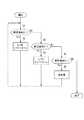
図4は、DC/DCコンバータ3によって実行される、蓄電池4の放電電流/充電電流の制御の一例を示すフローチャートである。このフローチャートの処理が開始されるときは、蓄電池4は既に稼働状態にある。まず、ステップS1において、DC/DCコンバータ3は、温度検知信号に基づいて、蓄電池4が昇温領域にあるか否かを判定する。昇温領域にある場合、すなわち蓄電池4の発熱量を特に増大させる必要があると判定した場合は、DC/DCコンバータ3は、電流をパルス列とするとともに、例えば、パルスの高さIhをIh=4I、パルス幅Δtを、Δt=(t/4)+αとする(ステップS2)。FIG. 4 is a flowchart showing an example of control of the discharge current / charge current of the
なお、Ihが許容上限値Imaxを超える場合には、Ih=Imaxに制限し、パルス幅もそれに応じた値としなければならない。許容上限値Imaxは、蓄電池の種類、電池容量、温度等で変化する。DC/DCコンバータ3は、蓄電池4の温度を把握しており、また、蓄電池4と直結しているので、OCV(Open Circuit Voltage)から電池容量を推定することもできる。従って、DC/DCコンバータ3は許容上限値Imaxを、動的に把握することができる。また、予め、許容上限値Imaxを、固定値として設定することも可能である。When Ih exceeds the allowable upper limit value Imax , it is necessary to limit to Ih = Imax and set the pulse width to a value corresponding thereto. The allowable upper limit value Imax varies depending on the type of storage battery, battery capacity, temperature, and the like. Since the DC /
また、ステップS1で昇温領域でない場合、DC/DCコンバータ3は、ステップS3において、蓄電池4が適温領域にあるか否かを判定する。適温領域にある場合、すなわち蓄電池4の発熱量を増大させる必要があると判定した場合、DC/DCコンバータ3は、電流をパルス列とするとともに、例えば、パルスの高さIhをIh=2I、パルス幅Δtを、Δt=(t/2)+αとする(ステップS4)。Further, when the temperature is not in the temperature rising range in step S1, the DC /
また、ステップS3で適温領域でない場合、DC/DCコンバータ3は、ステップS5において、蓄電池4が降温領域にあるか否かを判定する。降温領域にある場合、DC/DCコンバータ3は、電流を連続値とする(ステップS6)。
なお、ステップS5において降温領域でない場合は、昇温領域、適温領域、降温領域のいずれでもない使用不可領域であることになるので、処理は終了する。When the temperature is not in the proper temperature range in step S3, the DC /
In step S5, if it is not the temperature-decreasing region, it is an unusable region that is not one of the temperature-raising region, the appropriate temperature region, and the temperature-decreasing region, and the process ends.
以上、詳述したように、蓄電池の自己発熱装置10において、DC/DCコンバータ3は、昇温又は保温目的で蓄電池4の発熱量を増大させる必要があると判定した場合は、蓄電池4から出力される放電電流(又は蓄電池4に入力される充電電流)をパルス列にする。このパルス列におけるパルスの高さとパルス幅とを制御することにより、必要な発熱量を、蓄電池4の内部抵抗4bからの発熱によって得ることができる。パルスの高さとパルス幅とを制御することにより、連続した電流と比べて、同じクーロン量でも発熱量を変化させることが可能となる。そして、必要な発熱量が大きいほど、パルスを高く、かつ、パルス幅を狭くする。逆に言えば、必要な発熱量が小さいほど、パルスを低く、かつ、パルス幅を広くする。 As described above in detail, in the self-heating
このような熱は、蓄電池4の電池容器の内部から発生するため、効率よく蓄電池4を昇温させ、又は保温することができる。また、蓄電池4が、単位電池を集合させて成る組電池の場合に、ヒータ等の外部加熱装置を用いると加熱のむらが生じやすく、また、熱の一部が外へ逃げることによる無駄が生じる。そのため、熱がなるべく外へ逃げず、かつ、内部で均一になるようにするための十分な断熱構造を持つ外箱が必要であるが、上記のような内部抵抗による発熱の場合は、電池容器の中から加熱するため、外箱の断熱構造を簡素化することができる。
また、このような自己発熱装置10を含む電源システム100は、効率よく蓄電池4を昇温させ、又は保温することができる。Since such heat is generated from the inside of the battery container of the
Moreover, the
また、蓄電池4の劣化と、内部抵抗4bの抵抗値とは関連性があり、劣化が進むと抵抗値が大きくなる。従って、パルス列の定電流を流した場合の蓄電池4の温度上昇の速度から、閾値との比較により、劣化診断を行うことができる。 Further, the deterioration of the
(第2実施形態)
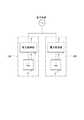
図5は、他の実施形態に係る蓄電池の自己発熱装置を示す接続図である。図において、例えば1つの電力系統の下に、2組の電力変換器9と蓄電池4とが設けられている。電力変換器9は双方向性であり、蓄電池4を充電するときは整流器となり、蓄電池4から放電させるときはインバータとなる。蓄電池4には温度センサ8が設けられている。左側の蓄電池4、温度センサ8及び電力変換器9は、蓄電池の自己発熱装置10Aを構成している。同様に、右側の蓄電池4、温度センサ8及び電力変換器9は、蓄電池の自己発熱装置10Bを構成している。(Second Embodiment)
FIG. 5 is a connection diagram illustrating a self-heating device for a storage battery according to another embodiment. In the figure, for example, two
図5のような構成では、一方の組の蓄電池4の放電により、他方の組の蓄電池4を充電することができる。従って、エネルギーを負荷に供給する場合でなくても、また、電力系統から充電エネルギーをもらわなくても、蓄電池4の組間で放電・充電によりエネルギーのやりとりをして、蓄電池4を積極的に発熱させることができる。
この場合、電力変換器9を2つ通すことによる若干の電力損失はあるが、負荷や他の電源に依存しなくとも、蓄電池4の相互間で昇温又は保温をすることができるという利点がある。
また、図5は、2組の例であるが3組以上で相互にエネルギーのやりとりをして蓄電池を自己発熱させることも可能である。In the configuration as shown in FIG. 5, the other set of
In this case, although there is a slight power loss due to passing two
Moreover, although FIG. 5 is an example of 2 sets, it is also possible to self-heat a storage battery by exchanging energy mutually in 3 or more sets.
(その他)
なお、図1では、自立型の電源システム100を例示した。これは、発電電力が限られる点で、蓄電池の自己加熱装置10を適用することが好適な一例である。但し、商用電源を併用する電源システムであっても、上記のような蓄電池の自己加熱装置10を適用することで、より省電力を実現することができる。(Other)
In FIG. 1, a self-supporting
なお、上記の各実施形態は、蓄電池4として溶融塩電池を挙げたが、リチウムイオン電池でも寒冷地で使用する場合には、性能を十分に発揮させるために、加熱が必要な場合があり、このような場合にも、上述の蓄電池の自己発熱装置を適用することができる。
また、溶融塩電池よりもさらに高温で使用されるNaS(ナトリウム硫黄)電池でも、上述の蓄電池の自己発熱装置を適用することができる。In addition, although each said embodiment mentioned the molten salt battery as the
The above-described self-heating device for a storage battery can also be applied to a NaS (sodium sulfur) battery that is used at a higher temperature than a molten salt battery.
なお、今回開示された実施の形態はすべての点で例示であって制限的なものではないと考えられるべきである。本発明の範囲は特許請求の範囲によって示され、特許請求の範囲と均等の意味及び範囲内での全ての変更が含まれることが意図される。 The embodiment disclosed this time should be considered as illustrative in all points and not restrictive. The scope of the present invention is defined by the terms of the claims, and is intended to include any modifications within the scope and meaning equivalent to the terms of the claims.
1 太陽光発電パネル
2 DC/DCコンバータ
3 DC/DCコンバータ
4 蓄電池
4a 電池
4b 内部抵抗
5 インバータ
6 直流負荷
7 交流負荷
8 温度センサ
9 電力変換器
10,10A,10B 蓄電池の自己発熱装置
100 電源システムDESCRIPTION OF
Claims (8)
Translated fromJapanese前記蓄電池の温度を検知する温度センサと、
前記蓄電池に接続され、前記蓄電池の放電に関わる電力変換器と、を備え、
前記電力変換器は、前記温度センサの検知出力に基づいて、前記蓄電池の発熱量を増大させる必要があると判定した場合は、前記蓄電池から出力される放電電流をパルス列にするとともに、必要な発熱量が大きいほど、前記蓄電池の許容上限値までの範囲内でパルスを高く、かつ、パルス幅を狭くする、蓄電池の自己発熱装置。A rechargeable storage battery;
A temperature sensor for detecting the temperature of the storage battery;
A power converter connected to the storage battery and involved in discharging the storage battery,
If the power converter determines that it is necessary to increase the heat generation amount of the storage battery based on the detection output of the temperature sensor, the discharge current output from the storage battery is converted into a pulse train and the necessary heat generation A self-heating device for a storage battery in which the larger the amount, the higher the pulse and the narrower the pulse width within a range up to the allowable upper limit of the storage battery.
前記蓄電池に接続され、前記蓄電池の放電に関わる電力変換器は、前記温度センサの検知出力に基づいて、前記蓄電池の発熱量を増大させる必要があると判定した場合は、前記蓄電池の放電電流をパルス列にするとともに、必要な発熱量が大きいほど、前記蓄電池の許容上限値までの範囲内でパルスを高く、かつ、パルス幅を狭くする、蓄電池の自己発熱方法。The temperature of the rechargeable storage battery is detected by a temperature sensor,
If the power converter connected to the storage battery and involved in the discharge of the storage battery determines that the amount of heat generated by the storage battery needs to be increased based on the detection output of the temperature sensor, the discharge current of the storage battery is A self-heating method for a storage battery in which a pulse train is increased and a pulse is increased and a pulse width is narrowed within a range up to the allowable upper limit value of the storage battery as the required heat generation amount is larger.
Priority Applications (1)
| Application Number | Priority Date | Filing Date | Title |
|---|---|---|---|
| JP2013167399AJP6160355B2 (en) | 2013-08-12 | 2013-08-12 | Storage battery self-heating device, storage battery self-heating method and power supply system |
Applications Claiming Priority (1)
| Application Number | Priority Date | Filing Date | Title |
|---|---|---|---|
| JP2013167399AJP6160355B2 (en) | 2013-08-12 | 2013-08-12 | Storage battery self-heating device, storage battery self-heating method and power supply system |
Publications (2)
| Publication Number | Publication Date |
|---|---|
| JP2015037013Atrue JP2015037013A (en) | 2015-02-23 |
| JP6160355B2 JP6160355B2 (en) | 2017-07-12 |
Family
ID=52687419
Family Applications (1)
| Application Number | Title | Priority Date | Filing Date |
|---|---|---|---|
| JP2013167399AActiveJP6160355B2 (en) | 2013-08-12 | 2013-08-12 | Storage battery self-heating device, storage battery self-heating method and power supply system |
Country Status (1)
| Country | Link |
|---|---|
| JP (1) | JP6160355B2 (en) |
Cited By (8)
| Publication number | Priority date | Publication date | Assignee | Title |
|---|---|---|---|---|
| JP2017127173A (en)* | 2016-01-14 | 2017-07-20 | 凌和電子株式会社 | Power storage device |
| JP2019009002A (en)* | 2017-06-26 | 2019-01-17 | アクソンデータマシン株式会社 | Power supply device comprising lithium ion secondary battery, and method of controlling the same |
| CN110137628A (en)* | 2019-05-06 | 2019-08-16 | 奇瑞商用车(安徽)有限公司 | A kind of power battery self-heating system and its heating means |
| KR102064876B1 (en)* | 2019-07-26 | 2020-02-12 | (주)비엠일렉텍 | Multi type charger capable of extending battery life time by temperature control |
| US11453294B2 (en) | 2019-03-25 | 2022-09-27 | Marelli Corporation | Control device of motor driven vehicle, control method of motor driven vehicle and non-transitory computer readable storage medium storing control program of motor driven vehicle |
| US11462933B2 (en) | 2017-11-16 | 2022-10-04 | Murata Manufacturing Co., Ltd. | Power storage module and power supply system |
| CN115621621A (en)* | 2022-12-19 | 2023-01-17 | 中国人民解放军国防科技大学 | A rapid internal heating method for lithium batteries based on pulse excitation |
| JP2024525756A (en)* | 2021-10-29 | 2024-07-12 | 寧徳時代新能源科技股▲分▼有限公司 | Power battery heating method and heating system |
Citations (7)
| Publication number | Priority date | Publication date | Assignee | Title |
|---|---|---|---|---|
| JPH0817474A (en)* | 1994-07-01 | 1996-01-19 | Hitachi Ltd | NaS battery temperature controller |
| JP2005332777A (en)* | 2004-05-21 | 2005-12-02 | Fuji Heavy Ind Ltd | Warm-up control unit of battery |
| JP2008148408A (en)* | 2006-12-07 | 2008-06-26 | West Japan Railway Co | Heat insulation control method of accumulation device in power storage system, and power storage system |
| JP2008301638A (en)* | 2007-05-31 | 2008-12-11 | Sanyo Electric Co Ltd | Battery charging circuit |
| WO2012060016A1 (en)* | 2010-11-05 | 2012-05-10 | 三菱電機株式会社 | Charging/discharging device and method for controlling charging and discharging |
| JP2012152057A (en)* | 2011-01-20 | 2012-08-09 | Toshiba Mitsubishi-Electric Industrial System Corp | Power supply apparatus |
| WO2013027638A1 (en)* | 2011-08-19 | 2013-02-28 | Ngk Insulators, Ltd. | Method of controlling storage battery, apparatus for controlling storage battery, and electric power control system |
- 2013
- 2013-08-12JPJP2013167399Apatent/JP6160355B2/enactiveActive
Patent Citations (7)
| Publication number | Priority date | Publication date | Assignee | Title |
|---|---|---|---|---|
| JPH0817474A (en)* | 1994-07-01 | 1996-01-19 | Hitachi Ltd | NaS battery temperature controller |
| JP2005332777A (en)* | 2004-05-21 | 2005-12-02 | Fuji Heavy Ind Ltd | Warm-up control unit of battery |
| JP2008148408A (en)* | 2006-12-07 | 2008-06-26 | West Japan Railway Co | Heat insulation control method of accumulation device in power storage system, and power storage system |
| JP2008301638A (en)* | 2007-05-31 | 2008-12-11 | Sanyo Electric Co Ltd | Battery charging circuit |
| WO2012060016A1 (en)* | 2010-11-05 | 2012-05-10 | 三菱電機株式会社 | Charging/discharging device and method for controlling charging and discharging |
| JP2012152057A (en)* | 2011-01-20 | 2012-08-09 | Toshiba Mitsubishi-Electric Industrial System Corp | Power supply apparatus |
| WO2013027638A1 (en)* | 2011-08-19 | 2013-02-28 | Ngk Insulators, Ltd. | Method of controlling storage battery, apparatus for controlling storage battery, and electric power control system |
Cited By (10)
| Publication number | Priority date | Publication date | Assignee | Title |
|---|---|---|---|---|
| JP2017127173A (en)* | 2016-01-14 | 2017-07-20 | 凌和電子株式会社 | Power storage device |
| JP2019009002A (en)* | 2017-06-26 | 2019-01-17 | アクソンデータマシン株式会社 | Power supply device comprising lithium ion secondary battery, and method of controlling the same |
| US11462933B2 (en) | 2017-11-16 | 2022-10-04 | Murata Manufacturing Co., Ltd. | Power storage module and power supply system |
| US11453294B2 (en) | 2019-03-25 | 2022-09-27 | Marelli Corporation | Control device of motor driven vehicle, control method of motor driven vehicle and non-transitory computer readable storage medium storing control program of motor driven vehicle |
| CN110137628A (en)* | 2019-05-06 | 2019-08-16 | 奇瑞商用车(安徽)有限公司 | A kind of power battery self-heating system and its heating means |
| KR102064876B1 (en)* | 2019-07-26 | 2020-02-12 | (주)비엠일렉텍 | Multi type charger capable of extending battery life time by temperature control |
| JP2024525756A (en)* | 2021-10-29 | 2024-07-12 | 寧徳時代新能源科技股▲分▼有限公司 | Power battery heating method and heating system |
| JP7684511B2 (en) | 2021-10-29 | 2025-05-27 | 香港時代新能源科技有限公司 | Power battery heating method and heating system |
| US12431556B2 (en) | 2021-10-29 | 2025-09-30 | Contemporary Amperex Technology (Hong Kong) Limited | Heating method and heating system of traction battery |
| CN115621621A (en)* | 2022-12-19 | 2023-01-17 | 中国人民解放军国防科技大学 | A rapid internal heating method for lithium batteries based on pulse excitation |
Also Published As
| Publication number | Publication date |
|---|---|
| JP6160355B2 (en) | 2017-07-12 |
Similar Documents
| Publication | Publication Date | Title |
|---|---|---|
| JP6160355B2 (en) | Storage battery self-heating device, storage battery self-heating method and power supply system | |
| JP6951409B2 (en) | Rechargeable battery heating method, control unit and heating circuit | |
| CN108012538B (en) | hybrid energy storage | |
| US10355509B2 (en) | Management apparatus, charge and discharge control apparatus, power storage system, and charge and discharge control method | |
| JP5819443B2 (en) | Battery control device, battery system | |
| JP5996151B1 (en) | Battery system | |
| CN103190056B (en) | Charging control method and discharging control method for electricity storage device | |
| JPWO2012169062A1 (en) | Battery control device, battery system | |
| JP5887431B2 (en) | Battery complex system | |
| WO2013051135A1 (en) | Battery controller | |
| CN102598468A (en) | Power control device, power control method, and power supply system | |
| CN112186305B (en) | Low-temperature battery hybrid self-heating device and self-heating method based on same | |
| US20090153102A1 (en) | Method and System For Load Shifting | |
| KR101688485B1 (en) | Energy storage apparatus | |
| US20140286071A1 (en) | Power conversion device having battery heating function | |
| JP5461602B2 (en) | Power management system | |
| JP2019110712A (en) | Power storage system | |
| JP5709824B2 (en) | Battery system, charge control device and charge control method | |
| Zhong et al. | A safety-reinforced mutual pulse heating strategy based on microscopic-state estimation for power-redistributable lithium-ion battery pack | |
| AU2023243021A1 (en) | Systems, devices, and methods for pulse charging and pulse heating of rechargeable energy sources | |
| Bisht et al. | Performance Analysis of Optimized Active Cell Balancing Circuits in Lithium‐Ion Battery Pack | |
| JP6489332B2 (en) | Storage battery unit and power storage system | |
| JP7672579B2 (en) | Storage battery temperature rise control device and storage battery temperature rise system | |
| Pathak | Model Based Battery Management Systems-From Theory to Practice | |
| JP2013254646A (en) | Battery system |
Legal Events
| Date | Code | Title | Description |
|---|---|---|---|
| A621 | Written request for application examination | Free format text:JAPANESE INTERMEDIATE CODE: A621 Effective date:20160323 | |
| A977 | Report on retrieval | Free format text:JAPANESE INTERMEDIATE CODE: A971007 Effective date:20170125 | |
| A131 | Notification of reasons for refusal | Free format text:JAPANESE INTERMEDIATE CODE: A131 Effective date:20170131 | |
| A521 | Request for written amendment filed | Free format text:JAPANESE INTERMEDIATE CODE: A523 Effective date:20170313 | |
| A131 | Notification of reasons for refusal | Free format text:JAPANESE INTERMEDIATE CODE: A131 Effective date:20170404 | |
| A521 | Request for written amendment filed | Free format text:JAPANESE INTERMEDIATE CODE: A523 Effective date:20170427 | |
| TRDD | Decision of grant or rejection written | ||
| A01 | Written decision to grant a patent or to grant a registration (utility model) | Free format text:JAPANESE INTERMEDIATE CODE: A01 Effective date:20170516 | |
| A61 | First payment of annual fees (during grant procedure) | Free format text:JAPANESE INTERMEDIATE CODE: A61 Effective date:20170529 | |
| R150 | Certificate of patent or registration of utility model | Ref document number:6160355 Country of ref document:JP Free format text:JAPANESE INTERMEDIATE CODE: R150 | |
| R250 | Receipt of annual fees | Free format text:JAPANESE INTERMEDIATE CODE: R250 | |
| R250 | Receipt of annual fees | Free format text:JAPANESE INTERMEDIATE CODE: R250 | |
| R250 | Receipt of annual fees | Free format text:JAPANESE INTERMEDIATE CODE: R250 | |
| R250 | Receipt of annual fees | Free format text:JAPANESE INTERMEDIATE CODE: R250 | |
| R250 | Receipt of annual fees | Free format text:JAPANESE INTERMEDIATE CODE: R250 | |
| R250 | Receipt of annual fees | Free format text:JAPANESE INTERMEDIATE CODE: R250 |