JP2015024784A - Structure of instrument panel - Google Patents
Structure of instrument panelDownload PDFInfo
- Publication number
- JP2015024784A JP2015024784AJP2013156714AJP2013156714AJP2015024784AJP 2015024784 AJP2015024784 AJP 2015024784AJP 2013156714 AJP2013156714 AJP 2013156714AJP 2013156714 AJP2013156714 AJP 2013156714AJP 2015024784 AJP2015024784 AJP 2015024784A
- Authority
- JP
- Japan
- Prior art keywords
- instrument panel
- vehicle
- tip
- inclined surface
- cover
- Prior art date
- Legal status (The legal status is an assumption and is not a legal conclusion. Google has not performed a legal analysis and makes no representation as to the accuracy of the status listed.)
- Pending
Links
- 239000005357flat glassSubstances0.000claimsabstractdescription29
- 230000002093peripheral effectEffects0.000claimsdescription9
- 238000010276constructionMethods0.000claims1
- 238000010521absorption reactionMethods0.000abstractdescription7
- 230000007246mechanismEffects0.000abstractdescription6
- 239000011521glassSubstances0.000abstractdescription4
- 238000003780insertionMethods0.000description3
- 230000037431insertionEffects0.000description3
- 230000000694effectsEffects0.000description2
- 238000009434installationMethods0.000description2
- 230000009466transformationEffects0.000description2
- 230000015572biosynthetic processEffects0.000description1
- 239000012141concentrateSubstances0.000description1
- 238000007796conventional methodMethods0.000description1
- 238000013461designMethods0.000description1
- 238000000034methodMethods0.000description1
- 238000012986modificationMethods0.000description1
- 230000004048modificationEffects0.000description1
- 238000003466weldingMethods0.000description1
Images


Classifications
- B—PERFORMING OPERATIONS; TRANSPORTING
- B60—VEHICLES IN GENERAL
- B60R—VEHICLES, VEHICLE FITTINGS, OR VEHICLE PARTS, NOT OTHERWISE PROVIDED FOR
- B60R21/00—Arrangements or fittings on vehicles for protecting or preventing injuries to occupants or pedestrians in case of accidents or other traffic risks
- B60R21/34—Protecting non-occupants of a vehicle, e.g. pedestrians
- B60R2021/343—Protecting non-occupants of a vehicle, e.g. pedestrians using deformable body panel, bodywork or components
Landscapes
- Engineering & Computer Science (AREA)
- Mechanical Engineering (AREA)
- Body Structure For Vehicles (AREA)
- Instrument Panels (AREA)
Abstract
Description
Translated fromJapanese本発明は、車両の車室内の前部に設けられるインストルメントパネルの構造に関する。 The present invention relates to a structure of an instrument panel provided at a front portion of a vehicle interior of a vehicle.
通常、車両走行中に歩行者(もしくは衝突物)が車体前部に衝突した時に、当該歩行者への衝突エネルギーを軽減させるためには、車室内の前部に設けられるインストルメントパネルの内部(特に先端部)の構造が重要となっている。その理由としては、歩行者が車体前部のフロントウインドガラスに当接する際に、車室内のインストルメントパネルなどの構造物が支持してしまうと、歩行者に大きな衝突エネルギーが負荷されてしまう可能性を有しているからである。 Usually, when a pedestrian (or colliding object) collides with the front part of the vehicle body while the vehicle is running, in order to reduce the collision energy to the pedestrian, the inside of the instrument panel provided in the front part of the vehicle interior ( In particular, the structure of the tip portion is important. The reason for this is that when a pedestrian comes into contact with the front window glass at the front of the vehicle body, if a structure such as an instrument panel in the passenger compartment is supported, the pedestrian may be loaded with a large collision energy. It is because it has sex.
そこで、従来技術の中には、衝突エネルギーを吸収するような機構がインストルメントパネルとは別個に設けられているものがあり、当該機構によって歩行者に負荷される衝突エネルギーを軽減させることが行われている(例えば、特許文献1、2参照)。 Therefore, some conventional techniques have a mechanism that absorbs collision energy separately from the instrument panel, and the mechanism can reduce the collision energy applied to pedestrians. (For example, see
しかしながら、上述した従来の構造では、衝突エネルギーを吸収するための機構をインストルメントパネルと別個に設けているので、部品点数及び組付工数が増え、コスト高を招くのみならず、そのような機構をレイアウトする設置スペースが必要になるという問題を有している。特に、近年は搭載仕様が拡大しており、これに伴って、インストルメントパネルの内部への搭載機器の収納スペースも拡大しており、そのような機構のレイアウトスペースを別途設けることが難しくなってきている。 However, since the mechanism for absorbing the collision energy is provided separately from the instrument panel in the conventional structure described above, not only the number of parts and the number of assembling steps are increased, but the cost is increased. There is a problem that an installation space for laying out the space is required. In particular, in recent years, the mounting specifications have expanded, and along with this, the storage space for mounted devices inside the instrument panel has also expanded, making it difficult to provide a separate layout space for such mechanisms. ing.
本発明はこのような実状に鑑みてなされたものであって、その目的は、エネルギー吸収機構を別個に設けることなく、インストルメントパネルの先端部側の上面に脆弱部を設けることによって、フロントウインドガラスからの衝突エネルギーを効果的に吸収することが可能なインストルメントパネルの構造を提供することにある。 The present invention has been made in view of such a situation, and an object of the present invention is to provide a front window by providing a weak portion on the top surface of the instrument panel without providing an energy absorbing mechanism separately. An object of the present invention is to provide an instrument panel structure capable of effectively absorbing collision energy from glass.
上記従来技術の有する課題を解決するために、本発明は、フロントウインドガラスの下方に位置するインストルメントパネルの先端部側の上面に、前記フロントウインドガラスに対して交差する方向へ延びる傾斜面が設けられ、前記インストルメントパネルの先端部側の上面と前記傾斜面との境界線に、脆弱部が設けられている。 In order to solve the above-described problems of the prior art, the present invention provides an inclined surface extending in a direction intersecting with the front window glass on the upper surface of the instrument panel located below the front window glass. The weak part is provided in the boundary line of the upper surface by the side of the front-end | tip part of the said instrument panel, and the said inclined surface.
また、本発明において、車体側には、車両後方へ向かって突出する片持ち支持構造の固定部が設けられ、前記傾斜面よりも車両前方側の前記インストルメントパネルの先端部を前記固定部に係止させることによって、前記インストルメントパネルの先端部が前記車体に固定されている。 Further, in the present invention, a fixed portion of a cantilever support structure that protrudes toward the rear of the vehicle is provided on the vehicle body side, and a tip portion of the instrument panel on the vehicle front side with respect to the inclined surface is used as the fixed portion. By locking, the tip of the instrument panel is fixed to the vehicle body.
さらに、本発明において、前記インストルメントパネルの先端部と前記固定部との上下間には、車両下方へ向かって変形する前記インストルメントパネルの先端部が前記固定部と接触しないようにするための隙間が設けられている。 Furthermore, in this invention, it is for preventing the front-end | tip part of the said instrument panel which deform | transforms toward the vehicle downward direction between the front-end | tip part of the said instrument panel and the said fixed part from contacting the said fixed part. A gap is provided.
そして、本発明において、前記脆弱部は、前記インストルメントパネルの先端部側の上面の板厚を薄肉にすることによって形成されている。 And in this invention, the said weak part is formed by making thin the plate | board thickness of the upper surface at the side of the front-end | tip part of the said instrument panel.
また、本発明において、前記脆弱部は、前記インストルメントパネルの先端部側の裏面に切欠きを設けることによって形成されている。 Moreover, in this invention, the said weak part is formed by providing a notch in the back surface at the side of the front-end | tip part of the said instrument panel.
さらに、本発明において、前記脆弱部は、前記インストルメントパネルの先端部の車両幅方向に沿って延在している。 Furthermore, in this invention, the said weak part is extended along the vehicle width direction of the front-end | tip part of the said instrument panel.
そして、本発明において、前記傾斜面は、前記インストルメントパネルの先端部側の上面の車両高さ方向における頂点部から設けられ、前記脆弱部は、前記頂点部に設けられている。 And in this invention, the said inclined surface is provided from the vertex part in the vehicle height direction of the upper surface at the side of the front-end | tip part of the said instrument panel, and the said weak part is provided in the said vertex part.
また、本発明において、前記傾斜面と前記固定部との間に位置する前記インストルメントパネルの先端部側の上面には、別体のカバーによって覆われる開口部が設けられ、前記カバーの車両前方側には引っ掛け部が設けられているとともに、前記カバーの車両後方側には係止部が設けられ、前記引っ掛け部及び前記係止部を前記開口部の周縁部に係合させることによって、前記カバーが前記インストルメントパネルの先端部側の上面に取付けられている。 In the present invention, an opening covered with a separate cover is provided on the top surface of the instrument panel positioned between the inclined surface and the fixed portion, and the vehicle front side of the cover. A hook portion is provided on the side, and a latch portion is provided on the vehicle rear side of the cover, and by engaging the hook portion and the latch portion with a peripheral edge portion of the opening, A cover is attached to the upper surface of the instrument panel on the tip side.
さらに、本発明において、前記引っ掛け部は、断面L字状に形成され、前記引っ掛け部の先端側は、前記フロントウインドガラスの面と略平行に配置されている。 Furthermore, in the present invention, the hook portion is formed in an L-shaped cross section, and the tip end side of the hook portion is disposed substantially parallel to the surface of the front window glass.
上述の如く、本発明に係るインストルメントパネルの構造は、フロントウインドガラスの下方に位置するインストルメントパネルの先端部側の上面に、前記フロントウインドガラスに対して交差する方向へ延びる傾斜面が設けられ、前記インストルメントパネルの先端部側の上面と前記傾斜面との境界線に、脆弱部が設けられているので、衝突時にフロントウインドガラスからの衝突エネルギーに対して傾斜面が支持面となり、脆弱部を起点としてインストルメントパネルの先端部が車両下方へ移動するたわみ変形を起こすことになり、これによって、当該衝突エネルギーを吸収することができ、歩行者保護性能の向上を図ることができる。 As described above, the structure of the instrument panel according to the present invention is provided with an inclined surface extending in a direction intersecting with the front window glass on the upper surface of the instrument panel located below the front window glass. Since the fragile portion is provided at the boundary line between the upper surface on the tip side of the instrument panel and the inclined surface, the inclined surface becomes a support surface against the collision energy from the front window glass at the time of collision, The leading edge of the instrument panel starts to bend and deforms starting from the fragile portion, whereby the collision energy can be absorbed and pedestrian protection performance can be improved.
また、本発明において、車体側には、車両後方へ向かって突出する片持ち支持構造の固定部が設けられ、前記傾斜面よりも車両前方側の前記インストルメントパネルの先端部を前記固定部に係止させることによって、前記インストルメントパネルの先端部が前記車体に固定されているので、衝突時にフロントウインドガラスを介してインストルメントパネルの先端部が受ける衝突エネルギーに対して、インストルメントパネルの先端部が車両下方へ移動する際に、車体側の固定部も連動して下方移動を起こして変形しやすくなり、インストルメントパネルの先端部の変形を補助できるとともに、インストルメントパネルが衝突エネルギーを受け流すように変形することで、当該衝突エネルギーの吸収性能をより一層高めることができる。しかも、固定部から脆弱部までを衝突エネルギーの吸収領域とし、他の部分を剛性保持領域とすることが可能となり、明確な変形形態を採用することができる。 Further, in the present invention, a fixed portion of a cantilever support structure that protrudes toward the rear of the vehicle is provided on the vehicle body side, and a tip portion of the instrument panel on the vehicle front side with respect to the inclined surface is used as the fixed portion. By locking, the tip of the instrument panel is fixed to the vehicle body, so that the tip of the instrument panel against the collision energy received by the tip of the instrument panel via the front window glass during a collision. When the part moves downward in the vehicle, the fixed part on the vehicle body also moves downward and becomes easy to deform, assisting the deformation of the tip of the instrument panel, and the instrument panel receives collision energy By deforming as described above, the absorption performance of the collision energy can be further enhanced. Moreover, it is possible to use the collision energy absorption region from the fixed portion to the fragile portion and the other portion as the rigidity holding region, and a clear deformation mode can be adopted.
さらに、本発明において、前記インストルメントパネルの先端部と前記固定部との上下間には、車両下方へ向かって変形する前記インストルメントパネルの先端部が前記固定部と接触しないようにするための隙間が設けられているので、フロントウインドガラスからの衝突エネルギーによってインストルメントパネルの先端部が車両下方へ移動する際に、固定部がインストルメントパネルの先端部の変形を妨げることは無くなり、インストルメントパネルの先端部が最大限に変形でき、当該衝突エネルギーの吸収効果を促進させることができる。 Furthermore, in this invention, it is for preventing the front-end | tip part of the said instrument panel which deform | transforms toward the vehicle downward direction between the front-end | tip part of the said instrument panel and the said fixed part from contacting the said fixed part. Since there is a gap, when the front end of the instrument panel moves down the vehicle due to collision energy from the front windshield, the fixed part does not hinder the deformation of the front end of the instrument panel. The front-end | tip part of a panel can deform | transform to the maximum and can promote the absorption effect of the said collision energy.
そして、本発明において、前記脆弱部は、前記インストルメントパネルの先端部側の上面の板厚を薄肉にすることによって形成されているので、車室内の乗員に近い車両後方側のインストルメントパネルの上面を乗員が触れても、ベカツキなどを起こすことがない安定した剛性及び外観品質を保つことができる。 And in this invention, since the said weak part is formed by making thin the plate | board thickness of the upper surface by the side of the front-end | tip part of the said instrument panel, the instrument panel of the vehicle rear side close | similar to the passenger | crew of a vehicle interior Even if the occupant touches the upper surface, it is possible to maintain stable rigidity and appearance quality that do not cause any stickiness.
また、本発明において、前記脆弱部は、前記インストルメントパネルの先端部側の裏面に切欠きを設けることによって形成されているので、インストルメントパネルの成形性を損なうことなく、脆弱部を形成することができる。しかも、通常走行時は、車体から車両後方側へ伝達される振動を切欠きによって遮断することができ、車室内の居住性向上を図ることができる。 Further, in the present invention, the fragile portion is formed by providing a notch on the back surface on the distal end side of the instrument panel, and thus forms the fragile portion without impairing the moldability of the instrument panel. be able to. In addition, during normal driving, vibration transmitted from the vehicle body to the vehicle rear side can be cut off by the notch, and the comfort in the vehicle compartment can be improved.
さらに、本発明において、前記脆弱部は、前記インストルメントパネルの先端部の車両幅方向に沿って延在しているので、車両幅方向で見た場合、フロントウインドガラスからの衝突荷重が集中する部分をインストルメントパネルの先端部に作り出すということは起こらず、インストルメントパネルの先端部の意図しない変形の発生を抑制することができる。 Furthermore, in the present invention, since the weakened portion extends along the vehicle width direction of the tip portion of the instrument panel, when viewed in the vehicle width direction, the collision load from the front window glass is concentrated. It does not occur that the portion is created at the tip of the instrument panel, and unintended deformation of the tip of the instrument panel can be suppressed.
そして、本発明において、前記傾斜面は、前記インストルメントパネルの先端部側の上面の車両高さ方向における頂点部から設けられ、前記脆弱部は、前記頂点部に設けられているので、フロントウインドガラスからの衝突エネルギーによってインストルメントパネルの先端部が折れやすくなり、当該衝突エネルギーをより効果的に吸収することができる。 In the present invention, the inclined surface is provided from the apex portion in the vehicle height direction of the upper surface on the tip end side of the instrument panel, and the fragile portion is provided at the apex portion. The tip of the instrument panel is easily broken by the collision energy from the glass, and the collision energy can be absorbed more effectively.
また、本発明において、前記傾斜面と前記固定部との間に位置する前記インストルメントパネルの先端部側の上面には、別体のカバーによって覆われる開口部が設けられ、前記カバーの車両前方側には引っ掛け部が設けられているとともに、前記カバーの車両後方側には係止部が設けられ、前記引っ掛け部及び前記係止部を前記開口部の周縁部に係合させることによって、前記カバーが前記インストルメントパネルの先端部側の上面に取付けられているので、フロントウインドガラスからの衝突エネルギーによってインストルメントパネルの先端部が車両下方へ移動する際に、カバーの車両前方側は下方移動に追従する一方、過荷重時にはカバーの車両後方側が外れることでインストルメントパネルの先端部の下方移動を邪魔するということはなく、当該衝突エネルギーの吸収効果を助長することができる。しかも、カバーが外れた後は、インストルメントパネルの先端部側の上面に開口部が露出することになるので、インストルメントパネルの先端部の下方移動を助長でき、当該衝突エネルギーの吸収性能を高めることができる。 In the present invention, an opening covered with a separate cover is provided on the top surface of the instrument panel positioned between the inclined surface and the fixed portion, and the vehicle front side of the cover. A hook portion is provided on the side, and a latch portion is provided on the vehicle rear side of the cover, and by engaging the hook portion and the latch portion with a peripheral edge portion of the opening, Since the cover is attached to the upper surface of the instrument panel at the front end side, when the front end of the instrument panel moves downward in the vehicle due to collision energy from the windshield, the front side of the cover moves downward. On the other hand, when the vehicle is overloaded, the rear side of the vehicle on the cover will come off, preventing the downward movement of the tip of the instrument panel. No, it is possible to promote the absorption effect of the collision energy. Moreover, since the opening is exposed on the top surface of the instrument panel after the cover is removed, the downward movement of the tip of the instrument panel can be promoted, and the impact energy absorption performance is improved. be able to.
さらに、本発明において、前記引っ掛け部は、断面L字状に形成され、前記引っ掛け部の先端側は、前記フロントウインドガラスの面と略平行に配置されているので、フロントウインドガラスからの衝突エネルギーに対して、インストルメントパネルの先端部の変形にカバーを確実に追従させることができ、上記の現象を起こしやすくすることができる。 Further, in the present invention, the hook portion is formed in an L-shaped cross section, and the front end side of the hook portion is disposed substantially parallel to the surface of the front window glass. On the other hand, the cover can surely follow the deformation of the tip of the instrument panel, and the above phenomenon can be easily caused.
以下、本発明を図示の実施の形態に基づいて詳細に説明する。
図1〜図8は本発明の実施形態に係るインストルメントパネルの構造を示すものである。Hereinafter, the present invention will be described in detail based on illustrated embodiments.
1 to 8 show the structure of an instrument panel according to an embodiment of the present invention.
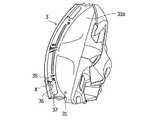
図1〜図8に示すように、本発明の実施形態に係る構造が適用される車両の車体前部1には、フロントウインドガラス2が車室内Rの車両前方側に傾斜して配設されており、当該フロントウインドガラス2の車両下方位置には、インストルメントパネル3が車両幅方向の全幅にわたって設けられている。このインストルメントパネル3の意匠面となる先端部31側の上面(天井面)31aには、図4に示すように、フロントウインドガラス2に対して交差する方向へ延びる角度の付いた傾斜面32が設けられており、該傾斜面32は、図1及び図2の破線で示す領域に形成され、衝突時に発生するフロントウインドガラス2からの衝突エネルギーに対して支持面となる部分である。なお、このような傾斜面32の最良の形態は、フロントウインドガラス2に対して、面直の方向に傾きを持つ面である。 As shown in FIGS. 1 to 8, a
本実施形態の構造では、図4に示すように、インストルメントパネル3の先端部31側の上面31aと傾斜面32との境界線(境目)には、これら先端部31の上面31a及び傾斜面32よりも剛性を低く構成した脆弱部33が設けられている。この脆弱部33は、衝突時において、インストルメントパネル3の先端部31の変形起点となる部分であり、フロントウインドガラス2を通じて車室内Rに侵入してくる歩行者の衝突エネルギーを傾斜面32が支持面となって受け、該傾斜面32よりも先端側のインストルメントパネル3の先端部31が脆弱部33を起点として車両下方へ移動するたわみ変形を起こすような状態となり、このたわみ変形によって、衝突エネルギーを吸収するように構成されている。 In the structure of this embodiment, as shown in FIG. 4, the
脆弱部33は、図4に示すように、インストルメントパネル3の先端部31側の裏面31bに切欠き34を設けることによって形成されており、該切欠き34は、インストルメントパネル3の先端部31の一部を切欠くことにより設けられている。切欠き34の設置は、インストルメントパネル3の成形性を損なうことなく、脆弱部33の形成が可能であり、かつ、通常走行時は、車体前部1から車両後方側へ伝達される振動が切欠き34で遮断されるからである。
しかも、脆弱部33は、フロントウインドガラス2の傾斜面に沿わせながら、インストルメントパネル3の先端部31の車両幅方向に沿って延在して設けられている。脆弱部33が車両幅方向へ延在していることによって、フロントウインドガラス2からの衝突荷重が、脆弱部33を設けたインストルメントパネル3の先端部31の一部に集中するということは起こらず、幅を持ったたわみ変形の起点がインストルメントパネル3の先端部31に形成されることになり、意図しない箇所において、インストルメントパネル3の先端部31の変形の発生が抑制されるようになっている。As shown in FIG. 4, the
Moreover, the
また、本実施形態のインストルメントパネル3の傾斜面32は、図4に示すように、当該インストルメントパネル3の先端部31側の上面31aの車両高さ方向における頂点部Tから車両下方へ向かって設けられており、脆弱部33は、当該頂点部Tに設けられている。このような位置関係にすることによって、衝突時のインストルメントパネル3の先端部31のたわみ変形の方向が明確になり、フロントウインドガラス2からの衝突エネルギーによってインストルメントパネル3の先端部31が折れやすく、インストルメントパネル3の先端部31の変形が促進されるようになっている。 Further, as shown in FIG. 4, the
さらに、本実施形態の車体前部1に位置する車体側のカウルパネル(もしくはダッシュパネル)11には、図4、図6及び図7に示すように、車両後方へ向かって突出する片持ち支持構造の固定部となるL字状の固定ブラケット12が設けられており、傾斜面32よりも車両前方側のインストルメントパネル3の先端部31を固定ブラケット12に係止させることによって、インストルメントパネル3の先端部31が車体側のカウルパネル11に固定されるようになっている。そのため、固定ブラケット12は、カウルパネル11の車両幅方向に間隔を空けて複数個(本実施形態では3個)設けられており、カウルパネル11に沿って車両下方へ延び、かつ溶接Wによってカウルパネル11に固定される固定片12aと、インストルメントパネル3の先端部31に沿って車両後方へ向かいながら斜め上方に延び、かつインストルメントパネル3の先端部31の係合部(後述する)に自由端としての後端部分が挟持される支持片12bとから構成されている。
したがって、衝突時にフロントウインドガラス2を介してインストルメントパネル3の先端部31が受ける衝突エネルギーによって、インストルメントパネル3の先端部31が車両下方へ移動する際に、カウルパネル11側の固定ブラケット12も連動して下方移動を起こすことになり、インストルメントパネル3の先端部31の変形が助長されることになる。Furthermore, the cowl panel (or dash panel) 11 on the vehicle body side located at the vehicle
Therefore, when the
一方、インストルメントパネル3の先端部31の裏面31bであって、固定ブラケット12と対応する複数箇所には、図3〜図5に示すように、係合部となる上下部係止片35,36が上下方向で互いに間隔を空けてそれぞれ設けられており、上下方向の間隔は、挟持する固定ブラケット12の支持片12bの板厚と対応する大きさに設定されている。上部係止片35は、車両前方及び車両下方へ延びながら、車両幅方向に間隔を空けて配置される複数枚のブレードから構成されている。そして、下部係止片36は、断面略U字状を有し、上端部が互いに向き合う方向へ延出した形状に形成され、固定ブラケット12の支持片12bと面接触するようになっている。これにより、上下部係止片35,36が係止した固定ブラケット12の支持片12bを上下からしっかりと挟持するように構成されている。 On the other hand, on the
また、インストルメントパネル3の先端部31と固定ブラケット12の支持片12bとの上下間には、図4に示すように、車両下方へ向かって変形するインストルメントパネル3の先端部31が固定ブラケット12の支持片12bと接触しないようにするための隙間Sが設けられている。この隙間Sが設けられていることにより、フロントウインドガラス2からの衝突エネルギーでインストルメントパネル3の先端部31が車両下方へ移動する際に、インストルメントパネル3の先端部31が固定ブラケット12の支持片12bに当たらず、支持片12bがインストルメントパネル3の先端部31の変形を邪魔するということは無くなり、インストルメントパネル3の先端部31が最大限に変形することが可能になっている。 Further, as shown in FIG. 4, the
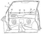
さらに、傾斜面32と固定ブラケット12の支持片12bとの間に位置するインストルメントパネル3の先端部31側の上面31aには、図1〜図5に示すように、別体のカバー(例えば、スピーカーカバー)4によって覆われる開口部37が設けられている。そして、カバー4の車両前方側の裏面には、車両前方へ向かって延びる引っ掛け部41が設けられ、カバー4の車両後方側の裏面には、車両下方へ向かって垂直に延びる係止部42が設けられている。引っ掛け部41は、断面L字状に形成されており、引っ掛け部41の先端側は、フロントウインドガラス2の面と略平行に配置されている。このようなカバー4は、引っ掛け部41及び係止部42を開口部37の周縁部に係合させることによって、インストルメントパネル3の先端部31側の上面31aに面一な状態で取付けられている。なお、開口部37の周囲の先端部31側の上面31aは、一段低く形成されており、カバー4の外周部が載せられるようになっている。また、開口部37の車両前方側の周縁部は、図8に示すように、車両下方へ向かって延びており、その中間部分には、カバー4の引っ掛け部41の先端部分を差し込む複数個の差込穴38が設けられている。
したがって、フロントウインドガラス2からの衝突エネルギーによりインストルメントパネル3の先端部31が車両下方へ移動する際に、カバー4の車両前方側は、開口部37の周縁部から外れることなく、引っ掛け部41が差込穴38に引っ掛かったままで当該先端部31の下方移動及び変形に追従し、過荷重時にはカバー4の車両後方側の係止部42が開口部37の周縁部から外れることで、インストルメントパネル3の先端部31の下方移動を邪魔しないようになっている。また、カバー4が外れた後は、インストルメントパネル3の先端部31側の上面31aに開口部37が露出し、インストルメントパネル3の先端部31の下方移動が助長されるようになっている。このため、インストルメントパネル3の先端部31においては、図8に示すように、脆弱部33から先端部31の前端部分(固定ブラケット12の固定片12a)の範囲が低剛性領域(衝突エネルギーの吸収領域)Lとなり、脆弱部33から車両後方部分の範囲が高剛性領域(剛性保持領域)Hとなっている。Further, as shown in FIGS. 1 to 5, a separate cover (for example, a
Therefore, when the
このように、本発明の実施形態に係るインストルメントパネル3の構造を備えた車両において、歩行者などの衝突時に車体前部1のフロントウインドガラス2を介して衝突荷重が図8の矢印Fで示す方向からインストルメントパネル3の先端部31に掛かった時には、当該先端部31が鎖線で示すように脆弱部33を起点として車両下方へ移動する。この先端部31の下方移動に連動して、固定ブラケット12の支持片12bが図4の鎖線で示すように固定片12aを起点として車両下方へ移動する。また、先端部31の下方移動に追従して、車両後方側の係止部42が開口部37の周縁部から外れ、カバー4が鎖線で示すように車両前方側の引っ掛け部41を起点として車両上方へ移動する。
したがって、本発明の実施形態に係るインストルメントパネル3の構造によれば、車両下方への移動時にインストルメントパネル3の先端部31が、固定ブラケット12やカバー4に邪魔されることなく、たわみ変形などを最大限に起こすことが確保されるため、衝突エネルギーを効果的に吸収することが可能となり、歩行者保護性能が向上することになる。Thus, in the vehicle having the structure of the
Therefore, according to the structure of the
以上、本発明の実施の形態につき述べたが、本発明は既述の実施の形態に限定されるものではなく、本発明の技術的思想に基づいて各種の変形及び変更が可能である。 While the embodiments of the present invention have been described above, the present invention is not limited to the above-described embodiments, and various modifications and changes can be made based on the technical idea of the present invention.
例えば、既述の実施の形態では、インストルメントパネル3の先端部31の裏面31bに切欠き34を設けることによって脆弱部33が形成されているが、インストルメントパネル3の先端部31の上面31aの板厚を薄肉に形成することによって脆弱部33が形成されていても良い。このような薄肉の脆弱部33によれば、通常状態時では、車室内Rにおいて乗員に近い車両後方側のインストルメントパネル3の上面は乗員が触れる可能性があっても、ベカツキなどを起こすことがない安定した品質を保持している一体化のインストルメントパネル3を搭載することができる。
また、既述の実施の形態では、上下部係止片35,36の間に固定ブラケット12の支持片12bを挟持することによって、インストルメントパネル3の先端部31がカウルパネル11に固定されているが、固定ブラケット12の支持片12bに確実に係止することが可能であれば、インストルメントパネル3側の係止部がボックス形状であっても良い。For example, in the above-described embodiment, the
Further, in the above-described embodiment, the
1 車体前部
2 フロントウインドガラス
3 インストルメントパネル
4 カバー
11 カウルパネル(車体)
12 固定ブラケット(固定部)
12a 固定片
12b 支持片
31 インストルメントパネルの先端部
31a 上面
31b 裏面
32 傾斜面
33 脆弱部
34 切欠き
35 上部係止片
36 下部係止片
37 開口部
38 差込穴
41 引っ掛け部
42 係止部
R 車室内
S 隙間
T 頂点部DESCRIPTION OF
12 Fixing bracket (fixing part)
Claims (9)
Translated fromJapanese前記インストルメントパネルの先端部側の上面と前記傾斜面との境界線には、脆弱部が設けられていることを特徴とするインストルメントパネルの構造。An inclined surface extending in a direction intersecting the front window glass is provided on the upper surface of the instrument panel located on the lower side of the front window glass.
A structure of the instrument panel, wherein a weakened portion is provided at a boundary line between the upper surface on the distal end side of the instrument panel and the inclined surface.
Priority Applications (3)
| Application Number | Priority Date | Filing Date | Title |
|---|---|---|---|
| JP2013156714AJP2015024784A (en) | 2013-07-29 | 2013-07-29 | Structure of instrument panel |
| DE102014109969.9ADE102014109969B4 (en) | 2013-07-29 | 2014-07-16 | Dashboard structure |
| CN201410363757.7ACN104340070A (en) | 2013-07-29 | 2014-07-28 | Structure of instrument board |
Applications Claiming Priority (1)
| Application Number | Priority Date | Filing Date | Title |
|---|---|---|---|
| JP2013156714AJP2015024784A (en) | 2013-07-29 | 2013-07-29 | Structure of instrument panel |
Publications (1)
| Publication Number | Publication Date |
|---|---|
| JP2015024784Atrue JP2015024784A (en) | 2015-02-05 |
Family
ID=52274159
Family Applications (1)
| Application Number | Title | Priority Date | Filing Date |
|---|---|---|---|
| JP2013156714APendingJP2015024784A (en) | 2013-07-29 | 2013-07-29 | Structure of instrument panel |
Country Status (3)
| Country | Link |
|---|---|
| JP (1) | JP2015024784A (en) |
| CN (1) | CN104340070A (en) |
| DE (1) | DE102014109969B4 (en) |
Cited By (2)
| Publication number | Priority date | Publication date | Assignee | Title |
|---|---|---|---|---|
| CN105882419A (en)* | 2016-05-27 | 2016-08-24 | 金龙联合汽车工业(苏州)有限公司 | Coach instrument desk fixing structure |
| US11643039B2 (en) | 2021-03-22 | 2023-05-09 | Toyota Jidosha Kabushiki Kaisha | Instrument panel |
Families Citing this family (3)
| Publication number | Priority date | Publication date | Assignee | Title |
|---|---|---|---|---|
| JP7275644B2 (en)* | 2019-02-26 | 2023-05-18 | トヨタ自動車株式会社 | head-up display device |
| CN113928259B (en)* | 2021-09-01 | 2023-06-06 | 浙江吉利控股集团有限公司 | Vehicle collision buffer device and vehicle |
| FR3134051A1 (en)* | 2022-04-05 | 2023-10-06 | Psa Automobiles Sa | Dashboard for motor vehicle |
Citations (23)
| Publication number | Priority date | Publication date | Assignee | Title |
|---|---|---|---|---|
| JPS4839300Y1 (en)* | 1968-05-22 | 1973-11-19 | ||
| JPS5261823U (en)* | 1975-10-31 | 1977-05-07 | ||
| JPS5261822U (en)* | 1975-10-31 | 1977-05-07 | ||
| JPS5261824U (en)* | 1975-10-31 | 1977-05-07 | ||
| JPS5691151U (en)* | 1979-12-17 | 1981-07-21 | ||
| JPS579628U (en)* | 1980-06-19 | 1982-01-19 | ||
| JPS5737024A (en)* | 1980-08-12 | 1982-03-01 | Nissan Motor Co Ltd | Construction of instrument panel for automobile |
| JPS62117156U (en)* | 1986-01-17 | 1987-07-25 | ||
| JPS63104234U (en)* | 1986-12-26 | 1988-07-06 | ||
| JPH0585226A (en)* | 1991-09-30 | 1993-04-06 | Mazda Motor Corp | Instrument panel structure for automobile |
| JPH0594022U (en)* | 1992-05-29 | 1993-12-21 | マツダ株式会社 | Vehicle instrument panel structure |
| JPH0761308A (en)* | 1993-08-30 | 1995-03-07 | Mazda Motor Corp | Impact absorbing structure for automobile |
| JP2005035325A (en)* | 2003-07-16 | 2005-02-10 | Toyota Motor Corp | Instrument panel structure of vehicle |
| JP2005119469A (en)* | 2003-10-16 | 2005-05-12 | Inoac Corp | Vehicular air duct |
| JP2006082675A (en)* | 2004-09-16 | 2006-03-30 | Toyota Auto Body Co Ltd | Mounting structure of instrument panel for vehicle |
| JP2006182158A (en)* | 2004-12-27 | 2006-07-13 | Toyoda Gosei Co Ltd | Airbag cover molding method |
| US7201434B1 (en)* | 2005-11-04 | 2007-04-10 | Cadence Innovation Llc | Energy-absorbing bolster for an automotive instrument panel assembly |
| JP2007137257A (en)* | 2005-11-18 | 2007-06-07 | Honda Motor Co Ltd | Vehicle collision object protection structure |
| JP2009018612A (en)* | 2007-07-10 | 2009-01-29 | Toyoda Gosei Co Ltd | Center cluster panel for vehicles |
| JP2009248757A (en)* | 2008-04-07 | 2009-10-29 | Toyota Auto Body Co Ltd | Mounting structure of instrument panel |
| JP2010036853A (en)* | 2008-08-08 | 2010-02-18 | Mazda Motor Corp | Instrument panel structure |
| JP2010047076A (en)* | 2008-08-20 | 2010-03-04 | Mazda Motor Corp | Vehicular front body structure |
| JP2010064709A (en)* | 2008-09-12 | 2010-03-25 | Denso Corp | Head-up display |
Family Cites Families (5)
| Publication number | Priority date | Publication date | Assignee | Title |
|---|---|---|---|---|
| JP4329469B2 (en)* | 2003-09-29 | 2009-09-09 | マツダ株式会社 | Front body structure of the vehicle |
| JP5157353B2 (en)* | 2007-01-22 | 2013-03-06 | 日産自動車株式会社 | Vehicle cowl structure |
| JP5020016B2 (en)* | 2007-10-02 | 2012-09-05 | マツダ株式会社 | Structure around the instrument panel of a car |
| FR2946948B1 (en)* | 2009-06-19 | 2015-09-04 | Faurecia Interieur Ind | DASHBOARD OF MOTOR VEHICLE AGENCY TO DEFORM IN CASE OF SHOCK |
| DE102011009605B4 (en)* | 2011-01-27 | 2014-11-27 | Audi Ag | Arrangement of an instrument panel in the interior of a motor vehicle |
- 2013
- 2013-07-29JPJP2013156714Apatent/JP2015024784A/enactivePending
- 2014
- 2014-07-16DEDE102014109969.9Apatent/DE102014109969B4/enactiveActive
- 2014-07-28CNCN201410363757.7Apatent/CN104340070A/enactivePending
Patent Citations (23)
| Publication number | Priority date | Publication date | Assignee | Title |
|---|---|---|---|---|
| JPS4839300Y1 (en)* | 1968-05-22 | 1973-11-19 | ||
| JPS5261823U (en)* | 1975-10-31 | 1977-05-07 | ||
| JPS5261822U (en)* | 1975-10-31 | 1977-05-07 | ||
| JPS5261824U (en)* | 1975-10-31 | 1977-05-07 | ||
| JPS5691151U (en)* | 1979-12-17 | 1981-07-21 | ||
| JPS579628U (en)* | 1980-06-19 | 1982-01-19 | ||
| JPS5737024A (en)* | 1980-08-12 | 1982-03-01 | Nissan Motor Co Ltd | Construction of instrument panel for automobile |
| JPS62117156U (en)* | 1986-01-17 | 1987-07-25 | ||
| JPS63104234U (en)* | 1986-12-26 | 1988-07-06 | ||
| JPH0585226A (en)* | 1991-09-30 | 1993-04-06 | Mazda Motor Corp | Instrument panel structure for automobile |
| JPH0594022U (en)* | 1992-05-29 | 1993-12-21 | マツダ株式会社 | Vehicle instrument panel structure |
| JPH0761308A (en)* | 1993-08-30 | 1995-03-07 | Mazda Motor Corp | Impact absorbing structure for automobile |
| JP2005035325A (en)* | 2003-07-16 | 2005-02-10 | Toyota Motor Corp | Instrument panel structure of vehicle |
| JP2005119469A (en)* | 2003-10-16 | 2005-05-12 | Inoac Corp | Vehicular air duct |
| JP2006082675A (en)* | 2004-09-16 | 2006-03-30 | Toyota Auto Body Co Ltd | Mounting structure of instrument panel for vehicle |
| JP2006182158A (en)* | 2004-12-27 | 2006-07-13 | Toyoda Gosei Co Ltd | Airbag cover molding method |
| US7201434B1 (en)* | 2005-11-04 | 2007-04-10 | Cadence Innovation Llc | Energy-absorbing bolster for an automotive instrument panel assembly |
| JP2007137257A (en)* | 2005-11-18 | 2007-06-07 | Honda Motor Co Ltd | Vehicle collision object protection structure |
| JP2009018612A (en)* | 2007-07-10 | 2009-01-29 | Toyoda Gosei Co Ltd | Center cluster panel for vehicles |
| JP2009248757A (en)* | 2008-04-07 | 2009-10-29 | Toyota Auto Body Co Ltd | Mounting structure of instrument panel |
| JP2010036853A (en)* | 2008-08-08 | 2010-02-18 | Mazda Motor Corp | Instrument panel structure |
| JP2010047076A (en)* | 2008-08-20 | 2010-03-04 | Mazda Motor Corp | Vehicular front body structure |
| JP2010064709A (en)* | 2008-09-12 | 2010-03-25 | Denso Corp | Head-up display |
Cited By (2)
| Publication number | Priority date | Publication date | Assignee | Title |
|---|---|---|---|---|
| CN105882419A (en)* | 2016-05-27 | 2016-08-24 | 金龙联合汽车工业(苏州)有限公司 | Coach instrument desk fixing structure |
| US11643039B2 (en) | 2021-03-22 | 2023-05-09 | Toyota Jidosha Kabushiki Kaisha | Instrument panel |
Also Published As
| Publication number | Publication date |
|---|---|
| DE102014109969A1 (en) | 2015-01-29 |
| DE102014109969A8 (en) | 2020-06-18 |
| DE102014109969B4 (en) | 2020-09-03 |
| CN104340070A (en) | 2015-02-11 |
Similar Documents
| Publication | Publication Date | Title |
|---|---|---|
| JP4366919B2 (en) | Vehicle front deck structure | |
| JP2015024784A (en) | Structure of instrument panel | |
| JP2000038160A (en) | Windshield support structure | |
| JP5630721B2 (en) | Body front structure | |
| KR20080052754A (en) | Cowl side part reinforcement structure of vehicle | |
| JP2008114808A (en) | Support structure of supported body | |
| JP5882163B2 (en) | Radiator grill | |
| CN204340702U (en) | The impact absorbing structure of the instrument carrier panel of vehicle | |
| JP5359104B2 (en) | Automotive door trim structure | |
| CN103648891B (en) | Vehicle Front Structure | |
| JP5614663B2 (en) | Body front structure | |
| JP2019093823A (en) | Cowl top garnish support structure | |
| JP5656621B2 (en) | Mounting structure for in-vehicle equipment | |
| JP2022049957A (en) | Vehicle structure | |
| JP5962532B2 (en) | Temporary holding structure for roofing | |
| JP5365912B2 (en) | Cowl top garnish structure | |
| JP6610119B2 (en) | Cowl top garnish structure | |
| JP2009045996A (en) | Cowl structure of four wheel vehicle | |
| JP5520081B2 (en) | Car cowl structure | |
| JP2009040389A (en) | Body front structure | |
| JP6508166B2 (en) | Cowl top garnish structure | |
| JP6229889B2 (en) | Instrument panel support structure | |
| JP6516088B2 (en) | instrument panel | |
| JP4666144B2 (en) | Vehicle cowl box structure | |
| JP6217926B2 (en) | Front deck structure of the vehicle |
Legal Events
| Date | Code | Title | Description |
|---|---|---|---|
| A621 | Written request for application examination | Free format text:JAPANESE INTERMEDIATE CODE: A621 Effective date:20160315 | |
| A977 | Report on retrieval | Free format text:JAPANESE INTERMEDIATE CODE: A971007 Effective date:20170126 | |
| A131 | Notification of reasons for refusal | Free format text:JAPANESE INTERMEDIATE CODE: A131 Effective date:20170131 | |
| A521 | Request for written amendment filed | Free format text:JAPANESE INTERMEDIATE CODE: A523 Effective date:20170309 | |
| A131 | Notification of reasons for refusal | Free format text:JAPANESE INTERMEDIATE CODE: A131 Effective date:20170801 | |
| A521 | Request for written amendment filed | Free format text:JAPANESE INTERMEDIATE CODE: A523 Effective date:20170928 | |
| A02 | Decision of refusal | Free format text:JAPANESE INTERMEDIATE CODE: A02 Effective date:20180202 |