JP2015023554A - Communication device and communication system - Google Patents
Communication device and communication systemDownload PDFInfo
- Publication number
- JP2015023554A JP2015023554AJP2013152945AJP2013152945AJP2015023554AJP 2015023554 AJP2015023554 AJP 2015023554AJP 2013152945 AJP2013152945 AJP 2013152945AJP 2013152945 AJP2013152945 AJP 2013152945AJP 2015023554 AJP2015023554 AJP 2015023554A
- Authority
- JP
- Japan
- Prior art keywords
- phase
- signal
- transmission signal
- unique word
- transmission
- Prior art date
- Legal status (The legal status is an assumption and is not a legal conclusion. Google has not performed a legal analysis and makes no representation as to the accuracy of the status listed.)
- Pending
Links
Images


Landscapes
- Mobile Radio Communication Systems (AREA)
- Radio Transmission System (AREA)
Abstract
Translated fromJapaneseDescription
Translated fromJapanese本発明は、通信装置、および通信システムに関する。 The present invention relates to a communication device and a communication system.
近年、アレーアンテナ(array antenna)やMIMO(Multiple-Input and Multiple-Output)を用いた空間センサ(sensor)が開発されている。上記空間センサに係る技術としては、例えば、特許文献1に記載の技術や特許文献2に記載の技術が挙げられる。 In recent years, a spatial sensor using an array antenna or MIMO (Multiple-Input and Multiple-Output) has been developed. Examples of the technology related to the space sensor include the technology described in
通常のMIMOにおける送信信号は、例えば、送信側のアンテナ(以下、「送信アンテナ」と示す。)から同時に送信される。また、通常のMIMOでは、高速化、大容量化のために、OFDM(Orthogonal Frequency Division Multiplexing)により変調された信号(以下、「OFDM信号」と示す。)が用いられている。MIMOを用いる場合には、チャネル推定(channel estimation)が必要であり、チャネル推定の精度を高めるためには、送信側の通信装置と、受信側の通信装置との間で同期をとることが望ましい。ここで、OFDMでは、例えば、ショートプリアンブル(short preamble)や、パイロット信号(pilot signal)、カードインターバル(guard interval)などを用いて送信側の通信装置と、受信側の通信装置との間で同期がとられている。 Transmission signals in normal MIMO are transmitted simultaneously from, for example, an antenna on the transmission side (hereinafter referred to as “transmission antenna”). Also, in normal MIMO, a signal modulated by OFDM (Orthogonal Frequency Division Multiplexing) (hereinafter referred to as “OFDM signal”) is used in order to increase the speed and capacity. When MIMO is used, channel estimation is necessary, and in order to improve the accuracy of channel estimation, it is desirable to synchronize between the communication device on the transmission side and the communication device on the reception side. . Here, in OFDM, for example, a synchronization is performed between a communication device on the transmission side and a communication device on the reception side using a short preamble, a pilot signal, a card interval (guard interval), and the like. Has been taken.
ここで、OFDMを用いる場合には、通信に係るデバイス(device)(例えば送信機回路など)のコスト(cost)が大きく、また、使用可能な周波数帯域にも制限が存在しうる。また、例えばMIMOを用いた空間センサでは、実際にはOFDM信号のような高速な信号は必要なく、より低速な信号を用いれば十分である。よって、OFDMを用いずに、より低速な信号を用いることが可能な、MIMOを用いた空間センサが望まれている。 Here, in the case of using OFDM, the cost of a device (for example, a transmitter circuit) related to communication is large, and there may be a restriction on a usable frequency band. For example, in a spatial sensor using MIMO, a high-speed signal such as an OFDM signal is not actually required, and a lower-speed signal is sufficient. Therefore, a spatial sensor using MIMO that can use a slower signal without using OFDM is desired.
しかしながら、MIMOにおいて低速な信号を用いる場合には、キャリアオフセット(carrier offset)(送信側の通信装置と、受信側の通信装置における搬送波周波数のずれ)が信号の伝送速度に対して等価的に大きくなることから、チャネル推定を行うことが困難となる。 However, when a low-speed signal is used in MIMO, the carrier offset (the carrier frequency deviation between the transmission-side communication device and the reception-side communication device) is equivalently larger than the signal transmission rate. Therefore, it becomes difficult to perform channel estimation.
本発明は、上記問題に鑑みてなされたものであり、本発明の目的とするところは、MIMOにおけるチャネル推定の精度を向上させることが可能な、新規かつ改良された通信装置、および通信システムを提供することにある。 The present invention has been made in view of the above problems, and an object of the present invention is to provide a new and improved communication apparatus and communication system capable of improving the accuracy of channel estimation in MIMO. It is to provide.
上記目的を達成するために、本発明の第1の観点によれば、複数の送信アンテナから切り替えて送信される、上記送信アンテナに対応するユニークなユニークワードを含む送信信号が含まれうる、受信アンテナにより受信された信号が復調された受信信号を処理する通信装置であって、上記受信信号から切り替えて送信される上記送信信号の切替区間を検出することによって、上記送信信号を検出する信号検出部と、検出された送信信号に含まれるユニークワードの位相回転量によって、検出された送信信号を判別する信号判別部と、判別された送信信号に含まれるユニークワードの位相回転量と、上記判別された送信信号に対応する基準位相回転量との位相回転差分に基づいて、上記判別された送信信号の位相を補正する第1位相補正部と、上記位相回転差分に基づいて位相が補正された送信信号と位相の初期値との誤差を補正する第2位相補正部と、位相の誤差が補正された上記判別された送信信号と、既知の信号とに基づいて、チャネルを推定するチャネル推定部と、
を備え、上記ユニークワードの前後には、位相の回転方向が上記ユニークワードの位相の回転方向に対して反転されたデータが付加され、上記信号判別部は、上記反転されたデータが付加された上記ユニークワードにおける位相変化量に基づいて、上記送信信号に含まれる上記ユニークワードを特定し、上記反転されたデータが付加された上記ユニークワードは、位相回転の2周期分に該当し、上記2周期分のうち、上記ユニークワードは、位相回転の1周期分に該当し、上記ユニークワードの前後に付加される上記反転されたデータは、上記ユニークワードに該当する上記1周期分の前後の1周期の半分の区間の位相の回転方向が、反転されたデータである通信装置が提供される。In order to achieve the above object, according to the first aspect of the present invention, a reception signal including a unique unique word corresponding to the transmission antenna, which is transmitted by switching from a plurality of transmission antennas, may be included. A communication apparatus for processing a reception signal obtained by demodulating a signal received by an antenna, and detecting the transmission signal by detecting a switching section of the transmission signal that is switched from the reception signal and transmitted. And a signal discriminating unit for discriminating the detected transmission signal based on the phase rotation amount of the unique word contained in the detected transmission signal, the phase rotation amount of the unique word contained in the discriminated transmission signal, and the discrimination A first phase correction unit that corrects the phase of the determined transmission signal based on a phase rotation difference from a reference phase rotation amount corresponding to the transmitted signal. A second phase correction unit that corrects an error between a transmission signal whose phase is corrected based on the phase rotation difference and an initial value of the phase; the determined transmission signal whose phase error is corrected; and a known signal A channel estimation unit for estimating a channel based on
Before and after the unique word, data in which the rotation direction of the phase is inverted with respect to the rotation direction of the phase of the unique word is added, and the signal discrimination unit is added with the inverted data Based on the phase change amount in the unique word, the unique word included in the transmission signal is specified, and the unique word to which the inverted data is added corresponds to two periods of phase rotation, and the 2 Among the periods, the unique word corresponds to one period of phase rotation, and the inverted data added before and after the unique word is 1 before and after the one period corresponding to the unique word. There is provided a communication device in which the phase rotation direction of a half period is inverted data.
かかる構成によって、フレーム同期(frame synchronization)、キャリア同期(carrier synchronization)、およびタイミング同期(timing synchronization)とを図った上でチャネルを推定することができる。よって、かかる構成によって、MIMOにおけるチャネル推定の精度を向上させることができる。 With this configuration, it is possible to estimate a channel while achieving frame synchronization, carrier synchronization, and timing synchronization. Therefore, with this configuration, it is possible to improve the accuracy of channel estimation in MIMO.
また、上記第1位相補正部は、上記位相回転差分を、上記判別された送信信号に乗算することによって、上記判別された送信信号の位相を補正してもよい。 The first phase correction unit may correct the phase of the determined transmission signal by multiplying the determined transmission signal by the phase rotation difference.
また、複数の上記受信アンテナと、上記受信アンテナそれぞれが受信した信号を復調する受信部と、をさらに備え、上記信号検出部は、上記受信部から伝達される上記受信信号から、上記送信信号を検出してもよい。 And a reception unit that demodulates signals received by each of the reception antennas, and the signal detection unit converts the transmission signal from the reception signal transmitted from the reception unit. It may be detected.
また、複数の上記送信アンテナと、上記送信アンテナに対応する上記送信信号を切り替えて送信させる送信部と、をさらに備えていてもよい。 Moreover, you may further provide the said transmission antenna and the transmission part which switches and transmits the said transmission signal corresponding to the said transmission antenna.
また、上記目的を達成するために、本発明の第2の観点によれば、送信アンテナに対応するユニークなユニークワードを含む送信信号が送信される、複数の送信アンテナと、上記送信アンテナに対応する上記送信信号を切り替えて送信させる送信部と、を備え、上記送信部は、上記ユニークワードの前後に、位相の回転方向が上記ユニークワードの位相の回転方向に対して反転されたデータを付加し、上記反転されたデータが付加された上記ユニークワードは、位相回転の2周期分に該当し、上記2周期分のうち、上記ユニークワードは、位相回転の1周期分に該当し、上記ユニークワードの前後に付加される上記反転されたデータは、上記ユニークワードに該当する上記1周期分の前後の1周期の半分の区間の位相の回転方向が、反転されたデータである通信装置が提供される。 In order to achieve the above object, according to the second aspect of the present invention, a plurality of transmission antennas for transmitting a transmission signal including a unique unique word corresponding to the transmission antenna and the transmission antenna are supported. A transmission unit that switches the transmission signal to be transmitted, and the transmission unit adds data in which the rotation direction of the phase is inverted with respect to the rotation direction of the phase of the unique word before and after the unique word. The unique word to which the inverted data is added corresponds to two periods of phase rotation. Of the two periods, the unique word corresponds to one period of phase rotation, and the unique word In the inverted data added before and after the word, the rotation direction of the phase of the half of one period before and after the one period corresponding to the unique word is inverted. A data communication device is provided.
かかる構成によって、第1の送信アンテナからの第1送信信号の送信と、第2の送信アンテナからの第2送信信号の送信との切り替えを実現することができる。 With this configuration, switching between transmission of the first transmission signal from the first transmission antenna and transmission of the second transmission signal from the second transmission antenna can be realized.
また、上記目的を達成するために、本発明の第3の観点によれば、送信アンテナに対応するユニークなユニークワードを含む送信信号を、複数の送信アンテナから切り替えて送信する第1の通信装置と、上記送信信号が含まれうる、受信アンテナにより受信された信号が復調された受信信号を処理する第2通信装置と、を有する通信システムであって、上記第1の通信装置は、複数の送信アンテナと、上記送信アンテナに対応する送信信号を切り替えて送信させる送信部と、を備え、上記送信部は、上記ユニークワードの前後に、位相の回転方向が上記ユニークワードの位相の回転方向に対して反転されたデータを付加し、上記第2通信装置は、上記受信信号から切り替えて送信される上記送信信号の切替区間を検出することによって、上記送信信号を検出する信号検出部と、検出された送信信号に含まれるユニークワードの位相回転量によって、検出された送信信号を判別する信号判別部と、判別された送信信号に含まれるユニークワードの位相回転量と、上記判別された送信信号に対応する基準位相回転量との位相回転差分に基づいて、上記判別された送信信号の位相を補正する第1位相補正部と、上記位相回転差分に基づいて位相が補正された送信信号と位相の初期値との誤差を補正する第2位相補正部と、位相の誤差が補正された上記判別された送信信号と、既知の信号とに基づいて、チャネルを推定するチャネル推定部と、を備え、上記信号判別部は、上記反転されたデータが付加された上記ユニークワードにおける位相変化量に基づいて、上記送信信号に含まれる上記ユニークワードを特定し、上記反転されたデータが付加された上記ユニークワードは、位相回転の2周期分に該当し、上記2周期分のうち、上記ユニークワードは、位相回転の1周期分に該当し、上記ユニークワードの前後に付加される上記反転されたデータは、上記ユニークワードに該当する上記1周期分の前後の1周期の半分の区間の位相の回転方向が、反転されたデータである通信システムが提供される。 In order to achieve the above object, according to a third aspect of the present invention, a first communication apparatus that transmits a transmission signal including a unique unique word corresponding to a transmission antenna by switching from a plurality of transmission antennas. And a second communication device that processes the received signal obtained by demodulating the signal received by the receiving antenna, which may include the transmission signal, wherein the first communication device includes a plurality of A transmission unit, and a transmission unit that switches and transmits a transmission signal corresponding to the transmission antenna, and the transmission unit has a phase rotation direction before and after the unique word and a phase rotation direction of the unique word. Inverted data is added to the second communication device, and the second communication device detects the switching interval of the transmission signal that is transmitted by switching from the received signal. A signal detection unit that detects the transmission signal, a signal determination unit that determines the detected transmission signal based on the phase rotation amount of the unique word included in the detected transmission signal, and a unique word included in the determined transmission signal Based on the phase rotation difference between the phase rotation amount and the reference phase rotation amount corresponding to the determined transmission signal, a first phase correction unit that corrects the phase of the determined transmission signal, and the phase rotation difference Based on the second phase correction unit that corrects an error between the transmission signal whose phase is corrected based on the initial value of the phase, the determined transmission signal whose phase error is corrected, and the known signal, A channel estimation unit for estimating a channel, and the signal determination unit is included in the transmission signal based on a phase change amount in the unique word to which the inverted data is added. The unique word to which a unique word is specified and the inverted data is added corresponds to two phases of phase rotation. Of the two cycles, the unique word corresponds to one cycle of phase rotation. The inverted data added before and after the unique word is data in which the phase rotation direction of the half of one period before and after the one period corresponding to the unique word is inverted. A communication system is provided.
かかる構成によって、MIMOにおけるチャネル推定の精度を向上させることが可能な通信システムが実現される。 With this configuration, a communication system capable of improving the accuracy of channel estimation in MIMO is realized.
本発明によれば、MIMOにおけるチャネル推定の精度を向上させることができる。 According to the present invention, the accuracy of channel estimation in MIMO can be improved.
以下に添付図面を参照しながら、本発明の好適な実施の形態について詳細に説明する。なお、本明細書および図面において、実質的に同一の機能構成を有する構成要素については、同一の符号を付することにより重複説明を省略する。 Exemplary embodiments of the present invention will be described below in detail with reference to the accompanying drawings. In the present specification and drawings, components having substantially the same functional configuration are denoted by the same reference numerals, and redundant description is omitted.
(本発明の実施形態に係るチャネル推定方法の概要)
本発明の実施形態に係る通信装置の構成について説明する前に、本発明の実施形態に係るチャネル推定方法の概要について説明する。以下では、説明の簡単化のために、SISO(Single-Input and Single-Output)を例に挙げて、本発明の実施形態に係るチャネル推定方法の概要について説明する。なお、以下においてSISOを例に挙げて説明する本発明の実施形態に係るチャネル推定方法の概要は、MIMOにおいても本質的に同一である。(Outline of Channel Estimation Method According to Embodiment of the Present Invention)
Before describing the configuration of a communication apparatus according to an embodiment of the present invention, an overview of a channel estimation method according to an embodiment of the present invention will be described. In the following, for simplification of description, an outline of a channel estimation method according to an embodiment of the present invention will be described by taking SISO (Single-Input and Single-Output) as an example. The outline of the channel estimation method according to the embodiment of the present invention described below using SISO as an example is essentially the same in MIMO.
図1は、本発明の実施形態に係るチャネル推定方法の概要を説明するための説明図である。図1では、送信側の通信装置を「Tx」と示し、受信側の通信装置を「Rx」と示している。 FIG. 1 is an explanatory diagram for explaining an overview of a channel estimation method according to an embodiment of the present invention. In FIG. 1, the communication device on the transmission side is indicated as “Tx”, and the communication device on the reception side is indicated as “Rx”.
例えば図1において受信側の通信装置が受信する受信信号は、例えば下記の数式1で表される。ここで、数式1に示す“y(t)”は、受信信号を示し、数式1に示す“h11”は、マルチパス(multipath)の合成波を示している。また、数式1に示す“sp(t)”は、送信側の通信装置および受信側の通信装置において既知の信号を示しており、数式1に示すn(t)は、熱雑音を示している。For example, the received signal received by the receiving communication device in FIG. Here, “y (t)” shown in

受信側の通信装置は、受信信号を既知の信号sp(t)で割ることによって、例えば下記の数式2に示すように、チャネルを推定することができる。ここで、数式2に示す“n(t)/sp(t)”は、雑音成分であるので無視することが可能である。Receiving communication apparatus, by dividing the received signal by a known signal sp (t), for example, as shown in
しかしながら、例えば数式2に示すようにチャネルを推定する場合には、受信信号y(t)が既知の信号sp(t)と同じ時刻tに相当するビット列(bit stream)の変調信号でないと、正しいチャネル推定を行うことができない。よって、例えば数式2に示すようにチャネルを推定する場合において、チャネルの推定制度を向上させるためには、受信側の通信装置においてフレーム同期を行う必要がある。However, when estimating the channel, for example, as shown in
また、受信信号y(t)は、時間の経過と共に周波数回転を起こすため、受信側の通信装置では、同じ時刻tに相当するビット列の変調信号(送信側の通信装置から送信された送信信号)を受信信号y(t)から取り出すことができない。よって、例えば数式2に示すようにチャネルを推定する場合には、受信側の通信装置においてキャリア同期を行う必要がある。 In addition, since the received signal y (t) undergoes frequency rotation as time elapses, in the communication device on the reception side, a modulated signal of a bit string corresponding to the same time t (transmission signal transmitted from the communication device on the transmission side) Cannot be extracted from the received signal y (t). Therefore, for example, when estimating the channel as shown in
また、受信信号y(t)は、時間の経過と共にサンプルタイミング(sample timing)がずれるため、受信側の通信装置では、同じ時刻tに相当するビット列の変調信号(送信側の通信装置から送信された送信信号)を受信信号y(t)から取り出すことができない。よって、例えば数式2に示すようにチャネルを推定する場合には、受信側の通信装置においてタイミング同期を行う必要がある。 In addition, since the reception signal y (t) is shifted in sample timing with time, the reception side communication apparatus transmits a modulated signal of a bit string corresponding to the same time t (transmitted from the transmission side communication apparatus). Transmission signal) cannot be extracted from the reception signal y (t). Therefore, for example, when estimating the channel as shown in
MIMOにおいて例えば数式2に示すようにチャネルを推定する場合には、SISOを例に挙げて説明したように、受信側の通信装置において、フレーム同期と、キャリア同期と、タイミング同期とを図る必要がある。 For example, when estimating a channel as shown in
ここで、上述したように、OFDMでは、例えば、ショートプリアンブルや、パイロット信号、カードインターバルなどを用いて送信側の通信装置と、受信側の通信装置との間で同期がとられている。そのため、OFDMを用いる場合には、フレーム同期と、キャリア同期と、タイミング同期とを図ることができるので、MIMOにおけるチャネル推定の精度を向上させることが可能である。 Here, as described above, in OFDM, synchronization is established between a communication device on the transmission side and a communication device on the reception side using, for example, a short preamble, a pilot signal, a card interval, and the like. Therefore, when OFDM is used, frame synchronization, carrier synchronization, and timing synchronization can be achieved, so that it is possible to improve the accuracy of channel estimation in MIMO.
しかしながら、上述したように、OFDMを用いる場合には、通信に係るデバイスのコストが大きく、また、使用可能な周波数帯域にも制限が存在しうる。また、例えばMIMOを用いた空間センサを実現する場合には、OFDM信号のような高速の信号は必要ない。 However, as described above, when OFDM is used, the cost of a device related to communication is high, and there may be a limit on a usable frequency band. For example, when realizing a spatial sensor using MIMO, a high-speed signal such as an OFDM signal is not necessary.
そこで、本発明の実施形態に係るチャネル推定方法では、例えば、OFDMを用いず、またOFDM信号よりも低速な信号を用いる。より具体的には、本発明の実施形態に係るチャネル推定方法では、本発明の実施形態に係る送信側の通信装置(以下、「第1の通信装置」と示す場合がある。)が、例えば、IEEE802.15.4規格などで用いられているOQPSK(Offset Quadrature Phase Shift Keying)により変調されたOQPSK信号を、送信信号として送信する。 Therefore, in the channel estimation method according to the embodiment of the present invention, for example, OFDM is not used and a signal slower than the OFDM signal is used. More specifically, in the channel estimation method according to the embodiment of the present invention, the transmission-side communication apparatus (hereinafter, may be referred to as “first communication apparatus”) according to the embodiment of the present invention, for example. An OQPSK signal modulated by OQPSK (Offset Quadrature Phase Shift Keying) used in the IEEE 802.15.4 standard is transmitted as a transmission signal.
なお、本発明の実施形態に係る送信信号の変調方式は、上記に限られない。例えば、本発明の実施形態に係る送信信号は、π/4シフトQPSKにより変調された信号など、原点Oを通過する位相遷移が生じない様々な変調方式により変調された信号であってもよい。以下では、本発明の実施形態に係る送信信号が、OQPSK信号である場合を例に挙げる。 The transmission signal modulation scheme according to the embodiment of the present invention is not limited to the above. For example, the transmission signal according to the embodiment of the present invention may be a signal modulated by various modulation schemes that do not cause a phase transition passing through the origin O, such as a signal modulated by π / 4 shift QPSK. Below, the case where the transmission signal which concerns on embodiment of this invention is an OQPSK signal is mentioned as an example.
図2は、本発明の実施形態に係る送信信号の一例を説明するための説明図である。図2では、本発明の実施形態に係る送信信号が、OQPSK信号である場合を示している。図2に示すAは、OQPSK信号における位相遷移を示しており、図2に示すBは、OQPSKにおけるI−チャネルの信号とQ−チャネルの信号との関係を示している。 FIG. 2 is an explanatory diagram for explaining an example of a transmission signal according to the embodiment of the present invention. FIG. 2 shows a case where the transmission signal according to the embodiment of the present invention is an OQPSK signal. 2 shows the phase transition in the OQPSK signal, and B shown in FIG. 2 shows the relationship between the I-channel signal and the Q-channel signal in OQPSK.
図2のBに示すように、OQPSKでは、I−チャネルの信号の極性とQ−チャネルの信号の極性とが同時に変化しない。そのため、図2のAに示すように、OQPSKでは、原点Oを通過する位相遷移は生じない。つまり、OQPSKでは、“11”と“00”との間での位相遷移、および、“01”と“10”との間での位相遷移は生じない。また、OQPSKでは、位相変化の際に一定振幅で移動しない点が、例えばFSK(Frequency Shift Keying)などとは異なる。 As shown in FIG. 2B, in OQPSK, the polarity of the I-channel signal and the polarity of the Q-channel signal do not change simultaneously. Therefore, as shown in FIG. 2A, in OQPSK, a phase transition that passes through the origin O does not occur. That is, in OQPSK, the phase transition between “11” and “00” and the phase transition between “01” and “10” do not occur. Also, OQPSK is different from FSK (Frequency Shift Keying), for example, in that it does not move at a constant amplitude when the phase changes.
図3は、本発明の実施形態に係る送信信号の一例を説明するための説明図である。図3では、本発明の実施形態に係る送信信号が、OQPSK信号であり、帯域制限のためロールオフフィルタ(roll off filter)がかけられた場合における、信号点の移動の一例を示している。図3に示すAは、BT=1、ロールオフ率=0.5における信号点の移動の一例を示しており、図3に示すBは、BT=1、ロールオフ率=1における信号点の移動の一例を示している。ここで、“B”は、帯域幅を示し、“T”はシンボル長を示してる。例えば、規格化された帯域幅においてBT=1とされる場合には、周波数スペクトラムの第一ヌル(null)までの幅となる。 FIG. 3 is an explanatory diagram for explaining an example of a transmission signal according to the embodiment of the present invention. FIG. 3 shows an example of signal point movement when the transmission signal according to the embodiment of the present invention is an OQPSK signal and a roll-off filter is applied for band limitation. A shown in FIG. 3 shows an example of signal point movement at BT = 1 and roll-off rate = 0.5. B shown in FIG. 3 shows signal points at BT = 1 and roll-off rate = 1. An example of movement is shown. Here, “B” indicates a bandwidth, and “T” indicates a symbol length. For example, when BT = 1 in the standardized bandwidth, the frequency spectrum has a width up to the first null.
帯域制限のためにロールオフフィルタによりフィルタ処理が行われた場合には、図2に示すAとは信号点の移動の軌跡は異なるが、原点を通過する位相遷移は生じない。 When filter processing is performed by a roll-off filter to limit the band, the locus of signal point movement is different from A shown in FIG. 2, but no phase transition that passes through the origin occurs.
ここで、反時計回りに位相を変化させるデータ列(例えば“10”→“11”→“01”→“00”→“10”に変化するデータ列)と、時計回りに位相を変化させるデータ列(例えば“10”→“00”→“01”→“11”→
“10”に変化するデータ列)という、位相を一定方向に変化させるデータ列を考える。Here, a data string that changes the phase counterclockwise (for example, a data string that changes from “10” → “11” → “01” → “00” → “10”) and data that changes the phase clockwise. Column (for example, “10” → “00” → “01” → “11” →
Consider a data string that changes the phase in a certain direction (data string that changes to “10”).
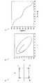
図4は、帯域制限をかけて位相を変化させた場合における、位相変化量の一例を示す説明図である。図4に示すAは、位相変化を反時計回りにした信号点の一例を示している。図4に示すBは、BT=1、ロールオフ率=0.5により帯域制限をかけた、位相変化を反時計回りにした信号点の一例を示している。図4に示すCは、図4のBの場合における、12倍のオーバーサンプルの位相変化量の一例を示している。 FIG. 4 is an explanatory diagram showing an example of the amount of phase change when the phase is changed with band limitation. A shown in FIG. 4 shows an example of signal points in which the phase change is counterclockwise. B shown in FIG. 4 shows an example of a signal point in which the phase change is counterclockwise with the band limited by BT = 1 and the roll-off rate = 0.5. C shown in FIG. 4 shows an example of the phase change amount of 12 times oversampling in the case of B of FIG.
図5は、帯域制限をかけて位相を変化させた場合における、位相変化量の他の例を示す説明図である。図5に示すAは、位相変化を時計回りにした信号点の一例を示している。図5に示すBは、BT=1、ロールオフ率=0.5により帯域制限をかけた、位相変化を時計回りにした信号点の一例を示している。図5に示すCは、図5のBの場合における、12倍のオーバーサンプルの位相変化量の一例を示している。 FIG. 5 is an explanatory diagram illustrating another example of the phase change amount when the phase is changed with band limitation. A shown in FIG. 5 shows an example of signal points in which the phase change is clockwise. B shown in FIG. 5 shows an example of signal points in which the phase is changed clockwise by applying band limitation with BT = 1 and roll-off rate = 0.5. C in FIG. 5 shows an example of the phase change amount of 12 times oversampling in the case of B in FIG.
例えばロールオフフィルタなどにより帯域制限をかけない場合には、図4のAや図5のAに示すように、信号点の軌跡は、正方形を描く。一方、例えばロールオフフィルタにより帯域制限をかけると信号点の軌跡は、図4のBや図5のBに示すように楕円を描く。帯域制限をかけた場合には、図4のBや図5のBに示すように、信号点の軌跡が楕円を描くため、図4のCや図5のCに示すように、位相は直線では変化しないが、4シンボルで位相が360[度]回転していることが分かる。 For example, when the band is not limited by a roll-off filter or the like, as shown in A of FIG. 4 or A of FIG. 5, the locus of signal points draws a square. On the other hand, for example, when band limitation is applied by a roll-off filter, the locus of signal points draws an ellipse as shown in B of FIG. 4 or B of FIG. When band limitation is applied, as shown in B of FIG. 4 and B of FIG. 5, the locus of the signal point draws an ellipse, and therefore the phase is a straight line as shown in C of FIG. 4 and C of FIG. Although it does not change, it can be seen that the phase is rotated 360 degrees by 4 symbols.
以下では、受信された本発明の実施形態に係る送信信号を処理する、本発明の実施形態に係る受信側の通信装置(以下、「第2の通信装置」と示す場合がある。)が、帯域制限のためにロールオフフィルタによるフィルタ処理を行う場合を例に挙げる。 In the following, a communication device on the receiving side according to an embodiment of the present invention (hereinafter, may be referred to as a “second communication device”) that processes a received transmission signal according to the embodiment of the present invention. An example of performing filter processing using a roll-off filter for band limitation will be described as an example.
また、本発明の実施形態に係るチャネル推定方法では、本発明の実施形態に係る受信側の通信装置(第2の通信装置)が、ユニークワード(後述する)を含む送信信号が含まれうる、受信アンテナにより受信された信号が復調された受信信号を処理し、フレーム同期と、キャリア同期と、タイミング同期とを図ることによって、MIMOにおけるチャネル推定を行う。 In the channel estimation method according to the embodiment of the present invention, the receiving-side communication device (second communication device) according to the embodiment of the present invention may include a transmission signal including a unique word (described later). The received signal obtained by demodulating the signal received by the receiving antenna is processed, and frame synchronization, carrier synchronization, and timing synchronization are performed to perform channel estimation in MIMO.
[1]本発明の実施形態に係る第1の通信装置(送信側の通信装置)における、本発明の実施形態に係るチャネル推定方法に係る処理
まず、本発明の実施形態に係る第1の通信装置における、本発明の実施形態に係るチャネル推定方法に係る処理について説明する。以下では、本発明の実施形態に係る第1の通信装置が、第1の送信アンテナと第2の送信アンテナとの2つの送信アンテナを備える場合を主に例に挙げて、第1の通信装置における本発明の実施形態に係るチャネル推定方法に係る処理について説明する。なお、本発明の実施形態に係る第1の通信装置が備える送信アンテナの数は、2つに限られない。例えば、本発明の実施形態に係る第1の通信装置は、3以上の送信アンテナを備えていてもよい。[1] Processing related to channel estimation method according to embodiment of the present invention in the first communication device (transmission-side communication device) according to the embodiment of the present invention First, the first communication according to the embodiment of the present invention The process which concerns on the channel estimation method which concerns on embodiment of this invention in an apparatus is demonstrated. In the following, the first communication apparatus according to the embodiment of the present invention is mainly described as an example in which the first communication apparatus includes two transmission antennas, ie, a first transmission antenna and a second transmission antenna. The process which concerns on the channel estimation method which concerns on embodiment of this invention in FIG. Is demonstrated. Note that the number of transmission antennas included in the first communication device according to the embodiment of the present invention is not limited to two. For example, the first communication device according to the embodiment of the present invention may include three or more transmission antennas.
図6は、本発明の実施形態に係る第1の通信装置が送信する本発明の実施形態に係る送信信号のデータフォーマットの一例を示す説明図であり、本発明の実施形態に係る第1の通信装置が、2つの送信アンテナを備える場合において送信される送信信号の一例を示している。図6に示す“Tx1”は、本発明の実施形態に係る第1の通信装置が備える第1の送信アンテナ(図6に示す送信アンテナ#1)から送信される第1の送信信号の一例を示している。また、図6に示す“Tx2”は、本発明の実施形態に係る第1の通信装置が備える第2の送信アンテナ(図6に示す送信アンテナ#2)から送信される第2の送信信号の一例を示している。 FIG. 6 is an explanatory diagram illustrating an example of a data format of a transmission signal according to the embodiment of the present invention transmitted by the first communication device according to the embodiment of the present invention. An example of a transmission signal transmitted when the communication apparatus includes two transmission antennas is shown. “Tx1” illustrated in FIG. 6 is an example of a first transmission signal transmitted from the first transmission antenna (
例えば2つの送信アンテナを備える場合、本発明の実施形態に係る第1の通信装置は、例えば図2に示すように、第1の送信アンテナから第1送信信号を送信し、第2の送信アンテナから第2送信信号を切り替えて送信する。なお、本発明の実施形態に係る第1の通信装置が、3以上の送信アンテナを備える場合、本発明の実施形態に係る第1の通信装置は、例えば、3つ以上の送信アンテナのうちのある送信アンテナから第1送信信号を送信し、残りの送信アンテナのうちの一の送信アンテナから第2送信信号を切り替えて送信してもよい。 For example, when two transmission antennas are provided, the first communication apparatus according to the embodiment of the present invention transmits the first transmission signal from the first transmission antenna as illustrated in FIG. To switch the second transmission signal and transmit. In addition, when the 1st communication apparatus which concerns on embodiment of this invention is provided with three or more transmission antennas, the 1st communication apparatus which concerns on embodiment of this invention is, for example, among three or more transmission antennas. The first transmission signal may be transmitted from a certain transmission antenna, and the second transmission signal may be switched and transmitted from one of the remaining transmission antennas.
また、本発明の実施形態に係る第1の通信装置は、例えば図6に示すように、ユニークワード(図6に示すUW)が含まれる送信信号を送信する。ここで、本発明の実施形態に係るユニークワードとは、例えば、送信信号が送信される送信アンテナに対応するユニークなデータである。言い換えると、各送信アンテナから送信される送信信号に含まれるユニークデータは、互いに異なる。 Moreover, the 1st communication apparatus which concerns on embodiment of this invention transmits the transmission signal containing a unique word (UW shown in FIG. 6), for example, as shown in FIG. Here, the unique word according to the embodiment of the present invention is, for example, unique data corresponding to a transmission antenna to which a transmission signal is transmitted. In other words, the unique data included in the transmission signal transmitted from each transmission antenna is different from each other.
より具体的には、例えば2つの送信アンテナを備える場合、本発明の実施形態に係る第1の通信装置は、第1ユニークワード(図6に示すUW1)が含まれる第1送信信号を送信し、第2ユニークワード(図6に示すUW2)が含まれる第2送信信号を送信する。 More specifically, for example, when two transmission antennas are provided, the first communication device according to the embodiment of the present invention transmits the first transmission signal including the first unique word (UW1 shown in FIG. 6). The second transmission signal including the second unique word (UW2 shown in FIG. 6) is transmitted.
ここで、本発明の実施形態に係る第1送信信号に含まれる第1ユニークワード(図6に示すUW1)としては、例えば図4に示すような、位相回転方向が反時計回りのビットで表されるデータ(位相回転方向が一定である場合におけるデータの一例)が挙げられる。また、本発明の実施形態に係る第2送信信号に含まれる第2ユニークワード(図6に示すUW2)としては、例えば図5に示すような、位相回転方向が時計回りのビットで表されるデータ(位相回転方向が一定である場合におけるデータの他の例)が挙げられる。つまり、第1ユニークワード(図6に示すUW1)および第2ユニークワード(図6に示すUW2)それぞれとしては、例えば、位相回転方向が一定であり、かつ、第1ユニークワード(図6に示すUW1)と第2ユニークワード(図6に示すUW2)との位相回転方向が逆であるデータが、挙げられる。 Here, as the first unique word (UW1 shown in FIG. 6) included in the first transmission signal according to the embodiment of the present invention, for example, as shown in FIG. 4, the phase rotation direction is represented by a counterclockwise bit. Data (an example of data when the phase rotation direction is constant). Further, as the second unique word (UW2 shown in FIG. 6) included in the second transmission signal according to the embodiment of the present invention, for example, the phase rotation direction is represented by a clockwise bit as shown in FIG. Data (another example of data when the phase rotation direction is constant) is given. That is, as each of the first unique word (UW1 shown in FIG. 6) and the second unique word (UW2 shown in FIG. 6), for example, the phase rotation direction is constant and the first unique word (shown in FIG. 6) is used. Data in which the phase rotation directions of UW1) and the second unique word (UW2 shown in FIG. 6) are opposite are mentioned.
また、第1ユニークワード(図6に示すUW1)と第2ユニークワード(図6に示すUW2)とは、例えば、4シンボル単位でフレーム構成がされる。例えば図4のCや図5のCに示すように、例えば4シンボルで位相が360[度]回転する。なお、第1ユニークワード(図6に示すUW1)と第2ユニークワード(図6に示すUW2)とは、4シンボル単位でフレーム構成がされることに限られない。例えば、第1ユニークワード(図6に示すUW1)と第2ユニークワード(図6に示すUW2)とは、位相が360[度]回転する任意の数のシンボル単位でフレーム構成がされてもよい。 Further, the first unique word (UW1 shown in FIG. 6) and the second unique word (UW2 shown in FIG. 6) are framed in units of, for example, 4 symbols. For example, as shown in C of FIG. 4 and C of FIG. 5, the phase is rotated by 360 [degrees] by, for example, 4 symbols. The first unique word (UW1 shown in FIG. 6) and the second unique word (UW2 shown in FIG. 6) are not limited to the frame configuration in units of 4 symbols. For example, the first unique word (UW1 shown in FIG. 6) and the second unique word (UW2 shown in FIG. 6) may be framed in an arbitrary number of symbol units whose phase rotates 360 degrees. .
また、例えば上記のように、第1ユニークワード(図6に示すUW1)と第2ユニークワード(図6に示すUW2)との位相回転方向が逆である場合など、第1ユニークワードと第2ユニークワードとがユニークなデータである場合には、第1ユニークワード(図6に示すUW1)と第2ユニークワード(図6に示すUW2)とにおける位相の増減(位相の変化の仕方)は異なる。 Further, for example, as described above, when the first unique word (UW1 shown in FIG. 6) and the second unique word (UW2 shown in FIG. 6) have opposite phase rotation directions, the first unique word and the second unique word When the unique word is unique data, the phase increase / decrease (how the phase changes) between the first unique word (UW1 shown in FIG. 6) and the second unique word (UW2 shown in FIG. 6) is different. .
よって、例えば図6に示すように、第1ユニークワードと第2ユニークワードとの位相回転方向を逆とすることなどによって、本発明の実施形態に係る第2の通信装置では、ユニークワードを用いて受信信号に含まれる送信信号の種別を、例えば位相の増減により判別することが可能となる(後述する)。 Therefore, for example, as shown in FIG. 6, the second communication device according to the embodiment of the present invention uses the unique word by reversing the phase rotation directions of the first unique word and the second unique word. Thus, the type of transmission signal included in the reception signal can be determined by, for example, increasing or decreasing the phase (described later).
また、本発明の実施形態に係るユニークワードの前後には、例えば図6において“Nsync”で示されるように、位相の回転方向がユニークワードの位相の回転方向に対して反転されたデータ(以下、単に「反転されたデータ」と示す場合がある。)が付加される。In addition, before and after the unique word according to the embodiment of the present invention, as indicated by “Nsync ” in FIG. 6, for example, data in which the phase rotation direction is inverted with respect to the phase rotation direction of the unique word ( Hereinafter, it may be simply indicated as “inverted data”).
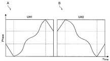
図7は、図6に示す本発明の実施形態に係る送信信号における位相変化の一例を示す説明図である。図7に示すAは、図6のTx1で示される第1の送信信号における位相変化の一例を示しており、図7に示すBは、図6のTx2で示される第2の送信信号における位相変化の一例を示している。 FIG. 7 is an explanatory diagram showing an example of a phase change in the transmission signal according to the embodiment of the present invention shown in FIG. 7 shows an example of a phase change in the first transmission signal indicated by Tx1 in FIG. 6, and B shown in FIG. 7 indicates a phase in the second transmission signal indicated by Tx2 in FIG. An example of the change is shown.
例えば図6を参照して示したように、位相回転方向を一定にした4シンボル単位でフレーム構成を行うと、第1の送信信号におけるフレーム内のビットの位相変化は、図7のAで表され、また、第2の送信信号におけるフレーム内のビットの位相変化は、図7のBで表される。 For example, as shown with reference to FIG. 6, when the frame configuration is performed in units of 4 symbols with a constant phase rotation direction, the phase change of the bits in the frame in the first transmission signal is represented by A in FIG. In addition, the phase change of the bits in the frame in the second transmission signal is represented by B in FIG.
よって、本発明の実施形態に係るユニークワードの前後に反転されたデータが付加されることによって、本発明の実施形態に係る第2の通信装置では、ユニークワードそれぞれの先頭シンボルをより容易に検出することが可能となる。 Therefore, by adding inverted data before and after the unique word according to the embodiment of the present invention, the second communication device according to the embodiment of the present invention more easily detects the first symbol of each unique word. It becomes possible to do.
より具体的には、例えば図6に示すように、第1ユニークワードおよび第2ユニークワードそれぞれの前後に反転されたデータが付加される場合には、本発明の実施形態に係る第1送信信号と本発明の実施形態に係る第2送信信号との位相の変化の仕方が変わる。よって、例えば、第1ユニークワードおよび第2ユニークワードそれぞれの前後に反転されたデータが付加されることによって、本発明の実施形態に係る第2の通信装置では、第1ユニークワードおよび第2ユニークワードそれぞれの先頭シンボルをより容易に検出することができる。 More specifically, for example, as shown in FIG. 6, when inverted data is added before and after the first unique word and the second unique word, the first transmission signal according to the embodiment of the present invention. And how the phase of the second transmission signal according to the embodiment of the present invention changes. Therefore, for example, by adding inverted data before and after the first unique word and the second unique word, in the second communication device according to the embodiment of the present invention, the first unique word and the second unique word The leading symbol of each word can be detected more easily.
上記のように、本発明の実施形態に係る第1の通信装置は、本発明の実施形態に係るユニークワードの前後に、位相の回転方向がユニークワードの位相の回転方向に対して反転されたデータを付加する。 As described above, in the first communication device according to the embodiment of the present invention, the rotation direction of the phase is reversed with respect to the rotation direction of the phase of the unique word before and after the unique word according to the embodiment of the present invention. Append data.
しかしながら、実際には、位相がユニークワードの位相の回転方向と逆方向に回転するように、ビットが割り当てられたデータを付加するだけでは、例えば図7に示すような波形を実現させることはできない。具体的には、位相の変化量を、例えば−180[度]〜180[度]まで回転させることができない。 However, in practice, for example, a waveform as shown in FIG. 7 cannot be realized only by adding data to which bits are assigned so that the phase rotates in the direction opposite to the rotation direction of the phase of the unique word. . Specifically, the amount of phase change cannot be rotated, for example, from −180 [degrees] to 180 [degrees].
図8は、本発明の実施形態に係るユニークワードの前後へのデータの付加の一例を説明するための説明図であり、ビット回転方向が変えられたときの位相変化の一例を示している。ここで、図8は、ビットが、“00”、“10”、“11”、“01”、“11”、“10”の6シンボルで繰り返される場合を示している。 FIG. 8 is an explanatory diagram for explaining an example of adding data before and after the unique word according to the embodiment of the present invention, and shows an example of a phase change when the bit rotation direction is changed. Here, FIG. 8 shows a case where the bits are repeated with 6 symbols of “00”, “10”, “11”, “01”, “11”, “10”.
例えば、“00”、“10”、“11”、“01”という位相回転方向が反時計回りのビットで表されるユニークデータは、フィルタ処理が行われない場合、理想的には、「135[度]、45[度]、−45[度]、−135[度]」で位相が遷移する。ここで、上記ユニークデータの位相の回転方向に対して位相の回転方向を反転させるためには、例えば、“11”、“10”、“00”、“10”というデータが付加されればよい。 For example, unique data represented by bits whose phase rotation direction is “00”, “10”, “11”, “01” in the counterclockwise direction is ideally “135” when the filtering process is not performed. [Degree], 45 [degree], −45 [degree], −135 [degree] ”. Here, in order to reverse the rotation direction of the phase with respect to the rotation direction of the phase of the unique data, for example, data “11”, “10”, “00”, “10” may be added. .
上記“11”、“10”、“00”、“10”というデータが付加された場合、位相は、「−45[度]、45[度]、135[度]、45[度]」で遷移する。ここで、フィルタ処理が行われた場合には、位相の変化量は、例えば図8に示すように、−120[度]〜120[度]となる。 When the data “11”, “10”, “00”, and “10” are added, the phases are “−45 [degree], 45 [degree], 135 [degree], and 45 [degree]”. Transition. Here, when filter processing is performed, the amount of change in phase is, for example, −120 [degrees] to 120 [degrees] as illustrated in FIG. 8.
よって、位相がユニークワードの位相の回転方向と逆方向に回転するように、ビットが割り当てられたデータを付加するだけでは、位相の変化量を、例えば−180[度]〜180[度]まで回転させることができないことから、例えば図7に示すような波形を実現させることはできない。 Therefore, only by adding data to which bits are assigned so that the phase rotates in the direction opposite to the rotation direction of the unique word phase, the amount of phase change can be set to, for example, −180 [degrees] to 180 [degrees]. Since it cannot be rotated, for example, a waveform as shown in FIG. 7 cannot be realized.
ここで、位相の変化量(位相の回転範囲)をより大きくする一の方法としては、例えば、“00”、“10”、“11”、“01”という位相回転方向が反時計回りのビットで表されるユニークデータに対して、“00”、“01”、“11”、“10”というデータを付加することが考えられる。 Here, as one method of increasing the phase change amount (phase rotation range), for example, a bit whose phase rotation direction is “00”, “10”, “11”, “01” is counterclockwise. It is conceivable to add data “00”, “01”, “11”, and “10” to the unique data represented by
上記のように、“00”、“10”、“11”、“01”で表されるユニークデータに対して、“00”、“01”、“11”、“10”というデータが付加される場合には、位相は、「135[度]、45[度]、−45[度]、−135[度]、135[度]、−135[度]、−45[度]、135[度]」で遷移する。よって、位相の変化量は、より大きくなる。しかしながら、“00”、“10”、“11”、“01”で表されるユニークデータに対して、“00”、“01”、“11”、“10”というデータが付加される場合には、位相の不連続が生じる。 As described above, data “00”, “01”, “11”, “10” is added to the unique data represented by “00”, “10”, “11”, “01”. In this case, the phase is “135 [degree], 45 [degree], −45 [degree], −135 [degree], 135 [degree], −135 [degree], −45 [degree], 135 [ [Degree]]. Therefore, the amount of phase change becomes larger. However, when data “00”, “01”, “11”, “10” is added to the unique data represented by “00”, “10”, “11”, “01”. Causes a phase discontinuity.
図9は、本発明の実施形態に係るユニークワードの前後へのデータの付加の一例を説明するための説明図である。ここで、図9は、“00”、“10”、“11”、“01”で表されるユニークデータに対して、“00”、“01”、“11”、“10”というデータが付加される場合における位相変化の一例を示している。 FIG. 9 is an explanatory diagram for explaining an example of adding data before and after the unique word according to the embodiment of the present invention. Here, FIG. 9 shows that the data “00”, “01”, “11”, “10” is different from the unique data represented by “00”, “10”, “11”, “01”. An example of a phase change when added is shown.
例えば図9に示すように、“00”、“10”、“11”、“01”で表されるユニークデータに対して、“00”、“01”、“11”、“10”というデータが付加される場合には、位相の不連続が生じていることが分かる。よって、上記位相の変化量(位相の回転範囲)をより大きくする一の方法を用いることは、望ましくない。 For example, as shown in FIG. 9, the data “00”, “01”, “11”, “10” is compared with the unique data represented by “00”, “10”, “11”, “01”. Is added, it can be seen that a phase discontinuity has occurred. Therefore, it is not desirable to use one method for increasing the amount of phase change (phase rotation range).
そこで、本発明の実施形態に係る第1の通信装置は、“ユニークワードの前後に反転されたデータが付加されたユニークワード”を、例えば下記の(a)、(b)により生成する。
(a)2周期分の位相回転用の波形の信号を用いる
(b)上記2周期分のうち、位相回転の1周期分をユニークワードとし、ユニークワードに該当する1周期分の前後の1周期の半分の区間の位相を反転させるTherefore, the first communication device according to the embodiment of the present invention generates “a unique word with inverted data added before and after a unique word” by, for example, the following (a) and (b).
(A) Use a waveform signal for phase rotation for two cycles. (B) Among the two cycles, one cycle of phase rotation is a unique word, and one cycle before and after one cycle corresponding to the unique word. Invert the phase of half the interval
図10は、本発明の実施形態に係るユニークワードの前後へのデータの付加の一例を説明するための説明図である。図10は、例えば図6に示す第2ユニークワード(図6に示すUW2)の前後に反転されたデータを付加する場合を示している。図10に示すAは、“ユニークワードの前後に反転されたデータが付加されたユニークワード”の生成に用いる位相回転用の波形の一例を示している。また、図10に示すBは、“ユニークワードの前後に反転されたデータが付加されたユニークワード”の位相変化の一例を示している。図10のA、Bに示す区間Aが、上記“2周期分の位相回転用の波形”に該当する。また、図10のA、Bに示す区間Bおよび区間Cが、上記“ユニークワードに該当する1周期分の前後の1周期の半分の区間”に該当する。 FIG. 10 is an explanatory diagram for explaining an example of addition of data before and after the unique word according to the embodiment of the present invention. FIG. 10 shows a case where inverted data is added before and after the second unique word (UW2 shown in FIG. 6) shown in FIG. 6, for example. A shown in FIG. 10 shows an example of a waveform for phase rotation used to generate “a unique word with inverted data added before and after a unique word”. Further, B shown in FIG. 10 shows an example of the phase change of “unique word with inverted data added before and after the unique word”. A section A shown in FIGS. 10A and 10B corresponds to the “waveform for phase rotation for two periods”. Further, the section B and the section C shown in A and B of FIG. 10 correspond to the above-described “half section of one cycle before and after one cycle corresponding to the unique word”.
本発明の実施形態に係る第1の通信装置は、例えば図10のAの区間Aに示すように、2周期分の位相回転用の波形の信号を用いる(上記(a)に該当)。つまり、本発明の実施形態に係る“反転されたデータが付加されたユニークワード”は、位相回転の2周期分に該当する。 The first communication apparatus according to the embodiment of the present invention uses a signal having a waveform for phase rotation for two cycles (corresponding to the above (a)), for example, as shown in a section A of FIG. In other words, the “unique word with inverted data added” according to the embodiment of the present invention corresponds to two periods of phase rotation.
そして、本発明の実施形態に係る第1の通信装置は、例えば、図10のAの区間Bおよび区間Cに対応する信号に対して複素共役をかけることによって、図10のAの区間Bおよび区間Cに対応する信号の位相を反転させる(上記(b)に該当)。よって、ユニークワードの前後に付加される反転されたデータ(図10のAの区間Bおよび区間Cそれぞれの信号に対応するデータ)は、ユニークワードに該当する1周期分の前後の1周期の半分の区間の位相の回転方向が、反転されたデータとなる。 The first communication device according to the embodiment of the present invention, for example, applies a complex conjugate to the signals corresponding to the sections B and C in A in FIG. The phase of the signal corresponding to the section C is inverted (corresponding to (b) above). Therefore, the inverted data added before and after the unique word (data corresponding to the signals in the sections B and C in FIG. 10A) is half of one period before and after one period corresponding to the unique word. The rotation direction of the phase of the section is inverted data.
本発明の実施形態に係る第1の通信装置は、例えば上記のように、上記(a)、(b)によって、“ユニークワードの前後に反転されたデータが付加されたユニークワード”を生成する。なお、図10では、例えば図6に示す第2ユニークワード(図6に示すUW2)の前後に反転されたデータを付加する場合を例に挙げたが、例えば図6に示す第1ユニークワード(図6に示すUW1)の前後に反転されたデータを付加する場合についても、同様である。 The first communication device according to the embodiment of the present invention generates, for example, as described above, “a unique word in which inverted data is added before and after a unique word” by (a) and (b) above. . In FIG. 10, for example, the case where inverted data is added before and after the second unique word (UW2 shown in FIG. 6) shown in FIG. 6, for example, the first unique word (shown in FIG. The same applies to the case where inverted data is added before and after UW1) shown in FIG.
例えば上記のように、本発明の実施形態に係る第1の通信装置が、“ユニークワードの前後に反転されたデータが付加されたユニークワード”を生成することによって、ユニークワード区間の位相変化量を大きくすることができる。よって、後述するように、本発明の実施形態に係る第2の通信装置では、ユニークワードを用いて受信信号に含まれる送信信号の種別をより正確に判別することが可能となるので、本発明の実施形態に係る第2の通信装置におけるキャリア同期の推定精度を向上させることができる。 For example, as described above, the first communication device according to the embodiment of the present invention generates the “unique word with the inverted data before and after the unique word” to thereby generate the phase change amount of the unique word section. Can be increased. Therefore, as described later, in the second communication device according to the embodiment of the present invention, it is possible to more accurately determine the type of transmission signal included in the received signal using the unique word. The accuracy of carrier synchronization estimation in the second communication apparatus according to the embodiment can be improved.
図11は、本発明の実施形態に係るユニークワードの前後に反転されたデータが付加されたユニークワードが用いられることによる効果の一例を説明するための説明図である。図11に示すAは、例えば、図6に示す第1ユニークワード(図6に示すUW1)の前後に反転されたデータの位相変化と、図6に示す第2ユニークワード(図6に示すUW2)の前後に反転されたデータの位相変化との一例を示している。また、図11に示すBは、図11のAに示す第2ユニークワード(図11に示すUW2)のサンプル番号間の位相変化を示している(4倍オーバーサンプル)。 FIG. 11 is an explanatory diagram for explaining an example of an effect obtained by using a unique word to which inverted data is added before and after the unique word according to the embodiment of the present invention. 11 shows, for example, the phase change of the data inverted before and after the first unique word (UW1 shown in FIG. 6) shown in FIG. 6 and the second unique word (UW2 shown in FIG. 6). ) Shows an example of the phase change of the data inverted before and after. Further, B shown in FIG. 11 indicates a phase change between the sample numbers of the second unique word (UW2 shown in FIG. 11) shown in A of FIG. 11 (four times oversample).
例えば図11のBに示すように、ユニークワードの位相変化は直線とはならず、ユニークワードの位相変化には、10[度]〜50[度]までの範囲がある。そのため、サンプル数が少ないときに、ユニークワードのみを用いて受信信号に含まれる送信信号の種別を判別する場合には、受信信号に含まれる送信信号の種別を正確に判別することができないことが起こりうる。 For example, as shown in FIG. 11B, the phase change of the unique word is not a straight line, and the phase change of the unique word has a range from 10 [deg.] To 50 [deg.]. Therefore, when the type of transmission signal included in the reception signal is determined using only the unique word when the number of samples is small, the type of transmission signal included in the reception signal may not be accurately determined. It can happen.
これに対して、本発明の実施形態に係る第1の通信装置が、“ユニークワードの前後に反転されたデータが付加されたユニークワード”を生成することによって、ユニークワード区間の位相変化量を大きくすることが可能であるので、本発明の実施形態に係る第2の通信装置は、例えば、第1ユニークワードおよび第2ユニークワードそれぞれの先頭のシンボルと最後のシンボルとをより容易に検出することができる。したがって、本発明の実施形態に係る第1の通信装置が、“ユニークワードの前後に反転されたデータが付加されたユニークワード”を生成することによって、本発明の実施形態に係る第2の通信装置は、ユニークワードを用いて受信信号に含まれる送信信号の種別をより正確に判別することができる。 On the other hand, the first communication device according to the embodiment of the present invention generates the “unique word with the inverted data added before and after the unique word”, thereby reducing the phase change amount of the unique word section. Since the size can be increased, the second communication apparatus according to the embodiment of the present invention more easily detects, for example, the first symbol and the last symbol of each of the first unique word and the second unique word. be able to. Therefore, the first communication device according to the embodiment of the present invention generates the “unique word with the inverted data before and after the unique word”, thereby generating the second communication according to the embodiment of the present invention. The apparatus can more accurately determine the type of transmission signal included in the reception signal using the unique word.
上記では、本発明の実施形態に係る送信信号のデータフォーマットが、図6に示すデータフォーマットである例を挙げて説明したが、本発明の実施形態に係る送信信号のデータフォーマットは、図6に示す例に限られない。 In the above, an example in which the data format of the transmission signal according to the embodiment of the present invention is the data format illustrated in FIG. 6 has been described, but the data format of the transmission signal according to the embodiment of the present invention is illustrated in FIG. It is not restricted to the example shown.
例えば、本発明の実施形態に係る第1送信信号、本発明の実施形態に係る第2送信信号では、第1ユニークワードおよび第2ユニークワードそれぞれの前後に反転されたデータが付加されていなくてもよい。第1ユニークワードおよび第2ユニークワードそれぞれの前後に反転されたデータが付加されていない場合であっても、例えばユニークワードのサンプル数(オーバーサンプル数)が十分に多いときには、本発明の実施形態に係る第2の通信装置では、受信信号から、本発明の実施形態に係る第1送信信号または本発明の実施形態に係る第2送信信号を検出することは、可能である。 For example, in the first transmission signal according to the embodiment of the present invention and the second transmission signal according to the embodiment of the present invention, the inverted data before and after the first unique word and the second unique word are not added. Also good. Even if the inverted data is not added before and after each of the first unique word and the second unique word, for example, when the number of samples (oversample number) of the unique word is sufficiently large, the embodiment of the present invention In the second communication apparatus according to the above, it is possible to detect the first transmission signal according to the embodiment of the present invention or the second transmission signal according to the embodiment of the present invention from the received signal.
また、図6では、本発明の実施形態に係る第1の通信装置が、第1の送信アンテナと第2の送信アンテナとの2つの送信アンテナを備える場合において送信される送信信号のデータフォーマットの一例を示したが、上述したように、本発明の実施形態に係る第1の通信装置が備える送信アンテナの数は、2つに限られない。 In FIG. 6, the data format of the transmission signal transmitted when the first communication apparatus according to the embodiment of the present invention includes two transmission antennas, ie, the first transmission antenna and the second transmission antenna. Although an example was shown, as described above, the number of transmission antennas included in the first communication device according to the embodiment of the present invention is not limited to two.
[2]本発明の実施形態に係る第2の通信装置(受信側の通信装置)における、本発明の実施形態に係るチャネル推定方法に係る処理
次に、本発明の実施形態に係る第2の通信装置における、本発明の実施形態に係るチャネル推定方法に係る処理について説明する。以下では、本発明の実施形態に係る第2の通信装置が、第1の送信アンテナと第2の送信アンテナとの2つの送信アンテナを備える第1の通信装置から送信される、第1送信信号または第2送信信号が含まれうる受信信号を処理する場合を主に例に挙げて、第2の通信装置における、本発明の実施形態に係るチャネル推定方法に係る処理について説明する。[2] Processing related to the channel estimation method according to the embodiment of the present invention in the second communication device (reception-side communication device) according to the embodiment of the present invention Next, the second communication apparatus according to the embodiment of the present invention Processing related to the channel estimation method according to the embodiment of the present invention in the communication apparatus will be described. In the following, the first transmission signal transmitted from the first communication apparatus provided with the two transmission antennas of the first transmission antenna and the second transmission antenna is transmitted by the second communication apparatus according to the embodiment of the present invention. Or the process which concerns on the channel estimation method which concerns on embodiment of this invention in a 2nd communication apparatus is mainly mentioned as an example mainly when the received signal which may contain a 2nd transmission signal is demonstrated.
本発明の実施形態に係る第2の通信装置は、例えば図6に示すような、ユニークワードを含む送信信号が含まれうる受信信号から、ユニークワードを含む送信信号を検出することによって、フレーム同期を図る。また、本発明の実施形態に係る第2の通信装置は、ユニークワードの位相回転量などに基づいて検出された送信信号の位相を補正することによって、キャリア同期、およびタイミング同期を図る。 The second communication apparatus according to the embodiment of the present invention detects frame transmission by detecting a transmission signal including a unique word from a reception signal that can include a transmission signal including a unique word, for example, as illustrated in FIG. Plan. The second communication apparatus according to the embodiment of the present invention achieves carrier synchronization and timing synchronization by correcting the phase of the transmission signal detected based on the phase rotation amount of the unique word.
例えば上記のように、本発明の実施形態に係る第2の通信装置は、フレーム同期、キャリア同期、およびタイミング同期を図る。よって、本発明の実施形態に係る第2の通信装置は、例えば数式2と同様の原理によって、チャネルをより正確に推定することができる。なお、本発明の実施形態に係る第2の通信装置における、本発明の実施形態に係るチャネル推定方法に係る処理の具体例については、後述する。 For example, as described above, the second communication device according to the embodiment of the present invention achieves frame synchronization, carrier synchronization, and timing synchronization. Therefore, the second communication apparatus according to the embodiment of the present invention can estimate the channel more accurately, for example, based on the same principle as
本発明の実施形態に係るチャネル推定方法が用いられる場合には、本発明の実施形態に係る第1の通信装置(送信側の通信装置)、および本発明の実施形態に係る第2の通信装置(受信側の通信装置)それぞれにおいて、上記のような処理が行われる。 When the channel estimation method according to the embodiment of the present invention is used, the first communication apparatus (transmission-side communication apparatus) according to the embodiment of the present invention and the second communication apparatus according to the embodiment of the present invention The above processing is performed in each (receiving-side communication device).
ここで、本発明の実施形態に係る第1の通信装置と本発明の実施形態に係る第2の通信装置としては、例えば、別体の通信装置が挙げられる。本発明の実施形態に係る第1の通信装置と本発明の実施形態に係る第2の通信装置とが、別体の通信装置である場合には、本発明の実施形態に係る第1の通信装置と本発明の実施形態に係る第2の通信装置とを有する通信システムによって、本発明の実施形態に係るチャネル推定方法が実現される。 Here, examples of the first communication device according to the embodiment of the present invention and the second communication device according to the embodiment of the present invention include separate communication devices. When the first communication device according to the embodiment of the present invention and the second communication device according to the embodiment of the present invention are separate communication devices, the first communication according to the embodiment of the present invention A channel estimation method according to the embodiment of the present invention is realized by a communication system including the apparatus and the second communication device according to the embodiment of the present invention.
なお、本発明の実施形態に係るチャネル推定方法は、通信システムによってされることに限られない。例えば、本発明の実施形態に係る第1の通信装置と本発明の実施形態に係る第2の通信装置とは、1つの通信装置であってもよい。つまり、本発明の実施形態に係る通信装置は、本発明の実施形態に係る第1の通信装置の機能と、本発明の実施形態に係る第2の通信装置との双方を有していてもよい。 Note that the channel estimation method according to the embodiment of the present invention is not limited to being performed by a communication system. For example, the first communication device according to the embodiment of the present invention and the second communication device according to the embodiment of the present invention may be one communication device. In other words, the communication device according to the embodiment of the present invention has both the function of the first communication device according to the embodiment of the present invention and the second communication device according to the embodiment of the present invention. Good.
以下、本発明の実施形態に係る第1の通信装置の構成と、本発明の実施形態に係る第2の通信装置との構成について、より具体的に説明する。また、以下では、本発明の実施形態に係る第1の通信装置と本発明の実施形態に係る第2の通信装置とが、別体の通信装置である場合を主に例に挙げて、本発明の実施形態に係る第1の通信装置の構成および本発明の実施形態に係る第2の通信装置との構成それぞれについて説明する。 Hereinafter, the configuration of the first communication device according to the embodiment of the present invention and the configuration of the second communication device according to the embodiment of the present invention will be described more specifically. In the following description, the first communication device according to the embodiment of the present invention and the second communication device according to the embodiment of the present invention are mainly examples of the case where they are separate communication devices. Each of the configuration of the first communication device according to the embodiment of the invention and the configuration of the second communication device according to the embodiment of the present invention will be described.
また、以下では、本発明の実施形態に係る第1の通信装置が、第1の送信アンテナと第2の送信アンテナとの2つの送信アンテナを備える場合を例に挙げて、本発明の実施形態に係る第1の通信装置の構成の一例について説明する。また、以下では、本発明の実施形態に係る第2の通信装置が、第1の送信アンテナと第2の送信アンテナとの2つの送信アンテナを備える第1の通信装置から送信される、第1送信信号または第2送信信号が含まれうる受信信号を処理する場合を例に挙げて、本発明の実施形態に係る第2の通信装置の構成の一例について説明する。 In the following description, the first communication apparatus according to the embodiment of the present invention is provided with two transmission antennas, ie, a first transmission antenna and a second transmission antenna, as an example. An example of the configuration of the first communication apparatus according to the above will be described. In the following description, the second communication device according to the embodiment of the present invention is transmitted from the first communication device including two transmission antennas, ie, a first transmission antenna and a second transmission antenna. An example of the configuration of the second communication apparatus according to the embodiment of the present invention will be described by taking as an example the case of processing a reception signal that can include a transmission signal or a second transmission signal.
(本発明の実施形態に係る第1の通信装置:送信側の通信装置)
図12A、図12Bは、本発明の実施形態に係る第1の通信装置100の構成の一例を示すブロック図である。(First communication apparatus according to an embodiment of the present invention: a communication apparatus on the transmission side)
12A and 12B are block diagrams illustrating an example of a configuration of the
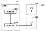
第1の通信装置100は、例えば、第1の送信アンテナ102Aと、第2の送信アンテナ102Bと、送信部104とを備える。 The
また、第1の通信装置100は、例えば、制御部(図示せず)や、ROM(Read Only Memory。図示せず)、RAM(Random Access Memory。図示せず)などを備えていてもよい。第1の通信装置100は、例えば、データの伝送路としてのバスにより上記各構成要素間を接続する。 The
ここで、制御部(図示せず)は、例えば、CPU(Central Processing Unit)や各種処理回路などで構成され、第1の通信装置100全体を制御する。また、制御部(図示せず)は、例えば、送信部104の役目を果たしてもよい。なお、送信部104は、専用の(または汎用の)処理回路で構成されていてもよいことは、言うまでもない。 Here, the control unit (not shown) includes, for example, a CPU (Central Processing Unit), various processing circuits, and the like, and controls the entire
第1の送信アンテナ102Aは、第1の通信装置100が備える第1の通信アンテナであり、第1の送信アンテナ102Aからは、送信部104から伝達される第1送信信号が送信される。 102 A of 1st transmission antennas are the 1st communication antenna with which the
第2の送信アンテナ102Bは、第1の通信装置100が備える第2の通信アンテナであり、第2の送信アンテナ102Bからは、送信部104から伝達される第2送信信号が送信される。 The
送信部104は、例えば図2に示すように、第1送信信号と第2送信信号とを切り替えて送信アンテナから送信させる。 For example, as illustrated in FIG. 2, the
ここで、送信部104は、例えば図12Aに示すように、1つの送信回路によって第1送信信号と第2送信信号とを切り替えて対応する送信アンテナから送信させるが、送信部104の構成は、上記に限られない。例えば、送信部104は、図12Bに示すように、第1の送信アンテナ102Aに対応する第1送信回路106Aと、第2の送信アンテナ102Bに対応する第2送信回路106Bとを備え、第1送信回路106Aと第2送信回路106Bとが連携することによって、第1送信信号と第2送信信号とを対応する送信アンテナから切り替えて送信させてもよい。 Here, as illustrated in FIG. 12A, for example, the
第1の通信装置100は、例えば、図12Aや図12Bに示す構成によって、例えば図2に示すように、第1の送信アンテナから第1送信信号を送信し、第2の送信アンテナから第2送信信号を切り替えて送信する。 The
なお、本発明の実施形態に係る第1の通信装置の構成は、図12A、図12Bに示す構成に限られない。 Note that the configuration of the first communication apparatus according to the embodiment of the present invention is not limited to the configurations shown in FIGS. 12A and 12B.
例えば、本発明の実施形態に係る第1の通信装置は、3つ以上の送信アンテナを備えていてもよい。3つ以上の送信アンテナを備える場合、本発明の実施形態に係る第1の通信装置(より具体的には、例えば第1の通信装置が備える送信部)は、例えば、3つ以上の送信アンテナのうちのある送信アンテナから第1送信信号を送信し、残りの送信アンテナのうちの一の送信アンテナから第2送信信号を切り替えて送信する。 For example, the first communication device according to the embodiment of the present invention may include three or more transmission antennas. When three or more transmission antennas are provided, the first communication device according to the embodiment of the present invention (more specifically, for example, the transmission unit included in the first communication device) is, for example, three or more transmission antennas. The first transmission signal is transmitted from one of the transmission antennas, and the second transmission signal is switched and transmitted from one of the remaining transmission antennas.
また、3つ以上の送信アンテナを備える場合、本発明の実施形態に係る第1の通信装置(より具体的には、例えば第1の通信装置が備える送信部)は、例えば、ユニークワードの系列を変えることによって、各送信アンテナから対応するユニークワードを含む送信信号を切り替えて送信することも可能である。ユニークワードの系列の変え方としては、例えば、ユニークワードの位相回転方向を切り替えること(例えば、ユニークワードが8シンボルで構成される場合において、前半の4シンボルと後半の4シンボルで位相回転方向を異ならせることなど)などが挙げられる。 In addition, when three or more transmission antennas are provided, the first communication device according to the embodiment of the present invention (more specifically, for example, the transmission unit included in the first communication device) is, for example, a sequence of unique words. By changing the transmission signal, it is also possible to switch and transmit the transmission signal including the corresponding unique word from each transmission antenna. As a method of changing the sequence of unique words, for example, the phase rotation direction of the unique word is switched (for example, when the unique word consists of 8 symbols, the phase rotation direction is changed between the first 4 symbols and the latter 4 symbols. Etc.).
また、本発明の実施形態に係る第1の通信装置は、例えば、後述する本発明の実施形態に係る第2の通信装置が備える構成をさらに備えていてもよい。本発明の実施形態に係る第1の通信装置が後述する本発明の実施形態に係る第2の通信装置が備える構成をさらに備える場合には、本発明の実施形態に係る第1の通信装置は、送信側の通信装置および受信側の通信装置双方の機能を有することとなる。 Moreover, the 1st communication apparatus which concerns on embodiment of this invention may further be provided with the structure with which the 2nd communication apparatus which concerns on embodiment of this invention mentioned later is provided, for example. When the first communication apparatus according to the embodiment of the present invention further includes a configuration included in the second communication apparatus according to the embodiment of the present invention described later, the first communication apparatus according to the embodiment of the present invention is The functions of both the communication device on the transmission side and the communication device on the reception side are provided.
例えば上記のように、本発明の実施形態に係る第1の通信装置が、送信側の通信装置および受信側の通信装置双方の機能を有する場合であっても、本発明の実施形態に係る第1の通信装置は、後述する本発明の実施形態に係る第2の通信装置と同様にチャネルを推定することが可能である。よって、本発明の実施形態に係る第1の通信装置が、送信側の通信装置および受信側の通信装置双方の機能を有する場合には、本発明の実施形態に係る第1の通信装置は、MIMOにおけるチャネル推定の精度を向上させることができる。 For example, as described above, even if the first communication device according to the embodiment of the present invention has the functions of both the transmission-side communication device and the reception-side communication device, the first communication device according to the embodiment of the present invention. The first communication apparatus can estimate the channel in the same manner as the second communication apparatus according to an embodiment of the present invention described later. Therefore, when the first communication device according to the embodiment of the present invention has the functions of both the transmission-side communication device and the reception-side communication device, the first communication device according to the embodiment of the present invention is The accuracy of channel estimation in MIMO can be improved.
また、本発明の実施形態に係る第1の通信装置は、例えば、送信アンテナ102Aと、102Bを備えない構成であってもよい。送信アンテナ102Aと、102Bを備えない構成であっても、本発明の実施形態に係る第1の通信装置は、例えば、“送信アンテナ102Aと、102Bに該当する外部の通信に係るデバイス”を介して、ユニークワードを含む送信信号を切り替えて送信させることが可能である。 In addition, the first communication device according to the embodiment of the present invention may be configured not to include, for example, the
(本発明の実施形態に係る第2の通信装置:受信側の通信装置)
図13は、本発明の実施形態に係る第2の通信装置200の構成の一例を示すブロック図である。(Second communication apparatus according to an embodiment of the present invention: a communication apparatus on the receiving side)
FIG. 13 is a block diagram showing an example of the configuration of the
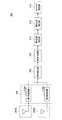
第2の通信装置200は、例えば、第1の受信アンテナ202Aと、第2の受信アンテナ202Bと、受信部204と、信号検出部206と、信号判別部208と、第1位相補正部210と、第2位相補正部212と、チャネル推定部214とを備える。 The
また、第2の通信装置200は、例えば、制御部(図示せず)や、ROM(図示せず)、RAM(図示せず)などを備えていてもよい。第2の通信装置200は、例えば、データの伝送路としてのバスにより上記各構成要素間を接続する。 The
ここで、制御部(図示せず)は、例えば、CPUや各種処理回路などで構成され、第2の通信装置200全体を制御する。また、制御部(図示せず)は、例えば、受信部204、信号検出部206、信号判別部208、第1位相補正部210、第2位相補正部212、およびチャネル推定部214のうちの1または2以上の役目を果たしてもよい。なお、受信部204、信号検出部206、信号判別部208、第1位相補正部210、第2位相補正部212、およびチャネル推定部214それぞれは、各部の機能を実現することが可能な専用の(または汎用の)処理回路で構成されていてもよいことは、言うまでもない。 Here, the control unit (not shown) includes, for example, a CPU and various processing circuits, and controls the entire
第1の受信アンテナ202Aは、第2の通信装置200が備える第1の通信アンテナであり、本発明の実施形態に係る第1の通信装置から送信される送信信号が含まれるうる信号を、受信する。例えば本発明の実施形態に係る第1の通信装置が、図12Aや図12Bに示す構成である場合、第1の受信アンテナ202Aは、例えば図2に示すような、第1の送信アンテナ102Aから送信される第1送信信号または第2の送信アンテナ102Bから第2送信信号が含まれうる信号を、受信する。 The
第2の受信アンテナ202Bは、第2の通信装置200が備える第2の通信アンテナであり、本発明の実施形態に係る第1の通信装置から送信される送信信号が含まれるうる信号を、受信する。例えば本発明の実施形態に係る第1の通信装置が、図12Aや図12Bに示す構成である場合、第2の受信アンテナ202Bは、例えば図2に示すような、第1の送信アンテナ102Aから送信される第1送信信号または第2の送信アンテナ102Bから第2送信信号が含まれうる信号を、受信する。 The
受信部204は、例えば受信アンテナそれぞれに対応する受信回路を備え、受信アンテナそれぞれが受信した信号を復調する。また、受信部204は、例えば、ロールオフフィルタなどのフィルタを用いてフィルタ処理を行う。例えば図13に示す例では、受信部204は、第1の受信アンテナ202Aが受信した信号を復調する第1受信回路216Aと、第2の受信アンテナ202Bが受信した信号を復調する第2受信回路216Bとを備える。 The receiving
信号検出部206は、フレーム同期を行う役目を果たす。より具体的には、信号検出部206は、例えば、受信信号から切り替えて送信される送信信号の切替区間を検出することによって、送信信号を検出する。例えば図6に示すような第1送信信号と第2送信信号とが本発明の実施形態に係る第1の通信装置から送信される場合には、信号検出部206は、例えば、受信信号から第1送信信号と第2送信信号との切替区間を検出することによって、第1送信信号と第2送信信号とのうちのいずれかの送信信号を検出する。 The
ここで、本発明の実施形態に係る第1の通信装置は、例えば図6に示すように、各送信信号を切り替えて送信する。また、例えば図6に示すように、本発明の実施形態に係る送信信号の切り替えに際しては、切替区間が存在する。なお、本発明の実施形態に係る切替区間は、例えば、本発明の実施形態に係る第1の通信装置が意図的に設ける期間であってもよいし、本発明の実施形態に係る第1送信信号と本発明の実施形態に係る第2送信信号との切り替えに際して生じる期間であってもよい。 Here, the 1st communication apparatus which concerns on embodiment of this invention switches and transmits each transmission signal, for example, as shown in FIG. For example, as shown in FIG. 6, there is a switching section when switching transmission signals according to the embodiment of the present invention. Note that the switching interval according to the embodiment of the present invention may be, for example, a period provided intentionally by the first communication device according to the embodiment of the present invention, or the first transmission according to the embodiment of the present invention. It may be a period generated when switching between the signal and the second transmission signal according to the embodiment of the present invention.
本発明の実施形態に係る切替区間は、本発明の実施形態に係る第1の通信装置から送信信号が送信されない期間であるので、第2の通信装置200が処理する受信信号は、ノイズのみとなる。そこで、第2の通信装置200は、ノイズのみを含む受信信号を検出すること、すなわち、受信信号におけるノイズ区間を検出することによって、受信信号から第1送信信号または第2送信信号を含むデータ区間を検出する。 Since the switching interval according to the embodiment of the present invention is a period during which a transmission signal is not transmitted from the first communication device according to the embodiment of the present invention, the reception signal processed by the
図14は、本発明の実施形態に係る第2の通信装置200におけるフレーム同期に係る処理の一例を説明するための説明図である。ここで、図14は、第2の通信装置200が受信する受信信号の一例を示している。 FIG. 14 is an explanatory diagram for explaining an example of processing related to frame synchronization in the
第2の通信装置200は、受信された受信信号から設定されている時間内における電力の最大値を検出する。ここで、上記設定されている時間としては、例えば、2シンボル分に相当する時間などが挙げられる。 The
また、第2の通信装置200は、検出された最大値から設定されている値を減算した値を、閾値として設定する。ここで、検出された最大値から減算する値は、例えば、第1送信信号と第2送信信号との電力の差分値より大きく設定される。 Further, the
そして、第2の通信装置200は、設定された閾値以下の区間(または、設定された閾値より小さな区間。以下、同様とする。)を、ノイズ区間として判定し、判定されたノイズ区間に続く区間を、送信信号を含む区間であるデータ区間であると判定する。 Then, the
例えば上記のように、送信信号を含むデータ区間を判定することによって、第2の通信装置200は、フレーム位置を特定することが可能となる。したがって、第2の通信装置200が、受信信号から送信信号の切替区間を検出して、送信信号を検出することによって、第2の通信装置200は、フレーム同期を図ることができる。 For example, as described above, the
再度図13を参照して、本発明の実施形態に係る第2の通信装置200の構成の一例について説明する。信号判別部208は、検出された送信信号に含まれるユニークワードの位相回転量によって、検出された送信信号を判別する。信号判別部208は、例えば、検出された送信信号に含まれるユニークワードの位相回転量に基づく検出された送信信号に含まれるユニークワードの位相の変化の仕方の違いによって、検出された送信信号を判別する。ここで、本発明の実施形態に係るユニークワードの位相回転量は、例えば、設定されている基準となる位相の回転方向(例えば、反時計回りや、時計回り)を正として表される。 With reference to FIG. 13 again, an example of the configuration of the
例えば図6に示すような第1送信信号と第2送信信号とが本発明の実施形態に係る第1の通信装置から送信される場合には、信号判別部208は、検出された送信信号に含まれるユニークワードの位相回転量によって、検出された送信信号が、第1送信信号であるかまたは第2送信信号であるかを判別する。 For example, when the first transmission signal and the second transmission signal as shown in FIG. 6 are transmitted from the first communication apparatus according to the embodiment of the present invention, the
また、例えば図12A、図12Bを参照して説明したように、本発明の実施形態に係る第1の通信装置は、第1送信信号と第2送信信号となど、送信アンテナに対応する送信信号を異なる送信アンテナから切り替えて送信する。よって、信号判別部208は、検出された送信信号を判別することによって、例えば、送信信号が送信された送信アンテナを判別することも可能である。例えば、図6に示すような第1送信信号と第2送信信号とが本発明の実施形態に係る第1の通信装置から送信され、ユニークワードと送信アンテナとの対応関係が本発明の実施形態に係る第2の通信装置において既知である場合には、信号判別部208は、検出された送信信号が第1送信信号であるかまたは第2送信信号であるかを判別することによって、送信信号が送信された送信アンテナが、第1の通信アンテナ102Aであるか、または、第2の通信アンテナ102Bであるかを判別することができる。 For example, as described with reference to FIGS. 12A and 12B, the first communication apparatus according to the embodiment of the present invention transmits a transmission signal corresponding to a transmission antenna, such as a first transmission signal and a second transmission signal. Are switched from different transmission antennas and transmitted. Therefore, the
以下、例えば図6に示すような第1送信信号と第2送信信号とが本発明の実施形態に係る第1の通信装置から送信される場合を例に挙げて、信号判別部208における信号判別に係る処理の一例を説明する。 Hereinafter, for example, the signal discrimination in the
信号判別部208は、反転されたデータが付加されたユニークワードにおける位相変化量に基づいて、送信信号に含まれるユニークワードを特定する。そして、信号判別部208は、例えば、検出された送信信号においてユニークワードの前後に付加されている反転されたデータを削除する。 The
より具体的には、信号判別部208は、例えば、位相変化量に基づいて、ユニークワードと反転されたデータとの間において位相の回転方向が異なることによる、位相の変化の仕方の違いを検出することによって、ユニークワードを特定する。そして、信号判別部208は、特定されたユニークワードの前後のデータを削除する。 More specifically, the
ユニークワードの前後に付加されている反転されたデータが削除されると、信号判別部208は、ユニークワードの位相回転量を算出し、算出されたユニークワードの位相回転量によって、検出された送信信号が、第1送信信号であるかまたは第2送信信号であるかを判別する。本発明の実施形態に係る信号判別部208は、位相回転量を算出可能な任意の方法を用いて位相回転量を算出する。 When the inverted data added before and after the unique word is deleted, the
上述したように、例えば、第1ユニークワードと第2ユニークワードとの位相回転方向は逆であることから、第1ユニークワードと第2ユニークワードとにおける位相の増減(位相の変化の仕方)は異なる。また、本発明の実施形態に係るユニークワードの位相回転量は、例えば、設定されている基準となる位相の回転方向(例えば、反時計回りや、時計回り)を正として表される。 As described above, for example, since the phase rotation directions of the first unique word and the second unique word are opposite, the phase increase / decrease (how the phase changes) between the first unique word and the second unique word is Different. In addition, the phase rotation amount of the unique word according to the embodiment of the present invention is expressed with the rotation direction (for example, counterclockwise or clockwise) of the reference phase that is set as positive, for example.
信号判別部208は、例えば、算出された位相回転量が正であれば、検出された送信信号が第1送信信号であると判定し、また、算出した位相回転量が負であれば、検出された送信信号が第2送信信号であると判定する。よって、信号判別部208は、例えば上記のように、算出されたユニークワードの位相回転量によって、検出された送信信号が、第1送信信号であるかまたは第2送信信号であるかを判別することができる。 For example, if the calculated phase rotation amount is positive, the
再度図13を参照して、本発明の実施形態に係る第2の通信装置200の構成の一例について説明する。第1位相補正部210は、キャリア同期を行う役目を果たす。 With reference to FIG. 13 again, an example of the configuration of the
第1位相補正部210は、例えば、判別された送信信号に含まれるユニークワードの位相回転量と、判別された送信信号に対応する基準位相回転量との位相回転差分を算出する。そして、第1位相補正部210は、算出された位相回転差分に基づいて、判別された送信信号の位相を補正することによって、キャリア同期を行う。 For example, the first
以下、例えば図6に示すような第1送信信号と第2送信信号とが本発明の実施形態に係る第1の通信装置から送信される場合を例に挙げて、第1位相補正部210におけるキャリア同期に係る処理の一例を説明する。 Hereinafter, for example, a case where the first transmission signal and the second transmission signal as illustrated in FIG. 6 are transmitted from the first communication device according to the embodiment of the present invention will be described. An example of processing related to carrier synchronization will be described.
理想的には1シンボルあたりπ/2[rad.](90[度])ずつ位相が回転するが、実際には、1シンボルごとに位相オフセットΔθ[rad.]が生じる。つまり、例えば、判別された送信信号に対応する1シンボルごとの基準位相回転量と、実際の1シンボルごとの位相回転量との間には、上記位相オフセットΔθに該当する位相回転差分が存在しうる。 Ideally, π / 2 per symbol [rad. ] (90 [degrees]) in phase, but in practice, the phase offset Δθ [rad. ] Occurs. That is, for example, a phase rotation difference corresponding to the phase offset Δθ exists between the reference phase rotation amount for each symbol corresponding to the determined transmission signal and the actual phase rotation amount for each symbol. sell.
そこで、第1位相補正部210は、例えば、1シンボルごとに生じうる位相オフセットΔθを、例えば下記の数式3により算出する。ここで、数式3に示す“NUW”は、ユニークワードの数を示しており、数式3に示す“NOver”は、オーバーサンプル数を示している。また、数式3に示す“θ(i)”は、時刻iにおける位相[rad.]を示している。数式3に示す“pd(i)”は、i番目(時刻i)のサンプルのユニークワードとi+1番目(時刻i+1)のサンプルのユニークワードとにおける位相差を示している。数式3に示す“pd(i)”の値としては、例えば、図11のBに示すような、サンプル番号間の位相変化の値が挙げられる。Therefore, the first
そして、第1位相補正部210は、算出された位相オフセットΔθを用いて、判別された送信信号の位相を補正する。ここで、第1位相補正部210は、例えば、1シンボルごとに判別された送信信号の位相を補正する。 Then, the first
時刻tの信号をr(t)とすると、補正後の受信信号は、例えば下記の数式4で表される。 Assuming that the signal at time t is r (t), the corrected received signal is expressed, for example, by
r’(t)=r(t)・exp(−j・Δθ・t)
・・・(数式4)r ′ (t) = r (t) · exp (−j · Δθ · t)
... (Formula 4)
なお、第1位相補正部210における処理は、上記に限られない。例えば、第1位相補正部210は、複数シンボルそれぞれに対応する算出された位相オフセットΔθの平均値などを用いて、複数シンボルごとに判別された送信信号の位相を補正することも可能である。 Note that the processing in the first
例えば上記のように、判別された送信信号の位相が補正されることによって、上記位相オフセットΔθに該当する位相回転差分が補正されて、補正後のユニークワードの位相回転量は、理想的なユニークワードの位相回転量に近づく。よって、第1位相補正部210が、判別された送信信号に含まれるユニークワードの位相回転量と判別された送信信号に対応する基準位相回転量との位相回転差分に基づいて判別された送信信号の位相を補正することによって、キャリアオフセットが補償されるので、キャリア同期が図られる。 For example, as described above, by correcting the phase of the determined transmission signal, the phase rotation difference corresponding to the phase offset Δθ is corrected, and the phase rotation amount of the corrected unique word is an ideal unique value. It approaches the amount of phase rotation of the word. Therefore, the transmission signal determined by the first
第2位相補正部212は、タイミング同期を行う役目を果たす。 The second
第2位相補正部212は、第1位相補正部210から伝達される、位相回転差分に基づいて位相が補正された送信信号と、位相の初期値との誤差を補正する。 The second
以下、例えば図6に示すような第1送信信号と第2送信信号とが本発明の実施形態に係る第1の通信装置から送信される場合を例に挙げて、第2位相補正部212における処理の一例を説明する。 Hereinafter, for example, in the case where the first transmission signal and the second transmission signal as illustrated in FIG. 6 are transmitted from the first communication device according to the embodiment of the present invention, in the second
補正後のユニークワードの位相回転量と理想的なユニークワードの位相回転量との間にはタイミング誤差が生じうる。そして、上記タイミング誤差が生じた場合には、位相回転差分に基づいて位相が補正された送信信号の初期位相がずれる。ここで、上記のようなタイミング誤差は、例えば、“本発明の実施形態に係る第1の通信装置が備える送信回路が有するD/Aコンバータ(Digital-to-Analog converter)と、受信部204が備える受信回路が有するA/Dコンバータ(Analog-to-Digital converter)との間のサンプリングレート誤差”や、本発明の実施形態に係る第1の通信装置における送信信号の切り替え時間の誤差などによって生じる。 A timing error may occur between the phase rotation amount of the unique word after correction and the phase rotation amount of the ideal unique word. When the timing error occurs, the initial phase of the transmission signal whose phase is corrected based on the phase rotation difference is shifted. Here, the timing error as described above is, for example, “a digital-to-analog converter (D / A converter) included in the transmission circuit included in the first communication device according to the embodiment of the present invention and the
そこで、第2位相補正部212は、上記のような、位相回転差分に基づいて位相が補正された送信信号と位相の初期値との誤差を補正することによって、タイミングを補償し、タイミング同期を図る。 Therefore, the second
タイミング誤差をTs[rad.]とすると、第2位相補正部212において補正された受信信号は、例えば下記の数式5で表される。 The timing error is expressed as Ts [rad. ], The received signal corrected by the second
r’ ’(t)=r’(t)・exp(−j・Ts)
・・・(数式5)r ′ ′ (t) = r ′ (t) · exp (−j · Ts)
... (Formula 5)
チャネル推定部214は、第2位相補正部212において位相の誤差が補正された判別された送信信号と、既知の信号(本発明の実施形態に係る第1の通信装置および第2の通信装置200において既知の信号)とに基づいて、チャネルを推定する。 The
より具体的には、チャネル推定部214は、例えば、既知信号の先頭(t=tmax)を検出する。そして、チャネル推定部214は、検出された既知信号の先頭を用いて、第2位相補正部212において位相の誤差が補正された判別された送信信号(すなわち第1位相補正部210および第2位相補正部212において位相の誤差が補正された判別された受信信号“r’
’(t)”)に対して、例えば下記の数式6に示す演算を行うことによって、チャネルを推定する。More specifically, the
'(T) ") is estimated, for example, by performing the calculation shown in Equation 6 below.
ここで、数式6に示す “r’’(t)”は、例えば下記の数式7で表すことも可能である。また、数式7に示す“h”は、チャネル応答を示し、数式7に示す“s(t)”は、本発明の実施形態に係る第1の通信装置および第2の通信装置200における既知の信号を示している。また、数式7に示す“n(t)”は、熱雑音を示している。 Here, “r ″ (t)” shown in Expression 6 can also be expressed by Expression 7 below, for example. Further, “h” shown in Equation 7 represents a channel response, and “s (t)” shown in Equation 7 is a known value in the first communication device and the
r’’(t)=h・s(t)+n(t)
・・・(数式7)r ″ (t) = h · s (t) + n (t)
... (Formula 7)
図15は、本発明の実施形態に係る第2の通信装置200におけるチャネル推定の結果の一例を説明するための説明図である。ここで、図15に示すAは、第2の通信装置200において、本発明の実施形態に係るチャネル推定方法に係る処理が行われた結果の一例、すなわち、フレーム同期、キャリア同期、およびタイミング同期が図られた結果の一例を示している。また、図15に示すBは、本発明の実施形態に係るチャネル推定方法に係る処理が行われた結果を説明するための比較例であり、フレーム同期、キャリア同期、およびタイミング同期が図られていない場合の結果の一例を示している。図15では、SNR(Signal-to-Noise Ratio)が30[dB]であり、オーバーサンプル数=4である場合における結果の一例を示している。また、図15に示すAでは、ユニークワードのデータ長を4シンボルとし、ユニークワードの前後に付加される反転されたデータのデータ長をそれぞれ2シンボルとしている。 FIG. 15 is an explanatory diagram for explaining an example of a result of channel estimation in the
また、図15のAに示すh11は、第1の通信装置100の第1の送信アンテナ102Aと、第2の通信装置200の第1の受信アンテナ202Aとの間の伝搬チャネルの推定結果を示している。図15のAに示すh12は、第1の通信装置100の第1の送信アンテナ102Aと、第2の通信装置200の第2の受信アンテナ202Bとの間の伝搬チャネルの推定結果を示している。図15のAに示すh21は、第1の通信装置100の第2の送信アンテナ102Bと、第2の通信装置200の第1の受信アンテナ202Aとの間の伝搬チャネルの推定結果を示している。図15のAに示すh22は、第1の通信装置100の第2の送信アンテナ102Bと、第2の通信装置200の第2の受信アンテナ202Bとの間の伝搬チャネルの推定結果を示している。 In addition, h11 illustrated in FIG. 15A indicates an estimation result of a propagation channel between the
例えば図15のBに示すように、フレーム同期、キャリア同期、およびタイミング同期が図られていない場合には、伝搬チャネルを推定することは困難である。これに対して、本発明の実施形態に係るチャネル推定方法に係る処理が行われた場合には、例えば図15のBに示すように、各伝搬チャネルが、ほぼ固定された場所で推定されていることが分かる。 For example, as shown in FIG. 15B, when frame synchronization, carrier synchronization, and timing synchronization are not achieved, it is difficult to estimate the propagation channel. On the other hand, when the processing according to the channel estimation method according to the embodiment of the present invention is performed, each propagation channel is estimated at a substantially fixed location, for example, as shown in FIG. I understand that
よって、図15に示すように、第2の通信装置200が本発明の実施形態に係るチャネル推定方法に係る処理を行うことによって、チャネルの推定精度を向上させることができる。 Therefore, as shown in FIG. 15, the
第2の通信装置200は、例えば図13に示す構成によって、チャネルを推定する。 The
ここで、第2の通信装置200は、信号検出部206においてフレーム同期を図り、信号判別部208において送信信号(または、送信アンテナ)を判別する。また、第2の通信装置200は、第1位相補正部210においてキャリア同期を図り、第2位相補正部212においてタイミング同期を図る。そして、第2の通信装置200は、チャネル推定部214において、キャリア同期とタイミング同期とが図られた送信信号(受信信号から検出した送信信号)からチャネルを推定する。 Here, in the
したがって、第2の通信装置200は、例えば図13に示す構成によって、例えば図15に示すように、MIMOにおけるチャネル推定の精度を向上させることができる。 Therefore, the
また、第2の通信装置200は、例えば、OFDMを用いずに、OQPSKにより変調されたOQPSK信号など、原点Oを通過する位相遷移が生じない様々な変調方式により変調された信号を処理してチャネル推定を行うことが可能である。よって、第2の通信装置200が用いられることによって、OFDMが用いられる場合よりも通信に係るデバイス(例えば送信機回路など)のコストを低減することができる。 Further, the
さらに、第2の通信装置200は、例えば、OFDMを用いずに、OQPSKにより変調されたOQPSK信号など、原点Oを通過する位相遷移が生じない様々な変調方式により変調された信号を処理してチャネル推定を行うことが可能であるので、OFDM信号のような高速な信号は必要なく、より低速な信号を用いてチャネルを推定することができる。 Furthermore, the
なお、本発明の実施形態に係る第2の通信装置の構成は、図13に示す構成に限られない。 Note that the configuration of the second communication apparatus according to the embodiment of the present invention is not limited to the configuration shown in FIG.
例えば、本発明の実施形態に係る第2の通信装置は、受信アンテナ202A、202B、および/または、受信部204とを備えない構成であってもよい。受信アンテナ202A、202B、および/または、受信部204とを備えない構成であっても、本発明の実施形態に係る第2の通信装置は、例えば、“受信アンテナ202A、202Bに該当する外部の通信に係るデバイスから受信した信号に基づく受信信号”や、“受信アンテナ202A、202Bおよび受信部204に該当する外部の通信に係るデバイスから受信した受信信号”に対して、本発明の実施形態に係るチャネル推定方法に係る処理を行うことが可能である。よって、例えば受信アンテナ202A、202B、および/または、受信部204とを備えない構成であっても、本発明の実施形態に係る第2の通信装置は、MIMOにおけるチャネル推定の精度を向上させることができる。 For example, the second communication device according to the embodiment of the present invention may be configured not to include the
また、本発明の実施形態に係る第2の通信装置は、例えば、上述した本発明の実施形態に係る第1の通信装置が備える構成(例えば図12A、図12Bに示す構成や変形例に係る構成など)をさらに備えていてもよい。本発明の実施形態に係る第2の通信装置が上述した本発明の実施形態に係る第1の通信装置が備える構成をさらに備える場合には、本発明の実施形態に係る第2の通信装置は、送信側の通信装置および受信側の通信装置双方の機能を有することとなる。 In addition, the second communication device according to the embodiment of the present invention includes, for example, a configuration (for example, the configuration illustrated in FIG. 12A and FIG. 12B or a modification thereof) included in the first communication device according to the embodiment of the present invention described above. And the like. When the second communication apparatus according to the embodiment of the present invention further includes the configuration included in the first communication apparatus according to the embodiment of the present invention described above, the second communication apparatus according to the embodiment of the present invention is The functions of both the communication device on the transmission side and the communication device on the reception side are provided.
例えば上記のように、本発明の実施形態に係る第2の通信装置が、送信側の通信装置および受信側の通信装置双方の機能を有する場合であっても、本発明の実施形態に係る第2の通信装置は、例えば図13に示す構成と同様にチャネルを推定することが可能である。よって、本発明の実施形態に係る第2の通信装置が、送信側の通信装置および受信側の通信装置双方の機能を有する場合であっても、本発明の実施形態に係る第2の通信装置は、例えば図13に示す第2の通信装置200と同様の効果を奏することができる。 For example, as described above, even if the second communication device according to the embodiment of the present invention has the functions of both the transmission-side communication device and the reception-side communication device, the second communication device according to the embodiment of the present invention. The
以上、本発明の実施形態として第1の通信装置(送信側の通信装置)を挙げて説明したが、本発明の実施形態は、かかる形態に限られない。本発明の実施形態は、例えば、伝搬チャネル応答変化を利用する電波センサや空間センサ、当該センサを有する様々な装置に適用することができる。 As described above, the first communication apparatus (transmission-side communication apparatus) has been described as an embodiment of the present invention. However, the embodiment of the present invention is not limited to this form. The embodiment of the present invention can be applied to, for example, a radio wave sensor or a spatial sensor that uses a propagation channel response change, and various devices including the sensor.
また、本発明の実施形態として第2の通信装置(受信側の通信装置)を挙げて説明したが、本発明の実施形態は、かかる形態に限られない。本発明の実施形態は、例えば、伝搬チャネル応答変化を利用する電波センサや空間センサ、当該センサを有する様々な装置に適用することができる。また、本発明の実施形態は、上記のようなセンサや装置に組み込むことが可能な、信号処理IC(Integrated Circuit)として実現することも可能である。 In addition, the second communication apparatus (reception-side communication apparatus) has been described as an embodiment of the present invention, but the embodiment of the present invention is not limited to this form. The embodiment of the present invention can be applied to, for example, a radio wave sensor or a spatial sensor that uses a propagation channel response change, and various devices including the sensor. The embodiment of the present invention can also be realized as a signal processing IC (Integrated Circuit) that can be incorporated in the above-described sensor or device.
また、上述したように、本発明の実施形態では、例えば、本発明の実施形態に係る第1の通信装置と本発明の実施形態に係る第2の通信装置とを有する通信システムによって、本発明の実施形態に係るチャネル推定方法を実現してもよいし、本発明の実施形態に係る第1の通信装置の機能と本発明の実施形態に係る第2の通信装置の機能との双方の通信装置の機能を有する1つの通信装置によって、本発明の実施形態に係るチャネル推定方法を実現することも可能である。 Further, as described above, in the embodiment of the present invention, for example, the communication system having the first communication device according to the embodiment of the present invention and the second communication device according to the embodiment of the present invention is used. The channel estimation method according to the embodiment may be realized, and both the function of the first communication device according to the embodiment of the present invention and the function of the second communication device according to the embodiment of the present invention are communicated. It is also possible to realize the channel estimation method according to the embodiment of the present invention by one communication device having the function of the device.
また、上記では、本発明の実施形態に係るチャネル推定方法が、MIMOに適用される例を示したが、本発明の実施形態は、例えば、MISO(Multi-Input Single-Output)に適用することも可能である。 In the above description, the channel estimation method according to the embodiment of the present invention is applied to MIMO. However, the embodiment of the present invention is applied to, for example, MISO (Multi-Input Single-Output). Is also possible.
また、本発明の実施形態に係るチャネル推定方法が用いられることによって、例えば、人や物体の侵入や、生体の呼吸、心臓などの生体の動きで発生する伝搬環境の変動を推定することが可能である。 Further, by using the channel estimation method according to the embodiment of the present invention, for example, it is possible to estimate a change in a propagation environment caused by invasion of a person or an object, respiration of a living body, movement of a living body such as a heart, etc. It is.
(本発明の実施形態に係るプログラム)
コンピュータを、本発明の実施形態に係る第1の通信装置(送信側の通信装置)として機能させるためのプログラム(例えば、図12A、図12Bに示す送信部104として機能させるためのプログラム)が、コンピュータにおいて実行されることによって、複数の送信アンテナそれぞれに対応する、本発明の実施形態に係る送信信号の送信の切り替えが実現される。(Program according to an embodiment of the present invention)
A program for causing a computer to function as the first communication device (transmission-side communication device) according to the embodiment of the present invention (for example, a program for causing the computer to function as the
また、コンピュータを、本発明の実施形態に係る第2の通信装置(受信側の通信装置)として機能させるためのプログラム(例えば、図13に示す信号検出部206、信号判別部208、第1位相補正部210、第2位相補正部212、およびチャネル推定部214として機能させるためのプログラム)が、コンピュータにおいて実行されることによって、例えばMIMOにおけるチャネル推定の精度を向上させることができる。 Further, a program (for example, the
以上、添付図面を参照しながら本発明の好適な実施形態について説明したが、本発明は係る例に限定されないことは言うまでもない。当業者であれば、特許請求の範囲に記載された範疇内において、各種の変更例または修正例に想到し得ることは明らかであり、それらについても当然に本発明の技術的範囲に属するものと了解される。 As mentioned above, although preferred embodiment of this invention was described referring an accompanying drawing, it cannot be overemphasized that this invention is not limited to the example which concerns. It will be apparent to those skilled in the art that various changes and modifications can be made within the scope of the claims, and these are naturally within the technical scope of the present invention. Understood.
例えば、上記では、コンピュータを、本発明の実施形態に係る第1の通信装置(送信側の通信装置)、または、本発明の実施形態に係る第2の通信装置(受信側の通信装置)として機能させるためのプログラム(コンピュータプログラム)が提供されることを示したが、本発明の実施形態は、さらに、上記プログラムをそれぞれ記憶させた記録媒体や、上記プログラムを共に記憶させた記録媒体も併せて提供することができる。 For example, in the above, the computer is used as the first communication device (transmission-side communication device) according to the embodiment of the present invention or the second communication device (reception-side communication device) according to the embodiment of the present invention. Although it has been shown that a program (computer program) for functioning is provided, the embodiment of the present invention further includes a recording medium that stores the program and a recording medium that stores the program together. Can be provided.
100 第1の通信装置
102A、102B 送信アンテナ
104 送信部
106 送信回路
106A 第1送信回路
106B 第2送信回路
200 第2の通信装置
202A、202B 受信アンテナ
204 受信部
206 信号検出部
208 信号判別部
210 第1位相補正部
212 第2位相補正部
214 チャネル推定部
216A 第1受信回路
216B 第2受信回路
DESCRIPTION OF
Claims (6)
Translated fromJapanese前記受信信号から切り替えて送信される前記送信信号の切替区間を検出することによって、前記送信信号を検出する信号検出部と、
検出された送信信号に含まれるユニークワードの位相回転量によって、検出された送信信号を判別する信号判別部と、
判別された送信信号に含まれるユニークワードの位相回転量と、前記判別された送信信号に対応する基準位相回転量との位相回転差分に基づいて、前記判別された送信信号の位相を補正する第1位相補正部と、
前記位相回転差分に基づいて位相が補正された送信信号と位相の初期値との誤差を補正する第2位相補正部と、
位相の誤差が補正された前記判別された送信信号と、既知の信号とに基づいて、チャネルを推定するチャネル推定部と、
を備え、
前記ユニークワードの前後には、位相の回転方向が前記ユニークワードの位相の回転方向に対して反転されたデータが付加され、前記信号判別部は、前記反転されたデータが付加された前記ユニークワードにおける位相変化量に基づいて、前記送信信号に含まれる前記ユニークワードを特定し、
前記反転されたデータが付加された前記ユニークワードは、位相回転の2周期分に該当し、
前記2周期分のうち、前記ユニークワードは、位相回転の1周期分に該当し、前記ユニークワードの前後に付加される前記反転されたデータは、前記ユニークワードに該当する前記1周期分の前後の1周期の半分の区間の位相の回転方向が、反転されたデータであることを特徴とする、通信装置。A communication apparatus for processing a received signal obtained by demodulating a signal received by a receiving antenna, which can include a transmission signal including a unique unique word corresponding to the transmitting antenna, which is transmitted by switching from a plurality of transmitting antennas. And
A signal detection unit that detects the transmission signal by detecting a switching section of the transmission signal that is switched and transmitted from the reception signal;
A signal discriminating unit for discriminating the detected transmission signal according to the phase rotation amount of the unique word included in the detected transmission signal;
First, the phase of the determined transmission signal is corrected based on the phase rotation difference between the phase rotation amount of the unique word included in the determined transmission signal and the reference phase rotation amount corresponding to the determined transmission signal. One phase correction unit;
A second phase correction unit that corrects an error between a transmission signal whose phase is corrected based on the phase rotation difference and an initial value of the phase;
A channel estimation unit for estimating a channel based on the determined transmission signal with the phase error corrected and a known signal;
With
Before and after the unique word, data in which the rotation direction of the phase is inverted with respect to the rotation direction of the phase of the unique word is added, and the signal determination unit includes the unique word to which the inverted data is added. Identifying the unique word included in the transmission signal based on the amount of phase change in
The unique word to which the inverted data is added corresponds to two periods of phase rotation,
Of the two periods, the unique word corresponds to one period of phase rotation, and the inverted data added before and after the unique word is before and after the one period corresponding to the unique word. A communication device characterized in that the rotation direction of the phase of a half of one cycle is inverted data.
前記受信アンテナそれぞれが受信した信号を復調する受信部と、
をさらに備え、
前記信号検出部は、前記受信部から伝達される前記受信信号から、前記送信信号を検出することを特徴とする、請求項1、または2に記載の通信装置。A plurality of the receiving antennas;
A receiving unit for demodulating the signal received by each of the receiving antennas;
Further comprising
The communication apparatus according to claim 1, wherein the signal detection unit detects the transmission signal from the reception signal transmitted from the reception unit.
前記送信アンテナに対応する前記送信信号を切り替えて送信させる送信部と、
をさらに備えることを特徴とする、請求項3に記載の通信装置。A plurality of the transmitting antennas;
A transmission unit that switches and transmits the transmission signal corresponding to the transmission antenna;
The communication apparatus according to claim 3, further comprising:
前記送信アンテナに対応する前記送信信号を切り替えて送信させる送信部と、
を備え、
前記送信部は、前記ユニークワードの前後に、位相の回転方向が前記ユニークワードの位相の回転方向に対して反転されたデータを付加し、
前記反転されたデータが付加された前記ユニークワードは、位相回転の2周期分に該当し、
前記2周期分のうち、前記ユニークワードは、位相回転の1周期分に該当し、前記ユニークワードの前後に付加される前記反転されたデータは、前記ユニークワードに該当する前記1周期分の前後の1周期の半分の区間の位相の回転方向が、反転されたデータであることを特徴とする、通信装置。A plurality of transmit antennas that transmit a transmission signal including a unique unique word corresponding to the transmit antenna;
A transmission unit that switches and transmits the transmission signal corresponding to the transmission antenna;
With
The transmission unit adds data in which the rotation direction of the phase is inverted with respect to the rotation direction of the phase of the unique word before and after the unique word,
The unique word to which the inverted data is added corresponds to two periods of phase rotation,
Of the two periods, the unique word corresponds to one period of phase rotation, and the inverted data added before and after the unique word is before and after the one period corresponding to the unique word. A communication device characterized in that the rotation direction of the phase of a half of one cycle is inverted data.
前記送信信号が含まれうる、受信アンテナにより受信された信号が復調された受信信号を処理する第2通信装置と、
を有する通信システムであって、
前記第1の通信装置は、
複数の送信アンテナと、
前記送信アンテナに対応する送信信号を切り替えて送信させる送信部と、
を備え、
前記送信部は、前記ユニークワードの前後に、位相の回転方向が前記ユニークワードの位相の回転方向に対して反転されたデータを付加し、
前記第2通信装置は、
前記受信信号から切り替えて送信される前記送信信号の切替区間を検出することによって、前記送信信号を検出する信号検出部と、
検出された送信信号に含まれるユニークワードの位相回転量によって、検出された送信信号を判別する信号判別部と、
判別された送信信号に含まれるユニークワードの位相回転量と、前記判別された送信信号に対応する基準位相回転量との位相回転差分に基づいて、前記判別された送信信号の位相を補正する第1位相補正部と、
前記位相回転差分に基づいて位相が補正された送信信号と位相の初期値との誤差を補正する第2位相補正部と、
位相の誤差が補正された前記判別された送信信号と、既知の信号とに基づいて、チャネルを推定するチャネル推定部と、
を備え、
前記信号判別部は、前記反転されたデータが付加された前記ユニークワードにおける位相変化量に基づいて、前記送信信号に含まれる前記ユニークワードを特定し、
前記反転されたデータが付加された前記ユニークワードは、位相回転の2周期分に該当し、
前記2周期分のうち、前記ユニークワードは、位相回転の1周期分に該当し、前記ユニークワードの前後に付加される前記反転されたデータは、前記ユニークワードに該当する前記1周期分の前後の1周期の半分の区間の位相の回転方向が、反転されたデータであることを特徴とする、通信システム。
A first communication device that transmits a transmission signal including a unique unique word corresponding to a transmission antenna by switching from a plurality of transmission antennas;
A second communication device for processing a received signal obtained by demodulating a signal received by a receiving antenna, which may include the transmission signal;
A communication system comprising:
The first communication device is:
Multiple transmit antennas,
A transmission unit that switches and transmits a transmission signal corresponding to the transmission antenna;
With
The transmission unit adds data in which the rotation direction of the phase is inverted with respect to the rotation direction of the phase of the unique word before and after the unique word,
The second communication device is
A signal detection unit that detects the transmission signal by detecting a switching section of the transmission signal that is switched and transmitted from the reception signal;
A signal discriminating unit for discriminating the detected transmission signal according to the phase rotation amount of the unique word included in the detected transmission signal;
First, the phase of the determined transmission signal is corrected based on the phase rotation difference between the phase rotation amount of the unique word included in the determined transmission signal and the reference phase rotation amount corresponding to the determined transmission signal. One phase correction unit;
A second phase correction unit that corrects an error between a transmission signal whose phase is corrected based on the phase rotation difference and an initial value of the phase;
A channel estimation unit for estimating a channel based on the determined transmission signal with the phase error corrected and a known signal;
With
The signal determination unit identifies the unique word included in the transmission signal based on a phase change amount in the unique word to which the inverted data is added,
The unique word to which the inverted data is added corresponds to two periods of phase rotation,
Of the two periods, the unique word corresponds to one period of phase rotation, and the inverted data added before and after the unique word is before and after the one period corresponding to the unique word. A communication system characterized in that the rotation direction of the phase in a half of one cycle is inverted data.
Priority Applications (1)
| Application Number | Priority Date | Filing Date | Title |
|---|---|---|---|
| JP2013152945AJP2015023554A (en) | 2013-07-23 | 2013-07-23 | Communication device and communication system |
Applications Claiming Priority (1)
| Application Number | Priority Date | Filing Date | Title |
|---|---|---|---|
| JP2013152945AJP2015023554A (en) | 2013-07-23 | 2013-07-23 | Communication device and communication system |
Publications (1)
| Publication Number | Publication Date |
|---|---|
| JP2015023554Atrue JP2015023554A (en) | 2015-02-02 |
Family
ID=52487622
Family Applications (1)
| Application Number | Title | Priority Date | Filing Date |
|---|---|---|---|
| JP2013152945APendingJP2015023554A (en) | 2013-07-23 | 2013-07-23 | Communication device and communication system |
Country Status (1)
| Country | Link |
|---|---|
| JP (1) | JP2015023554A (en) |
Citations (4)
| Publication number | Priority date | Publication date | Assignee | Title |
|---|---|---|---|---|
| US6208248B1 (en)* | 1999-01-28 | 2001-03-27 | Anro Engineering, Inc. | Quick response perimeter intrusion detection sensor |
| JP2002176376A (en)* | 2000-10-03 | 2002-06-21 | Mitsubishi Electric Inf Technol Center Europ Bv | Base station synchronizing method |
| JP2004304384A (en)* | 2003-03-31 | 2004-10-28 | Japan Radio Co Ltd | Method and apparatus for determining unique word |
| WO2006075733A1 (en)* | 2005-01-17 | 2006-07-20 | Sharp Kabushiki Kaisha | Communication apparatus |
- 2013
- 2013-07-23JPJP2013152945Apatent/JP2015023554A/enactivePending
Patent Citations (4)
| Publication number | Priority date | Publication date | Assignee | Title |
|---|---|---|---|---|
| US6208248B1 (en)* | 1999-01-28 | 2001-03-27 | Anro Engineering, Inc. | Quick response perimeter intrusion detection sensor |
| JP2002176376A (en)* | 2000-10-03 | 2002-06-21 | Mitsubishi Electric Inf Technol Center Europ Bv | Base station synchronizing method |
| JP2004304384A (en)* | 2003-03-31 | 2004-10-28 | Japan Radio Co Ltd | Method and apparatus for determining unique word |
| WO2006075733A1 (en)* | 2005-01-17 | 2006-07-20 | Sharp Kabushiki Kaisha | Communication apparatus |
Non-Patent Citations (1)
| Title |
|---|
| 西森 健太郎,満井 勉,牛木 敬太,竹村 暢康: "狭帯域MSK信号を用いたMIMOセンサ", 電子情報通信学会2013年総合大会講演論文集, vol. 通信1, JPN6017019349, 5 March 2013 (2013-03-05), pages 2 - 7* |
Similar Documents
| Publication | Publication Date | Title |
|---|---|---|
| EP2338314B1 (en) | Apparatus and method for improved wireless communication reliability and performance in process control system | |
| JP4816123B2 (en) | Wireless communication apparatus and wireless communication method | |
| US8903019B2 (en) | Multidimensional channel estimation without sounding signals | |
| US7782969B2 (en) | OFDM signal transmission method and apparatus | |
| US9467986B2 (en) | System and methods for simultaneous communication with multiple wireless communication devices | |
| CN104584453B (en) | Wireless transceiver device and antenna selection method of wireless transceiver device | |
| US9866416B2 (en) | System and method for simultaneous communication with multiple wireless communication devices | |
| JP5671328B2 (en) | Reception device, communication system, and communication method | |
| JP2009303086A (en) | Symbol timing synchronization method, wireless communication system and mobile station device | |
| AU2004307947A1 (en) | Channel condition estimation for pilot coefficient selection | |
| EP4395191A1 (en) | Transmission method and apparatus, and communication device and computer storage medium | |
| JP4002306B2 (en) | Transmission method and wireless system | |
| CN115441893A (en) | Angle-of-arrival estimation using a single receive chain | |
| US8848686B1 (en) | Single carrier-frequency-division multiple access (SC-FDMA) physical uplink control channel (PUCCH) 2/2a/2b detection | |
| EP3207646B1 (en) | Simultaneous communication with multiple wireless communication devices | |
| EP1788743B1 (en) | Receiving method and apparatus and communication system using the same | |
| KR20050086473A (en) | Radio communication apparatus and radio communication method | |
| CN110741582A (en) | Transmission device, reception device, and wireless communication system | |
| JP2015023554A (en) | Communication device and communication system | |
| JP2590441B2 (en) | Interference wave detection method | |
| KR102176992B1 (en) | Method for estimating timing offset of a receiver in a mobile communication system and apparatus therefor | |
| JP2014082543A (en) | Communication apparatus and communication system | |
| JP2014082544A (en) | Communication apparatus and communication system | |
| JP2015122564A (en) | Communication device, channel estimation method, and communication system | |
| US9037092B2 (en) | Method, apparatus and computer program for determining whether a received signal comprises a first signal component |
Legal Events
| Date | Code | Title | Description |
|---|---|---|---|
| A621 | Written request for application examination | Free format text:JAPANESE INTERMEDIATE CODE: A621 Effective date:20160616 | |
| A711 | Notification of change in applicant | Free format text:JAPANESE INTERMEDIATE CODE: A711 Effective date:20160616 | |
| A521 | Request for written amendment filed | Free format text:JAPANESE INTERMEDIATE CODE: A821 Effective date:20160616 | |
| A977 | Report on retrieval | Free format text:JAPANESE INTERMEDIATE CODE: A971007 Effective date:20170413 | |
| A131 | Notification of reasons for refusal | Free format text:JAPANESE INTERMEDIATE CODE: A131 Effective date:20170530 | |
| A02 | Decision of refusal | Free format text:JAPANESE INTERMEDIATE CODE: A02 Effective date:20171219 |