JP2015020030A - Body sound collection device - Google Patents
Body sound collection deviceDownload PDFInfo
- Publication number
- JP2015020030A JP2015020030AJP2013153005AJP2013153005AJP2015020030AJP 2015020030 AJP2015020030 AJP 2015020030AJP 2013153005 AJP2013153005 AJP 2013153005AJP 2013153005 AJP2013153005 AJP 2013153005AJP 2015020030 AJP2015020030 AJP 2015020030A
- Authority
- JP
- Japan
- Prior art keywords
- unit
- biological
- sound collection
- contact
- subject
- Prior art date
- Legal status (The legal status is an assumption and is not a legal conclusion. Google has not performed a legal analysis and makes no representation as to the accuracy of the status listed.)
- Pending
Links
Images


Classifications
- A—HUMAN NECESSITIES
- A61—MEDICAL OR VETERINARY SCIENCE; HYGIENE
- A61B—DIAGNOSIS; SURGERY; IDENTIFICATION
- A61B5/00—Measuring for diagnostic purposes; Identification of persons
- A61B5/68—Arrangements of detecting, measuring or recording means, e.g. sensors, in relation to patient
- A61B5/6801—Arrangements of detecting, measuring or recording means, e.g. sensors, in relation to patient specially adapted to be attached to or worn on the body surface
- A61B5/6843—Monitoring or controlling sensor contact pressure
- A—HUMAN NECESSITIES
- A61—MEDICAL OR VETERINARY SCIENCE; HYGIENE
- A61B—DIAGNOSIS; SURGERY; IDENTIFICATION
- A61B7/00—Instruments for auscultation
- A61B7/02—Stethoscopes
- A—HUMAN NECESSITIES
- A61—MEDICAL OR VETERINARY SCIENCE; HYGIENE
- A61B—DIAGNOSIS; SURGERY; IDENTIFICATION
- A61B5/00—Measuring for diagnostic purposes; Identification of persons
- A61B5/74—Details of notification to user or communication with user or patient; User input means
- A61B5/742—Details of notification to user or communication with user or patient; User input means using visual displays
- A61B5/7445—Display arrangements, e.g. multiple display units
- A—HUMAN NECESSITIES
- A61—MEDICAL OR VETERINARY SCIENCE; HYGIENE
- A61B—DIAGNOSIS; SURGERY; IDENTIFICATION
- A61B90/00—Instruments, implements or accessories specially adapted for surgery or diagnosis and not covered by any of the groups A61B1/00 - A61B50/00, e.g. for luxation treatment or for protecting wound edges
- A61B90/06—Measuring instruments not otherwise provided for
- A61B2090/064—Measuring instruments not otherwise provided for for measuring force, pressure or mechanical tension
- A61B2090/065—Measuring instruments not otherwise provided for for measuring force, pressure or mechanical tension for measuring contact or contact pressure
Landscapes
- Health & Medical Sciences (AREA)
- Life Sciences & Earth Sciences (AREA)
- Molecular Biology (AREA)
- Surgery (AREA)
- Engineering & Computer Science (AREA)
- Biomedical Technology (AREA)
- Heart & Thoracic Surgery (AREA)
- Medical Informatics (AREA)
- Physics & Mathematics (AREA)
- Veterinary Medicine (AREA)
- Animal Behavior & Ethology (AREA)
- General Health & Medical Sciences (AREA)
- Public Health (AREA)
- Biophysics (AREA)
- Pathology (AREA)
- Acoustics & Sound (AREA)
- Measuring And Recording Apparatus For Diagnosis (AREA)
Abstract
Description
Translated fromJapanese本発明は、生体音収集装置に関する。 The present invention relates to a biological sound collection device.
聴診器は、医療現場における聴診の道具として用いられている。例えば、特許文献1に記載の技術は、体表面に取り付けられる生体音センサの音響信号に対する処理を行う生体音収集装置が、音響信号から音響信号に含まれるノイズ成分を抽出するノイズ抽出部と、抽出されたノイズ成分を、生体音センサのそれぞれ異なる取り付け状態と対応した複数のノイズ種類に分類するノイズ分類判定部と、分類の結果に対応した取り付け状態の改善を促がす情報をユーザに提示するノイズ対策案内部と、を有するものである。 A stethoscope is used as an auscultation tool in a medical field. For example, the technique described in
しかしながら、医師などの生体音収集装置の使用者は、被験者の生体面に対して生体音収集装置が傾いて押し当てられている場合、正確に聴診を行えないため、押し当て方を修正する必要がある。しかしながら、特許文献1に記載の技術を用いても、医師などの使用者は、押し当て状態を把握できないため、生体音収集装置の押し当て方を修正することができないという欠点があった。このように、生体音収集装置の押し当て状態がわからず、正確に被験者の生体音を聴診することができないという問題があった。 However, a user of a biological sound collection device such as a doctor cannot correct auscultation when the biological sound collection device is tilted and pressed against the subject's biological surface, so the pressing method must be corrected. There is. However, even if the technique described in
本発明は上記の点に鑑みてなされたものであり、生体音収集装置の押し当て状態を検出し、被験者の生体音を正確に聴診することができる生体音収集装置を提供することを課題とする。 The present invention has been made in view of the above points, and it is an object of the present invention to provide a biological sound collection device that can detect the pressing state of the biological sound collection device and accurately auscultate the biological sound of the subject. To do.
(1)本発明は上記の課題を解決するためになされたものであり、本発明の第一の態様は、生体音収集装置であって、被験者の生体音を収集する集音部と、前記被験者の生体面への接触を検出する接触状態検出部と、前記接触状態検出部が検出した前記被験者の前記生体面への接触に基づいて、前記集音部に前記生体音を収集させるか否かを判定する制御部と、前記制御部が前記集音部に前記生体音を収集させないと判定した場合、前記接触状態検出部が前記被験者の前記生体面に接触していないことを通知する情報通知部と、を備えることを特徴とする生体音収集装置である。 (1) The present invention has been made to solve the above-described problems, and a first aspect of the present invention is a biological sound collection device, which is a sound collection unit that collects a biological sound of a subject, A contact state detection unit that detects contact of the subject with the biological surface; and whether or not the sound collection unit collects the biological sound based on the contact of the subject with the biological surface detected by the contact state detection unit Information that notifies that the contact state detection unit is not in contact with the biological surface of the subject when the control unit determines that the sound collection unit does not collect the biological sound. A biological sound collection device comprising: a notification unit;
本発明の生体音収集装置によれば、生体音収集装置の押し当て状態を検出し、被験者の生体音を正確に聴診することができる。 According to the biological sound collection device of the present invention, it is possible to detect the pressing state of the biological sound collection device and accurately auscultate the subject's biological sound.
(第1の実施形態)
以下、図面を参照しながら本発明の第1の実施形態について詳しく説明する。
図1は、本発明の第1の実施形態に係る生体音収集装置1の使用状況の一例を示す概略図である。(First embodiment)
Hereinafter, a first embodiment of the present invention will be described in detail with reference to the drawings.
FIG. 1 is a schematic diagram illustrating an example of a usage state of the biological
生体音収集システムにおける生体音収集状況S1では、使用者が被験者H3の生体音を収集するために生体音収集装置1)を被験者H3の被検部に接触させる。ここで、使用者とは、例えば、医師H1、医療従事者H2、または被験者H3、被験者H3の介助者などである。使用者が生体音収集装置1を、被験者H3の生体面H31に接触させて聴診するとき、生体音収集装置1は、生体面H31への押し当て状態を検出し、適切な押し当て状態でない場合、使用者の視覚、聴覚、触覚に対して当該押し当て状態を通知する。ここで適切な押し当て状態とは、接触面が均一に生体面H31に接触している状態である。詳細な説明は、図2を参酌して後述する。
生体音収集装置1は、適切な押し当て状態であると判定した場合、集音部15(図示せず)が被験者H3の生体音を収集し、収集した被験者H3の生体音を、例えば、生体音収集装置1に接続されるイヤホン2に出力する。医師H1は、生体音収集装置1が収集した被験者H3の生体音を、イヤホン2を用いて聴き取り、診察する。In the biological sound collection situation S1 in the biological sound collection system, the user brings the biological sound collection device 1) into contact with the test part of the subject H3 in order to collect the biological sound of the subject H3. Here, the user is, for example, a doctor H1, a medical worker H2, a subject H3, an assistant of the subject H3, or the like. When the user touches the biological sound collecting
When it is determined that the body
なお、例えば、使用者は、生体音収集装置1のみを用いて被験者H3の生体音を収集し、収集した被験者H3の生体音を有線または無線を用いて直接またはネットワークを介して外部機器、例えば、コンピュータに出力してもよい。この場合、外部機器が生体音収集装置1から被験者H3の生体音を取得すると、医師H1は、被験者H3の生体音を、外部機器を用いて聴診すればよい。
また、生体音収集装置1とイヤホン2とは、有線で接続されてもよいし、無線で接続されてもよい。Note that, for example, the user collects the body sound of the subject H3 using only the body
Further, the biological
図2は、本発明の第1の実施形態に係る生体面H31への生体音収集装置1押し当て状態の一例を示す概略図である。
生体音収集装置1は、一端に接触面SMを有し、他端に情報通知面OSを有する。例えば、接触面SMには、集音部15と接触状態検出部12とが配置される。当該接触状態検出部12は、複数のセンサ、例えば八つのセンサにより構成され、集音部15の周縁に配置される。また、情報通知面OSには、情報通知部14が配置される。
図2(a)は、使用者が生体面H31に対して生体音収集装置1を押し当て、接触面SMの全体を生体面H31に適切に接触させたときの一例である。このとき、生体音収集装置1の情報通知部14は、適切に生体面H31に押し当てられていること通知する。FIG. 2 is a schematic diagram illustrating an example of a state in which the biological
The biological
FIG. 2A is an example when the user presses the biological
図2(b)は、使用者が生体面H31に対して生体音収集装置1を適切に押し当てることができなかったときの一例である。図示するように、生体音収集装置1の接触面SMの一部、例えば、右下部が生体面H31に押し当てられ、左下部が押し当てられていない状態となっている。
図2(c)は、生体音収集装置1の下部、すなわち、接触面SM側から見たときの一例である。
接触面SMには、中央に集音部15が配置され、当該集音部15の周縁にセンサが配置される。例えば、集音部15の周縁を八つの領域に分割し、分割した各領域には、例えば、第1センサ121−1、第2センサ121−2、第3センサ121−3、・・・、第Nセンサ121−N(Nは整数)のそれぞれが配置される。使用者による生体面H31への生体音収集装置1の押し当て方が適切でなく、例えば、第4センサ121−4、第5センサ121−5が生体面H31に押し当てられていない状態であるとき、情報通知部14は、第4センサ121−4、第5センサ121−5が生体面H31に押し当てられていない状態であることを使用者に通知する。FIG. 2B is an example when the user cannot properly press the biological
FIG. 2C is an example when viewed from the lower part of the biological
On the contact surface SM, the
図2(d)は、生体音収集装置1の上部、すなわち、情報通知面OS側から見たときの一例である。
情報通知面OSには、情報通知部14が配置される。例えば、情報通知面OSには、情報通知部14として複数の発光素子(例えば、八つの発光素子)が配置される。
図2(c)における第6センサ121−6、第7センサ121−7が生体面H31に押し当てられていないとき、情報通知部14は、当該第6センサ121−6、第7センサ121−7に対応する発光素子を点灯させる。FIG. 2D is an example when viewed from the top of the biological
An
When the sixth sensor 121-6 and the seventh sensor 121-7 in FIG. 2C are not pressed against the living body surface H31, the
図3は、本発明の第1の実施形態に係る生体音収集装置1の構成の一例を示す概略ブロック図である。
生体音収集装置1は、スイッチ部11と、接触状態検出部12と、制御部13と、情報通知部14と、集音部15と、データ処理部16と、を含んで構成される。接触状態検出部12は、第1センサ121−1と、第2センサ122−2と、・・・、第Nセンサ122−Nと、を含んで構成される。情報通知部14は、提示部141を含んで構成される。集音部15は、マイク151と、アナログ/デジタル変換部(A/D部152)と、を含んで構成される。データ処理部16と接続されるイヤホン2は、デジタル/アナログ変換部(D/A部21)と、スピーカ22と、を含んで構成される。FIG. 3 is a schematic block diagram showing an example of the configuration of the biological
The biological
スイッチ部11は、主電源であり、使用者の操作により入力された操作信号を制御部13に出力する。
接触状態検出部12は、例えば、静電容量式のセンサである。接触状態検出部12は、第1センサ121−1、第2センサ121−2、・・・、第Nセンサ121−N(Nは整数)などの複数のセンサを備えるが、それぞれのセンサは、同様の構成であるので、接触状態検出部12として説明する。接触状態検出部12は、生体面H31への接触による静電容量の変化量を測定値として測定し、当該測定値を制御部13に出力する。The
The contact
制御部13は、接触状態検出部12から入力された測定値に基づいて、生体音収集装置1が生体面H31に押し当てられているか否かを判定する。具体的には、制御部13は、測定値と閾値とを比較し、測定値が閾値以上である場合、生体面H31に押し当てられている(以下、接触状態と称する。)と判定する。また、制御部13は、測定値が閾値未満である場合、生体面H31に押し当てられていない(以下、非接触状態と称する)と判定する。そして、制御部13は、接触状態を表す情報および非接触状態を表す情報の状態情報に応じて、情報通知部14に指示信号を出力する。当該状態情報には、接触状態検出部12を構成する各センサを識別可能なセンサ識別情報が含まれる。
また、状態情報が接触状態を表す情報のみである場合、すなわち、適切に接触面SMが生体面H31に押し当てられている場合、制御部13は、集音部15に生体音の収集を開始させる開始信号を出力する。Based on the measurement value input from the contact
When the state information is only information representing the contact state, that is, when the contact surface SM is appropriately pressed against the biological surface H31, the
提示部141は、複数のLED(発光素子:Light Emitting Diode)から構成される。提示部141は、制御部13から入力される状態情報に応じた指示信号に基づいて、生体音収集装置1の生体面H31への押し当て状態を使用者に通知する。具体的には、提示部141は、接触状態検出部12を構成する各センサに対応するLEDを、状態情報に応じた指示信号に基づいて点灯、消灯させる。提示部141の詳細な説明は、図4を参酌して後述する。 The
集音部15は、振動板(図示せず)を有し、当該振動板は、被験者H3の生体面H31に当接することで被験者H3の生体音に応じて振動する。
マイク151は、制御部13から入力される開始信号に基づいて、振動板の振動により生体音を収集し、収集した生体音のアナログ信号を生成する。マイク151は、生成したアナログ信号をA/D部152に出力する。
A/D部152は、マイク151が生成したアナログ信号をデジタル信号に変換する。A/D部152は、変換したデジタル信号をデータ処理部16に出力する。The
Based on the start signal input from the
The A /
データ処理部16は、A/D部152から入力されたデジタル信号を量子化する。データ処理部16は、デジタル信号の周波数特性の変更、デジタル信号の特定の周波数帯域の強調または減少などのデータ処理を行う。また、データ処理部16は、生体音を雑音と分離するために、生体音の周波数帯域、例えば20Hz〜600Hzに合わせたバンドパスフィルタを用い、デジタル信号に対して生体音と雑音とを分離するデータ処理を行う。データ処理部16は、データ処理したデジタル信号をD/A部21に出力する。 The
D/A部21は、データ処理部16から入力された生体音を表すデジタル信号をアナログ信号に変換する。D/A部21は、変換したアナログ信号をスピーカ22に出力する。
スピーカ22は、D/A部21から入力された生体音を表すアナログ信号を使用者に通知する。The D /
The
図4は、本発明の第1の実施形態に係る生体音収集装置1の提示部141における状態情報の通知態様の一例を示す概略図である。
図4(a)は、図2(c)に図示するセンサの配置例と同様であるので説明は省略する。ここで、制御部13は第6センサ121−6および第7センサ121−7が非接触状態と判定したものとして、図4(b)から図4(f)を説明する。FIG. 4 is a schematic diagram illustrating an example of a state information notification mode in the
FIG. 4A is the same as the sensor arrangement example shown in FIG. Here, the
図4(b)は、生体音収集装置1の接触面SMにおける接触状態検出部12の各センサの配置位置と、情報通知面OSにおける各LEDの配置位置とが略一致するときの一例である。
図示するように、第1センサ121−1は、第1LED141−1と対応し、第2センサ121−2は、第2LED141−2と対応し、第3センサ121−3は、第3LED141−3と対応する。このように、接触状態検出部12を構成する各センサとLED群を構成する各LEDとが対応関係にある。
上述のように、制御部13は、第6センサ121−6と第7センサ121−7とが非接触状態と判定し、当該第6センサ121−6および第7センサ121−7に対応する第6LED141−6および第7LED141−7を点灯させる。
これにより、使用者は、生体面H31に対する生体音収集装置1における接触面SMの押し当て状態を、情報通知部14によりリアルタイムに確認することができ、接触面SMの押し当て方が適切でない場合、容易に押し当て方を修正することができる。FIG. 4B is an example when the arrangement position of each sensor of the contact
As illustrated, the first sensor 121-1 corresponds to the first LED 141-1, the second sensor 121-2 corresponds to the second LED 141-2, and the third sensor 121-3 corresponds to the third LED 141-3. Correspond. Thus, each sensor which comprises the contact
As described above, the
Thereby, the user can confirm the pressing state of the contact surface SM in the biological
図4(c)は、生体音収集装置1の接触面SMにおける接触状態検出部12の各センサの配置位置と情報通知面OSにおける各LEDの配置位置とが角度θずれるときの一例である。
例えば、図4(a)に示す第8センサ121−8の配置位置に対して、図4(c)に示すように第8センサ121−8に対応するLEDが、角度θ回転した位置に配置される場合、制御部13は、接触状態検出部12の各センサによる測定値と以下の計算式とに基づいて、推定値を算出してもよい。FIG. 4C is an example when the arrangement position of each sensor of the contact
For example, with respect to the arrangement position of the eighth sensor 121-8 shown in FIG. 4A, the LED corresponding to the eighth sensor 121-8 is arranged at a position rotated by an angle θ as shown in FIG. 4C. When it does, the
θ>0の場合
(S121−8’)=(S121−8)×(1−t)+(S121−1)×t …(1)
t=θ/(360deg/分割領域数)
ここで、S121−8’は、仮想の第8センサ121−8’の推定値を表し、S121−8は、第8センサ121−8の測定値を表し、S121−1は、第1センサ121−1の測定値を表す。分割領域数とは、情報通知面OSを領域に分割したときの数であり、本実施形態では8である。When θ> 0 (S121-8 ′) = (S121-8) × (1-t) + (S121-1) × t (1)
t = θ / (360 deg / number of divided areas)
Here, S121-8 ′ represents the estimated value of the virtual eighth sensor 121-8 ′, S121-8 represents the measured value of the eighth sensor 121-8, and S121-1 represents the
θ<0の場合
(S121−8’)=(S121−8)×(1−t)+(S121−7)×t …(2)
t=−θ/(360deg/分割領域数)
ここで、S121−8’は、仮想の第8センサ121−8’の推定値を表し、S121−8は、第8センサ121−8の測定値を表し、S121−7は、第7センサ121−7の測定値を表す。分割領域数とは、情報通知面OSを領域に分割したときの数であり、本実施形態では8である。When θ <0 (S121-8 ′) = (S121-8) × (1-t) + (S121-7) × t (2)
t = −θ / (360 deg / number of divided areas)
Here, S121-8 ′ represents the estimated value of the virtual eighth sensor 121-8 ′, S121-8 represents the measured value of the eighth sensor 121-8, and S121-7 represents the
図4(c)に示す例において、分割領域数は、八分割、θ=22.5degであり、制御部13は、接触状態検出部12の各センサによる測定値と上述の式に基づいて、次のように推定値を算出する。 In the example shown in FIG. 4C, the number of divided areas is eight divisions and θ = 22.5 deg, and the
(S121−8’)=(S121−8)×(1−22.5/45)+
(S121−1)×(22.5/45)
=((S121−8)+(S121−1))/2(S121-8 ′) = (S121-8) × (1-22.5 / 45) +
(S121-1) × (22.5 / 45)
= ((S121-8) + (S121-1)) / 2
このように、接触状態検出部12の各センサの配置位置と情報通知面OSにおける各LEDの配置位置とが角度θずれるとき、制御部13は、LEDを基準として、接触状態検出部12の測定値に基づいて推定値を算出し、当該推定値に基づいて提示部141のLEDを点灯または消灯させる。接触状態検出部12が測定した測定値と制御部13が算出した推定値(θ=22.5deg)との関係を図5に示す。 As described above, when the arrangement position of each sensor of the contact
図5は、本発明の第1の実施形態に係る接触状態検出部12が測定した測定値と制御部13が算出した推定値との関係の一例を示すテーブルである。
テーブルT1は、図示するように、センサ名と測定値との各項目列を有する行と列からなる二次元の表形式のテーブルである。
テーブルT1の各行には、センサ名と当該センサ名に該当するセンサの測定値とが格納されている。なお、当該測定値は、静電容量の変化を正規化したときの測定値である。
また、テーブルT2は、図示するように、仮想センサ名と推定値との各項目列を有する行と列からなる二次元の表形式のテーブルである。
テーブルT2の各行には、図4(c)の各LED141−1’、141−2’、141−3’141−4’、141−5’、141−6’、141−7’、141−8’に対応する仮想のセンサ名S121−8’、S121−1’、S121−2’、S121−3’、S121−4’、S121−5’、S121−6’、S121−7’と、当該仮想のセンサに対応する制御部13が算出した推定値が格納される。FIG. 5 is a table showing an example of the relationship between the measured value measured by the contact
As shown in the figure, the table T1 is a two-dimensional tabular table composed of rows and columns each having a column of sensor names and measurement values.
Each row of the table T1 stores a sensor name and a measured value of a sensor corresponding to the sensor name. In addition, the said measured value is a measured value when the change of an electrostatic capacitance is normalized.
Further, as shown in the figure, the table T2 is a two-dimensional table format table composed of rows and columns each having a column of virtual sensor names and estimated values.
In each row of the table T2, each LED 141-1 ′, 141-2 ′, 141-3 ′ 141-4 ′, 141-5 ′, 141-6 ′, 141-7 ′, 141-7 of FIG. Virtual sensor names S121-8 ′, S121-1 ′, S121-2 ′, S121-3 ′, S121-4 ′, S121-5 ′, S121-6 ′, S121-7 ′ corresponding to 8 ′, The estimated value calculated by the
図4に戻って、図4(d)は、接触状態検出部12を構成するセンサの数より多く、例えば、2倍の数のLEDを提示部141が備える場合の一例である。
制御部13は、上述の式(1)または(2)を用いて、接触状態検出部12の各センサが測定した測定値から推定値を算出し、測定値と算出した推定値とに基づいて提示部141のLEDを点灯または消灯させる。
このように、制御部13は、提示部141が接触状態検出部12のセンサ数より多くのLEDを有する場合であっても、使用者は、生体面H31に生体音収集装置1における接触面SMの押し当て状態を、情報通知部14によりリアルタイムに確認することができ、接触面SMの押し当て方が適切でない場合、容易に押し当て方を修正することができる。Returning to FIG. 4, FIG. 4D is an example in which the
The
Thus, even if the presenting
図4(e)は、提示部141がLEDの点灯における階調を変化させることで押し当て状態を通知するときの一例である。
制御部13は、測定値と段階的な閾値とを比較して、各閾値について、測定値が閾値の範囲以内か否かを判定し、判定結果と当該段階的な閾値とに応じて測定値を測定したセンサに対応する提示部141のLEDの階調を変化させてもよい。この場合、提示部141は、状態情報を例えば3段階の階調で通知すればよい。FIG. 4E is an example when the
The
図4(f)は、提示部141がLEDの代わりに表示部を備える一例である。
提示部141は、液晶ディスプレイ、有機ELディスプレイ、プラズマディスプレイなどの表示部を備え、制御部13は、接触状態検出部12の各センサの測定値に応じて生体面H31に対する接触面SMの押し当て方の修正指示を表すオブジェクトO1を表示させてもよい。このとき、提示部141は、非接触状態であるセンサの位置に対応する方向に、例えば矢印を表すオブジェクトO1を表示部に表示させ、当該オブジェクトO1に対応する文字列「左下に傾けてください」と、表示部に表示させ、使用者に押し当て状態を通知してもよい。FIG. 4F is an example in which the
The
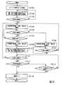
図6は、本発明の第1の実施形態に係る生体音収集装置1の押し当て状態提示処理の一例を示すフローチャートである。
ステップST101において、スイッチ部11は、使用者の操作により「オン」を表す操作信号を制御部13に出力する。
ステップST102において、制御部13は、接触状態検出部12および提示部141に生体面H31に対する接触面SMの押し当て状態の検出および当該押し当て状態の提示を開始させる。
ステップST103において、制御部13は、接触面SMが生体面H31に正常に接触しているか、すなわち、状態情報が接触状態を表す情報のみであるか否かを判定する。状態情報が接触状態を表す情報のみである場合、ステップST104に進む。一方、状態情報が接触状態を表す情報のみでない場合、ステップST102に戻る。FIG. 6 is a flowchart illustrating an example of the pressing state presentation process of the biological
In step ST <b> 101, the
In step ST102, the
In step ST103, the
ステップST104において、制御部13は、集音部15に生体音の取得・分析・再生を開始させる。
ステップST105において、制御部13は、接触面SMが生体面H31に正常に接触しているか、すなわち、状態情報が接触状態を表す情報のみであるか否かを判定する。状態情報が接触状態を表す情報のみである場合、ステップST108に進む。一方、状態情報が接触状態を表す情報のみでない場合、ステップST106に進む。
ステップST106において、制御部13は、集音部15に生体音の取得・分析・再生を一時停止させる。
ステップST107において、制御部13は、接触面SMが生体面H31に正常に接触しているか、すなわち、状態情報が接触状態を表す情報のみであるか否かを判定する。状態情報が接触状態を表す情報のみである場合、ステップST104に戻る。一方、状態情報が接触状態を表す情報のみでない場合、ステップST107を繰り返す。In step ST104, the
In step ST105, the
In step ST106, the
In step ST107, the
ステップST108において、制御部13は、生体音の取得・分析・再生に必要な所定の時間、例えば5秒間、接触面SMが生体面H31に正常に接触していたか否かを判定する。接触面SMが生体面H31に正常に接触していた場合、生体音の測定を終了し、ステップST109に進む。一方、接触面SMが生体面H31に正常に接触していない場合、ステップST105に戻る。
ステップST109において、制御部13は、集音部15に生体音の取得・分析・再生を停止させる。
ステップST110において、制御部13は、接触状態検出部12および提示部141に生体面H31に対する接触面SMの押し当て状態の検出および当該押し当て状態の提示を終了させる。
ステップST111において、制御部13は、再度、接触面SMが生体面H31に正常に接触している否か、すなわち、状態情報が接触状態を表す情報のみであるか否かを判定する。状態情報が接触状態を表す情報のみである場合、ステップST104に戻り、生体音の取得・分析・再生を開始する。一方、状態情報が接触状態を表す情報のみでない場合、ステップST112に進む。In step ST108, the
In step ST109, the
In step ST110, the
In step ST111, the
ステップST112において、上記測定が完了してから一定時間経過したか否かを判定する。一定時間経過した場合、ステップST114に進む。一方、一定時間経過していない場合、ステップST113に進む。
ステップST113において、制御部13は、スイッチ部11に使用者の操作により「オフ」を表す操作信号が入力されたか否かを判定する。入力された場合、ステップST114に進む。一方、入力されていない場合、ステップST111に戻る。
ステップST114において、制御部13は、電源をオフにし、押し当て状態提示処理を終了する。In step ST112, it is determined whether or not a predetermined time has elapsed since the completion of the measurement. If the predetermined time has elapsed, the process proceeds to step ST114. On the other hand, if the predetermined time has not elapsed, the process proceeds to step ST113.
In step ST <b> 113, the
In step ST114, the
このように、本実施形態によれば、生体音収集装置1は、被験者H3の生体音を収集する集音部15と、被験者H3の生体面H31への接触を検出する接触状態検出部12と、接触状態検出部12が検出した被験者H3の生体面H31への接触に基づいて、集音部15に生体音を収集させるか否かを判定する制御部13と、制御部13が集音部15に前記生体音を収集させないと判定した場合、接触状態検出部12が被験者H3の生体面H31に接触していないことを通知する情報通知部14と、を備える。 Thus, according to this embodiment, the biological
これにより、使用者は、生体面H31に対する生体音収集装置1における接触面SMの押し当て状態を、情報通知部14によりリアルタイムに確認することができ、接触面SMの押し当て方が適切でない場合、容易に押し当て方を修正することができるため、被験者H3の生体音を正確に聴診することができる。 Thereby, the user can confirm the pressing state of the contact surface SM in the biological
(第2の実施形態)
以下、図面を参照しながら本発明の第2の実施形態について詳しく説明する。
第1の実施形態では、生体音収集装置1の情報通知部14が生体面H31に対する接触面SMの押し当て状態を視覚に対して通知する場合について説明した。本実施形態では、生体音収集装置1Aの情報通知部14Aが生体面H31に対する接触面SMの押し当て状態を聴覚に対して通知する場合について説明する。(Second Embodiment)
Hereinafter, a second embodiment of the present invention will be described in detail with reference to the drawings.
In 1st Embodiment, the
図7は、本発明の第2の実施形態に係る生体音収集装置1Aの構成の一例を示す概略ブロック図である。
図3に示す第1の実施形態の生体音収集装置1の構成と、本実施形態の生体音収集装置1Aの構成とを比較すると、指示方向設定部17Aが追加されている。また、情報通知部14Aの構成が異なる。それ以外の構成は、生体音収集装置1と同様であるので、同一の符号を付して説明を省略する。FIG. 7 is a schematic block diagram showing an example of the configuration of the biological
When the configuration of the biological
指示方向設定部17Aは、例えば、リング状であり、生体音収集装置1Aの情報通知面OSと接触面SMとの中心が当該指示方向設定部17Aの中心と一致し、生体音収集装置1Aの筐体10Aの表面より内側に備えられる。指示方向設定部17Aは、リングの一部に指示方向の基準となる基準指示部を有する。指示方向設定部17Aは、使用者により回転させることが可能な構造で配置される。指示方向設定部17Aは、基準指示部の位置を表す情報を制御部13に出力する。 The indication
情報通知部14Aは、音声情報生成部142Aと、スピーカ143Aと、を含んで構成される。
音声情報生成部142Aは、制御部13から入力された基準指示部の位置を表す情報と状態情報とに基づいて、非接触状態であるセンサの位置(方向)を通知する音声信号を生成する。音声情報生成部142Aは、生成した音声信号を、スピーカ143Aを介して、使用者に生体面H31に対する接触面SMの押し当て状態を音で通知する。The
The sound
例えば、音声情報生成部142Aは、基準指示部が位置する方向を前方として、当該前方に対応する接触状態検出部12を構成するセンサが非接触状態である場合、「前方に傾けてください」との音声信号を生成する。また、音声情報生成部142Aは、基準指示部に対して右側の方向を生体音収集装置1Aの右として、当該右に対応する接触状態検出部12を構成するセンサが非接触状態である場合、「右に傾けてください」との音声信号を生成する。また、音声情報生成部142Aは、基準指示部の向きと反対の方向を手前として、当該手前に対応する接触状態検出部12を構成するセンサが非接触状態である場合、「手前に傾けてください」との音声信号を生成する。また、音声情報生成部142Aは、基準指示部に対して左の方向を生体音収集装置1Aの左として、当該左に対応する接触状態検出部12を構成するセンサが非接触状態である場合、「左に傾けてください」との音声信号を生成する。 For example, if the direction in which the reference instruction unit is located is the front and the sensor that configures the contact
なお、指示方向設定部17Aがリング状の一例を示し、指示方向の設定手段を説明したが、例えば、情報通知部14Aが第1の実施形態と同様に提示部141を備え、指示方向設定部17Aが、提示部141に指示方向の設定画面を表示させて、当該設定画面から指示方向の設定を受け付けてもよいし、指示方向設定部17Aが、提示部141のLEDと接触状態検出部12の各センサ121とを連動させて、接触状態検出部12の接触を検出したセンサ121のセンサ位置に応じて、指示方向の設定を受け付けてもよい。 The instruction
なお、第1の実施形態に係る情報通知部14の提示部141と、本実施形態に係る情報通知部14Aの音声情報生成部142Aおよびスピーカ143Aと、を組み合わせて、使用者の視覚と聴覚に対して、生体面H31に対する接触面SMの押し当て状態を通知してもよい。 Note that the
このように、本実施形態によれば、生体音収集装置1Aは、被験者H3の生体音を収集する集音部15と、被験者H3の生体面H31への接触を検出する接触状態検出部12と、接触状態検出部12が検出した被験者H3の生体面H31への接触に基づいて、集音部15に生体音を収集させるか否かを判定する制御部13と、制御部13が集音部15に生体音を収集させないと判定した場合、接触状態検出部12が被験者H3の生体面H31に接触していないことを通知する情報通知部14Aと、を備える。 Thus, according to the present embodiment, the biological
これにより、使用者は、生体面H31に対する生体音収集装置1Aにおける接触面SMの押し当て状態を、情報通知部14Aによりリアルタイムに確認することができ、接触面SMの押し当て方が適切でない場合、容易に押し当て方を修正することができるため、被験者H3の生体音を正確に聴診することができる。また、視覚による押し当て状態の確認が困難である場合であっても、押し当て状態を聴覚に通知することができる。 Thereby, the user can confirm the pressing state of the contact surface SM in the biological
(第3の実施形態)
以下、図面を参照しながら本発明の第3の実施形態について詳しく説明する。
第3の実施形態では、生体音収集装置1Bの情報通知部14Bが生体面H31に対する接触面SMの押し当て状態を触覚に対して通知する場合について説明する。
図8は、本発明の第3の実施形態に係る生体音収集装置1Bの構成の一例を示す概略ブロック図である。
第3の実施形態における生体音収集装置1Bの構成と、第1の実施形態における生体音収集装置1の構成とを比較すると、情報通知部14Bの構成が異なる。それ以外の構成は、第1の実施形態と同様の構成であるので、同一の符号を付して説明は省略する。(Third embodiment)
Hereinafter, the third embodiment of the present invention will be described in detail with reference to the drawings.
In the third embodiment, a case will be described in which the
FIG. 8 is a schematic block diagram showing an example of the configuration of the biological
When the configuration of the biological
情報通知部14Bは、アクチュエータ制御部144Bと、第1アクチュエータ145B−1と、第2アクチュエータ145B−2と、・・・、第Nアクチュエータ145B−Nと、を含んで構成される。
アクチュエータ制御部144Bは、第1アクチュエータ145B−1と、第2アクチュエータ145B−2と、・・・、第Nアクチュエータ145B−Nと、を制御する。具体的には、アクチュエータ制御部144Bは、制御部13から入力された状態情報に基づいて、非接触状態の接触状態検出部12のセンサに対応するアクチュエータを隆起させて、使用者に生体面H31に対する接触面SMの押し当て状態を触覚に通知する。The
The
図9(a)は、本発明の第3の実施形態に係る生体音収集装置1Bを情報通知面OSから見たときの上面図の一例であり、図9(b)は、生体音収集装置1Bの側面図の一例である。
図9(a)において、生体音収集装置1Bの筐体10Bの情報通知面OSの周囲には、複数のアクチュエータが円形に配置されている。例えば、情報通知面OSの周囲には、第1アクチュエータ145B−1、第2アクチュエータ145B−2、第3アクチュエータ145B−3、第4アクチュエータ145B−4、第5アクチュエータ145B−5、第6アクチュエータ145B−6、第7アクチュエータ145B−7、第8アクチュエータ
145B−8の八つのアクチュエータが配置される。
図9(a)の例では、接触状態検出部12の第3センサ121−3が非接触状態であり、当該第3センサ121−3に対応する第3アクチュエータ145B−3が隆起している一例である。FIG. 9A is an example of a top view when the biological
In FIG. 9A, a plurality of actuators are arranged in a circle around the information notification surface OS of the
In the example of FIG. 9A, the third sensor 121-3 of the contact
図9(b)において、生体音収集装置1Bの接触面SMと情報通知面OSとの間の筐体10Bには、スイッチ部11が配置され、当該スイッチ部11と情報通知面OSとの間に複数のアクチュエータが配置される。例えば、生体音収集装置1Bの筐体10Bの側面には、第2アクチュエータ145B−2と、第3アクチュエータ145B−3と、第4アクチュエータ145B−4と、第5アクチュエータ145B−5と、が配置されている。 In FIG. 9B, a
なお、当該アクチュエータは、接触状態検出部12を構成するセンサの数と同数であることが好ましいが、接触状態検出部12を構成するセンサの数とアクチュエータの数とが異なる場合であっても、図4(d)に示したように、測定値と推定値とから、使用者に生体面H31に対する接触面SMの押し当て状態を通知することが可能である。
また、第1の実施形態に係る情報通知部14の提示部141と、本実施形態に係る情報通知部14Bのアクチュエータ制御部144Bおよび複数のアクチュエータ145Bと、を組み合わせて、使用者の視覚および触覚に対して、生体面H31に対する接触面SMの押し当て状態を通知してもよい。The number of the actuators is preferably the same as the number of sensors constituting the contact
Further, the
なお、第2の実施形態に係る情報通知部14Aの音声情報生成部142Aおよびスピーカ143Aと、本実施形態に係る情報通知部14Bのアクチュエータ制御部144Bおよび複数のアクチュエータ145Bと、を組み合わせて、使用者の聴覚および触覚に対して、生体面H31に対する接触面SMの押し当て状態を通知してもよい。
また、第1の実施形態に係る情報通知部14の提示部141と、第2の実施形態に係る情報通知部14Aの音声情報生成部142Aおよびスピーカ143Aと、本実施形態に係る情報通知部14Bのアクチュエータ制御部144Bおよび複数のアクチュエータ145Bと、を組み合わせて、使用者の視覚、聴覚および触覚に対して、生体面H31に対する接触面SMの押し当て状態を通知してもよい。The voice
Also, the
このように、本実施形態によれば、生体音収集装置1Bは、被験者H3の生体音を収集する集音部15と、被験者H3の生体面H31への接触を検出する接触状態検出部12と、接触状態検出部12が検出した被験者H3の生体面H31への接触に基づいて、集音部15に生体音を収集させるか否かを判定する制御部13と、制御部13が集音部15に生体音を収集させないと判定した場合、接触状態検出部12が被験者H3の生体面H31に接触していないことを通知する情報通知部14Bと、を備える。 Thus, according to this embodiment, the biological
これにより、使用者は、生体面H31に生体音収集装置1Bにおける接触面SMの押し当て状態を、情報通知部14Bによりリアルタイムに確認することができ、接触面SMの押し当て方が適切でない場合、容易に押し当て方を修正することができるため、被験者H3の生体音を正確に聴診することができる。また、接触面SMの押し当て状態を視覚や聴覚により確認することが困難な場合であっても、当該押し当て状態を触覚で確認することができる。 Thereby, the user can confirm the pressing state of the contact surface SM in the biological
なお、上述した各実施形態において、接触面SMに集音部15と接触状態検出部12とが配置されると説明したが、接触状態検出部12が集音部15の生体面H31に対する押し当て状態を検出できれば、集音部15と接触状態検出部12とが同一の面に配置されなくてもよい。
なお、上述した各実施形態において、接触状態検出部12は、集音部15の周縁に配置されると説明したが、集音部15が備える振動板に影響を与えない位置、かつ、集音部15の生体面H31に対する押し当て状態を検出可能な位置であれば、集音部15の周縁に配置されなくてもよい。In each of the above-described embodiments, it has been described that the
In each of the above-described embodiments, it has been described that the contact
なお、上述した各実施形態において、生体音収集装置1、1A、1Bの筐体10、10A、10Bの外部に突起する基準指示部を備え、当該基準指示部に基づいて指示方向を通知してもよい。 In each of the above-described embodiments, the biological
なお、上述した各実施形態において、接触状態検出部12は、ピエゾ抵抗膜式のセンサであってもよいし、表面弾性波式のセンサであってもよいし、赤外線式のセンサであってもよいし、押し当てまたは接触を検出可能なセンサであればよい。また、制御部13が上述の判定に用いる閾値は、接触状態検出部12を構成する全てのセンサで同一であってもよいし、接触状態検出部12を構成するそれぞれのセンサで異なる閾値を用いてもよい。また、集音部15の周縁を八つの領域に分割してそれぞれの領域にセンサを配置したが、分割せずに周縁に一つのセンサを配置してもよいし、二つ以上の領域に分割してそれぞれの領域にセンサを配置してもよい。また、D/A部21は、イヤホン2の構成要素として説明したが、例えば、生体音収集装置1がD/A部21を含んでもよい。 In each of the embodiments described above, the contact
なお、上述した各実施形態において、生体音収集装置1、1A、1Bは、メモリを備え、集音部15が収集した生体音に対してデータ処理部16がデータ処理したデジタル信号を当該メモリに記憶させてもよい。 In each of the above-described embodiments, the biological
なお、上述した各実施形態における生体音収集装置1、1A、1Bの一部、または全部をコンピュータで実現するようにしても良い。その場合、この制御機能を実現するためのプログラムをコンピュータ読み取り可能な記録媒体に記録して、この記録媒体に記録されたプログラムをコンピュータシステムに読み込ませ、実行することによって実現しても良い。なお、ここでいう「コンピュータシステム」とは、生体音収集装置1、1A、1Bに内蔵されたコンピュータシステムであって、OSや周辺機器等のハードウェアを含むものとする。 In addition, you may make it implement | achieve a part or all of the biological
また、「コンピュータ読み取り可能な記録媒体」とは、フレキシブルディスク、光磁気ディスク、ROM、CD−ROM等の可搬媒体、コンピュータシステムに内蔵されるハードディスク等の記憶装置のことをいう。さらに「コンピュータ読み取り可能な記録媒体」とは、インターネット等のネットワークや電話回線等の通信回線を介してプログラムを送信する場合の通信線のように、短時間、動的にプログラムを保持するもの、その場合のサーバやクライアントとなるコンピュータシステム内部の揮発性メモリのように、一定時間プログラムを保持しているものも含んでも良い。
また上記プログラムは、前述した機能の一部を実現するためのものであっても良く、さらに前述した機能をコンピュータシステムにすでに記録されているプログラムとの組み合わせで実現できるものであっても良い。The “computer-readable recording medium” refers to a storage device such as a flexible medium, a magneto-optical disk, a portable medium such as a ROM and a CD-ROM, and a hard disk incorporated in a computer system. Furthermore, the “computer-readable recording medium” is a medium that dynamically holds a program for a short time, such as a communication line when transmitting a program via a network such as the Internet or a communication line such as a telephone line, In such a case, a volatile memory inside a computer system serving as a server or a client may be included and a program that holds a program for a certain period of time.
The program may be a program for realizing a part of the functions described above, and may be a program capable of realizing the functions described above in combination with a program already recorded in a computer system.
また、上述した各実施形態における生体音収集装置1、1A、1Bの一部、または全部を、LSI(Large Scale Integration)等の集積回路として実現しても良い。生体音収集装置1、1A、1Bの各機能ブロックは個別にプロセッサ化してもよいし、一部、または全部を集積してプロセッサ化しても良い。また、集積回路化の手法はLSIに限らず専用回路、または汎用プロセッサで実現しても良い。また、半導体技術の進歩によりLSIに代替する集積回路化の技術が出現した場合、当該技術による集積回路を用いても良い。 Moreover, you may implement | achieve part or all of the biological
以上、図面を参照してこの発明の各実施形態について詳しく説明してきたが、具体的な構成は上述のものに限られることはなく、この発明の要旨を逸脱しない範囲内において様々な設計変更等をすることが可能である。 As described above, the embodiments of the present invention have been described in detail with reference to the drawings. However, the specific configuration is not limited to that described above, and various design changes and the like can be made without departing from the scope of the present invention. It is possible to
(1)被験者の生体音を収集する集音部と、前記被験者の生体面への接触を検出する接触状態検出部と、前記接触状態検出部が検出した前記被験者の前記生体面への接触に基づいて、前記集音部に前記生体音を収集させるか否かを判定する制御部と、前記制御部が前記集音部に前記生体音を収集させないと判定した場合、前記接触状態検出部が前記被験者の前記生体面に接触していないことを通知する情報通知部と、を備えることを特徴とする生体音収集装置。 (1) A sound collection unit that collects a subject's biological sound, a contact state detection unit that detects contact of the subject with the biological surface, and contact of the subject with the biological surface detected by the contact state detection unit Based on the control unit that determines whether or not the sound collection unit collects the body sound, and the control unit determines that the sound collection unit does not collect the body sound, the contact state detection unit A biological sound collection device comprising: an information notification unit that notifies that the subject is not in contact with the biological surface.
(2)前記接触状態検出部は、複数のセンサを含み、当該複数のセンサは、前記集音部の周縁のそれぞれ異なる箇所に配置され、前記情報通知部は、前記複数のセンサのうち、前記被験者の前記生体面への接触を検出しないセンサの箇所を通知することを特徴とする(1)に記載の生体音収集装置。 (2) The contact state detection unit includes a plurality of sensors, and the plurality of sensors are arranged at different locations on the periphery of the sound collection unit, and the information notification unit includes the sensor among the plurality of sensors. The biological sound collecting apparatus according to (1), wherein a location of a sensor that does not detect contact of the subject with the biological surface is notified.
(3)前記情報通知部は、発光素子または表示部を備え、前記複数のセンサのうち、前記被験者の前記生体面への接触を検出しないセンサの箇所に対応する前記発光素子を発光、または前記被験者の前記生体面への接触を検出しない前記センサの箇所を前記表示部に表示させることを特徴とする(1)または(2)に記載の生体音収集装置。 (3) The information notification unit includes a light-emitting element or a display unit, and emits the light-emitting element corresponding to the position of the sensor that does not detect contact of the subject with the biological surface among the plurality of sensors, or the The biological sound collection apparatus according to (1) or (2), wherein a location of the sensor that does not detect contact of the subject with the biological surface is displayed on the display unit.
(4)前記情報通知部が前記被験者の前記生体面への接触を検出しないセンサの箇所を通知するときの基準指示方向を決定する指示方向設定部をさらに備え、前記情報通知部は、前記指示方向設定部により決定された基準指示方向に応じて、前記複数のセンサのうち、前記被験者の前記生体面への接触を検出しないセンサの箇所を音で通知することを特徴とする(1)から(3)のいずれか一項に記載の生体音収集装置。 (4) The information notification unit further includes an instruction direction setting unit that determines a reference instruction direction when notifying the location of the sensor that does not detect contact of the subject with the biological surface, and the information notification unit includes the instruction According to the reference indicating direction determined by the direction setting unit, the position of the sensor that does not detect contact of the subject with the biological surface among the plurality of sensors is notified by sound (1) The biological sound collection device according to any one of (3).
(5)前記情報通知部は、前記生体音収集装置の筐体に設けられたアクチュエータを含んで構成され、前記複数のセンサのうち、前記被験者の前記生体面への接触を検出しないセンサの箇所に対応するアクチュエータを隆起させて通知することを特徴とする(2)から(4)のいずれか一項に記載の生体音収集装置。 (5) The information notification unit is configured to include an actuator provided in a housing of the biological sound collection device, and among the plurality of sensors, a location of a sensor that does not detect contact of the subject with the biological surface The living body sound collecting device according to any one of (2) to (4), wherein the actuator corresponding to is raised and notified.
1、1A、1B・・・生体音収集装置、10、10A、10B・・・筐体、11・・・スイッチ部、12・・・接触状態検出部、121−1・・・第1センサ、121−2・・・第2センサ、121−3・・・第3センサ、121−4・・・第4センサ、121−5・・・第5センサ、121−6・・・第6センサ、121−7・・・第7センサ、121−8・・・第8センサ、121−N・・・第Nセンサ、13・・・制御部、14、14A、14B・・・情報通知部、141・・・提示部、142A・・・音声情報生成部、143A・・・スピーカ、144B・・・アクチュエータ制御部、145B−1・・・第1アクチュエータ、145B−2・・・第2アクチュエータ、145B−3・・・第3アクチュエータ、145B−4・・・第4アクチュエータ、145B−5・・・第5アクチュエータ、145B−N・・・第Nアクチュエータ、15・・・集音部、151・・・マイク、152・・・A/D部、16・・・データ処理部、17A・・・指示方向設定部、2・・・イヤホン、21・・・D/A部、22・・・スピーカDESCRIPTION OF
Claims (5)
Translated fromJapanese前記被験者の生体面への接触を検出する接触状態検出部と、
前記接触状態検出部が検出した前記被験者の前記生体面への接触に基づいて、前記集音部に前記生体音を収集させるか否かを判定する制御部と、
前記制御部が前記集音部に前記生体音を収集させないと判定した場合、前記接触状態検出部が前記被験者の前記生体面に接触していないことを通知する情報通知部と、
を備えることを特徴とする生体音収集装置。A sound collection unit for collecting the body sound of the subject;
A contact state detection unit for detecting contact of the subject with the biological surface;
A control unit that determines whether or not the sound collection unit collects the biological sound based on the contact of the subject with the biological surface detected by the contact state detection unit;
An information notification unit for notifying that the contact state detection unit is not in contact with the biological surface of the subject, when the control unit determines that the sound collection unit does not collect the biological sound;
A biological sound collecting apparatus comprising:
当該複数のセンサは、前記集音部の周縁のそれぞれ異なる箇所に配置され、
前記情報通知部は、
前記複数のセンサのうち、前記被験者の前記生体面への接触を検出しないセンサの箇所を通知すること
を特徴とする請求項1に記載の生体音収集装置。The contact state detection unit includes a plurality of sensors,
The plurality of sensors are arranged at different locations on the periphery of the sound collection unit,
The information notification unit
The biological sound collection device according to claim 1, wherein, among the plurality of sensors, a location of a sensor that does not detect contact of the subject with the biological surface is notified.
前記複数のセンサのうち、前記被験者の前記生体面への接触を検出しないセンサの箇所に対応する前記発光素子を発光、または前記被験者の前記生体面への接触を検出しない前記センサの箇所を前記表示部に表示させること
を特徴とする請求項2に記載の生体音収集装置。The information notification unit includes a light emitting element or a display unit,
Among the plurality of sensors, the light emitting element corresponding to the location of the sensor that does not detect contact of the subject with the biological surface is emitted, or the location of the sensor that does not detect contact of the subject with the biological surface is The biological sound collecting apparatus according to claim 2, wherein the biological sound collecting apparatus is displayed on a display unit.
をさらに備え、
前記情報通知部は、前記指示方向設定部により決定された基準指示方向に応じて、前記複数のセンサのうち、前記被験者の前記生体面への接触を検出しないセンサの箇所を音で通知すること
を特徴とする請求項2または請求項3に記載の生体音収集装置。An instruction direction setting unit for determining a reference instruction direction when the information notification unit notifies the location of the sensor that does not detect contact of the subject with the biological surface;
The information notification unit notifies, by sound, of the plurality of sensors that do not detect contact of the subject with the biological surface according to the reference instruction direction determined by the instruction direction setting unit. The biological sound collection device according to claim 2 or claim 3, wherein
を特徴とする請求項2から請求項4のいずれか一項に記載の生体音収集装置。The information notification unit includes an actuator provided in a housing of the biological sound collection device, and corresponds to a sensor location that does not detect contact of the subject with the biological surface among the plurality of sensors. The biological sound collection device according to any one of claims 2 to 4, wherein the actuator is raised and notified.
Priority Applications (3)
| Application Number | Priority Date | Filing Date | Title |
|---|---|---|---|
| JP2013153005AJP2015020030A (en) | 2013-07-23 | 2013-07-23 | Body sound collection device |
| PCT/JP2014/069324WO2015012265A1 (en) | 2013-07-23 | 2014-07-22 | Biological-sound collection device and biological-sound collection method |
| US14/770,858US20160007923A1 (en) | 2013-07-23 | 2014-07-22 | Biological sound collecting device and biological sound collecting method |
Applications Claiming Priority (1)
| Application Number | Priority Date | Filing Date | Title |
|---|---|---|---|
| JP2013153005AJP2015020030A (en) | 2013-07-23 | 2013-07-23 | Body sound collection device |
Publications (1)
| Publication Number | Publication Date |
|---|---|
| JP2015020030Atrue JP2015020030A (en) | 2015-02-02 |
Family
ID=52393300
Family Applications (1)
| Application Number | Title | Priority Date | Filing Date |
|---|---|---|---|
| JP2013153005APendingJP2015020030A (en) | 2013-07-23 | 2013-07-23 | Body sound collection device |
Country Status (3)
| Country | Link |
|---|---|
| US (1) | US20160007923A1 (en) |
| JP (1) | JP2015020030A (en) |
| WO (1) | WO2015012265A1 (en) |
Cited By (8)
| Publication number | Priority date | Publication date | Assignee | Title |
|---|---|---|---|---|
| WO2016143116A1 (en)* | 2015-03-12 | 2016-09-15 | パイオニア株式会社 | Stethoscope |
| JP2017000198A (en)* | 2015-06-04 | 2017-01-05 | 日本光電工業株式会社 | Electronic auscultation system |
| WO2017159752A1 (en)* | 2016-03-18 | 2017-09-21 | Ami株式会社 | Stethoscope |
| JP2017170112A (en)* | 2016-03-18 | 2017-09-28 | Ami株式会社 | Stethoscope |
| WO2019198770A1 (en)* | 2018-04-13 | 2019-10-17 | オムロンヘルスケア株式会社 | Bioacoustic measurement apparatus, bioacoustic measurement assistance method, bioacoustic measurement assistance program |
| WO2019203097A1 (en)* | 2018-04-18 | 2019-10-24 | オムロンヘルスケア株式会社 | Biological sound measurement device, biological sound measurement assistance method, and biological sound measurement assistance program |
| DE112020000205T5 (en) | 2019-02-06 | 2021-08-19 | Omron Healthcare Co., Ltd. | Biological sound measuring device, control method for biological sound measuring device and control program for biological sound measuring device |
| JP2022088956A (en)* | 2020-12-03 | 2022-06-15 | 株式会社oneA | Respiratory sound measuring device |
Families Citing this family (6)
| Publication number | Priority date | Publication date | Assignee | Title |
|---|---|---|---|---|
| US9818854B2 (en)* | 2015-04-30 | 2017-11-14 | Semiconductor Components Industries, Llc | Electronic device including a bidirectional HEMT |
| CN108292659B (en)* | 2016-09-30 | 2021-12-17 | 新电元工业株式会社 | Semiconductor device with a plurality of semiconductor chips |
| US12029606B2 (en)* | 2017-09-05 | 2024-07-09 | Sanolla Ltd. | Electronic stethoscope with enhanced features |
| EP3684261A1 (en)* | 2017-09-19 | 2020-07-29 | Ausculsciences, Inc. | System and method for detecting decoupling of an auscultatory sound sensor from a test-subject |
| US11045163B2 (en) | 2017-09-19 | 2021-06-29 | Ausculsciences, Inc. | Method of detecting noise in auscultatory sound signals of a coronary-artery-disease detection system |
| USD1042851S1 (en) | 2021-06-16 | 2024-09-17 | Sanolla Ltd. | Medical diagnostic device |
Citations (2)
| Publication number | Priority date | Publication date | Assignee | Title |
|---|---|---|---|---|
| JP2012200383A (en)* | 2011-03-25 | 2012-10-22 | Panasonic Corp | Bioacoustic processing apparatus and bioacoustic processing method |
| JP2013123493A (en)* | 2011-12-13 | 2013-06-24 | Sharp Corp | Information processing apparatus, stethoscope, control method for information processing apparatus, control program, and recording medium |
Family Cites Families (7)
| Publication number | Priority date | Publication date | Assignee | Title |
|---|---|---|---|---|
| IL116699A (en)* | 1996-01-08 | 2001-09-13 | Biosense Ltd | Method of constructing cardiac map |
| US20030229267A1 (en)* | 2000-12-15 | 2003-12-11 | Amir Belson | Obstetrical imaging system and integrated fetal vacuum extraction system |
| US20040096069A1 (en)* | 2002-11-14 | 2004-05-20 | Jen-Chien Chien | Electronic stethoscope |
| US20090028003A1 (en)* | 2007-07-24 | 2009-01-29 | International Business Machines Corporation | Apparatus and method for sensing of three-dimensional environmental information |
| US9125678B2 (en)* | 2008-09-17 | 2015-09-08 | Inertial Orthopaedic Navigation Solutions Pty Ltd | Surgical orientation system and associated method |
| US20100137845A1 (en)* | 2008-12-03 | 2010-06-03 | Immersion Corporation | Tool Having Multiple Feedback Devices |
| JP5819183B2 (en)* | 2011-02-03 | 2015-11-18 | アークレイ株式会社 | Analysis device, sensor inspection device, inspection method, and inspection program |
- 2013
- 2013-07-23JPJP2013153005Apatent/JP2015020030A/enactivePending
- 2014
- 2014-07-22WOPCT/JP2014/069324patent/WO2015012265A1/enactiveApplication Filing
- 2014-07-22USUS14/770,858patent/US20160007923A1/ennot_activeAbandoned
Patent Citations (2)
| Publication number | Priority date | Publication date | Assignee | Title |
|---|---|---|---|---|
| JP2012200383A (en)* | 2011-03-25 | 2012-10-22 | Panasonic Corp | Bioacoustic processing apparatus and bioacoustic processing method |
| JP2013123493A (en)* | 2011-12-13 | 2013-06-24 | Sharp Corp | Information processing apparatus, stethoscope, control method for information processing apparatus, control program, and recording medium |
Cited By (16)
| Publication number | Priority date | Publication date | Assignee | Title |
|---|---|---|---|---|
| JPWO2016143116A1 (en)* | 2015-03-12 | 2017-11-02 | パイオニア株式会社 | Stethoscope |
| WO2016143116A1 (en)* | 2015-03-12 | 2016-09-15 | パイオニア株式会社 | Stethoscope |
| JP2017000198A (en)* | 2015-06-04 | 2017-01-05 | 日本光電工業株式会社 | Electronic auscultation system |
| US11116473B2 (en) | 2016-03-18 | 2021-09-14 | Ami Inc. | Stethoscope |
| WO2017159752A1 (en)* | 2016-03-18 | 2017-09-21 | Ami株式会社 | Stethoscope |
| JP2017170112A (en)* | 2016-03-18 | 2017-09-28 | Ami株式会社 | Stethoscope |
| WO2019198770A1 (en)* | 2018-04-13 | 2019-10-17 | オムロンヘルスケア株式会社 | Bioacoustic measurement apparatus, bioacoustic measurement assistance method, bioacoustic measurement assistance program |
| JP2019180988A (en)* | 2018-04-13 | 2019-10-24 | オムロンヘルスケア株式会社 | Biological sound measuring apparatus, biological sound measurement support method, and biological sound measurement support program |
| US11278258B2 (en) | 2018-04-13 | 2022-03-22 | Omron Healthcare Co., Ltd. | Biological sound measuring device, biological sound measurement support method, and biological sound measurement support program |
| JP2019187528A (en)* | 2018-04-18 | 2019-10-31 | オムロンヘルスケア株式会社 | Biological sound measuring device, biological sound measurement support method, and biological sound measurement support program |
| WO2019203097A1 (en)* | 2018-04-18 | 2019-10-24 | オムロンヘルスケア株式会社 | Biological sound measurement device, biological sound measurement assistance method, and biological sound measurement assistance program |
| US12383221B2 (en) | 2018-04-18 | 2025-08-12 | Omron Healthcare Co., Ltd. | Biological sound measuring device, biological sound measurement support method, and biological sound measurement support program |
| DE112020000205T5 (en) | 2019-02-06 | 2021-08-19 | Omron Healthcare Co., Ltd. | Biological sound measuring device, control method for biological sound measuring device and control program for biological sound measuring device |
| US12138105B2 (en) | 2019-02-06 | 2024-11-12 | Omron Healthcare Co., Ltd. | Biological sound measurement device, control method for biological sound measurement device, and non-transitory recording medium storing control program for biological sound measurement device |
| JP2022088956A (en)* | 2020-12-03 | 2022-06-15 | 株式会社oneA | Respiratory sound measuring device |
| JP7607902B2 (en) | 2020-12-03 | 2025-01-06 | 株式会社oneA | Respiratory sound measuring device |
Also Published As
| Publication number | Publication date |
|---|---|
| US20160007923A1 (en) | 2016-01-14 |
| WO2015012265A1 (en) | 2015-01-29 |
Similar Documents
| Publication | Publication Date | Title |
|---|---|---|
| JP2015020030A (en) | Body sound collection device | |
| JP6637475B2 (en) | Electronics | |
| KR102535726B1 (en) | Method for detecting earphone position, storage medium and electronic device therefor | |
| US10229754B2 (en) | Wearable device obtaining audio data for diagnosis | |
| US10130287B2 (en) | Hearing test system | |
| CN107405129A (en) | Systems, devices and methods for capturing and outputting data about physical characteristics | |
| JP6263613B2 (en) | Wearable device assembly with a function to reduce data loss due to component failure | |
| JP2009160373A (en) | Physiological condition measuring device | |
| US9947187B2 (en) | Haptic notification system with rules for notification that can be altered to increase effectiveness | |
| US20180120930A1 (en) | Use of Body-Area Network (BAN) as a Kinetic User Interface (KUI) | |
| WO2013191278A1 (en) | Electronic apparatus and control program as well as information notification method | |
| CN112956220A (en) | Fall detection-Audio cycling | |
| WO2023084304A2 (en) | Electronic stethoscope | |
| KR20070014809A (en) | Method, device, and mobile device for providing information during a call | |
| CN107111790A (en) | Use computing devices to control the output of contextual information | |
| JP2014175776A (en) | Portable terminal device, method for controlling portable terminal device, and program for controlling portable terminal device | |
| JP2018042137A (en) | Electronic device, control device, control program, and sensitivity inspection method | |
| JP6719373B2 (en) | Judgment system, judgment method, and judgment program | |
| US12089931B1 (en) | Optical sensor for skin-contact detection and physiological parameter measurement at wearable electronic device | |
| US11792575B1 (en) | Electronic device with flexible housings | |
| KR20150041458A (en) | Apparatus for auscultation training | |
| CN110972461B (en) | Middle ear sound transmission characteristic evaluation system and measurement probe | |
| JP6303825B2 (en) | Input device | |
| EP3162286A1 (en) | Measurement device and measurement method | |
| JP2024062262A (en) | Auscultation device and auscultation method |
Legal Events
| Date | Code | Title | Description |
|---|---|---|---|
| RD04 | Notification of resignation of power of attorney | Free format text:JAPANESE INTERMEDIATE CODE: A7424 Effective date:20150518 | |
| A621 | Written request for application examination | Free format text:JAPANESE INTERMEDIATE CODE: A621 Effective date:20160331 | |
| A131 | Notification of reasons for refusal | Free format text:JAPANESE INTERMEDIATE CODE: A131 Effective date:20161108 | |
| A02 | Decision of refusal | Free format text:JAPANESE INTERMEDIATE CODE: A02 Effective date:20170509 |