JP2015016545A - Pilot hole drilling jig and rehabilitation pipe connection hole drilling method - Google Patents
Pilot hole drilling jig and rehabilitation pipe connection hole drilling methodDownload PDFInfo
- Publication number
- JP2015016545A JP2015016545AJP2014122162AJP2014122162AJP2015016545AJP 2015016545 AJP2015016545 AJP 2015016545AJP 2014122162 AJP2014122162 AJP 2014122162AJP 2014122162 AJP2014122162 AJP 2014122162AJP 2015016545 AJP2015016545 AJP 2015016545A
- Authority
- JP
- Japan
- Prior art keywords
- pipe
- pilot hole
- drilling jig
- hole
- mounting
- Prior art date
- Legal status (The legal status is an assumption and is not a legal conclusion. Google has not performed a legal analysis and makes no representation as to the accuracy of the status listed.)
- Granted
Links
- 238000005553drillingMethods0.000titleclaimsabstractdescription113
- 238000000034methodMethods0.000titleclaimsdescription19
- 230000002093peripheral effectEffects0.000claimsabstractdescription35
- 238000005520cutting processMethods0.000claimsabstractdescription6
- 238000003860storageMethods0.000claimsdescription14
- 239000004570mortar (masonry)Substances0.000description8
- 239000012779reinforcing materialSubstances0.000description6
- 239000002184metalSubstances0.000description5
- 239000000463materialSubstances0.000description4
- 229910000831SteelInorganic materials0.000description3
- 239000002131composite materialSubstances0.000description3
- 229910003460diamondInorganic materials0.000description3
- 239000010432diamondSubstances0.000description3
- 230000002787reinforcementEffects0.000description3
- 239000010959steelSubstances0.000description3
- 238000003780insertionMethods0.000description2
- 230000037431insertionEffects0.000description2
- 230000004048modificationEffects0.000description2
- 238000012986modificationMethods0.000description2
- 239000002245particleSubstances0.000description2
- 238000004804windingMethods0.000description2
- 238000001816coolingMethods0.000description1
- 238000010438heat treatmentMethods0.000description1
- 238000009434installationMethods0.000description1
- 238000005304joiningMethods0.000description1
- 230000009191jumpingEffects0.000description1
- 238000004519manufacturing processMethods0.000description1
- 229920000915polyvinyl chloridePolymers0.000description1
- 239000004800polyvinyl chlorideSubstances0.000description1
- 230000000630rising effectEffects0.000description1
- 239000000057synthetic resinSubstances0.000description1
- 229920003002synthetic resinPolymers0.000description1
- 238000007740vapor depositionMethods0.000description1
Images


Landscapes
- Drilling And Boring (AREA)
Abstract
Translated fromJapaneseDescription
Translated fromJapaneseこの発明は、既設管を更生する更生管に既設管と取付管との取付管口に対応してパイロット孔を形成するパイロット孔削孔治具、及び更生管に形成されたパイロット孔に基づいて更生管に接続口を形成する更生管の接続口削孔方法に関するものである。 The present invention is based on a pilot hole drilling jig for forming a pilot hole in a rehabilitation pipe for rehabilitating an existing pipe corresponding to a mounting pipe port between the existing pipe and a mounting pipe, and a pilot hole formed in the rehabilitation pipe. The present invention relates to a connection hole drilling method for a rehabilitation pipe that forms a connection opening in the rehabilitation pipe.
従来より、老朽化した既設管、例えば、下水道管等を更生するため、両側縁部に接合部が形成された帯状部材を既設管内に引込み、螺旋状に巻き回して隣接する帯状部材の接合部同士を互いに接合して更生管を製管するとともに、製管された更生管に新たに帯状部材を供給して更生管を既設管の軸心方向に付加形成することが実施されている。 Conventionally, in order to rehabilitate an aged existing pipe, for example, a sewer pipe, a band-shaped member with joints formed on both side edges is drawn into the existing pipe and spirally wound to join adjacent band-shaped members. The rehabilitating pipe is manufactured by joining them together, and a new strip member is supplied to the manufactured rehabilitating pipe so that the rehabilitating pipe is additionally formed in the axial direction of the existing pipe.
一方、既設管に地上側のマス等から取付管が接続されている場合には、既設管を更生する更生管に取付管を接続する必要がある。この場合、マス等からホールソーを取付管内に挿入し、ホールソーを回転させて更生管に目印となる仮孔であるパイロット孔を削孔した後、更生管内に削孔刃を搭載した削孔装置を搬入し、パイロット孔の周囲を削孔して既設管と取付管との取付管口に連通する接続口を形成するようにしている(例えば、特許文献1参照)。 On the other hand, when an attachment pipe is connected to an existing pipe from a ground mass or the like, it is necessary to connect the attachment pipe to a rehabilitation pipe that rehabilitates the existing pipe. In this case, a hole saw is inserted into the mounting pipe from a mass, etc., and the hole saw is rotated to drill a pilot hole, which is a temporary hole as a mark on the rehabilitation pipe. It carries in, and the periphery of a pilot hole is drilled and the connection port connected to the attachment pipe port of an existing pipe and an attachment pipe is formed (for example, refer patent document 1).
ところで、取付管は、マス等から屈曲して既設管に接続されていることが多く、取付管の屈曲部を通過させるためには、ホールソーの外径は取付管の内径の約1/2程度に制約される。また、取付管は、既設管に対して管軸方向および周方向に設定角度傾斜して接続されている場合には、既設管と取付管との取付管口は楕円形状となっている。したがって、取付管よりも小径のホールソーをフレキシブルシャフトを利用して回転させ、楕円形状の取付管口の中心に位置して更生管にパイロット孔を削孔することは容易でない。 By the way, the mounting pipe is often bent from a mass or the like and connected to the existing pipe. In order to pass the bent portion of the mounting pipe, the outer diameter of the hole saw is about 1/2 of the inner diameter of the mounting pipe. Constrained by In addition, when the attachment pipe is connected to the existing pipe at a set angle in the tube axis direction and the circumferential direction, the attachment pipe port between the existing pipe and the attachment pipe has an elliptical shape. Therefore, it is not easy to rotate a hole saw having a diameter smaller than that of the attachment pipe by using a flexible shaft and drill a pilot hole in the rehabilitation pipe at the center of the elliptical attachment pipe opening.
一方、既設管と更生管との隙間にモルタルを充填して更生管とともに形成される複合管の強度を向上させるため、鋼板等の金属製補強材を装着した補強材付き帯状部材を螺旋状に巻き回して更生管を製管した場合には、更生管の周囲に金属製補強材が螺旋状に装着される。このような更生管にパイロット孔を形成する場合、回転するホールソーが更生管の金属製補強材に接触すると、衝撃により取付管とホールソーとの内外径差分飛び跳ねてテレビカメラ等によって設定した中心位置から逸脱することが多く、中心位置に確実にパイロット孔を削孔することは極めて困難である。仮に、楕円形状の取付管口の中心を外れて更生管にパイロット孔が削孔されると、更生管に搬入された削孔装置がパイロット孔を目印として更生管に接続口を形成するため、更生管とともに既設管と取付管との接続部分を切削することになり、更生管と取付管との接続に支障を来すことになる。この結果、熟練した作業者によっても試行錯誤しつつパイロット孔を削孔せざるを得ないことから、多くの時間を必要とし、作業効率が低いという問題があった。 On the other hand, in order to improve the strength of the composite pipe formed with the rehabilitation pipe by filling the gap between the existing pipe and the rehabilitation pipe, the belt-like member with the reinforcement attached with the metal reinforcement such as a steel plate is spiraled. When the rehabilitation pipe is formed by winding, a metal reinforcing material is helically attached around the rehabilitation pipe. When a pilot hole is formed in such a rehabilitation pipe, when the rotating hole saw comes into contact with the metal reinforcement of the rehabilitation pipe, the difference between the inner and outer diameters of the mounting pipe and the hole saw jumps from the center position set by the TV camera etc. It often deviates and it is extremely difficult to drill the pilot hole reliably at the center position. Temporarily, when the pilot hole is drilled in the rehabilitation pipe off the center of the elliptical mounting pipe port, the drilling device carried into the rehabilitation pipe forms a connection port in the rehabilitation pipe with the pilot hole as a mark. The connection part of an existing pipe and an attachment pipe will be cut with a rehabilitation pipe, and it will interfere with the connection of a rehabilitation pipe and an attachment pipe. As a result, even a skilled worker has to drill the pilot hole through trial and error, so that a lot of time is required and the working efficiency is low.
本発明は、このような問題点に鑑みてなされたものであり、補強材付き帯状部材によって製管された更生管であっても、既設管と取付管との取付管口の略中心に位置してパイロット孔を確実に形成することのできるパイロット孔削孔治具を提供するとともに、パイロット孔削孔治具によって形成されたパイロット孔に基づいて更生管に取付管口に連通する接続口を効率よく形成することのできる更生管の接続口削孔方法を提供することを目的としている。 The present invention has been made in view of such a problem, and even a rehabilitated pipe manufactured by a belt-like member with a reinforcing material is positioned at substantially the center of the mounting pipe port between the existing pipe and the mounting pipe. In addition to providing a pilot hole drilling jig that can reliably form the pilot hole, a connection port that communicates with the attachment pipe port on the rehabilitation pipe based on the pilot hole formed by the pilot hole drilling jig is provided. It aims at providing the connection hole drilling method of the rehabilitation pipe which can be formed efficiently.
前記の目的を達成するための本発明の解決手段は、取付管が接続された既設管を更生した更生管に、既設管と取付管との取付管口に対応してパイロット孔を形成するパイロット孔削孔治具であって、外周面にパッカーを設けるとともに、内周面に回転機能および摺動機能を備えるベアリングを設けた支持筒部材と、切削刃を設けた筒状本体および筒状本体に連結されたシャフトを有するホールソーとを備えて構成される。前記ホールソーは、前記シャフトが、前記支持筒部材にベアリングを介して回転自在に、かつ軸心方向に移動自在に支持されるとともに、このシャフトにフレキシブルシャフトが連結可能となるように形成される。そして、前記パッカーは圧力空気が供給されて膨張し、このパッカーを介して取付管に対して取付管の軸心とホールソーの軸心を一致させるようにホールソーを支持し、前記ホールソーを回転させながら軸心方向に押し込み、ホールソーを取付管口の略中心に位置させて、更生管にパイロット孔を形成するように構成されている。 In order to achieve the above-mentioned object, the solution means of the present invention is a pilot that forms a pilot hole in a rehabilitation pipe obtained by rehabilitating an existing pipe to which a mounting pipe is connected, corresponding to a mounting pipe port between the existing pipe and the mounting pipe. A drilling hole jig having a support cylinder member provided with a bearing having a rotation function and a sliding function on an inner peripheral surface, and a cylindrical main body and a cylindrical main body provided with a cutting blade. And a hole saw having a shaft coupled thereto. The hole saw is formed such that the shaft is rotatably supported by the support cylinder member via a bearing and movable in the axial direction, and a flexible shaft can be connected to the shaft. The packer expands when pressurized air is supplied, and supports the hole saw through the packer so that the axis of the mounting pipe and the axis of the hole saw are aligned with the mounting pipe, while rotating the hole saw. A pilot hole is formed in the rehabilitation pipe by pushing in the axial direction and positioning the hole saw at the approximate center of the attachment pipe port.
本発明によれば、圧力空気を供給することによりパッカーが膨張して、取付管に対して取付管の軸心とホールソーの軸心とを一致させてホールソーを支持することができる。また、ホールソーは、支持筒部材に設けられた回転機能および摺動機能を備えるベアリングによって回転自在に、かつ、軸心方向に移動自在に支持されている。これにより、既設管を更生管によって更生した後、取付管内にパイロット孔削孔治具を挿入し、既設管と取付管との取付管口の近傍に位置してパイロット孔削孔治具を支持するとともに、フレキシブルシャフトを介してホールソーを回転させて押し込むことにより、取付管口の略中心に位置して更生管にパイロット孔を確実に形成することができる。 According to the present invention, the packer is expanded by supplying pressurized air, and the hole saw can be supported by aligning the axis of the attachment tube and the axis of the hole saw with respect to the attachment tube. Further, the hole saw is supported by a bearing having a rotating function and a sliding function provided on the support cylinder member so as to be rotatable and movable in the axial direction. As a result, after the existing pipe is rehabilitated with the rehabilitation pipe, the pilot hole drilling jig is inserted into the mounting pipe, and the pilot hole drilling jig is supported in the vicinity of the mounting pipe port between the existing pipe and the mounting pipe. In addition, by rotating and pushing the hole saw through the flexible shaft, it is possible to reliably form the pilot hole in the rehabilitation pipe at the approximate center of the attachment pipe port.
また、前記構成のパイロット孔削孔治具において、支持筒部材は、前記筒状本体を内側に収納しうる収納部を備えて、前記シャフトが軸心方向に移動することにより、該筒状本体が前記支持筒部材の収納部から出没自在とされてもよい。 Further, in the pilot hole drilling jig having the above-described configuration, the support cylinder member includes a storage portion that can store the cylindrical body inside, and the cylindrical body moves when the shaft moves in the axial direction. May be allowed to appear and retract from the storage portion of the support cylinder member.
このように構成されることによって、支持筒部材の内側にホールソーの筒状本体が収納されたときには、パイロット孔削孔治具をコンパクトな状態に形成することができ、パイロット孔を設ける取付管口までの管路に、パイロット孔削孔治具を挿入しやすくすることができる。また、ホールソーの筒状本体は支持筒部材の収納部から出没自在であるので、取付管口の削孔時には支持筒部材から押し出されて回転し、取付管口にパイロット孔を形成することができる。 With this configuration, when the cylindrical main body of the hole saw is housed inside the support cylinder member, the pilot hole drilling jig can be formed in a compact state, and the mounting pipe port in which the pilot hole is provided It is possible to easily insert the pilot hole drilling jig into the pipe line. Further, since the cylindrical main body of the hole saw can be freely protruded and retracted from the storage portion of the support tube member, when the mounting tube port is drilled, it can be pushed out of the support tube member and rotated to form a pilot hole in the mounting tube port. .
さらに、前記支持筒部材は、パッカーの内側に連通する流路を備え、この流路には、パッカーを膨張させる圧力空気の供給配管が、耐衝撃性を有する硬質管状体を介して接続されることが好ましい。 Further, the support cylinder member includes a flow path communicating with the inside of the packer, and a supply pipe for pressurized air for expanding the packer is connected to the flow path via a hard tubular body having impact resistance. It is preferable.
このように構成されることによって、パイロット孔削孔治具を取付管口までの管路に挿入する際に、圧力空気の供給配管と硬質管状体とを介して支持筒部材を押し込むことができ、多様な配管経路に対応させて挿入することが可能となり、作業性が高められる。 With this configuration, when inserting the pilot hole drilling jig into the pipe line up to the attachment pipe port, the support cylinder member can be pushed in via the pressurized air supply pipe and the rigid tubular body. Therefore, it is possible to insert it corresponding to various piping routes, and workability is improved.
また、前記パイロット孔削孔治具を用いた更生管の接続口削孔方法も本発明の技術的思想の範疇である。すなわち、本発明の更生管の接続口削孔方法は、取付管が接続された既設管を更生した更生管に、既設管と取付管との取付管口に連通する接続口を形成する接続口削孔方法であって、前記構成に係るパイロット孔削孔治具を地上側から取付管内に挿入し、支持した後、ホールソーを回転させながら押し込んで更生管にパイロット孔を形成し、次いで、中心部に識別マークを有する削孔刃を搭載した削孔装置を更生管からパイロット孔を臨む位置まで搬送し、パイロット孔を通して削孔刃の識別マークを視認した状態で削孔刃を介してパイロット孔の周縁部を複数回削孔し、更生管に取付管口に連通する接続口を形成することを特徴としている。 Further, a method for drilling a rehabilitating pipe using the pilot hole drilling jig is also within the scope of the technical idea of the present invention. That is, the method of drilling the rehabilitating pipe connection hole according to the present invention is a rehabilitation pipe rehabilitating an existing pipe to which a mounting pipe is connected, and forming a connection port that communicates with the existing pipe and the mounting pipe. A hole drilling method, wherein the pilot hole drilling jig according to the above configuration is inserted into the mounting pipe from the ground side and supported, and then the hole saw is pushed in while rotating to form a pilot hole in the rehabilitation pipe, and then the center A drilling device equipped with a drilling blade having an identification mark on the part is conveyed from the rehabilitation pipe to a position facing the pilot hole, and the pilot hole is viewed through the pilot hole while the identification mark of the drilling blade is visually recognized through the pilot hole. The peripheral edge portion of this is cut a plurality of times to form a connection port in the rehabilitation tube that communicates with the attachment tube port.
これにより、パイロット孔削孔治具を地上側から取付管内に挿入して支持し、次いで、ホールソーを回転させながら押し込んで更生管にパイロット孔を形成する。更生管にパイロット孔を形成したならば、パイロット孔削孔治具を地上側に引き上げた後、中心部に識別マークを有する削孔刃を搭載した削孔装置を更生管からパイロット孔を臨む位置まで搬送し、取付管内に挿入されたTVカメラ等によってパイロット孔を通して削孔刃の識別マークを視認した状態で、削孔刃を介してパイロット孔の周縁部を複数回削孔して更生管に取付管口に連通する接続口を形成する。これにより、既設管と取付管との取付管口の略中心に位置して更生管に形成されたパイロット孔の周縁部を周方向に場所を変えて順に削孔することができ、取付管口に連通する接続口を効率よく形成することができる。 As a result, the pilot hole drilling jig is inserted and supported in the attachment pipe from the ground side, and then the hole saw is pushed in while rotating to form a pilot hole in the rehabilitation pipe. If the pilot hole is formed in the rehabilitation pipe, the pilot hole drilling jig is lifted to the ground side, and then the drilling device equipped with a drilling blade having an identification mark in the center is positioned to face the pilot hole from the rehabilitation pipe To the rehabilitated pipe by drilling the peripheral edge of the pilot hole several times through the drilling blade while visually recognizing the identification mark of the drilling blade through the pilot hole with a TV camera or the like inserted into the mounting pipe. A connection port communicating with the attachment tube port is formed. As a result, the peripheral portion of the pilot hole formed in the rehabilitation pipe located at the approximate center of the attachment pipe opening between the existing pipe and the attachment pipe can be drilled in order by changing the location in the circumferential direction. It is possible to efficiently form a connection port communicating with the.
本発明のパイロット孔削孔治具によれば、補強材付き帯状部材によって製管された更生管であっても、既設管と取付管との取付管口の略中心に位置してパイロット孔を確実に形成することができる。 According to the pilot hole drilling jig of the present invention, the pilot hole is located at the approximate center of the mounting pipe port between the existing pipe and the mounting pipe, even if the rehabilitation pipe is manufactured by the band member with the reinforcing material. It can be reliably formed.
また、本発明の更生管の接続口削孔方法によれば、パイロット孔削孔治具によって形成
されたパイロット孔に基づいて更生管に取付管口に連通する接続口を効率よく形成することができる。Further, according to the rehabilitating pipe connection hole drilling method of the present invention, the rehabilitating pipe can efficiently form a connection port communicating with the mounting pipe port based on the pilot hole formed by the pilot hole drilling jig. it can.
以下、本発明の実施の形態に係るパイロット孔削孔治具、およびパイロット孔削孔治具を用いた更生管の接続口削孔方法について、図面を参照しつつ説明する。 Hereinafter, a pilot hole drilling jig according to an embodiment of the present invention, and a method for drilling a connection hole of a rehabilitated pipe using the pilot hole drilling jig will be described with reference to the drawings.
(実施形態1)
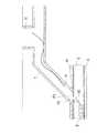
図1は、実施形態1に係るパイロット孔削孔治具1を示す半断面図である。(Embodiment 1)
FIG. 1 is a half sectional view showing a pilot
このパイロット孔削孔治具1は、支持筒部材2と、支持筒部材2の外周面に配設されたパッカー3と、支持筒部材2の内周面にブッシュ21を介して固定された回転機能および摺動機能を備えるベアリング4と、回転機能および摺動機能を備えるベアリング4によって回転自在に、かつ、軸心方向に移動自在に支持されたホールソー5とから構成されている。 The pilot
ここで、パッカー3は、ゴム等を円筒状に形成したものであり、その一端縁部が支持筒部材2の一端面に固定材31を介して挾着されるとともに、他端部が支持筒部材2の他端部外周面に固定バンド32を介して止着されている。これにより、支持筒部材2に形成された流路2aにエア配管6(図2参照)を接続し、図示しないコンプレッサー等の空気源を作動させて圧力空気を供給することにより、両端が固定されたパッカー3を膨張させて拡径させることができる。 Here, the
また、回転機能および摺動機能を備えるベアリング4は、市販品(日本ベアリング株式会社の製造販売に係る商品名:ストロークブッシュ参照)であって、保持器41に多数の鋼球42を回転自在に支持して外筒43内に挿入して構成され、支持筒部材2の内周面にCリングを介して固定されたブッシュ21に外筒43がはめあいにより嵌合されている。これにより、外筒43に対して保持器41が多数の鋼球42に支持されて回転し、かつ、軸心方向に移動することができる。なお、外筒43の前後各端部には、保持器41の抜け出しを防止するストッパ431が設けられている。 The
さらに、ホールソー5は、開口端に周方向に間隔をおいて複数個の超硬チップ刃511を設けた筒状本体51と、シャフト52とを一体に備えて構成されている。ホールソー5は、筒状本体51を支持筒部材2の先端部の外方に突出させた状態で、シャフト52の先端部に筒状本体51が連結されている。シャフト52は、支持筒部材2に固定された回転機能および摺動機能を備えるベアリング4に支持され、シャフト52の後端部にフレキシブルシャフト7が着脱自在に連結される。 Further, the
この場合、詳細には図示しないが、ホールソー5に、その中心に位置して筒状本体51から突出する先導刃としてのドリル刃が設けられてもよい。 In this case, although not shown in detail, the
次に、このように構成されたパイロット孔削孔治具1を用いて既設管Kを更生する更生管Sに取付管Tとの取付管口Kaに連通する接続口Saを形成する削孔方法について、図2〜図6を参照しつつ説明する。 Next, a drilling method for forming a connection port Sa communicating with the mounting tube port Ka with the mounting tube T on the rehabilitated tube S for rehabilitating the existing tube K using the pilot
既設管Kは、その内部において更生管Sが製管され、既設管Kと更生管Sとの間隙にモルタルMが充填され、更生管SおよびモルタルMからなる複合管によって更生されている。既設管Kを更生するための更生管Sとしては、金属製補強材が装着された補強材付き帯状部材を、螺旋状に巻き回すことによって製管された管状体であって、高い自立強度を有するものであってもよい。この場合にも、既設管Kと更生管Sとの間に、モルタルMが間詰め材として充填される。 In the existing pipe K, the rehabilitation pipe S is manufactured, the gap between the existing pipe K and the rehabilitation pipe S is filled with mortar M, and the existing pipe K is rehabilitated by a composite pipe composed of the rehabilitation pipe S and the mortar M. As the rehabilitating pipe S for rehabilitating the existing pipe K, it is a tubular body that is formed by spirally winding a band member with a reinforcing material to which a metal reinforcing material is attached, and has a high self-supporting strength. You may have. Also in this case, the mortar M is filled as a filling material between the existing pipe K and the renovated pipe S.
既設管Kと取付管Tとの取付管口Kaは、図示しない保護部材によって保護された状態でモルタルMが充填される。このため、取付管口Kaは開口されている。ただし、更生管Sを製管する帯状部材のリブ間にモルタルMは回り込むため、リブの高さに略相当する厚みのモルタルMが更生管Sの外周面に積層されている。 The mortar M is filled in the attachment pipe port Ka between the existing pipe K and the attachment pipe T while being protected by a protection member (not shown). For this reason, the attachment pipe port Ka is opened. However, since the mortar M wraps around between the ribs of the belt-shaped member for producing the rehabilitated pipe S, the mortar M having a thickness substantially corresponding to the height of the rib is laminated on the outer peripheral surface of the rehabilitated pipe S.
まず、地上において、パイロット孔削孔治具1の支持筒部材2に先端側からホールソー5のシャフト52を挿通し、回転機能および摺動機能を備えるベアリング4に支持させる。また、シャフト52の後端部にフレキシブルシャフト7を連結し、さらに、支持筒部材2の流路2aにエア配管6を接続した後、パイロット孔削孔治具1をマス91等を通して取付管T内に挿入する(図2参照)。 First, on the ground, the
次いで、TVカメラVによりパイロット孔削孔治具1が設定位置に達したことを確認したならば、エア配管6を通して圧力空気をパッカー3に供給し、パッカー3を膨張させて取付管Tの内周面に密着させ、パイロット孔削孔治具1を取付管Tに支持する。すなわち、パイロット孔削孔治具1のホールソー5の軸心を取付管Tの軸心に一致させてパイロット孔削孔治具1を取付管Tの取付管口Kaの近傍に固定する(図3参照)。なお、TVカメラVは取付管Tから引き上げておく。 Next, when it is confirmed by the TV camera V that the pilot
そして、パイロット孔削孔治具1を取付管Tの取付管口Kaの近傍に固定した状態で、図示しないモータを介してフレキシブルシャフト7を回転させるとともに、押し込むことにより、ホールソー5が回転し、超硬チップ刃511が、既設管Kと取付管Tとの取付管口Kaの中心に略対応する位置の更生管S(外周面に積層されたモルタルMを含む)にホールソー5の筒状本体51の直径に略相当する径のパイロット孔Paを形成する。この際、膨張したパッカー3を介して取付管Tに対して支持筒部材2が固定され、ホールソー5が支持筒部材2に設けられた回転機能および摺動機能を備えるベアリング4によって回転自在に、かつ、軸線方向に移動自在に支持されていることにより、更生管Sが金属製補強材を装着した補強材付き帯状部材を螺旋状に巻き回すことによって製管された場合であっても、ホールソー5を飛び跳ねることなく確実に支持してパイロット孔Paを安定的に形成することができる。 Then, in a state where the pilot
このようにして、既設管Kと取付管Tとの取付管口Kaの中心に略対応して更生管Sにパイロット孔Paを形成したならば、パッカー3に供給された圧力空気をエア配管6を通して排気することにより、パッカー3を縮径させてパイロット孔削孔治具1を取付管Tからマス91等を経て引き出す。 In this way, if the pilot hole Pa is formed in the rehabilitation pipe S substantially corresponding to the center of the attachment pipe port Ka between the existing pipe K and the attachment pipe T, the pressure air supplied to the
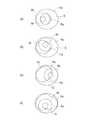
次いで、パイロット孔Paの近傍位置まで取付管T内にTVカメラVを挿入するとともに、中心部に識別マーク8a(図5参照)を有する削孔刃(筒状体の先端部にダイヤモンド粒子を蒸着等によって付着させたもの)81を搭載した削孔装置8をマンホール等から更生管S内に搬入し、パイロット孔Paを臨む位置まで搬送する。そして、更生管Sに形成されたパイロット孔PaをTVカメラVで確認しつつ、削孔装置8の削孔刃81を回転させながら上昇させ、パイロット孔Paの周縁部を周方向に間隔をおいて複数回にわたって切削し、取付管口Kaに連通する接続口Saを形成する。すなわち、更生管Sに形成されたパイロット孔Paは、既設管Kと取付管Tとの取付管口Kaの中心に略対応する位置に形成されていることにより、ホールソー5の筒状本体51の外径よりも若干大きな外径を有する削孔装置8の削孔刃81をパイロット孔Paの周縁に沿って順に移動させて切削することにより、取付管口Kaに連通する接続口Saを更生管Sに効率よく形成することができる。 Next, the TV camera V is inserted into the mounting tube T up to a position near the pilot hole Pa, and a diamond drilling blade having an
具体的には、呼び径150mmの取付管Tが既設管Kに軸心に対して60度の角度で接続されて、短径154mm、長径178mmの楕円状の取付管口Kaの中心に略対応する位置の更生管Sにホールソー5によって直径80mmのパイロット孔Paを形成した。次いで、TVカメラVにより削孔装置8の直径100mmの削孔刃81における直径40mmの識別マーク8aをパイロット孔Paを通して視認しつつ、削孔刃81をパイロット孔Paの周縁部において周方向にほぼ90度の間隔をおいて4回切削することにより、取付管口Kaに連通する接続口Saを更生管Sに形成することができた(図5参照)。 Specifically, a mounting pipe T having a nominal diameter of 150 mm is connected to the existing pipe K at an angle of 60 degrees with respect to the axis, and substantially corresponds to the center of an elliptical mounting pipe port Ka having a short diameter of 154 mm and a long diameter of 178 mm. A pilot hole Pa having a diameter of 80 mm was formed by the
すなわち、短径154mm、長径178mmの楕円状の取付管口Kaの略中心に位置して直径80mmのパイロット孔Paが形成されると、取付管口Kaとパイロット孔Paとの間隔は、長径側において49mm、短径側において37mmとなる。したがって、TVカメラVによってパイロット孔Pa内に削孔刃81の直径40mmの識別マーク8aを視認できるならば、直径100mmの削孔刃81は、パイロット孔Paの周縁から30mmの範囲を切削することから、取付管口Kaを損傷させることを確実に防止して更生管Sに接続口Saを形成することができる。 That is, when the pilot hole Pa having a diameter of 80 mm is formed at the approximate center of the elliptical mounting pipe port Ka having a short diameter of 154 mm and a long diameter of 178 mm, the distance between the mounting pipe port Ka and the pilot hole Pa is 49 mm and 37 mm on the short diameter side. Therefore, if the
なお、削孔刃81によってパイロット孔Paの周縁部を切削した際の残余部分については、削孔刃81の先端部外周面のダイヤモンド粒子によって削り落とすことができる。 The remaining portion when the peripheral edge portion of the pilot hole Pa is cut by the
更生管Sに既設管Kと取付管Tとの取付管口Kaに連通する接続口Saを形成したならば、接続口Saの周縁部を仕上げ加工した後、詳細には図示しないが、更生管Sと同一材料からなるチーズ状補修部材を補修用パッカーを介して接続口Saまで搬送し、補修用パッカーに加熱空気を供給して拡径させ、その首部を接続口Saを通して取付管T内に突出させ、補修部材の首部分を取付管Tの下端部内周面に密着させるとともに、補修部材の胴部分を更生管Sの内周面に密着させる。この際、補修部材は、加熱空気によって加熱されることにより、軟化溶融して取付管Tの下端部内周面および接続口Sa近傍の更生管Sの内周面にそれぞれ密着状態で貼着する。 If the connection port Sa communicating with the attachment tube port Ka of the existing tube K and the attachment tube T is formed in the rehabilitation tube S, the peripheral portion of the connection port Sa is finished and processed. A cheese-like repair member made of the same material as S is conveyed to the connection port Sa through the repair packer, heated air is supplied to the repair packer to expand the diameter, and the neck portion is inserted into the attachment tube T through the connection port Sa. The neck portion of the repair member is brought into close contact with the inner peripheral surface of the lower end portion of the attachment pipe T, and the body portion of the repair member is brought into close contact with the inner peripheral surface of the renovated pipe S. At this time, the repair member is softened and melted by being heated by the heated air, and is adhered to the inner peripheral surface of the lower end portion of the attachment tube T and the inner peripheral surface of the renovated tube S in the vicinity of the connection port Sa.
これにより、取付管Tの下端部が更生管Sと接続口Saを通して補修部材によって補修されて接続される。そして、更生管Sと取付管Tとが補修部材を介して接続されたならば、加熱空気に代えて冷却空気を供給して補修部材を硬化させた後、空気の供給を中止して補修用パッカーを縮径させ、更生管Sを通して引き出せばよい。 Thereby, the lower end part of the attachment pipe T is repaired and connected by the repair member through the rehabilitation pipe S and the connection port Sa. And if the rehabilitation pipe | tube S and the attachment pipe | tube T are connected through the repair member, after supplying cooling air instead of heating air and hardening a repair member, supply of air is stopped and it is for repair. The diameter of the packer may be reduced and pulled out through the rehabilitation pipe S.
(実施形態2)
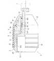
図7は、本発明の実施形態2に係るパイロット孔削孔治具1を示す半断面図である。(Embodiment 2)
FIG. 7 is a half cross-sectional view showing a pilot
この形態に係るパイロット孔削孔治具1は、実施形態1と基本構成において同様であるが、さらに支持筒部材2に収納部23が備えられ、硬質管状体36を介してエア配管が接続される点に特徴を有している。以下では、パイロット孔削孔治具1におけるこれらの特徴部分について詳細に説明し、他の構成については実施形態1と共通の符号を用いて説明を省略する。 The pilot
支持筒部材2の外周面に配設されたパッカー3は、一端部の外周面に固定バンド32が係止されて、支持筒部材2の先端側外周面に固定されている。また、パッカー3の他端部は、支持筒部材2の後端部に固定材33により挾着されて固定されている。固定材33は、支持筒部材2の後端部に一体に取り付けられている。固定材33の外周面は、後端部ほど縮径した円錐台形状に形成され、取付管Tへの挿入抵抗を生じず、スムーズに取付管口Kaの近傍まで到達するように構成されている。 The
また、支持筒部材2は、外周側に開放された環状の凹溝22を有する。この凹溝22は、外周面に備えられたパッカー3の内面との間に、圧縮空気を導入するための空間部を形成している。支持筒部材2の流路2aは、支持筒部材2の後端部を貫通して軸心方向に設けられ、支持筒部材2の凹溝22に連通されている。固定材33にも、支持筒部材2の流路2aと同径の流路34が軸心方向に貫通して設けられている。固定材33は、この流路34を支持筒部材2の流路2aに連続させるように配置され、支持筒部材2の後端部に接続されている。 Moreover, the
固定材33の流路34には、金属製の接続部材35を介して、硬質管状体36が接続される。硬質管状体36は、耐衝撃性を有する硬質の可撓管であり、合成樹脂系複合管や油圧配管用の補強ゴムホース等を好適に利用することができる。硬質管状体36には、圧縮空気を供給するためのエア配管(図9における符号6)が連結される。これにより、エア配管から供給される圧縮空気は、硬質管状体36から、固定材33の流路34と支持筒部材2の流路2aとを経由して凹溝22に到達し、拡散されてパッカー3を膨張させる。 A rigid
また、硬質管状体36は、耐衝撃性を有する硬質の可撓管であることから、軸心方向の外力を固定材33に伝達し得る。そのため、硬質管状体36は、軸心方向の外力を受けて、パイロット孔削孔治具1を取付管Tの奥部へと押し込む作用をなす。すなわち、地上からエア配管を介して硬質管状体36を押し込む操作をすることにより、パイロット孔削孔治具1が挿入方向に押し込まれ、容易に設定位置まで到達させることが可能となる。 In addition, since the hard
例示の形態に係るパイロット孔削孔治具1では、さらに支持筒部材2に収納部23が設けられている。収納部23は、支持筒部材2の先端側に配設されている。また、収納部23は、ホールソー5の筒状本体51の円筒部512に対応して、円筒部512の外径と略同等または円筒部512の外径よりも大きい略円柱状の内部空間を備えて、支持筒部材2の先端方向に開放して形成されている。これにより、図7に示すように、筒状本体51は、支持筒部材2の収納部23の内側に収められている。 In the pilot
前述のとおり、ホールソー5は、支持筒部材2の内周面に固定されたベアリング4によって、支持筒部材2の内側で回転自在に、かつ、軸心方向に移動自在に支持されている。そのため、ホールソー5のシャフト52の軸心方向の移動にともなって、筒状本体51は支持筒部材2の収納部23から出没自在とされている。すなわち、シャフト52がベアリング4を介して支持筒部材2の先端方向に移動することで、筒状本体51は収納部23から突出する。また、シャフト52が支持筒部材2の後端方向に移動することで、筒状本体51は収納部23の内側に収納される。 As described above, the
これにより、ホールソー5の筒状本体51が収納された状態のとき、パイロット孔削孔治具1は全体として極めてコンパクトに形成され、狭い管路であっても容易に挿入することが可能とされる。また、パイロット孔削孔治具1を設定位置まで挿入して、パイロット孔Paを削孔する際には、筒状本体51を支持筒部材2の先端から突出させて使用することができる。 Thereby, when the cylindrical
図8は、パイロット孔削孔治具1の変形例を示す半断面図である。このパイロット孔削孔治具1は、図示するように、ホールソー5として、図7とは大きさの異なる筒状本体51を備えている。この筒状本体51は、図7に示した筒状本体51と同等の外径を有する一方、円筒部512が軸心方向に長く延設して形成されている。この場合、かかる筒状本体51に対応して、支持筒部材2の収納部23も図7に示す形態よりも軸心方向に拡張された略円柱状の内部空間を有して形成されている。 FIG. 8 is a half sectional view showing a modification of the pilot
これにより、図8に示すパイロット孔削孔治具1は、より大きな筒状本体51を有するものの、図7に示したパイロット孔削孔治具1と同等の外形状を保持し、全体として極めてコンパクトに形成することができる。加えて、筒状本体51が支持筒部材2の収納部23から突出すると、支持筒部材2からの筒状本体51の突出量は図7に示した形態よりも大きく確保することができる。したがって、回転する筒状本体51の超硬チップ刃511を、支持筒部材2から、より遠くに到達させることができ、多様な管路に対応させて良好にパイロット孔Paを削孔することが可能となる。 Thereby, although the pilot
図9は、実施形態2に係るパイロット孔削孔治具1を用いて行うパイロット孔Paの削孔方法の一工程を示す説明図である。 FIG. 9 is an explanatory view showing one step of a pilot hole Pa drilling method performed using the pilot
実施形態2に係るパイロット孔削孔治具1は、図2に示されるような管路を挿通させてパイロット孔Paを形成する場合だけでなく、さらに図9に例示するような管路にあっても好適に使用することができる。 The pilot
すなわち、図9に示す管路は、マス91が比較的小型のサイズである立上り管(例えば、φ200mm)により形成され、マス91より小径の横引き管92(例えば、φ150mm)に接続されている。横引き管92には、取付管Tが接続され、取付管Tの下流端が下水道本管である既設管Kに接続されている。既設管Kは、更生管Sにより更生され、既設管Kと更生管Sとの間にモルタルMが充填されている。 That is, the pipe shown in FIG. 9 is formed of a rising pipe (for example, φ200 mm) in which the
小型のマス91と横引き管92とは、互いに直交するように接続され、管路が90°曲がっている。このように、小口径であって比較的狭い曲がり部を有する管路に対しても、実施形態2に示すパイロット孔削孔治具1はコンパクトに形成されているので、曲がり部をスムーズに挿通させて、取付管Tへ挿入することができる。 The
パイロット孔削孔治具1には、シャフト52の後端部にフレキシブルシャフト7を連結し、支持筒部材2の流路2aに接続した硬質管状体36にエア配管6を連結する。硬質管状体36の長さは特に限定されるものではないが、図9に示すような管路の場合、例えば30cmの長さを有するゴムホース等の硬質管状体36を支持筒部材2の流路2aに連結する。さらに、この硬質管状体36に、配管延長に対応する長さを有する耐衝撃性硬質塩化ビニル管からなるエア配管6を連結する。 In the pilot
かかるパイロット孔削孔治具1を、図9に示すように、地上からマス91を通して、横引き管92、さらには取付管Tへと挿入していく。ホールソー5の筒状本体51は、支持筒部材2の内側の収納部23に収納されている。この間、エア配管6に接続された硬質管状体36を介して、地上からパイロット孔削孔治具1の向きを操作し、軸心方向に押し込む。これにより、押込み力が硬質管状体36を介して固定材33に伝達され、小口径の狭い曲がり部においても、パイロット孔削孔治具1をスムーズに挿通させて、管路の奥部へと容易に挿入することができる。 As shown in FIG. 9, the pilot
TVカメラVにより確認しながら、パイロット孔削孔治具1が設定位置に達したことを確認したならば、エア配管6を通して圧力空気をパッカー3の内側へ供給し、パッカー3を膨張させる。これにより、パイロット孔削孔治具1を取付管Tの内周面に密着させ、取付管Tに固定することができる(図3参照)。パイロット孔削孔治具1は、ホールソー5の軸心を取付管Tの軸心に一致させて、取付管Tの取付管口Kaの近傍に固定される。 If it is confirmed by the TV camera V that the pilot
次いで、モータを駆動してフレキシブルシャフト7を回転させるとともに、押し込むことにより、ホールソー5を回転させ、支持筒部材2の先端方向へ移動させる。ホールソー5の筒状本体51は、支持筒部材2の先端部から押し出される。筒状本体51の先端部の超硬チップ刃511は、その回転によって、更生管Sにパイロット孔Paを形成する。パイロット孔Paは、既設管Kと取付管Tとの取付管口Kaの中心に略対応する位置の更生管Sに、筒状本体51の直径に略相当する径の開口として形成される。 Next, the motor is driven to rotate the
パイロット孔削孔治具1としては、既設管Kと取付管Tとの接続角度に応じて、図7または図8に示すように、好ましい大きさの筒状本体51を備えたものを選択して使用することで、多様な管路に対応させて、良好にパイロット孔Paを形成することができる。 As the pilot
パイロット孔Paを形成したならば、パッカー3を縮径させてパイロット孔削孔治具1を地上まで引き上げる。その後、図4〜図6に示した工程と同様に、更生管Sの内側からパイロット孔Paの周縁部を切削し、取付管口Kaに連通する接続口Saを形成する。パイロット孔Paは、既設管Kと取付管Tとの取付管口Kaの中心に略対応する位置に形成されているので、このパイロット孔Paを目安にして、接続口Saを更生管Sに効率よく形成することができる。 If the pilot hole Pa is formed, the diameter of the
以上説明したように、本発明に係るパイロット孔削孔治具1は、従来の問題点を解消して、多様な管路に対応させて用いることができ、補強材付きの帯状部材によって製管された更生管Sに対しても、既設管Kと取付管Tとの取付管口Kaの略中心に位置するパイロット孔Paを確実かつ容易に形成することを可能にする。また、パイロット孔削孔治具1によって形成されたパイロット孔Paに基づいて、更生管Sには、取付管口Kaに連通する接続口Saを極めて効率よく形成することが可能となる。 As described above, the pilot
1 パイロット孔削孔治具
2 支持筒部材
21 ブッシュ
23 収納部
3 パッカー
31 固定材
32 固定バンド
36 硬質管状体
4 回転機能および摺動機能を備えるベアリング
41 保持器
42 鋼球
43 外筒
431 ストッパ
5 ホールソー
51 筒状本体
511 超硬チップ刃
512 円筒部
52 シャフト
6 エア配管
7 フレキシブルシャフト
8 削孔装置
8a 識別マーク
81 削孔刃
K 既設管
Ka 取付管口
Pa パイロット孔
S 更生管
Sa 接続口
T 取付管DESCRIPTION OF
Claims (4)
Translated fromJapanese外周面にパッカーを設けるとともに、内周面に回転機能および摺動機能を備えるベアリングを設けた支持筒部材と、
切削刃を設けた筒状本体および筒状本体に連結されたシャフトを有するホールソーとを備え、
前記ホールソーは、前記シャフトが、前記支持筒部材にベアリングを介して回転自在に、かつ軸心方向に移動自在に支持されるとともに、このシャフトにフレキシブルシャフトが連結可能に形成されており、
前記パッカーの内側に圧力空気が供給されてパッカーが膨張し、このパッカーを介して取付管に対して取付管の軸心とホールソーの軸心とを一致させてホールソーを支持するとともに、前記ホールソーを回転させながら軸心方向に押し込んで該ホールソーを取付管口の略中心に位置させて、更生管にパイロット孔を形成することを特徴とするパイロット孔削孔治具。A pilot hole drilling jig that forms a pilot hole corresponding to the mounting pipe port of the existing pipe and the mounting pipe to the rehabilitation pipe renewed from the existing pipe to which the mounting pipe is connected,
A support cylinder member provided with a bearing provided with a rotation function and a sliding function on the inner peripheral surface while providing a packer on the outer peripheral surface;
A cylindrical main body provided with a cutting blade and a hole saw having a shaft connected to the cylindrical main body,
The hole saw is formed so that the shaft is rotatably supported by the support cylinder member via a bearing and movable in the axial direction, and a flexible shaft can be connected to the shaft.
Pressure air is supplied to the inside of the packer so that the packer expands, and the hole saw is supported with the hole tube by aligning the axis of the mounting tube with the axis of the hole saw with respect to the mounting tube. A pilot hole drilling jig characterized in that a pilot hole is formed in a rehabilitation pipe by pushing in the axial direction while rotating and positioning the hole saw at a substantially center of the mounting pipe opening.
前記支持筒部材は、前記筒状本体を内側に収納しうる収納部を備え、
前記シャフトが軸心方向に移動することにより、該筒状本体が前記支持筒部材の収納部から出没自在とされたことを特徴とするパイロット孔削孔治具。In the pilot drilling jig according to claim 1,
The support cylinder member includes a storage portion that can store the cylindrical main body inside,
A pilot hole drilling jig according to claim 1, wherein the cylindrical main body is allowed to protrude and retract from a housing portion of the support cylinder member by moving the shaft in an axial direction.
前記支持筒部材は、パッカーの内側に連通する流路を備え、この流路には、パッカーを膨張させる圧力空気の供給配管が、耐衝撃性を有する硬質管状体を介して接続されたことを特徴とするパイロット孔削孔治具。In the pilot hole drilling jig according to claim 1 or 2,
The support cylinder member includes a flow path communicating with the inside of the packer, and a supply pipe for pressurized air for expanding the packer is connected to the flow path through a hard tubular body having impact resistance. A pilot drilling jig.
請求項1〜3のいずれか一つの請求項に記載のパイロット孔削孔治具を、地上側から取付管内に挿入し、支持した後、ホールソーを回転させながら押し込んで更生管にパイロット孔を形成し、
次いで、中心部に識別マークを有する削孔刃を搭載した削孔装置を更生管からパイロット孔を臨む位置まで搬送し、パイロット孔を通して削孔刃の識別マークを視認した状態で削孔刃を介してパイロット孔の周縁部を複数回削孔し、更生管に取付管口に連通する接続口を形成することを特徴とする更生管の接続口削孔方法。A connection hole drilling method for forming a connection port in communication with the attachment pipe port of the existing pipe and the attachment pipe to the rehabilitation pipe renewed from the existing pipe to which the attachment pipe is connected,
The pilot hole drilling jig according to any one of claims 1 to 3 is inserted into the attachment pipe from the ground side and supported, and then the hole saw is pushed in while rotating to form a pilot hole in the rehabilitation pipe. And
Next, a drilling device equipped with a drilling blade having an identification mark in the center is conveyed from the rehabilitation pipe to the position facing the pilot hole, and the drilling blade identification mark is visually confirmed through the pilot hole. A connection hole drilling method for a rehabilitation pipe, wherein the peripheral edge of the pilot hole is drilled a plurality of times to form a connection port in the rehabilitation pipe that communicates with the mounting pipe port.
Priority Applications (1)
| Application Number | Priority Date | Filing Date | Title |
|---|---|---|---|
| JP2014122162AJP6313668B2 (en) | 2013-06-14 | 2014-06-13 | Pilot hole drilling jig and rehabilitation pipe connection hole drilling method |
Applications Claiming Priority (3)
| Application Number | Priority Date | Filing Date | Title |
|---|---|---|---|
| JP2013125623 | 2013-06-14 | ||
| JP2013125623 | 2013-06-14 | ||
| JP2014122162AJP6313668B2 (en) | 2013-06-14 | 2014-06-13 | Pilot hole drilling jig and rehabilitation pipe connection hole drilling method |
Publications (2)
| Publication Number | Publication Date |
|---|---|
| JP2015016545Atrue JP2015016545A (en) | 2015-01-29 |
| JP6313668B2 JP6313668B2 (en) | 2018-04-18 |
Family
ID=52438065
Family Applications (1)
| Application Number | Title | Priority Date | Filing Date |
|---|---|---|---|
| JP2014122162AExpired - Fee RelatedJP6313668B2 (en) | 2013-06-14 | 2014-06-13 | Pilot hole drilling jig and rehabilitation pipe connection hole drilling method |
Country Status (1)
| Country | Link |
|---|---|
| JP (1) | JP6313668B2 (en) |
Cited By (1)
| Publication number | Priority date | Publication date | Assignee | Title |
|---|---|---|---|---|
| CN110449651A (en)* | 2019-06-25 | 2019-11-15 | 浙江尚品店配信息科技有限公司 | A kind of guillotine for clothes showing shelf crossbeam |
Citations (7)
| Publication number | Priority date | Publication date | Assignee | Title |
|---|---|---|---|---|
| JPS6483995A (en)* | 1987-09-26 | 1989-03-29 | Osaka Gas Co Ltd | Bag for interrupting fluid condit |
| JPH0871820A (en)* | 1994-09-02 | 1996-03-19 | Koji Hagino | Pipeline intersecting part sealant boring method and device therefor |
| JPH0881995A (en)* | 1994-09-09 | 1996-03-26 | Nagasaki Jutaku Setsubi:Kk | Borer for repairing material |
| JP2004509328A (en)* | 2000-09-13 | 2004-03-25 | ビ−エイイ− システムズ パブリック リミテッド カンパニ− | Measuring method |
| JP2004216487A (en)* | 2003-01-14 | 2004-08-05 | Ootekku Kogyo:Kk | Main pipe lining material perforating device at branch portion for branch pipe |
| JP2006289597A (en)* | 2005-04-15 | 2006-10-26 | Shonan Plastic Mfg Co Ltd | Drilling device |
| JP2012254518A (en)* | 2011-05-16 | 2012-12-27 | Seiko Epson Corp | Robot control system, robot system and program |
- 2014
- 2014-06-13JPJP2014122162Apatent/JP6313668B2/ennot_activeExpired - Fee Related
Patent Citations (7)
| Publication number | Priority date | Publication date | Assignee | Title |
|---|---|---|---|---|
| JPS6483995A (en)* | 1987-09-26 | 1989-03-29 | Osaka Gas Co Ltd | Bag for interrupting fluid condit |
| JPH0871820A (en)* | 1994-09-02 | 1996-03-19 | Koji Hagino | Pipeline intersecting part sealant boring method and device therefor |
| JPH0881995A (en)* | 1994-09-09 | 1996-03-26 | Nagasaki Jutaku Setsubi:Kk | Borer for repairing material |
| JP2004509328A (en)* | 2000-09-13 | 2004-03-25 | ビ−エイイ− システムズ パブリック リミテッド カンパニ− | Measuring method |
| JP2004216487A (en)* | 2003-01-14 | 2004-08-05 | Ootekku Kogyo:Kk | Main pipe lining material perforating device at branch portion for branch pipe |
| JP2006289597A (en)* | 2005-04-15 | 2006-10-26 | Shonan Plastic Mfg Co Ltd | Drilling device |
| JP2012254518A (en)* | 2011-05-16 | 2012-12-27 | Seiko Epson Corp | Robot control system, robot system and program |
Cited By (2)
| Publication number | Priority date | Publication date | Assignee | Title |
|---|---|---|---|---|
| CN110449651A (en)* | 2019-06-25 | 2019-11-15 | 浙江尚品店配信息科技有限公司 | A kind of guillotine for clothes showing shelf crossbeam |
| CN110449651B (en)* | 2019-06-25 | 2020-07-07 | 浙江尚品店配信息科技有限公司 | A guillootine for clothing show shelf crossbeam |
Also Published As
| Publication number | Publication date |
|---|---|
| JP6313668B2 (en) | 2018-04-18 |
Similar Documents
| Publication | Publication Date | Title |
|---|---|---|
| CN110056741B (en) | Repairing device and repairing method for CIPP pipeline | |
| EP2844905B1 (en) | Liner assembly for pipeline repair or reinforcement and method of installing same | |
| KR19990068142A (en) | Pipe lining method | |
| JP5822910B2 (en) | Method for operating a horizontal drilling device and horizontal drilling device | |
| US8083010B2 (en) | Drilling device for drilling and reaming of a hole | |
| KR101164925B1 (en) | System and method for pipeline renovation | |
| JP6313668B2 (en) | Pilot hole drilling jig and rehabilitation pipe connection hole drilling method | |
| JP5808389B2 (en) | Horizontal drilling device | |
| JP2010070971A (en) | Method for pulling out lining material after construction | |
| JP6267040B2 (en) | Drilling device | |
| JP5485810B2 (en) | Injection method and equipment | |
| KR101957438B1 (en) | Drilling bit with extensible casing and non-welding coupler and tunnel construction method for extended cutting pipe therewith | |
| WO1990010173A1 (en) | Improvements relating to the lining of pipelines or passageways | |
| JP7279877B2 (en) | Drilling device and drilling method | |
| US10427223B2 (en) | Device for opening connection to lined pipe | |
| US9290993B2 (en) | Method and system for installation of in-ground conduit | |
| JP2008286272A (en) | Regeneration pipe and method for regenerating pipeline | |
| US20200087989A1 (en) | Hydro boring systems and methods | |
| JP4787530B2 (en) | Drilling device | |
| JP2008164060A (en) | Manufactured pipe for forming pipeline | |
| JP3561449B2 (en) | Method and apparatus for enlarging cutting of existing pipeline | |
| US10969051B2 (en) | Top hat liner having integrated thermoplastic with improved melt-flow characteristics for connection of main and lateral pipes in cured in place pipe systems and associated method of use | |
| JP5909207B2 (en) | Underground pipe rehabilitation pipe material | |
| JP3963465B2 (en) | Installation pipe restoration method and device when renewing main pipe buried underground | |
| US8684104B1 (en) | Detachable pipe ramming head with efficient lubrication dispersal |
Legal Events
| Date | Code | Title | Description |
|---|---|---|---|
| A621 | Written request for application examination | Free format text:JAPANESE INTERMEDIATE CODE: A621 Effective date:20170118 | |
| A131 | Notification of reasons for refusal | Free format text:JAPANESE INTERMEDIATE CODE: A131 Effective date:20171031 | |
| A977 | Report on retrieval | Free format text:JAPANESE INTERMEDIATE CODE: A971007 Effective date:20171031 | |
| A521 | Request for written amendment filed | Free format text:JAPANESE INTERMEDIATE CODE: A523 Effective date:20171226 | |
| TRDD | Decision of grant or rejection written | ||
| A01 | Written decision to grant a patent or to grant a registration (utility model) | Free format text:JAPANESE INTERMEDIATE CODE: A01 Effective date:20180227 | |
| A61 | First payment of annual fees (during grant procedure) | Free format text:JAPANESE INTERMEDIATE CODE: A61 Effective date:20180323 | |
| R151 | Written notification of patent or utility model registration | Ref document number:6313668 Country of ref document:JP Free format text:JAPANESE INTERMEDIATE CODE: R151 | |
| LAPS | Cancellation because of no payment of annual fees |