JP2015016095A - Osteotomy operation instrument - Google Patents
Osteotomy operation instrumentDownload PDFInfo
- Publication number
- JP2015016095A JP2015016095AJP2013144777AJP2013144777AJP2015016095AJP 2015016095 AJP2015016095 AJP 2015016095AJP 2013144777 AJP2013144777 AJP 2013144777AJP 2013144777 AJP2013144777 AJP 2013144777AJP 2015016095 AJP2015016095 AJP 2015016095A
- Authority
- JP
- Japan
- Prior art keywords
- osteotomy
- blade
- guard
- surgical instrument
- main body
- Prior art date
- Legal status (The legal status is an assumption and is not a legal conclusion. Google has not performed a legal analysis and makes no representation as to the accuracy of the status listed.)
- Granted
Links
- 210000000988bone and boneAnatomy0.000claimsabstractdescription39
- 239000000463materialSubstances0.000claimsdescription7
- 230000035515penetrationEffects0.000claimsdescription4
- 230000035699permeabilityEffects0.000claimsdescription2
- 210000004872soft tissueAnatomy0.000abstractdescription28
- 230000000452restraining effectEffects0.000abstract1
- 210000002303tibiaAnatomy0.000description33
- 230000004048modificationEffects0.000description8
- 238000012986modificationMethods0.000description8
- 210000001519tissueAnatomy0.000description8
- 238000000034methodMethods0.000description4
- 238000007796conventional methodMethods0.000description3
- 229910052751metalInorganic materials0.000description3
- 239000002184metalSubstances0.000description3
- 229920005989resinPolymers0.000description3
- 239000011347resinSubstances0.000description3
- 102000008186CollagenHuman genes0.000description2
- 108010035532CollagenProteins0.000description2
- 208000003947Knee OsteoarthritisDiseases0.000description2
- 239000004696Poly ether ether ketoneSubstances0.000description2
- 239000004734Polyphenylene sulfideSubstances0.000description2
- 210000004204blood vesselAnatomy0.000description2
- 238000006243chemical reactionMethods0.000description2
- 229920001436collagenPolymers0.000description2
- 210000003127kneeAnatomy0.000description2
- 210000000629knee jointAnatomy0.000description2
- 210000003205muscleAnatomy0.000description2
- 229920002530polyetherether ketonePolymers0.000description2
- 229920000069polyphenylene sulfidePolymers0.000description2
- 238000001356surgical procedureMethods0.000description2
- YCKRFDGAMUMZLT-UHFFFAOYSA-NFluorine atomChemical compound[F]YCKRFDGAMUMZLT-UHFFFAOYSA-N0.000description1
- RTAQQCXQSZGOHL-UHFFFAOYSA-NTitaniumChemical compound[Ti]RTAQQCXQSZGOHL-UHFFFAOYSA-N0.000description1
- 241000469816VarusSpecies0.000description1
- 230000003187abdominal effectEffects0.000description1
- 230000009471actionEffects0.000description1
- 230000015572biosynthetic processEffects0.000description1
- 239000000470constituentSubstances0.000description1
- 230000001276controlling effectEffects0.000description1
- 238000010586diagramMethods0.000description1
- 238000006073displacement reactionMethods0.000description1
- 230000001747exhibiting effectEffects0.000description1
- 229910052731fluorineInorganic materials0.000description1
- 239000011737fluorineSubstances0.000description1
- 210000003041ligamentAnatomy0.000description1
- 230000007246mechanismEffects0.000description1
- 201000008482osteoarthritisDiseases0.000description1
- 210000004417patellaAnatomy0.000description1
- 230000001105regulatory effectEffects0.000description1
- 229910001220stainless steelInorganic materials0.000description1
- 239000010935stainless steelSubstances0.000description1
- 239000010936titaniumSubstances0.000description1
- 229910052719titaniumInorganic materials0.000description1
Images


Landscapes
- Surgical Instruments (AREA)
Abstract
Description
Translated fromJapanese本発明は、骨切り用手術器械、より詳しくは、変形性膝関節症等に使用される骨切り用手術器械に関する。 The present invention relates to a surgical instrument for osteotomy, and more particularly to a surgical instrument for osteotomy used for osteoarthritis of the knee.
従来、変形性膝関節症(膝OA)に対し、高位脛骨骨切り術(HTO)が行われている。これは、内反変形を呈した脛骨近位部において、これを矯正してアライメントを整え、膝の内側関節に偏った荷重の多くを外側関節に移動する手術である。 Conventionally, high tibial osteotomy (HTO) has been performed for knee osteoarthritis (knee OA). This is an operation in which the proximal part of the tibia exhibiting varus deformity is corrected and aligned to move most of the load biased to the inner joint of the knee to the outer joint.
HTOは、外側開きのくさび型骨片を脛骨から切り取るlateral closed wedge (CWHTO)と、脛骨の内側に形成した切込みをノミ等により開大するmedial open wedge (OWHTO)の大きく二つに分類できる。いずれの術式においても、脛骨に対して水平方向に切込みを入れるために、骨切り用手術器械が用いられる。 The HTO can be roughly classified into two types: a lateral closed wedge (CWHTO) that cuts a wedge-shaped bone piece that opens outward from the tibia, and a medial open wedge (OWHTO) that opens the cut formed inside the tibia with a chisel or the like. In any of the surgical procedures, an osteotomy surgical instrument is used to make an incision in the horizontal direction with respect to the tibia.
特許文献1には、骨切り用手術器械の一例が記載されている。この骨切り用手術器械は、骨ノミ等とも呼ばれ、一方の端部に骨切り刃が、他方の端部にハンマーを打つための被叩打部が設けられている。骨切り刃の刃先を骨にあてがい、被叩打部をハンマー等で打つことにより、骨切り刃で骨を切り進めることができる。
HTOでは、脛骨に略水平に切込みを入れるが、特許文献1に記載のような骨切り用手術器械を用いて切込みを入れる場合は、特に骨の背側に切込みを入れる際に細心の注意を払う必要がある。骨の背側には、血管や筋肉などの軟組織が存在するため、骨切り刃が軟組織にあたると、軟組織を傷めることにより患者の負担が増加する可能性があるからである。
したがって、骨の周囲に存在する軟組織への影響を抑えつつ骨に切込みを入れることができる骨切り用手術器械の登場が望まれている。In HTO, incision is made in the tibia approximately horizontally, but when making an incision using a surgical instrument for osteotomy as described in
Therefore, the appearance of a surgical instrument for osteotomy that can cut into the bone while suppressing the influence on the soft tissue existing around the bone is desired.
本発明は、上記事情に鑑みてなされたものであって、骨の周囲に存在する軟組織への影響を抑えつつ骨に切込みを入れることができる骨切り用手術器械を提供することを目的とする。 The present invention has been made in view of the above circumstances, and an object of the present invention is to provide a surgical instrument for osteotomy that can cut into a bone while suppressing an influence on soft tissue existing around the bone. .
本発明は、骨組織を切る骨切り刃と、前記骨切り刃を側面から見たときに、少なくとも前記骨切り刃の刃先と重なるように配置されたガードとを備える骨切り用手術器械である。 The present invention is a surgical instrument for osteotomy comprising an osteotomy blade for cutting bone tissue and a guard arranged so as to overlap at least the cutting edge of the osteotomy blade when the osteotomy blade is viewed from the side. .
前記ガードは、前記骨切り刃の刃先よりも前方に突出するように配置されてもよい。
また、前記ガードは、前記刃先の位置に対応して形成された指標部を有してもよい。
さらに、前記ガードは、前記骨切り刃よりもX線透過性の高い材料で形成されてもよいThe guard may be arranged to protrude forward from the cutting edge of the osteotomy blade.
The guard may have an indicator portion formed corresponding to the position of the cutting edge.
Furthermore, the guard may be formed of a material having a higher X-ray permeability than the osteotomy blade.
前記骨切り刃は、板状の本体部の先端部に設けられており、前記本体部は、長手方向中間部に、前記本体部の他の部位に対して変位されたクランク部を有してもよい。 The osteotomy blade is provided at a distal end portion of a plate-like main body portion, and the main body portion has a crank portion that is displaced with respect to other parts of the main body portion at a longitudinal intermediate portion. Also good.
本発明の骨切り用手術器械は、前記本体部から突出して設けられ、前記骨切り刃の生体に対する進入深さを所定量以下に規制するストッパ部をさらに備えてもよい。 The surgical instrument for osteotomy of the present invention may further include a stopper portion that protrudes from the main body portion and restricts the depth of penetration of the osteotomy blade into the living body to a predetermined amount or less.
前記ガードの外面は、曲面状に形成されてもよい。 The outer surface of the guard may be formed in a curved surface shape.
本発明の骨切り用手術器械によれば、骨の周囲に存在する軟組織への影響を抑えつつ骨に切込みを入れることができる。 According to the surgical instrument for osteotomy of the present invention, it is possible to make an incision in the bone while suppressing the influence on the soft tissue existing around the bone.
本発明の第一実施形態について、図1から図3を参照して説明する。
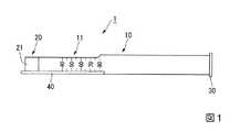
図1は、本実施形態の骨切り用手術器械(以下、単に「手術器械」と称する。)1の全体構成を示す平面図である。手術器械1は、板状の本体部10と、本体部10の第一の端部に設けられ、骨組織を切る骨切り刃20と、本体部10の第二の端部に設けられた被叩打部30と、骨切り刃20に取り付けられたガード40とを備えている。A first embodiment of the present invention will be described with reference to FIGS. 1 to 3.
FIG. 1 is a plan view showing an overall configuration of a surgical instrument for osteotomy (hereinafter simply referred to as “surgical instrument”) 1 of the present embodiment. The
本体部10は、生体適合性を有する金属、例えばステンレス鋼やチタン等からなり、長手方向に延びる板状に形成されている。本体部10の形状には特に制限はないが、本体部のうち、骨切り刃20側は、手技中に一定の長さ組織内に進入するため、板状等の比較的薄い形状の方が、進入の際の抵抗が少なくなり、好ましい。
なお、本発明では、本体部および骨切り刃において、厚さ方向両側にある相対的に大きい一対の側面を上面および下面とし、上面と下面との間に位置する相対的に小さい一対の面を側面と定義する。The
In the present invention, in the main body portion and the osteotomy blade, a relatively large pair of side surfaces on both sides in the thickness direction are defined as an upper surface and a lower surface, and a relatively small pair of surfaces positioned between the upper surface and the lower surface Defined as side.
骨切り刃20は、本体部10から離間するにつれて徐々に薄くなるように形成されており、本体部10から最も遠い先端が、最も薄い刃先21となっている。刃先21の形成方法に制限はなく、厚さ方向の片側のみに斜面が形成される、いわゆる片刃でも、厚さ方向の両側に斜面が形成される、いわゆる両刃でも、いずれでも構わない。本実施形態では、本体部10および骨切り刃20は、同一の材料を用いて一体に形成されている。
本体部10の外面には、刃先21からの距離を示す目盛11が設けられているため、刃先21が組織内に進入して視認できなくなっても、目盛11を頼りに刃先の大まかな位置を把握することができる。The
Since the
被叩打部30は、厚さ方向が本体部10の長手方向と平行(略平行を含む)となるように本体部10に取り付けられており、厚さ方向両側の面が、略正方形に形成されている。被叩打部30は、厚さ方向の面積がハンマー等で叩くのに好適な程度の大きさであれば、その形状に特に制限はない。例えば、厚さ方向両側の面が円形や楕円形であってもよいし、本体部において、骨切り刃が設けられているのと反対側の基端部の厚さあるいは径を大きくすることで本体部と一体の被叩打部が形成されてもよい。
また、被叩打部30の材質も、ハンマー等の衝撃に耐えうる剛性を有していれば、特に制限はなく、本体部10の材質と同一でも異なってもいずれでも構わない。The
Moreover, the material of the hit | damaged
図2は、手術器械1の先端側を示す拡大斜視図である。本実施形態のガード40は、本体部10と同一の材料で形成されており、図2に示すように、刃先21を含む骨切り刃20の左側面を覆うように取り付けられている。ガード40の基本形状は長円形の板状であり、本体部10の面方向とガード40の面方向とが直交(略直交を含む)するように骨切り刃20に取り付けられている。
ガード40の幅寸法D1は、本体部10および骨切り刃20の厚さよりも大きく、ガード40は骨切り刃20の厚さ方向両側に突出している。また、ガード40の先端40Aは、刃先21よりも前方に突出している。ガード40は板状ではあるが、角部および稜線が丸められており、接触した組織に対して過剰な圧力を与えない表面形状を有する。FIG. 2 is an enlarged perspective view showing the distal end side of the
The width dimension D1 of the
上記のように構成された手術器械1の使用時の動作について、HTOにおいて脛骨の背側に切込みを形成する手技を例にとり説明する。
術者は、脛骨近位内側の皮膚および組織を切開し、手術器械1の先端側を挿入して、刃先21を脛骨に接触させる。このとき、ガード40の先端が、脛骨と、筋肉、血管等の軟組織との間に進入するようにする。この状態で、被叩打部30をハンマー等で打つと、骨切り刃20が脛骨に打入され、脛骨に切込みを形成することができる。The operation at the time of use of the
The surgeon incises the skin and tissue inside the proximal tibia and inserts the distal end side of the
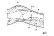
図3に、膝関節周辺における各組織の位置関係を模式的に示すが、図を見やすくするために腓骨は省略している。図3において、膝蓋骨Ptのある上側が腹側、反対の下側が背側である。図3に示すように、脛骨Tbの背側には、軟組織Stが存在しており、ハンマー等の衝撃で刃先21が背側にそれると、軟組織Stを傷める可能性がある。 FIG. 3 schematically shows the positional relationship of each tissue around the knee joint, but the ribs are omitted for easy understanding of the drawing. In FIG. 3, the upper side with the patella Pt is the abdominal side, and the lower side opposite is the dorsal side. As shown in FIG. 3, the soft tissue St exists on the back side of the tibia Tb, and the soft tissue St may be damaged if the
本実施形態の手術器械1では、骨切り刃20にガード40が取り付けられているため、ガード40が脛骨Tbと軟組織Stとの間に進入するようにして脛骨Tbに打入すると、図3に示すように骨切り刃20近傍の軟組織Stがガード40により好適に保護される。万一ハンマー等の衝撃により刃先21が軟組織St側に向いた場合も、ガード40により軟組織Stが脛骨Tbから離間するように圧排され、刃先21が軟組織Stに接触しにくい。 In the
以上説明したように、本実施形態の手術器械1は、ガード40を備えることにより、細心の注意が要求される脛骨背側の骨切りを、骨の周囲に存在する軟組織への影響を抑えつつ好適に行うことができる。
また、従来、HTOでは、軟組織を保護するために、金属製のリトラクター等を用いて軟組織を脛骨から引き離しつつ骨切りが行われているが、手術器械1はリトラクターとしても機能するガード40を備えているため、手術器械とリトラクターとを通常別の人間が操作する従来の手技と異なり、一人で骨切りを行うことも可能になる。As described above, the
Conventionally, in HTO, in order to protect soft tissue, osteotomy is performed using a metal retractor or the like while separating the soft tissue from the tibia, but the
本発明の第二実施形態について、図4から図11を参照して説明する。本実施形態と第一実施形態との異なる点は、本体部の形状およびガードの態様等である。なお、以降の説明において、既に説明したものと共通する構成については、同一の符号を付して重複する説明を省略する。 A second embodiment of the present invention will be described with reference to FIGS. The differences between the present embodiment and the first embodiment are the shape of the main body, the mode of the guard, and the like. In the following description, components that are the same as those already described are assigned the same reference numerals and redundant description is omitted.
図4は、本実施形態の手術器械51を示す斜視図である。手術器械51の本体部10は、長手方向中間部が一定の長さ(例えば40から80mm)にわたり幅方向の一方(本実施形態では右側)に変位しており、クランク部12が形成されている。クランク部12の形状や最大変位量(本体部の他の部位との最大距離)等は、適宜設定することができるが、後述する作用を考慮すると、10mmから30mm程度が好ましい。 FIG. 4 is a perspective view showing the
本実施形態のクランク部12は、本体部10の他の部位と略平行に形成されている。クランク部12には、本体部10と略平行に延びる長穴12aが形成されている。
クランク部12には、手術器械51の生体内への進入量を制御するためのストッパ部60が設けられている。ストッパ部60は、クランク部12に取り付けられるプレート61と、プレート61およびクランク部を貫通するように配置される止めネジ62とを有する。The
The
プレート61は、長穴12aと略同形同大の長穴61aを有し、長穴12aと長穴61aとが手術器械51の平面視に置いて重なるようにクランク部12に固定されている。
止めネジ62は、ねじ溝が切られたネジ部(不図示)と、ネジ部の一方の端部に設けられたツマミ部63とを有する。ネジ部の径は、長穴12aおよび長穴61aの幅よりも小さいため、ネジ部は長穴12aおよび61a内で自由に移動できる。ツマミ部63は長穴12aおよび長穴61aの幅よりも大きい径の円柱状に形成されており、長穴12aおよび長穴61a内には進入できない。
止めネジ62は、ネジ部を長穴12aおよび長穴61aに挿通し、突出したネジ部の端部に図示しない固定ネジを螺合させて締め込むことにより、長穴12aおよび長穴61aに対して任意の位置に位置決めすることができる。The
The
The
図5は、手術器械51の骨切り刃20周辺を右側面側から見た部分拡大図であり、図6は、骨切り刃20周辺を上側から見た部分拡大図である。本実施形態のガード70は、図5および図6に示すように、幅寸法および厚みが基端側よりも先端側で大きくなっており、略さじ状に形成されている。また、先端側には円形の貫通穴が設けられ、窓部(指標部)71とされている。窓部71の最も基端側の部位の位置と、骨切り刃20の刃先21の位置とは、手術器械51の長手方向において略同一である。 FIG. 5 is a partially enlarged view of the periphery of the
手術器械51の使用時の動作について説明する。
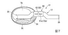
図7は、脛骨Tbに打入された手術器械51を頭側から見た模式図である。手術器械51が生体内に進入し、骨切り刃20の生体への進入深さが所定量になると、ストッパ部60のツマミ部63が脛骨Tbあるいは他の組織等に接触し、それ以上手術器械51を打入することができなくなる。これにより、術者が誤って被叩打部30を強く叩くなどした場合も、ストッパ部60により手術器械51が所定量以上打入されることが防止される。ストッパ部60により規制される骨切り刃20の進入深さの上限値は、止めネジ62を移動することにより長穴12aおよび長穴61aの長さの範囲内で適宜調節することができる。The operation when using the
FIG. 7 is a schematic view of the
図7に示すように、軟組織Stは、脛骨Tbの背側だけでなく、内側(体幹に近い側)にも存在している。内側には、軟組織の中でも、靭帯等のコラーゲンに富むものが多く存在している。コラーゲンに富む軟組織は、弾性も高く、手術器械の本体部で押されると、これを押し返すように反発する。本実施形態の手術器械51は、本体部10の長手方向中間部にクランク部12を有するため、脛骨Tbに打入した際に、クランク部12は、脛骨Tb内に進入している部位よりも前側(腹側)に位置する。その結果、脛骨の内側に位置する軟組織に接触しにくく、軟組織から受ける反力で骨切り刃の刃先の向きが変化する等の事態を好適に抑制することができる。 As shown in FIG. 7, the soft tissue St exists not only on the back side of the tibia Tb but also on the inner side (side closer to the trunk). Inside, there are many soft tissue-rich collagens such as ligaments. Soft tissue rich in collagen has high elasticity, and when pressed by the main body of the surgical instrument, it repels it. Since the
手術器械51が組織内に深く進入すると、術野を見て刃先21の位置を正確に把握することが困難となる。このため、従来の手技では、刃先の位置を腹側から撮影したX線透視像等により確認することが必要に応じて行われる。
従来、HTOでは、金属製のリトラクター等を用いて軟組織を脛骨から引き離しつつ骨切りが行われていることは既に説明した。従来の手技においてX線透視像で刃先の位置を確認する場合は、骨ノミ等の手術器械およびリトラクターのいずれもX線を透過しないため、リトラクターの陰に隠れて刃先の位置が把握できないことがあった。When the
Conventionally, in HTO, it has already been described that osteotomy is performed while pulling the soft tissue away from the tibia using a metal retractor or the like. When checking the position of the cutting edge with X-ray fluoroscopic images in the conventional technique, neither the surgical instrument such as a bone flaw nor the retractor transmits X-rays, so the position of the cutting edge cannot be grasped behind the retractor. There was a thing.
図8は、手術器械51を脛骨に打入した状態のX線透視像のイメージ図である。図8に示すように、X線透視像において窓部71が明りょうに視認できるため、術者は刃先21の位置および脛骨Tbとの位置関係を容易に把握することができる。その結果、より確実に手技を行うことができる。 FIG. 8 is an image view of an X-ray fluoroscopic image in a state where the
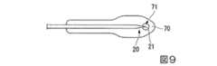
本実施形態の指標部の構成は、上述した窓部71に限られず、様々に変更することができる。例えば、図9に示す変形例のように、刃先21が窓部71の領域内に位置するようにガード70を骨切り刃20に取り付けると、刃先21の位置をより正確に把握することができる。
また、図10に示す変形例のように、ガード70の刃先に対応する位置に、切欠き72を形成して指標部としてもよい。
さらには、ガード70を、X線透過性の高い樹脂等で形成すると、ガードの陰に本体部や骨切り刃が隠れることがなくなるため、指標部を設けなくても刃先の位置を正確に把握することが可能である。ただし、この場合であっても、刃先の位置をよりわかりやすくするために指標部を設けることを禁じるものではない。
ガードを形成するための樹脂材料としては、生体適合性が高くて滅菌可能なものが好ましく、例えば、ポリエーテルエーテルケトン(PEEK)等のフッ素系樹脂や、ポリフェニレンサルファイド(PPS)等を挙げることができる。The configuration of the index part of the present embodiment is not limited to the
Further, as in the modification shown in FIG. 10, a
Furthermore, if the
As the resin material for forming the guard, those having high biocompatibility and sterilizable are preferable, and examples thereof include fluorine resins such as polyether ether ketone (PEEK), polyphenylene sulfide (PPS), and the like. it can.
さらに、図11に示す変形例のように、ガード70の外面のうち、本体部10の厚さ方向の一方に位置する面75aを、骨切り刃20に向かって傾斜する斜面状に形成してもよい。このようにすると、脛骨Tbの近位端付近に切込みを入れる等の場合に、ガードが脛骨の外面に沿いやすく、ガードが脛骨と接触した際に本体部に大きな反力が作用したり、脛骨に大きな力がかかったりすることを抑制することができる。 Further, as in the modification shown in FIG. 11, a
また、ストッパ部の構成も、上述したストッパ部60のものには限定されず、公知の各種機構を適宜採用することが可能である。 The configuration of the stopper portion is not limited to that of the
次に、本発明の第三実施形態について、図12から図14を参照して説明する。本実施形態は、本発明の手術器械の構造を電動のボーンソーに適用した例である。 Next, a third embodiment of the present invention will be described with reference to FIGS. In this embodiment, the structure of the surgical instrument of the present invention is applied to an electric bone saw.
図12は、本実施形態の手術器械101を示す斜視図である。手術器械101は、術者が保持するグリップ102を有する本体103と、本体103に取り付けられた刃部104とを備えている。 FIG. 12 is a perspective view showing the
本体103には、回動軸部105が設けられている。回動軸部105は、本体103に内蔵されるあるいは本体103に接続される電源から供給される電力により、自身の中心軸線を中心に、所定の角度範囲(例えば10度)内で正転と逆転とを交互に繰り返す。
刃部104は、第一実施形態と概ね同様の本体部10および骨切り刃20を有し、基端部が着脱可能に回動軸部105に固定される。刃先22は、鋸歯状に形成されている。
以上の構成により、手術器械101は、電動のボーンソーとして機能する。The
The
With the above configuration, the
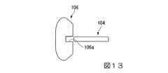
ガード106は、基端部が本体103に固定されており、静止状態の刃部104と略平行に延びるように本体103に取り付けられている。
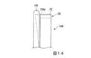
図13は、ガード106および刃部104を基端側から見た図である。ガード106には、刃部104に対向する位置に、刃部104が進入可能な幅の溝106aが形成されている。図14に示すように、溝106aは、ガード106の基端側で最も浅く、かつ先端側に向かって徐々に深くなるように形成されている。これにより、刃部104が回動軸部105を中心として回動し、最もガード106側に移動した場合でも、刃部104とガード106とが干渉しないようになっている。The
FIG. 13 is a view of the
本実施形態の手術器械101においても、上述の各実施形態と同様に、脛骨背側の骨切りを、骨の周囲に存在する軟組織への影響を抑えつつ好適に行うことができる。 Also in the
本実施形態では、ガードと刃部とが刃部の停止時において離間している例を説明したが、これに代えて、図15に示すように、刃部104の停止時において刃部104の一部が溝106a内に位置するように刃部104とガード106とを配置してもよい。
さらに、図示はしないが、第一実施形態等と同様に、ガードが刃部に直接取り付けられた構成としてもよい。このようにすると、刃部を駆動した際にガードも一緒に駆動されるが、刃部の振れ幅が小さい等の場合であれば、このような構成でも実用に耐えうる。In the present embodiment, the example in which the guard and the blade portion are separated when the blade portion is stopped has been described. Instead, as shown in FIG. 15, the
Further, although not shown, the guard may be directly attached to the blade portion as in the first embodiment. If it does in this way, when a blade part is driven, a guard will also be driven together, but if it is a case where the fluctuation width of a blade part is small, such a structure can endure practical use.
以上、本発明の各実施形態について説明したが、本発明の技術範囲は上記実施形態に限定されるものではなく、本発明の趣旨を逸脱しない範囲において各実施形態および変形例における構成要素の組み合わせを変えたり、各構成要素に種々の変更を加えたり、削除したりすることが可能である。 The embodiments of the present invention have been described above. However, the technical scope of the present invention is not limited to the above-described embodiments, and combinations of constituent elements in the embodiments and modifications are within the scope not departing from the gist of the present invention. Can be changed, various changes can be made to each component, and it can be deleted.
例えば、第一実施形態および第二実施形態において、ガードが骨切り刃に直接取り付けられず、骨切り刃と離間して配置されてもよい。このような場合でも、骨切り刃を側面から見た際に、ガードが骨切り刃と重なるようにガードが配置されていれば、軟組織への影響を好適に抑えることが可能である。この場合、ガードの端部は本体部や被叩打部等に、直接あるいは他の部材を介して接続すればよい。 For example, in the first embodiment and the second embodiment, the guard may not be directly attached to the osteotomy blade, but may be disposed apart from the osteotomy blade. Even in such a case, when the guard is arranged so that the guard overlaps the osteotomy blade when the osteotomy blade is viewed from the side, the influence on the soft tissue can be suitably suppressed. In this case, the end portion of the guard may be connected to the main body portion, the hit portion, or the like directly or via another member.
また、ガードは、骨切り刃のうち少なくとも刃先と重なるように配置されていればよいが、骨切り刃全体と重なるように配置された方がより好ましいことは言うまでもない。 Further, the guard may be arranged so as to overlap at least the cutting edge of the bone cutting blade, but it is needless to say that the guard is more preferably arranged so as to overlap the entire bone cutting blade.
さらに、ガードの外面のうち、骨切り刃に対向しない側の面を曲面状に形成し、軟組織に対して過剰な圧力が作用することを抑制してもよい。 Furthermore, the surface on the side that does not face the osteotomy blade of the outer surface of the guard may be formed in a curved surface shape to suppress excessive pressure from acting on the soft tissue.
加えて、本発明の骨切り用手術器械は、HTOのみに使用されるものではない。すなわち、HTO以外の術式であっても、近傍に軟組織が存在する部位の骨切りであれば、好適に使用できることは当然である。 In addition, the surgical instrument for osteotomy of the present invention is not used only for HTO. That is, it is natural that even a surgical technique other than HTO can be suitably used as long as the bone is cut at a site where soft tissue is present in the vicinity.
1、51、101 骨切り用手術器械
10 本体部
12 クランク部
20 骨切り刃
21、22 刃先
40、70、106 ガード
60 ストッパ部
71 窓部(指標部)
72 切欠き(指標部)DESCRIPTION OF
72 Notch (Indicator part)
Claims (7)
Translated fromJapanese前記骨切り刃を側面から見たときに、少なくとも前記骨切り刃の刃先と重なるように配置されたガードと、
を備える、骨切り用手術器械。A bone cutting blade that cuts bone tissue;
A guard disposed so as to overlap at least the cutting edge of the osteotomy blade when the osteotomy blade is viewed from the side;
An osteotomy surgical instrument comprising:
前記本体部は、長手方向中間部に、前記本体部の他の部位に対して変位されたクランク部を有する、
請求項1から4のいずれか一項に記載の骨切り用手術器械。The osteotomy blade is provided at the tip of the plate-shaped main body,
The main body portion has a crank portion that is displaced with respect to other portions of the main body portion in the longitudinal intermediate portion.
The surgical instrument for osteotomy according to any one of claims 1 to 4.
The surgical instrument for osteotomy according to any one of claims 1 to 6, wherein an outer surface of the guard is formed in a curved shape.
Priority Applications (1)
| Application Number | Priority Date | Filing Date | Title |
|---|---|---|---|
| JP2013144777AJP6281759B2 (en) | 2013-07-10 | 2013-07-10 | Osteotomy instrument |
Applications Claiming Priority (1)
| Application Number | Priority Date | Filing Date | Title |
|---|---|---|---|
| JP2013144777AJP6281759B2 (en) | 2013-07-10 | 2013-07-10 | Osteotomy instrument |
Publications (2)
| Publication Number | Publication Date |
|---|---|
| JP2015016095Atrue JP2015016095A (en) | 2015-01-29 |
| JP6281759B2 JP6281759B2 (en) | 2018-02-21 |
Family
ID=52437739
Family Applications (1)
| Application Number | Title | Priority Date | Filing Date |
|---|---|---|---|
| JP2013144777AActiveJP6281759B2 (en) | 2013-07-10 | 2013-07-10 | Osteotomy instrument |
Country Status (1)
| Country | Link |
|---|---|
| JP (1) | JP6281759B2 (en) |
Cited By (5)
| Publication number | Priority date | Publication date | Assignee | Title |
|---|---|---|---|---|
| WO2018020581A1 (en) | 2016-07-26 | 2018-02-01 | オリンパステルモバイオマテリアル株式会社 | Bone-cutting surgical instrument |
| JP2019181144A (en)* | 2018-08-22 | 2019-10-24 | 株式会社ミヤタニ | Osteotomy device |
| JP2020192314A (en)* | 2019-11-19 | 2020-12-03 | 株式会社ミヤタニ | Bone resection instrument |
| WO2020240889A1 (en)* | 2019-05-27 | 2020-12-03 | 株式会社ミヤタニ | Bone resection instrument |
| KR20200139081A (en) | 2018-04-03 | 2020-12-11 | 가부시키가이샤 미야타니 | Fracture instruments |
Citations (7)
| Publication number | Priority date | Publication date | Assignee | Title |
|---|---|---|---|---|
| US2455655A (en)* | 1946-11-01 | 1948-12-07 | Gay V Carroll | Bone saw |
| JPS62213747A (en)* | 1986-03-17 | 1987-09-19 | オリンパス光学工業株式会社 | Ultrasonic incision apparatus for living body tissue |
| US5391169A (en)* | 1991-12-13 | 1995-02-21 | Mcguire; David A. | Patellar tendon harvester |
| JP2007536011A (en)* | 2004-05-07 | 2007-12-13 | アイバランス・メディカル・インコーポレーテッド | Surgical apparatus and surgical method for wedge osteotomy |
| JP2008284342A (en)* | 2007-03-26 | 2008-11-27 | Depuy Products Inc | System, apparatus, and method for cutting bone during orthopedic surgery |
| JP2010110597A (en)* | 2008-11-06 | 2010-05-20 | Shu Nakamura | Crooked osteotome |
| US8287597B1 (en)* | 2009-04-16 | 2012-10-16 | Nuvasive, Inc. | Method and apparatus for performing spine surgery |
- 2013
- 2013-07-10JPJP2013144777Apatent/JP6281759B2/enactiveActive
Patent Citations (7)
| Publication number | Priority date | Publication date | Assignee | Title |
|---|---|---|---|---|
| US2455655A (en)* | 1946-11-01 | 1948-12-07 | Gay V Carroll | Bone saw |
| JPS62213747A (en)* | 1986-03-17 | 1987-09-19 | オリンパス光学工業株式会社 | Ultrasonic incision apparatus for living body tissue |
| US5391169A (en)* | 1991-12-13 | 1995-02-21 | Mcguire; David A. | Patellar tendon harvester |
| JP2007536011A (en)* | 2004-05-07 | 2007-12-13 | アイバランス・メディカル・インコーポレーテッド | Surgical apparatus and surgical method for wedge osteotomy |
| JP2008284342A (en)* | 2007-03-26 | 2008-11-27 | Depuy Products Inc | System, apparatus, and method for cutting bone during orthopedic surgery |
| JP2010110597A (en)* | 2008-11-06 | 2010-05-20 | Shu Nakamura | Crooked osteotome |
| US8287597B1 (en)* | 2009-04-16 | 2012-10-16 | Nuvasive, Inc. | Method and apparatus for performing spine surgery |
Cited By (13)
| Publication number | Priority date | Publication date | Assignee | Title |
|---|---|---|---|---|
| KR102345752B1 (en)* | 2016-07-26 | 2022-01-03 | 올림푸스 테루모 바이오머티리얼 가부시키가이샤 | osteotomy surgical machine |
| KR20190020050A (en) | 2016-07-26 | 2019-02-27 | 올림푸스 테루모 바이오머티리얼 가부시키가이샤 | Osteotomy surgery machine |
| CN109561898A (en)* | 2016-07-26 | 2019-04-02 | 奥林巴斯泰尔茂生物材料株式会社 | Osteotomy surgical instrument |
| JPWO2018020581A1 (en)* | 2016-07-26 | 2019-06-13 | オリンパステルモバイオマテリアル株式会社 | Osteotomy surgical instrument |
| EP3492025A4 (en)* | 2016-07-26 | 2020-01-22 | Olympus Terumo Biomaterials Corp. | BONE CUTTING SURGICAL INSTRUMENT |
| WO2018020581A1 (en) | 2016-07-26 | 2018-02-01 | オリンパステルモバイオマテリアル株式会社 | Bone-cutting surgical instrument |
| US11317925B2 (en) | 2016-07-26 | 2022-05-03 | Olympus Terumo Biomaterials Corp. | Osteotomy surgical apparatus |
| KR20200139081A (en) | 2018-04-03 | 2020-12-11 | 가부시키가이샤 미야타니 | Fracture instruments |
| JP2019181144A (en)* | 2018-08-22 | 2019-10-24 | 株式会社ミヤタニ | Osteotomy device |
| WO2020240889A1 (en)* | 2019-05-27 | 2020-12-03 | 株式会社ミヤタニ | Bone resection instrument |
| GB2597858A (en)* | 2019-05-27 | 2022-02-09 | Miyatani Co Ltd | Bone resection instrument |
| GB2597858B (en)* | 2019-05-27 | 2023-05-03 | Miyatani Co Ltd | Bone Resection Device |
| JP2020192314A (en)* | 2019-11-19 | 2020-12-03 | 株式会社ミヤタニ | Bone resection instrument |
Also Published As
| Publication number | Publication date |
|---|---|
| JP6281759B2 (en) | 2018-02-21 |
Similar Documents
| Publication | Publication Date | Title |
|---|---|---|
| JP6281759B2 (en) | Osteotomy instrument | |
| US12396770B2 (en) | Devices and techniques for treating metatarsus adductus | |
| US11006970B2 (en) | Endoscopic surgical blade and method of use thereof | |
| US9603640B2 (en) | Lower extremity fusion devices and methods | |
| US7846164B2 (en) | Pedicle punch with cannula | |
| CA2851267C (en) | Ultrasonic osteotome | |
| JP2011502550A5 (en) | ||
| WO2016166372A1 (en) | Patient-specific surgical guide | |
| JP6980658B2 (en) | Surgical instrument for osteotomy | |
| JPWO2014168184A1 (en) | Osteosynthesis | |
| TWI638633B (en) | Osteotomy device with an in-vitro alignment component | |
| JPWO2017208318A1 (en) | Bone plate and bone plate system | |
| US20110034932A1 (en) | Surgical chisel assembly and method of use | |
| CN209301235U (en) | Osteotomy limiting device and osteotome device | |
| CN110891495B (en) | SST retractor with radiolucent features | |
| JP2009529350A (en) | Method and apparatus for performing wedge-opening high tibial osteotomy | |
| RU96756U1 (en) | PIN FOR INTRAMEDULAR OSTEOSYNTHESIS OF THE TIBERA | |
| RU2534843C1 (en) | Guide device for long bone resection | |
| JP5433211B2 (en) | Elbow head fracture treatment device and sighting device attached to the elbow head fracture treatment device | |
| CN218922659U (en) | Intubate formula tissue expansion orthopedics minimal access surgery instrument | |
| KR101580858B1 (en) | Skin insision blade for operation | |
| WO2024134716A1 (en) | Guide device | |
| TWM562665U (en) | Osteotomy limit device | |
| Prymka et al. | High Tibial Osteotomy with a Kinematic Navigation System |
Legal Events
| Date | Code | Title | Description |
|---|---|---|---|
| A621 | Written request for application examination | Free format text:JAPANESE INTERMEDIATE CODE: A621 Effective date:20160704 | |
| A131 | Notification of reasons for refusal | Free format text:JAPANESE INTERMEDIATE CODE: A131 Effective date:20170516 | |
| A521 | Request for written amendment filed | Free format text:JAPANESE INTERMEDIATE CODE: A523 Effective date:20170706 | |
| A521 | Request for written amendment filed | Free format text:JAPANESE INTERMEDIATE CODE: A821 Effective date:20170707 | |
| TRDD | Decision of grant or rejection written | ||
| A01 | Written decision to grant a patent or to grant a registration (utility model) | Free format text:JAPANESE INTERMEDIATE CODE: A01 Effective date:20171212 | |
| A61 | First payment of annual fees (during grant procedure) | Free format text:JAPANESE INTERMEDIATE CODE: A61 Effective date:20180111 | |
| R151 | Written notification of patent or utility model registration | Ref document number:6281759 Country of ref document:JP Free format text:JAPANESE INTERMEDIATE CODE: R151 | |
| R250 | Receipt of annual fees | Free format text:JAPANESE INTERMEDIATE CODE: R250 |