JP2015010743A - Cooking equipment - Google Patents
Cooking equipmentDownload PDFInfo
- Publication number
- JP2015010743A JP2015010743AJP2013135121AJP2013135121AJP2015010743AJP 2015010743 AJP2015010743 AJP 2015010743AJP 2013135121 AJP2013135121 AJP 2013135121AJP 2013135121 AJP2013135121 AJP 2013135121AJP 2015010743 AJP2015010743 AJP 2015010743A
- Authority
- JP
- Japan
- Prior art keywords
- hot air
- temperature
- cooking
- exhaust
- humidity
- Prior art date
- Legal status (The legal status is an assumption and is not a legal conclusion. Google has not performed a legal analysis and makes no representation as to the accuracy of the status listed.)
- Pending
Links
Images


Classifications
- F—MECHANICAL ENGINEERING; LIGHTING; HEATING; WEAPONS; BLASTING
- F24—HEATING; RANGES; VENTILATING
- F24C—DOMESTIC STOVES OR RANGES ; DETAILS OF DOMESTIC STOVES OR RANGES, OF GENERAL APPLICATION
- F24C15/00—Details
- F24C15/32—Arrangements of ducts for hot gases, e.g. in or around baking ovens
- F24C15/322—Arrangements of ducts for hot gases, e.g. in or around baking ovens with forced circulation
- F24C15/327—Arrangements of ducts for hot gases, e.g. in or around baking ovens with forced circulation with air moisturising
- A—HUMAN NECESSITIES
- A47—FURNITURE; DOMESTIC ARTICLES OR APPLIANCES; COFFEE MILLS; SPICE MILLS; SUCTION CLEANERS IN GENERAL
- A47J—KITCHEN EQUIPMENT; COFFEE MILLS; SPICE MILLS; APPARATUS FOR MAKING BEVERAGES
- A47J37/00—Baking; Roasting; Grilling; Frying
- A47J37/06—Roasters; Grills; Sandwich grills
- A47J37/0623—Small-size cooking ovens, i.e. defining an at least partially closed cooking cavity
- A47J37/0629—Small-size cooking ovens, i.e. defining an at least partially closed cooking cavity with electric heating elements
- A47J37/0641—Small-size cooking ovens, i.e. defining an at least partially closed cooking cavity with electric heating elements with forced air circulation, e.g. air fryers
Landscapes
- Engineering & Computer Science (AREA)
- Food Science & Technology (AREA)
- Chemical & Material Sciences (AREA)
- Combustion & Propulsion (AREA)
- Mechanical Engineering (AREA)
- General Engineering & Computer Science (AREA)
- Baking, Grill, Roasting (AREA)
- Cookers (AREA)
Abstract
Translated fromJapaneseDescription
Translated fromJapanese本発明は、熱風を吹き付け対象物を加熱する加熱調理装置に関するものである。 The present invention relates to a cooking device that heats an object by blowing hot air.
近年、健康に対する意識が高まってきている。健康維持の方法の一つとして、油脂分の摂取の抑制が推奨されている。そこで、調理油を使用しない或いは調理油を少量利用して加熱調理を行うことができる調理器(特許文献1、特許文献2)が提案されている。 In recent years, awareness of health has increased. As one of the methods for maintaining health, suppression of oil and fat intake is recommended. Then, the cooking appliance (
例えば、特許文献1及び特許文献2には、内部に収容された食品に高温の熱風を吹き付け、食品を加熱調理する調理器が記載されている。これらの調理器では、高温の熱風を吹き付けたり、輻射熱で加熱したりすることで食品を加熱調理するため、少ない調理油で或いは調理油を使用しないで食品の調理を行うことが可能となっている。また、これらの調理器は、熱風を調理器内で循環させて熱風の温度低下を抑制する構成となっている。 For example,
しかしながら、特許文献1及び特許文献2の調理器では、熱風の温度低下を抑制し、温度を調整する構成は示されているが、低めの温度で維持する方法や一度昇温した後、それよりも低い温度に調整することは難しい。そのため、低めの温度を用いたり、温度を下げつつ維持したりする調理メニューの調理を仕上がりよく行うことは困難である。 However, in the cookers of
また、食材は内部に水分を含んでいることが多く、このような食材を加熱するとき、水蒸気が発生する。上述のような従来の調理器では、熱風を循環させる構成となっているため、加熱により食材より発生した水蒸気は熱風と一緒に循環する。食材からの水蒸気が前記熱風に混ざると、循環する熱風の湿度が高くなり、湿度が高い熱風が食材に吹付けられるため、調理後の食材(主に表面)の仕上がりが悪くなる恐れがある。また、調理方法には食材の水分を抜く(乾燥させる)ことが含まれる場合もあり、吹き付ける熱風の湿度が高いと食材から水分が抜けにくく、調理後の食材の仕上がりが悪くなる恐れがある。 In addition, food materials often contain moisture inside, and when such food materials are heated, water vapor is generated. Since the conventional cooker as described above is configured to circulate hot air, water vapor generated from the food by heating circulates together with the hot air. When water vapor from the food material is mixed with the hot air, the humidity of the circulating hot air becomes high, and hot air with high humidity is blown onto the food material, so that the finish of the food material (mainly the surface) after cooking may be deteriorated. In addition, the cooking method may include removing (drying) moisture from the ingredients. If the humidity of the hot air to be blown is high, moisture is not easily removed from the ingredients, and the finish of the ingredients after cooking may be deteriorated.
さらに、食材によっては、加熱により油脂分が蒸発するものもあり、蒸発した油脂分は前記水蒸気と同様、熱風に混ざって調理器の内部を循環する。蒸発した油脂分を含む熱風が食材に吹付けられると、食材に油脂分が再付着してしまい、油脂分の削減の効果が弱くなってしまう恐れがある。 Further, depending on the food, some oils and fats evaporate by heating, and the evaporated oils and fats are mixed with hot air and circulate in the cooker as in the case of the water vapor. When hot air containing evaporated oil and fat is sprayed on the food, the oil and fat is reattached to the food and the effect of reducing the oil and fat may be weakened.
そこで本発明は、熱風を被加熱物に吹き付けて調理を行う加熱調理装置であって、エネルギの消費を抑えつつ任意の温度で調理することができるとともに、水蒸気や蒸発した油脂分等による前記被加熱物の仕上がりの悪化を抑制できる加熱調理装置を提供することを目的とする。 Therefore, the present invention is a cooking device that performs cooking by blowing hot air on an object to be heated, and can cook at an arbitrary temperature while suppressing energy consumption, and is also capable of performing the above-described covering by steam, evaporated oil and fat, and the like. It aims at providing the heat cooking apparatus which can suppress the deterioration of the finish of a heated thing.
上記目的を達成するため本発明は、熱風を被加熱物に吹付け加熱処理を行う加熱調理装置であって、熱風を循環させる循環路と、前記被加熱物を収容する有底箱形状の容器と、前記熱風の少なくとも一部を外部に流出させる流出路と、前記流出路を通過する熱風の流出量を調整する排気調整手段と、前記排気調整手段を制御する制御手段とを備え、前記排気調整手段は、前記流出路の一部に設けられており、前記加熱処理時の状態が所定の条件に収まる前記熱風の流出量となるように、前記制御手段が前記排気調整手段を制御していることを特徴とする。 In order to achieve the above object, the present invention is a cooking device for performing a heat treatment by blowing hot air onto a heated object, a circulation path for circulating the hot air, and a bottomed box-shaped container that accommodates the heated object. An exhaust passage for allowing at least a part of the hot air to flow outside, an exhaust adjustment means for adjusting an outflow amount of the hot air passing through the outflow passage, and a control means for controlling the exhaust adjustment means. The adjusting means is provided in a part of the outflow path, and the control means controls the exhaust adjusting means so that the state during the heat treatment becomes an outflow amount of the hot air that falls within a predetermined condition. It is characterized by being.
この構成によると、前記排気調整手段を制御することで、前記熱風の一部を外部に放出し、前記加熱処理時の状態(温度、湿度、蒸発した油脂分の量)を所定の条件にするので、簡単な制御で、加熱処理時の条件の悪化を抑制することができる。これにより、簡単な制御で、被加熱物の加熱処理後の仕上がりが悪化するのを抑制することができる。 According to this configuration, by controlling the exhaust adjustment unit, a part of the hot air is discharged to the outside, and the state during the heat treatment (temperature, humidity, amount of evaporated oil and fat) is set to a predetermined condition. Therefore, the deterioration of the conditions during the heat treatment can be suppressed with simple control. Thereby, it can suppress that the finish after the heat processing of a to-be-heated object deteriorates by simple control.
本発明にかかる加熱調理装置において、前記循環路には送風手段が備えられており、
前記循環路の前記送風手段の上流側には、前記排気調整手段が前記熱風の流出量を制限しているとき、排気が可能な通気孔を備えていてもよい。In the cooking device according to the present invention, the circulation path is provided with a blowing means,
An upstream side of the circulation unit in the circulation path may be provided with a vent hole capable of exhausting when the exhaust adjustment unit restricts the outflow amount of the hot air.
本発明にかかる加熱調理装置において、前記排気調整手段は、前記流出路を全開又は全閉するものであり、前記制御手段は、前記排気調整手段の全開の時間と全閉の時間の比率を変更し前記全開と全閉とを繰り返すことで流量を調整するようにしてもよい。 In the cooking device according to the present invention, the exhaust adjustment means fully opens or fully closes the outflow passage, and the control means changes a ratio of a full open time and a full close time of the exhaust adjustment means. The flow rate may be adjusted by repeating the full opening and the full closing.
本発明にかかる加熱調理装置において、前記容器の内部温度を検出する温度検出手段を備えており、前記制御手段は、前記温度検出手段から前記内部温度の情報を取得し、前記内部温度が前記所定の条件を満たすよう、前記熱風の流出量を調整するように前記排気調整手段を制御するようにしてもよい。 The cooking device according to the present invention includes temperature detection means for detecting an internal temperature of the container, wherein the control means acquires information on the internal temperature from the temperature detection means, and the internal temperature is the predetermined value. The exhaust adjustment means may be controlled to adjust the outflow amount of the hot air so as to satisfy the above condition.
本発明にかかる加熱調理装置において、前記熱風の湿度を検出する湿度検出手段を備えており、前記制御手段は、前記湿度検出手段から前記熱風の湿度の情報を取得し、前記熱風の湿度が前記所定の条件を満たすよう、前記熱風の流出量を調整するように前記排気調整手段を制御してもよい。 The cooking device according to the present invention includes a humidity detection unit that detects humidity of the hot air, the control unit acquires information on the humidity of the hot air from the humidity detection unit, and the humidity of the hot air is The exhaust adjustment means may be controlled so as to adjust the outflow amount of the hot air so as to satisfy a predetermined condition.
本発明にかかる加熱調理装置において、前記所定の条件が記録された記録手段を備えており、前記制御手段は、前記加熱処理を行うとき、前記記録手段より前記所定の条件を読み出すようにしてもよい。 The cooking device according to the present invention further includes a recording unit in which the predetermined condition is recorded, and the control unit reads out the predetermined condition from the recording unit when performing the heating process. Good.
本発明によると、熱風を被加熱物に吹き付けて調理を行う加熱調理装置であって、エネルギの消費を抑えつつ任意の温度で調理することができるとともに、水蒸気や蒸発した油脂分等による前記被加熱物の仕上がりの悪化を抑制できる加熱調理装置を提供することができる。 According to the present invention, there is provided a cooking device that performs cooking by blowing hot air onto an object to be heated, and can cook at an arbitrary temperature while suppressing energy consumption. It is possible to provide a heat cooking apparatus that can suppress the deterioration of the finished product.
以下に本発明について図面を参照して説明する。
(第1実施形態)
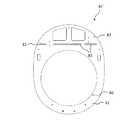
図1は本発明にかかる加熱調理装置の一例の正面図であり、図2は図1に示す加熱調理装置の側断面図である。なお、図1の加熱調理装置では、便宜上、ドアの表示を省略している。The present invention will be described below with reference to the drawings.
(First embodiment)
FIG. 1 is a front view of an example of a cooking device according to the present invention, and FIG. 2 is a side sectional view of the cooking device shown in FIG. In addition, in the heat cooking apparatus of FIG. 1, the display of the door is abbreviate | omitted for convenience.
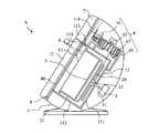
加熱調理装置Aは、熱風を内部に配置された被加熱物に吹付けて加熱処理を行う装置である。図1、図2に示すように、加熱調理装置Aは、筐体1と、内鍋2(容器)と、内鍋2を回転駆動するモータ(駆動部)3と、熱風を発生する加熱部4と、内鍋2に配置され被加熱物を載置する載置部材5と、熱風の流出量を調整する排気ダンパー6(排気調整手段)と、操作部7と、筐体1の前面に配置される前板8とを備えている。内鍋2、モータ3及び加熱部4は筐体1の内部に配置される。また、加熱調理装置Aでは、内鍋2は、その回転軸が鉛直線に対して傾斜した状態で回転する構成となっているが、これに限定されるものではなく、回転軸が鉛直線と平行、すなわち、回転軸が水平面に対して垂直な状態に配置されていてもよい。 The cooking device A is a device that performs heat treatment by spraying hot air on an object to be heated disposed inside. As shown in FIGS. 1 and 2, the cooking device A includes a
筐体1は、加熱調理装置Aの外装を構成する部材であり、前面が開口した形状を有している。そして、前面の開口に前板8が取り付けられている。前板8は、筐体1の開口に取り付け筐体1を補強している。前板8には、後述するとおり円形の貫通孔である開口窓80が形成されている。 The housing |
筐体1の内部には、有底円筒形状の外釜11が設けられている。外釜11は、円板状の底面111と、底面111の辺縁部より立ち上がり円筒形状を有する側周部112とを有している。側周部112の底面111と反対側の端部は、前板8と密着している。図1、図2に示すように、側周部112は開口窓80の縁部に近接した部分に密接している。なお、図2に示すように、加熱調理装置Aでは、開口窓80の内径と側周部112の内径とが同じ内径となっている。しかしながら、これに限定されるものではなく、熱風が漏れないように側周部112の端部を前板8に接合するため、側周部112の内径が開口窓80の内径よりも大きく形成されていてもよい。 A bottomed cylindrical
また、筐体1には、外釜11の開口を開閉可能なように取り付けられたドア12を備えている。図2に示すように、ドア12は、ヒンジを中心に回転する(図2では下方に回転する)扉である。ドア12は筐体1(外釜11)の内部の空気が漏れないように、前板8と密着できる構造(例えば、パッキンを含む構造)となっている。 Further, the
また、外釜11の内部には、内鍋2が回転可能に配置される。内鍋2は、有底円筒形状であり、底部20と、底部20と一体的に連結され、円筒形状を有する周壁部21と、底部20の外側の中心部分、つまり、周壁部21と反対側に突出し、モータ3の後述する出力軸31が固定される接続部22とを備えている。内鍋2は、上述のとおり、外釜11の内部に配置されるものであり、さらに、外釜11の内部に回転可能に配置されている。そのため、内鍋2の底部20は外釜11の底部111よりも小さく、また、内鍋2の周壁部21は外釜11の側周部112よりも小径の円筒形状となっている。内鍋2は外釜11に着脱可能であってもよいし、外釜11だけで被加熱物の加熱調理が可能である場合、内鍋2を省略してもよい。 Moreover, the
さらに、外釜11の側周部112の内鍋2と重なっていない部分には、形成された貫通孔形状(開口)である吹出し口113、排気口114及び吸気口115が備えられている。加熱調理装置Aにおいて、外釜11が前板8に密着されているとともに、ドア12が前板8と密着している。そのため、加熱調理装置Aにおいて、ドア12が閉じている場合、外釜11とドア12とで囲まれる空間では、吹出し口113、排気口114及び吸気口115のみが熱風が通過できる開口となる。 Furthermore, the part which does not overlap with the
そして、外釜11の外側には加熱部4が配置されている。加熱部4は、熱風を循環させるための循環流路40を備えており、循環流路40の内部にはヒータ41と、空気の流れ(熱風)を発生させるファン42とを備えている。加熱部4では、ファン42で発生した気流をヒータ41で加熱し、熱風を発生させている。さらに、外釜11と内鍋2との間に加熱器43を備えているが、内鍋2内を流れる熱風の温度が低下しにくい構成の場合、加熱器43は省略してもよい。 A
循環流路40は、ファン42の吐出側の端部が吹出し口113となっており、ファン42の吸気側の端部が吸気口115となっている。このように形成されていることで、ファン42を駆動すると、循環流路40を流れる熱風が吹出し口113から吹き出され、吸気口115から循環流路40に熱風が流入するようになっている。また、循環流路40には、外釜11とドア12とで囲まれた空間の内圧が高いときは、流通する熱風を外部に逃がし、内圧が低いときは、外部から空気を吸入するための通気孔(不図示)が設けられていてもよい。通気孔は、外釜11とドア12とで囲まれた空間の内部の圧力を調整できる程度の大きさであればよい。 In the circulation flow path 40, the end on the discharge side of the
加熱調理装置Aでは、ファン42で送風され、ヒータ41で加熱された熱風が循環流路40を通過し吹出し口113から内鍋2の内部に流入する。内鍋2の内部に配置された被加熱物(食品)は熱風が吹き付けられることで、加熱される。そして、内鍋2の熱風は吸気口115から循環流路40を通過し、ファン42に戻る。すなわち、加熱調理装置Aでは、内鍋2と循環流路40の間で熱風が循環するようになっている。 In the heating cooking apparatus A, the hot air blown by the
次に、排気口114について説明する。排気口114は、外釜11に流入した熱風の一部を外部に排気するための開口である。排気口114には、加熱調理装置A(筐体1)の外部に通じる排気ダクト116が連通されている。排気口114と排気ダクト116とが流出路を構成している。また、排気口114には、排気口114を開閉する、すなわち、排気口114を流れる熱風の流量(流出量)を調整する排気ダンパー6が備えられている。排気ダンパー6は後述の制御部91からの指示に従って、開又は閉になるように制御される。 Next, the
排気ダンパー6としては、例えば、ヒンジによって回転可能に取り付けられた板状の開閉板を回転させることで、排気口114を開閉するものを挙げることができる。しかしながら、この構成に限定されるものではなく、制御部91からの指示に基づいて排気口114の開閉を行うことができるものを広く採用することができる。 An example of the
なお、加熱調理装置Aにおいて、排気ダンパー6は、電力が供給されていないとき閉じた状態となっている構成となっており、制御部91からの指示に従って開く、いわゆる、常時閉の構成であるものとする。 In the cooking device A, the
排気ダンパー6を閉状態にした場合、排気口114が閉じる。これにより、外釜11は吹出し口113と吸気口115の2つが、外部と連通する開口となる。このとき、吹出し口113は外部から熱風を外釜11に流入させる開口であるため、外釜11の熱風は吸気口115から循環流路40に流入する。このように、排気ダンパー6(排気口114)が閉じられている場合、吹出し口113から内鍋2に吹き付けられる熱風は外釜11と循環流路40の間を循環する。 When the
また、排気ダンパー6を開状態にした場合、排気口114が開く。これにより、外釜11では、排気口114及び吸気口115が、内部の熱風を外部に流出させるための開口となる。そのため、外釜11の熱風の一部は、排気口114及び排気ダクト116を通って加熱料理装置Aの外部に排気さされ、残りは、上述のとおり吸気口115を介して循環流路40に流入(循環)する。このように、排気ダンパー6を動作させることで、加熱調理装置Aの内部で熱風を循環させるか、一部を外部に排気するかを選択することが可能である。 Further, when the
排気ダンパー6を開いたとき、排気ダクト116を介して外部の空気を取り入れることができる構成となっている場合、循環流路40の通気孔を省略してもよい。また、排気ダクト116及び(又は)通気孔を介して、加熱調理装置Aの内部に外部の空気が流入する構成となっている場合、埃、塵等の異物の流入を抑制するフィルタが取り付けられていることが好ましい。 When the
図1、図2に示すように、吹出し口113は、外釜11の側周部112に形成されているため、吹出し口113から吹き付けるだけでは、内鍋2の内部の食品に均一に吹き付けるのは難しい。そのため、筐体1の内部には、外釜11の内部側に、吹出し口113から吹き出された熱風の方向を、内鍋2の内部側に向けて変更する整流部材(風向調整部)13が備えられている。なお、整流部材13はドア12に取り付けられている。 As shown in FIG. 1 and FIG. 2, since the
加熱調理装置Aでは、外釜11の底部111の外側に、モータ3が配置されている。外釜11の底部111の中央部分には、モータ3の出力軸31が貫通する貫通孔を備えている。なお、図示を省略しているが、貫通孔には、出力軸31を回転可能に支持する軸受(ベアリング)が配置されていてもよい。出力軸31の先端には、内鍋2の底部20に設けられた接続部22が接続している。 In the cooking device A, the
また、モータ3は筐体1に固定されており、モータ3が回転することで、出力軸31に接続されている内鍋2が回転する。内鍋2が回転することで、吹出し口113から吹き出された熱風が内部に載置された被加熱物に均一又は略均一に吹き付けることができ、調理むら(加熱むら)を抑制することができる。なお、出力軸31の先端と接続部22とは、出力軸31の軸方向に摺動可能であるとともに、周方向にはずれないような係合方法(例えば、多角形断面を有するものや凹溝と凸条とを嵌合するもの等)が用いられている。また、内鍋2は回転しないような構成であってもよく、その場合、モータ3を含む駆動部は省略することが可能である。 Moreover, the
加熱調理装置Aで被加熱物(食品)を加熱する場合、被加熱物の上下両面から熱風を吹き付けることが好ましい。そこで、加熱調理装置Aにおいて内鍋2の内部には、被加熱物である食品Fdを載置するための載置部材5が取り付けられている。図3は図1に示す加熱調理装置に含まれる内鍋の断面図である。載置部材5は、内鍋2の内部に着脱可能に配置される部材であり、食品Fdを載置する平板状のトレイ51と、トレイ51の食品Fdを載置する載置面と反対側の裏面から突出した脚部52とを備えている。載置部材5では、脚部52が内鍋2の底部20と接触することで、トレイ51が底部20と並んで(例えば、平行となるように)配置される。 When heating an object to be heated (food) with the cooking device A, it is preferable to blow hot air from both the upper and lower surfaces of the object to be heated. Therefore, in the cooking device A, a
トレイ51は、内鍋2の内部に配置される部材であり、平面視円形状を有している。そして、トレイ51は外周部分を折り曲げ、強度を高めている。そして、トレイ51には、熱風が通過する多数の貫通孔(通風部)511を備えている。トレイ51の貫通孔511は、トレイ51に均一又は略均一に分散して配置されている。なお、トレイ51は内鍋2に対して回転しないような、すなわち、相対的な回転を抑制するような部材を介して配置されるようになっている。 The
加熱調理装置Aにおいて、整流部材13で整流された熱風は内鍋2の開口から内部のトレイ51の載置面に吹き付けられている。そして、トレイ51には、貫通孔511が形成されており、載置面に吹き付けられた熱風は、貫通孔511を通過できるようになっている。そして、トレイ51の貫通孔511を通過し、載置された食品Fdにトレイ51側から熱風を吹き付けることができる。このように、載置部材5のトレイ51に載置された食品Fdは、両面より熱風が吹き付けられるので、食品Fdを均一又は略均一に加熱することが可能である。 In the cooking device A, the hot air rectified by the rectifying
トレイ51の裏面には、4個の脚部52が配置されている。貫通孔511を通過した熱風は、トレイ51の裏面と内鍋2の底部20との間の空間内を流動する。そのため、脚部52は柱形状で、熱風の流れが妨げられないような大きさ、形状で形成されている。なお、載置部材5では、脚部52は円柱形状である。そして、脚部52は内鍋2の底部20に接触していることから、載置部材5を内鍋2の内部に配置したとき、脚部52の長さが底部20とトレイ51との間の幅になる。 Four
加熱調理装置Aで食品Fdの加熱調理を行う場合、内鍋2の内部に載置部材5を配置した状態で、トレイ51の上面に食品Fdを載置する。そして、加熱部4で熱風を発生させ、吹出し口113から内鍋2に熱風を流入させている。そして、トレイ51に向けて吹き付けられた熱風が、上面に載置された食品Fdの上面に吹き付けられ、食品Fdが加熱される。 When cooking the food Fd with the heating cooking apparatus A, the food Fd is placed on the upper surface of the
また、トレイ51の上面には、食品Fdが載置されていない部分があり貫通孔511が食品Fdで塞がれない。そのため、食品Fdが載置されていない部分に吹き付けられた熱風の一部は、貫通孔511を通過し、トレイ51の裏面と内鍋2の底部20との間の空間に流入する。そして、上述の通り、貫通孔511は一面に均一な間隔で形成されているため、トレイ51の裏面と内鍋2の底部20との間に流入した熱風は、貫通孔511を通り、食品Fdのトレイ51と対向(接触)している面側から吹き付ける。 In addition, there is a portion where the food Fd is not placed on the upper surface of the
以上のように、載置部材5に食品Fdを載置した後、内鍋2の開口から熱風を流入させる加熱調理装置Aにおいて、食品Fdをかき混ぜたりひっくり返したりすることなく、食品Fdに均一又は略均一に熱風を吹き付けることができる。これにより、食品Fdが混ざったり崩れたりすることなく、均一又は略均一に加熱することが可能である。 As described above, after the food Fd is placed on the
なお、加熱調理装置Aにおいて、トレイ51の中央部分に帯状に形成された非載置領域を備えていてもよい。また、これに限定されるものではなく、中央部分に円形状に非載置領域が形成されていてもよいし、外周部分に円環状に非載置領域が形成されていてもよい。非載置領域の形状及び大きさは、特に限定されるものではない。すなわち、内鍋2を回転しつつ熱風を内鍋2に流入させたとき、上面に載置した食品Fdの上下から均一又は略均一に熱風を吹き付けることができるような形状及び大きさを広く採用することができる。 In addition, in the heating cooking apparatus A, you may provide the non-mounting area | region formed in the strip | belt shape in the center part of the
また、上述した加熱調理装置Aにおいては、内鍋2に載置部材5を配置したものとしているが、これに限定されるものではない。例えば、ポテト、豆等の固く崩れにくい食品を加熱する場合、載置部材5を取り付けなくてもよい。すなわち、固く崩れにくい食品を加熱する場合、内鍋2に直接食品を収納し、内鍋を回転させ、食品自体を動かしてもよい。このように、食品自体が移動することで、熱風の吹付により食品をむらなく加熱することができる。 Moreover, in the heating cooking apparatus A mentioned above, although the mounting
また、内鍋2の内部に内鍋2に対して回転する撹拌部材を設け、食品を撹拌するようにしてもよい。このとき、内鍋2は停止し、撹拌部材が回転するようにしてもよいし、内鍋2が回転し撹拌部材が停止していてもよい。また、内鍋2と撹拌部材の両方が回転するようになっていてもよい。この場合、内鍋2と撹拌部材とは、逆方向に回転するようになっていてもよく、回転速度が異なるように構成されていてもよい。このように、撹拌部材を用いることで食品が撹拌されるので、熱風を吹き付けることで食品をむらなく加熱することができる。 Moreover, the stirring member which rotates with respect to the
加熱調理装置Aの上部には操作部7が配置される。上述しているとおり、操作部7は前板8に取り付け固定されている。操作部7は、現在の加熱調理装置Aの状態、時間、操作メニュー等の各種情報を表示する表示部71と、操作者が入力を行うための入力部72とを備えている。 An
前板8は筐体1の前面の開口と重なる楕円形状を有している。前板8は金属製(例えば、ステンレス、アルミニウム等)の板材であり、筐体1の前面に取り付けることで、筐体1の開口部分の強度を高める補強部材である。なお、筐体1と前板8とが加熱調理装置Aのシャーシとして構成されているともいえる。前板8は、内鍋2にアクセスするために開口窓80が備えられている。 The
外釜11の側周部112と前板8とを密着させることで、外釜11の側周部112と前板8との間に隙間ができるのを抑制し、熱風が漏れるのを抑制している。なお、開口窓80の縁部と外釜11の側周部112とが連続するように形成している場合、加熱調理装置Aを前面に傾けるだけで、外釜11の内部に落ちた食材や水分等を取り除くことができる。そのため、開口窓80の内径と側周部112の内径とが一致するように形成されていることが好ましい。また、前板8を塑性加工可能な板材で形成する場合、前板8と外釜11とを、一体加工(例えば、深絞り加工)で形成することも可能である。 By bringing the side
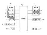
このような、加熱調理装置Aは図4に示すような構成を備えている。図4は本発明にかかる加熱調理装置のブロック図である。図4に示すように、上述もしている、モータ3、加熱部4、排気ダンパー6、操作部7に加え、制御部91(制御手段)、メモリ92(記録手段)、温度検出部93(温度検出手段)、及び計時部94を備えている。制御部91は、各種処理を行う処理装置であり、MPU等の演算処理部を備えている。 Such a cooking device A has a configuration as shown in FIG. FIG. 4 is a block diagram of the cooking device according to the present invention. As shown in FIG. 4, in addition to the
温度検出部93は、内鍋2の内部温度を検出する温度センサを含む構成となっている。温度検出部93は内鍋2の内部温度を検出し、その情報を制御部91に送信する。温度検出部93に用いられる温度センサとしては、内部温度を直接検出する接触型の温度計や非接触で内部温度を検出する放射温度計を挙げることができる。また、必要に応じ、加熱調理装置Aの外部の温度を検出するような構成であってもよい。 The
計時部94は、現在時刻を保持しているとともに、調理開始からの経過時間、ある条件を達成した時点からの経過時間等、制御部91から要求される時間を計測し、その時間情報を制御部91に送信する。なお、以下の説明において、制御部91が時間を管理する場合があり、その場合、特に記載していなくても、計時部94から制御部91に時間の情報が受け渡されているものとする。 The timing unit 94 holds the current time, measures the time required from the
操作部7の表示部71は上述のとおり、加熱調理装置Aの現在の状態(例えば、温度、湿度等)、時間の表示(例えば、調理開始からの時間、現在の時刻等)、操作(例えば、現在行っている操作等)を表示するための表示装置である。表示部71は制御部91の制御によって表示を行うものとなっている。なお、表示部71は例えば、液晶パネルのような映像、文字等を表示可能な表示装置を備えた構成であってもよいし、LED等の発光体で状態を示す構成であってもよい。 As described above, the
また、入力部72は、調理を行う者(以下、調理者とする)が所望の操作を入力するための入力インターフェースである。入力部72で入力された操作の情報は制御部91に送られる。なお、図1に示すように、入力部72は、3個の押しボタンを備えた構成としているが、これに限定されるものではなく、0〜9までの数字を備えた、いわゆるテンキーや十字キー等を備える構成であってもよい。また、表示部71に画像として入力部72を表示し、調理者の指又は専用の接触部材(例えば、タッチペン)が接触することで、入力を検出する、いわゆるタッチパネルであってもよい。 The
そして、制御部91は、モータ3、加熱部4及び排気ダンパー6の動作を制御している。また、加熱調理装置Aは制御部91がアクセス可能なメモリ92を備えており、メモリ92には、調理メニューごとに調理条件(温度、時間、内鍋の回転の有無等)が格納されたデータベース(不図示)が収納されている。なお、メモリ92は、読み出し専用のROMや書き換え可能なRAM等を含む構成であってもよいし、メモリカード等の抜き差し可能なメモリであってもよい。情報を記録することができる装置を広くメモリと称している。 The
加熱調理装置Aで調理を行う場合において、被加熱物によって或いは調理メニューによって調理に要する温度又は時間が決まっている場合がほとんどである。そのため、加熱調理装置Aでは、熱風の温度及び内鍋2の内部温度の管理が重要となる。本発明では、温度検出部93で内鍋2の内部温度を検出し、制御部91は温度検出部91から内部温度の情報を取得している。内部温度に基づいて加熱部4、排気ダンパー6を制御している。なお、実際には、モータ3も制御し内鍋2の回転制御を行っているが、この内鍋2の回転は、内鍋2の内部に配置された被加熱物に均一又は略均一に熱風が吹き付けられるようにするためのものであり、内鍋2の温度上昇とは直接関係ない。そのため、以下の説明において、制御部91によるモータ3の制御は省略する。 When cooking with the cooking device A, the temperature or time required for cooking is mostly determined by the object to be heated or by the cooking menu. Therefore, in the heating cooking apparatus A, management of the temperature of hot air and the internal temperature of the
加熱調理装置Aにおける内鍋2の温度調整について以下に説明する。なお、本実施形態において、ヒータ41及びファン42は一定の出力で運転されるものとしている。図5に示すように排気ダンパー6は全開又は全閉となるような動作をする。 The temperature adjustment of the
まず、排気ダンパー6と内部温度tの関係について説明する。排気ダンパー6を閉状態にすると、外釜11とドア12とで囲まれた空間から外部に空気がほとんど漏れない。外釜11とドア12とで囲まれた空間の熱風は、吸気口115から循環流路40に流入する。すなわち、熱風は外釜11とドア12で囲まれた空間と加熱部4の間(加熱調理装置Aの内部)を循環する。そして、循環流路40を通過する熱風はヒータ42で加熱されるため、循環する熱風の温度は上昇し、外釜11とドア12とで囲まれた空間(内鍋2)の内部温度tは上昇する。なお、加熱調理装置Aでは、外釜11とドア12とで囲まれた空間に内鍋2を配置しているため、内鍋2と称していても、外釜11とドア12とで囲まれた空間を示す場合がある。 First, the relationship between the
また、排気ダンパー6を開にすると、外釜11とドア12で囲まれた空間と加熱部4との間を循環している熱風の一部が排気口114及び排気ダクト116を介して加熱調理装置Aの外部に流出する。流出した熱風と入れ替わるように、排気ダクト116及び(又は)通気孔を介し、加熱調理装置Aの外部の空気が流入する。このとき、加熱調理装置Aの外部に流出する熱風に対し外部から流入する空気は温度が低いため、加熱調理装置Aの内部の熱風の温度が低下する。このことから、排気ダンパー6を開状態にすることで、熱風の温度が低下し、内鍋2の内部温度tを下降させる又は一定に保つことができる。 When the
なお、熱風の温度の低下は、加熱調理装置Aの外部の空気の温度とその空気の流入量によって決定する。加熱調理装置Aでは、排気ダンパー6の開と閉との比率を調整することで、熱風の流出量、すなわち、外気の流入量を調整し、熱風の温度及び内鍋2の内部温度tを調整している。そして、制御部91は、温度検出部93から取得している内部温度tが設定温度となるように、排気ダンパー6の開の比率(単位時間当たりの開時間)を制御する。 In addition, the fall of the temperature of a hot air is determined by the temperature of the air outside the cooking apparatus A, and the inflow amount of the air. In the cooking device A, the ratio of the opening and closing of the
次に加熱調理装置Aの調理メニューについて説明する。加熱調理装置Aのメモリ92には上述のとおり、調理メニューのデータベースが備えられており、データベースには調理時の温度、その温度を維持する時間等の調理条件が含まれている。調理条件には、調理時の温度、その温度を維持する時間等の条件が含まれている。調理メニューの一例である第1調理メニューC1(例えば、とんかつ、とする)の調理条件は、「運転開始からなるだけ早く内鍋2の内部温度tを第1温度T1に上昇させる」、「内鍋2の内部温度tを第1温度T1で一定時間維持する」、「なるだけ早く内鍋2の温度を低下させる」であるものとする。 Next, the cooking menu of the heating cooking apparatus A will be described. As described above, the cooking menu A has a cooking menu database in the
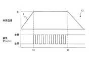
第1調理メニューC1の調理を行うときの加熱調理装置Aの動作について説明する。図5は本発明にかかる加熱調理装置の調理動作の一例の内鍋内部の温度と排気ダンパーの動作状態とを示すタイミングチャートである。図5に示すタイミングチャートでは、上部が内鍋2の内部温度tを示しており、下部が排気ダンパー6の動作を示している。 Operation | movement of the heat cooking apparatus A when cooking the 1st cooking menu C1 is demonstrated. FIG. 5 is a timing chart showing the temperature in the inner pot and the operating state of the exhaust damper as an example of the cooking operation of the cooking device according to the present invention. In the timing chart shown in FIG. 5, the upper part shows the internal temperature t of the
まず、調理者は入力部71で所望する動作(ここでは、第1調理メニューC1の選択)を行う。入力部71へ入力があると、入力部71は、その入力(ここでは、第1調理メニューC1の決定)の情報を制御部91に送る。制御部91は、メモリ92のデータベースから第1調理メニューC1の調理条件を呼出す。 First, the cook performs a desired operation (here, selection of the first cooking menu C1) at the
そして、入力部71に調理開始の入力があると、調理開始の情報が制御部91に送られ、制御部91はヒータ41とファン42とを駆動させ、吹出し口113から熱風の吹き出しを開始する。調理開始とともに、温度検出部93は、内鍋2の内部温度tの検出を行っており、その情報を逐一(定期的に)制御部91に受け渡している。そして、制御部91は、内部温度tの情報に基づいて、排気ダンパー6の開の比率を調整し、その開の比率で排気ダンパー6を制御する。 When there is an input to start cooking at the
図5に示すように、加熱調理装置Aにおいて、調理開始直後は、内鍋2の内部温度tが第1温度T1よりも低い。そして、第1調理メニューC1の調理条件は、「なるだけ早く内鍋2の内部温度tを第1温度T1に到達させる」であるため、制御部91では、内鍋2の内部温度tが第1温度T1に到達するまで排気ダンパー6を閉状態に制御する。これにより、熱風は加熱調理装置Aの内部を循環し、循環するときにヒータ41によって加熱されるため、急激に温度が上昇する。図5では、開始後時間S1で第1温度T1に到達している。 As shown in FIG. 5, in the heating cooking apparatus A, immediately after the start of cooking, the internal temperature t of the
第1調理メニューC1の調理条件では、「内鍋2の内部温度tを第1温度T1で一定期間(ここでは、調理開始から時間S2まで)維持する」である。熱風を加熱調理装置Aの内部で循環させ続けると熱風の温度がさらに上昇するため内鍋2の内部温度tも第1温度T1を超えて上昇してしまう。そこで、制御部91は、排気ダンパー6を開状態に制御し、排気口114から熱風の一部を排出することで、熱風の温度上昇を抑える。 The cooking condition of the first cooking menu C1 is “maintain the internal temperature t of the
なお、排気ダンパー6を開閉することで、加熱調理装置Aの内部を流れる熱風の温度は昇降する。熱風は内鍋2の内部に吹付けられるが、内鍋2の温度は、熱風の温度の昇降による影響は少なく、ほぼ一定に保たれる。そのため、図6に示すように、内鍋2の内部温度tは第1温度T1に維持されているものとしている。 In addition, the temperature of the hot air which flows through the inside of the heating cooking apparatus A raises / lowers by opening and closing the
制御部91の制御を詳しく説明する。制御部91は、内鍋2の内部温度tの情報を温度検出部93から取得している。制御部91は開の比率を予め決められた値とし、排気ダンパー6の開閉制御を行う。そして、温度検出部93からの内部温度tの情報に基づいて、排気ダンパー6の開の比率を調整(微調整)するようにしている。なお、図5では、制御部91は排気ダンパー6の開の比率が0.5(すなわち、開と閉とが同じ時間)となるように、排気ダンパー6の開閉を制御している。 The control of the
また、外気温、内部温度tの設定温度(ここでは、第1温度T1)及び排気ダンパー6の開の比率の情報をデータベースとしてメモリ92に格納しておき、そのデータベースから条件に合致した開の比率で排気ダンパー6を制御するようにしてもよい。このとき、制御部91は、開の比率を微調整するようにしてもよい。このとき、温度検出部93は、加熱調理装置Aの外部の温度を検出することができる構成となっていてもよいし、別途外部の温度を検出しその情報を制御部91に送信する検出部を備えていてもよい。ここでは、温度検出部93が検出しているものとしている。 Also, information on the outside air temperature, the set temperature of the internal temperature t (here, the first temperature T1) and the opening ratio of the
その後、第1調理メニューC1の調理条件が、「内鍋2の内部温度tをなるだけ早く低下させる」であるため、加熱調理装置Aの内部の高温の熱風が速やかに外部に排出されるように制御部91は排気ダンパー6を制御する。制御部91は、熱風を外部に効果的に排出するため、排気ダンパー6が開状態を維持するように制御する(図5参照)。このとき、熱風を被加熱物に吹き付ける必要がないので、ヒータ41は停止させる。一方、排気口114からの排気を促進させるため、ファン42は回転させた状態を維持する。 Thereafter, since the cooking condition of the first cooking menu C1 is “reducing the internal temperature t of the
以上のように調整することで、排気ダンパー6を開閉するといった、簡単な方法で熱風の温度調整を行うことが可能である。また、熱風の排気、すなわち、外部からの空気の流入によって熱風の温度調整を行うため、ヒータ42の出力を調整するものに比べて、短時間で熱風の温度を調整することができる。この特性のため、本発明にかかる加熱調理装置Aでは、熱風の温度を精度よく調整することができ、内鍋2の内部温度tを正確に調整することが可能である。このことから、調理後の被加熱物を良好な仕上がりとすることが可能である。 By adjusting as described above, it is possible to adjust the temperature of the hot air by a simple method such as opening and closing the
また、調理者によって異なる調理メニューが選択される場合もある。例えば、第2調理メニューC2(例えば、ハンバーグとする)の調理条件として、内鍋2の内部温度tを第1温度T1で一定時間維持」した後、「内部温度tを第1温度T1よりも低い第2温度T2で一定時間維持」した後、冷却するとする。このような第2調理メニューで調理するときの加熱調理装置Aの動作について図面を参照して説明する。図6は異なる調理メニューで調理を行うときの加熱調理装置の内部温度と排気ダンパーの動作とを示すタイミングチャートである。 In addition, different cooking menus may be selected depending on the cook. For example, as the cooking condition of the second cooking menu C2 (for example, hamburger), the internal temperature t of the
第2調理メニューC2の調理条件は、制御部91による排気ダンパー6の制御は、時間S2までは、図5に示す第1調理メニューC1と同じであるため、その部分の詳細は省略する。内鍋2の内部温度tを第1温度T1から第2温度T2に変更するためには、多くの熱風を外部に排気すればよい。そのため、制御部91は時間S2経過後内鍋2の内部温度tが第2温度T2になる(時間S21)まで、排気ダンパー6を全開にする。内鍋2の内部温度tを第2温度T2で維持するためには、熱風の温度を低くする必要がある。 The cooking conditions of the second cooking menu C2 are the same as those of the first cooking menu C1 shown in FIG. 5 until the control of the
そのため、制御部91は、排気ダンパー6の開の比率を大きくして制御を行っている。図6に示す例において、制御部91は排気ダンパー6の開の比率が0.75(すなわち、開が閉の3倍の時間)となるように、排気ダンパー6の開閉を制御している。なお、この開の比率も、上述の第1調理メニューC1の調理時と同様、所定の開の比率で排気ダンパー6を制御しておき、内鍋2の内部温度tが第2温度T2となるように、調整するようにしているが、これに限定されない。 Therefore, the
そして、制御部91は、内鍋2の内部温度tが第2温度T2になった状態から、一定時間経過するまで(調理開始後時間S21から時間S3まで)、排気ダンパー6の開の比率を維持し、排気ダンパー6を制御する。その後、制御部91は、排気ダンパー6を開状態で維持するように制御するとともに、ヒータ41を停止する。 And the
以上のように、排気ダンパー6の開閉を制御することで、内鍋2の内部温度tを適宜調整することが可能である。なお、加熱調理装置Aでは、内鍋2の内部温度tの温度を変更する場合、温度上昇を伴うときは排気ダンパー6を閉状態で維持し、温度降下を伴うときは排気ダンパー6を開状態で維持するようにしているがこれに限定されない。例えば、内鍋2の内部温度tを第1温度T1から第2温度T2に低下させるとき、第2温度T2に維持するときの開の比率で排気ダンパー6の開閉制御を行うことで低下させてもよい。この場合、図6に示すように、内鍋2の内部温度tの降下が緩やかとなる。このように制御して温度変化を緩やかにすることは、急激な温度低下が悪影響を及ぼすような調理メニューの場合、有効である。 As described above, the internal temperature t of the
以上示したように、熱風を吹き付けることで被加熱物の加熱調理を行う加熱調理装置に排気口を設け、排気口を開閉するための排気ダンパーを設けることで、内部を流れる熱風の温度を容易に制御でき、被加熱物の加熱温度及び調理時間を正確に調整できる。これにより、被加熱物を過不足なく加熱することが可能である。 As shown above, the temperature of hot air flowing inside can be easily increased by providing an exhaust port in a cooking device that cooks the object to be heated by blowing hot air and providing an exhaust damper for opening and closing the exhaust port. And the heating temperature and cooking time of the object to be heated can be accurately adjusted. Thereby, it is possible to heat a to-be-heated material without excess and deficiency.
なお、上述の加熱調理装置Aにおいて、制御部91は、内鍋2の内部温度tに基づいて排気ダンパー6の開閉制御を行っているが、それに限定されない。例えば、排気ダンパー6の開の比率とその開の比率を維持する時間を与えるものであってもよい。また、内鍋2の内部温度tと外部の温度との両方に基づいて、排気ダンパー6の開の比率を計算するような構成であってもよい。 In addition, in the above-mentioned cooking-by-heating apparatus A, although the
(第2実施形態)
本発明にかかる加熱調理装置の他の例について図面を参照して説明する。図7は本発明にかかる加熱調理装置の他の例のブロック図である。図7に示す加熱調理装置Bは湿度検出部95(湿度検出手段)を備えており、それ以外の部分は加熱調理装置Aと同じ構成であり、実質上同じ部分には同じ符号を付すとともに、同じ部分の詳細な説明は省略する。(Second Embodiment)
Another example of the cooking device according to the present invention will be described with reference to the drawings. FIG. 7 is a block diagram of another example of the cooking device according to the present invention. The cooking device B shown in FIG. 7 includes a humidity detection unit 95 (humidity detection means), and other parts have the same configuration as the cooking device A, and substantially the same parts are denoted by the same reference numerals. Detailed description of the same part is omitted.
湿度検出部95は、内鍋2の内部の湿度を検出する湿度センサを含む構成となっている。湿度検出部95は熱風の湿度を検出し、その情報を制御部91に送信する。なお、内鍋2の内部の熱風は、循環流路40を流通する熱風とほぼ同じとなるので、循環流路40を通過する熱風の湿度を検出するようにしてもよい。このとき、湿度検出部95は、流速が低くなるファン42の吸気側に配置されることが好ましい。 The
また、加熱調理装置Aで示した、とんかつ、ハンバーグのような調理メニューは、高温の熱風を短時間に被加熱物に吹き付けることで加熱調理を行っている。加熱調理装置Bでは、このような短時間で行う調理メニューの調理が可能であるとともに、乾燥した(一定以下の湿度の)熱風を被加熱物に長時間吹き付ける、例えば、魚の干物、ドライフルーツ等の乾燥食品の加工にも利用可能となっている。 In addition, the cooking menu such as tonkatsu and hamburger shown in the heating cooking apparatus A performs cooking by blowing hot hot air on the object to be heated in a short time. In the cooking device B, cooking on the cooking menu can be performed in such a short time, and dried hot air (with a humidity below a certain level) is blown on the heated object for a long time, for example, fish dried fish, dried fruit, etc. It can also be used to process dried foods.
熱風を吹き付けて被加熱物を加熱すると、被加熱物の内部の水分が蒸発する。加熱調理装置Bにおいて、蒸発した水分が熱風とともに循環し、熱風の湿度(相対湿度)が上昇する。熱風の湿度が上昇すると、被加熱物に湿った熱風を吹き付けることになるため、被加熱物が乾燥しにくく、予め決められた時間では、乾燥食品の仕上がりが悪くなる場合がある。そのため、加熱調理装置Bが乾燥食品の加工を行う場合、熱風の温度の調整に加え、熱風の湿度の調整も重要になる。 When the object to be heated is heated by blowing hot air, moisture inside the object to be heated evaporates. In the cooking device B, the evaporated water circulates with the hot air, and the humidity (relative humidity) of the hot air increases. When the humidity of hot air rises, wet hot air is blown onto the object to be heated, so that the object to be heated is difficult to dry, and the finish of the dried food may be deteriorated in a predetermined time. Therefore, when the heating cooking apparatus B processes dry food, in addition to the adjustment of the temperature of the hot air, the adjustment of the humidity of the hot air is also important.
加熱調理装置Aのように排気ダンパー6の開閉で熱風の温度調整を行う場合、温度の調整がやりやすく、短時間で正確に決められた温度に調整することが可能である。一方、排気ダンパー6の開閉で熱風の温度を調整する場合、加熱した熱風に外部の低温の空気を混ぜて温度を調整するためエネルギ消費が多く、乾燥食品を加工するときのように長時間にわたって熱風を吹き付ける場合、効率が悪くなる。 When the temperature of the hot air is adjusted by opening and closing the
また、加熱調理装置Bにおいて、乾燥食品の加工に用いる熱風の温度は、食品の調理(揚げ、焼き)に用いる熱風の温度に比べて低く、温度の調整の幅も狭くなっており、加工時の温度の条件が、食品の調理に比べて緩やかである。すなわち、乾燥食品の加工を行う場合には、熱風の温度は、ある程度の範囲に入っていればよく、高レベルの正確さが要求されない。 Moreover, in the heating cooking apparatus B, the temperature of the hot air used for the processing of the dried food is lower than the temperature of the hot air used for the cooking (fried or baked) of the food, and the range of temperature adjustment is narrow. The temperature conditions are milder than food cooking. That is, when processing dried food, the temperature of the hot air only needs to be within a certain range, and a high level of accuracy is not required.
そのため、加熱調理装置Bでは、加熱部4のヒータ41の出力(温度)を調整することで熱風の温度調整を行っている。つまり、加熱調理装置Bは排気ダンパー6を開閉して外部の空気を流入させなくても、熱風の温度調整が可能となっている。なお、ヒータ41の出力の調整では、熱風の温度調整に時間がかかる場合があるが、ヒータ41で消費されるエネルギを抑えることが可能である。 Therefore, in the cooking device B, the temperature of the hot air is adjusted by adjusting the output (temperature) of the
また、熱風を吹き付けることで乾燥食品の加工を行う場合、熱風の温度よりも湿度が重要である場合多い。そこで、加熱調理装置Bでは、熱風の湿度上昇を抑制するため、排気ダンパー6を開き、加熱調理装置Bの内部の湿った(湿度が高い)熱風を外部に放出し、外部の乾燥した(熱風よりも湿度が低い)空気を取り込むように構成されている。 In addition, when processing dried food by blowing hot air, humidity is often more important than the temperature of the hot air. Therefore, in the cooking device B, in order to suppress an increase in the humidity of the hot air, the
なお、加熱調理装置Bにおいて、短時間で高温の熱風を吹き付ける調理メニューを調理する場合は、加熱調理装置Aと同様、熱風を加熱しつつ外部の低温の空気を流入させて温度調整を行っている。そのため、以下の説明では、加熱調理装置Bで乾燥食品の加工を行う場合について説明する。 In addition, when cooking a cooking menu that blows hot hot air in a short time in the cooking device B, as in the heating cooking device A, the temperature is adjusted by injecting external low-temperature air while heating the hot air. Yes. Therefore, in the following description, a case where dry food is processed by the cooking device B will be described.
本発明にかかる加熱調理装置Bにおける乾燥食品の加工メニューについて説明する。上述のとおり、加熱調理装置Bのメモリ92のデータベースには、上述のような調理メニューに加え、加工を行うときの温度、湿度及びこれらを維持する時間等の加工条件を含む加工メニューを備えている。 The processing menu of the dried food in the heat cooking apparatus B according to the present invention will be described. As described above, the database in the
加工メニューの一例である第1加工メニューD1(ここではドライフルーツの加工)の加工条件について説明する。第1加工メニューD1の加工条件は、「内鍋2の内部温度tを一定以内の温度上昇率で第3温度T3に上昇させる」、「内鍋2の内部温度tを第3温度T3及び熱風の湿度hを第1湿度H1以下で一定時間維持する」、「内鍋2の内部温度tを低下させる」であるものとする。 Processing conditions of the first processing menu D1 (here, processing of dried fruits), which is an example of a processing menu, will be described. The processing conditions of the first processing menu D1 are “increase the internal temperature t of the
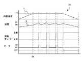
第1加工メニューD1の加工を行うときの加熱調理装置Bの動作について説明する。図8は本発明にかかる加熱調理装置で乾燥食品を加工するときのタイミングチャートである。なお、加工開始までの動作は、加熱調理装置Aで調理を行う場合と同じであるため省略する。加工開始の情報を受けると、制御部91はヒータ41とファン42とを駆動させ、吹出し口113から熱風の吹き出しを開始する。加工開始とともに、温度検出部93は、内鍋2の内部温度tの検出を行っており、その情報を逐一(定期的に)制御部91に受け渡している。 Operation | movement of the heat cooking apparatus B when processing the 1st process menu D1 is demonstrated. FIG. 8 is a timing chart when the dried food is processed by the cooking device according to the present invention. In addition, since operation | movement until a process start is the same as the case where it cooks with the heating cooking apparatus A, it abbreviate | omits. Upon receipt of the processing start information, the
また、湿度検出部95は、熱風の湿度hを検出し、その情報を逐一(定期的に)制御部91に受け渡している。なお、温度検出部93の温度検出と、湿度検出部95の湿度検出とは同時であってもよいし、異なっていてもよい。そして、制御部91は、内部温度tの情報と熱風の湿度hの情報に基づいて、排気ダンパー6の開閉を制御する。 Moreover, the
図8に示すように、加熱調理装置Bにおいて、加工開始直後は、内鍋2の内部温度tが第3温度T3よりも低い。そして、第1加工メニューD1の加工条件は、「内鍋2の内部温度tを一定以内の温度上昇率で第3温度T3に到達させる」である。このことは、「ヒータ41の出力を一定とし、加工開始から時間S4に内部温度tが第3温度T3にする」と同じことである。そのため、制御部91は上述の条件を満たすようなヒータ41の出力O1を決定し、その出力O1となるようにヒータ41を制御する。 As shown in FIG. 8, in the heating cooking apparatus B, immediately after the start of processing, the internal temperature t of the
これにより、熱風は加熱調理装置Bの内部を循環し、循環するときにヒータ41によって加熱されるため温度が上昇し、その熱風が吹き付けられる内鍋2の内部温度tも上昇する。図8では、開始後時間S4で第3温度T3に到達している。なお、制御部91は、内部温度tを上昇させている間は、湿度の調整は行わず、排気ダンパー6は閉状態に制御する。 Thereby, since hot air circulates the inside of the heating cooking apparatus B and is heated by the
第1加工メニューD1の加工条件は、「内鍋2の内部温度tを第3温度T3及び熱風の湿度hを第1湿度H1以下で一定時間維持する」である。そのため、制御部91は、湿度検出部95からの湿度の情報に基づき排気ダンパー6を開閉している。The processing condition of the first processing menu D1 is “maintain the internal temperature t of the
熱風を加熱調理装置Bの内部で循環させる場合、熱風の熱は被加熱物に吸収されたり、外釜11、前板8等の装置の一部を介して外部に放出されたりする。図8に示すように、内部を循環する熱風をヒータ41で加熱しているため、吹出し口113から吹き出される熱風の温度は、一定又は略一定に調整されている。一方、図8に示しているように、被加熱物に熱風を吹き付けることで、熱風の湿度は上昇する。制御部91は、熱風の湿度hが第1湿度H1を超える(第1湿度H1に到達する)と、排気ダンパー6を開く。 When the hot air is circulated inside the cooking device B, the heat of the hot air is absorbed by the object to be heated, or is released to the outside through some of the devices such as the
排気ダンパー6を開くことで、湿度が高い熱風が外部に排出され、外部の空気が流入するため、熱風の湿度hが低下する。外部の空気の相対湿度が高い場合もあるが、加熱調理装置Bの外部の空気を、内部を循環する熱風の温度まで昇温した場合、熱風よりも湿度が低いことがほとんどである。そのため、外部の空気の相対湿度が高い場合でも、内部に流入させ、熱風と混合させることで、熱風の湿度を低減させることが可能である。 By opening the
また、排気ダンパー6を開き、熱風に外部の空気を混合した場合、湿度hとともに温度も下降する。熱風の温度が低下すると、内鍋2の内部温度tも下降し、加工条件を満たさなくなる場合がある。そこで、制御部91は、熱風の温度低下を抑制するため、ヒータ41の出力を上げる(出力O2となる)ように制御する(図8参照)。このヒータ41の出力の変動量は、内鍋2の内部温度tが第3温度T3となるような制御である。また、これ以外にも、流入する空気の温度及び流量に基づいて決めるようにしてもよい。 In addition, when the
そして、制御部91は、熱風の湿度hが第1湿度H1よりも低い基準湿度H0に到達したとき、排気ダンパー6を閉じるように制御している。そして、排気ダンパー6を閉とすると同時に、ヒータ41の出力を元の出力O1に戻す。このように制御することで、ヒータ42を高い出力O2で制御する割合を減らすことができる。これに限定されるものではなく、より低い基準湿度となるまで排気ダンパー6を開状態とするようにしてもよい。 And the
また、熱風の湿度hを第1湿度H1以下に調整するとき、制御部91は排気ダンパー6を一定時間開状態に維持するようにしているが、これに限定されるものではない。例えば、(例えば、第1実施形態のように)排気ダンパー6を一定の動作周期で開閉し湿度を一定又は略一定に保つように制御してもよい。このような制御を行うことで、低温の外部の空気が短時間の間に多量に流入し、熱風の温度が急激に下降するのを抑制することができる。熱風の温度の変化が緩いので、ヒータ41の出力の調整幅を小さくすることができ、消費エネルギを抑えることが可能である。 Further, when the humidity h of the hot air is adjusted to be equal to or lower than the first humidity H1, the
その後、第1加工メニューD1の加工条件が、「内鍋2の内部温度tを低下させる」であるため、加熱調理装置Aの内部の高温の熱風が速やかに外部に排出されるように制御部91は排気ダンパー6を制御する。制御部91は、熱風を外部に効果的に排出するため、排気ダンパー6が開状態を維持するように制御する(図8参照)。このとき、熱風を被加熱物に吹き付ける必要がないので、ヒータ41は停止させる。一方、排気口114からの排気を促進させるため、ファン42は回転させた状態を維持する。 Thereafter, since the processing condition of the first processing menu D1 is “reducing the internal temperature t of the
なお、第1開口メニューD1の加工条件では、温度の低下率についての指示がないため、制御部91は、上述のように、排気ダンパー6とヒータ41とを制御しているがこれに限定されない。例えば、温度低下率が一定以内との限定がある場合、排気ダンパー6を開かずに温度低下を行ったり、一定の周期で開閉行うとともに、ヒータ41を停止又は出力を小さくして温度を低下させる制御であってもよい。 In the processing conditions of the first opening menu D1, there is no instruction about the temperature decrease rate, and thus the
このように、加熱調理装置Bは、排気ダンパー6の開閉を制御して、湿度の調整を行うことで、被加熱物の乾燥度を正確に調整して加工を行うことができる。 Thus, the heating cooking apparatus B can process by controlling the opening / closing of the
以上示したような、加熱調理装置を用いることで、被加熱物に高温の熱風を短時間吹き付けるような調理を行うときの温度調整を正確に行うことができるとともに、被加熱物に低温の熱風(外部の空気よりも高温ではあるが調理に利用するよりも低温の熱風)で加工を行うときの温度調整及び湿度調整を正確に行うことが可能である。 By using the heating cooking apparatus as described above, it is possible to accurately perform temperature adjustment when cooking such that high-temperature hot air is blown on the object to be heated for a short time, and low-temperature hot air is applied to the object to be heated. It is possible to accurately perform temperature adjustment and humidity adjustment when processing is performed with (hot air that is hotter than external air but lower in temperature than that used for cooking).
なお、本実施形態では、被加熱物に熱風を吹き付けることで、水分が蒸発して熱風の湿度が上昇すると説明しているが、これに限定されない。例えば、油脂分を加熱することで、油脂分が蒸発しそれが熱風に含まれる場合もある。このような場合も、排気ダンパー6を開き、熱風の一部を排気することで、熱風に含まれる蒸発した油脂分を減らすことができ、被加熱物に蒸発した油脂分が再付着するのを抑制することができ、仕上がりの悪化を抑制することができる。また、油脂分の摂取量を減らすことも可能である。 In the present embodiment, it is described that the hot air is blown on the object to be heated, whereby the moisture is evaporated and the humidity of the hot air is increased. However, the present invention is not limited to this. For example, by heating the oil and fat, the oil and fat may be evaporated and included in the hot air. Also in such a case, by opening the
なお、本実施形態では、排気ダンパー6の開閉に合わせて、ヒータ41の出力を調整し、内鍋2の内部温度tの変化を抑制しているが、これに限定されるものではない。例えば、ヒータ41の出力は一定のままで、内鍋2を外から加熱している加熱器43の出力を調整するようにしてもよいし、内鍋2の内部温度tが一定になるようにヒータ41及び加熱器43の両方を制御してもよい。 In the present embodiment, the output of the
なお、加熱調理装置Aの調理の説明では、湿度について記載していないが、温度調整のために、熱風を排気し、外部の空気を取り込むので熱風の湿度は低下する。そのため、加熱調理装置Aでも、加熱調理装置Bと同様、熱風の湿度上昇を抑制することが可能である。これにより、加熱調理装置Aで調理を行う場合や加熱調理装置Bを加熱調整装置Aと同じ動作で調理を行う場合でも、被加熱物に湿度の低い熱風を吹き付けるため、被加熱物の表面の湿度の上昇を抑制し、調理の仕上がりの悪化を抑制することが可能である。また、熱風の温度を高温にする場合、湿度が高いと所定の温度に達するまでに時間がかかり、消費電力量が増大する。上述のように、加熱調理装置Aにおいて、熱風を排気し湿度を調整することで、短時間で効率良く熱風の温度を上昇させることも可能である。 In addition, in description of cooking of the heating cooking apparatus A, although humidity is not described, in order to adjust temperature, since hot air is exhausted and external air is taken in, the humidity of hot air falls. Therefore, as with the cooking device B, the cooking device A can suppress the increase in humidity of the hot air. Thereby, even when cooking with the heating cooking apparatus A or when cooking the cooking apparatus B with the same operation as the heating adjustment apparatus A, in order to blow hot air with low humidity on the heated object, the surface of the heated object is heated. It is possible to suppress an increase in humidity and to suppress deterioration of the cooking finish. Further, when the temperature of the hot air is increased, if the humidity is high, it takes time to reach a predetermined temperature, and the power consumption increases. As described above, in the cooking apparatus A, the temperature of the hot air can be increased efficiently in a short time by exhausting the hot air and adjusting the humidity.
また、油脂分についても同様で、熱風に含まれる蒸発した油脂分を減らし、調理の仕上がりの悪化を抑制することが可能である。また、熱風に含まれる蒸発した油脂分を減らすことで、調理後のメニューに含まれる油脂分を減らすことができ、油脂分の摂取量を減らすことができる。 The same applies to the fats and oils, and it is possible to reduce the evaporated fats and oils contained in the hot air and suppress the deterioration of the cooking finish. Moreover, by reducing the evaporated fats and oils contained in hot air, the fats and oils contained in the menu after cooking can be reduced, and the intake of fats and oils can be reduced.
なお、上述の各実施形態では、排気口114を開閉するような排気ダンパー6を備えているものが開示されているが、これに限定されるものではなく、排気ダクト116を開通、閉鎖できるように、排気ダクト116の内部に排気ダンパー6を備えていてもよい。また、排気口114を1個備えた加熱調理装置を開示しているが、これに限定されるものではなく、複数個備えている構成有ってもよい。このとき、複数の排気口114それぞれに排気ダクト116を備え、排気口114ごとに排気ダンパー6を備える構成であってもよい。また、一部又は全ての排気口114に共通の排気ダクト116が接続するように構成しておき、排気ダクト116のまとめられた部分を、開閉するような排気ダンパー6を備える構成であってもよい。排気ダクト116から熱風が外部に流出するのを制御することができるように配置された、排気口114及び排気ダンパー6を広く採用することができる。 In each of the above-described embodiments, the one provided with the
なお、上述の各実施形態に示す排気ダンパー6は、全開又は全閉を切り替えることができる構成のものを採用しているが、これに限定されるものではない。例えば、全開と全閉との間に複数段の異なる断面積(流量)の開度となるような流量制御機能を備えているものであってもよい。この場合、全開に対する開いている割合(開度)を用い、開閉を繰り返す代わりに前記開度を維持するように制御することで、同様の効果を得ることが可能である。 In addition, although the thing of the structure which can switch full open or full close is employ | adopted for the
(第3実施形態)
本発明にかかる加熱調理装置について説明する。図1に示すように、吹出し口113、排気口114及び吸気口115は、外釜11の前側上部に設けられている。この位置に設けることで、被加熱物の出し入れを行うときやメンテナンス時に、被加熱物や水等が吹出し口113、排気口114及び吸気口115に入りにくく、加熱調理装置の汚れ、不具合等を抑制することが可能である。(Third embodiment)
The cooking device according to the present invention will be described. As shown in FIG. 1, the blow-out
また、内鍋2の上部の開口から熱風を吹き付ける構成の場合、内鍋2は上部の開口以外に熱風が抜ける部分を備えていない。これにより、内鍋2に吹き付けられた熱風は内鍋2の底部で反射する。そして、吹出し口113から吹き出した熱風は、周壁部21で両側に分かれ周壁部21を伝いつつ、上部に流れる。排気口114及び吸気口115が吹出し口113を挟んで配置されていることで、周壁部21に沿って流れた熱風が、吸気口115及び(又は)排気口114から外釜11の外部に効率よく流出させることができる。 Moreover, in the structure which blows hot air from the opening of the upper part of the
このように、熱風の排気、循環を効率よく行うことが可能であるため、熱風の排気によって、内鍋2の内部温度tの調整の精度を高めることが可能である。また、同様に熱風の湿度の調整の精度も高めることが可能である。 Thus, since hot air can be efficiently exhausted and circulated, the accuracy of adjustment of the internal temperature t of the
なお、図1に示す加熱調理装置において、排気口114及び吸気口115が吹出し口113を挟んで対称となる位置に配置されているが、これに限定されるものではない。本発明にかかる加熱調理装置では、排気口114及び排気ダクト116を介して熱風を流出させることで、温度及び湿度を調整している。そのため、熱風を効率よく排出させ、温度及び湿度の調整制度を高めるため、熱風の流路上に排気口114を形成していることが好ましい。また、排気口114は熱風の流量を多くするため、大きい断面積を有していることが好ましい。 In addition, although the
排気ダンパー6が閉じている状態では、外釜11の外側に熱風を流出させる開口は、吸気口115のみとなる。そのため、吹出し口113から熱風が吹出されている間は、吸気口115は、必ずしも流路上になくてもよい。吸気口115の大きさは、熱風が外釜11と循環流路40との間で安定して循環できるような断面積を有していることが好ましい。 In a state where the
(第4実施形態)
本発明にかかる加熱調理装置の他の例について図面を参照して説明する。図9は本発明にかかる加熱調理装置に備えられている前板の平面図である。なお、本実施形態にかかる前板8Cは第1実施形態に示す加熱調理装置Aと同じ構成のものに取り付けることが可能である。そのため、加熱調理装置の構成部分について示すときは、加熱調理装置Aと同じ符号を利用する。(Fourth embodiment)
Another example of the cooking device according to the present invention will be described with reference to the drawings. FIG. 9 is a plan view of the front plate provided in the cooking device according to the present invention. The
図9に示すように、前板8Cは、外釜11、内鍋2が配置される調理前板部81と、調理前板部81の上部に形成され、操作部7が配置される操作前板部82と、調理前板部81に形成され、被加熱物の出し入れを行う開口窓80と、調理前板部81と操作前板部82との間に形成された貫通孔83とを備えている。 As shown in FIG. 9, the
前板8の操作前板部82には、操作部7が配置される。加熱調理装置Aでは、内鍋2に熱風を吹き込み加熱調理を行う装置であるため、熱風により前板8Cの温度も上昇する。熱風によって、主に、外釜11及び内鍋2が配置されている部分の前面を覆う調理前板部81で前板8Cの温度が上昇し、その温度(熱)が操作前板部82に伝導する。前板8Cの調理前板部81と操作前板部82との間には、複数個(ここでは、3個)の貫通孔83が形成されており、この貫通孔83が熱抵抗となっている。そのため、調理前板部81の熱は、操作前板部82に伝わり、温度が上昇するのを抑制している。なお、貫通孔83の大きさは、前板8Cの強度が低下しすぎない範囲で、最大であることが好ましい。 The
操作部7は、表示部71、入力部72等の温度によって異常が発生しやすい電子部品を備えている。図9に示す前板8Cのように、貫通孔83によって調理前板部81の熱が操作前板部82に伝導されるのを抑制しているため、熱風によって操作部7の温度が上昇するのを抑制できる。これにより、操作部7に含まれる電子部品の温度上昇による動作異常や破損等の不具合の発生を抑制することができる。 The
(第5実施形態)
本発明にかかる加熱調理装置の他の例について図面を参照して説明する。図10は本発明にかかる加熱調理装置に備えられている前板の平面図である。なお、本実施形態にかかる前板8Dは第1実施形態に示す加熱調理装置Aと同じ構成のものに取り付けることが可能である。そのため、加熱調理装置の構成部分について示すときは、加熱調理装置Aと同じ符号を利用する。(Fifth embodiment)
Another example of the cooking device according to the present invention will be described with reference to the drawings. FIG. 10 is a plan view of the front plate provided in the cooking device according to the present invention. The
図10に示すように、前板8Dは、外釜11、内鍋2が配置される調理前板部81と、調理前板部81の上部に形成され、操作部7が配置される操作前板部82と、調理前板部81に形成され、被加熱物の出し入れを行う開口窓80とを備えている。そして、前板8Dは調理前板部81と操作前板部82とが独立して形成されており、筐体11に取り付けたとき、調理前板部81と操作前板部82との間に隙間84が形成される。 As shown in FIG. 10, the
このように隙間84が形成されていることで、調理前板部81と操作前板部82との間の熱の伝導が抑制され、操作部7の誤作動や破損等を抑制することができる。 By forming the
(第6実施形態)
本発明にかかる加熱調理装置の他の例について図面を参照して説明する。図11は本発明にかかる加熱調理装置に備えられている前板の平面図である。なお、本実施形態にかかる前板8Eは第1実施形態に示す加熱調理装置Aと同じ構成のものに取り付けることが可能である。そのため、加熱調理装置の構成部分について示すときは、加熱調理装置Aと同じ符号を利用する。(Sixth embodiment)
Another example of the cooking device according to the present invention will be described with reference to the drawings. FIG. 11 is a plan view of the front plate provided in the cooking device according to the present invention. In addition, the
図11に示すように、前板8Eは、外釜11、内鍋2が配置される調理前板部81と、調理前板部81の上部に形成され、操作部7が配置される操作前板部82と、調理前板部81に形成され、被加熱物の出し入れを行う開口窓80とを備えている。そして、前板8Eは調理前板部81と操作前板部82とが独立して形成されており、操作前板部82には、突出部85が形成されており、調理前板部81と突出部85とがねじで固定されている。 As shown in FIG. 11, the
このように構成されていることで、調理前板部81と操作前板部82との接続部分が、横幅に対して小さい突出部85となっているので、調理前板部81と操作前板部82との間の熱抵抗が高くなっている。そのため、調理前板部81から操作前板部82への熱伝導を抑制することが可能である。これにより、操作部7の加熱による、誤作動や破損等を抑制することができる。なお、突出部85と調理前板部81の固定は、ねじに限定されるものではなく、溶接、リベット接合等強固に固定できる方法で、強固に固定できるものを広く採用することができる。また、突出部85として操作前板部82に形成されているものとしているが、これに限定されるものではなく、調理前板部81に形成されていてもよいし、調理前板部81及び操作前板部82の両方に形成されていてもよい。 By being configured in this way, the connecting portion between the
以上、本発明の実施形態について説明したが、本発明はこの内容に限定されるものではない。また本発明の実施形態は、発明の趣旨を逸脱しない限り、種々の改変を加えることが可能である。 As mentioned above, although embodiment of this invention was described, this invention is not limited to this content. The embodiments of the present invention can be variously modified without departing from the spirit of the invention.
本発明にかかる加熱調理装置は、熱風を循環させつつ被加熱物に吹付け加熱処理を行うものであり、前記被加熱物を収容する有底箱形状の容器と、前記熱風の少なくとも一部を外部に流出させる流出路と、前記流出路を通過する熱風の流出量を調整する排気調整手段と、前記排気調整手段を制御する制御手段とを備え、前記排気調整手段は、前記流出路の一部に設けられており、前記加熱処理時の状態が所定の条件に収まる前記熱風の流出量となるように、前記制御手段が前記排気調整手段を制御していることを特徴とする。 A heating cooking apparatus according to the present invention performs a heat treatment by spraying a heated object while circulating hot air, and includes a bottomed box-shaped container that accommodates the heated object, and at least a part of the hot air. An outflow path for flowing out to the outside, an exhaust adjustment means for adjusting an outflow amount of hot air passing through the outflow path, and a control means for controlling the exhaust adjustment means, wherein the exhaust adjustment means is a part of the outflow path. The control means controls the exhaust adjustment means so that the state of the heat treatment is an outflow amount of the hot air that falls within a predetermined condition.
前記排気調整手段を制御することで、前記熱風の一部を外部に放出し、前記加熱処理時の状態(温度、湿度、蒸発した油脂分の量)を所定の条件にするので、簡単な制御で、加熱処理時の条件の悪化を抑制することができる。これにより、簡単な制御で、被加熱物の加熱処理後の仕上がりが悪化するのを抑制することができる。また、前記排気調整手段をこのように配置することで、前記熱風を効率よく外部に流出させることが可能である。 By controlling the exhaust adjustment means, a part of the hot air is released to the outside, and the state during the heat treatment (temperature, humidity, amount of evaporated oil and fat) is set to a predetermined condition, so simple control Thus, deterioration of conditions during the heat treatment can be suppressed. Thereby, it can suppress that the finish after the heat processing of a to-be-heated object deteriorates by simple control. Further, by arranging the exhaust adjusting means in this manner, the hot air can be efficiently discharged to the outside.
本発明にかかる加熱調理装置として、前記循環路に送風手段が備えられており、前記循環路の前記送風手段の上流側には、前記排気調整手段が前記熱風の流出量を制限しているとき、排気が可能な通気孔を備えているようにしてもよい。 As a cooking device according to the present invention, when the circulation path is provided with a blowing means, and the exhaust adjustment means limits the outflow amount of the hot air on the upstream side of the blowing means in the circulation path In addition, a vent hole capable of exhausting may be provided.
通気孔が設けられていることで、排気調整手段が流出量を制限している(主に、流出を止めている)とき、通気孔を介して排気する(空気を抜く)ことが可能であるため、温度上昇による内圧の上昇を抑制することが可能である。 By providing the vent hole, it is possible to exhaust (exhale air) through the vent hole when the exhaust adjustment means limits the outflow amount (mainly stopping the outflow). Therefore, it is possible to suppress an increase in internal pressure due to a temperature rise.
本発明にかかる加熱調理装置として、前記排気調整手段が、前記流出路を全開又は全閉するものであり、前記制御手段は、前記排気調整手段の全開の時間と全閉の時間の比率を変更し前記全開と全閉とを繰り返すことで流量を調整するようにしてもよい。 As the cooking device according to the present invention, the exhaust adjustment means fully opens or fully closes the outflow passage, and the control means changes a ratio of a full open time and a full close time of the exhaust adjustment means. The flow rate may be adjusted by repeating the full opening and the full closing.
このように排気調整手段の全開と全閉とを繰り返すときのその比率を調整するだけで、前記加熱処理時の状態を所定の条件にすることができる。これにより、制御が簡単であるとともに、短時間に精度よく調整することが可能である。また、状態の調整に要する時間を短くすることができるので、消費エネルギを少なく抑えることが可能である。 Thus, the state at the time of the heat treatment can be made a predetermined condition only by adjusting the ratio when the exhaust adjustment means is fully opened and fully closed. As a result, the control is simple and the adjustment can be performed with high accuracy in a short time. In addition, since the time required for adjusting the state can be shortened, it is possible to reduce energy consumption.
本発明にかかる加熱調理装置は、前記容器の内部温度を検出する温度検出手段を備えており、前記制御手段は、前記温度検出手段から前記内部温度の情報を取得し、前記内部温度が前記所定の条件を満たすよう、前記熱風の流出量を調整するように前記排気調整手段を制御するようにしてもよい。 The cooking device according to the present invention includes temperature detection means for detecting an internal temperature of the container, the control means acquires information on the internal temperature from the temperature detection means, and the internal temperature is the predetermined temperature. The exhaust adjustment means may be controlled to adjust the outflow amount of the hot air so as to satisfy the above condition.
熱風の外部への流出量を調整することで、熱風の温度を調整し、前記容器の内部温度を所定の条件を満たすように調整するため、制御が簡単であるとともに、短時間に精度よく調整することが可能である。また、内部温度に基づいて熱風の流出量を調整するため、過剰に熱風を流出させることを抑制し、消費エネルギを少なく抑えることが可能である。 By adjusting the flow rate of hot air to the outside, the temperature of the hot air is adjusted, and the internal temperature of the container is adjusted so as to satisfy a predetermined condition, so that control is simple and accurate adjustment in a short time. Is possible. Moreover, since the outflow amount of hot air is adjusted based on the internal temperature, it is possible to suppress excessive hot air flow out and to reduce energy consumption.
本発明にかかる加熱調理装置は、前記熱風の湿度を検出する湿度検出手段を備えており、前記制御手段は、前記湿度検出手段から前記熱風の湿度の情報を取得し、前記熱風の湿度が前記所定の条件を満たすよう、前記熱風の流出量を調整するように前記排気調整手段を制御してもよい。 The cooking device according to the present invention includes humidity detection means for detecting the humidity of the hot air, the control means obtains information on the humidity of the hot air from the humidity detection means, and the humidity of the hot air is The exhaust adjustment means may be controlled so as to adjust the outflow amount of the hot air so as to satisfy a predetermined condition.
熱風の外部への流出量を調整することで、熱風の湿度を調整し、前記容器の内部の湿度を所定の条件を満たすように調整するため、制御が簡単であるとともに、短時間に精度よく調整することが可能である。また、状態の調整に要する時間を短くすることができるので、消費エネルギを少なく抑えることが可能である。また、湿度の変化に応じて流出量を調整するため、過剰に熱風を流出させることを抑制し、消費エネルギを少なく抑えることも可能である。 By adjusting the flow rate of hot air to the outside, the humidity of the hot air is adjusted and the humidity inside the container is adjusted so as to satisfy a predetermined condition, so that control is simple and accurate in a short time. It is possible to adjust. In addition, since the time required for adjusting the state can be shortened, it is possible to reduce energy consumption. Further, since the outflow amount is adjusted according to the change in humidity, it is possible to suppress excessive hot air flow out and to reduce energy consumption.
本発明にかかる加熱調理装置は、前記所定の条件が記録された記録手段を備えており、前記制御手段は、前記加熱処理を行うとき、前記記録手段より前記所定の条件を読み出すようにしてもよい。 The cooking device according to the present invention includes a recording unit in which the predetermined condition is recorded, and the control unit reads the predetermined condition from the recording unit when performing the heating process. Good.
このように構成することで、異なる加熱処理に対応することが可能であり、加熱調理装置の利用範囲を広げることが可能である。 By comprising in this way, it can respond to a different heat processing and can expand the utilization range of a heating cooking apparatus.
熱風を循環させつつ被加熱物に吹付け加熱処理を行う加熱調理装置であり、前記被加熱物を収容する上部に開口を有する有底箱形状の容器と、前記容器の内部の熱風の少なくとも一部を外部に排気する排気口とを備え、前記排気口が、前記容器の上部の開口の近くに形成されている。 A cooking device that performs heat treatment by spraying a heated object while circulating hot air, the container having a bottomed box shape having an opening in the upper part for accommodating the heated object, and at least one of the hot air inside the container An exhaust port for exhausting the part to the outside, and the exhaust port is formed near the opening at the top of the container.
このように形成されていることで、加熱処理時、日常の手入れ時、メンテナンス時等に、被加熱物、部品、水等が前記排気口に入るのを抑制することが可能である。 By being formed in this way, it is possible to prevent an object to be heated, parts, water, or the like from entering the exhaust port during heat treatment, daily maintenance, maintenance, or the like.
この構成の加熱調理装置において、熱風を吹出す吹出し口、熱風を循環させる吸気口も前記容器の上部に形成されていてもよい。 In the cooking device having this configuration, a blow-out port for blowing hot air and an intake port for circulating the hot air may be formed in the upper part of the container.
また、この構成の加熱調理装置において、前記排気口は、前記熱風の流路と重なるように配置されていてもよい。 In the cooking device having this configuration, the exhaust port may be disposed so as to overlap the flow path of the hot air.
熱風を被加熱物に吹付け加熱処理を行う加熱調理装置であり、前面が開口した筐体と、開口内部に配置され前記被加熱物を収容する有底箱形状の容器と、前記開口に取り付けられるとともに前記容器に前記被加熱物を収容するための貫通孔を備えた前板と、電子部品を備えた処理部とを備えており、前記前板は前記容器が取り付けられる第1の部分と、前記処理部が取り付けられる第2の部分とを備えており、前記第1の部分と前記第2の部分との境界部分には、貫通孔が設けられている。 A cooking device that heats and blows hot air on an object to be heated, and includes a housing having a front opening, a box-shaped container that is disposed inside the opening and accommodates the object to be heated, and is attached to the opening. And a front plate having a through hole for accommodating the object to be heated in the container, and a processing unit having an electronic component, the front plate having a first portion to which the container is attached; And a second part to which the processing unit is attached, and a through hole is provided in a boundary part between the first part and the second part.
このように構成されていることで、貫通孔が形成されていることで、第1の部分と第2の部分との境界部分の熱抵抗が大きくなる。これにより、熱風が吹き付けられる第1の部分の熱風による熱が第2の部分に伝達されにくくなる。これにより、第2の部分の温度上昇が抑制され、前記処理部の電子部品の誤作動や破損を抑制することが可能である。 By being configured in this way, the thermal resistance of the boundary portion between the first portion and the second portion is increased by forming the through hole. Thereby, it becomes difficult to transmit the heat by the hot air of the first part to which the hot air is blown to the second part. Thereby, the temperature rise of a 2nd part is suppressed and it is possible to suppress malfunction or damage of the electronic component of the said process part.
前記前板は、前記第1の部分と前記第2の部分が独立して形成されており、それぞれ、接触しないように筐体に取り付けられるようにしてもよい。このように構成することで、第1の部分と第2の部分との隙間を熱が伝導しにくいので、第2の部分の温度上昇が抑制され、前記処理部の電子部品の誤作動や破損を抑制することが可能である。 In the front plate, the first portion and the second portion may be formed independently, and each may be attached to the housing so as not to contact each other. By configuring in this way, heat does not easily conduct through the gap between the first part and the second part, so that the temperature rise of the second part is suppressed, and malfunction or damage of the electronic components of the processing unit Can be suppressed.
また、独立して形成された前記第1の部分と前記第2の部分とが、前記第1の部分又は前記第2の部分の少なくとも一方に形成された接続用の突起で接続されていてもよい。このとき、前記第1の部分と前記第2の部分との固定は、例えば、ねじを用いるものを挙げることができるが、これに限定されるものではなく、溶接、リベット接合等、前記第1の部分と前記第2の部分とを強固に固定できるものを広く採用することが可能である。 In addition, the first part and the second part formed independently may be connected by a connection protrusion formed on at least one of the first part or the second part. Good. At this time, the first part and the second part can be fixed by using, for example, a screw, but is not limited thereto, and welding, rivet joining, etc. It is possible to employ widely what can firmly fix the part and the second part.
本発明は、てんぷら、とんかつ、コロッケ、エビフライ、からあげ等衣を有する調理メニューの調理に好適である。 The present invention is suitable for cooking a cooking menu having clothes such as tempura, tonkatsu, croquettes, fried shrimp, and fried chicken.
1 筐体
11 外釜(容器)
111 底部
112 側周部
113 吹出し口
114 排気口
115 吸気口
12 ドア
13 整流部材
14 開閉部
2 内鍋
20 底部
21 周壁部
22 接続部
3 モータ
31 出力軸
4 加熱部
40 循環流路
41 ヒータ
42 ファン
43 加熱器
5 載置部材
51 トレイ
511 貫通孔
52 脚部
6 排気ダンパー
7 操作部
8 前板1
Claims (5)
Translated fromJapanese熱風を循環させる循環路と、
前記被加熱物を収容する有底箱形状の容器と、
前記熱風の少なくとも一部を外部に流出させる流出路と、
前記流出路を通過する熱風の流出量を調整する排気調整手段と、
前記排気調整手段を制御する制御手段とを備え、
前記排気調整手段は、前記流出路の一部に設けられており、前記加熱処理時の状態が所定の条件に収まる前記熱風の流出量となるように、前記制御手段が前記排気調整手段を制御していることを特徴とする加熱調理装置。A heating cooking apparatus that performs heat treatment by spraying hot air on an object to be heated,
A circulation path for circulating hot air;
A bottomed box-shaped container for accommodating the object to be heated;
An outflow passage for allowing at least a part of the hot air to flow outside;
Exhaust adjusting means for adjusting the amount of hot air flowing out through the outflow path;
Control means for controlling the exhaust adjustment means,
The exhaust adjustment means is provided in a part of the outflow passage, and the control means controls the exhaust adjustment means so that the state during the heat treatment becomes an outflow amount of the hot air that falls within a predetermined condition. A cooking device characterized by that.
前記循環路の前記送風手段の上流側には、前記排気調整手段が前記熱風の流出量を制限しているとき、排気が可能な通気孔を備えている請求項1に記載の加熱調理装置。The circulation path is provided with a blowing means,
The cooking apparatus according to claim 1, further comprising a vent hole on the upstream side of the air blowing unit in the circulation path, which is capable of exhausting when the exhaust air adjusting unit restricts the amount of hot air flowing out.
前記制御手段が、前記排気調整手段の全開の時間と全閉の時間の比率で流量を調整している請求項1又は請求項2のいずれかに記載の加熱調理装置。The exhaust adjustment means is for fully opening or closing the outflow passage,
The cooking apparatus according to any one of claims 1 and 2, wherein the control means adjusts the flow rate at a ratio of a fully open time and a fully closed time of the exhaust adjusting means.
前記制御手段は、前記温度検出手段から前記内部温度の情報を取得し、前記内部温度が前記所定の条件を満たすよう、前記熱風の流出量を調整するように前記排気調整手段を制御する請求項1から請求項3のいずれかに記載の加熱調理装置。Comprising temperature detecting means for detecting the internal temperature of the container,
The said control means acquires the information of the said internal temperature from the said temperature detection means, and controls the said exhaust_gas | exhaustion adjustment means so that the outflow amount of the said hot air may be adjusted so that the said internal temperature may satisfy | fill the said predetermined condition. The cooking device according to any one of claims 1 to 3.
前記制御手段は、前記湿度検出手段から前記熱風の湿度の情報を取得し、前記熱風の湿度が前記所定の条件を満たすよう、前記熱風の流出量を調整するように前記排気調整手段を制御する請求項1から請求項4のいずれかに記載の加熱調理装置。Comprising humidity detecting means for detecting the humidity of the hot air;
The control means acquires information on the humidity of the hot air from the humidity detection means, and controls the exhaust adjustment means to adjust the outflow amount of the hot air so that the humidity of the hot air satisfies the predetermined condition. The cooking device according to any one of claims 1 to 4.
Priority Applications (3)
| Application Number | Priority Date | Filing Date | Title |
|---|---|---|---|
| JP2013135121AJP2015010743A (en) | 2013-06-27 | 2013-06-27 | Cooking equipment |
| US14/269,283US20150000535A1 (en) | 2013-06-27 | 2014-05-05 | Cooking device |
| CN201420353150.6UCN203935077U (en) | 2013-06-27 | 2014-06-27 | Heat cooking apparatus |
Applications Claiming Priority (1)
| Application Number | Priority Date | Filing Date | Title |
|---|---|---|---|
| JP2013135121AJP2015010743A (en) | 2013-06-27 | 2013-06-27 | Cooking equipment |
Publications (1)
| Publication Number | Publication Date |
|---|---|
| JP2015010743Atrue JP2015010743A (en) | 2015-01-19 |
Family
ID=51854433
Family Applications (1)
| Application Number | Title | Priority Date | Filing Date |
|---|---|---|---|
| JP2013135121APendingJP2015010743A (en) | 2013-06-27 | 2013-06-27 | Cooking equipment |
Country Status (3)
| Country | Link |
|---|---|
| US (1) | US20150000535A1 (en) |
| JP (1) | JP2015010743A (en) |
| CN (1) | CN203935077U (en) |
Cited By (2)
| Publication number | Priority date | Publication date | Assignee | Title |
|---|---|---|---|---|
| JP2018071915A (en)* | 2016-10-31 | 2018-05-10 | 東芝ホームテクノ株式会社 | Cooker |
| JP2023016049A (en)* | 2020-04-09 | 2023-02-01 | 東芝ホームテクノ株式会社 | Heat cooker |
Families Citing this family (29)
| Publication number | Priority date | Publication date | Assignee | Title |
|---|---|---|---|---|
| DE202014005299U1 (en)* | 2014-07-01 | 2015-10-09 | Emilio Reales Bertomeo | Device for heating and / or cooking meat products |
| CN105685768A (en)* | 2014-11-25 | 2016-06-22 | 奥库有限公司 | Food dryer |
| CN105982513A (en)* | 2015-02-13 | 2016-10-05 | 佛山市顺德区美的电热电器制造有限公司 | Electric pan, an upper cover thereof and control method |
| JP6425831B2 (en)* | 2015-11-02 | 2018-11-21 | 三菱電機株式会社 | Cooker |
| DE102016215650A1 (en)* | 2016-08-19 | 2018-02-22 | BSH Hausgeräte GmbH | Haushaltsgargerät |
| FR3064169B1 (en)* | 2017-03-27 | 2019-03-22 | Seb S.A. | HEAT FLOW COOKING APPARATUS WITH REMOTE MEANS |
| WO2019032876A1 (en) | 2017-08-09 | 2019-02-14 | Sharkninja Operating Llc | Cooking device and components thereof |
| CN107713786A (en)* | 2017-09-29 | 2018-02-23 | 福建滋道食品科技有限公司 | Intelligent oven and its barbecue technique |
| CN107684357B (en)* | 2017-09-29 | 2024-04-05 | 浙江尚厨家居科技股份有限公司 | A pressure air fryer |
| USD914447S1 (en) | 2018-06-19 | 2021-03-30 | Sharkninja Operating Llc | Air diffuser |
| USD903413S1 (en) | 2018-08-09 | 2020-12-01 | Sharkninja Operating Llc | Cooking basket |
| USD934027S1 (en) | 2018-08-09 | 2021-10-26 | Sharkninja Operating Llc | Reversible cooking rack |
| USD883015S1 (en) | 2018-08-09 | 2020-05-05 | Sharkninja Operating Llc | Food preparation device and parts thereof |
| USD883014S1 (en) | 2018-08-09 | 2020-05-05 | Sharkninja Operating Llc | Food preparation device |
| WO2020176477A1 (en) | 2019-02-25 | 2020-09-03 | Sharkninja Operating Llc | Cooking system with guard |
| US11051654B2 (en) | 2019-02-25 | 2021-07-06 | Sharkninja Operating Llc | Cooking device and components thereof |
| USD982375S1 (en) | 2019-06-06 | 2023-04-04 | Sharkninja Operating Llc | Food preparation device |
| USD918654S1 (en) | 2019-06-06 | 2021-05-11 | Sharkninja Operating Llc | Grill plate |
| WO2021019824A1 (en)* | 2019-07-31 | 2021-02-04 | シャープ株式会社 | Heating cooker |
| CN110522293B (en)* | 2019-08-12 | 2024-09-24 | 珠海格力电器股份有限公司 | Hot air circulating stewing machine |
| CN113116126B (en)* | 2019-12-30 | 2022-02-18 | 宁波方太厨具有限公司 | Steaming and baking box capable of intelligently drying |
| US20210330555A1 (en)* | 2020-01-06 | 2021-10-28 | Distroller USA, Inc. | Herbal decarboxylation and infusion system |
| US20210204582A1 (en)* | 2020-01-06 | 2021-07-08 | Dennis Wysocki | Herbal decarboxylation and infusion system |
| US11678765B2 (en)* | 2020-03-30 | 2023-06-20 | Sharkninja Operating Llc | Cooking device and components thereof |
| CN113633165A (en)* | 2021-09-17 | 2021-11-12 | 杭州老板电器股份有限公司 | Cooking utensil with elevating system |
| CN114145657B (en)* | 2021-11-11 | 2023-06-30 | 广东美的厨房电器制造有限公司 | Humidity adjusting method and cooking equipment |
| CN115054123A (en)* | 2022-07-01 | 2022-09-16 | 杭州老板电器股份有限公司 | Cooking equipment capable of adjusting air displacement and air displacement adjusting method |
| CN115614780B (en)* | 2022-09-21 | 2025-06-20 | 珠海格力电器股份有限公司 | Gas stove with drying function and control method thereof |
| CN116584821A (en)* | 2023-07-04 | 2023-08-15 | 宁波方太厨具有限公司 | Cooking equipment and its humidity control device and control method |
Family Cites Families (4)
| Publication number | Priority date | Publication date | Assignee | Title |
|---|---|---|---|---|
| CN100380051C (en)* | 2001-12-28 | 2008-04-09 | 夏普株式会社 | heating cooker |
| JP4106382B2 (en)* | 2006-05-25 | 2008-06-25 | シャープ株式会社 | Cooker |
| WO2008021553A1 (en)* | 2006-08-18 | 2008-02-21 | Perkinelmer, Inc. | Methods and devices for circulating air |
| JP2010181102A (en)* | 2009-02-06 | 2010-08-19 | Sharp Corp | Built-in cooking device |
- 2013
- 2013-06-27JPJP2013135121Apatent/JP2015010743A/enactivePending
- 2014
- 2014-05-05USUS14/269,283patent/US20150000535A1/ennot_activeAbandoned
- 2014-06-27CNCN201420353150.6Upatent/CN203935077U/ennot_activeExpired - Fee Related
Cited By (3)
| Publication number | Priority date | Publication date | Assignee | Title |
|---|---|---|---|---|
| JP2018071915A (en)* | 2016-10-31 | 2018-05-10 | 東芝ホームテクノ株式会社 | Cooker |
| JP2023016049A (en)* | 2020-04-09 | 2023-02-01 | 東芝ホームテクノ株式会社 | Heat cooker |
| JP7361181B2 (en) | 2020-04-09 | 2023-10-13 | 東芝ホームテクノ株式会社 | heating cooker |
Also Published As
| Publication number | Publication date |
|---|---|
| US20150000535A1 (en) | 2015-01-01 |
| CN203935077U (en) | 2014-11-12 |
Similar Documents
| Publication | Publication Date | Title |
|---|---|---|
| JP2015010743A (en) | Cooking equipment | |
| JP6882558B2 (en) | Cooking equipment and its components | |
| RU2738923C1 (en) | Food processing device, control device and method of operation | |
| JP2017531463A (en) | Apparatus and method for cooking food | |
| CN104146190A (en) | Vitamin-C-increasing cooking method for heating cooker | |
| JP2009014237A (en) | Cooker | |
| CN211795998U (en) | Cooking appliance for cooking by hot air | |
| CN119453785A (en) | Cooking device and control method thereof, computer device, storage medium, integrated stove | |
| CN217408571U (en) | Cooking system for cooking food | |
| JP5095568B2 (en) | rice cooker | |
| CN113143039A (en) | Cooking appliance for cooking by hot air | |
| JP2017156053A (en) | Cooker | |
| JP4987570B2 (en) | Cooker | |
| JP6581538B2 (en) | Induction heating cooker | |
| CN119453786A (en) | Cooking device and control method thereof, computer device, and storage medium | |
| CN119453787A (en) | Cooking device and control method thereof, computer device, storage medium, integrated stove | |
| CN119453781A (en) | Cooking device and control method thereof, computer device, storage medium, integrated stove | |
| JP2004184053A (en) | Cooking device | |
| KR20050120586A (en) | Electric barbecue equipment | |
| KR20060004350A (en) | Microwave oven with temperature sensing device |