Movatterモバイル変換


[0]ホーム

URL:


JP2015004811A - Image forming apparatus - Google Patents

Image forming apparatus
Download PDF

Info

Publication number
JP2015004811A
JP2015004811AJP2013129813AJP2013129813AJP2015004811AJP 2015004811 AJP2015004811 AJP 2015004811AJP 2013129813 AJP2013129813 AJP 2013129813AJP 2013129813 AJP2013129813 AJP 2013129813AJP 2015004811 AJP2015004811 AJP 2015004811A
Authority
JP
Japan
Prior art keywords
patch
image
measurement
image forming
forming apparatus
Prior art date
Legal status (The legal status is an assumption and is not a legal conclusion. Google has not performed a legal analysis and makes no representation as to the accuracy of the status listed.)
Pending
Application number
JP2013129813A
Other languages
Japanese (ja)
Inventor
小山 正一
Shoichi Koyama
正一 小山
Current Assignee (The listed assignees may be inaccurate. Google has not performed a legal analysis and makes no representation or warranty as to the accuracy of the list.)
Canon Inc
Original Assignee
Canon Inc
Priority date (The priority date is an assumption and is not a legal conclusion. Google has not performed a legal analysis and makes no representation as to the accuracy of the date listed.)
Filing date
Publication date
Application filed by Canon IncfiledCriticalCanon Inc
Priority to JP2013129813ApriorityCriticalpatent/JP2015004811A/en
Priority to US14/300,134prioritypatent/US9164456B2/en
Publication of JP2015004811ApublicationCriticalpatent/JP2015004811A/en
Pendinglegal-statusCriticalCurrent

Links

Images

Classifications

Landscapes

Abstract

PROBLEM TO BE SOLVED: To improve colorimetric accuracy of a colorimeter.SOLUTION: An image forming apparatus includes: an image forming unit which forms a patch image T on a recording material P; a fixing unit 51 which fixes the patch image T; a spectral colorimeter 10 which irradiates the patch image T fixed by the fixing unit 51 with light to measure reflected light from the patch image T; a white reference plate 20 arranged opposite the spectral colorimeter 10; and a control unit 55 which controls image density or chromaticity of an image on the basis of a result of measuring the patch image T by the spectral colorimeter 10 and a result of measuring the white reference plate 20. The control unit 55 corrects information for controlling the image density or chromaticity, on the basis of a result of measuring a trigger patch by the spectral colorimeter 10 and the result of measuring the white reference plate 20.

Description

Translated fromJapanese

本発明は、複写機、プリンタ等の機能を有する画像記録装置やそれらの機能を兼ね備える複合機、ワークステーション等の出力機器としてのインクジェット方式や電子写真方式等の画像形成装置に関し、特に画像の測色方法に関する。  The present invention relates to an image recording apparatus having functions such as a copying machine and a printer, a multifunction machine having these functions, and an image forming apparatus such as an inkjet system or an electrophotographic system as an output device such as a workstation. It relates to the color method.

近年、カラープリンタ、カラー複写機等のカラー画像形成装置には、出力画像の高画質化が求められている。特に、画像階調や画像色の安定性は、画像の品質に大きな影響を与える。しかし、カラー画像形成装置は、温度や湿度のような環境変化、消耗品の残量や交換等によるロット差、使用されるメディア(記録材の種類等)及び長期間の装置使用により、得られる画像の色味が変化してしまうことがある。従って、出力された画像の安定した色味を実現するためには、測色器を用いて出力した画像の色味を検知し、画像形成装置のプロセス条件にフィードバックすることが有効である。測色器は、印刷物や物体色の色味(色度)を測定する装置である。測色器としては、例えば、被測色物に白色の光を照射し、反射光をRGBのカラーフィルタを通して受光センサで受光することにより、色成分毎の強度を測定する三刺激値直読タイプの測色器がある。また、次のような分光測色器がある。即ち、反射光を回折格子やプリズム等を用いて波長分散した後に、波長毎の強度をラインセンサで検知する。そして、検知された分散光の波長分布、光源の光の波長分布、センサの分光感度などを考慮した演算を行って、被測色物の分光反射率を求める分光測色器が知られている。  In recent years, color image forming apparatuses such as color printers and color copiers are required to improve the output image quality. In particular, image gradation and image color stability have a great influence on image quality. However, a color image forming apparatus can be obtained by environmental changes such as temperature and humidity, lot differences due to the remaining amount or replacement of consumables, media used (type of recording material, etc.), and long-term use of the apparatus. The color of the image may change. Therefore, in order to realize a stable color of the output image, it is effective to detect the color of the output image using a colorimeter and feed it back to the process conditions of the image forming apparatus. The colorimeter is a device that measures the color (chromaticity) of a printed matter or object color. As a colorimeter, for example, a tristimulus value direct-reading type that measures the intensity of each color component by irradiating a color object to be measured with white light and receiving the reflected light with a light receiving sensor through an RGB color filter. There is a colorimeter. There are the following spectrocolorimeters. That is, after the reflected light is wavelength-dispersed using a diffraction grating, a prism, or the like, the intensity for each wavelength is detected by the line sensor. A spectral colorimeter that calculates the spectral reflectance of a color object to be measured by performing calculations taking into account the wavelength distribution of detected dispersed light, the wavelength distribution of light from a light source, the spectral sensitivity of a sensor, and the like is known. .

このような分光測色器は、例えば図10(a)に示すような構成である。なお、図10(a)の詳細な説明は後述する。このような分光測色器を用いて、色度又は分光反射率が既知の基準試料を予め測定して、既知の色度又は分光反射率を出力するように装置自体を校正した後、被測色物104を測定する。ここで、基準試料としては、例えば、British Ceramic Research Association(BCRA)が認証したBCRAタイルを代表とした、セラミックタイルの表層に白色の釉薬が塗布されたタイルが用いられる。また、色度のみを出力する簡易的な測色器では、図10(c)に示されるような分光反射率をもつ、酸化チタンを含む白色樹脂シートが用いられている。図10(c)についての詳細な説明は後述する。分光測色器を備えるカラー画像形成装置では、検知した結果を画像形成部の露光量やプロセス条件、濃度−階調特性を補正するためのキャリブレーションテーブルなどへフィードバックしている。これにより、記録材上に形成した画像の濃度又は色度制御を行うことができる。  Such a spectrocolorimeter has a configuration as shown in FIG. Detailed description of FIG. 10A will be described later. Using such a spectrocolorimeter, a reference sample having a known chromaticity or spectral reflectance is measured in advance, and the apparatus itself is calibrated to output the known chromaticity or spectral reflectance. Thecolor object 104 is measured. Here, as the reference sample, for example, a tile in which a white glaze is applied to the surface layer of a ceramic tile, which is representative of a BCRA tile certified by British Ceramic Research Association (BCRA), is used. Further, in a simple colorimeter that outputs only chromaticity, a white resin sheet containing titanium oxide having a spectral reflectance as shown in FIG. 10C is used. A detailed description of FIG. 10C will be given later. In a color image forming apparatus including a spectrocolorimeter, the detected result is fed back to an exposure amount of the image forming unit, process conditions, a calibration table for correcting density-gradation characteristics, and the like. Thereby, the density or chromaticity of the image formed on the recording material can be controlled.

更に測色器の測色精度維持を目的とした画像形成装置内でのセルフクリーニング方法や、経年劣化等に伴う補正処理については、例えば特許文献1及び特許文献2等に提案されている。例えば、図10(b)に示す分光測色器100のように、画像形成装置内で発生する紙粉や粉塵等から保護するため、保護ガラス又は保護シートを備える構成がある。保護ガラス又は保護シート111の表面には紙粉や塵埃等が付着するため、例えば特許文献1に記載された測色器測定面の清掃方法が提案されている。特許文献1の清掃方法は、画像形成装置内に配置された基準試料と測色器の間のギャップが小さい(約0.2mm以下)構成では有効である。また、特許文献2には、基準試料の基準スペクトルと現在の基準試料を測定したスペクトルの傾斜に着目し、傾斜領域の傾きを利用して補正係数を求め、測色結果に反映させる手法が記載されている。特許文献2の方法では、光源の劣化や基準試料の劣化については有効である。  Further, for example,Patent Document 1 andPatent Document 2 propose a self-cleaning method in the image forming apparatus for maintaining the colorimetric accuracy of the colorimeter and a correction process accompanying aging deterioration. For example, as in thespectrocolorimeter 100 shown in FIG. 10B, there is a configuration including a protective glass or a protective sheet in order to protect paper dust or dust generated in the image forming apparatus. Since paper dust, dust, and the like adhere to the surface of the protective glass orprotective sheet 111, for example, a method for cleaning the colorimeter measurement surface described inPatent Document 1 has been proposed. The cleaning method ofPatent Document 1 is effective in a configuration in which the gap between the reference sample and the colorimeter arranged in the image forming apparatus is small (about 0.2 mm or less). Further,Patent Document 2 describes a method of paying attention to the inclination of the reference spectrum of the reference sample and the spectrum of the current reference sample, obtaining a correction coefficient using the inclination of the inclination region, and reflecting it in the color measurement result. Has been. The method ofPatent Document 2 is effective for light source deterioration and reference sample deterioration.

特開平11−216938号公報JP-A-11-216938特開2006−214968号公報JP 2006-214968 A

しかし、特許文献1に記載された測色器測定面の清掃方法は、実際には、メディア(紙等の記録材)の搬送時の搬送負荷を低減させるため、わずかながらギャップ(約0.2mm〜2mm程度)を持った構成となる。そのため、測色器の測色面や基準試料への紙粉や粉塵等のよごれ等を完全に除去することはできず、またミストや揮発性有色性ガス等の付着についても除去できないおそれがある。また、特許文献2の方法では、保護ガラスに付着した紙粉や有色付着物による内面反射等での受光光量変化(迷光の変化)を補正して測色することはできない。即ち、付着物により戻り光が多い場合は受光光量が増加しているため、同一測定対象を測色した場合、戻り光の差がそのまま、測色器による色度の演算結果に反映される。このため、特に低明度の測定対象については、その差がより顕著になり、測色精度への影響が大きくなるという課題がある。  However, the method for cleaning the colorimeter measurement surface described inPatent Document 1 actually has a slight gap (about 0.2 mm) in order to reduce the transport load when transporting the medium (recording material such as paper). (About 2 mm). For this reason, dirt such as paper dust and dust on the colorimetric surface of the colorimeter and the reference sample cannot be completely removed, and there is a possibility that adhesion of mist, volatile colored gas, etc. cannot be removed. . Further, according to the method ofPatent Document 2, color measurement cannot be performed by correcting a change in received light amount (change in stray light) due to internal reflection or the like caused by paper dust or colored deposits attached to the protective glass. In other words, the amount of received light increases when there is a large amount of return light due to adhering matter. Therefore, when the same measurement object is color-measured, the difference in return light is directly reflected in the chromaticity calculation result by the colorimeter. For this reason, there is a problem that the difference becomes more prominent and the influence on the colorimetric accuracy is increased particularly for a measurement object with low brightness.

本発明は、このような状況のもとでなされたもので、測色器の測色精度を向上させることを目的とする。  The present invention has been made under such circumstances, and an object thereof is to improve the colorimetric accuracy of the colorimeter.

上述した課題を解決するために、本発明は以下の構成を備える。  In order to solve the above-described problems, the present invention has the following configuration.

(1)複数の階調のパッチからなるパッチ画像を記録材に形成する画像形成手段と、前記画像形成手段により形成された前記パッチ画像を定着する定着手段と、前記定着手段により定着された前記パッチ画像に光を照射し、前記パッチ画像からの反射光を測定する測定手段と、前記測定手段に対向して設置された基準板と、前記測定手段により前記パッチ画像を測定した結果と、前記基準板を測定した結果とに基づいて、画像の濃度又は色度を制御する制御手段と、を備える画像形成装置であって、前記制御手段は、前記測定手段により所定の明度のパッチを測定した結果と、前記基準板を測定した結果とに基づいて、画像の濃度又は色度を制御するための情報を補正することを特徴とする画像形成装置。  (1) An image forming unit that forms a patch image composed of a plurality of gradation patches on a recording material, a fixing unit that fixes the patch image formed by the image forming unit, and the fixing unit fixed by the fixing unit A measurement means for irradiating the patch image with light and measuring reflected light from the patch image, a reference plate placed opposite to the measurement means, a result of measuring the patch image with the measurement means, and And a control unit that controls the density or chromaticity of the image based on the measurement result of the reference plate. The control unit measures a patch having a predetermined brightness by the measurement unit. An image forming apparatus, wherein information for controlling density or chromaticity of an image is corrected based on a result and a result of measuring the reference plate.

本発明によれば、測色器の測色精度を向上させることができる。  According to the present invention, the colorimetric accuracy of the colorimeter can be improved.

実施例1〜3の分光測色器を示す概略構成図、画像形成装置の構成図Schematic configuration diagram showing a spectral colorimeter of Examples 1 to 3, configuration diagram of an image forming apparatus実施例1の測色用のパッチ画像を示す図、実施例1〜3の画像形成装置のブロック図FIG. 3 is a diagram showing a color image patch image according to the first embodiment, and a block diagram of the image forming apparatus according to the first to third embodiments.実施例1〜3のLEDパッケージのスペクトルを示す図、構成を示す図The figure which shows the spectrum of the LED package of Examples 1-3, the figure which shows a structure実施例1〜3の分光測色器の設置状態を示す図、保護ガラスと対向位置との接触状態を示す図The figure which shows the installation state of the spectral colorimeter of Examples 1-3, the figure which shows the contact state of a protective glass and an opposing position実施例1〜3の保護ガラス上の表面状態を示す図、保護ガラス上の各表面状態における測定結果を示すグラフThe figure which shows the surface state on the protective glass of Examples 1-3, The graph which shows the measurement result in each surface state on protective glass実施例1の測色処理を示すフローチャートFlowchart showing the color measurement process of the first embodiment.実施例2の測色用のパッチ画像を示す図The figure which shows the patch image for colorimetry of Example 2.実施例2の測色処理を示すフローチャートFlowchart illustrating color measurement processing according to the second embodiment.実施例3の測色処理を示すフローチャートFlowchart showing colorimetric processing ofembodiment 3従来例の分光測色器の構成を示す図、白基準板の分光反射率を示すグラフThe figure which shows the structure of the spectral colorimeter of the conventional example, the graph which shows the spectral reflectance of the white reference plate

以下、本発明を実施するための形態を、実施例により図面を参照しながら詳しく説明する。  DESCRIPTION OF EMBODIMENTS Hereinafter, embodiments for carrying out the present invention will be described in detail by way of examples with reference to the drawings.

[従来の分光測色器の構成]
以下に説明する実施例との比較のために、従来の分光測色器の構成を、図10(a)を用いて説明する。分光測色器100は、分光された分散光を検知するラインセンサ101を有する。光源102は、例えば白色LED、ハロゲンランプ又はRGBの3色LED等からなり、可視光全体にわたる波長分布をもつ。光源102から発せられた白色光105は、約45°の照射角で測定用開口110を通過し、被測色物104に入射し、被測色物104の光吸収特性に応じた散乱光となる。散乱光106のうち集光レンズ107の結像領域である入射角約2°範囲以内の光は取り込まれ、平行光となる。平行光となった光は、反射型回折格子108に入射角0°で入射し、反射型回折格子108により分光される。分光された分散光は、ラインセンサ101に入射する。ラインセンサ101の各画素には、反射型回折格子108により分光されたそれぞれ波長範囲の異なる光が入射し、各画素の出力を得ることにより、被測色物104で反射された分散光の波長毎の強度が得られる。なお、図10(b)は、測定用開口110に保護ガラス又は保護シート111を設けた構成であり、図10(a)と同じ構成には同じ符号を付し、説明は省略する。また、図10(c)は、基準試料として用いられる、例えば酸化チタンを含む白色樹脂シート等の分光反射率を示している。横軸は波長(nm)、縦軸は反射率である。
[Configuration of conventional spectrophotometer]
For comparison with the embodiments described below, the configuration of a conventional spectrocolorimeter will be described with reference to FIG. Thespectrocolorimeter 100 includes aline sensor 101 that detects dispersed light that has been split. Thelight source 102 includes, for example, a white LED, a halogen lamp, or RGB three-color LED, and has a wavelength distribution over the entire visible light. Thewhite light 105 emitted from thelight source 102 passes through themeasurement aperture 110 at an irradiation angle of about 45 °, enters thecolor object 104, and is scattered light corresponding to the light absorption characteristics of thecolor object 104. Become. Of thescattered light 106, light within an incident angle range of about 2 °, which is the imaging region of thecondenser lens 107, is taken in and becomes parallel light. The collimated light is incident on the reflective diffraction grating 108 at an incident angle of 0 ° and is split by the reflective diffraction grating 108. The dispersed light that has been split is incident on theline sensor 101. Each pixel of theline sensor 101 is incident with light having a different wavelength range, which is dispersed by the reflective diffraction grating 108, and obtains the output of each pixel, whereby the wavelength of the dispersed light reflected by thecolor object 104 to be measured. Every strength is obtained. 10B is a configuration in which a protective glass or aprotective sheet 111 is provided in themeasurement opening 110, and the same components as those in FIG. 10A are denoted by the same reference numerals and description thereof is omitted. FIG. 10C shows the spectral reflectance of a white resin sheet containing titanium oxide, for example, used as a reference sample. The horizontal axis represents wavelength (nm) and the vertical axis represents reflectance.

[分光測色器の構成]
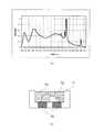
実施例1に用いる分光測色器の概略図を図1(a)、図1(b)に示す。図1(a)の分光測色器10は、可視光全体にわたる発光波長分布を有する白色光源12、集光レンズ17、反射型回折格子18、電荷蓄積型ラインセンサ(以下、単にラインセンサという)11を有する。更に、測定手段である分光測色器10は、センサの開口13から侵入する塵埃や紙粉等からの保護を目的とした保護ガラス19を有する。白色光源12から発せられた光15は、開口13及び保護ガラス19を通過する。光15は、記録材P上に形成された被測色物14(例えば、後述するパッチ画像T)に対し約45°の角度で入射し、被測色物14の光吸収特性に応じた散乱光となる。集光レンズ17の集光領域範囲内にある散乱光16の一部は、集光レンズ17に取り込まれて平行光となった後、反射型回折格子18に入射角0°で入射し、分光される。分光された分散光は、ラインセンサ11に入射する。
[Configuration of spectrophotometer]
Schematic diagrams of the spectrocolorimeter used in Example 1 are shown in FIGS. 1 (a) and 1 (b). Thespectrocolorimeter 10 in FIG. 1A includes awhite light source 12, a condensinglens 17, areflective diffraction grating 18, and a charge storage line sensor (hereinafter simply referred to as a line sensor) having an emission wavelength distribution over the entire visible light. 11. Further, thespectrocolorimeter 10 as a measuring means has aprotective glass 19 for the purpose of protection from dust, paper dust and the like entering from theopening 13 of the sensor. The light 15 emitted from thewhite light source 12 passes through theopening 13 and theprotective glass 19. The light 15 is incident at an angle of about 45 ° with respect to the measured color object 14 (for example, a patch image T described later) formed on the recording material P, and is scattered according to the light absorption characteristics of the measuredcolor object 14. It becomes light. A part of the scatteredlight 16 within the condensing region range of the condensinglens 17 is taken into the condensinglens 17 and becomes parallel light, and then enters thereflective diffraction grating 18 at an incident angle of 0 °. Is done. The dispersed light separated is incident on theline sensor 11.

図1(b)に示すように、本実施例のラインセンサ11は、波長が約350nmから約750nmの可視光を約3nm単位で検出するために必要な134画素で構成されている。なお、図1(b)には、各画素を識別するために、各画素のアドレス番号として1、2、・・・、134のように番号を付している。ラインセンサ11に入射される光は、反射型回折格子18により分光されているため、ラインセンサ11の各画素は、入射光の各波長に対応していることとなる。ラインセンサ11は、入射した分散光の強度に応じて、各画素で光電荷を蓄積する。そして制御演算部22の制御により、ラインセンサ11の蓄積電荷は電圧に変換され、順次電圧信号として出力される。そして、出力された電圧信号をAD変換器21によってAD変換することにより、制御演算部22は被測色物14からの反射光を画素毎のデジタル信号として得ることができる。本実施例に用いたラインセンサ11は、電荷蓄積型ラインセンサであり、所定の蓄積時間に入射した分散光の強度に応じて、画素毎に電圧信号を出力する。また、ラインセンサ11の蓄積時間は、制御演算部22によって適宜調整することが可能である。また、分光測色器10の対向部には、分光測色器10の補正用として白色の基準板(以下、白基準板とする)20が配置されている。従って、分光測色器10により測定される被測色物14としては、記録材P上に形成された後述するパッチ画像Tが相当する場合と、白基準板20が相当する場合とがある。  As shown in FIG. 1B, theline sensor 11 of the present embodiment is composed of 134 pixels necessary for detecting visible light having a wavelength of about 350 nm to about 750 nm in units of about 3 nm. In FIG. 1B, numbers such as 1, 2,..., 134 are assigned as the address numbers of the pixels in order to identify the pixels. Since the light incident on theline sensor 11 is dispersed by the reflectiontype diffraction grating 18, each pixel of theline sensor 11 corresponds to each wavelength of the incident light. Theline sensor 11 accumulates photoelectric charges in each pixel according to the intensity of the incident dispersed light. Under the control of thecontrol calculation unit 22, the accumulated charge of theline sensor 11 is converted into a voltage and sequentially output as a voltage signal. Then, the output voltage signal is AD converted by theAD converter 21 so that thecontrol calculation unit 22 can obtain the reflected light from thecolor object 14 as a digital signal for each pixel. Theline sensor 11 used in the present embodiment is a charge accumulation type line sensor, and outputs a voltage signal for each pixel according to the intensity of dispersed light incident during a predetermined accumulation time. Further, the accumulation time of theline sensor 11 can be appropriately adjusted by thecontrol calculation unit 22. Further, a white reference plate (hereinafter, referred to as a white reference plate) 20 is disposed at a facing portion of thespectrocolorimeter 10 for correction of thespectrocolorimeter 10. Therefore, the measuredobject 14 measured by thespectrocolorimeter 10 may correspond to a patch image T (described later) formed on the recording material P or awhite reference plate 20.

[被測色物の分光反射率Or(λ)の求め方]
ラインセンサ11から出力される各画素のデジタル信号は、AD変換器21によりAD変換されて制御演算部22に入力され、制御演算部22において以下の演算がなされる。ラインセンサ11の各画素について、各画素のアドレス番号n(本実施例では、n=1〜134)(図1(b)参照)と、各画素に対応する光の波長λとが、予め相対的に対応付けられている(以下、値付けと記す)。そして、互いに対応付けられた(即ち、値付けがなされた)各画素のアドレス番号nと波長λは、メモリ部23に保持されている。なお、値付けの作業は、例えばラインセンサ11の出荷時に波長λが既知の基準単一波長スペクトルを用いるなどして、従来公知の方法にて行うことができる。このようにラインセンサ11の各画素と波長λが対応付けられることで、上述したラインセンサ11の画素毎の電圧信号出力によって、被測色物14からの反射光の波長−信号強度スペクトルOi(λ)が得られる。
[How to Obtain Spectral Reflectance Or (λ) of Colored Object]
The digital signal of each pixel output from theline sensor 11 is AD converted by theAD converter 21 and input to thecontrol calculation unit 22, and thecontrol calculation unit 22 performs the following calculation. For each pixel of theline sensor 11, the address number n of each pixel (in this embodiment, n = 1 to 134) (see FIG. 1B) and the wavelength of light λ corresponding to each pixel are in advance relative to each other. (Hereinafter referred to as pricing). Then, the address number n and the wavelength λ of each pixel associated with each other (that is, priced) are held in thememory unit 23. The pricing operation can be performed by a conventionally known method, for example, by using a reference single wavelength spectrum whose wavelength λ is known when theline sensor 11 is shipped. Thus, by associating each pixel of theline sensor 11 with the wavelength λ, the wavelength-signal intensity spectrum Oi () of the reflected light from the color to be measured 14 is generated by the voltage signal output for each pixel of theline sensor 11 described above. λ) is obtained.

ここで、予め測定された分光反射率が既知の基準試料(一般には白色の基準試料、以下、白基準ともいう)に、白色光源12の光を照射したときの反射光の波長−信号強度スペクトルをWi(λ)とする。Wi(λ)は、分光測色器10により白基準を測色(測定ともいう)したときのスペクトルで、保護ガラス19に汚れが付着している場合には汚れも含まれた状態で測定されたときのスペクトルである。また、基準試料自身が有する波長−信号強度スペクトルをWr(λ)とする。Wr(λ)は、汚れ等がない理想的な環境で厳密に測定された白基準のスペクトルである。更に、被測色物14の分光反射率をOr(λ)とする。そうすると、被測色物14の分光反射率Or(λ)は、次式により求められる。
Or(λ)={Oi(λ)/Wi(λ)}×Wr(λ)・・・式(1)
更に、制御演算部22は、式(1)から得られた被測色物14の分光反射率Or(λ)を元に、380nmから730nmの範囲の分光反射率を10nm毎に補間演算して外部(例えば、後述する制御部55;図1(c)参照)へ出力する。
Here, the wavelength-signal intensity spectrum of reflected light when a preliminarily measured reference sample with known spectral reflectance (generally a white reference sample, hereinafter also referred to as a white reference) is irradiated with light from thewhite light source 12. Is Wi (λ). Wi (λ) is a spectrum when the white color is measured (also referred to as measurement) by thespectrocolorimeter 10, and is measured in a state where dirt is included when theprotective glass 19 is dirty. It is a spectrum at the time. Further, the wavelength-signal intensity spectrum of the reference sample itself is defined as Wr (λ). Wr (λ) is a white reference spectrum measured strictly in an ideal environment free from dirt and the like. Furthermore, let the spectral reflectance of thecolor object 14 be Or (λ). Then, the spectral reflectance Or (λ) of the measuredobject 14 is obtained by the following equation.
Or (λ) = {Oi (λ) / Wi (λ)} × Wr (λ) (1)
Further, thecontrol calculation unit 22 interpolates the spectral reflectance in the range of 380 nm to 730 nm for every 10 nm based on the spectral reflectance Or (λ) of the measuredobject 14 obtained from the equation (1). The data is output to the outside (for example, acontrol unit 55 described later; see FIG. 1C).

本実施例の分光測色器10により被測色物14を測定するにあたっては、まず制御演算部22が、式(1)に示された波長λを画素アドレスnに置き換える(Or(n)={Oi(n)/Wi(n)}×Wr(n))。そして、制御演算部22は、予め測定しておいた白基準の出力信号Wi(n)と、被測色物14を測定した際のラインセンサ11からの出力信号Oi(n)とから、各画素についてOi(n)/Wi(n)を演算する。ここで、予め測定しておいた白基準の出力信号Wi(n)とは、後述する図6のS118の処理で求められる値である(図8、図9も同様)。その後、対応付けしたラインセンサ11の各画素nと波長λの関係をメモリ部23から読み出し、画素アドレスnを波長λに置き換えてOi(λ)/Wi(λ)を得る。そして、制御演算部22は、メモリ部23に記憶されているWr(λ)の値を読み出し、式(1)に従って、被測色物14の分光反射率Or(λ)を得ることができる。即ち、分光測色器10により被測色物14を測定すると、制御演算部22が、ラインセンサ11の出力信号Oi(n)を白基準の測定値Wi(n)に基づいて補正することにより、分光反射率Or(λ)を外部に出力する。  In measuring thecolor measurement object 14 using thespectrocolorimeter 10 of the present embodiment, thecontrol calculation unit 22 first replaces the wavelength λ shown in Equation (1) with the pixel address n (Or (n) = {Oi (n) / Wi (n)} × Wr (n)). Then, thecontrol calculation unit 22 calculates each of the white reference output signal Wi (n) measured in advance and the output signal Oi (n) from theline sensor 11 when the measuredcolor object 14 is measured. Oi (n) / Wi (n) is calculated for the pixel. Here, the white reference output signal Wi (n) measured in advance is a value obtained in the process of S118 of FIG. 6 described later (the same applies to FIGS. 8 and 9). Thereafter, the relationship between each pixel n of the associatedline sensor 11 and the wavelength λ is read from thememory unit 23, and the pixel address n is replaced with the wavelength λ to obtain Oi (λ) / Wi (λ). And thecontrol calculating part 22 can read the value of Wr ((lambda)) memorize | stored in thememory part 23, and can obtain the spectral reflectance Or ((lambda)) of the to-be-measured object 14 according to Formula (1). That is, when thecolor measurement object 14 is measured by thespectrocolorimeter 10, thecontrol calculation unit 22 corrects the output signal Oi (n) of theline sensor 11 based on the white reference measurement value Wi (n). The spectral reflectance Or (λ) is output to the outside.

[カラー画像形成装置の構成]
本実施例の分光測色器10は、例えば電子写真方式のカラー画像形成装置で用いられることが可能であり、図1(c)はその一例である中間転写ベルトを採用したタンデム方式のカラー画像形成装置を示す構成図である。なお、後述する分光測色器10を適用可能なカラー画像形成装置としては、電子写真方式のカラー画像形成装置に限定されるものではなく、例えばインクジェット方式やその他の方式のカラー画像形成装置であってもよい。図1(c)を用いて本実施例の画像形成装置の画像形成部の動作を説明する。
[Configuration of color image forming apparatus]
Thespectral colorimeter 10 of this embodiment can be used in, for example, an electrophotographic color image forming apparatus, and FIG. 1C shows a tandem color image employing an intermediate transfer belt as an example. It is a block diagram which shows a forming apparatus. The color image forming apparatus to which thespectrocolorimeter 10 described later can be applied is not limited to an electrophotographic color image forming apparatus, but may be, for example, an inkjet type or other type of color image forming apparatus. May be. The operation of the image forming unit of the image forming apparatus according to the present exemplary embodiment will be described with reference to FIG.

画像形成部は、給紙カセット44、YMCK各色のステーション毎の感光体(以下、感光ドラムという)31Y、31M、31C、31K、帯電手段としての帯電ローラ32Y、32M、32C、32Kを備える。また、画像形成部は、露光用スキャナ部33Y、33M、33C、33K、現像手段としての現像器38Y、38M、38C、38Kを備える。また、画像形成部は、中間転写ベルト37、中間転写ベルト37を駆動する駆動ローラ41、張架ローラ40、補助ローラ42、一次転写ローラ34Y、34M、34C、34Kを備える。更に、画像形成部は、二次転写ローラ43、定着部51、これらを制御動作させる制御部55、コントローラ部56等を備える。なお、符号の添え字Yはイエロー色、Mはマゼンタ色、Cはシアン色、Kはブラック色をそれぞれ表しており、以降、必要な場合を除きYMCKは省略する。感光ドラム31は、アルミシリンダの外周に有機光導伝層を塗布して構成し、図示しない駆動モータの駆動力が伝達されて回転する。駆動モータは、感光ドラム31を画像形成動作に応じて時計周り方向(図1(c)中矢印方向)に回転させる。  The image forming unit includes apaper feed cassette 44, photosensitive members (hereinafter referred to as photosensitive drums) 31Y, 31M, 31C, and 31K for each color YMCK station, and chargingrollers 32Y, 32M, 32C, and 32K as charging means. The image forming unit includesexposure scanner units 33Y, 33M, 33C, and 33K, and developingunits 38Y, 38M, 38C, and 38K as developing units. The image forming unit includes anintermediate transfer belt 37, a drivingroller 41 that drives theintermediate transfer belt 37, a stretchingroller 40, anauxiliary roller 42, andprimary transfer rollers 34Y, 34M, 34C, and 34K. Further, the image forming unit includes a secondary transfer roller 43, a fixingunit 51, acontrol unit 55 for controlling these, acontroller unit 56, and the like. Note that the subscript Y of the code represents yellow, M represents magenta, C represents cyan, and K represents black. YMCK will be omitted unless necessary. The photosensitive drum 31 is configured by applying an organic optical transmission layer on the outer periphery of an aluminum cylinder, and rotates when a driving force of a driving motor (not shown) is transmitted. The drive motor rotates the photosensitive drum 31 in the clockwise direction (the arrow direction in FIG. 1C) according to the image forming operation.

制御部55が画像信号を受信すると、記録材Pは、給紙カセット44等から給紙ローラ45、46によって画像形成装置内に給紙される。そして、記録材Pは、後述の画像形成動作と記録材Pの搬送との同期をとるためのローラ状同期回転体であるレジストローラ対47に一旦挟持され、停止して待機する。一方、コントローラ部56は、受信した画像信号に応じて、露光用スキャナ部33によって帯電ローラ32の作用により一定電位に帯電された感光ドラム31の表面に静電潜像を形成させる。現像器38は静電潜像を可視化する手段であり、ステーション毎にイエロー(Y)、マゼンダ(M)、シアン(C)、ブラック(K)の現像を行う。各現像器38には、スリーブ35が設けられており、静電潜像を可視化するための現像電圧が印加されている。このように、各感光ドラム31の表面に形成された静電潜像は、現像器38の作用により単色トナー像として現像される。感光ドラム31、帯電ローラ32、現像器38は一体構成となっており、画像形成装置本体から脱着可能なトナーカートリッジ39の形態で取り付けられている。  When thecontrol unit 55 receives the image signal, the recording material P is fed into the image forming apparatus by thepaper feed rollers 45 and 46 from thepaper feed cassette 44 or the like. The recording material P is once sandwiched between a pair ofregistration rollers 47 that is a roller-like synchronous rotating body for synchronizing the image forming operation described later and the conveyance of the recording material P, and stops and waits. On the other hand, thecontroller unit 56 forms an electrostatic latent image on the surface of the photosensitive drum 31 charged to a constant potential by the exposure scanner unit 33 by the action of the charging roller 32 in accordance with the received image signal. The developing unit 38 is a means for visualizing the electrostatic latent image, and develops yellow (Y), magenta (M), cyan (C), and black (K) for each station. Each developing device 38 is provided with a sleeve 35 to which a developing voltage for visualizing the electrostatic latent image is applied. As described above, the electrostatic latent image formed on the surface of each photosensitive drum 31 is developed as a single-color toner image by the action of the developing device 38. The photosensitive drum 31, the charging roller 32, and the developing device 38 are integrated, and are attached in the form of a toner cartridge 39 that is detachable from the main body of the image forming apparatus.

中間転写ベルト37は、感光ドラム31Y、31M、31C、31Kに接触しており、カラー画像形成時に反時計周り方向に感光ドラム31Y、31M、31C、31Kの回転と同期して回転する。各感光ドラム31上で現像された単色トナー像は、一次転写ローラ34に印加された一次転写電圧の作用により中間転写ベルト37に順次重畳して転写され、中間転写ベルト37上で多色トナー像となる。その後、中間転写ベルト37上に形成された多色トナー像は、駆動ローラ41と二次転写ローラ43とで形成される二次転写ニップ部に搬送される。一方、レジストローラ対47に挟持された状態で待機していた記録材Pは、レジストローラ対47の作用により中間転写ベルト37上の多色トナー像と同期を取りながら二次転写ニップ部に搬送される。そして、中間転写ベルト37上の多色トナー像が二次転写ローラ43に印加された二次転写電圧の作用により、記録紙P上に一括転写される。  Theintermediate transfer belt 37 is in contact with thephotosensitive drums 31Y, 31M, 31C, and 31K, and rotates counterclockwise in synchronization with the rotation of thephotosensitive drums 31Y, 31M, 31C, and 31K when forming a color image. The single-color toner images developed on the respective photosensitive drums 31 are sequentially superimposed and transferred onto theintermediate transfer belt 37 by the action of the primary transfer voltage applied to the primary transfer roller 34, and the multi-color toner image is transferred onto theintermediate transfer belt 37. It becomes. Thereafter, the multicolor toner image formed on theintermediate transfer belt 37 is conveyed to a secondary transfer nip portion formed by thedrive roller 41 and the secondary transfer roller 43. On the other hand, the recording material P that has been waiting while being sandwiched between theregistration roller pair 47 is conveyed to the secondary transfer nip portion while being synchronized with the multicolor toner image on theintermediate transfer belt 37 by the action of theregistration roller pair 47. Is done. Then, the multicolor toner image on theintermediate transfer belt 37 is collectively transferred onto the recording paper P by the action of the secondary transfer voltage applied to the secondary transfer roller 43.

定着部51は、記録材Pを搬送させながら、記録材P上に転写された多色トナー像を溶融定着させる。定着部51は、記録材Pを加熱する定着ローラ51aと記録材Pを定着ローラ51aに圧接させるための加圧ローラ51bを備えている。定着ローラ51aは中空状に形成され、内部にヒータ51ahが内蔵されている。多色トナー像を保持した記録材Pは、定着ローラ51aと加圧ローラ51bにより搬送されるとともに、熱及び圧力を加えられ、トナーが記録材P表面に定着される。  The fixingunit 51 melts and fixes the multicolor toner image transferred onto the recording material P while conveying the recording material P. The fixingunit 51 includes a fixingroller 51a that heats the recording material P and a pressure roller 51b that presses the recording material P against the fixingroller 51a. The fixingroller 51a is formed in a hollow shape, and a heater 51ah is incorporated therein. The recording material P holding the multicolor toner image is conveyed by the fixingroller 51a and the pressure roller 51b, and heat and pressure are applied to fix the toner on the surface of the recording material P.

トナー像定着後の記録材Pは、排紙ローラ50によって排紙トレイ52に排出され、片面印字の場合には画像形成動作を終了する。一方、両面印字の場合には、記録紙Pの2面目への画像形成を行うために、排紙部でのスイッチバック動作によって両面搬送路60を経由して、再びレジストローラ対47に一旦挟持されて停止して待機する。その後、上述した一連の画像形成動作が行われて記録材Pの2面目への画像形成が行われる。クリーニング装置48は、中間転写ベルト37上に残留したトナーをクリーニングする。クリーニング装置48によりクリーニングが行われ回収されたトナーは、クリーナ容器49に蓄えられる。  The recording material P after the toner image is fixed is discharged to apaper discharge tray 52 by apaper discharge roller 50, and in the case of single-sided printing, the image forming operation is finished. On the other hand, in the case of double-sided printing, in order to form an image on the second side of the recording paper P, the paper is once sandwiched between theregistration roller pair 47 via the double-sided conveyance path 60 by the switchback operation in the paper discharge unit. Stop and wait. Thereafter, the series of image forming operations described above is performed, and image formation is performed on the second surface of the recording material P. Thecleaning device 48 cleans the toner remaining on theintermediate transfer belt 37. The toner that has been cleaned and collected by thecleaning device 48 is stored in acleaner container 49.

本実施例の分光測色器10は、記録材Pに指定間隔及び形状で形成された測定対象のトナー画像(以下、トナーパッチと記す)を測色する目的で、両面搬送路60中の長手中央位置に配置されている。詳細には、両面搬送路60において、記録紙Pの搬送方向に直交する方向の中央部に配置されている。なお、分光測色器10の配置は、長手方向中央位置に限定されない。また、分光測色器10により測色されるトナーパッチは、分光測色器10の位置に応じて記録材P上に形成されるものとする。更に、分光測色器10は、記録材P上のトナーパッチの定着処理が終了したあとで、記録材Pが画像形成装置外に排出される前にトナーパッチを測定できる位置に配置されていればよい。分光測色器10によるトナーパッチの測色動作が開始されると、まず初めに前述した一連の画像形成動作により、記録材Pに例えば図2(a)に示す測色用のパッチ画像Tが形成される。図2(a)に示すように、トナーパッチとしてのパッチ画像Tは、記録紙Pの搬送方向に階調の異なるパッチが連続して形成された形状をしている。パッチ画像Tにおいて、記録紙Pの搬送方向の先頭に位置するパッチをトリガーパッチ(図2(a)中、Triggerと図示)ということとする。なお、パッチ画像Tのトリガーパッチは、後述する迷光補正に用いられるとともに、測色タイミングを検知するためのトリガーとしての機能も有する。また、符号Bについては実施例3で説明する。  Thespectrocolorimeter 10 according to the present embodiment is provided with a longitudinal length in the double-sided conveyance path 60 for the purpose of measuring the color of a measurement target toner image (hereinafter referred to as a toner patch) formed on the recording material P with a specified interval and shape. Located in the center position. Specifically, the double-sided conveyance path 60 is disposed at the center in the direction orthogonal to the conveyance direction of the recording paper P. The arrangement of thespectrocolorimeter 10 is not limited to the longitudinal center position. Further, the toner patches measured by thespectrocolorimeter 10 are formed on the recording material P in accordance with the position of thespectrocolorimeter 10. Further, thespectrocolorimeter 10 is arranged at a position where the toner patch can be measured after the fixing process of the toner patch on the recording material P is completed and before the recording material P is discharged out of the image forming apparatus. That's fine. When the color measurement operation of the toner patch by thespectrocolorimeter 10 is started, first, for example, the color measurement patch image T shown in FIG. It is formed. As shown in FIG. 2A, the patch image T as a toner patch has a shape in which patches having different gradations are continuously formed in the conveyance direction of the recording paper P. In the patch image T, the patch positioned at the head in the transport direction of the recording paper P is referred to as a trigger patch (shown as Trigger in FIG. 2A). The trigger patch of the patch image T is used for stray light correction described later and also has a function as a trigger for detecting the colorimetric timing. Reference numeral B will be described in a third embodiment.

定着部51を通過した記録材Pは、排紙部でのスイッチバック動作によって両面搬送路60へと搬送される。そして、両面搬送路60中に配置された分光測色器10により、記録紙Pに形成されたパッチ画像Tは、トリガーパッチを基準として、記録材Pの搬送と同期しながら順次測色される。分光測色器10による測色が終了し、レジストローラ対47を通過した記録材Pは、二次転写部、定着部51を通過して排紙ローラ50によって排紙トレイ52に排出される。このような一連の画像形成動作は、画像形成装置内に設けられた制御部55によって制御される。  The recording material P that has passed through the fixingunit 51 is conveyed to the double-sided conveyance path 60 by a switchback operation in the paper discharge unit. Then, thespectrocolorimeter 10 arranged in the double-sided conveyance path 60 sequentially measures the color of the patch image T formed on the recording paper P in synchronization with the conveyance of the recording material P with reference to the trigger patch. . After the colorimetry by thespectrocolorimeter 10 is completed, the recording material P that has passed through theregistration roller pair 47 passes through the secondary transfer portion and the fixingportion 51 and is discharged to thedischarge tray 52 by thedischarge roller 50. Such a series of image forming operations is controlled by acontrol unit 55 provided in the image forming apparatus.

[画像形成動作]
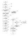
次に、本実施例の画像形成装置における画像形成動作の一例を、図2(b)に示すブロック図を用いて説明する。画像形成装置のコントローラ部56と制御部55は、不図示のビデオインターフェースを介して接続され、コントローラ部56が外部端末のホストコンピュータ57や不図示のネットワークに接続される。コントローラ部56が有する記憶部には、色変換に用いるカラーマッチングテーブル(CM)、色分解テーブル(C1)、濃度補正テーブル(D)が記憶されている。また、制御部55には、画像形成動作や分光測色器10からの測色結果を処理するCPU202と、分光測色器10による測定結果を一時保管するメモリ203が搭載されている。
[Image forming operation]
Next, an example of an image forming operation in the image forming apparatus of this embodiment will be described with reference to a block diagram shown in FIG. Thecontroller unit 56 and thecontrol unit 55 of the image forming apparatus are connected via a video interface (not shown), and thecontroller unit 56 is connected to ahost computer 57 of an external terminal or a network (not shown). The storage unit included in thecontroller unit 56 stores a color matching table (CM), a color separation table (C1), and a density correction table (D) used for color conversion. In addition, thecontrol unit 55 includes aCPU 202 that processes an image forming operation and color measurement results from thespectrocolorimeter 10, and amemory 203 that temporarily stores measurement results obtained by thespectrocolorimeter 10.

画像形成動作が開始されると、コントローラ部56は、以下の処理を行う。コントローラ部56は、予め用意されているカラーマッチングテーブル(CM)により、ホストコンピュータ等から送られてくる画像の色を表すRGB信号を、カラー画像形成装置の色再現域に合わせたデバイスRGB信号に変換する。以降、カラー画像形成装置の色再現域に合わせたデバイスRGB信号を、DevRGB信号と表記する。続いて、コントローラ部56は、色分解テーブル(C1)及び後述するカラー補正テーブル(C2)により、DevRGB信号をカラー画像形成装置のトナー色材色であるCMYK信号に変換する。なお、カラー補正テーブル(C2)は、後述する本実施例の測色動作によって、テーブルのデータが更新されるものである。  When the image forming operation is started, thecontroller unit 56 performs the following processing. Thecontroller unit 56 converts the RGB signal representing the color of the image sent from the host computer or the like into a device RGB signal that matches the color gamut of the color image forming apparatus using a color matching table (CM) prepared in advance. Convert. Hereinafter, the device RGB signal matched with the color gamut of the color image forming apparatus is referred to as DevRGB signal. Subsequently, thecontroller unit 56 converts the DevRGB signal into a CMYK signal that is a toner color material color of the color image forming apparatus, using the color separation table (C1) and a color correction table (C2) described later. In the color correction table (C2), the data of the table is updated by the color measurement operation of the present embodiment described later.

そして、コントローラ部56は、各々のカラー画像形成装置に固有の階調‐濃度特性を補正する濃度補正テーブル(D)により、CMYK信号を、階調‐濃度特性の補正を加えたC’M’Y’K’信号へ変換する。そして、コントローラ部56は、ハーフトーン処理を行い、C’M’Y’K’信号をC’’M’’Y’’K’’信号へ変換する。その後、コントローラ部56は、PWM(Pulse Width Modulation)テーブル(PW)により、C’’M’’Y’’K’’信号を、露光時間Tc、Tm、Ty、Tkへ変換する。ここで、露光時間Tc、Tm、Ty、Tkは、C’’M’’Y’’K’’信号に対応する露光用スキャナ部33C、33M、33Y、33Kの露光時間である。コントローラ部56は、これら露光時間Tc、Tm、Ty、Tkに従って、露光用スキャナ部33C、33M、33Y、33Kを制御する。これにより、コントローラ部56は、感光ドラム31C、31M、31Y、31Kの表面に静電潜像を形成し、先に述べた一連の画像形成動作が行われる。  Then, thecontroller unit 56 uses the density correction table (D) for correcting the tone-density characteristics specific to each color image forming apparatus to convert the CMYK signal into C′M ′ with the tone-density characteristics corrected. Convert to Y'K 'signal. Then, thecontroller unit 56 performs halftone processing and converts the C′M′Y′K ′ signal into a C ″ M ″ Y ″ K ″ signal. Thereafter, thecontroller unit 56 converts the C ″ M ″ Y ″ K ″ signal into exposure times Tc, Tm, Ty, and Tk by using a PWM (Pulse Width Modulation) table (PW). Here, the exposure times Tc, Tm, Ty, and Tk are exposure times of theexposure scanner units 33C, 33M, 33Y, and 33K corresponding to the C ″ ″ M ″ Y ″ K ″ signal. Thecontroller unit 56 controls theexposure scanner units 33C, 33M, 33Y, and 33K according to the exposure times Tc, Tm, Ty, and Tk. As a result, thecontroller unit 56 forms electrostatic latent images on the surfaces of thephotosensitive drums 31C, 31M, 31Y, and 31K, and the series of image forming operations described above are performed.

また、分光測色器10によるパッチ画像Tの測色動作においては、図2(a)に示すように、記録材Pに測色用のパッチ画像Tが形成される。この際、コントローラ部56は、予めコントローラ部56に格納されている複数個のCMYK形式のカラーパッチデータ(CPD)に従って、パッチ画像Tを形成する。パッチ画像Tは単色のパッチでも混色のパッチでもよい。記録材P上に形成された測色用のパッチ画像Tは、前述したように分光測色器10で測色される。そして、分光測色器10のラインセンサ11により読み取られたデータ(上述したOi(n))に基づき、それぞれのパッチ毎に制御演算部22によって分光反射率Or(λ)が算出され、制御部55に出力される。  Further, in the colorimetric operation of the patch image T by thespectrocolorimeter 10, the colorimetric patch image T is formed on the recording material P as shown in FIG. At this time, thecontroller unit 56 forms a patch image T in accordance with a plurality of CMYK format color patch data (CPD) stored in thecontroller unit 56 in advance. The patch image T may be a single color patch or a mixed color patch. The colorimetric patch image T formed on the recording material P is measured by thespectrocolorimeter 10 as described above. Based on the data read by theline sensor 11 of the spectrocolorimeter 10 (Oi (n) described above), the spectral reflectance Or (λ) is calculated by thecontrol calculation unit 22 for each patch, and thecontrol unit 55 is output.

分光測色器10により出力された分光反射率Or(λ)のデータは、制御部55の作用によって色度値(例えばCIE L*a*b*など)に変換されてコントローラ部56の色変換部に送信される。そして、コントローラ部56の色変換部は、不図示のカラーマネージメントシステム(Color Management System:CMS)を利用して、制御部55から送信された色度値(L*a*b)を、CMYK形式のデータ(CSD)に変換する。ここで、CMYK形式のデータ(CSD)は、画像形成装置に依存するデータである。その後、コントローラ部56の色変換部は、変換したCMYKデータ(CSD)と、デフォルトのカラーパッチデータ(CPD)とを比較する。これにより、コントローラ部56は、変換したCMYKデータ(CSD)とデフォルトのカラーパッチデータ(CPD)との差を補正するようなカラー補正テーブル(C2)を生成し、更新する。  The spectral reflectance Or (λ) data output from thespectrocolorimeter 10 is converted into a chromaticity value (for example, CIE L * a * b *) by the operation of thecontrol unit 55, and the color conversion of thecontroller unit 56 is performed. Sent to the department. The color conversion unit of thecontroller unit 56 uses the color management system (CMS) (not shown) to convert the chromaticity value (L * a * b) transmitted from thecontrol unit 55 into the CMYK format. Data (CSD). Here, the CMYK format data (CSD) is data depending on the image forming apparatus. Thereafter, the color conversion unit of thecontroller unit 56 compares the converted CMYK data (CSD) with the default color patch data (CPD). Accordingly, thecontroller unit 56 generates and updates a color correction table (C2) that corrects the difference between the converted CMYK data (CSD) and the default color patch data (CPD).

これらの処理は、測色された全ての測色用のパッチ画像Tに対して行われるが、測色されるパッチ画像Tは、画像形成装置で再現可能な全ての色を必ずしも揃えている必要はない。測色用のパッチ画像Tとして記録材Pに形成されていないCMYKデータに関しては、測色されたパッチ画像Tに基づいて補間処理を行うことにより、カラー補正テーブル(C2)を作成すればよい。このようにして作成されたカラー補正テーブル(C2)は、色分解テーブル(C1)と共に、コントローラ部56において更新、保持される。  These processes are performed on all the colorimetric patch images T that have been colorimetrically measured. However, the colorimetric patch images T need not necessarily have all colors that can be reproduced by the image forming apparatus. There is no. For CMYK data that is not formed on the recording material P as a colorimetric patch image T, a color correction table (C2) may be created by performing interpolation processing based on the colorimetric patch image T. The color correction table (C2) created in this way is updated and held in thecontroller unit 56 together with the color separation table (C1).

[分光測色器に用いられる白色光源]
次に、本実施例において、分光測色器10により測色する際に用いられる白色光源12について詳細に説明する。分光測色器10により印刷物や物体色を測色するにあたっては、例えばJIS Z8722に記載されているように、次のように測定を行うことが望まれる。即ち、分光測色器10により厳密に測色を行う際には、波長380nmから780nmの波長域、簡易的な測色の場合でも波長400nmから700nmの波長域に対して、その強度を測定することが望まれる。
[White light source used in spectrocolorimeter]
Next, in the present embodiment, thewhite light source 12 used for color measurement by thespectrocolorimeter 10 will be described in detail. In measuring the color of a printed matter or object color with thespectrocolorimeter 10, it is desired to perform the following measurement as described in, for example, JIS Z8722. That is, when the colorimetry is strictly performed by thespectrocolorimeter 10, the intensity is measured in the wavelength range of 380 nm to 780 nm, and even in the case of simple colorimetry, the wavelength range of 400 nm to 700 nm. It is desirable.

そこで、本実施例では、白色光源12として、図3(a)に示すような発光スペクトルを持つLEDパッケージ等の光源を用いる。ここで、図3(a)の横軸は波長(nm)、縦軸は相対強度を示す。図3(a)に示すように、本実施例の白色光源12は、波長390nmに発光強度の極大値を持つ発光ダイオードのスペクトルと、青色スペクトルと、黄色スペクトルと、赤色スペクトルとを組み合わせた形状となっている。ここで、青色スペクトルは波長450nmに蛍光強度の極大値を持ち、黄色スペクトルは波長570nmに蛍光強度の極大値を持ち、赤色スペクトルは波長630nmに蛍光強度の極大値を持つ。なお、このような発光スペクトルを持つLEDパッケージは、従来公知のパッケージと同様に、発光チップと蛍光体を組み合わせることで、表面実装型、砲弾型、チップオンボード型など、任意の形状タイプで得ることが可能である。  Therefore, in this embodiment, a light source such as an LED package having an emission spectrum as shown in FIG. Here, the horizontal axis of FIG. 3A indicates the wavelength (nm), and the vertical axis indicates the relative intensity. As shown in FIG. 3 (a), thewhite light source 12 of this embodiment is a combination of a spectrum of a light emitting diode having a maximum value of emission intensity at a wavelength of 390 nm, a blue spectrum, a yellow spectrum, and a red spectrum. It has become. Here, the blue spectrum has a maximum fluorescence intensity at a wavelength of 450 nm, the yellow spectrum has a maximum fluorescence intensity at a wavelength of 570 nm, and the red spectrum has a maximum fluorescence intensity at a wavelength of 630 nm. In addition, the LED package having such an emission spectrum can be obtained in any shape type such as a surface mount type, a shell type, a chip-on-board type, etc. by combining a light emitting chip and a phosphor, similarly to a conventionally known package. It is possible.

LEDパッケージの代表例として、図3(b)に表面実装型LEDパッケージの模式構造図を示す。表面実装型LEDパッケージは、セラミックや樹脂などで成型したキャビティ71の中に発光ダイオード72を実装し、キャビティ71に蛍光体を分散させたエポキシやシリコーンなどの樹脂73を封入して得られる。電極74を介して発光ダイオード72に電流が供給されると、発光ダイオード72から自身の持つ固有波長スペクトルが放射される。放射されたスペクトルの一部は、キャビティ71内の蛍光体を励起し、蛍光体の持つ固有波長スペクトルが放射される。蛍光体として先に述べた青色、黄色、赤色の各波長の光を放射するものを使用することで、本実施例に用いられる図3(a)に示されるような発光スペクトルが放射される。  As a typical example of an LED package, FIG. 3B shows a schematic structural diagram of a surface mount LED package. The surface mount type LED package is obtained by mounting alight emitting diode 72 in acavity 71 molded of ceramic or resin, and encapsulating aresin 73 such as epoxy or silicone in which a phosphor is dispersed in thecavity 71. When a current is supplied to thelight emitting diode 72 via theelectrode 74, the intrinsic wavelength spectrum of thelight emitting diode 72 is emitted. Part of the emitted spectrum excites the phosphor in thecavity 71, and the intrinsic wavelength spectrum of the phosphor is emitted. By using the phosphor that emits light of each wavelength of blue, yellow, and red described above, an emission spectrum as shown in FIG. 3A used in this embodiment is emitted.

このように、本実施例では、白色光源12として、近紫外領域に発光強度の極大値を持つ発光ダイオードを使用したLEDパッケージを用いる構成とする。これにより、測色に必要であり、かつ一般的な白色LEDでは十分な出力を得ることのできなかった、波長400nm付近の分光反射出力を得ることが可能となる。具体的には、波長380nm又は400nm以上の波長域の出力を得るために、発光強度の極大値が波長380nmから420nmの範囲にある発光ダイオードを、励起光源として用いれば良い。このような発光ダイオードとしては、InGaN系のものが広く知られている。  Thus, in this embodiment, as thewhite light source 12, an LED package using a light emitting diode having a maximum value of light emission intensity in the near ultraviolet region is used. As a result, it is possible to obtain a spectral reflection output around a wavelength of 400 nm, which is necessary for colorimetry and cannot be obtained with a general white LED. Specifically, in order to obtain an output in a wavelength range of 380 nm or 400 nm or more, a light emitting diode having a maximum emission intensity in the range of wavelengths from 380 nm to 420 nm may be used as an excitation light source. As such a light emitting diode, an InGaN-based one is widely known.

また、白色光源12として本実施例にて例示したように、波長420nmから730nmの領域に蛍光強度の極大値を持つ複数の蛍光体を使用したLEDパッケージを用いる構成とする。これにより、簡易測色に必要とされる波長400nmから700nmの領域における分光反射出力を得ることが可能となる。この場合、使用される蛍光体の組成には特に制限はないが、酸化物蛍光体又は窒化物蛍光体が化学的に安定であるため、半導体発光素子及び照明装置の寿命が長くなるので好ましい。特に、金属酸化物、金属窒化物、リン酸塩及び硫化物に、希土類金属のイオンや金属のイオンを付活元素又は共付活元素として組み合わせたものが好ましい。ここで、金属酸化物は、Y2O3、Zn2SiO4等に代表されるものである。また、金属窒化物は、Sr2Si5N8等に代表されるものである。また、リン酸塩は、Ca5(PO4)3Cl等に代表されるものである。また、硫化物は、ZnS、SrS、CaS等に代表されるものである。また、希土類金属は、Ce、Pr、Nd、Pm、Sm、Eu、Tb、Dy、Ho、Er、Tm、Yb等である。更に、金属は、Ag、Cu、Au、Al、Mn、Sb等である。これらは青色蛍光体、緑色蛍光体、黄色蛍光体、橙色蛍光体、赤色蛍光体など、従来公知の蛍光体として用いられている組成物である。  Further, as exemplified in the present embodiment, as thewhite light source 12, an LED package using a plurality of phosphors having maximum values of fluorescence intensity in a wavelength range of 420 nm to 730 nm is used. Thereby, it is possible to obtain a spectral reflection output in a wavelength range of 400 nm to 700 nm required for simple colorimetry. In this case, the composition of the phosphor to be used is not particularly limited, but the oxide phosphor or the nitride phosphor is chemically stable, which is preferable because the lifetime of the semiconductor light emitting element and the lighting device is extended. In particular, a combination of a metal oxide, a metal nitride, a phosphate and a sulfide with a rare earth metal ion or a metal ion as an activator element or a coactivator element is preferable. Here, the metal oxide is represented by Y2O3, Zn2SiO4, or the like. The metal nitride is typified by Sr2Si5N8 or the like. The phosphate is represented by Ca5 (PO4) 3Cl. The sulfide is represented by ZnS, SrS, CaS and the like. The rare earth metal is Ce, Pr, Nd, Pm, Sm, Eu, Tb, Dy, Ho, Er, Tm, Yb or the like. Further, the metal is Ag, Cu, Au, Al, Mn, Sb or the like. These are compositions used as conventionally known phosphors such as blue phosphor, green phosphor, yellow phosphor, orange phosphor, and red phosphor.

[両面搬送路上における分光測色器の設置状況]
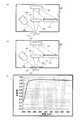
次に、定着後の両面搬送路60における分光測色器10の設置状況の詳細図を図4(a)、図4(b)に示す。図4(a)は、分光測色器10が両面搬送路60内に突出し、記録材Pを狭持搬送する状態を示している。一方、図4(b)は、両面搬送路60に対して分光測色器10が退避している様子を示している。図4(a)において分光測色器10は、測色器ホルダー112によって保持され、付勢ばね113によって測色器ホルダー112毎付勢されており、両面搬送路60内に突出している。記録材Pは、分光測色器10の表面の保護ガラス19と白基準板20(分光測色器10の対向部でもある)によって狭持される。そして、記録材Pは、不図示の搬送ローラによって搬送力を付与され、両面搬送路60を搬送方向(図4(a)中、下向きの矢印方向)に搬送され、分光測色器10を通過する。記録材Pが分光測色器10を通過している状態で、分光測色器10は、記録紙P上に形成された複数のカラーパッチからなるパッチ画像Tに同期してパッチ画像Tを読み取り、測色動作が実行される。
[Installation status of spectral colorimeter on double-sided conveyance path]
Next, detailed views of the installation state of thespectrocolorimeter 10 in the double-sided conveyance path 60 after fixing are shown in FIGS. FIG. 4A shows a state in which thespectrocolorimeter 10 protrudes into the double-sided conveyance path 60 and nipping and conveying the recording material P. On the other hand, FIG. 4B shows a state where thespectrocolorimeter 10 is retracted from the double-sided conveyance path 60. In FIG. 4A, thespectrocolorimeter 10 is held by acolorimeter holder 112, is urged for eachcolorimeter holder 112 by an urgingspring 113, and protrudes into the double-sided conveyance path 60. The recording material P is sandwiched between theprotective glass 19 on the surface of thespectrocolorimeter 10 and the white reference plate 20 (which is also the facing portion of the spectrocolorimeter 10). Then, the recording material P is given conveyance force by a conveyance roller (not shown), is conveyed in the conveyance direction (downward arrow direction in FIG. 4A) through the double-sided conveyance path 60, and passes through thespectrocolorimeter 10. To do. With the recording material P passing through thespectrocolorimeter 10, thespectrocolorimeter 10 reads the patch image T in synchronization with the patch image T composed of a plurality of color patches formed on the recording paper P. The color measurement operation is executed.

また、分光測色器10による測色動作を行わない場合には、両面搬送路60内に記録材Pが搬送される際の記録材Pの画像形成面を保護する目的で、分光測色器10は両面搬送路60から退避される。詳細には、カム部115が不図示のモータ等により回転駆動され、カム部115が測色器ホルダー112のリフトアーム部114を押上げる。そして、測色器ホルダー112のリフトアーム部114を押上げる力が付勢バネ113による付勢力に打ち勝って、分光測色器10が両面搬送路60から退避させられる。この状態を図4(b)に示す。図4(b)には、図中左向きの矢印方向(搬送方向に直交する方向)に分光測色器10が退避していく方向を示す。この状態では、両面搬送路60内面に対して測色用の窓部分である保護ガラス19が開放状態となっている様子がわかる。図4(b)の状態においては、分光測色器10の保護ガラス19表面は、記録材Pとの接触はないが、測色用の窓部分である保護ガラス19が開放状態となっているため、画像形成装置内を舞う塵埃にさらされることになる。  When the colorimetric operation by thespectrocolorimeter 10 is not performed, the spectrocolorimeter is used for the purpose of protecting the image forming surface of the recording material P when the recording material P is conveyed into the double-sided conveyance path 60. 10 is withdrawn from theduplex conveyance path 60. Specifically, thecam portion 115 is rotationally driven by a motor or the like (not shown), and thecam portion 115 pushes up thelift arm portion 114 of thecolorimeter holder 112. Then, the force that pushes up thelift arm portion 114 of thecolorimeter holder 112 overcomes the urging force of the urgingspring 113, and thespectrocolorimeter 10 is retracted from theduplex conveyance path 60. This state is shown in FIG. FIG. 4B shows a direction in which thespectrocolorimeter 10 is retracted in a leftward arrow direction (a direction orthogonal to the transport direction) in the drawing. In this state, it can be seen that theprotective glass 19 which is the color measurement window portion is open with respect to the inner surface of the double-sided conveyance path 60. In the state of FIG. 4B, the surface of theprotective glass 19 of thespectrocolorimeter 10 is not in contact with the recording material P, but theprotective glass 19 that is a colorimetric window portion is open. Therefore, the image forming apparatus is exposed to dust flying in the image forming apparatus.

また、図4(a)の状態で、記録材Pは分光測色器10の保護ガラス19の表面に接触するため、記録材Pによる保護ガラス19表面に付着した紙粉や塵埃等の清掃効果を期待できる。しかし、記録材Pを円滑に搬送しなければならないため、保護ガラス19と白基準板20を密着させ、その間に記録材Pを搬送させ、更に保護ガラス19の表面全体に記録材Pを押し当てて挟持搬送することは、記録材Pの円滑な搬送性を妨げるおそれがある。よって、接触面積を軽減した図4(c)のように、保護ガラス19表面と白基準板20は、対向部ホルダー20’でのみ分光測色器10と接触する構成(以下、この構成をギャップ構成という)にする必要がある。そのため、保護ガラス19と記録材Pとは対向部ホルダー20’の部分は接触するが、他の領域では軽接触を期待するギャップを持った構成となる。このため、保護ガラス19の表面清掃は、記録材Pの姿勢に依存することになる。即ち、記録材Pの姿勢によって、保護ガラス19が正常に清掃される場合や、清掃されずに紙粉や塵埃等が残留する場合の、両方の場合が存在することになる。  4A, since the recording material P contacts the surface of theprotective glass 19 of thespectrocolorimeter 10, the cleaning effect of the recording material P on paper dust and dust adhering to the surface of theprotective glass 19 is achieved. Can be expected. However, since the recording material P must be smoothly conveyed, theprotective glass 19 and thewhite reference plate 20 are brought into close contact with each other, the recording material P is conveyed between them, and the recording material P is pressed against the entire surface of theprotective glass 19. If nipped and conveyed, the smooth conveyance of the recording material P may be hindered. Therefore, as shown in FIG. 4C in which the contact area is reduced, the surface of theprotective glass 19 and thewhite reference plate 20 are in contact with thespectrocolorimeter 10 only in the facingportion holder 20 ′ (hereinafter, this configuration is referred to as a gap). Need to be configured). Therefore, theprotective glass 19 and the recording material P are in contact with each other at the portion of the facingportion holder 20 ′, but in other regions, the gap is expected to be light contact. For this reason, the surface cleaning of theprotective glass 19 depends on the posture of the recording material P. That is, depending on the posture of the recording material P, there are both cases where theprotective glass 19 is normally cleaned, and where paper dust and dust remain without being cleaned.

図5(a)、図5(b)に分光測色器10の保護ガラス19上の表面状態の様子を示す。なお、図1(a)で説明した構成と同じ構成には同じ符号を付し、説明を省略する。図5(a)は、保護ガラス19上に紙粉や塵埃等がない状態を示す。一方、図5(b)は、保護ガラス19上に付着した紙粉等200の状態を示す。また、図5(c)、図5(d)には、図5(a)、図5(b)の状態で取得した暗色(例えば黒色)の測定対象物の測定結果を示す。ここで、図5(c)は、図5(a)の状態で取得した測定結果で、図5(d)は、図5(b)の状態で取得した測定結果である。図5(c)、図5(d)のグラフは、横軸を波長(nm)、縦軸を反射率としている。図5(c)、図5(d)に示すグラフから明らかなように、保護ガラス19上に付着した紙粉等200によって測定結果が異なることがわかる。  FIG. 5A and FIG. 5B show the state of the surface state on theprotective glass 19 of thespectrocolorimeter 10. In addition, the same code | symbol is attached | subjected to the structure same as the structure demonstrated in Fig.1 (a), and description is abbreviate | omitted. FIG. 5A shows a state where there is no paper dust or dust on theprotective glass 19. On the other hand, FIG. 5B shows the state of the paper dust and the like 200 attached on theprotective glass 19. 5 (c) and 5 (d) show the measurement results of the dark (for example, black) measurement object acquired in the states of FIGS. 5 (a) and 5 (b). Here, FIG. 5C is a measurement result acquired in the state of FIG. 5A, and FIG. 5D is a measurement result acquired in the state of FIG. 5B. In the graphs of FIGS. 5C and 5D, the horizontal axis represents wavelength (nm) and the vertical axis represents reflectance. As is apparent from the graphs shown in FIGS. 5C and 5D, it can be seen that the measurement results differ depending on thepaper dust 200 and the like adhering to theprotective glass 19.

記録材P上の被測色物14(以下、測定対象物ともいう)が黒色の場合、保護ガラス19に紙粉等200が付着していない場合には、図5(c)に示すように、反射率が低くなる。ところが、図5(b)に示すように保護ガラス19に紙粉等200が付着している場合、白色光源12からの光15が紙粉等200によって反射され、反射光がラインセンサ11に入射されてしまう。このため、図5(d)に示すように、保護ガラス19に紙粉等200が付着している場合には、結果として、反射率が高くなってしまう。このように、保護ガラス19上に付着した紙粉等200によって、同じ測定対象物に対する測定結果に大きな影響を与えてしまうことがわかる。この原因は、主に保護ガラス19上に付着した紙粉等200の、白色光源12からの光15の内面散乱による分光測色器10内での迷光ということになる。よって、迷光が増えている状態において正しい測色を行うためには、以下の手順で迷光を除去する必要がある。  As shown in FIG. 5C, when the color object 14 (hereinafter also referred to as a measurement object) on the recording material P is black, and when paper dust or the like 200 is not attached to theprotective glass 19, , The reflectivity is low. However, as shown in FIG. 5B, when paper dust or the like 200 is attached to theprotective glass 19, the light 15 from thewhite light source 12 is reflected by the paper dust or the like 200, and the reflected light enters theline sensor 11. It will be. For this reason, as shown in FIG.5 (d), when paper dust etc. 200 have adhered to theprotective glass 19, a reflectance will become high as a result. Thus, it can be seen that the paper dust and the like 200 adhering to theprotective glass 19 greatly affects the measurement results for the same measurement object. This is mainly caused by stray light in thespectrocolorimeter 10 due to the internal scattering of the light 15 from thewhite light source 12 such aspaper dust 200 adhered on theprotective glass 19. Therefore, in order to perform correct color measurement in a state where stray light is increasing, it is necessary to remove stray light by the following procedure.

[迷光の除去手順]
以下の各記号の定義は信号成分のみで示す。また以下の記号の(λ)は、分光出力として400nm〜700nmまでの10nm毎の波長成分の集合を示している。
分光測色器10の製造時に取得した迷光データ・・・M1(λ)
既知の白基準反射率・・・W_r(λ)
分光測色器10の初期の白基準測定データ・・・W1(λ)
初期の測定対象物の測定データP1(λ)
保護ガラス19の表面に紙粉等が付着していない状態で取得した、暗色測定対象物の測定データ・・・S1(λ)
保護ガラス19の表面に紙粉等が付着している状態で取得した、暗色測定対象物の測定データ・・・S2(λ)
現在の測定対象物の測定データP2(λ)
現在の測定対象物の測定データから迷光分を除去した算出データP2’(λ)
白基準に対して光量補正後に測定した現在の白基準測定データ・・・W2(λ)
初期の測定対象物の分光反射率・・・R1(λ)
現在の測定対象物の分光反射率・・・R2(λ)
迷光を含んだ測定データから迷光を除去する一次補正係数・・・a,b
[Stray light removal procedure]
The definitions of the following symbols are shown only with signal components. The symbol (λ) below indicates a set of wavelength components every 10 nm from 400 nm to 700 nm as spectral output.
Stray light data acquired at the time of manufacture of thespectrocolorimeter 10 ... M1 (λ)
Known white reference reflectance: W_r (λ)
Initial white reference measurement data of thespectrocolorimeter 10 ... W1 (λ)
Measurement data P1 (λ) of the initial measurement object
Measurement data of dark color measurement object acquired in a state where paper dust or the like is not attached to the surface of theprotective glass 19... S1 (λ)
Measurement data of dark color measurement object acquired in a state where paper dust or the like is attached to the surface of theprotective glass 19 ... S2 (λ)
Measurement data P2 (λ) of the current measurement object
Calculated data P2 ′ (λ) obtained by removing the stray light component from the measurement data of the current measurement object
Current white reference measurement data measured after light intensity correction with respect to the white reference: W2 (λ)
Spectral reflectance of initial measurement object: R1 (λ)
Spectral reflectivity of the current measurement object ... R2 (λ)
Primary correction coefficients for removing stray light from measurement data including stray light: a, b

上述したように定義した記号を用いると、分光反射率R(λ)は、保護ガラス19表面に汚れのない状態、即ち、初期の状態では、以下の式(2)により算出される。
R1(λ)=(P1(λ)−M1(λ))/(W1(λ)−M1(λ))×W_r(λ)・・・(2)
When the symbols defined as described above are used, the spectral reflectance R (λ) is calculated by the following equation (2) in a state where the surface of theprotective glass 19 is not soiled, that is, in an initial state.
R1 (λ) = (P1 (λ) −M1 (λ)) / (W1 (λ) −M1 (λ)) × W_r (λ) (2)

しかし、測定時の迷光データM2(λ)は、初期の迷光データM1(λ)からは変化している。このため、保護ガラス19表面に紙粉等が付着している状態での分光反射率R(λ)を算出する場合は、増加した迷光分(言い換えれば、M2(λ)−M1(λ))も除去する必要がある。ここで、前述の暗色の測定対象物を測定した2点の測定結果(S1(λ)、S2(λ))と、白基準を測定した2点の測定結果(W1(λ)、W2(λ))には、それぞれ測定対象物からの反射と受光光量に関して比例関係が成り立つ。このため、本実施例では、各2点間の測定結果に対して、以下の一次関数を適用する。
S1(λ)=a×S2(λ)+b・・・(3)
式(3)に示すように、暗色の測定対象物について一次式を適用する。次に白基準板の測定データについても、以下の一次式を適用する。
W1(λ)=a×W2(λ)+b・・・(4)
However, the stray light data M2 (λ) at the time of measurement changes from the initial stray light data M1 (λ). For this reason, when calculating the spectral reflectance R (λ) in a state where paper dust or the like is adhered to the surface of theprotective glass 19, the amount of the increased stray light (in other words, M2 (λ) −M1 (λ)) Need to be removed. Here, the two measurement results (S1 (λ), S2 (λ)) of the dark measurement object described above and the two measurement results (W1 (λ), W2 (λ) of the white reference were measured. )), A proportional relationship holds between the reflection from the measurement object and the amount of received light. For this reason, in the present embodiment, the following linear function is applied to the measurement result between each two points.
S1 (λ) = a × S2 (λ) + b (3)
As shown in Expression (3), the linear expression is applied to the dark measurement object. Next, the following linear expression is also applied to the measurement data of the white reference plate.
W1 (λ) = a × W2 (λ) + b (4)

式(3)及び式(4)から係数aとbを算出すると、以下の結果となる。  When the coefficients a and b are calculated from the equations (3) and (4), the following results are obtained.

a=(W1(λ)−S1(λ))/(W2(λ)−S2(λ))・・・(5)
b=((W2(λ)×S1(λ))−(W1(λ)×S2(λ))/(W2(λ)−S1(λ))・・・(6)
式(5)、式(6)で算出された係数aとbを用いることにより、以下の式(7)により、分光測色器10により測色した測定対象物の現在の測定データP2(λ)から、迷光を除去した現在の測定対象物の算出データP2’を算出することができる。即ち、画像の濃度又は色度を制御するための情報であるP2(λ)を補正することにより、迷光を除去したP2’(λ)を得ることができる。
P2’(λ)=a×P2(λ)+b・・・(7)
a = (W1 (λ) −S1 (λ)) / (W2 (λ) −S2 (λ)) (5)
b = ((W2 (λ) × S1 (λ)) − (W1 (λ) × S2 (λ)) / (W2 (λ) −S1 (λ)) (6)
By using the coefficients a and b calculated by the equations (5) and (6), the current measurement data P2 (λ of the measurement object measured by thespectrocolorimeter 10 according to the following equation (7): ), The calculation data P2 ′ of the current measurement object from which the stray light is removed can be calculated. That is, by correcting P2 (λ) that is information for controlling the density or chromaticity of an image, P2 ′ (λ) from which stray light is removed can be obtained.
P2 ′ (λ) = a × P2 (λ) + b (7)

そして、現在の分光反射率R2(λ)は、以下の式(8)により算出される。なお、以下の式(8)の分光反射率R2(λ)は、上述した式(1)の分光反射率Or(λ)である。
R2(λ)=(P2’(λ)−M1(λ))/(W2(λ)−M1(λ))×W_r(λ)・・・(8)
式(8)において、算出データP2’(λ)は式(7)により測定データP1(λ)を近似算出した値である。また、W2(λ)は白基準に対して光量補正後に測定した現在の白基準測定データである。このため、W1(λ)≒W2(λ)の関係にある。よって、式(8)で算出される値については、式(2)とほぼ同等の値となり、保護ガラス19への紙粉等の付着による迷光の影響を低減することができる。
The current spectral reflectance R2 (λ) is calculated by the following equation (8). Note that the spectral reflectance R2 (λ) of the following formula (8) is the spectral reflectance Or (λ) of the formula (1) described above.
R2 (λ) = (P2 ′ (λ) −M1 (λ)) / (W2 (λ) −M1 (λ)) × W_r (λ) (8)
In the equation (8), the calculated data P2 ′ (λ) is a value obtained by approximating the measurement data P1 (λ) by the equation (7). W2 (λ) is the current white reference measurement data measured after the light amount correction with respect to the white reference. Therefore, there is a relationship of W1 (λ) ≈W2 (λ). Therefore, the value calculated by Expression (8) is substantially the same as Expression (2), and the influence of stray light due to adhesion of paper dust or the like to theprotective glass 19 can be reduced.

なお、上述の説明の中で、式(7)では、迷光分を除去した算出データP2’(λ)を算出する演算式に一次関数を適用している。しかし、本発明はこれに限定されるわけではない。例えば、白基準板20及び暗色の測定対象物(例えば黒色)以外に補正として複数測定を行うことができる場合は、一次以上の関数の方程式を用いても良い。  In the above description, in Expression (7), a linear function is applied to an arithmetic expression for calculating the calculation data P2 ′ (λ) from which the stray light component is removed. However, the present invention is not limited to this. For example, in the case where a plurality of measurements can be performed as corrections other than thewhite reference plate 20 and the dark measurement object (for example, black), an equation of a linear or higher function may be used.

[分光測色器の測定データの補正処理]
上述した演算方法を、画像形成装置内の分光測色器10のデータ処理に適用した例を図6に示す。ステップ(以下、Sとする)102で制御部55は、分光測色器10のセンサ感度補正として、白色光源12をオフ(消灯)した状態で分光測色器10のラインセンサ11による測定、即ち暗電流測定を行う。制御部55は、S102でラインセンサ11により測定した画像データ(暗電流測定の測定結果)を、オフセット演算用のデータとして用いる。
[Correction of measurement data of spectrocolorimeter]
FIG. 6 shows an example in which the calculation method described above is applied to data processing of thespectrocolorimeter 10 in the image forming apparatus. In step (hereinafter referred to as “S”) 102, thecontrol unit 55 performs the measurement by theline sensor 11 of thespectrocolorimeter 10 with thewhite light source 12 turned off (turned off) as sensor sensitivity correction of thespectrocolorimeter 10, that is, Perform dark current measurement. Thecontrol unit 55 uses the image data (measurement result of dark current measurement) measured by theline sensor 11 in S102 as data for offset calculation.

S103で制御部55は、白基準板20に白色光源12からの光15を照射し、白色光源12の光量の調整(以下、光源光量の調整という)を行う。制御部55は、例えば、次のような制御を行うことにより、光源光量の調整を行う。即ち、制御部55は、白基準板20に白色光源12からの光15を照射し、ラインセンサ11により白基準板20のデータを取得する。そして、制御部55は、取得したデータの最大輝度が所望の値となるように、白基準板20の測定を繰り返し、白色光源12の駆動電流を制御する。なお、S103で制御部55が光源光量の調整を行った際に得た、光量調整時の調整値をLED_ADJ1とする。  In S103, thecontrol unit 55 irradiates thewhite reference plate 20 with the light 15 from thewhite light source 12, and adjusts the amount of light of the white light source 12 (hereinafter referred to as adjustment of the amount of light source). For example, thecontrol unit 55 adjusts the light amount of the light source by performing the following control. That is, thecontrol unit 55 irradiates thewhite reference plate 20 with the light 15 from thewhite light source 12 and acquires data of thewhite reference plate 20 by theline sensor 11. And thecontrol part 55 repeats the measurement of thewhite reference board 20, and controls the drive current of thewhite light source 12 so that the maximum brightness | luminance of the acquired data may become a desired value. In addition, let LED_ADJ1 be the adjustment value at the time of light amount adjustment obtained when thecontrol unit 55 performs light source light amount adjustment in S103.

S104で制御部55は、S103で行った光量調整時の調整値(LED_ADJ1)と、汚れのない状態での光量調整値(汚れなし光量調整値と図示)との比較を行う。ここで、汚れなし光量調整値をLED_ADJ0とし、LED_ADJ0は、予め分光測色器10のメモリ部23に記憶されているものとする。制御部55は、例えば、S103で行った光量調整時の調整値(LED_ADJ1)と汚れなし光量調整値(LED_ADJ0)との差分値ΔLED_ADJ(=|LED_ADJ0−LED_ADJ1|)を算出する。制御部55は、算出した差分値ΔLED_ADJが所定値よりも大きいか否かを判断する。そして、制御部55は、算出した差分値ΔLED_ADJが所定値以下である場合は、清掃が必要でない状態である(OKである)と判断する。一方、制御部55は、算出した差分値ΔLED_ADJが所定値より大きい場合(図中、Δ大と図示)は、清掃が必要な状態である(OKでない)と判断する。S104で制御部55は、算出した差分値ΔLED_ADJ(比較結果ともいえる)が所定値よりも大きい(OKでない)と判断した場合は、S106で保護ガラス19の清掃要求を出力する。なお、制御部55は、例えば保護ガラス19の表面清掃を実行させたり、白基準板20の清掃を実行させたりする。また、制御部55は、光量設定値として初期値(=LED_ADJ0)を設定する。なお、S106の処理は、必須の処理ではなく、行わなくてもよい。このため、図6では、S104の判断からS106、S107の処理への流れを破線で示している。S106の処理を省略する場合には、S103の処理からS105の処理に進む。  In S <b> 104, thecontrol unit 55 compares the adjustment value (LED_ADJ <b> 1) at the time of adjusting the light amount performed in S <b> 103 with the light amount adjustment value in a state without dirt (the light amount adjustment value without dirt is illustrated). Here, it is assumed that the light amount adjustment value without contamination is LED_ADJ0, and LED_ADJ0 is stored in thememory unit 23 of thespectrocolorimeter 10 in advance. For example, thecontrol unit 55 calculates a difference value ΔLED_ADJ (= | LED_ADJ0−LED_ADJ1 |) between the adjustment value (LED_ADJ1) at the time of the light amount adjustment performed in S103 and the light amount adjustment value without contamination (LED_ADJ0). Thecontrol unit 55 determines whether or not the calculated difference value ΔLED_ADJ is larger than a predetermined value. Then, when the calculated difference value ΔLED_ADJ is equal to or smaller than the predetermined value, thecontrol unit 55 determines that cleaning is not necessary (OK). On the other hand, when the calculated difference value ΔLED_ADJ is larger than the predetermined value (shown as Δ large in the figure), thecontrol unit 55 determines that cleaning is necessary (not OK). When thecontrol unit 55 determines in S104 that the calculated difference value ΔLED_ADJ (also referred to as a comparison result) is larger than the predetermined value (not OK), thecontrol unit 55 outputs a cleaning request for theprotective glass 19 in S106. For example, thecontrol unit 55 causes the surface of theprotective glass 19 to be cleaned or thewhite reference plate 20 to be cleaned. In addition, thecontrol unit 55 sets an initial value (= LED_ADJ0) as the light amount setting value. Note that the process of S106 is not an essential process and may not be performed. For this reason, in FIG. 6, the flow from the determination in S104 to the processing in S106 and S107 is indicated by a broken line. When the process of S106 is omitted, the process proceeds from S103 to S105.

S104で制御部55は、算出した差分値ΔLED_ADJが所定値以下である(OKである)と判断した場合、S105で、S103で行った光量調整時の光量調整値(=LED_ADJ1)を光量設定値として設定する。S107で制御部55は、分光測色器10により第一の測定である白基準測定Aを行う。即ち、制御部55は、分光測色器10により白基準板20に白色光源12からS105又はS106で設定した光量設定値で光15を照射し、反射光を測定する。ここで、制御部55が分光測色器10により測定した白基準測定Aの測定結果は、光量調整値がLED_ADJ1(S106へ分岐した場合にはLED_ADJ0)の状態で測定された値であり、この値をW2_A(λ)とする。S108で制御部55は、記録材Pの搬送を開始する。なお、記録材Pには、図2(a)で示すような測定開始基準となるトリガーパッチを含むパッチ画像Tが形成されている。本実施例では、所定の明度のトリガーパッチとして、記録材P自体の色との色差の最も大きい黒を用いている。S109で制御部55は、分光測色器10により記録材P上のトリガーパッチ(TRGパッチ(黒)と図示)の到達を検出し、トリガーパッチを測定する。なお、S109で制御部55が分光測色器10により測色したトリガーパッチの測定値は、上述したS2(λ)である。S110で制御部55は、継続して搬送される記録材P上に形成されているパッチ画像Tのトリガーパッチ以外の複数個のパッチの測定も行う。なお、S110で制御部55が分光測色器10により測色したトリガーパッチ以外のパッチの測定値は、上述したP2(λ)である。  In S104, when thecontrol unit 55 determines that the calculated difference value ΔLED_ADJ is equal to or less than a predetermined value (OK), in S105, the light amount adjustment value (= LED_ADJ1) at the time of the light amount adjustment performed in S103 is set as the light amount setting value. Set as. In step S <b> 107, thecontrol unit 55 performs the white reference measurement A, which is the first measurement, using thespectrocolorimeter 10. That is, thecontroller 55 irradiates thewhite reference plate 20 with the light 15 with the light amount setting value set in S105 or S106 from thewhite light source 12 by thespectrocolorimeter 10, and measures the reflected light. Here, the measurement result of the white reference measurement A measured by thespectrocolorimeter 10 by thecontrol unit 55 is a value measured in a state where the light amount adjustment value is LED_ADJ1 (LED_ADJ0 when branched to S106). Let the value be W2_A (λ). In S108, thecontrol unit 55 starts conveying the recording material P. Note that the recording material P is formed with a patch image T including a trigger patch as a measurement start reference as shown in FIG. In this embodiment, black having the largest color difference from the color of the recording material P itself is used as a trigger patch having a predetermined brightness. In step S109, thecontrol unit 55 detects the arrival of the trigger patch (TRG patch (black) and illustrated) on the recording material P by thespectrocolorimeter 10, and measures the trigger patch. Note that the measurement value of the trigger patch measured by thecontrol unit 55 using thespectrocolorimeter 10 in S109 is S2 (λ) described above. In S110, thecontrol unit 55 also measures a plurality of patches other than the trigger patch of the patch image T formed on the recording material P that is continuously conveyed. Note that the measured value of patches other than the trigger patch measured by thecontroller 55 by thespectrocolorimeter 10 in S110 is P2 (λ) described above.

その後、記録材Pは分光測色器10の測色位置から離脱するところまで搬送され、パッチ画像Tが形成された記録材Pが排紙トレイ52に排紙されると、S111で制御部55は、分光測色器10による測色処理のための記録材Pの搬送を終了する。このタイミングで、記録材Pは分光測色器10の測色位置から離脱しているため、分光測色器10による再度の白基準板20の測定が可能な状態となっている。S112で制御部55は、再度白基準板20の測定を行う(第二の測定である白基準測定Bという)。なお、S112で制御部55が分光測色器10により測定した白基準測定Bの測定結果は、光量調整値がLED_ADJ1(S106へ分岐した場合にはLED_ADJ0)の状態で測定された値であり、この値をW2_B(λ)とする。また、分光測色器10による再度の白基準板20の測定は、記録材Pの後端が分光測色器10を通過した後のタイミングであればよい。  Thereafter, the recording material P is transported to the place where it is separated from the colorimetric position of thespectrocolorimeter 10, and when the recording material P on which the patch image T is formed is discharged to thepaper discharge tray 52, thecontrol unit 55 in S111. Ends the conveyance of the recording material P for the colorimetric processing by thespectrocolorimeter 10. At this timing, since the recording material P is detached from the colorimetric position of thespectrocolorimeter 10, thewhite reference plate 20 can be measured again by thespectrocolorimeter 10. In step S112, thecontrol unit 55 measures thewhite reference plate 20 again (referred to as white reference measurement B, which is the second measurement). Note that the measurement result of the white reference measurement B measured by thecontrol unit 55 with thespectrocolorimeter 10 in S112 is a value measured in a state where the light amount adjustment value is LED_ADJ1 (LED_ADJ0 when branched to S106), This value is defined as W2_B (λ). Further, the measurement of thewhite reference plate 20 again by thespectrocolorimeter 10 may be performed at the timing after the trailing edge of the recording material P passes thespectrocolorimeter 10.

制御部55は、S107とS112で分光測色器10により行った2回の測定で、記録材Pの搬送前後の白基準板20の汚れを比較することができる。S113で制御部55は、S107で行った白基準測定Aの測定結果W2_A(λ)と、S112で行った白基準測定Bの測定結果W2_B(λ)とを比較し、比較結果に基づいて白基準測定の値W2(λ)を決定する。S113で制御部55が実行する処理として、例えば、次のような処理がある。制御部55は、白基準測定Aと白基準測定Bの画素毎(波長毎)の測定値をそれぞれ比較する。そして、制御部55は、白基準測定Aと白基準測定Bの差分値が所定値以下であると判断した場合には、記録材Pの通過による汚れの変化はほとんどないと判断し、W2_A(λ)及びW2_B(λ)のいずれかの値に基づいてW2(λ)を決定する。  Thecontrol unit 55 can compare the stain on thewhite reference plate 20 before and after the recording material P is conveyed by the two measurements performed by thespectrocolorimeter 10 in S107 and S112. In S113, thecontrol unit 55 compares the measurement result W2_A (λ) of the white reference measurement A performed in S107 with the measurement result W2_B (λ) of the white reference measurement B performed in S112. A reference measurement value W2 (λ) is determined. Examples of processing executed by thecontrol unit 55 in S113 include the following processing. Thecontrol unit 55 compares the measurement values for each pixel (for each wavelength) of the white reference measurement A and the white reference measurement B. When thecontrol unit 55 determines that the difference value between the white reference measurement A and the white reference measurement B is equal to or less than a predetermined value, thecontrol unit 55 determines that there is almost no change in dirt due to the passage of the recording material P, and W2_A ( W2 (λ) is determined based on the value of either λ) or W2_B (λ).

また、制御部55は、白基準測定Aと白基準測定Bの差分値が所定値より大きいと判断した場合には、更に次のような場合分けを行う。制御部55は、差分値が所定値より大きく、且つ白基準測定Bの測定値W2_B(λ)の方が白基準測定Aの測定値W2_A(λ)よりも暗くなったと判断した場合、記録材Pの搬送により保護ガラス19の紙粉等200が除去されたと判断する。そして、制御部55は、白基準測定Bの測定値W2_B(λ)に基づいて、W2(λ)を決定する。一方、制御部55は、差分値が所定値より大きく、且つ白基準測定Aの測定値W2_A(λ)の方が白基準測定Bの測定値W2_B(λ)よりも暗いと判断した場合、次のように判断する。即ち、制御部55は、記録材Pの搬送により保護ガラス19に紙粉等が付着した、又は白色光源12の光量が変動したと判断する。そして制御部55は、白基準測定Aと白基準測定Bの測定値を例えば線形補間し、線形補間した値に基づいてW2(λ)を決定する。  Further, when thecontrol unit 55 determines that the difference value between the white reference measurement A and the white reference measurement B is larger than a predetermined value, thecontrol unit 55 further performs the following case classification. When thecontrol unit 55 determines that the difference value is larger than the predetermined value and the measured value W2_B (λ) of the white reference measurement B is darker than the measured value W2_A (λ) of the white reference measurement A, the recording material It is determined that thepaper dust 200 of theprotective glass 19 has been removed by the transport of P. Then, thecontrol unit 55 determines W2 (λ) based on the measurement value W2_B (λ) of the white reference measurement B. On the other hand, when thecontrol unit 55 determines that the difference value is larger than the predetermined value and the measurement value W2_A (λ) of the white reference measurement A is darker than the measurement value W2_B (λ) of the white reference measurement B, Judge as follows. That is, thecontrol unit 55 determines that paper dust or the like has adhered to theprotective glass 19 due to the conveyance of the recording material P, or the amount of light of thewhite light source 12 has changed. Then, thecontrol unit 55 linearly interpolates the measured values of the white reference measurement A and the white reference measurement B, for example, and determines W2 (λ) based on the linearly interpolated value.

なお、制御部55が実行する、記録材Pの搬送前後の白基準測定A、Bの比較処理としては、W2_A(λ)とW2_B(λ)の平均値を求めたり、他の処理を用いて求めたりしてもよい。更に、白基準測定A及び白基準測定Bのいずれか一方のみを行うようにしてもよい。また、例えば、記録材Pの搬送速度に基づいて、白基準測定A及び白基準測定Bのいずれか一方のみを行うか、両方を行うかを決定してもよい。このように、白基準測定の実施や、白基準測定の測定結果をどのように用いるかについては、種々の方法が考えられる。  As the comparison process of the white reference measurements A and B before and after the conveyance of the recording material P performed by thecontrol unit 55, an average value of W2_A (λ) and W2_B (λ) is obtained or other processes are used. You may ask for it. Furthermore, only one of the white reference measurement A and the white reference measurement B may be performed. Further, for example, based on the conveyance speed of the recording material P, it may be determined whether to perform only one or both of the white reference measurement A and the white reference measurement B. As described above, various methods are conceivable for the implementation of the white reference measurement and how to use the measurement result of the white reference measurement.

S114で制御部55は、分光測色器10の制御演算部22により、上述した式(3)で説明したトリガーパッチにおける迷光の補正を行う。具体的には、制御演算部22は、W1(λ)、W2(λ)、S1(λ)、S2(λ)の値に基づいて、上述した式(5)、式(6)から、補正係数a、bを算出する。ここで、W1(λ)、S1(λ)は、予め分光測色器10のメモリ部23に記憶されているものとする。なお、S114の処理の後に、制御部55は、S118の処理に進むが、例えばS115〜S117のような処理を実行することもできる。  In S <b> 114, thecontrol unit 55 corrects stray light in the trigger patch described in the above equation (3) by thecontrol calculation unit 22 of thespectrocolorimeter 10. Specifically, thecontrol calculation unit 22 corrects from the above formulas (5) and (6) based on the values of W1 (λ), W2 (λ), S1 (λ), and S2 (λ). The coefficients a and b are calculated. Here, it is assumed that W1 (λ) and S1 (λ) are stored in thememory unit 23 of thespectrocolorimeter 10 in advance. Note that thecontrol unit 55 proceeds to the process of S118 after the process of S114, but can also execute processes such as S115 to S117, for example.

即ち、S115で制御部55は、S109で測定したトリガーパッチの測定値S2(λ)に基づいて、紙粉等の付着による迷光のレベル(以下、迷光レベルとする)が所定の範囲内にあるか否かを判断する。ここで、所定の範囲とは、迷光の補正を行える範囲である。例えば、制御部55は、迷光レベルとしてトリガーパッチの測定値S2(λ)とS1(λ)との差分を算出し、算出した差分が所定の範囲内にあるか否かを判断する。S115で制御部55は、迷光レベルが所定の範囲内であると判断した場合(変動レベルOKである)、S117の処理に進み、所定の範囲内ではない(変動レベルOKではない)と判断した場合、S116の処理に進む。S116で制御部55は、迷光レベルが迷光の補正を行える範囲内ではないと判断し、例えば再測定要求という警告フラグを立てておき、S117の処理に進む。S117で制御部55は、例えばS113で説明した処理と同様の処理を行うことにより、迷光レベルの変動に基づいて白基準測定A、白基準測定Bの値を補正する。S117で行う処理としては、例えば、制御部55は、トリガーパッチの測定値S2(λ)とS1(λ)の差分に基づいて、S113で決定した値W2(λ)から迷光による影響を差し引いた値をW2(λ)として決定する。なお、S115〜S117の処理は省略することも可能であるため、図6には、S114とS118の間に破線で記載している。  That is, in S115, thecontrol unit 55 has a stray light level (hereinafter referred to as a stray light level) due to adhesion of paper dust or the like within a predetermined range based on the trigger patch measurement value S2 (λ) measured in S109. Determine whether or not. Here, the predetermined range is a range in which stray light can be corrected. For example, thecontrol unit 55 calculates the difference between the trigger patch measurement values S2 (λ) and S1 (λ) as the stray light level, and determines whether or not the calculated difference is within a predetermined range. In S115, when thecontrol unit 55 determines that the stray light level is within the predetermined range (the fluctuation level is OK), thecontrol unit 55 proceeds to the process of S117 and determines that the stray light level is not within the predetermined range (not the fluctuation level OK). In this case, the process proceeds to S116. In step S116, thecontrol unit 55 determines that the stray light level is not within the range in which the stray light can be corrected. For example, a warning flag indicating a remeasurement request is set, and the process proceeds to step S117. In S117, thecontrol unit 55 corrects the values of the white reference measurement A and the white reference measurement B based on the fluctuation of the stray light level by performing the same process as that described in S113, for example. As the processing performed in S117, for example, thecontrol unit 55 subtracts the influence of stray light from the value W2 (λ) determined in S113 based on the difference between the trigger patch measurement values S2 (λ) and S1 (λ). The value is determined as W2 (λ). In addition, since it is also possible to abbreviate | omit the process of S115-S117, in FIG. 6, it has described with the broken line between S114 and S118.

S118で制御部55は、分光測色器10の制御演算部22により、S114で算出したa、bを用いて、白基準反射率W2_r(λ)を算出する。S118で算出される白基準反射率W2_r(λ)は、迷光が除去された状態で算出される値である。S118で算出される白基準反射率W2_r(λ)は、次のように算出される。まず、式(4)より、
W1(λ)=a×W2(λ)+b
であり、かつ、式(7)のP2’(λ)をW2’(λ)、P2(λ)をW2(λ)と置き換えることにより、
W2’(λ)=a×W2(λ)+b
である。ここで、式(8)の分母のW2(λ)として、迷光が除去された値W2’(λ)を用いると、
W2_r(λ)=(W2’(λ)−M1(λ))/(W2’(λ)−M1(λ))×W_r(λ)=W_r(λ)
となる。また、S119で制御部55は、分光測色器10の制御演算部22により、
R2(λ)=(P2’(λ)−M1(λ))/(W2’(λ)−M1(λ))×W_r(λ)・・・(9)
として、S110で測定したパッチ画像Tの各階調のパッチのデータP2(λ)に対する測色演算を行う。式(9)においても、迷光が除去された値W2’(λ)が用いられる。
In S118, thecontrol unit 55 calculates the white reference reflectance W2_r (λ) by using thecontrol unit 22 of thespectrocolorimeter 10 using a and b calculated in S114. The white reference reflectance W2_r (λ) calculated in S118 is a value calculated in a state where stray light is removed. The white reference reflectance W2_r (λ) calculated in S118 is calculated as follows. First, from equation (4):
W1 (λ) = a × W2 (λ) + b
And by replacing P2 ′ (λ) in equation (7) with W2 ′ (λ) and P2 (λ) with W2 (λ),
W2 ′ (λ) = a × W2 (λ) + b
It is. Here, when the value W2 ′ (λ) from which stray light is removed is used as W2 (λ) of the denominator of the equation (8),
W2_r (λ) = (W2 ′ (λ) −M1 (λ)) / (W2 ′ (λ) −M1 (λ)) × W_r (λ) = W_r (λ)
It becomes. In S119, thecontrol unit 55 is controlled by thecontrol calculation unit 22 of thespectrocolorimeter 10.
R2 (λ) = (P2 ′ (λ) −M1 (λ)) / (W2 ′ (λ) −M1 (λ)) × W_r (λ) (9)
As described above, the colorimetric calculation is performed on the patch data P2 (λ) of each gradation of the patch image T measured in S110. Also in Expression (9), the value W2 ′ (λ) from which stray light is removed is used.

なお、制御部55は、パッチ画像Tを検知した結果に基づいて、画像形成部の露光量やプロセス条件、濃度−階調特性を補正するためのキャリブレーションテーブルなどへフィードバックを行う。そして、制御部55は、記録材P上に形成した最終出力画像の濃度又は色度の制御を行う。そして、制御部55は、パッチ画像Tの全てのパッチの測色演算を行った後、測色動作を終了する。以上が一連の流れである。なお、本実施例では、S119でまとめて測色演算を行ったが、演算のタイミングについてはこれに限定されるものではない。例えば、トリガーパッチを測定した直後に、迷光補正を行い、パッチ測定毎に順次測色演算を行っても良い。なお、以降の実施例についても同様である。  Thecontrol unit 55 performs feedback to the calibration table for correcting the exposure amount, process conditions, and density-tone characteristics of the image forming unit based on the detection result of the patch image T. Thecontrol unit 55 controls the density or chromaticity of the final output image formed on the recording material P. Then, thecontrol unit 55 ends the color measurement operation after performing the color measurement calculation of all the patches of the patch image T. The above is a series of flows. In this embodiment, the colorimetric calculation is performed collectively in S119, but the timing of the calculation is not limited to this. For example, the stray light correction may be performed immediately after measuring the trigger patch, and the colorimetric calculation may be performed sequentially for each patch measurement. The same applies to the following embodiments.

前述の構成及び本シーケンスを分光測色器10に搭載して、画像形成装置へ設置し、画像形成装置で出力されたパッチ画像Tを読み取り、測色演算精度検証を行ったところ、高い測色精度を得ることができた。本実施例の補正処理により、画像形成に伴い発生する紙粉や外部環境から侵入する塵埃等から測色精度に影響をおよぼす保護ガラス19の汚れによる測色精度への影響を低減し、その結果安定した測色精度を維持できる。また、簡易な構成での分光測色器10は、紙粉等の汚れに対しても高い測色精度を維持できるので、画像形成装置への搭載が容易となる。更に、出力されたパッチ画像Tを画像形成装置内に設置された分光測色器10によって読み取り、画像形成条件にフィードバックさせることで、色安定性の良い出力物を得ることが可能となる。以上、本実施例によれば、測色器の測色精度を向上させることができる。  When the above-described configuration and this sequence are mounted on thespectrocolorimeter 10 and installed in the image forming apparatus, the patch image T output from the image forming apparatus is read and the colorimetric calculation accuracy is verified. The accuracy could be obtained. The correction processing of the present embodiment reduces the influence on the color measurement accuracy due to the dirt of theprotective glass 19 that affects the color measurement accuracy from paper dust generated due to image formation and dust entering from the external environment. Stable colorimetric accuracy can be maintained. Further, thespectrocolorimeter 10 having a simple configuration can maintain high colorimetric accuracy against dirt such as paper dust, so that it can be easily mounted on an image forming apparatus. Further, the output patch image T is read by thespectrocolorimeter 10 installed in the image forming apparatus and fed back to the image forming conditions, so that an output with good color stability can be obtained. As described above, according to the present embodiment, the colorimetric accuracy of the colorimeter can be improved.

[分光測色器の測定データの補正処理]
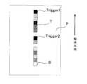
実施例2について、図7のパッチ画像Tについて説明する。図7は、本実施例において分光測色器10が測定を行う、記録材Pの測色用のパッチ画像Tである。図7中には図2(a)と異なり、2つのトリガーパッチ(Trigger1、Trigger2)を形成している。このトリガーパッチは、実施例1で説明した迷光補正と測色タイミングを併せ持つ機能を有する。本実施例では、実施例1と同様に、トリガーパッチには、記録材Pとの色差の最も大きい黒を用いている。なお、記録材Pが長尺の場合は、2つ以上のトリガーパッチを設けてもよいが、本実施例では2つのトリガーパッチを設けた例について、図8を用いて説明を行う。
[Correction of measurement data of spectrocolorimeter]
A patch image T in FIG. 7 will be described with respect to the second embodiment. FIG. 7 shows a color image patch image T of the recording material P that is measured by thespectrocolorimeter 10 in this embodiment. In FIG. 7, unlike FIG. 2A, two trigger patches (Trigger 1 and Trigger 2) are formed. This trigger patch has a function having both the stray light correction and the colorimetric timing described in the first embodiment. In the present embodiment, as in the first embodiment, black having the largest color difference from the recording material P is used for the trigger patch. In the case where the recording material P is long, two or more trigger patches may be provided. In this embodiment, an example in which two trigger patches are provided will be described with reference to FIG.

図8のフローチャートにおいて、図6のフローチャートと同じ処理には同じステップ番号を付し、説明は省略する。なお、本実施例では、トリガーパッチが2つあるため、図8のS109で制御部55が分光測色器10により検出する記録材P上のトリガーパッチは、1つめのトリガーパッチ(Trigger1、TRGパッチ1(黒)と図示)である。S109で制御部55が分光測色器10により測定した結果を、S2_1(λ)とする。  In the flowchart of FIG. 8, the same steps as those in the flowchart of FIG. In this embodiment, since there are two trigger patches, the trigger patch on the recording material P detected by thecontroller 55 by thespectrocolorimeter 10 in S109 of FIG. 8 is the first trigger patch (Trigger 1, TRG). Patch 1 (black). The result measured by thecontrol unit 55 using thespectrocolorimeter 10 in S109 is S2_1 (λ).

S209で制御部55は、同一の記録材P上に形成されたトリガーパッチ2を分光測色器10により検出する。なお、S209で制御部55が分光測色器10により測定した結果を、S2_2(λ)とする。S210で制御部55は、継続搬送される記録材P上に形成されている他のパッチの測定を行う。  In S209, thecontrol unit 55 detects thetrigger patch 2 formed on the same recording material P by thespectrocolorimeter 10. Note that the result of the measurement by thecontrol unit 55 using thespectrocolorimeter 10 in S209 is S2_2 (λ). In S210, thecontrol unit 55 measures other patches formed on the recording material P that is continuously conveyed.

S114で制御部55は、実施例1の式(3)で説明したように、保護ガラス19に付着した紙粉等200に起因する迷光の補正を行う。ここで、制御部55が迷光補正を行う場合、トリガーパッチ1とトリガーパッチ2の差分(S2_2(λ)−S2_1(λ))を用いて補正を行ってもよいし、平均処理((S2_2(λ)+S2_1(λ))/2)を行ってもよい。なお、パッチ画像Tにトリガーパッチが複数含まれる場合、複数のトリガーパッチ(nのトリガーパッチ、nは正の整数)の測定結果の平均処理((S2_1+S2_2+・・・+S2_n)/n)を行っても良い。  In S <b> 114, thecontrol unit 55 corrects stray light caused by the paper dust and the like 200 attached to theprotective glass 19, as described in Expression (3) of the first embodiment. Here, when thecontrol unit 55 performs the stray light correction, thecontrol unit 55 may perform the correction using the difference (S2_2 (λ) −S2_1 (λ)) between thetrigger patch 1 and thetrigger patch 2, or may perform an averaging process ((S2_2 ( λ) + S2_1 (λ)) / 2) may be performed. When the patch image T includes a plurality of trigger patches, the average processing ((S2_1 + S2_2 +... + S2_n) / n) of the measurement results of the plurality of trigger patches (n trigger patches, n is a positive integer) is performed. Also good.

以上が一連の流れである。また、前述の構成及び本シーケンスを分光測色器10に搭載して画像形成装置へ設置し、画像形成装置で出力された本実施例のパッチ画像Tを読み取り、測色演算精度検証を行ったところ、実施例1と同様に高い測色精度を得ることができた。以上、本実施例によれば、測色器の測色精度を向上させることができる。  The above is a series of flows. The above-described configuration and this sequence are mounted on thespectrocolorimeter 10 and installed in the image forming apparatus, and the patch image T of the present embodiment output from the image forming apparatus is read, and the colorimetric calculation accuracy is verified. However, as in Example 1, high colorimetric accuracy could be obtained. As described above, according to the present embodiment, the colorimetric accuracy of the colorimeter can be improved.

実施例1、2では、トリガーパッチと白基準板20を測定し、保護ガラス19か白基準板20のいずれかに汚れが付着しているとして、迷光補正処理を行っている。実施例3では、トリガーパッチに比較して明るいパッチを測定し、白基準板20を測定した結果と明るいパッチを測定した結果とに基づいて、白基準板20に汚れが付着していると判断した場合には、白基準板20の汚れを補正する構成である。  In the first and second embodiments, the trigger patch and thewhite reference plate 20 are measured, and stray light correction processing is performed on the assumption that dirt is attached to either theprotective glass 19 or thewhite reference plate 20. In Example 3, a bright patch is measured as compared to the trigger patch, and it is determined that thewhite reference plate 20 is contaminated based on the result of measuring thewhite reference plate 20 and the result of measuring the bright patch. In such a case, the stain on thewhite reference plate 20 is corrected.

[分光測色器の測定データの補正処理]
本実施例について、図9を用いて説明する。なお、実施例1で説明した処理と同じ処理には同じステップ番号を付し、説明は省略する。図9の処理に使用するパッチ画像Tは、図2(a)又は図7中のBのように配置した、所定の明度のトリガーパッチに比較して明度の高い、即ち明るいパッチを用いている。具体的には、カラー画像形成装置としてイエロー色等の単一色のパッチ(以降、Bパッチと記す)を用いる。なお、記録材P中に、複数のBパッチを設けてもよいが、本実施例では、1つのBパッチを例として図9を用いて説明を行う。
[Correction of measurement data of spectrocolorimeter]
This embodiment will be described with reference to FIG. In addition, the same step number is attached | subjected to the same process as the process demonstrated in Example 1, and description is abbreviate | omitted. The patch image T used for the processing of FIG. 9 uses a patch having a high brightness, that is, a bright patch, which is arranged as shown in B in FIG. 2A or FIG. . Specifically, a single color patch (hereinafter referred to as a B patch) such as yellow is used as the color image forming apparatus. Although a plurality of B patches may be provided in the recording material P, in the present embodiment, description will be given with reference to FIG. 9 using one B patch as an example.

S302で制御部55は、分光測色器10により記録材P上のパッチ画像TのBパッチの測定を行う。なお、図9中では、Bパッチの測定を、S109、S110の処理の後に実行しているが、S110中に行っても良い。S303で制御部55は、S302で測定したBパッチの比較を行う。S302で測定したBパッチの測定結果と、例えば、画像形成装置のパッチの基準値又は初期の測色結果のいずれか(いずれも、Bパッチと同じ色とする)を用いて汚れの比較を行う。ここで、例えば、画像形成装置のパッチの基準値又は初期の測色結果を、イエロー色についてのものとし、この値をY1(λ)とする。なお、Y1(λ)は、予め分光測色器10のメモリ部23に記憶されているものとする。また、測定したBパッチをY2(λ)とする。そして、制御部55は、例えば、S302で行ったBパッチの測定値Y2(λ)と基準値等Y1(λ)との差分値ΔYを算出し、算出した差分値ΔYが所定値よりも大きいか否かを判断する。制御部55は、算出した差分値ΔYが所定値以下である場合、汚れが増したことによる補正処理(以下、汚れ増補正処理という)を行わなくてよい(OKである)と判断する。一方、制御部55は、算出した差分値ΔYが所定値より大きい場合、汚れ増補正処理が必要な状態である(OKではない)と判断する。  In step S <b> 302, thecontrol unit 55 measures the B patch of the patch image T on the recording material P using thespectrocolorimeter 10. In FIG. 9, the measurement of the B patch is performed after the processing of S109 and S110, but may be performed during S110. In step S303, thecontrol unit 55 compares the B patches measured in step S302. Dirt is compared using the measurement result of the B patch measured in S302 and, for example, either the reference value of the patch of the image forming apparatus or the initial color measurement result (both have the same color as the B patch). . Here, for example, the reference value of the patch of the image forming apparatus or the initial color measurement result is for the yellow color, and this value is Y1 (λ). Note that Y1 (λ) is stored in thememory unit 23 of thespectrocolorimeter 10 in advance. The measured B patch is defined as Y2 (λ). Then, for example, thecontrol unit 55 calculates a difference value ΔY between the measured value Y2 (λ) of the B patch performed in S302 and the reference value Y1 (λ), and the calculated difference value ΔY is larger than a predetermined value. Determine whether or not. When the calculated difference value ΔY is equal to or less than the predetermined value, thecontrol unit 55 determines that the correction process (hereinafter referred to as the dirt increase correction process) due to the increase in dirt need not be performed (it is OK). On the other hand, when the calculated difference value ΔY is larger than the predetermined value, thecontrol unit 55 determines that the stain increase correction process is necessary (not OK).

S304で制御部55は、Bパッチとの比較結果から汚れ増補正処理が必要であると判断した場合は、S305で汚れ増補正処理を行う。S305で制御部55は、主に測色演算で用いる白基準プロファイルの最適化を図る。ここで、Bパッチについても式(2)等の関係(例えば、Y1(λ)=c×Y2(λ)+d;c、dは係数)が成り立つ。制御部55は、Bパッチの測定結果から求められる汚れによる測定結果の変動を、白基準の測定値W2(λ)に反映させる。例えば、制御部55は、Bパッチの測定値Y2(λ)とY1(λ)の差分に基づいて、S113で決定した値W2(λ)から汚れによる影響を差し引いた値をW2(λ)として決定する。  In S304, when thecontrol unit 55 determines that the stain increase correction process is necessary from the comparison result with the B patch, thecontrol unit 55 performs the stain increase correction process in S305. In step S305, thecontrol unit 55 optimizes the white reference profile mainly used for the colorimetric calculation. Here, the relationship (2) and the like (for example, Y1 (λ) = c × Y2 (λ) + d; c and d are coefficients) holds for the B patch. Thecontrol unit 55 reflects the variation in the measurement result due to the stain obtained from the measurement result of the B patch in the white reference measurement value W2 (λ). For example, based on the difference between the measured values Y2 (λ) and Y1 (λ) of the B patch, thecontrol unit 55 sets the value obtained by subtracting the influence of dirt from the value W2 (λ) determined in S113 as W2 (λ). decide.

S306で制御部55は、白基準板20の設置初期からの汚れによる光量低下分を抽出しておく。ここで、白基準板20が汚れていない状態では反射率が高く、白基準板20が汚れると反射率が低下する。制御部55は、白基準板20の汚れによる反射率の低下に基づき、光量低下分を抽出している。なお、制御部55は、パッチ画像Tの各階調のパッチの測色データに対して補正処理を行う際に、抽出した光量低下分のデータを用いる。具体的には、紙粉等の汚れは波長毎に分光強度レベルが異なるため、抽出された光量低下分のデータは、測色する各パッチの分光反射率毎に補正係数として演算するために用いられる。  In step S <b> 306, thecontrol unit 55 extracts a light amount decrease due to dirt from the initial installation of thewhite reference plate 20. Here, the reflectance is high when thewhite reference plate 20 is not dirty, and the reflectance decreases when thewhite reference plate 20 is dirty. Thecontrol unit 55 extracts the amount of light reduction based on the decrease in reflectance due to the dirt on thewhite reference plate 20. Note that thecontrol unit 55 uses the extracted light amount reduction data when performing correction processing on the colorimetric data of the patches of each gradation of the patch image T. Specifically, since dirt such as paper dust has a different spectral intensity level for each wavelength, the extracted data for the amount of light reduction is used to calculate as a correction coefficient for each spectral reflectance of each patch to be measured. It is done.

前述の構成及び上述した補正処理を行う分光測色器10を画像形成装置へ設置し、画像形成装置で出力されたパッチ画像Tを読み取り、測色演算精度検証を行った。その結果、保護ガラス19の汚れによる迷光増加、メイン光の減少が生じた場合や白基準板20の汚れの影響がある場合においても、高い測色精度を得ることができた。以上、本実施例によれば、測色器の測色精度を向上させることができる。  Thespectrocolorimeter 10 that performs the above-described configuration and the correction processing described above was installed in the image forming apparatus, the patch image T output from the image forming apparatus was read, and the colorimetric calculation accuracy was verified. As a result, high colorimetric accuracy could be obtained even when stray light increased due to contamination of theprotective glass 19 and main light decreased or when thewhite reference plate 20 was affected by contamination. As described above, according to the present embodiment, the colorimetric accuracy of the colorimeter can be improved.

10 分光測色器
20 白基準板
51 定着部
55 制御部
10spectrocolorimeter 20white reference plate 51 fixingunit 55 control unit

Claims (15)

Translated fromJapanese
複数の階調のパッチからなるパッチ画像を記録材に形成する画像形成手段と、
前記画像形成手段により形成された前記パッチ画像を定着する定着手段と、
前記定着手段により定着された前記パッチ画像に光を照射し、前記パッチ画像からの反射光を測定する測定手段と、
前記測定手段に対向して設置された基準板と、
前記測定手段により前記パッチ画像を測定した結果と、前記基準板を測定した結果とに基づいて、画像の濃度又は色度を制御する制御手段と、
を備える画像形成装置であって、
前記制御手段は、前記測定手段により所定の明度のパッチを測定した結果と、前記基準板を測定した結果とに基づいて、画像の濃度又は色度を制御するための情報を補正することを特徴とする画像形成装置。
Image forming means for forming a patch image made of a plurality of gradation patches on a recording material;
Fixing means for fixing the patch image formed by the image forming means;
Measuring means for irradiating the patch image fixed by the fixing means with light and measuring reflected light from the patch image;
A reference plate installed facing the measuring means;
Control means for controlling the density or chromaticity of the image based on the result of measuring the patch image by the measuring means and the result of measuring the reference plate;
An image forming apparatus comprising:
The control means corrects information for controlling the density or chromaticity of an image based on a result of measuring a patch having a predetermined brightness by the measuring means and a result of measuring the reference plate. An image forming apparatus.
前記画像の濃度又は色度を制御するための情報の補正とは、前記測定手段の迷光の補正であることを特徴とする請求項1に記載の画像形成装置。  The image forming apparatus according to claim 1, wherein the correction of information for controlling the density or chromaticity of the image is correction of stray light of the measurement unit. 前記所定の明度のパッチは、黒色のパッチであることを特徴とする請求項1又は2に記載の画像形成装置。  The image forming apparatus according to claim 1, wherein the patch having the predetermined brightness is a black patch. 前記黒色のパッチは、記録材の搬送方向における前記パッチ画像の先頭に形成されることを特徴とする請求項3に記載の画像形成装置。  The image forming apparatus according to claim 3, wherein the black patch is formed at a head of the patch image in a conveyance direction of the recording material. 前記パッチ画像は、少なくとも一つが記録材の搬送方向における前記パッチ画像の先頭に形成された複数の前記黒色のパッチを有し、
前記制御手段は、前記測定手段による複数の前記黒色のパッチの測定結果に基づいて、前記画像の濃度又は色度を制御するための情報を補正することを特徴とする請求項3に記載の画像形成装置。
The patch image has a plurality of the black patches formed at the head of the patch image in the conveyance direction of the recording material,
The image according to claim 3, wherein the control unit corrects information for controlling density or chromaticity of the image based on measurement results of the plurality of black patches by the measurement unit. Forming equipment.
前記制御手段は、前記測定手段による前記黒のパッチの測定結果に基づいて、前記測定手段による前記基準板の測定結果を補正することを特徴とする請求項3乃至5のいずれか1項に記載の画像形成装置。  The said control means correct | amends the measurement result of the said reference board by the said measurement means based on the measurement result of the said black patch by the said measurement means, The any one of Claim 3 thru | or 5 characterized by the above-mentioned. Image forming apparatus. 前記制御手段は、記録材が前記測定手段に到達する前に前記測定手段による前記基準板の第一の測定を行い、前記記録材が前記測定手段を通過した後に前記測定手段による前記基準板の第二の測定を行うことを特徴とする請求項1乃至6のいずれか1項に記載の画像形成装置。  The control means performs a first measurement of the reference plate by the measuring means before the recording material reaches the measuring means, and after the recording material has passed the measuring means, The image forming apparatus according to claim 1, wherein a second measurement is performed. 前記制御手段は、前記第一の測定の測定結果と前記第二の測定の測定結果とに基づいて、前記基準板の測定結果を算出することを特徴とする請求項7に記載の画像形成装置。  The image forming apparatus according to claim 7, wherein the control unit calculates a measurement result of the reference plate based on a measurement result of the first measurement and a measurement result of the second measurement. . 前記基準板は、白色であることを特徴とする請求項1乃至8のいずれか1項に記載の画像形成装置。  The image forming apparatus according to claim 1, wherein the reference plate is white. 前記パッチ画像は、前記所定の明度のパッチよりも明度の高いパッチを有し、
前記制御手段は、前記測定手段による前記明度の高いパッチの測定結果に基づいて、前記測定手段による前記基準板の測定結果を補正することを特徴とする請求項1乃至9のいずれか1項に記載の画像形成装置。
The patch image has a patch having a higher brightness than the patch of the predetermined brightness,
10. The control unit according to claim 1, wherein the control unit corrects the measurement result of the reference plate by the measurement unit based on the measurement result of the high-brightness patch by the measurement unit. The image forming apparatus described.
前記明度の高いパッチとは、イエロー色のパッチであることを特徴とする請求項10に記載の画像形成装置。  The image forming apparatus according to claim 10, wherein the high-brightness patch is a yellow patch. 前記測定手段は、白色の光源を有することを特徴とする請求項1乃至11のいずれか1項に記載の画像形成装置。  The image forming apparatus according to claim 1, wherein the measurement unit includes a white light source. 前記白色の光源は、400nm〜700nmの波長域の光を照射することを特徴とする請求項12に記載の画像形成装置。  The image forming apparatus according to claim 12, wherein the white light source emits light in a wavelength range of 400 nm to 700 nm. 前記測定手段は、前記パッチ画像からの反射光を分光する分光手段と、前記分光手段により分光された光が入射されるラインセンサと、を有することを特徴とする請求項1乃至13のいずれか1項に記載の画像形成装置。  14. The measurement unit according to claim 1, further comprising: a spectroscopic unit that splits the reflected light from the patch image; and a line sensor that receives the light split by the spectroscopic unit. 2. The image forming apparatus according to item 1. 前記ラインセンサの画素は、前記分光された光の波長と対応付けられていることを特徴とする請求項14に記載の画像形成装置。  The image forming apparatus according to claim 14, wherein a pixel of the line sensor is associated with a wavelength of the dispersed light.
JP2013129813A2013-06-202013-06-20Image forming apparatusPendingJP2015004811A (en)

Priority Applications (2)

Application NumberPriority DateFiling DateTitle
JP2013129813AJP2015004811A (en)2013-06-202013-06-20Image forming apparatus
US14/300,134US9164456B2 (en)2013-06-202014-06-09Image forming apparatus

Applications Claiming Priority (1)

Application NumberPriority DateFiling DateTitle
JP2013129813AJP2015004811A (en)2013-06-202013-06-20Image forming apparatus

Publications (1)

Publication NumberPublication Date
JP2015004811Atrue JP2015004811A (en)2015-01-08

Family

ID=52111023

Family Applications (1)

Application NumberTitlePriority DateFiling Date
JP2013129813APendingJP2015004811A (en)2013-06-202013-06-20Image forming apparatus

Country Status (2)

CountryLink
US (1)US9164456B2 (en)
JP (1)JP2015004811A (en)

Cited By (7)

* Cited by examiner, † Cited by third party
Publication numberPriority datePublication dateAssigneeTitle
JP2017067883A (en)*2015-09-292017-04-06コニカミノルタ株式会社Image forming system and image forming apparatus
JP2018059913A (en)*2016-10-032018-04-12ゼロックス コーポレイションXerox CorporationHyperspectral Imaging System
JP2019049445A (en)*2017-09-082019-03-28キヤノン株式会社Detection device and image forming apparatus
US10671005B2 (en)2017-09-082020-06-02Canon Kabushiki KaishaDetecting apparatus and image forming apparatus
US10728399B2 (en)2017-12-082020-07-28Canon Kabushiki KaishaSpectral colorimetry apparatus and image forming apparatus to control the number of detection times
JP2020527712A (en)*2017-07-192020-09-10シーメンス・ヘルスケア・ダイアグノスティックス・インコーポレーテッドSiemens Healthcare Diagnostics Inc. Stray light compensation methods and equipment for evaluating the characteristics of specimens
JP7630923B2 (en)2020-05-182025-02-18キヤノン株式会社 Colorimeter

Families Citing this family (2)

* Cited by examiner, † Cited by third party
Publication numberPriority datePublication dateAssigneeTitle
JP6724344B2 (en)*2015-11-172020-07-15富士ゼロックス株式会社 Image forming device
WO2018021266A1 (en)*2016-07-292018-02-01キヤノン株式会社Image forming apparatus

Family Cites Families (6)

* Cited by examiner, † Cited by third party
Publication numberPriority datePublication dateAssigneeTitle
US5925889A (en)1997-10-211999-07-20Hewlett-Packard CompanyPrinter and method with media gloss and color determination
JP4065485B2 (en)*2001-11-092008-03-26キヤノン株式会社 Method for correcting output value of color detection means of color image forming apparatus, and color image forming apparatus provided with the method
US6975775B2 (en)*2002-03-062005-12-13Radiant Imaging, Inc.Stray light correction method for imaging light and color measurement system
JP2004085376A (en)2002-08-272004-03-18Fuji Photo Film Co LtdDensitometric device and image recording device
JP2006214968A (en)2005-02-072006-08-17Dainichiseika Color & Chem Mfg Co Ltd Method for detecting wavelength shift, method for correcting spectroscopic measurement data, and recording medium
US8490968B2 (en)*2006-07-272013-07-23Canon Kabushiki KaishaImage forming apparatus with conveyance interval adjustment for recording paper

Cited By (11)

* Cited by examiner, † Cited by third party
Publication numberPriority datePublication dateAssigneeTitle
JP2017067883A (en)*2015-09-292017-04-06コニカミノルタ株式会社Image forming system and image forming apparatus
US9811040B2 (en)2015-09-292017-11-07Konica Minolta, Inc.Image forming system performing predetermined processing within a certain amount of time after preparation operation, image forming apparatus, and storage medium
JP2018059913A (en)*2016-10-032018-04-12ゼロックス コーポレイションXerox CorporationHyperspectral Imaging System
JP2020527712A (en)*2017-07-192020-09-10シーメンス・ヘルスケア・ダイアグノスティックス・インコーポレーテッドSiemens Healthcare Diagnostics Inc. Stray light compensation methods and equipment for evaluating the characteristics of specimens
JP7048718B2 (en)2017-07-192022-04-05シーメンス・ヘルスケア・ダイアグノスティックス・インコーポレーテッド Stray light compensation method and equipment for evaluating sample characteristics
US11815519B2 (en)2017-07-192023-11-14Siemens Healthcare Diagnostics Inc.Stray light compensating methods and apparatus for characterizing a specimen
JP2019049445A (en)*2017-09-082019-03-28キヤノン株式会社Detection device and image forming apparatus
US10671005B2 (en)2017-09-082020-06-02Canon Kabushiki KaishaDetecting apparatus and image forming apparatus
US10877417B2 (en)2017-09-082020-12-29Canon Kabushiki KaishaDetecting apparatus and image forming apparatus
US10728399B2 (en)2017-12-082020-07-28Canon Kabushiki KaishaSpectral colorimetry apparatus and image forming apparatus to control the number of detection times
JP7630923B2 (en)2020-05-182025-02-18キヤノン株式会社 Colorimeter

Also Published As

Publication numberPublication date
US20140376932A1 (en)2014-12-25
US9164456B2 (en)2015-10-20

Similar Documents

PublicationPublication DateTitle
US9164456B2 (en)Image forming apparatus
JP2013007610A (en)Color measuring unit and image forming apparatus
US10837835B2 (en)Colorimetry apparatus and image forming apparatus
US8873045B2 (en)Spectrocolorimeter and image forming apparatus
US10129441B2 (en)Image forming apparatus for forming test pattern on sheet using coloring material of plurality of colors
US9513170B2 (en)Spectral color sensor and image forming apparatus
JP6021352B2 (en) Color image forming apparatus and correction method
JP2011186087A (en)Color image forming apparatus
US20150350460A1 (en)Image forming apparatus
CN102413254B (en)The image adjusting method of image reading apparatus, image forming apparatus and image reading apparatus
JP6357906B2 (en) Image reading apparatus and image forming apparatus
US10078012B2 (en)Measurement apparatus with adjustment for spectral shift
US8948634B2 (en)Image forming apparatus
JP2007059975A (en)Image processing system, image processing method and program
JP2015148456A (en) Colorimeter, image forming device
JP6468752B2 (en) Color measuring device, image forming apparatus, and color measuring method
US11787197B2 (en)Image forming apparatus and measurement apparatus
JP6252162B2 (en) Image reading apparatus, image forming apparatus, and program
JP3711644B2 (en) Image forming apparatus
JP6763214B2 (en) Image reader, image forming device, and control program for image reader
US9002216B2 (en)Image forming apparatus that forms a test pattern and carries out correction
JPH0619319A (en) Image forming device
JP2013231782A (en)Image forming apparatus

Legal Events

DateCodeTitleDescription
RD03Notification of appointment of power of attorney

Free format text:JAPANESE INTERMEDIATE CODE: A7423

Effective date:20160215

RD04Notification of resignation of power of attorney

Free format text:JAPANESE INTERMEDIATE CODE: A7424

Effective date:20160215


[8]ページ先頭

©2009-2025 Movatter.jp