JP2015003013A - Electrosurgical instrument with light guide - Google Patents
Electrosurgical instrument with light guideDownload PDFInfo
- Publication number
- JP2015003013A JP2015003013AJP2014123307AJP2014123307AJP2015003013AJP 2015003013 AJP2015003013 AJP 2015003013AJP 2014123307 AJP2014123307 AJP 2014123307AJP 2014123307 AJP2014123307 AJP 2014123307AJP 2015003013 AJP2015003013 AJP 2015003013A
- Authority
- JP
- Japan
- Prior art keywords
- light
- electrode
- light guide
- instrument
- entrance window
- Prior art date
- Legal status (The legal status is an assumption and is not a legal conclusion. Google has not performed a legal analysis and makes no representation as to the accuracy of the status listed.)
- Granted
Links
Images


Classifications
- A—HUMAN NECESSITIES
- A61—MEDICAL OR VETERINARY SCIENCE; HYGIENE
- A61B—DIAGNOSIS; SURGERY; IDENTIFICATION
- A61B18/00—Surgical instruments, devices or methods for transferring non-mechanical forms of energy to or from the body
- A61B18/04—Surgical instruments, devices or methods for transferring non-mechanical forms of energy to or from the body by heating
- A61B18/12—Surgical instruments, devices or methods for transferring non-mechanical forms of energy to or from the body by heating by passing a current through the tissue to be heated, e.g. high-frequency current
- A—HUMAN NECESSITIES
- A61—MEDICAL OR VETERINARY SCIENCE; HYGIENE
- A61B—DIAGNOSIS; SURGERY; IDENTIFICATION
- A61B5/00—Measuring for diagnostic purposes; Identification of persons
- A61B5/0059—Measuring for diagnostic purposes; Identification of persons using light, e.g. diagnosis by transillumination, diascopy, fluorescence
- A61B5/0082—Measuring for diagnostic purposes; Identification of persons using light, e.g. diagnosis by transillumination, diascopy, fluorescence adapted for particular medical purposes
- A61B5/0084—Measuring for diagnostic purposes; Identification of persons using light, e.g. diagnosis by transillumination, diascopy, fluorescence adapted for particular medical purposes for introduction into the body, e.g. by catheters
- A—HUMAN NECESSITIES
- A61—MEDICAL OR VETERINARY SCIENCE; HYGIENE
- A61B—DIAGNOSIS; SURGERY; IDENTIFICATION
- A61B18/00—Surgical instruments, devices or methods for transferring non-mechanical forms of energy to or from the body
- A61B18/18—Surgical instruments, devices or methods for transferring non-mechanical forms of energy to or from the body by applying electromagnetic radiation, e.g. microwaves
- A—HUMAN NECESSITIES
- A61—MEDICAL OR VETERINARY SCIENCE; HYGIENE
- A61B—DIAGNOSIS; SURGERY; IDENTIFICATION
- A61B5/00—Measuring for diagnostic purposes; Identification of persons
- A61B5/0059—Measuring for diagnostic purposes; Identification of persons using light, e.g. diagnosis by transillumination, diascopy, fluorescence
- A61B5/0075—Measuring for diagnostic purposes; Identification of persons using light, e.g. diagnosis by transillumination, diascopy, fluorescence by spectroscopy, i.e. measuring spectra, e.g. Raman spectroscopy, infrared absorption spectroscopy
- A—HUMAN NECESSITIES
- A61—MEDICAL OR VETERINARY SCIENCE; HYGIENE
- A61B—DIAGNOSIS; SURGERY; IDENTIFICATION
- A61B18/00—Surgical instruments, devices or methods for transferring non-mechanical forms of energy to or from the body
- A61B18/04—Surgical instruments, devices or methods for transferring non-mechanical forms of energy to or from the body by heating
- A61B18/12—Surgical instruments, devices or methods for transferring non-mechanical forms of energy to or from the body by heating by passing a current through the tissue to be heated, e.g. high-frequency current
- A61B18/14—Probes or electrodes therefor
- A61B18/1477—Needle-like probes
- A—HUMAN NECESSITIES
- A61—MEDICAL OR VETERINARY SCIENCE; HYGIENE
- A61B—DIAGNOSIS; SURGERY; IDENTIFICATION
- A61B18/00—Surgical instruments, devices or methods for transferring non-mechanical forms of energy to or from the body
- A61B2018/00571—Surgical instruments, devices or methods for transferring non-mechanical forms of energy to or from the body for achieving a particular surgical effect
- A61B2018/00607—Coagulation and cutting with the same instrument
- A—HUMAN NECESSITIES
- A61—MEDICAL OR VETERINARY SCIENCE; HYGIENE
- A61B—DIAGNOSIS; SURGERY; IDENTIFICATION
- A61B18/00—Surgical instruments, devices or methods for transferring non-mechanical forms of energy to or from the body
- A61B2018/00636—Sensing and controlling the application of energy
- A61B2018/00904—Automatic detection of target tissue
- A—HUMAN NECESSITIES
- A61—MEDICAL OR VETERINARY SCIENCE; HYGIENE
- A61B—DIAGNOSIS; SURGERY; IDENTIFICATION
- A61B18/00—Surgical instruments, devices or methods for transferring non-mechanical forms of energy to or from the body
- A61B2018/00982—Surgical instruments, devices or methods for transferring non-mechanical forms of energy to or from the body combined with or comprising means for visual or photographic inspections inside the body, e.g. endoscopes
- A—HUMAN NECESSITIES
- A61—MEDICAL OR VETERINARY SCIENCE; HYGIENE
- A61B—DIAGNOSIS; SURGERY; IDENTIFICATION
- A61B18/00—Surgical instruments, devices or methods for transferring non-mechanical forms of energy to or from the body
- A61B18/04—Surgical instruments, devices or methods for transferring non-mechanical forms of energy to or from the body by heating
- A61B18/12—Surgical instruments, devices or methods for transferring non-mechanical forms of energy to or from the body by heating by passing a current through the tissue to be heated, e.g. high-frequency current
- A61B18/14—Probes or electrodes therefor
- A61B2018/1405—Electrodes having a specific shape
- A61B2018/1435—Spiral
- A—HUMAN NECESSITIES
- A61—MEDICAL OR VETERINARY SCIENCE; HYGIENE
- A61B—DIAGNOSIS; SURGERY; IDENTIFICATION
- A61B2218/00—Details of surgical instruments, devices or methods for transferring non-mechanical forms of energy to or from the body
- A61B2218/001—Details of surgical instruments, devices or methods for transferring non-mechanical forms of energy to or from the body having means for irrigation and/or aspiration of substances to and/or from the surgical site
- A61B2218/002—Irrigation
Landscapes
- Health & Medical Sciences (AREA)
- Life Sciences & Earth Sciences (AREA)
- Physics & Mathematics (AREA)
- Surgery (AREA)
- Engineering & Computer Science (AREA)
- Veterinary Medicine (AREA)
- Animal Behavior & Ethology (AREA)
- Biomedical Technology (AREA)
- Heart & Thoracic Surgery (AREA)
- Medical Informatics (AREA)
- Molecular Biology (AREA)
- Public Health (AREA)
- General Health & Medical Sciences (AREA)
- Pathology (AREA)
- Biophysics (AREA)
- Spectroscopy & Molecular Physics (AREA)
- Nuclear Medicine, Radiotherapy & Molecular Imaging (AREA)
- Otolaryngology (AREA)
- Plasma & Fusion (AREA)
- Electromagnetism (AREA)
- Surgical Instruments (AREA)
Abstract
Description
Translated fromJapanese本発明は、電気外科的に生物組織に衝撃を与える器具に関し、具体的には高周波(HF)手術用の器具に関する。 The present invention relates to an instrument that electrosurgically impacts biological tissue, and more particularly to an instrument for high frequency (HF) surgery.
火花放電を生成して生物組織に衝撃を与え、それによって生成する光を分析デバイスに供給する電気外科用器具が知られている。 Electrosurgical instruments are known that generate a spark discharge to impact biological tissue and thereby provide the generated light to an analytical device.
この目的で、特許文献1は、医薬用途のマイクロプラズマヘッドを開示している。このマイクロプラズマヘッドは、細長い可撓性の器具により形成され、器具の端部にはプラズマを生成する電極が設けられている。ライトガイドは、その開口前側表面が光入口窓を形成しており、末端はわずかにへこむようになっている。プラズマは光入口窓の前部で生成し、その光は光入口窓に吸収される。接続された光分析デバイスは、プラズマが発する光のスペクトル、具体的には特徴的な燐光線を調べる。このことは、血管内プラークを除去する器具の使用に応じるプラーク生体組織の区別に役立つ。 For this purpose, Patent Document 1 discloses a microplasma head for pharmaceutical use. The microplasma head is formed of an elongated flexible instrument, and an electrode for generating plasma is provided at the end of the instrument. The front surface of the light guide forms a light entrance window, and the end of the light guide is slightly recessed. The plasma is generated at the front of the light entrance window and the light is absorbed by the light entrance window. The connected optical analysis device examines the spectrum of light emitted by the plasma, specifically the characteristic phosphorescence. This helps to differentiate plaque anatomy in response to the use of an instrument to remove intravascular plaque.
さらに繊細な光検査が、特許文献2により提案されている。そこで例示されている細長い器具は、陶製の末端部品が球状にへこんだ光ファイバを中心部に包含する。このへこみ内でプラズマを生成する2つの鋭利端をもつ電極も、このへこみ内に配置されている。 Further, a delicate optical inspection is proposed in Patent Document 2. The elongate instrument illustrated therein includes in the center an optical fiber with a spherically recessed ceramic end piece. An electrode with two sharp edges that generates a plasma within the recess is also disposed within the recess.
スペクトル光分析がうまく行くためは、光がスペクトル分析器に達することを要する。 In order for spectral light analysis to work, light needs to reach the spectrum analyzer.
それを確実にすることが、本発明の課題である。 Ensuring that is the subject of the present invention.
この課題は、請求項1による器具により解決される。 This problem is solved by a device according to claim 1.
本発明による器具は、ラインを介して電源に接続され得るかまたは接続されている、少なくとも1つの電極を包含する。電源は、例えば高周波ジェネレータであり得る。電極は、モノポーラであり得、1または複数の部品でなり得る。この場合、電気回路を閉じるのに必要な対電極が、中性極として患者に固定されている。 The device according to the invention comprises at least one electrode which can or is connected to a power supply via a line. The power source can be, for example, a high frequency generator. The electrode can be monopolar and can be composed of one or more parts. In this case, the counter electrode necessary to close the electrical circuit is fixed to the patient as a neutral electrode.
器具は、直視下手術に用いられる器具として、または腹腔鏡的使用に提供される器具として具現化され得る。器具は、特に高周波手術手順用にセットアップされ、その場合、有利にも200nmから1200nmのスペクトルの放電が電極で生じる。好ましくは、そのようなケースでは電源として高周波ジェネレータが備えられる。 The instrument can be embodied as an instrument used in direct-view surgery or as an instrument provided for laparoscopic use. The instrument is set up especially for high frequency surgical procedures, in which case a discharge with a spectrum of 200 nm to 1200 nm is advantageously generated at the electrodes. Preferably, in such a case, a high frequency generator is provided as a power source.
本発明による器具は、光分析デバイスと接続され、光分析デバイスにより、放電により捕捉された生物組織に関する情報が吸収光の特徴から得られる。この光を吸収するために、流体塊により形成される光入口窓が設けられる。 The instrument according to the invention is connected to an optical analysis device, whereby information about the biological tissue captured by the discharge is obtained from the characteristics of the absorbed light. In order to absorb this light, a light entrance window formed by the fluid mass is provided.
後者はライトガイドと接触して吸収光をライトガイドに転送し、後者を介して光分析デバイスに転送する。流体塊は、たとえ火花放電に近接しても煙粒子の堆積により汚れるあるいは炭化することのない液体面を有する。したがって、火花放電から発せられる光をスペクトルの変形なしに吸収することが可能である。 The latter contacts the light guide and transfers the absorbed light to the light guide and through the latter to the light analysis device. The fluid mass has a liquid surface that does not become fouled or charred by the accumulation of smoke particles even in the vicinity of the spark discharge. Therefore, it is possible to absorb the light emitted from the spark discharge without distortion of the spectrum.
特に光入口窓が電極のすぐ近くに配置される場合、火花放電から発せられる光は実際確実に吸収され得、火花と光入口窓の間にある組織部分によって煙などに覆われることがない。好ましいケースでは、光入口窓は、電極に接するように配置され得、例えば流体塊は電極とライトガイドの間で粘着により保持される。この目的では、光入口窓および/または電極が親水性表面を包含すれば有利である。実質的に静止している流体塊はこのようにしてライトガイドと電極の表面間に保持され得る。好ましいケースでは、互いに対向して位置しその間には電位差のない2つの親水性の電極表面が間隙を形成し、その底部は親水性ライトガイド表面により形成されている。間隙の幅は、好ましくは、流体塊が毛細管効果により間隙内に保持されるほど小さい。流体塊を形成する流体は、付近に存在するリンス流体、リンパ液であり得、またはチャネルを通して供給される流体でもあり得る。チャネルは、例えばライトガイドを通って延び得る。 Especially when the light entrance window is placed in the immediate vicinity of the electrodes, the light emitted from the spark discharge can indeed be absorbed reliably and is not covered by smoke or the like by the tissue part between the spark and the light entrance window. In a preferred case, the light entrance window can be placed in contact with the electrode, for example a fluid mass is retained by adhesion between the electrode and the light guide. For this purpose, it is advantageous if the light entrance window and / or the electrode include a hydrophilic surface. A substantially stationary fluid mass can thus be held between the surface of the light guide and the electrode. In a preferred case, two hydrophilic electrode surfaces positioned opposite each other and having no potential difference form a gap, and the bottom is formed by a hydrophilic light guide surface. The width of the gap is preferably so small that the fluid mass is retained in the gap by the capillary effect. The fluid forming the fluid mass can be a nearby rinsing fluid, lymph fluid, or can be a fluid supplied through the channel. The channel may extend through the light guide, for example.
光入口窓はまた、流れる流体塊により形成されてもよく、例えば透明の液体が電極から噴出する。例えば、ライトガイドは、流体を流体出口開口部に導き、次いでそこから流体噴流が流出する、流体チャネル内に配置され得る。それらは光入口窓を形成し、火花放電から生じる光を流体チャネル内に案内し、そこで光はライトガイドにさらに吸収される。 The light entrance window may also be formed by a flowing fluid mass, for example, a transparent liquid is ejected from the electrode. For example, the light guide can be placed in a fluid channel that directs fluid to a fluid outlet opening from which a fluid jet flows. They form a light entrance window and guide the light resulting from the spark discharge into the fluid channel where it is further absorbed by the light guide.
光入口窓を形成する流体塊が静止するまたは流れるようにされようが、互いに電気的に接続され、間に光入口窓が配置された少なくとも2つの領域を電極が包含する場合は有利である。したがって、流体塊は、同じ電位をもつ電極表面の間の、生成される放電の最も近傍に配置され得る。 Whether the fluid mass forming the light entrance window is stationary or flowing, it is advantageous if the electrode comprises at least two regions which are electrically connected to each other and between which the light entrance window is arranged. Thus, the fluid mass can be placed closest to the generated discharge between the electrode surfaces with the same potential.
特に好ましい実施形態の場合、器具は、電極を支持する剛性区域を備えるライトガイドを包含する。剛性区域は、例えば、1または複数のワイヤ、金属ストリップなどからなる電極が配置されている先細先端と融合し得る。先細先端の角度は、例えば、5°から90°の間であり得る。次に、角度のサイズは、例えば1.46のガラスの使用に応じて、使用されるライトガイドの屈折率の関数として、および空気(1.0)または水(1.33)などのライトガイドの周りの媒体の屈折率の関数として、決定される。 In a particularly preferred embodiment, the instrument includes a light guide with a rigid area that supports the electrodes. The rigid area may be fused with a tapered tip on which an electrode made of, for example, one or more wires, metal strips, etc. is disposed. The angle of the tapered tip can be, for example, between 5 ° and 90 °. Next, the angle size is a function of the refractive index of the light guide used, eg, depending on the use of 1.46 glass, and a light guide such as air (1.0) or water (1.33). Is determined as a function of the refractive index of the medium around.
好ましくは、電極は、複数の巻回で先細先端を覆うワイヤにより形成される。流体塊は、粘着力と、該当する場合は毛細作用により、隣接する巻回の間の間隙内に留まり得る。前記流体塊は、光入口窓を形成し、光をライトガイドに転送する。放電が生じる円錐形状のワイヤ巻回の位置にかかわらず、生じた光の大部分はライトガイドに吸収され、かくしてそのまま光分析デバイスに供給され得る。例えば、ライトガイドは、例えばガラス、プラスチックなどの導光材料により具現化され得る。ライトガイドは、内部を金属被覆されているか、代わりに定常のまたは流れる流体で満たされていてもよい、適切な管またはカニューレからもなり得る。本発明の有利な実施のさらなる詳細は、図面、明細書、または特許請求の範囲の主題である。 Preferably, the electrode is formed of a wire that covers the tapered tip with a plurality of turns. The fluid mass can remain in the gap between adjacent turns due to adhesion and, if applicable, capillary action. The fluid mass forms a light entrance window and transfers light to the light guide. Regardless of the position of the conical wire winding where the discharge occurs, most of the generated light is absorbed by the light guide and can thus be supplied directly to the optical analysis device. For example, the light guide may be embodied by a light guide material such as glass or plastic. The light guide can also consist of a suitable tube or cannula that is metallized inside or alternatively filled with a steady or flowing fluid. Further details of advantageous implementations of the invention are the subject matter of the drawings, the description or the claims.
図1は、ユーザーにより案内される器具11、給電デバイス12および光分析デバイス13を含む電気手術用デバイス10を例示する。電気手術用デバイス10は、例示のように別ユニットとして、またはデバイス12の一部としても、具現化され得る。器具11をデバイス12と光分析デバイス13に接続するため、少なくとも1つの電線15、ライトガイド16および所望により少なくとも1つの流体ライン17を含む対応するライン14が設けられる。電線15は、器具11の電極18を、例えば高周波ジェネレータを含む給電デバイス12に接続する。ライトガイド16は、電極18に設けられた光入口窓19を光分析デバイス13に接続する。 FIG. 1 illustrates an
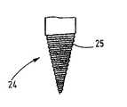
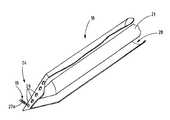
器具11は、腹腔鏡として、または図1に象徴的に例示されるように直視下外科的手順用の器具としても、具現化され得る。器具11は、図2に別途例示される電極支持体20を包含する。前記電極支持体は、例えば、ライン14のライトガイド16に接続される剛性ライトガイド21により形成される。接続は、1または複数の操作素子23も支持し得るハンドル22内でなされ得るか、または、前記ハンドルから隔たるようになされ得る。図3に例示されるように、剛性ライトガイド21により形成される電極支持体は、一方の端部24で円錐形状に先細になるように具現化され得る。この端部24において、一条または多条スパイラル溝25が具現化され得、そのリードは、スパイラル溝25に収容されるワイヤの幅よりも大きい。図4は、電極18を形成し、らせん状に巻かれるようにスパイラル溝25内に挿入されるワイヤ26を例示する。このワイヤ26が実際の電極を形成する。これは、剛性ライトガイド21に沿って延びる1または複数のワイヤを介して電線15に接続される。 The
この関係は、図5に再び別途例示される。ワイヤ26の隣接する巻回26a、26bの間にはある距離が存在するので、ライトガイド21またはその端部24がそれぞれその場所でなおも視認できる。好ましくは、ライトガイド表面は親水的に具現化される。さらに、このワイヤ26の表面は、好ましくは、少なくともライトガイド21に隣接する場所は親水的に具現化される。このことは、ライトガイド21がワイヤ26の巻回の間で露出される部分と、ワイヤ26の隣接部分が、わずかに水に濡れ、粘着により水塊を保持することを意味する。 This relationship is illustrated separately again in FIG. Since there is a distance between the
図5には、流体塊27が粘着によりワイヤ26の隣接する巻回の間に保持されることが例示されている。巻回26a、26bの間の間隙が十分に狭い場合は、毛細作用が存在するともいえる。ワイヤ26の円形断面により、間隙はライトガイド方向に広がりもする。 FIG. 5 illustrates that the
流体塊27が接触する表面の親水的な特徴は、その表面の外向きの凹曲線により見られ得る。流体塊27は、実質的には水、例えばリンス液、リンパ液などからなる。前記流体塊は、光入口窓19を形成し、それを通じてワイヤ26から発せられた火花放電の光が吸収されてライトガイド21に転送される。 The hydrophilic character of the surface with which the
このケースは、環境から流れる、液体により形成された静止状態の流体塊27に関する。煙または他の固形物粒子は、その液体面に恒久的に留まることができない。したがって、操作中、火花放電から発せられた光はそのまま確実に光分析デバイス13に達する。それによる「光」は、可視光のみならず、所望の場合は赤外光および/または紫外光も意味する。 This case relates to a
これに関し記載した電気手術用デバイス10は、以下のように作動する。 The
ユーザーは、電気外科的手順、好ましくは高周波電気外科的手順を実行するのに器具11を用いる。詳細には例示されていない、デバイス12に接続される中性極を患者に固定する。次にユーザーは電極18により患者組織に対して放電でき、それによって例えば切開、凝固などの作用を及ぼすことができる。火花放電により生成される光は治療対象組織により微妙に影響される。放電により治療される組織の部分、分子、分子断片、原子、イオンが火花内に達して発光が生じる。この光は光入口窓19を通じて吸収され、ライトガイド21、16を介して光分析デバイス13に供給される。前記光分析デバイス13は光のスペクトル分解を実行し、治療対象組織の種類をできるだけ精密に決定するために吸収光のスペクトルを分析する。術者が見たり聞いたり感じることのできる対応する信号は、次に、組織の種類または組織の種類の変化を表示し得る。 The user uses the
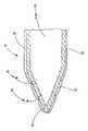
数々の変更が可能であることが指摘される。例えば、光分析デバイス13は、器具11の一部であり得る。例えば、光分析デバイス13は、器具11のハンドル22に取り付けられ得る。電極18、電極支持体20および流体塊27にはさらなる変更が関係し得る。この目的で、図6は電極支持体20を例示する。後者は好ましくは導光材料で作製される。こうして剛性ライトガイド21を形成する。剛性ライトガイド21には、適切な流体、例えば生理食塩水溶液が端部24へとその中を通って案内される流体チャネル28が設けられる。その場所に、流体チャネル28に接続される1または好ましくは複数の流体出口開口部29が設けられる。流体出口開口部29は、好ましくは、ワイヤ26の互いに離れている巻回26a、26bの間を空にするように、すなわち、図7に示されるようにスパイラル溝25の間に位置するように、配置される。 It is pointed out that numerous changes are possible. For example, the
そのような器具の場合、流体塊27は操作中は流体出口開口部29を介して常に再生され得る。また、次に光入口窓19として作用する流体噴流が流体出口開口部29から流出する流体圧の機能ももたらされ得る。流体出口開口部29は次いでワイヤ26で生じる放電に直接接続されてその光を吸収する。この実施形態の場合、光学的に不透明な材料を剛性ライトガイド21の代わりに使用し、ライトガイドを流体チャネル28内に配置して、その場所で流体からの光を吸収するようにすることも可能である。 In such an instrument, the
図1から図7による上述の実施形態すべての場合において、剛性ライトガイド21は可撓性のライトガイドとしても具現化され得ることが指摘される。このことは、腹腔鏡的に使用される器具11に関して特に適用する。 In all the above embodiments according to FIGS. 1 to 7 it is pointed out that the rigid
本発明による器具11のさらなる実施形態を図8以下に示す。小型の薄壁管として、電極18は、流体出口開口部29が具現化される端部24のところで導電性となるように、または部分的に適用される導電金属層により具現化される。水をベースとする例えば生理食塩水溶液または別の流体などの流体が、流体チャネル28を通って流体出口開口部29へと案内される。その場所で流出する流体噴流27aが、光入口窓19を形成する。流体チャネル28内の流体は、ライトガイド21を形成できる。流体圧が少なく、流体出口開口部29から流体が滴るかまたは染み出すだけの場合は、液体が満たされた流体出口開口部29が光入口窓19を形成する。 A further embodiment of the
好ましくは端部24まで延びるライトガイド21は、チャネル28内に配置されている。チャネル28は、流体出口開口部29を介してチャネル28内に達する光を捕捉するための光コレクタとして作用し、光を光分析デバイス13に供給する。 A
例示するように、電極18の端部24並びにライトガイド21の端部は、円錐形状に、または、必要に応じて、例えばボール状、へら状などの他の形状に形成され得る。 As illustrated, the
放電が光入口窓19の領域で生じると、発光の検出が改良され得る。この目的で、図8による例示的実施形態は、図8bに例示されるように、電気絶縁層32を包含し得る。この電気絶縁層32、例えばプラスチック層を、光入口窓19を形成する開口部を備える電極18に適用すると、電気絶縁層32は異なる厚みを有する。光入口窓の開口部の端の領域では、厚みが薄い絶縁層が生成される。薄い層で覆われたこれらの場所は、1000から10000ボルトの範囲の高周波電圧を印加すると好ましくは貫通され、それによって組織と電極の間の放電が光入口窓19で直接生じる。したがって、放電起点、かくして光入口窓19の領域のちょうど端のところの発光の起点を特定することが可能である。ライトガイド29への通路は可能な限り狭い。こうして、事実上いっさいの損失なしに発光の決定を行うことができる。If a discharge occurs in the region of the
図9は、さらなる変更形態を示す。電極18は、電源に接続された導電性の小型の平らなプレート30を包含する。例えばプラスチック製の、光分析デバイス13に接続されたライトガイド21a、21bが、小型プレート30の少なくとも片方の、好ましくは両方の平面上に配置される。ライトガイドは、小型プレート30の上に立つ、ライトガイド21a、21bの狭い側31に見えている。小型プレート30の平らな側と同様に、狭い側31は、好ましくは、親水性となるように具現化され、その結果としてライトガイド21a、21bと小型プレート30に粘着により保持され、光入口窓19を形成する流体塊27が、操作中にリンパ液、リンス液などから形成される。特に流体塊27を生成するように、または流体塊27を連続的に補充し、再生するように、流体供給体も設けられ得る。 FIG. 9 shows a further modification.
電気外科的に生物組織に衝撃を与えるための本発明による器具11は、電極18と、流体塊27により形成された光入口窓19に接続されたライトガイド21とを備える。ライトガイドは、光分析デバイス13に接続されて、高周波手術に応じて電極18で生成された光を吸収するようになっており、その光を光分析デバイス13に供給するようになっている。光入口窓19は、光の起点、すなわちまさに電極に、つまり火花放電が生じるところに配置される。煙または光入口窓19上の粒子の堆積による吸収光の不純化は、事実状回避され得る。 The
10 電気手術用デバイス
11 器具
12 デバイス
13 光分析デバイス
14 ライン
15 電線
16 ライトガイド
17 流体ライン
18 電極
19 光入口窓
20 電極支持体
21 剛性ライトガイド
22 ハンドル
23 操作素子
24 ライトガイド21の端部
25 スパイラル溝
26 ワイヤ
26a 電極18の領域を形成するワイヤ巻回
26b 電極18の領域を形成するワイヤ巻回
27 流体塊
27a 流体噴出として流出する流体塊、
28 流体チャネル
29 流体出口開口部
30 小型プレート
31 狭い側
32 電気絶縁層
DESCRIPTION OF
28
Claims (15)
Translated fromJapanese電線(15)を介して電源(12)に接続され得る電極(18)と、
少なくとも1つの光入口窓(19)を始点として延び、それを通じて前記器具が光分析デバイス(13)に接続され得るライトガイド(21)とを備え、
前記光入口窓(19)は流体塊(27)により形成されている、器具。An instrument for electrosurgical impact on biological tissue, specifically a high frequency surgical instrument,
An electrode (18) that can be connected to a power source (12) via a wire (15);
A light guide (21) extending from at least one light entrance window (19) through which the instrument can be connected to a light analysis device (13);
The instrument, wherein the light entrance window (19) is formed by a fluid mass (27).
電線(15)を介して電源(12)に接続され得る電極(18)と、
少なくとも1つの光入口窓(19)を始点として延び、それを通じて前記器具(11)が光分析デバイス(13)に接続され得るライトガイド(21)とを備え、
前記ライトガイド(21)は、前記電極(18)を支持する端部(24)を包含する、器具。An instrument (11) for electrosurgical impact on biological tissue, specifically for high frequency surgery,
An electrode (18) that can be connected to a power source (12) via a wire (15);
A light guide (21) extending from at least one light entrance window (19) through which the instrument (11) can be connected to a light analysis device (13);
The light guide (21) includes an end (24) that supports the electrode (18).
The end (24) is a conical tip and the electrode (18) is formed by a wire winding (26a, 26b) in which the light entrance window (19) is embodied. The instrument of claim 14.
Applications Claiming Priority (2)
| Application Number | Priority Date | Filing Date | Title |
|---|---|---|---|
| EP13173066.5AEP2815713B1 (en) | 2013-06-20 | 2013-06-20 | Electrosurgical instrument with light guide |
| EP13173066.5 | 2013-06-20 |
Related Child Applications (1)
| Application Number | Title | Priority Date | Filing Date |
|---|---|---|---|
| JP2015186564ADivisionJP6355602B2 (en) | 2013-06-20 | 2015-09-24 | Electrosurgical instrument with light guide |
Publications (2)
| Publication Number | Publication Date |
|---|---|
| JP2015003013Atrue JP2015003013A (en) | 2015-01-08 |
| JP6046081B2 JP6046081B2 (en) | 2016-12-14 |
Family
ID=48792956
Family Applications (2)
| Application Number | Title | Priority Date | Filing Date |
|---|---|---|---|
| JP2014123307AActiveJP6046081B2 (en) | 2013-06-20 | 2014-06-16 | Electrosurgical instrument with light guide |
| JP2015186564AActiveJP6355602B2 (en) | 2013-06-20 | 2015-09-24 | Electrosurgical instrument with light guide |
Family Applications After (1)
| Application Number | Title | Priority Date | Filing Date |
|---|---|---|---|
| JP2015186564AActiveJP6355602B2 (en) | 2013-06-20 | 2015-09-24 | Electrosurgical instrument with light guide |
Country Status (7)
| Country | Link |
|---|---|
| US (2) | US10154786B2 (en) |
| EP (2) | EP2815713B1 (en) |
| JP (2) | JP6046081B2 (en) |
| KR (1) | KR101657761B1 (en) |
| CN (1) | CN104352277B (en) |
| BR (1) | BR102014014858B1 (en) |
| PL (2) | PL2818127T3 (en) |
Families Citing this family (16)
| Publication number | Priority date | Publication date | Assignee | Title |
|---|---|---|---|---|
| FR3031041B1 (en)* | 2014-12-26 | 2020-11-06 | Commissariat Energie Atomique | IMPLANTABLE OPTICAL BRAIN STIMULATION DEVICE INCLUDING A MULTI-CHANNEL CATHETER |
| ES2768107T3 (en) | 2015-04-29 | 2020-06-19 | Innoblative Designs Inc | Cavity tissue removal |
| US12207863B2 (en) | 2015-10-29 | 2025-01-28 | Innoblative Designs, Inc. | Screen sphere tissue ablation devices and methods |
| JP6933857B2 (en) | 2015-10-29 | 2021-09-08 | イノブレイティブ デザインズ, インコーポレイテッド | Net spherical tissue ablation device and method |
| WO2017136261A1 (en) | 2016-02-02 | 2017-08-10 | Innoblative Designs, Inc. | Cavitary tissue ablation system |
| WO2017151431A1 (en)* | 2016-03-01 | 2017-09-08 | Innoblative Designs, Inc. | Resecting and coagulating tissue |
| WO2018075389A1 (en) | 2016-10-17 | 2018-04-26 | Innoblative Designs, Inc. | Treatment devices and methods |
| JP6875757B2 (en) | 2016-11-08 | 2021-05-26 | イノブレイティブ デザインズ, インコーポレイテッド | Electrosurgical tissue and vascular seal device |
| EP3658053B1 (en) | 2017-07-26 | 2023-09-13 | Innoblative Designs, Inc. | Minimally invasive articulating assembly having ablation capabilities |
| US11576816B2 (en)* | 2017-10-18 | 2023-02-14 | Jesus Moreno | Opthalmic microsurgical instrument |
| EP3964822B1 (en) | 2020-09-03 | 2023-11-01 | Erbe Elektromedizin GmbH | Device and method for tissue analysis |
| DE102020127424B4 (en) | 2020-10-19 | 2023-01-19 | Erbe Elektromedizin Gmbh | test facility |
| EP3984482B1 (en) | 2020-10-19 | 2025-04-23 | Erbe Elektromedizin GmbH | Device for fixing a light holding device to a surgical instrument |
| EP3984445B1 (en) | 2020-10-19 | 2024-09-11 | Erbe Elektromedizin GmbH | Electrosurgical instrument and electrosurgical device |
| EP4197470A1 (en) | 2021-12-17 | 2023-06-21 | Erbe Elektromedizin GmbH | Electro-surgical instrument |
| CN114413241B (en)* | 2022-02-10 | 2023-07-14 | 国网浙江省电力有限公司电力科学研究院 | Water film type high voltage electrode boiler device and its steam supply pressure control method |
Citations (3)
| Publication number | Priority date | Publication date | Assignee | Title |
|---|---|---|---|---|
| US20070213704A1 (en)* | 1999-05-24 | 2007-09-13 | Arqos Surgical Inc. | Electrical discharge devices and techniques for medical procedures |
| JP2008178668A (en)* | 2006-11-17 | 2008-08-07 | Biosense Webster Inc | Catheter with omnidirectional optical tip having isolated optical path |
| WO2011055369A2 (en)* | 2009-11-09 | 2011-05-12 | Ionmed Ltd | Micro plasma head for medical applications |
Family Cites Families (15)
| Publication number | Priority date | Publication date | Assignee | Title |
|---|---|---|---|---|
| WO1985002762A1 (en) | 1983-12-21 | 1985-07-04 | Kharkovsky Nauchno-Issledovatelsky Institut Obsche | Bipolar electrocoagulator |
| US5085499A (en)* | 1988-09-02 | 1992-02-04 | Battelle Memorial Institute | Fiber optics spectrochemical emission sensors |
| US5169395A (en)* | 1991-04-26 | 1992-12-08 | Pdt Cardiovascular, Inc. | Laser delivery system |
| US5772597A (en)* | 1992-09-14 | 1998-06-30 | Sextant Medical Corporation | Surgical tool end effector |
| US5845646A (en)* | 1996-11-05 | 1998-12-08 | Lemelson; Jerome | System and method for treating select tissue in a living being |
| US20010003800A1 (en)* | 1996-11-21 | 2001-06-14 | Steven J. Frank | Interventional photonic energy emitter system |
| US6402719B1 (en)* | 1997-09-05 | 2002-06-11 | Cordis Webster, Inc. | Steerable DMR catheter with infusion tube |
| EP2206475A3 (en) | 1998-12-18 | 2010-11-17 | Celon AG Medical Instruments | Electrode assembly for a surgical instrument for carrying out an electrothermal coagulation of tissue |
| JP4723156B2 (en)* | 2000-03-31 | 2011-07-13 | アンジオ ダイナミクス インコーポレイテッド | Tissue biopsy and treatment equipment |
| US7160296B2 (en)* | 2001-05-10 | 2007-01-09 | Rita Medical Systems, Inc. | Tissue ablation apparatus and method |
| US20060247678A1 (en)* | 2005-04-08 | 2006-11-02 | Weisenburgh William B Ii | Surgical instrument system |
| WO2010113147A1 (en) | 2009-04-01 | 2010-10-07 | Syneron Medical Ltd. | A method and apparatus for liposuction |
| RU2012140962A (en)* | 2010-02-26 | 2014-04-10 | Конинклейке Филипс Электроникс Н.В. | INTERVENTIONAL ABLATION DEVICE, ABLE TO DIFFERENT FABRIC |
| US10117705B2 (en)* | 2011-05-16 | 2018-11-06 | Covidien Lp | Optical recognition of tissue and vessels |
| US20120296238A1 (en)* | 2011-05-16 | 2012-11-22 | Tyco Healthcare Group Lp | System and Methods for Energy-Based Sealing of Tissue with Optical Feedback |
- 2013
- 2013-06-20EPEP13173066.5Apatent/EP2815713B1/enactiveActive
- 2013-06-20PLPL14155440Tpatent/PL2818127T3/enunknown
- 2013-06-20EPEP14155440.2Apatent/EP2818127B1/enactiveActive
- 2013-06-20PLPL13173066Tpatent/PL2815713T3/enunknown
- 2014
- 2014-06-13USUS14/304,518patent/US10154786B2/enactiveActive
- 2014-06-16JPJP2014123307Apatent/JP6046081B2/enactiveActive
- 2014-06-17BRBR102014014858-2Apatent/BR102014014858B1/enactiveIP Right Grant
- 2014-06-18KRKR1020140074437Apatent/KR101657761B1/enactiveActive
- 2014-06-19CNCN201410274716.0Apatent/CN104352277B/enactiveActive
- 2015
- 2015-09-24JPJP2015186564Apatent/JP6355602B2/enactiveActive
- 2018
- 2018-11-26USUS16/200,210patent/US11357406B2/enactiveActive
Patent Citations (3)
| Publication number | Priority date | Publication date | Assignee | Title |
|---|---|---|---|---|
| US20070213704A1 (en)* | 1999-05-24 | 2007-09-13 | Arqos Surgical Inc. | Electrical discharge devices and techniques for medical procedures |
| JP2008178668A (en)* | 2006-11-17 | 2008-08-07 | Biosense Webster Inc | Catheter with omnidirectional optical tip having isolated optical path |
| WO2011055369A2 (en)* | 2009-11-09 | 2011-05-12 | Ionmed Ltd | Micro plasma head for medical applications |
Also Published As
| Publication number | Publication date |
|---|---|
| US10154786B2 (en) | 2018-12-18 |
| PL2815713T3 (en) | 2015-12-31 |
| JP6355602B2 (en) | 2018-07-11 |
| CN104352277A (en) | 2015-02-18 |
| EP2815713B1 (en) | 2015-08-12 |
| BR102014014858A2 (en) | 2015-06-02 |
| US11357406B2 (en) | 2022-06-14 |
| KR101657761B1 (en) | 2016-09-19 |
| BR102014014858B1 (en) | 2021-11-30 |
| CN104352277B (en) | 2018-09-04 |
| JP6046081B2 (en) | 2016-12-14 |
| US20190090752A1 (en) | 2019-03-28 |
| EP2815713A1 (en) | 2014-12-24 |
| US20140378960A1 (en) | 2014-12-25 |
| KR20140147731A (en) | 2014-12-30 |
| EP2818127A1 (en) | 2014-12-31 |
| PL2818127T3 (en) | 2016-08-31 |
| EP2818127B1 (en) | 2016-03-16 |
| JP2015226853A (en) | 2015-12-17 |
Similar Documents
| Publication | Publication Date | Title |
|---|---|---|
| JP6355602B2 (en) | Electrosurgical instrument with light guide | |
| CN108472073B (en) | Electrosurgical device with multiple monopolar electrode assemblies | |
| US7316682B2 (en) | Electrosurgical device to generate a plasma stream | |
| US8409190B2 (en) | Electrosurgical device to generate a plasma stream | |
| US20060058782A1 (en) | Electrical discharge devices and techniques for medical procedures | |
| AU2015343274A1 (en) | Systems and methods for assessment of contact quality | |
| KR102265485B1 (en) | Ablation system for large-area surface coagulation of biological tissue | |
| JP2017221681A (en) | Electrosurgical plasma apparatus and system | |
| CN114376715B (en) | Electrosurgical instrument, electrosurgical device and method for operating an electrosurgical device | |
| JP6061298B2 (en) | Sample analyzer | |
| JP6061302B2 (en) | Sample analyzer | |
| US8647332B2 (en) | Method and apparatus for quasi-fractional intense pulse light resurfacing | |
| JP6061297B2 (en) | Sample analyzer | |
| JP4589731B2 (en) | Endoscopic high-frequency treatment instrument | |
| JP5137544B2 (en) | Endoscopic high-frequency treatment instrument | |
| WO2016147477A1 (en) | Ablation catheter evaluation instrument | |
| KR20220012815A (en) | Plasma probe with improved ignition behavior | |
| US20100174275A1 (en) | Method and apparatus for quasi-fractional intense pulse light resurfacing |
Legal Events
| Date | Code | Title | Description |
|---|---|---|---|
| A977 | Report on retrieval | Free format text:JAPANESE INTERMEDIATE CODE: A971007 Effective date:20150515 | |
| A131 | Notification of reasons for refusal | Free format text:JAPANESE INTERMEDIATE CODE: A131 Effective date:20150519 | |
| A601 | Written request for extension of time | Free format text:JAPANESE INTERMEDIATE CODE: A601 Effective date:20150819 | |
| A521 | Request for written amendment filed | Free format text:JAPANESE INTERMEDIATE CODE: A523 Effective date:20150924 | |
| A131 | Notification of reasons for refusal | Free format text:JAPANESE INTERMEDIATE CODE: A131 Effective date:20160105 | |
| A601 | Written request for extension of time | Free format text:JAPANESE INTERMEDIATE CODE: A601 Effective date:20160404 | |
| A521 | Request for written amendment filed | Free format text:JAPANESE INTERMEDIATE CODE: A523 Effective date:20160509 | |
| TRDD | Decision of grant or rejection written | ||
| A01 | Written decision to grant a patent or to grant a registration (utility model) | Free format text:JAPANESE INTERMEDIATE CODE: A01 Effective date:20161018 | |
| A61 | First payment of annual fees (during grant procedure) | Free format text:JAPANESE INTERMEDIATE CODE: A61 Effective date:20161116 | |
| R150 | Certificate of patent or registration of utility model | Ref document number:6046081 Country of ref document:JP Free format text:JAPANESE INTERMEDIATE CODE: R150 | |
| R250 | Receipt of annual fees | Free format text:JAPANESE INTERMEDIATE CODE: R250 | |
| R250 | Receipt of annual fees | Free format text:JAPANESE INTERMEDIATE CODE: R250 | |
| R250 | Receipt of annual fees | Free format text:JAPANESE INTERMEDIATE CODE: R250 | |
| R250 | Receipt of annual fees | Free format text:JAPANESE INTERMEDIATE CODE: R250 | |
| R250 | Receipt of annual fees | Free format text:JAPANESE INTERMEDIATE CODE: R250 | |
| R250 | Receipt of annual fees | Free format text:JAPANESE INTERMEDIATE CODE: R250 |