JP2015001716A - Photographing device and control method of the same - Google Patents
Photographing device and control method of the sameDownload PDFInfo
- Publication number
- JP2015001716A JP2015001716AJP2013127669AJP2013127669AJP2015001716AJP 2015001716 AJP2015001716 AJP 2015001716AJP 2013127669 AJP2013127669 AJP 2013127669AJP 2013127669 AJP2013127669 AJP 2013127669AJP 2015001716 AJP2015001716 AJP 2015001716A
- Authority
- JP
- Japan
- Prior art keywords
- zoom
- unit
- display
- image
- fine adjustment
- Prior art date
- Legal status (The legal status is an assumption and is not a legal conclusion. Google has not performed a legal analysis and makes no representation as to the accuracy of the status listed.)
- Granted
Links
- 238000000034methodMethods0.000titleclaimsdescription210
- 230000003287optical effectEffects0.000claimsabstractdescription74
- 238000003384imaging methodMethods0.000claimsabstractdescription49
- 238000012545processingMethods0.000claimsdescription188
- 238000006243chemical reactionMethods0.000claimsdescription9
- 238000004886process controlMethods0.000abstract2
- 230000008569processEffects0.000description199
- 238000001514detection methodMethods0.000description34
- 230000006854communicationEffects0.000description32
- 238000004891communicationMethods0.000description27
- 230000007246mechanismEffects0.000description27
- 230000006870functionEffects0.000description23
- 230000008859changeEffects0.000description19
- 239000000470constituentSubstances0.000description9
- 238000010586diagramMethods0.000description8
- 238000009432framingMethods0.000description5
- 230000000694effectsEffects0.000description3
- 230000006835compressionEffects0.000description2
- 238000007906compressionMethods0.000description2
- 238000012790confirmationMethods0.000description2
- 230000007935neutral effectEffects0.000description2
- 230000002093peripheral effectEffects0.000description2
- 238000001454recorded imageMethods0.000description2
- 230000004044responseEffects0.000description2
- 239000004065semiconductorSubstances0.000description2
- 241000282326Felis catusSpecies0.000description1
- 241001465754MetazoaSpecies0.000description1
- 230000004913activationEffects0.000description1
- 230000004075alterationEffects0.000description1
- 238000004590computer programMethods0.000description1
- 230000006837decompressionEffects0.000description1
- 230000007423decreaseEffects0.000description1
- 238000013461designMethods0.000description1
- 238000006073displacement reactionMethods0.000description1
- 238000005401electroluminescenceMethods0.000description1
- 238000005516engineering processMethods0.000description1
- 230000001771impaired effectEffects0.000description1
- 239000004973liquid crystal related substanceSubstances0.000description1
- 229910044991metal oxideInorganic materials0.000description1
- 150000004706metal oxidesChemical class0.000description1
- 238000003825pressingMethods0.000description1
- 230000009467reductionEffects0.000description1
- 230000007704transitionEffects0.000description1
Images


Landscapes
- Indication In Cameras, And Counting Of Exposures (AREA)
- Studio Devices (AREA)
- User Interface Of Digital Computer (AREA)
- Lens Barrels (AREA)
- Camera Bodies And Camera Details Or Accessories (AREA)
Abstract
Description
Translated fromJapaneseこの発明は、電動ズームレンズを備えた撮影機器及びその制御方法に関するものである。 The present invention relates to a photographing apparatus having an electric zoom lens and a control method thereof.
従来、被写体像を結像させるための撮影光学系を備えたレンズ鏡筒を有し、静止画像や動画像等を撮影するカメラ等の撮影機器が一般に実用化され広く普及している。この種の従来の撮影機器においては、携帯するのに至便なように小型化の要望が常にあると共に、様々な撮影状況に対応するために多機能化する傾向が近年顕著である。 2. Description of the Related Art Conventionally, a photographing apparatus such as a camera that has a lens barrel having a photographing optical system for forming a subject image and photographs a still image or a moving image has been put into practical use and widely used. In this type of conventional photographing device, there is always a demand for downsizing so that it is convenient to carry, and in recent years, the tendency to become multifunctional to cope with various photographing situations is remarkable.
例えば、この種の従来の撮影機器においては、撮影光学系を構成する複数の光学レンズのそれぞれを適宜目的に応じて駆動するために複数の駆動機構部を有しており、これら複数の駆動機構を駆動制御して、ズーム機能やフォーカス調節機能等を実現している。また、これら各種の機能をユーザーの要望に応じて自由に実行するために、撮影機器本体若しくはレンズ鏡筒の外装部等には、複数の操作部材が設けられている。 For example, a conventional photographing apparatus of this type has a plurality of driving mechanism units for appropriately driving each of a plurality of optical lenses constituting a photographing optical system according to the purpose, and the plurality of driving mechanisms. The zoom function, the focus adjustment function, and the like are realized by controlling the drive. Further, in order to freely execute these various functions according to the user's request, a plurality of operation members are provided on the exterior of the photographing apparatus main body or the lens barrel.
従来の撮影機器においては、ズーム操作やフォーカス調節操作を実行するための操作部材として、例えばレンズ鏡筒における撮影光学系の光軸周りに回動自在に設けた複数の円環状の操作部材や、レンズ鏡筒若しくはカメラボディの外装部等に設けた押圧式ボタンやレバー回動式若しくはスライド摺動式等の操作部材等が設けられている。そして、従来の撮影機器においては、使用者(ユーザー)が、これら各種の操作部材を適宜必要に応じて操作することによって、電動によるズーム制御やオートフォーカス制御を行なうことができるように構成されている。 In a conventional photographing apparatus, as an operation member for performing a zoom operation and a focus adjustment operation, for example, a plurality of annular operation members provided to be rotatable around the optical axis of a photographing optical system in a lens barrel, A push button provided on a lens barrel or an exterior part of the camera body, an operation member such as a lever rotating type or a sliding type is provided. The conventional photographing apparatus is configured so that a user (user) can perform electric zoom control and autofocus control by appropriately operating these various operation members as necessary. Yes.
これら複数の操作部材を用いて撮影を行なうのに際しては、例えば近接撮影等を行なう際の微細なフォーカス調節操作や、人物,風景撮影等を行なう際の厳密なフレーミング操作等は、電動による粗調整操作に加えて最終的に使用者が手動操作または微調操作にて行ないたいという要望がある。 When shooting using these multiple operation members, for example, a fine focus adjustment operation when performing close-up shooting, or a strict framing operation when shooting a person, landscape, etc. In addition to the operation, there is a desire that the user finally wants to perform by manual operation or fine adjustment operation.
一方、近年においては、撮影機器の小型化に伴って、撮影機器に適用されるレンズ鏡筒自体も小型化される傾向にある。したがって、例えば撮影機器本体やレンズ鏡筒の外装面等に複数の操作部材を従来の形態と同様に配設した場合、それらの操作部材の操作性が損なわれてしまうことが考えられる。 On the other hand, in recent years, along with the downsizing of the photographic equipment, the lens barrel itself applied to the photographic equipment tends to be downsized. Therefore, for example, when a plurality of operation members are disposed on the exterior surface of the photographing apparatus main body or the lens barrel in the same manner as in the conventional configuration, the operability of these operation members may be impaired.
例えば、従来の撮影機器におけるレンズ鏡筒においては、撮影光学系の光軸周りに回動する円環状操作部材を光軸方向に隣接させて複数設けた形態のものがある。このような構成の場合、各円環状操作部材同士の間隔が近接して配置されていると、一方のみを操作しようとした時に、誤って二つの操作部材を同時に操作してしまう等の誤操作の可能性が考えられる。 For example, a lens barrel in a conventional photographing apparatus has a configuration in which a plurality of annular operation members that rotate around the optical axis of a photographing optical system are provided adjacent to each other in the optical axis direction. In the case of such a configuration, if the intervals between the annular operation members are arranged close to each other, erroneous operation such as accidentally operating two operation members at the same time when only one of them is to be operated. There is a possibility.
具体的には、従来の撮影機器におけるレンズ鏡筒において、例えばズームリングとフォーカスリングとを光軸方向に近接させて配置した構成を考えてみる。この構成の場合、例えばズーミング操作を行なうために使用者が手指を用いてズームリングのみを操作しようとした時、その同じ手指がフォーカスリングにも同時に触れてしまうことがある。すると、使用者は上記二つの円環状操作部材を同時に回動させてしまうといった誤操作をしてしまうという可能性がある。 Specifically, consider a configuration in which, for example, a zoom ring and a focus ring are arranged close to each other in the optical axis direction in a lens barrel in a conventional photographing apparatus. In the case of this configuration, for example, when a user tries to operate only the zoom ring using fingers to perform a zooming operation, the same fingers may touch the focus ring at the same time. Then, there is a possibility that the user will perform an erroneous operation such as simultaneously rotating the two annular operation members.
このように操作したい項目や操作の速度や粗調、微調などは要求が増えるのに対し、操作部が小さくなって自由度が減ってきている現実がある。同時に、どのような操作が、どのような制御になるか分かり難くなっている。 In this way, the items to be operated and the speed, coarse adjustment, fine adjustment, and the like of the operation increase, but there is a reality that the operation unit becomes smaller and the degree of freedom decreases. At the same time, it is difficult to understand what kind of operation is what kind of control.
そこで、従来の撮影機器におけるレンズ鏡筒においては、例えば従来の円環状の回動式操作部材に代えて、これら従来のものとは異なる形態の操作部材について、例えば特開2010−117444号公報等によって種々の提案が行なわれている。 In view of this, in a lens barrel in a conventional photographing apparatus, for example, instead of a conventional annular rotary operation member, an operation member having a different form from the conventional one is disclosed in, for example, Japanese Patent Application Laid-Open No. 2010-117444. Various proposals have been made.
上記特開2010−117444号公報によって開示されている撮影機器におけるレンズ鏡筒は、レンズ鏡筒に設ける操作部材として、従来の形態の回動操作部材に代えてタッチパッドを配設するようにして設計の自由度を上げている。 In the lens barrel in the photographing apparatus disclosed in the above Japanese Patent Application Laid-Open No. 2010-117444, a touch pad is provided as an operation member provided on the lens barrel, instead of the conventional rotation operation member. The degree of freedom of design is raised.
ところが、上記特開2010−117444号公報に開示されている手段では、操作の簡単化,直感的な操作,微調整のし易さ等は考慮されていなかった。 However, the means disclosed in the above-mentioned Japanese Patent Application Laid-Open No. 2010-117444 does not consider simplification of operation, intuitive operation, ease of fine adjustment, and the like.
本発明は、上述した点に鑑みてなされたものであって、その目的とするところは、簡単な操作で直感的に微調,粗調が切り換えられる撮影パラメータの制御方法,その制御方法を備えた撮影機器を提供することである。 The present invention has been made in view of the above-described points, and an object of the present invention is to provide an imaging parameter control method capable of intuitively switching between fine adjustment and coarse adjustment with a simple operation, and the control method thereof. It is to provide photographing equipment.
上記目的を達成するために、本発明の一態様の撮影機器は、被写体の光学像を結像させる撮影光学系と上記被写体の光学像を受けて光電変換し画像信号を出力する撮像素子とからなる撮像部と、上記撮像部から出力された画像信号を視認可能に表示する表示部と、ズーム操作を行う操作部材と、上記被写体像を拡大若しくは縮小するズーム制御手段と、上記撮像部から出力される画像信号と特定の操作信号を受けて上記表示部の表示制御と上記ズーム制御を実行する信号処理制御部と、を具備し、上記信号処理制御部は、上記表示部に表示された範囲で上記ズーム制御の微調整を行う。 In order to achieve the above object, a photographing apparatus of one embodiment of the present invention includes a photographing optical system that forms an optical image of a subject, and an imaging element that receives the optical image of the subject and performs photoelectric conversion to output an image signal. An image pickup unit, a display unit that displays the image signal output from the image pickup unit so as to be visible, an operation member that performs a zoom operation, a zoom control unit that enlarges or reduces the subject image, and an output from the image pickup unit A signal processing control unit that performs display control of the display unit and zoom control in response to an image signal and a specific operation signal, and the signal processing control unit includes a range displayed on the display unit. To finely adjust the zoom control.
また、本発明の撮影機器の制御方法は、撮像部は撮影光学系により被写体の光学像を結像しこの被写体の光学像を撮像素子により受光して光電変換を行って画像信号を出力し、表示部は上記撮像部から出力された画像信号を視認可能に表示し、操作部材はズーム操作を行い、ズーム制御手段は上記被写体像を拡大若しくは縮小するズーム制御を行い、信号処理制御部は上記撮像部から出力される画像信号と特定の操作信号を受けて上記表示部の表示制御と上記ズーム制御とを実行し上記表示部に表示された範囲で上記ズーム制御の微調整を行う。 Further, in the method for controlling a photographing apparatus according to the present invention, the imaging unit forms an optical image of a subject with a photographing optical system, receives the optical image of the subject with an imaging element, performs photoelectric conversion, and outputs an image signal. The display unit displays the image signal output from the imaging unit so as to be visible, the operation member performs zoom operation, the zoom control unit performs zoom control to enlarge or reduce the subject image, and the signal processing control unit In response to an image signal output from the imaging unit and a specific operation signal, display control of the display unit and zoom control are executed, and fine adjustment of the zoom control is performed within the range displayed on the display unit.
本発明によれば、簡単な操作で直感的に微調,粗調が切り換えられる撮影パラメータの制御方法,その制御方法を備えた撮影機器を提供することができる。 According to the present invention, it is possible to provide an imaging parameter control method in which a fine adjustment and a coarse adjustment can be intuitively switched with a simple operation, and an imaging apparatus including the control method.
以下、図示の実施の形態によって本発明を説明する。以下の説明に用いる各図面においては、各構成要素を図面上で認識可能な程度の大きさとするため、各構成要素毎に縮尺を異ならせて示している場合がある。したがって、本発明は、これらの図面に記載された構成要素の数量,構成要素の形状,構成要素の大きさの比率及び各構成要素の相対的な位置関係は、図示の形態のみに限定されるものではない。 The present invention will be described below with reference to the illustrated embodiments. In each drawing used for the following description, each component may be shown with a different scale so that each component has a size that can be recognized on the drawing. Therefore, according to the present invention, the number of constituent elements, the shape of the constituent elements, the ratio of the constituent element sizes, and the relative positional relationship of the constituent elements described in these drawings are limited to the illustrated embodiments. It is not a thing.
以下に説明する本発明の各実施形態は、例えば光学レンズ等からなる撮影光学系によって結像される光学像(被写体像)を固体撮像素子等を用いて光電変換し、この光電変換処理の結果により得られた画像信号を、静止画像や動画像を表わすデジタル画像データに変換し、その画像データを記録媒体に記録し、また記録媒体に記録されたデジタル画像データに基いて静止画像や動画像を表示装置を用いて表示し得るように構成される撮影機器(カメラ)に適用した場合の例示である。
[第1の実施形態]Each embodiment of the present invention described below photoelectrically converts an optical image (subject image) formed by a photographing optical system including, for example, an optical lens using a solid-state imaging device or the like, and results of the photoelectric conversion processing Is converted into digital image data representing a still image or a moving image, the image data is recorded on a recording medium, and the still image or moving image is based on the digital image data recorded on the recording medium. Is applied to a photographing apparatus (camera) configured to be displayed using a display device.
[First Embodiment]
まず、本発明の第1の実施形態の撮影機器(以下、単にカメラという)の概略的な構成について以下に説明する。図1は、本発明の第1の実施形態の撮影機器(カメラ)の内部主要構成の概略を示すブロック構成図である。 First, a schematic configuration of the photographing apparatus (hereinafter simply referred to as a camera) according to the first embodiment of the present invention will be described below. FIG. 1 is a block configuration diagram showing an outline of the main internal configuration of the photographing apparatus (camera) according to the first embodiment of the present invention.
本実施形態のカメラ1は、図1に示すように、カメラボディ10とレンズ鏡筒20とによって構成されている。本カメラ1は、カメラボディ10に対してレンズ鏡筒20が着脱自在に構成されたいわゆるレンズ交換式カメラである。本実施形態においては、撮影機器としてレンズ交換式カメラを例に挙げて説明するが、本発明を適用し得る撮影機器であるカメラとしては、この形態に限られることはなく、例えばカメラボディ10とレンズ鏡筒20とが一体に構成された形態のレンズ固定式のカメラであっても全く同様に適用することができる。 As shown in FIG. 1, the camera 1 according to the present embodiment includes a camera body 10 and a lens barrel 20. The camera 1 is a so-called interchangeable lens camera in which a lens barrel 20 is detachably attached to a camera body 10. In the present embodiment, an explanation will be given by taking an interchangeable lens camera as an example of a photographing device. However, a camera that is a photographing device to which the present invention can be applied is not limited to this form. Even a lens-fixed camera in which the lens barrel 20 is integrally formed can be applied in exactly the same manner.
カメラボディ10は、信号処理制御部11と、ボディ側通信部12と、撮像素子13と、記録部14と、操作部15と、一時記録部16と、表示部18と、タッチパネル18bと、時計部19と、顔検出部31等を有して構成されている。 The camera body 10 includes a signal
信号処理制御部11は、本カメラ1の全体の動作を統括的に制御する制御部としての機能を備え、各種構成ユニットを制御する制御信号を処理すると共に、撮像素子13によって取得した画像信号(画像データ)についての画像信号処理等を行う信号処理部としての機能を備えた回路部である。 The signal
信号処理制御部11の内部には、フォーカス処理部11aと、画像処理部11bと、タッチ判定部11cと、表示制御部11d等の各種の回路部が具備されている。 Various signal units such as a
このうち、フォーカス処理部11aは、撮像素子13から出力される画像信号を受けてコントラスト検出等を行なって、焦点調節処理,またはピント位置判定,遠近判定(測距)処理等の画像信号処理を行なう回路部である。 Among these, the
画像処理部11bは、撮像素子13によって取得された画像データに基いて各種の画像処理を施す処理回路部である。 The
タッチ判定部11cは、タッチパネル18bからの指示入力信号を受けて、その指示内容を判定する信号処理回路である。例えば、表示部18の表示画像上のアイコン表示等が表示されている時に、使用者(ユーザー)が、表示中のアイコン表示等に対応するタッチパネル18b上の位置をタッチ操作,スライド操作等を行なうと、それらの操作を判定する。タッチ判定部11cによる判定結果は、信号処理制御部11へと伝達され、これを受けて信号処理制御部11は表示中のアイコン表示等に応じた制御処理を実行する。 The touch determination unit 11c is a signal processing circuit that receives an instruction input signal from the
表示制御部11dは、表示部18を駆動制御する制御回路部である。表示制御部11dは、撮像素子13及びレンズ26(後述する)等からなる撮像部によって生成され取得された画像データ(画像信号)を受けて、これを表示部18の表示パネル上に画像として視認可能に表示させるための制御を行う。 The display control unit 11 d is a control circuit unit that drives and controls the
ここで、上記撮像部は、撮影対象とする対象物(被写体)からの光を透過させて被写体の光学像を結像させる撮影光学系であるレンズ26等(後述する)と、このレンズ26によって結像された被写体像を受けて光電変換処理を行う撮像素子13とを含んで構成されるユニットである。 Here, the imaging unit includes a
撮像素子13は、例えばCCD(Charge Coupled Device;電荷結合素子)等の回路素子を用いたCCDイメージセンサー若しくはMOS(Metal Oxide Semiconductor;金属酸化膜半導体)等を用いたMOS型イメージセンサー等の固体撮像素子である光電変換素子等が適用される。撮像素子13によって生成されたアナログ画像信号は、信号処理制御部11のフォーカス処理部11a,画像処理部11bへと出力されて各種の画像信号処理が行なわれる。 The
記録部14は、撮像素子13から出力され上記画像処理部11bにて処理済みの画像信号を受けて、これを所定の形態に変換する信号処理回路部と、この信号処理回路部によって生成された画像データを記録する記録媒体と、この記録媒体を駆動制御する制御部等を含んで構成される構成部である。ここで行われる画像信号の変換処理としては、例えば信号圧縮処理等を行って記録形態の画像データ変換する処理や、記録媒体に記録済みの画像データを読み込んで伸長処理等を施して画像信号を復元させる信号処理等である。なお、この種の圧縮伸長処理については、記録部14に含まれる信号処理回路部で行なう形態に限られることはなく、例えば信号処理制御部11内に同様の信号処理回路部を設け、それによって実行するような形態としてもよい。 The
一時記録部16は、撮像素子13によって取得された画像データ等を一時的に記録しておく回路部であって、例えばEEPROM(Electrically Erasable Programmable Read-Only Memory),RAM(Random Access Memory)等の半導体メモリ素子等が適用される。 The
操作部15は、カメラ1のカメラボディ10の外装部分に設けられる通常の押しボタン式若しくはスライド式,ダイヤル式等の形態の各種の操作部材であって、例えばシャッターリリースボタン(特に図示せず)等、各種の一般的な操作部材を含めた操作用の構成部を指すものである。なお、操作部15に含まれる操作部材として、例えばいわゆる四方向操作部材等もある。この四方向操作部材は、例えば表示部18上に表示されるメニュー画面の項目選択を行なったり、表示画像上の位置を指示するような場合にも用いられる。四方向操作部材は、後述のタッチパネル18bに代わる操作部材として機能する。四方向操作部材からの指示信号は信号処理制御部11へと出力され、この信号処理制御部11内の制御回路によって各種の制御が行われる。 The
また、本実施形態のカメラ1においては、上記操作部15とは別の操作用の操作部材として、タッチパネル18bを有している。このタッチパネル18bは、表示部18の表示面上に配置されており、使用者(ユーザー)が表示部18に表示中の画像に対応する所定領域や各種アイコン表示に相当する領域等に対してタッチ操作やスライド操作等を行うことによって、各種の操作指示信号が発生するように構成された操作部材である。このタッチパネル18bからの指示入力信号は、信号処理制御部11のタッチ判定部11cに送られて、その操作入力が判定される。 Further, the camera 1 of the present embodiment includes a
表示部18は、信号処理制御部11の表示制御部11dによって制御される。即ち、表示部18は、例えば撮像素子13から出力され信号処理制御部11の画像処理部11bによって処理済みの画像データ等に基いてライブビュー画像を表示したり、記録部14により伸長処理された画像データ等に基いて記録済み画像の再生表示を行ったり、記録部14等に予め用意された各種アイコンデータ等に基くアイコンやメニュー画面等を表示する表示ユニットである。表示部18は、例えば液晶ディスプレイ(LCD;Liquid Crystal Display),プラズマディスプレイ(PDP;Plasma Display),有機エレクトロルミネッセンスディスプレイ(OEL;Organic Electro-Luminescence Display)等の表示パネルと、その駆動回路等を含んで構成される。 The
換言すると、表示部18は、再生モード時には表示制御部11dの制御下において、撮影記録済みの画像データに基く画像を再生表示する表示装置となる一方、撮影モード時には表示制御部11dの制御下において、撮像素子13から出力され画像処理部11bを経て処理済み画像データに基いて順次連続的にリアルタイムの画像を表示し続けることによって、撮影範囲を観察,確認を行なう電子ビューファインダとしても機能する。なお、本実施形態においては、表示部18の表示パネルをカメラボディ10の背面側に設けた例を示しているが、表示部18の構成例としては、このような形態に限られることはない。例えば、電子ビューファインダ(EVF;Electric View Finder)として利用し得る小型の表示パネルで構成される表示部とする形態としてもよい。さらに、背面に設ける表示部と小型表示部とを設け、両者を切り換えて使用するような形態としてもよい。 In other words, the
時計部19は、いわゆるリアルタイムクロック(Real-Time Clock;RTC)と言われるコンピュータの内部時計である。時計部19は、例えばデータファイル等の日時情報の付与を行ったり、制御処理中における計時や時間制御等の際に利用される。 The
顔検出部31は、撮像素子13から出力される画像データに基いて表示される画像の中に、人間の顔若しくは特定種類の動植物等(例えば犬,猫,鳥,花等)の被写体に対応する画像が存在するかどうかを検出するための被写体像検出回路部である。顔検出部31としては、顔画像を検出するだけでなく、これに加えて、例えば色検出やパターン検出等を行なうものを含めてよい。なお、信号処理制御部11は、顔検出部31によって検出された被写体像が撮影画面内で移動しても、その像パターンを常に追尾し続け、かつフォーカスを合わせ続ける制御等を行う機能を有する。 The
ボディ側通信部12は、後述するレンズ側通信部22との間で電気的に接続することによって、カメラボディ10とレンズ鏡筒20との間で制御信号,情報信号等をやり取りするカメラボディ10側の通信用信号処理回路部である。 The body
次に、レンズ鏡筒20は、レンズ制御部21と、レンズ側通信部22と、レンズ側操作部23と、ズーム駆動部24aと、フォーカス駆動部24bと、絞り駆動部24cと、ズームレンズ位置検出部25aと、フォーカスレンズ位置検出部25bと、第1回動検出部27aと、第2回動検出部27bと、撮影光学系であるレンズ26等によって主に構成されている。 Next, the lens barrel 20 includes a
レンズ制御部21は、上記カメラボディ10側の信号処理制御部11の制御下においてレンズ鏡筒20側の各構成ユニットの動作を制御する制御部である。なお、このレンズ制御部21を省略して構成することもできる。その場合には、レンズ鏡筒20側の制御は、カメラボディ10側の信号処理制御部11が担うようにすればよい。 The
レンズ側通信部22は、上記ボディ側通信部12との間で電気的に接続することによって、レンズ鏡筒20とカメラボディ10との間で制御信号,情報信号等をやり取りするレンズ鏡筒20側の通信用信号処理回路部である。 The lens
レンズ側操作部23は、レンズ鏡筒20側に設けられる各種の操作部材であり、具体的には例えば、手動によるフォーカス調節操作を行なうフォーカスリング23a(第1操作部材,第1操作リング)と、手動によるズーム操作を行なうズームリング23b(第2操作部材,第2操作リング)等である。これら二つの操作リング23a,23bは、例えば円環状(リング状)に形成され、レンズ鏡筒20の外周側に外周面を露呈するように配設され、かつ当該レンズ鏡筒20の撮影光学系であるレンズ26の光軸周りに回動し得るように設けられた円環状操作部材である。そして、これら二つの操作リング23a,23bは光軸方向に並設され、互いに近接する位置に設けられている。 The lens
上述したように、本実施形態のカメラ1におけるレンズ鏡筒20においては、二つの操作リング23a,23bのうち、一方をフォーカスリング23aとし、他方をズームリング23bとしている。ここで、フォーカスリング23aは、レンズ26の光軸周りに正逆方向に無限に回転し得るように構成されている。これに対し、ズームリング23bは、レンズ26の光軸周りに正逆方向に所定の範囲のみに回動し得るようになっている。そして、ズームリング23bは、一方向へ所定の範囲内で回動させると、例えば長焦点側へのズーミングが実行され、また、他方向へ所定の範囲内で回動させると、例えば短焦点側へのズーミングが実行されるように構成されている。つまり、ズームリング23bは、回動操作することによってズーム動作のオンオフを行うズームスイッチとして機能し、回動方向に応じて所望のズーム操作を行い得るように構成されている。なお、ズーム制御,ズーム操作とは、撮影光学系によって結像される被写体像の拡大若しくは縮小、即ち被写体像の変倍を行うための制御,操作をいう。 As described above, in the lens barrel 20 in the camera 1 of the present embodiment, one of the two operation rings 23a and 23b is the
この場合において、ズームリング23bの一方向若しくは他方向への所定の範囲内において、例えば所定範囲内の中間点まで回動させると一段階目のスイッチがオン状態になり、さらに所定範囲内(即ち許容回動範囲内)の端部まで回動させると二段階目のスイッチがオン状態になる、といった構成としてもよい。このような構成とすることにより、段階スイッチをズーミング速度の切換制御に利用するといったことが可能になる。また、その場合の切換段数は任意に設定できるので、二段階に限られることはなく、三段階以上の多段スイッチとして構成してもよい。 In this case, within a predetermined range in one direction or the other direction of the
さらに、ズームリング23bは、上述の構成に限られることはなく、フォーカスリング23aと同様に、レンズ26の光軸周りに正逆方向に無限に回転し得るように構成してもよい。 Further, the
このように構成される本実施形態のカメラ1におけるズーム制御は、ズームリング23bの回動操作によってズームスイッチがオン状態とされて開始する。このときのズーミング速度は、ズームリング23bの回動量に応じて制御される。 The zoom control in the camera 1 of the present embodiment configured as described above starts when the zoom switch is turned on by the rotation operation of the
また、ズームリング23bは、基準となる所定の位置(中立位置)が常に維持されるように構成されている。したがって、使用者は、ズーミング操作を行う際には、表示部18のファインダ画面等を観察しながらズームリング23bの回動操作を行う。このズームリング23bの回動操作によって所望のフレーミングが得られた時点で、例えばズームリング23bから手を離すと、ズームリング23bは、元の中立位置に戻り、よってズーム動作がオフ状態となる。このようなズーム制御は、従来一般的な形態のカメラによるものと同様の電動ズーム制御である。このような従来の電動ズーム制御では、ズーム微調整を行うには不向きであり、本実施形態においては粗調整操作を行う際に利用される。 The
これに加えて、本実施形態のカメラ1においては、設定可能なズーム範囲(短焦点側のズーム端から長焦点側のズーム端までの範囲)のうちから所定の範囲のズーム範囲を設定し、その設定ズーム範囲内にて詳細なズーム制御を行って厳密なフレーミングを設定するためにズーム設定の微調整を行い得る動作モードとしてズーム微調モードを備えている。このズーム微調モードは、ズームリング23bを用いた通常のズーミング操作と、表示部18の表示画面においてタッチ操作とによって所定のズーム範囲を設定した後に他の操作部材、例えばフォーカスリング23aを用いてズーム設定の微調整を行って詳細なズーム制御を行うというものである。即ち、このズーム微調モードに設定されてズーム制御が実行されている状態では、フォーカスリング23aは、本来のフォーカシング操作のための操作部材とは異なる機能、即ちズーム微調整操作を行うためのズーム微調用の操作部材としても機能するように制御される。ズーム微調モード時の作用の詳細については後述する。 In addition to this, in the camera 1 of the present embodiment, a predetermined zoom range is set from a settable zoom range (a range from the zoom end on the short focus side to the zoom end on the long focus side), A zoom fine adjustment mode is provided as an operation mode in which fine adjustment of the zoom setting can be performed in order to set precise framing by performing detailed zoom control within the set zoom range. In this zoom fine adjustment mode, a predetermined zoom range is set by a normal zooming operation using the
なお、上記二つの操作リング23a,23b以外のレンズ側操作部23としては、例えば通常撮影と近接撮影等の撮影モード切換用の操作部材等、その他の操作部材が設けられていてもよい。これらその他の操作部材については、本発明に直接関連しない部分であるので、その図示及び詳細説明は省略する。 In addition, as the lens
第1回動検出部27aは、上記フォーカスリング23a(第1操作リング)の回転量、即ち操作リングの回転の機械的変位量を電気信号に変換し、この信号を処理して回転方向や回転量等を検出するセンサ等を含む回路部である。また、第2回動検出部27bは、上記ズームリング23b(第2操作リング)の回転やスイッチオンオフ等の動作状況を検出する回路部である。第1回動検出部27a,第2回動検出部27bとしては、例えばロータリエンコーダ等が適用される。 The first rotation detection unit 27a converts the rotation amount of the
ズーム駆動部24aは、レンズ制御部21の制御下においてレンズ26内のズーム駆動機構部26a(後述する)のズーム駆動制御を行なう制御回路部でありズーム制御手段である。フォーカス駆動部24bは、同様にレンズ制御部21の制御下においてレンズ26内のフォーカス駆動機構部26b(後述する)の駆動制御を行なう制御回路部でありフォーカス駆動手段である。なお、フォーカシング方法については、必ずしもレンズを動かさず、撮像素子を動かす場合もある。絞り駆動部24cは、同様にレンズ制御部21の制御下においてレンズ26内の絞り駆動機構部26c(後述する)の駆動制御を行なう制御回路部である。 The
ズームレンズ位置検出部25aは、ズーム光学系の光軸上の位置を検出する位置検出回路である。また、フォーカスレンズ位置検出部25bは、フォーカス光学系の光軸上の位置を検出する位置検出回路である。なお、上記二つの位置検出部(25a,25b)は、例えば初期位置判定用のスイッチやフォトカプラ等を含んで構成される。 The zoom lens
レンズ26は、上述したように撮影対象となる対象物(被写体)からの光を透過させて被写体の光学像を結像させるための複数の光学レンズ等からなる撮影光学系と、この撮影光学系の個々の光学レンズをそれぞれ保持する複数の鏡筒部材と、これら複数の鏡筒部材をそれぞれ個別に光軸方向に進退させる駆動用鏡筒等のほか、ズーム駆動機構部26aと、フォーカス駆動機構部26bと、絞り駆動機構部26c等を具備して構成される。なお、撮影光学系は複数の光学レンズからなり、例えば変倍動作(ズーミング)に寄与するズーム光学系,焦点調節動作(フォーカシング)に寄与するフォーカス光学系,レンズ収差補正用の光学系等によって構成される。 As described above, the
ズーム駆動機構部26aは、撮影光学系のうちズーム動作に関与するズーム光学系を駆動するための駆動源(アクチュエータ)やその駆動力を伝達する駆動機構等を含む駆動ユニットである。 The zoom
フォーカス駆動機構部26bは、撮影光学系のうちフォーカス動作に関与するフォーカス光学系を駆動するための駆動源(アクチュエータ)やその駆動力を伝達する駆動機構等を含む駆動ユニットである。 The focus
絞り駆動部24cは、撮影光学系を透過する光束の光量を調整するための絞り機構を駆動する駆動源(アクチュエータ)やその駆動力を伝達する駆動機構等を含む駆動ユニットである。 The
なお、カメラボディ10,レンズ鏡筒20は、上述した構成部以外にもその他の各種構成ユニット等を有して構成されているものであるが、それらの各種構成ユニット等は、本発明に直接関連しない構成であるので、従来の一般的なカメラと同様の構成を具備するものとして、その詳細説明及び図示を省略している。 The camera body 10 and the lens barrel 20 are configured to include other various configuration units in addition to the configuration units described above, and these various configuration units are directly included in the present invention. Since the configuration is not related, the detailed description and illustration thereof are omitted as having the same configuration as that of a conventional general camera.
例えば、撮影光学系の光路を開閉し、撮影動作の際に撮影光学系を透過する光束の光量を調整するためのシャッター機構については図示及び説明を省略しているが、本実施形態のカメラ1においても、従来のカメラと同様の通常のシャッター機構を有している。このシャッター機構は、カメラボディ10側に配設するフォーカルプレーンシャッターでもよいし、レンズ鏡筒20側に配設するレンズシャッターでもよい。シャッター機構がカメラボディ10側に配設されている場合には、シャッター機構は主にボディー側の制御部によって制御される。また、シャッター機構がレンズ鏡筒20側に配設されている場合には、シャッター機構は主にボディー側の制御部の制御下においてレンズ制御部21を介して制御される。 For example, illustration and description of a shutter mechanism for opening and closing the optical path of the photographing optical system and adjusting the amount of light beam transmitted through the photographing optical system during photographing operation are omitted, but the camera 1 of the present embodiment. Also has a normal shutter mechanism similar to a conventional camera. The shutter mechanism may be a focal plane shutter disposed on the camera body 10 side or a lens shutter disposed on the lens barrel 20 side. When the shutter mechanism is disposed on the camera body 10 side, the shutter mechanism is mainly controlled by the control unit on the body side. When the shutter mechanism is disposed on the lens barrel 20 side, the shutter mechanism is controlled via the
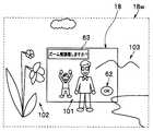
このように構成された本実施形態のカメラ1を用いて撮影を行なう際の作用を以下に説明する。図2は、本実施形態のカメラ1を用いて撮影を行なう際の撮影状況の概念図である。本実施形態のカメラ1を手に持つ使用者(ユーザー)100が、図2に示すように、主要な撮影対象としての二人の人物等101を含む光景を撮影するものとする。この場合において、本カメラ1による撮影範囲内には、主要撮影対象101と花等102と山等103が存在する状況を想定している。 An operation when photographing is performed using the camera 1 of the present embodiment configured as described above will be described below. FIG. 2 is a conceptual diagram of a shooting situation when shooting is performed using the camera 1 of the present embodiment. Assume that a user (user) 100 holding the camera 1 according to the present embodiment photographs a scene including two
図3は、本実施形態のカメラにおけるカメラ制御の処理シーケンスを示すフローチャートである。図4は、図3の処理シーケンスのうちのサブルーチン(ステップS117の処理)を示すフローチャートである。 FIG. 3 is a flowchart showing a camera control processing sequence in the camera of this embodiment. FIG. 4 is a flowchart showing a subroutine (processing of step S117) in the processing sequence of FIG.
まず、本実施形態のカメラ1が電源オン状態とされて動作可能な起動状態にあるものとする。この状態にあるとき、ステップS101において、信号処理制御部11は、現在設定されている動作モードが撮影モードにあるか否かの確認を行なう。ここで、撮影モードに設定されていることが確認された場合には、次のステップS102の処理に進む。また、撮影モード以外に設定されていることが確認された場合には、ステップS151の処理に進む。 First, it is assumed that the camera 1 of the present embodiment is in an activated state in which the camera 1 is turned on and can operate. In this state, in step S101, the signal
ステップS102において、信号処理制御部11は、撮像素子13及びレンズ26等からなる撮像部と表示部18等を制御して画像データの取得処理及びライブビュー画像表示処理を実行する。その後、ステップS111の処理に進む。 In step S102, the signal
続いて、ステップS111において、信号処理制御部11は、ボディ側通信部12を制御してレンズ側通信部22を介してレンズ鏡筒20のレンズ制御部21との間でレンズ通信処理を行なう。このレンズ通信処理において、カメラボディ10に装着されているレンズ鏡筒20の種類等のレンズ情報の取得等が行われる。 Subsequently, in step S <b> 111, the signal
なお、上記レンズ通信処理においては、カメラボディ10にレンズ鏡筒20が装着されているか否かの確認や、レンズ交換操作が行なわれたか否か等の確認も合わせて行なう。ここで、例えばボディ側通信部12とレンズ側通信部22との通信が確立できない場合には、カメラボディ10にレンズ鏡筒20が装着されていないものと判断し、その場合には、信号処理制御部11は、表示制御部11dを介して表示部18を制御して、その旨の警告表示等を表示する制御を行ない、これにより使用者(ユーザー)にレンズ鏡筒20の装着を促す。そして、レンズ装着の確認を待って、レンズ通信処理を実行する。また、レンズ通信処理が行われることによって、現在、カメラボディ10側の信号処理制御部11が保持しているレンズ鏡筒20に関するレンズ情報と、レンズ通信処理の結果、現在カメラボディ10に装着されているレンズ鏡筒20側から取得したレンズ情報とが一致しない場合には、レンズ交換操作が行なわれたものと判断し、その場合には、信号処理制御部11は、新たに取得したレンズ情報を一時記録部16等に一時記録する等の処理を行なう。その後、ステップS116の処理に進む。 In the lens communication process, confirmation as to whether or not the lens barrel 20 is attached to the camera body 10 and whether or not a lens exchange operation has been performed are also performed. Here, for example, when communication between the body
ステップS116において、信号処理制御部11は、通信部12,22を介してレンズ制御部21との通信を行なって、第1回動検出部27a,第2回動検出部27bからの信号を監視して、上記フォーカスリング23a(第1操作リング),上記ズームリング23b(第2操作リング)が操作されたか否かの確認を行なう。ここで、上記両リング23a,23bの少なくとも一方若しくは両方の操作が確認された場合には、次のステップS117の処理に進む。また、上記両リング23a,23bのいずれの操作も確認されない場合には、ステップS118の処理に進む。 In step S116, the signal
次の、ステップS117において、信号処理制御部11は、リング操作検出処理のサブルーチン(図4の処理シーケンス)を実行する。その後、ステップS118の処理に進む。なお、上記ステップS117の処理の詳細は、図4を用いて後述する。 In the next step S117, the signal
次に、ステップS118において、信号処理制御部11は、現在設定されている撮影処理に関する動作モードが静止画撮影モードに設定されているか否かの確認を行なう。ここで、静止画撮影モードに設定されていることが確認された場合には、次のステップS119の処理に進む。また、静止画撮影モード以外の動作モードが設定されている場合には、ステップS121の処理に進む。 Next, in step S118, the signal
ステップS119において、信号処理制御部11は、所定の静止画撮影処理を実行する。この静止画撮影処理のシーケンスは、従来一般のカメラで行われる処理と同様である。したがって、その詳細説明は省略する。 In step S119, the signal
上述のステップS118の処理にて、静止画撮影モード以外の動作モード設定が確認されて、ステップS121の処理に進むと、このステップS121において、信号処理制御部11は、現在設定されている撮影処理に関する動作モードが動画撮影モードに設定されているか否かの確認を行なう。ここで、動画撮影モードに設定されていることが確認された場合には、次のステップS122の処理に進む。また、動画撮影モード以外の動作モード、即ち静止画撮影モードが設定されている場合には、上述のステップS101の処理に戻る。 When the operation mode setting other than the still image shooting mode is confirmed in the process of step S118 described above and the process proceeds to step S121, in step S121, the signal
ステップS122において、信号処理制御部11は、所定の動画撮影処理のシーケンスを開始する。この動画撮影処理のシーケンスも、従来一般のカメラで行われる処理と同様である。したがって、その詳細説明は省略する。 In step S122, the signal
なお、上述のステップS122の動画撮影処理が開始されると、次のステップS123において、信号処理制御部11は、操作部15からの指示信号を監視し、その処理の間中、常に動画撮影処理の終了指示信号の確認を続ける。ここで、動画撮影処理の終了を指示する指示信号が確認された場合には、ステップS124の処理に進む。また、動画撮影処理終了指示信号が確認されない場合には、上述のステップS102の処理に戻り、以降の処理を繰り返す。 When the moving image shooting process of step S122 described above is started, in the next step S123, the signal
そして、ステップS124において、信号処理制御部11は、動画撮影処理の終了処理を実行した後、記録部14を制御して取得済みの画像データを記録する処理を実行する。その後、ステップS101の処理に戻る。 In step S124, the signal
一方、上述のステップS101の処理にて、カメラ1に設定されている動作モードが撮影モード以外であることが確認されて、ステップS151の処理に進むと、このステップS151において、信号処理制御部11は、現在設定されている動作モードが再生モードであるか否かの確認を行なう。ここで、再生モードに設定されていることが確認された場合には、所定の再生処理シーケンスへ移行するものとし、ステップS152の処理に進む。 On the other hand, when it is confirmed in the process of step S101 described above that the operation mode set in the camera 1 is other than the shooting mode and the process proceeds to the process of step S151, the signal
ステップS152において、信号処理制御部11は、記録部14を制御して記録媒体に記録済みの画像データのサムネイル画像データを読み出して、所定の信号処理を施した後、表示制御部11dを介して表示部18を制御してファイル一覧表示処理を実行する。なお、このファイル一覧表示処理に代えて、次のような表示処理を実行するようにしてもよい。即ち、カメラ1が再生モードにあることが確認されると、信号処理制御部11は記録部14を制御して記録媒体に記録済みの画像データのうち最新画像データを読み出して、所定の信号処理を施した後、表示制御部11dを介して表示部18を制御して最新画像の再生処理を実行するようにしてもよい。その後、ステップS153の処理に進む。 In step S152, the signal
続いて、ステップS153において、信号処理制御部11は、操作部15若しくはタッチパネル18bからの指示信号を監視して、ファイル選択指示信号が発生したか否かの確認を行なう。ここで、ファイル選択指示信号は、表示中のファイル一覧のうちのいずれかを選択する旨の指示信号である。なお、最新画像表示の場合には、表示中の画像データの一つ前の画像データ若しくは記録済み画像データ中の最も古い画像データのいずれかを選択指示する指示信号となる。このステップS153の処理にて、信号処理制御部11がファイル選択指示信号の発生を確認した場合には、次のステップS154の処理に進む。また、ファイル選択指示信号が確認されない場合には、ステップS156の処理に進む。 Subsequently, in step S153, the signal
次に、ステップS154において、信号処理制御部11は、記録部14を制御して記録媒体に記録済みの画像データのうち上述のステップS153の処理にて選択された画像データを読み出して、所定の信号処理を施した後、表示制御部11dを介して表示部18を制御して選択画像の再生処理を実行する。その後、ステップS155の処理に進む。 Next, in step S154, the signal
ステップS155において、信号処理制御部11は、操作部15若しくはタッチパネル18bからの指示信号を監視して、選択画像の表示を終了させる旨の指示信号が発生したか否かの確認を行なう。このステップS155において、選択画像表示終了指示信号が確認されない場合には、上述のステップS154の処理に戻る。即ち、同じ選択画像の表示処理を続行し続ける。また、選択画像表示終了指示信号が確認された場合には、ステップS152の処理に戻り、以降の処理を繰り返す。 In step S155, the signal
一方、上述のステップS153の処理にて、ファイル選択指示信号が確認されずにステップS156の処理に進むと、このステップS156において、信号処理制御部11は、操作部15若しくはタッチパネル18bからの指示信号を監視して、再生モードの終了指示信号が発生したか否かの確認を行なう。ここで、再生モード終了指示信号は、例えばモード切換操作若しくは電源オフ操作等である。このステップS156において、再生モード終了指示信号が確認されない場合には、上述のステップS152の処理に戻り、以降の処理を繰り返す。また、再生モード終了指示信号が確認された場合には、ステップS101の処理に戻り、以降の処理を繰り返す。なお、再生モード終了指示信号の発生トリガーとして、電源オフ操作が行なわれた場合には、全ての動作を終了するものとして、本カメラ制御処理シーケンスを終了する。この処理シーケンスについては、図3においては図面の煩雑化を避けるために図示を省略している。 On the other hand, if the file selection instruction signal is not confirmed in step S153 and the process proceeds to step S156, in step S156, the signal
他方、上述のステップS151の処理にて再生モード以外に設定されていることが確認された場合には、他の動作モードへの移行処理シーケンスを実行する。ここで、他の動作モードとしては、例えば画像通信モード等があるが、これらの他の動作モードについては、本発明に直接関係しないので、その詳細説明は省略し、再生モード以外に設定されている場合の処理シーケンスとしては、便宜的に上述のステップS101の処理に戻るようにしている。 On the other hand, when it is confirmed in the process of step S151 described above that the mode is set to a mode other than the playback mode, a transition process sequence to another operation mode is executed. Here, other operation modes include, for example, an image communication mode. However, since these other operation modes are not directly related to the present invention, a detailed description thereof will be omitted, and a mode other than the playback mode is set. For convenience, the processing sequence returns to the processing in step S101 described above.
本実施形態のカメラ1における上述のような一連の再生処理シーケンスは、従来一般的な形態のカメラと同様である。 A series of playback processing sequences as described above in the camera 1 of the present embodiment is the same as that of a conventional general camera.
なお、本実施形態のカメラ1の信号処理制御部11は、常に操作部15若しくはタッチパネル18b等からの指示信号を監視している。そして、上記処理シーケンス中のいずれの時点においても、操作部15若しくはタッチパネル18b等からの指示信号が確認された場合には、確認した指示信号に対応する処理を割り込ませるように構成している。したがって、カメラ1の動作状況に関らず、所定の割り込み信号(例えば電源オフ信号,リセット信号,動作切換信号等)が確認された場合には、実行中の処理を中断させ、若しくは実行中の処理の終了を待って、割り込み指示に応じた処理(例えば電源オフ処理,リセット処理,動作切換処理等)を実行する。 Note that the signal
次に、本実施形態のカメラにおけるリング操作検出処理のサブルーチン(図3のステップS117の処理)の詳細を、図4を用いて以下に説明する。 Next, details of the subroutine of the ring operation detection process (the process of step S117 in FIG. 3) in the camera of the present embodiment will be described below with reference to FIG.
上述したように、上述の図3のステップS116の処理にて、上記二つの操作リング23a,23bのいずれか若しくは両方が操作されて、ステップS117の処理、即ち図4の処理シーケンスに移行する。 As described above, either or both of the two operation rings 23a and 23b are operated in the process of step S116 of FIG. 3 described above, and the process proceeds to the process of step S117, that is, the process sequence of FIG.
まず、図4のステップS301において、信号処理制御部11は、上述のステップS116の処理による検出結果について、上記二つの操作リング23a,23bが同時に回動操作されたものであるか否かの確認を行なう。ここで、上記二つの操作リング23a,23bの同時回動操作であることが確認された場合には、信号処理制御部11は、各操作リング23a,23bへの回動操作に対応する制御を禁止した上で、次のステップS311の処理に進む。ここで、上記二つの操作リング23a,23bの同時回動操作が検出されると、各操作リングの回動操作に対応する制御を禁止しているのは、次のような理由による。即ち、二つの操作リング23a,23bの同時回動操作が検出された場合、その操作が意図したものであるか、誤操作によるものであるかの判断がつかない。そのために、その同時回動操作が誤操作によるものであったとしても、現在設定されているフォーカス設定やズーム設定が意図せずにズレてしまうことを防止するために、この処理ステップの段階では、同時回動操作に対応する制御を禁止している。 First, in step S301 in FIG. 4, the signal
一方、ここで、操作リングの同時回動操作ではないことが確認された場合、例えば上記二つの操作リング23a,23bの一方のみの操作が確認された場合には、ステップS302の処理に進む。 On the other hand, when it is confirmed that the operation ring is not simultaneously rotated, for example, when only one of the two operation rings 23a and 23b is confirmed, the process proceeds to step S302.
ステップS311において、信号処理制御部11は、現在ズーム微調モードに設定されているか否かの確認を行なう。ここで、現在既にズーム微調モードに設定されている場合には、ステップS312の処理に進む。 In step S311, the signal
続いてステップS312において、信号処理制御部11は、現在設定されているズーム微調モードを解除して、通常のズーム制御モードへの設定切り換えを行う。その後、元の処理シーケンス(図3)に戻り、図3のステップS118の処理に進む。なお、上記ステップS312の処理にてズーム微調モードの解除処理の前に、表示部18にその旨(ズーム微調モードを解除して通常ズーム制御モードに切り換える旨)の警告表示を行なうようにして、使用者の諾否を問うようにしてもよい。 Subsequently, in step S312, the signal
一方、上述のステップS311の処理にて、現在ズーム微調モードに設定されておらず、通常ズーム制御モードが設定されている場合には、ステップS320の処理に進む。 On the other hand, if the zoom fine adjustment mode is not currently set and the normal zoom control mode is set in the process of step S311, the process proceeds to step S320.
ステップS320において、信号処理制御部11は、ズーム制御をズーム微調モードへと切り換えるズーム微調モード切換処理の実行を開始する。 In step S320, the signal
次いで、ステップS321において、信号処理制御部11は、表示制御部11dを介して表示部18を制御して表示部18の表示画面に所定のアイコン表示処理を実行する。ここで表示されるアイコンデータは、例えば記録部14等に予め記録されているデータを用いる。 Next, in step S321, the signal
ここで、ズーム微調モード時のライブビュー画像の表示画面と、その動作時の概念を説明する。図5は、本実施形態のカメラ1によって上述の図2に示す状況を撮影対象とする際の撮影範囲を示す概念図である。図5において、点線で示し符号18wを附した矩形枠は、本実施形態のカメラ1のレンズ鏡筒20の撮影光学系を最も短焦点端(最広角端)に設定して得られる撮影範囲を示す撮影枠とする。また、図5において、実線で示し符号18を附した矩形枠を表示部18の表示画面に表示されるライブビュー画像の表示範囲(撮影範囲;撮影枠)としている。つまり、図5において、表示部18で示されるライブビュー画像は、本カメラ1のレンズ鏡筒20によって設定し得るズーム範囲のうち最広角端よりも所定量だけズーミングしている状態を示している。 Here, a live view image display screen in the zoom fine adjustment mode and a concept during the operation will be described. FIG. 5 is a conceptual diagram illustrating a shooting range when the camera 1 according to the present embodiment targets the situation illustrated in FIG. 2 as a shooting target. In FIG. 5, a rectangular frame indicated by a dotted line and denoted by
カメラ1の使用中において、撮影光学系が任意のズーム位置に設定されている状態にある時、図4のステップS320の処理(ズーム微調モード切換処理)が実行されると、表示部18の表示画面は、図5の実線で示す符号18の矩形枠の状態となり、使用者による操作入力待ちの状態になる。このとき、表示部18の表示画面には、撮影対象のライブビュー画像に重畳させて、表示画面内の所定の領域に、「ズーム微調整しますか?」等の説明表示63と、「OK」アイコン62等が表示される(図4のステップS321の処理;後述)。 When the camera 1 is in use and the photographic optical system is set to an arbitrary zoom position, if the process in step S320 (zoom fine adjustment mode switching process) in FIG. The screen is in a state of a rectangular frame indicated by a
この表示画面の表示中に使用者は、例えばタッチパネル18bを介して上記「OK」アイコン62をタッチ操作するか、若しくはカメラボディ10側の操作部15に含まれるOKボタン(不図示)等を操作することによって、ズーム微調モードへの切り換えを受け入れる。これによって、カメラ1のズーム制御モードはズーム微調モードへと切り換わる。また、使用者がズーム微調モードへの切り換えを受け入れない場合には、使用者は、この表示画面の表示中にその旨の操作、例えばタッチパネル18bを介して上記「OK」アイコン62以外の領域の所定の操作、若しくはカメラボディ10側の操作部15に含まれる所定の操作部材等を操作することによって、当該処理をキャンセルすることができる While the display screen is displayed, the user touches the “OK”
即ち、図4のステップS322において、信号処理制御部11は、タッチパネル18b若しくは操作部15からの指示信号を監視して、「OK」指示が生じたか否かの確認を行う。ここで、「OK」指示が確認された場合には、使用者によってズーム微調モードへの切換処理が受け入れられたものとして、次のステップS323の処理に進む。また、「OK」指示が確認されない場合には、使用者によってズーム微調モードへの切換処理が受け入れられなかったものとして、所定のキャンセル処理を実行して、図4の処理シーケンスを抜け、元の処理シーケンス(図3)に戻り、図3のステップS118の処理に進む。 That is, in step S322 of FIG. 4, the signal
このようにして、使用者によってズーム微調モードへの切換処理が受け入れられると、続いて、ステップS323において、信号処理制御部11は、通信部12,22を介してレンズ鏡筒20のレンズ制御部21との通信を行う。そして、信号処理制御部11は、レンズ制御部21を介してズーム駆動部24aを制御してズーム駆動機構部26aによるズーム光学系のズーム駆動制御を行なって、ズーム設定を最広角端(ワイド端)に設定する(図6参照)。 In this way, when the switching process to the zoom fine adjustment mode is accepted by the user, subsequently, in step S323, the signal
続いて、ステップS324において、信号処理制御部11は、表示制御部11dを介して表示部18を制御して表示部18の表示画面に、ズーム範囲指定するための指示表示、即ちズーム微調モード用のアイコン表示処理を実行する。ここで表示されるアイコンデータは、例えば記録部14等に予め記録されているデータを用いる。ここで、信号処理制御部11は、使用者による操作入力待ち状態になる。ここで、使用者は、タッチパネル18bへの二つの点を指定するタッチ操作を行うことで、ズーム微調モード時における所望のズーム範囲を指定する。 Subsequently, in step S324, the signal
ここで、図6,図7は、本実施形態のカメラ1において、ズーム微調モードで動作している際のライブビュー画像表示の一例を示している。このうち、図6は、ズーム微調モードで動作中のライブビュー画像を示し、その状況下においてズーム微調整のための所望のズーム範囲を設定操作している際のようすを示している。また、図7は、図6の設定操作の結果、変化した後のライブビュー画像の表示例を示している Here, FIGS. 6 and 7 show an example of live view image display when the camera 1 of the present embodiment is operating in the zoom fine adjustment mode. Among these, FIG. 6 shows a live view image that is operating in the zoom fine adjustment mode, and shows a state in which a desired zoom range for zoom fine adjustment is set and operated under the circumstances. FIG. 7 shows a display example of the live view image after the change as a result of the setting operation of FIG.
上述したように、図5の状況において、ズーム微調モードへのモード切り換え操作が行われると、表示部18のライブビュー画像は、図6に示す表示に変更される。即ち、上述の図4のステップS323の処理にてズーム駆動制御が行われて、ズーム設定が最広角端(ワイド端)に設定される。続いて、ステップS324の処理にて、ズーム範囲を指定するための所定のアイコン表示処理が実行される。この場合においては、撮影対象のライブビュー画像に重畳させて、表示画面内の所定の領域にズーム微調アイコン61と、「2点タッチしてください」等の説明表示64等が表示される(図7参照)。ここで、ズーム微調アイコン61は、図7に示すように円環形状の操作部材を模した円環部61aと、この円環部61aの周縁に沿う位置に複数(本例では二つ)の指標61bとからなる。 As described above, when the mode switching operation to the zoom fine adjustment mode is performed in the situation of FIG. 5, the live view image on the
この図6の表示画面の表示中に、使用者は手指等を用いて、表示部18の表示画面上の任意の2点をタッチパネル18bを介してタッチ操作する。例えば図6に示す例では、使用者は手指100によって、点Aと点Bとの二つの点をタッチ操作している状況を示している。ここで行うタッチ操作は、ズーム微調整のためのズーム範囲を設定する操作になる。つまり、現在設定されているズーム設定は、上述したように最広角端(ワイド端)であり、本カメラ1の撮影光学系によって設定し得る最も広角寄りの撮影範囲が表示されている。この撮影範囲のうちから、使用者が任意の2点をタッチ操作にて指定することによって所望のズーム範囲を設定するわけである。ここで示す例では、タッチ操作を行って指定する2点のうちの1点は、所望のズーム範囲のうち一方(短焦点(広角)寄り)の指定の画角により規定される撮影範囲の一隅とし、他の1点を所望のズーム範囲のうち他方(長焦点(望遠)寄り)の指定の画角により規定される撮影範囲の一隅として設定されるようにしている。これにより、タッチ操作による一方の指定点Aは、図7において点線で示される二つの矩形枠のうち符号18Aで示される一方の(短焦点(広角)寄りの)撮影範囲が設定され、他方の指定点Bは、図7において点線で示される二つの矩形枠のうち符号18Bで示される他方の(長焦点(望遠)寄りの)撮影範囲が設定されることになる。 While the display screen of FIG. 6 is being displayed, the user touches any two points on the display screen of the
このように、使用者がタッチ操作によって2点タッチ操作を行うことによって、ズーム微調整のためのズーム範囲が設定される。 Thus, when the user performs a two-point touch operation by a touch operation, a zoom range for fine zoom adjustment is set.
そして、図4のステップS325において、信号処理制御部11は、タッチ判定部11cからの指示信号の出力を監視して、2点のタッチ操作が行われたか否かの確認を行う。ここで、2点タッチ操作が確認された場合には、次のステップS326の処理に進む。また、予め設定された所定の時間内に2点タッチ操作が確認されない場合、若しくはキャンセル指示が確認されたような場合には、所定のキャンセル処理を実行して、図4の処理シーケンスを抜け、元の処理シーケンス(図3)に戻り、図3のステップS118の処理に進む。なお、上記所定の時間は、時計部19による計時を参照するものとする。また、キャンセル指示は、例えば同一点のダブルタップ操作等、所定の操作による指示信号や、操作部15の他の操作部材からの割り込み指示信号等とすればよい。 In step S325 of FIG. 4, the signal
続いて、ステップS326において、信号処理制御部11は、上述の2点タッチ操作による設定操作の結果に基いて、ズーム微調整のためのズーム設定範囲を決定し、表示制御部11dを介して表示部18を制御して、その旨の表示処理を実行する。このときの表示結果の例を図7に示す。図7に示す例では、ズーム微調整のためのズーム範囲を表わす二つの撮影範囲を、二つの矩形枠18A,18Bによって表示している。これに加えて、ズーム微調アイコン61の二つの指標61bのそれぞれから延出される矢印アイコン61cを表示している。この場合において、矢印アイコン61cの一方は、矩形枠18Aを指し示し、矢印アイコン61cの他方は、矩形枠18Bを指し示すように表示している。 Subsequently, in step S326, the signal
なお、上述のようにしてズーム微調整のためのズーム設定範囲が決定されると、信号処理制御部11は、レンズ制御部21を介してズーム駆動部24aを制御してズーム駆動機構部26aによるズーム光学系のズーム駆動制御を行なって、設定されたズーム範囲のうちの一方、例えば短焦点(広角)寄りのズーム設定とするようにしてもよい。この場合には、表示部18の全表示画面を使って一方の撮影範囲が表示され、他方の撮影範囲が点線による矩形枠18Bで表示される。 When the zoom setting range for fine zoom adjustment is determined as described above, the signal
この図7の表示画面の表示中において、使用者は、フォーカスリング23aを回動させることによって、設定されたズーム範囲内でズーミングの微調整を行うことができる(後述する図4のステップS303の処理)。この場合、フォーカスリング23aは、通常の動作モードとは異なり、ズーム駆動部24aを介してズーム駆動機構部26aを駆動させる操作部材として機能する。 While the display screen of FIG. 7 is displayed, the user can finely adjust the zooming within the set zoom range by rotating the
なお、ズーム微調整の操作手段としては、上記のフォーカスリング23aの操作とは別に、図7の表示画面上においてタッチパネル18b越しにズーム微調アイコン61の円環部61aに沿うタッチ&スライド操作としてもよい。 In addition to the operation of the
さらに、これらの操作とは別に、ズーム微調アイコン61の円環部61aと同様な形態のダイヤル状部材をカメラボディ10に設け、このダイヤル状部材を回動操作することによって、同様のズーム微調整の制御を行うような形態としてもよい。 Further, apart from these operations, a dial-like member having the same form as the
一方、上述のステップS301の処理にて、同時回動操作ではないことが確認されて、ステップS302の処理に進むと、このステップS302において、信号処理制御部11は、現在ズーム微調モードに設定されているか否かの確認を行なう。ここで、現在既にズーム微調モードに設定されている場合には、ステップS303の処理に進む。また、現在ズーム微調モードに設定されておらず、通常のズーム制御を行う通常ズーム制御モードに設定されていることが確認された場合には、ステップS305の処理に進む。 On the other hand, when it is confirmed in the process of step S301 that the simultaneous rotation operation is not performed and the process proceeds to step S302, the signal
ステップS303において、信号処理制御部11は、上述の図3のステップS116の処理による検出結果について、上記二つの操作リング23a,23bのうちのフォーカスリング23aが回動操作されたものであるか否かの確認を行なう。ここで、フォーカスリング23aの回動操作が確認されている場合には、ズーム微調整のためのズーミング操作が行われているものと判断して、次のステップS304の処理に進む。また、フォーカスリング23a以外、即ちズームリング23bの回動操作が確認されている場合には、ステップS305の処理に進む。 In step S303, the signal
ステップS305において、信号処理制御部11は、実行されたリング操作に応じて通常のフォーカス制御若しくはズーム制御を実行する。なお、これら通常のフォーカス制御,ズーム制御は、従来一般のカメラと同様の制御であるので、その詳細は省略する。 In step S305, the signal
上述のステップS305の処理について詳述する。上述したように、このステップS305の処理に入るためには、上記ステップS302の処理にてズーム微調モードではない(通常ズーム制御モードに設定されている)とされた場合、若しくは上記ステップS302の処理にてズーム微調モードであると確認されて、かつ上記ステップS303の処理にてズームリング23bの操作が確認された場合である。 The process of step S305 described above will be described in detail. As described above, in order to enter the process of step S305, when the zoom fine adjustment mode is not set (set to the normal zoom control mode) in the process of step S302, or the process of step S302 is performed. This is a case where it is confirmed that the zoom fine adjustment mode is selected and the operation of the
したがって、前者の場合、即ち通常ズーム制御モード時には通常の操作リングの操作に基く制御がなされる。また、後者の場合、即ちズーム微調モードに設定されている時にズームリング23bが操作された場合は、使用者の意志として、ズーム微調整を行わずに、例えば再度、ズーム微調整のためのズーム範囲の設定を行おうとしている等と判断されて、通常の操作リングの操作に基く制御がなされる。その後、元の処理シーケンス(図3)に戻り、図3のステップS118の処理に進む。 Therefore, in the former case, that is, in the normal zoom control mode, control based on the operation of the normal operation ring is performed. In the latter case, that is, when the
一方、上述のステップS303の処理にてフォーカスリング23aの回動操作によるズーム微調整操作が確認されてステップS304の処理に進むと、このステップS304において、信号処理制御部11は、上述のステップS303の処理によるフォーカスリング23aのズーム微調整操作の結果、ズーム位置がズーム設定範囲のうちの一方のズーム端に設定されているか否かの確認を行なう。ここで、ズーム設定範囲のうちのズーム端に到達していることが確認された場合には、次のステップS306の処理に進む。また、ズーム設定範囲内においてズーム端に到達していないことが確認された場合には、ステップS307の処理に進む。 On the other hand, when the zoom fine adjustment operation by the rotation operation of the
ステップS306において、信号処理制御部11は、ズーム設定範囲におけるズーム端とは別のズーム端となるようにズーム設定を変更する。この処理によって、フォーカスリング23aの一方向のみへの回動操作を続けたとしても、ズーム設定範囲内でのズーム操作をシームレスに継続して行なうことができるようになる。その後、元の処理シーケンス(図3)に戻り、図3のステップS118の処理に進む。 In step S306, the signal
他方、ステップS307において、信号処理制御部11は、フォーカスリング23aの回動操作に応じて、ズーム設定範囲内におけるズーム微調整制御を実行する。その後、元の処理シーケンス(図3)に戻り、図3のステップS118の処理に進む。 On the other hand, in step S307, the signal
なお、本実施形態においては、円環状操作部材からなる二つの操作リング23a,23bの同時回動操作をズーム微調モードへの切り換えのトリガーとしているが、この形態に限られることはない。例えば、カメラボディ10側に設けられる操作部15に含まれる押圧式ボタンやスライド摺動式等の複数の操作部材を同時に操作することをモード切り換えのトリガーとする形態としてもよい。 In the present embodiment, the simultaneous rotation operation of the two operation rings 23a and 23b made of the annular operation member is used as a trigger for switching to the zoom fine adjustment mode, but the present invention is not limited to this form. For example, a mode switching trigger may be configured by simultaneously operating a plurality of operation members such as a push button and a sliding slide included in the
以上説明したように上記第1の実施形態によれば、小型化により隣接して設けられる二つの操作リング23a,23bを同時に操作することによって、従来なかった動作モード(具体的にはズーム制御のうちのズーム微調モード)へとシームレスに切り換わるように構成している。この場合において、二つの操作リング23a,23bの同時操作を検出した時、各操作リング23a,23bによる通常の制御を禁止するように制御されている。このように、二つの操作リング23a,23bを同時操作すると、各操作リング23a,23bに割り当てられた通常の制御を禁止したので、たとえ二つの操作リング23a,23bの同時操作が誤操作であったとしても設定ずれ等の事故を防止することができると同時に、ズーム制御をズーム微調モードへとシームレスに移行させ得る。 As described above, according to the first embodiment, by operating the two operation rings 23a and 23b provided adjacent to each other by downsizing, an operation mode that has not existed in the past (specifically, zoom control is not possible). It is configured to seamlessly switch to (zoom fine adjustment mode). In this case, when the simultaneous operation of the two operation rings 23a and 23b is detected, the normal control by the operation rings 23a and 23b is controlled to be prohibited. As described above, when the two operation rings 23a and 23b are operated simultaneously, the normal control assigned to the operation rings 23a and 23b is prohibited, so that the simultaneous operation of the two operation rings 23a and 23b is erroneous. However, accidents such as setting deviation can be prevented, and at the same time, zoom control can be seamlessly shifted to the zoom fine adjustment mode.
そうして、ズーム微調モードへと切り換えた後は、表示部18の表示画面上で所望のズーム範囲を設定し、ズーム操作を行なうためのズームリング23bに隣接するフォーカスリング23aを回動操作することによってズーミングの微調整操作を行なうことができるように制御されている。 After switching to the zoom fine adjustment mode, a desired zoom range is set on the display screen of the
したがって、このズーム微調モードによるズーム制御では、使用者(ユーザー)が所望する撮影範囲の詳細なズーム制御を行って厳密なフレーミングを容易に行なうことができる。これによって、通常の電動ズーム制御に比べて、より簡単に所望の撮影範囲の設定(フレーミング)を行なうことができるので、画像表現の幅を広げ多彩な撮影画像を取得することができる。
[第2の実施形態]Therefore, in zoom control using this zoom fine adjustment mode, precise zooming can be easily performed by performing detailed zoom control of a photographing range desired by a user (user). As a result, a desired shooting range can be set (framing) more easily than in normal electric zoom control, so that a wide variety of captured images can be acquired.
[Second Embodiment]
次に説明する本発明の第2の実施形態は、ズーム微調モード時における表示形態が上述の第1の実施形態とは異なる例を示すものである。本実施形態の撮影機器(カメラ)自体の基本的な構成は、上述の第1の実施形態と略同様であり、カメラ制御シーケンスが若干異なるのみである。したがって、上述の第1の実施形態と同様の構成については図示を省略し同じ符号を用いて説明する。また、同様の処理シーケンスについてもその図示及び説明は省略し、異なる部分のみを以下に説明する。 The second embodiment of the present invention to be described next shows an example in which the display form in the zoom fine adjustment mode is different from that of the first embodiment. The basic configuration of the photographing apparatus (camera) itself of the present embodiment is substantially the same as that of the first embodiment described above, and only the camera control sequence is slightly different. Accordingly, the same components as those in the first embodiment described above are not illustrated and will be described using the same reference numerals. Also, illustration and description of similar processing sequences are omitted, and only different portions will be described below.
図8は、本発明の第2の実施形態の撮影機器(カメラ)におけるカメラ制御処理シーケンスを示すフローチャートである。また、図9〜図14は、本実施形態の撮影機器(カメラ)における撮影動作時の表示部の表示例である。このうち図9は、本撮影機器(カメラ)の表示部に表示されるラブビュー画像の一例を示している。図10〜図14は、本撮影機器(カメラ)におけるズーム微調モード時のラブビュー画像の一例をそれぞれ示している。このうち、図10はズーム微調モードへと切り換えた直後の表示部の表示例である。図11,図12はズーム微調モード時において設定操作中の状態を示している。図11は図10の状態から望遠側(長焦点側;テレ側)へズーム操作を行った場合の表示部の表示例である。図12は図10の状態から広角側(短焦点側;ワイド側)へズーム操作を行った場合の表示部の表示例である。図13,図14は、ズーム微調モード時にズーム駆動制御がなされた後の表示部18の表示状態の例を示している。図13は、図11の後の状態、一方のズーム端を図10のズーム位置に、他方のズーム端をテレ方向に回動させた図11の設定とした場合に、そのズーム範囲の略中心にズーム位置を設定した際の表示画面の例である。図14は、図12の後の状態、即ち一方のズーム端を図10のズーム位置に、他方のズーム端をワイド方向に回動させた図12の設定とした場合に、そのズーム範囲の略中心にズーム位置を設定した際の表示画面の例である。 FIG. 8 is a flowchart showing a camera control processing sequence in the photographing apparatus (camera) according to the second embodiment of the present invention. 9 to 14 are display examples of the display unit during the photographing operation in the photographing apparatus (camera) of the present embodiment. Among these, FIG. 9 shows an example of a love view image displayed on the display unit of the photographing apparatus (camera). 10 to 14 show examples of love view images in the zoom fine adjustment mode in the photographing apparatus (camera), respectively. Of these, FIG. 10 is a display example of the display unit immediately after switching to the zoom fine adjustment mode. 11 and 12 show a state during the setting operation in the zoom fine adjustment mode. FIG. 11 is a display example of the display unit when the zoom operation is performed from the state of FIG. 10 to the telephoto side (long focal point side: telephoto side). FIG. 12 is a display example of the display unit when the zoom operation is performed from the state of FIG. 10 to the wide angle side (short focus side; wide side). 13 and 14 show examples of the display state of the
本実施形態において、撮影対象とする範囲内には、図9のライブビュー画像に示すように、複数の人物等の被写体101が存在しているものとする。以下に説明する作用は、この状況において本実施形態のカメラ1を用いて撮影を行なうことを想定している。 In the present embodiment, it is assumed that there are a plurality of
まず、図8のステップS401において、信号処理制御部11は、現在の動作モードが撮影モードに設定されているか否かの確認を行なう。ここで、撮影モードに設定されていることが確認された場合には、次のステップS402の処理に進む。また、撮影モード以外に設定されていることが確認された場合には、ステップS421の処理に進む(図3のステップS101に相当)。 First, in step S401 of FIG. 8, the signal
ステップS402において、信号処理制御部11は、撮像部(撮像素子13,レンズ26等)と表示部18等を制御して画像データの取得処理及びライブビュー画像表示処理を実行する。その後、ステップS403の処理に進む(図3のステップS102に相当)。なお、本実施形態では、上述の実施形態におけるレンズ通信処理(図3のステップS111の処理)の図示を省略している。これは本発明に直接関連しない処理ステップであるという理由による。したがって、図8の処理シーケンスにおいて、ステップS402のライブビュー画像表示処理の後に、レンズ通信処理等を含めるようにしてもよい。 In step S402, the signal
続いて、ステップS403において、信号処理制御部11は、通信部12,22を介してレンズ制御部21との通信を行なって、第2回動検出部27bからの信号を監視して、上記ズームリング23bの操作状態を確認する。ここで、ズームリング23bの操作が確認された場合には、ステップS406の処理に進む。また、ズームリング23bの操作が確認されない場合には、ステップS404の処理に進む。 Subsequently, in step S403, the signal
ステップS404において、信号処理制御部11は、現在設定されているズーム制御に関するモード判定処理を実行する。ここで、既にズーム微調モードに設定されていることが確認された場合には、ステップS451の処理に進む。また、通常のズーム制御モードに設定されている場合には、ステップS405の処理に進む。 In step S404, the signal
ステップS405において、信号処理制御部11は、通信部12,22を介してレンズ制御部21との通信を行なって、第1回動検出部27aからの信号を監視して、上記フォーカスリング23aの操作状態を確認する。ここで、フォーカスリング23aの操作が確認された場合には、ステップS409の処理に進む。また、フォーカスリング23aの操作が確認されない場合には、ステップS410の処理に進む。 In step S405, the signal
ステップS409において、信号処理制御部11は、上述のステップS405の処理にて操作されたフォーカスリング23aの回動操作量に応じたフォーカス駆動処理を実行する。このフォーカス駆動処理は、通常の手動焦点調節操作(マニュアルフォーカス操作;MF操作)に応じて行われる通常のフォーカス駆動制御処理である(詳細は省略)。 In step S409, the signal
続いて、ステップS410において、信号処理制御部11は、操作部15,タッチパネル18b等からの指示信号を監視する。ここで、撮影動作の指示信号が確認されると、ステップS411の処理に進む。また、撮影動作の指示信号が確認されない場合には、ステップS401の処理に戻る。 Subsequently, in step S410, the signal
ステップS411において、信号処理制御部11は、通常の撮影動作を実行する。この撮影処理動作の処理シーケンスは、従来一般のカメラで行われる処理と同様であるものとし、その詳細説明は省略する。その後、ステップS401の処理に戻る。 In step S411, the signal
以上の処理シーケンス(S401〜S411)は、通常の動作モードにて通常の撮影を行う際の通常の処理シーケンスである。以下の処理シーケンスが、本発明に関連する部分、即ち本実施形態のカメラ1におけるズーム微調モード時の作用を表わす。 The above processing sequence (S401 to S411) is a normal processing sequence when normal shooting is performed in the normal operation mode. The following processing sequence represents a part related to the present invention, that is, an operation in the zoom fine adjustment mode in the camera 1 of the present embodiment.
即ち、上述のステップS403の処理にてズームリング23bの操作が確認されてステップS406の処理に進むと、このステップS406において、信号処理制御部11は、現在設定されているズーム制御に関するモード判定処理を実行する(上記ステップS404の処理と同様の処理)。ここで、既にズーム微調モードに設定されていることが確認された場合には、ステップS408の処理に進む。また、通常のズーム制御モードに設定されている場合、例えばカメラ1の起動直後の状態にある時などは、ステップS407の処理に進む。 That is, when the operation of the
ステップS407において、信号処理制御部11は、操作部15,タッチパネル18b,操作リング23等からの指示信号を監視してズーム制御に関するモード切換操作が行われたか否かの確認を行う。この場合において、ズーム制御のモード切換操作としては、例えば通常ズーム制御モードにある時にズームリング23bの往復回動操作を一定時間内に複数回繰り返すといった所定の操作等を想定している。 In step S407, the signal
例えば、ズームリング23bの往復回動操作を一定時間内に複数回繰り返す等の操作、具体的には例えばズームリング23bをワイド側とテレ側に小刻みに繰り返し回動操作するといった状況は、使用者がズームリング23bを用いて詳細なズーム操作を行おうとしているものと考えられる。ズームリング23bによるズーム操作は、スイッチのオンオフによる電動ズーム制御としていることから細かな駆動制御を行なうことができず所望のフレーミングを得るための制御が難しい。そこで、上述のように、ズームリング23bの往復回動操作等、所定の操作が行われたときには、ズーミングの微調整操作を行い得るズーム制御モード(ズーム微調モード)へとシームレスに切り換わるようにしている。 For example, a situation in which the reciprocating rotation operation of the
なお、ズーム制御のモード切換操作としては、ほかにも、例えば操作部15に含まれる所定の操作部材の操作やタッチパネル18bの所定の領域への操作、若しくは操作部材を押しながら操作リングを回転させる等、複数部材の組み合わせによる操作等、または隣接する二つの操作リング23a,23bの同時操作等であってもよい。 In addition, as the mode switching operation of the zoom control, for example, an operation of a predetermined operation member included in the
このステップS407の処理にて、ズーム制御のモード切換操作が確認されると、その操作は、ズーム微調モードへの切り換え操作であると判断されて、ステップS471の処理に進む。また、ズーム制御のモード切換操作が確認されない場合には、ステップS479の処理に進む。ここで、ズーム制御モード切換操作を行なった時点で設定されているズーム位置は、これから行おうとするズーム微調整のための基準位置、例えばズーム微調整を行う際のズーム範囲の一方のズーム端位置として設定されるようにしている。なお、ズーム微調整を行う際の基準位置としては、これに限らず、例えばモード切換操作時点で設定されているズーム位置(基準位置)をズーム微調整のズーム範囲の中央位置として設定するようにしてもよい。 When the zoom control mode switching operation is confirmed in the process of step S407, it is determined that the operation is a switching operation to the zoom fine adjustment mode, and the process proceeds to step S471. If the zoom control mode switching operation is not confirmed, the process proceeds to step S479. Here, the zoom position set when the zoom control mode switching operation is performed is a reference position for fine zoom adjustment to be performed, for example, one zoom end position in the zoom range when performing zoom fine adjustment. Is set as. The reference position for fine zoom adjustment is not limited to this. For example, the zoom position (reference position) set at the time of the mode switching operation is set as the center position of the zoom range for zoom fine adjustment. May be.
ステップS471において、信号処理制御部11は、表示制御部11dを介して表示部18を制御して、表示部18に表示中のライブビュー画像に重畳させてズーム微調モードに対応する表示画面(図10参照)を表示させる。 In step S471, the signal
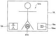
ここで、ズーム微調モード時の表示画面の形態として、例えば図10に示す表示例を説明する。図10において、表示部18には、引き続き撮影対象とする被写体101を含むライブビュー画像が表示されている。この表示に重畳させて、例えば図10の画面下縁寄りの略中央部にズーム微調アイコン61Aが表示される。ズーム微調アイコン61Aは、例えば図10に示すように、円環形状のリング部材(ズームリング23b等)を模した図形と、この円環状アイコンの近傍に表示される矢印を模した操作方向指示アイコン等からなる。なお、図10において「ZM」は「ズーム」を表わす文字アイコンの例示である。また「T」は「テレ(望遠)方向」を、「W」は「ワイド(広角)方向」表わす文字アイコンの例示である。 Here, as a form of the display screen in the zoom fine adjustment mode, for example, a display example shown in FIG. 10 will be described. In FIG. 10, the live view image including the subject 101 to be photographed is continuously displayed on the
また、図10に示すように、上記ズーム微調アイコン61Aを挟むようにして、下縁寄りの両隅部近傍の各々には、矩形枠状の小窓18t,18wが表示される。この二つの小窓18t,18wは、ズーム微調モード時におけるズーム設定に応じて変化する撮影範囲の目安を表示するための領域としている。具体的には、一方の小窓18tには、望遠側にズーミングした時の撮影範囲が表示される。また、他方の小窓18wには、広角側にズーミングした時の撮影範囲が表示される。 As shown in FIG. 10, rectangular frame-shaped
上述のステップS471の処理においては、さらに、信号処理制御部11は、表示制御部11dを介して表示部18を制御して、上記小窓18t,18wの両方に現在設定されているズーム設定に応じた撮影範囲の画像、即ちライブビュー画像と略同じ画像を表示させる。図10に示す例は、ズーム微調モードに設定した直後の状態を示している。したがって、二つの小窓18t,18wの各々には、表示部18に表示中のライブビュー画像と同等の画像が表示されている。つまり、この時点においては、ズーム微調モード設定直後でズーム操作も行われていない状態であるので、小窓18t,18wの各々には同じ画像が表示されている。 In the process of step S471 described above, the signal
図8に戻って、上述したように、ステップS407の処理にてモード切換操作が行われなかった場合の後、及びステップS471の処理にてモード切換処理が完了した場合の後、ステップS479の処理に進む。 Returning to FIG. 8, as described above, after the mode switching operation is not performed in the process of step S407 and after the mode switching process is completed in the process of step S471, the process of step S479 is performed. Proceed to
ステップS479において、信号処理制御部11は、ズームリング23bの回動操作に応じた通常のズームレンズ駆動制御処理を実行する。その後、ステップS410の処理に進む。 In step S479, the signal
上述のステップS471のモード切換処理によって、ズーム微調モードが設定された後、ズーム微調モード時の設定操作が行われている場合においては、ステップS479からステップS410を経てステップS404に戻った後、再度ステップS406の処理に戻り、このステップS406の処理にて、現在のズーム微調モードに設定されていることが確認されてステップS408の処理に進む。 In the case where the setting operation in the zoom fine adjustment mode is performed after the zoom fine adjustment mode is set by the mode switching process in step S471 described above, the process returns from step S479 to step S410 to step S404, and then again. Returning to the process of step S406, it is confirmed in the process of step S406 that the current zoom fine adjustment mode is set, and the process proceeds to step S408.
そして、このステップS408において、信号処理制御部11は、操作部15,タッチパネル18b,操作リング23等からの指示信号を監視して、ズーム微調モードを解除する操作が行われたか否かの確認を行う。この場合において、ズーム微調モード解除操作としては、例えばフォーカスリング23aの回動操作とズームリング23bとの回動操作を行なう操作のほか、操作部15のうちの所定の操作部材の操作、若しくはタッチパネル18bへの所定の領域へのタッチ操作等である。ここで、ズーム微調モード解除操作が確認された場合には、ステップS485の処理に進む。また、ズーム微調モード解除操作が確認されない場合には、ステップS481の処理に進む。 In step S408, the signal
ズーム微調モードでの作用を引き続き行う場合、即ち、上記ステップS408の処理にて、モード解除指示が確認されず、ズーム微調モードが継続されていると判断されて、次のステップS481の処理に進むと、このステップS481において、信号処理制御部11は、第2回動検出部27bからの信号を監視してズームリング23bの回動方向を確認する。ここで、ズームリング23bの回動方向がテレ(Tele)方向であると確認された場合には、ステップS482の処理に進む。また、ズームリング23bの回動方向がワイド(Wide)方向であると確認された場合には、ステップS483の処理に進む。 When the operation in the zoom fine adjustment mode is to be continued, that is, in the process of step S408, it is determined that the mode fine release mode is continued without confirming the mode release instruction, and the process proceeds to the next step S481. In step S481, the signal
続いてステップS482において、信号処理制御部11は、ズームリング23bのテレ(Tele)方向への回動操作に応じた所定のズーム駆動制御を行うと共に、表示制御部11dを介して表示部18を制御して対応するライブビュー画像を表示する。これと同時に、テレ(Tele)側の小窓18tの撮影範囲の表示変更処理(画角変更処理)を行う。この場合において、ズームリング23bのテレ(Tele)方向への回動操作が停止された時点のズーム位置を、ズーム微調整のためのズーム範囲の他方のズーム端位置に設定する。その後、ステップS489の処理に進む。 Subsequently, in step S482, the signal
図11は、表示部18の表示画面が図10の状態にあるときに、ズームリング23bをテレ(Tele)方向へ回動操作することによって実行される処理(ステップS482の処理)に応じて変化した後の表示画面の一例を示している。図11に示すように、ライブビュー画像は図10に比べて拡大された被写体101tが表示され、これに対応する画像が小窓18tに表示されている。これと同時に、図11において、小窓18wには、上述のステップS407,S471の処理の時点で設定された一方のズーム端位置(基準位置)に対応する画角を示す枠表示18waが表示されている。つまり、図11の小窓18wは、本カメラ1の撮影光学系により撮影し得る最広角端に設定した時の全撮影範囲を示し、その範囲内において、設定されたズーム端位置に対応する撮影範囲を枠表示18waで示している。 FIG. 11 changes according to the process (the process of step S482) executed by rotating the
また、ステップS483においては上述のステップS482と略同様に、信号処理制御部11は、ズームリング23bのワイド(Wide)方向への回動操作に応じた所定のズーム駆動制御を行うと共に、表示制御部11dを介して表示部18を制御して対応するライブビュー画像を表示する。これと同時に、ワイド(Wide)側の小窓18wの撮影範囲の表示変更処理(画角変更処理)を行う。この場合において、ズームリング23bのワイド(Wide)方向への回動操作が停止された時点のズーム位置を、ズーム微調整のためのズーム範囲の他方のズーム端位置に設定する。その後、ステップS489の処理に進む。 In step S483, in substantially the same manner as in step S482 described above, the signal
図12は、表示部18の表示画面が図10の状態にあるときに、ズームリング23bをワイド(Wide)方向へ回動操作することによって実行される処理(ステップS483の処理)に応じて変化した後の表示画面の一例を示している。図12に示すように、ライブビュー画像は図10に比べて縮小された被写体101wが表示され、これに対応する画像が小窓18wに表示されている。これと同時に、図12において、小窓18tには、上述のステップS407,S471の処理の時点で設定された一方のズーム端位置(基準位置)に対応する撮影範囲の画像が表示されている。 FIG. 12 changes according to the process (the process of step S483) executed by rotating the
ステップS489において、信号処理制御部11は、所定の変更フラグを設定する。ここで、変更フラグとは、ズーム微調モードにおけるズーム微調整のためのズーム範囲(の両端位置)が設定済みであることを示すフラグである。 In step S489, the signal
このようにしてステップS489の処理が完了すると、ズーム微調モード時のズーム範囲の設定が行われる。続いてズーム微調モード時においてズーム微調整を行う際の作用は次のようになる。 When the process of step S489 is completed in this way, the zoom range in the zoom fine adjustment mode is set. Subsequently, the operation when performing zoom fine adjustment in the zoom fine adjustment mode is as follows.
上述のステップS489の処理が完了することによってズーム微調モードのズーム範囲の設定が完了すると、ステップS479を経てステップS410の判断の後、ステップS403に戻り、次いでステップS404の処理に進み、このステップS404のモード判定処理にて、既にズーム微調モードに設定済みであることが確認されてステップS451の処理に進む。 When the setting of the zoom range in the zoom fine adjustment mode is completed by completing the process in step S489 described above, the process returns to step S403 after the determination in step S410 through step S479, and then proceeds to the process in step S404. In the mode determination process, it is confirmed that the zoom fine adjustment mode has already been set, and the process proceeds to step S451.
すると、このステップS451において、信号処理制御部11は、変更フラグの確認を行う。ここで、変更フラグが確認された場合には、ステップS452の処理に進む。また、変更フラグが確認されない場合には、ステップS454の処理に進む。 Then, in step S451, the signal
ステップS452において、信号処理制御部11は、レンズ制御部21を介してズーム駆動部24aを制御してズーム駆動機構部26aによるズーム光学系のズーム駆動制御を行って、両端が設定されたズーム範囲の略中心にズーム光学系のズーム位置を設定するための画角変更処理を行う。 In step S452, the signal
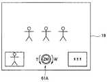
ここで、図13,図14は、ズーム微調モード時においてズーム駆動制御がなされた時の表示部18の表示状態の例を示している。図13は、図11の後の状態、即ち一方のズーム端を図10のズーム位置に、他方のズーム端をテレ方向に回動させた図11の設定とした場合に、そのズーム範囲の略中心にズーム位置を設定した際の表示画面の例である。また、図14は、図12の後の状態、即ち一方のズーム端を図10のズーム位置に、他方のズーム端をワイド方向に回動させた図12の設定とした場合に、そのズーム範囲の略中心にズーム位置を設定した際の表示画面の例である。 Here, FIGS. 13 and 14 show examples of the display state of the
なお、図13,図14に示すように、ズーム微調モード時において、ズーム範囲の設定が完了した後には、ズーム微調整操作を補助するために、アイコン61Aの近傍に回転方向を示す矢印等のガイド表示が表れるようにしている。ここで、矢印表示は回転方向を示す表示である。この矢印方向に附された「T」,「W」等のガイド表示は、それぞれ「テレ」,「ワイド」を意味する表示である。したがって、使用者は、表示部18の表示を見るだけで、直感的にズーム微調整の操作方法がわかり、例えば、微調整を行いたい所望の方向に対応する矢印表示に従ってリング回動操作を行えばよいように表示の工夫がなされている。 As shown in FIGS. 13 and 14, in the zoom fine adjustment mode, after the setting of the zoom range is completed, an arrow indicating the rotation direction is provided in the vicinity of the
続いて、ステップS453において、信号処理制御部11は、変更フラグをクリアして、次のステップS454の処理に進む。 Subsequently, in step S453, the signal
本実施形態のカメラ1においては、フォーカスリング23aを用いてズーム微調整のための操作を行うこととしている。そこで、次のステップS454の処理にて、フォーカスリング23aの回動操作の確認を行う。 In the camera 1 of the present embodiment, an operation for fine zoom adjustment is performed using the
即ち、ステップS454において、信号処理制御部11は、通信部12,22を介してレンズ制御部21との通信を行なって、第1回動検出部27aからの信号を監視して、上記フォーカスリング23aの操作状態を確認する。ここで、フォーカスリング23aの操作が確認された場合には、ステップS455の処理に進む。また、フォーカスリング23aの操作が確認されない場合には、ステップS410の処理に進む。 That is, in step S454, the signal
ステップS455において、信号処理制御部11は、フォーカスリング23aの回動操作に応じてレンズ制御部21を介してズーム駆動部24aを制御してズーム駆動機構部26aによるズーム光学系の所定のズーム駆動制御を実行する。 In step S455, the signal
つまり、本実施形態のカメラ1においては、ズーム微調モードにある時にフォーカスリング23aが操作されると、そのフォーカスリング23aの回動操作指示に応じたズーム駆動制御を実行する。その後、ステップS410の処理に進む。 That is, in the camera 1 of the present embodiment, when the
なお、上述のステップS408の処理にてモード解除指示が確認されて、次のステップS485の処理に進むと、このステップS485において、信号処理制御部11は、ズーム制御モードの設定を通常ズーム制御モードへと変更するモード変更処理を実行する。 When the mode cancellation instruction is confirmed in the process of step S408 described above and the process proceeds to the next step S485, in step S485, the signal
続いて、ステップS486において、信号処理制御部11は、表示制御部11dを介して表示部18を制御して、ズーム微調モード用のアイコン表示(61A,18t,18w等)の表示を消去する。これにより、表示部18の表示は、通常のライブビュー画像のみが表示される状態、即ち、図9に示す状態に戻る。その後、ステップS479の処理に進む。 Subsequently, in step S486, the signal
また、上述のステップS401の処理にて、カメラ1に設定されている動作モードが撮影モード以外であることが確認されて、ステップS421の処理に進むと、このステップS421において、信号処理制御部11は、現在の動作モードが再生モードであると判断し、所定の再生処理を実行する。ここで、所定の再生処理とは、従来のカメラにて行われる再生処理であるものとする。この再生処理については、本実施形態には直接関連しない部分であるので、その詳細説明は省略する。また、再生モード以外に設定されている場合の処理シーケンスについても、本実施形態には直接関連しない部分であることから、その図示及び詳細説明は省略する。この再生処理が終了したら、上述のステップS401の処理に戻る。 Further, when it is confirmed in the process of step S401 described above that the operation mode set in the camera 1 is other than the shooting mode, and the process proceeds to the process of step S421, the signal
なお、ズーム微調モード時のフォーカスリング23aのリング回転量と画角の変化量との関係は、例えば図15に示すように、1:1の関係(図中符号A)となるように制御してもよい。また、ワイド寄りのズーム端部近傍では荒く、テレ寄りのズーム端近傍では細かい微調整を行い得るような関係(図中符号B2)とする制御としてもよい。これとは逆に、ワイド寄りのズーム端部近傍では細かい微調整を行い得るようにし、テレ寄りのズーム端近傍では粗い画角変化とする関係(図中符号B1)とする制御としてもよい。 It should be noted that the relationship between the ring rotation amount of the
また、リング回転速度と画角変化速度との関係については、図16に示すように、リニアな関係(図中符号C)で制御してもよいし、遅い速度でリングを回動させると画角変化が少なくする一方、早い速度でリングを回転させると画角変化も大きくなるような制御(図中符号D)としてもよい。 Further, as shown in FIG. 16, the relationship between the ring rotation speed and the angle of view change speed may be controlled by a linear relationship (reference numeral C in the figure), or when the ring is rotated at a slow speed. The control may be such that the change in the angle of view increases when the ring is rotated at a high speed while the change in the angle is reduced (symbol D in the figure).
以上説明したように上記第2の実施形態によれば、上述の第1の実施形態と同様の効果を得ることができる。 As described above, according to the second embodiment, the same effects as those of the first embodiment can be obtained.
なお、上記各実施形態においては、ズーム機能を実現する手段として、撮影光学系のズーム光学系を光軸方向に進退させることによって、当該撮影光学系により結像される被写体像の拡大若しくは縮小を行ういわゆる光学ズーム機能を備えた撮影機器(カメラ)の構成を例示しているが、本発明を適用し得る撮影機器は、この形態に限られることはない。例えば、撮像素子から出力される画像信号に対して所定の画像処理を施すことによって、被写体を含む画像の拡大若しくは縮小を行ういわゆるデジタルズーム機能を備えた撮影機器(カメラ)であってもよい。さらに、光学ズーム機能とデジタルズーム機能とを備え、両者をシームレスに利用し得るような構成の撮影機器(カメラ)においても、本発明は、容易に適用することができる。 In each of the embodiments described above, as a means for realizing the zoom function, the zoom optical system of the photographing optical system is advanced and retracted in the optical axis direction to enlarge or reduce the subject image formed by the photographing optical system. Although the configuration of a photographing device (camera) having a so-called optical zoom function is exemplified, a photographing device to which the present invention can be applied is not limited to this form. For example, it may be a photographing device (camera) having a so-called digital zoom function for enlarging or reducing an image including a subject by performing predetermined image processing on an image signal output from an image sensor. Furthermore, the present invention can be easily applied to a photographing apparatus (camera) configured to have an optical zoom function and a digital zoom function and to use both of them seamlessly.
本発明は、上記各実施形態にそのまま限定されるものではなく、実施段階ではその要旨を逸脱しない範囲で構成要素を変形して具体化できる。また、上記各実施形態に開示されている複数の構成要素の適宜な組み合わせにより、種々の発明を形成できる。例えば、実施形態に示される全構成要素の幾つかの構成要素を削除してもよい。さらに、異なる実施形態にわたる構成要素を適宜組み合わせてもよい。 The present invention is not limited to the above-described embodiments as they are, and can be embodied by modifying the constituent elements without departing from the scope of the invention in the implementation stage. Moreover, various inventions can be formed by appropriately combining a plurality of constituent elements disclosed in the above embodiments. For example, you may delete some components of all the components shown by embodiment. Furthermore, constituent elements over different embodiments may be appropriately combined.
上述の各実施形態で説明した各処理シーケンスは、その性質に反しない限り、手順の変更を許容し得る。したがって、上述の処理シーケンスに対して、例えば各処理ステップの実行順序を変更したり、複数の処理ステップを同時に実行させたり、一連の処理シーケンスを実行する毎に、各処理ステップの順序が異なるようにしてもよい。 Each processing sequence described in each of the above-described embodiments can allow a procedure to be changed as long as it does not contradict its nature. Therefore, for each of the above-described processing sequences, for example, the order of the processing steps is changed each time the processing order is changed, the processing steps are executed simultaneously, or a series of processing sequences are executed. It may be.
即ち、特許請求の範囲、明細書、および図面中の動作フローに関して、便宜上「まず」、「次に」等を用いて説明したとしても、この順で実施することが必須であることを意味するものではない。また、これらの動作フローを構成する各ステップは、発明の本質に影響しない部分については、適宜省略も可能であることは言うまでもない。 That is, regarding the operation flow in the claims, the specification, and the drawings, even if it is described using “first”, “next”, etc. for convenience, it means that it is essential to carry out in this order. It is not a thing. In addition, it goes without saying that the steps constituting these operation flows can be omitted as appropriate for portions that do not affect the essence of the invention.
また、ここで説明した技術のうち、主にフローチャートで説明した制御や機能は、多くがソフトウエアプログラムにより設定可能であり、そのプログラムをコンピュータが読み取り実行することで上述した制御や機能を実現することができる。そのプログラムは、コンピュータプログラム製品として、フレキシブルディスク,CD−ROM等,不揮発性メモリ等の可搬媒体や、ハードディスク,揮発性メモリ等の記憶媒体に、その全体あるいは一部を記録又は記憶することができ、製品出荷時又は可搬媒体或いは通信回線を介して流通又は提供が可能である。使用者(ユーザー)は、通信ネットワークを介してそのプログラムをダウンロードしてコンピュータにインストールしたり、あるいは記録媒体からコンピュータにインストールすることで、容易に本実施の形態の撮影機器を実現することができる。 Of the technologies described here, many of the controls and functions mainly described in the flowchart can be set by a software program, and the above-described controls and functions are realized by a computer reading and executing the program. be able to. The program may be recorded or stored as a computer program product, in whole or in part, on a portable medium such as a flexible disk, CD-ROM, or non-volatile memory, or on a storage medium such as a hard disk or volatile memory. It can be distributed or provided at the time of product shipment or via a portable medium or communication line. A user (user) can easily realize the photographing apparatus of the present embodiment by downloading the program via a communication network and installing the program on a computer, or installing the program from a recording medium on the computer. .
本発明は、デジタルカメラ等の撮影機能に特化した電子機器である撮影機器に限られることはなく、撮影機能を備えた他の形態の電子機器、例えば携帯電話,スマートフォン,録音機器,電子手帳,パーソナルコンピュータ,タブレット端末機器,ゲーム機器,携帯テレビ,時計,GPS(Global Positioning System)を利用したナビゲーション機器等、各種の撮影機能付き電子機器にも広く適用することができる。 The present invention is not limited to a photographing device that is an electronic device specialized for a photographing function, such as a digital camera, and other forms of electronic devices having a photographing function, such as a mobile phone, a smartphone, a recording device, and an electronic notebook. , Personal computers, tablet terminal devices, game devices, portable televisions, watches, navigation devices using GPS (Global Positioning System), and other electronic devices with various photographing functions.
さらに、撮像素子を用いて画像を取得し、その取得画像を表示装置に表示する機能を有する電子機器、例えば望遠鏡,双眼鏡,顕微鏡等の観察用機器に対しても同様に適用することができる。 Furthermore, the present invention can be similarly applied to an electronic device having a function of acquiring an image using an image sensor and displaying the acquired image on a display device, for example, an observation device such as a telescope, binoculars, and a microscope.
1……カメラ,
10……カメラボディ,11……信号処理制御部,11a……フォーカス処理部,11b……画像処理部,11c……タッチ判定部,11d……表示制御部,12……ボディ側通信部,13……撮像素子,14……記録部,15……操作部,16……一時記録部,18……表示部,18b……タッチパネル,19……時計部,
20……レンズ鏡筒,21……レンズ制御部,22……レンズ側通信部,23……レンズ側操作部,23a……フォーカスリング,23b……ズームリング,24a……ズーム駆動部,24b……フォーカス駆動部,24c……絞り駆動部,25a……ズームレンズ位置検出部,25b……フォーカスレンズ位置検出部,26……レンズ,26a……ズーム駆動機構部,26b……フォーカス駆動機構部,26c……絞り駆動機構部,27a……第1回動検出部,27b……第2回動検出部,
61,61A……ズーム微調アイコン,1 …… Camera,
DESCRIPTION OF SYMBOLS 10 ... Camera body, 11 ... Signal processing control part, 11a ... Focus processing part, 11b ... Image processing part, 11c ... Touch determination part, 11d ... Display control part, 12 ... Body side communication part, 13 …… Image sensor, 14 …… Recording unit, 15 …… Operation unit, 16 …… Temporary recording unit, 18 …… Display unit, 18b …… Touch panel, 19 …… Clock unit,
20 ... Lens barrel, 21 ... Lens control unit, 22 ... Lens side communication unit, 23 ... Lens side operation unit, 23a ... Focus ring, 23b ... Zoom ring, 24a ... Zoom drive unit, 24b ... Focus drive unit, 24c... Diaphragm drive unit, 25a... Zoom lens position detection unit, 25b... Focus lens position detection unit, 26... Lens, 26a. Part, 26c... Diaphragm drive mechanism part, 27a... First rotation detection part, 27b.
61, 61A ... Zoom fine adjustment icon,
Claims (6)
Translated fromJapanese上記撮像部から出力された画像信号を視認可能に表示する表示部と、
ズーム操作を行う操作部材と、
上記被写体像を拡大若しくは縮小するズーム制御手段と、
上記撮像部から出力される画像信号と特定の操作信号を受けて上記表示部の表示制御と上記ズーム制御を実行する信号処理制御部と、
を具備し、
上記信号処理制御部は、上記表示部に表示された範囲で上記ズーム制御の微調整を行うことを特徴とする撮影機器。An imaging unit including an imaging optical system that forms an optical image of a subject and an imaging device that receives the optical image of the subject and performs photoelectric conversion to output an image signal;
A display unit that displays the image signal output from the imaging unit in a visible manner;
An operation member for performing a zoom operation;
Zoom control means for enlarging or reducing the subject image;
A signal processing control unit that receives the image signal output from the imaging unit and a specific operation signal, and performs display control of the display unit and zoom control;
Comprising
The imaging apparatus, wherein the signal processing control unit performs fine adjustment of the zoom control within a range displayed on the display unit.
上記特定の操作は、上記タッチパネルの操作であることを特徴とする請求項1に記載の撮影機器。A touch panel is further provided on the display unit,
The photographing apparatus according to claim 1, wherein the specific operation is an operation of the touch panel.
表示部は、上記撮像部から出力された画像信号を視認可能に表示し、
操作部材は、ズーム操作を行い、
ズーム制御手段は、上記被写体像を拡大若しくは縮小するズーム制御を行い、
信号処理制御部は、上記撮像部から出力される画像信号と特定の操作信号を受けて上記表示部の表示制御と上記ズーム制御とを実行し、上記表示部に表示された範囲で上記ズーム制御の微調整を行うことを特徴とする撮影機器の制御方法。The imaging unit forms an optical image of a subject with a photographing optical system, receives the optical image of the subject with an imaging element, performs photoelectric conversion, and outputs an image signal.
The display unit displays the image signal output from the imaging unit so as to be visible,
The operation member performs zoom operation,
The zoom control means performs zoom control for enlarging or reducing the subject image,
The signal processing control unit receives the image signal output from the imaging unit and a specific operation signal, executes display control of the display unit and zoom control, and controls the zoom control within a range displayed on the display unit. A method for controlling a photographing apparatus, characterized in that fine adjustment is performed.
Priority Applications (3)
| Application Number | Priority Date | Filing Date | Title |
|---|---|---|---|
| JP2013127669AJP6173060B2 (en) | 2013-06-18 | 2013-06-18 | Imaging device and control method thereof |
| US14/302,841US9509913B2 (en) | 2013-06-18 | 2014-06-12 | Image pickup apparatus, method of controlling image pickup apparatus, image pickup apparatus system, and image pickup control program stored in storage medium of image pickup apparatus |
| CN201410268498.XACN104238068B (en) | 2013-06-18 | 2014-06-16 | Photographic equipment, the control method of photographic equipment, photographic device system |
Applications Claiming Priority (1)
| Application Number | Priority Date | Filing Date | Title |
|---|---|---|---|
| JP2013127669AJP6173060B2 (en) | 2013-06-18 | 2013-06-18 | Imaging device and control method thereof |
Related Child Applications (1)
| Application Number | Title | Priority Date | Filing Date |
|---|---|---|---|
| JP2017131188ADivisionJP6501832B2 (en) | 2017-07-04 | 2017-07-04 | Photography apparatus, control method for photography apparatus, and control program for photography apparatus |
Publications (2)
| Publication Number | Publication Date |
|---|---|
| JP2015001716Atrue JP2015001716A (en) | 2015-01-05 |
| JP6173060B2 JP6173060B2 (en) | 2017-08-02 |
Family
ID=52296251
Family Applications (1)
| Application Number | Title | Priority Date | Filing Date |
|---|---|---|---|
| JP2013127669AExpired - Fee RelatedJP6173060B2 (en) | 2013-06-18 | 2013-06-18 | Imaging device and control method thereof |
Country Status (1)
| Country | Link |
|---|---|
| JP (1) | JP6173060B2 (en) |
Cited By (20)
| Publication number | Priority date | Publication date | Assignee | Title |
|---|---|---|---|---|
| JP2019507928A (en)* | 2016-06-12 | 2019-03-22 | アップル インコーポレイテッドApple Inc. | User interface for camera effects |
| US10375313B1 (en) | 2018-05-07 | 2019-08-06 | Apple Inc. | Creative camera |
| US10528243B2 (en) | 2017-06-04 | 2020-01-07 | Apple Inc. | User interface camera effects |
| US10616490B2 (en) | 2015-04-23 | 2020-04-07 | Apple Inc. | Digital viewfinder user interface for multiple cameras |
| US10645294B1 (en) | 2019-05-06 | 2020-05-05 | Apple Inc. | User interfaces for capturing and managing visual media |
| JP2021018777A (en)* | 2019-07-24 | 2021-02-15 | キヤノン株式会社 | Electronic device |
| US11054973B1 (en) | 2020-06-01 | 2021-07-06 | Apple Inc. | User interfaces for managing media |
| US11112964B2 (en) | 2018-02-09 | 2021-09-07 | Apple Inc. | Media capture lock affordance for graphical user interface |
| US11128792B2 (en) | 2018-09-28 | 2021-09-21 | Apple Inc. | Capturing and displaying images with multiple focal planes |
| US11212449B1 (en) | 2020-09-25 | 2021-12-28 | Apple Inc. | User interfaces for media capture and management |
| US11321857B2 (en) | 2018-09-28 | 2022-05-03 | Apple Inc. | Displaying and editing images with depth information |
| US11350026B1 (en) | 2021-04-30 | 2022-05-31 | Apple Inc. | User interfaces for altering visual media |
| WO2022190683A1 (en)* | 2021-03-09 | 2022-09-15 | ヤンマーホールディングス株式会社 | Operation device and construction machine |
| US11468625B2 (en) | 2018-09-11 | 2022-10-11 | Apple Inc. | User interfaces for simulated depth effects |
| US11706521B2 (en) | 2019-05-06 | 2023-07-18 | Apple Inc. | User interfaces for capturing and managing visual media |
| US11722764B2 (en) | 2018-05-07 | 2023-08-08 | Apple Inc. | Creative camera |
| US11770601B2 (en) | 2019-05-06 | 2023-09-26 | Apple Inc. | User interfaces for capturing and managing visual media |
| US11778339B2 (en) | 2021-04-30 | 2023-10-03 | Apple Inc. | User interfaces for altering visual media |
| US12112024B2 (en) | 2021-06-01 | 2024-10-08 | Apple Inc. | User interfaces for managing media styles |
| US12401889B2 (en) | 2023-05-05 | 2025-08-26 | Apple Inc. | User interfaces for controlling media capture settings |
Citations (7)
| Publication number | Priority date | Publication date | Assignee | Title |
|---|---|---|---|---|
| JPH095854A (en)* | 1995-06-23 | 1997-01-10 | Canon Inc | camera |
| JP2001045357A (en)* | 1999-08-02 | 2001-02-16 | Fuji Photo Optical Co Ltd | Lens system |
| JP2001157203A (en)* | 1999-11-24 | 2001-06-08 | Canon Inc | Image processing apparatus, image processing method, and storage medium |
| JP2006013888A (en)* | 2004-06-25 | 2006-01-12 | Canon Inc | Camera control apparatus, camera control method, and storage medium |
| JP2010193277A (en)* | 2009-02-19 | 2010-09-02 | Canon Inc | Information processing apparatus, imaging device, and method of controlling information processing apparatus |
| JP2011109548A (en)* | 2009-11-20 | 2011-06-02 | Sanyo Electric Co Ltd | Imaging apparatus |
| JP2013072997A (en)* | 2011-09-27 | 2013-04-22 | Olympus Corp | Display device and microscope system |
- 2013
- 2013-06-18JPJP2013127669Apatent/JP6173060B2/ennot_activeExpired - Fee Related
Patent Citations (7)
| Publication number | Priority date | Publication date | Assignee | Title |
|---|---|---|---|---|
| JPH095854A (en)* | 1995-06-23 | 1997-01-10 | Canon Inc | camera |
| JP2001045357A (en)* | 1999-08-02 | 2001-02-16 | Fuji Photo Optical Co Ltd | Lens system |
| JP2001157203A (en)* | 1999-11-24 | 2001-06-08 | Canon Inc | Image processing apparatus, image processing method, and storage medium |
| JP2006013888A (en)* | 2004-06-25 | 2006-01-12 | Canon Inc | Camera control apparatus, camera control method, and storage medium |
| JP2010193277A (en)* | 2009-02-19 | 2010-09-02 | Canon Inc | Information processing apparatus, imaging device, and method of controlling information processing apparatus |
| JP2011109548A (en)* | 2009-11-20 | 2011-06-02 | Sanyo Electric Co Ltd | Imaging apparatus |
| JP2013072997A (en)* | 2011-09-27 | 2013-04-22 | Olympus Corp | Display device and microscope system |
Cited By (60)
| Publication number | Priority date | Publication date | Assignee | Title |
|---|---|---|---|---|
| US11711614B2 (en) | 2015-04-23 | 2023-07-25 | Apple Inc. | Digital viewfinder user interface for multiple cameras |
| US10616490B2 (en) | 2015-04-23 | 2020-04-07 | Apple Inc. | Digital viewfinder user interface for multiple cameras |
| US11102414B2 (en) | 2015-04-23 | 2021-08-24 | Apple Inc. | Digital viewfinder user interface for multiple cameras |
| US12149831B2 (en) | 2015-04-23 | 2024-11-19 | Apple Inc. | Digital viewfinder user interface for multiple cameras |
| US11490017B2 (en) | 2015-04-23 | 2022-11-01 | Apple Inc. | Digital viewfinder user interface for multiple cameras |
| US11641517B2 (en) | 2016-06-12 | 2023-05-02 | Apple Inc. | User interface for camera effects |
| US10602053B2 (en) | 2016-06-12 | 2020-03-24 | Apple Inc. | User interface for camera effects |
| US11245837B2 (en) | 2016-06-12 | 2022-02-08 | Apple Inc. | User interface for camera effects |
| US11962889B2 (en) | 2016-06-12 | 2024-04-16 | Apple Inc. | User interface for camera effects |
| JP2019507928A (en)* | 2016-06-12 | 2019-03-22 | アップル インコーポレイテッドApple Inc. | User interface for camera effects |
| US12132981B2 (en) | 2016-06-12 | 2024-10-29 | Apple Inc. | User interface for camera effects |
| JP2019062556A (en)* | 2016-06-12 | 2019-04-18 | アップル インコーポレイテッドApple Inc. | User interface for camera effects |
| US11165949B2 (en) | 2016-06-12 | 2021-11-02 | Apple Inc. | User interface for capturing photos with different camera magnifications |
| JP2019075810A (en)* | 2016-06-12 | 2019-05-16 | アップル インコーポレイテッドApple Inc. | User interface for camera effects |
| US10528243B2 (en) | 2017-06-04 | 2020-01-07 | Apple Inc. | User interface camera effects |
| US12314553B2 (en) | 2017-06-04 | 2025-05-27 | Apple Inc. | User interface camera effects |
| US11687224B2 (en) | 2017-06-04 | 2023-06-27 | Apple Inc. | User interface camera effects |
| US11204692B2 (en) | 2017-06-04 | 2021-12-21 | Apple Inc. | User interface camera effects |
| US11977731B2 (en) | 2018-02-09 | 2024-05-07 | Apple Inc. | Media capture lock affordance for graphical user interface |
| US11112964B2 (en) | 2018-02-09 | 2021-09-07 | Apple Inc. | Media capture lock affordance for graphical user interface |
| US11178335B2 (en) | 2018-05-07 | 2021-11-16 | Apple Inc. | Creative camera |
| US11722764B2 (en) | 2018-05-07 | 2023-08-08 | Apple Inc. | Creative camera |
| US12170834B2 (en) | 2018-05-07 | 2024-12-17 | Apple Inc. | Creative camera |
| US10523879B2 (en) | 2018-05-07 | 2019-12-31 | Apple Inc. | Creative camera |
| US10375313B1 (en) | 2018-05-07 | 2019-08-06 | Apple Inc. | Creative camera |
| US11468625B2 (en) | 2018-09-11 | 2022-10-11 | Apple Inc. | User interfaces for simulated depth effects |
| US11128792B2 (en) | 2018-09-28 | 2021-09-21 | Apple Inc. | Capturing and displaying images with multiple focal planes |
| US11669985B2 (en) | 2018-09-28 | 2023-06-06 | Apple Inc. | Displaying and editing images with depth information |
| US11895391B2 (en) | 2018-09-28 | 2024-02-06 | Apple Inc. | Capturing and displaying images with multiple focal planes |
| US11321857B2 (en) | 2018-09-28 | 2022-05-03 | Apple Inc. | Displaying and editing images with depth information |
| US12394077B2 (en) | 2018-09-28 | 2025-08-19 | Apple Inc. | Displaying and editing images with depth information |
| US11223771B2 (en) | 2019-05-06 | 2022-01-11 | Apple Inc. | User interfaces for capturing and managing visual media |
| US10735643B1 (en) | 2019-05-06 | 2020-08-04 | Apple Inc. | User interfaces for capturing and managing visual media |
| US12192617B2 (en) | 2019-05-06 | 2025-01-07 | Apple Inc. | User interfaces for capturing and managing visual media |
| US10645294B1 (en) | 2019-05-06 | 2020-05-05 | Apple Inc. | User interfaces for capturing and managing visual media |
| US10652470B1 (en) | 2019-05-06 | 2020-05-12 | Apple Inc. | User interfaces for capturing and managing visual media |
| US10674072B1 (en) | 2019-05-06 | 2020-06-02 | Apple Inc. | User interfaces for capturing and managing visual media |
| US10681282B1 (en) | 2019-05-06 | 2020-06-09 | Apple Inc. | User interfaces for capturing and managing visual media |
| US11770601B2 (en) | 2019-05-06 | 2023-09-26 | Apple Inc. | User interfaces for capturing and managing visual media |
| US10735642B1 (en) | 2019-05-06 | 2020-08-04 | Apple Inc. | User interfaces for capturing and managing visual media |
| US11706521B2 (en) | 2019-05-06 | 2023-07-18 | Apple Inc. | User interfaces for capturing and managing visual media |
| US10791273B1 (en) | 2019-05-06 | 2020-09-29 | Apple Inc. | User interfaces for capturing and managing visual media |
| JP2021018777A (en)* | 2019-07-24 | 2021-02-15 | キヤノン株式会社 | Electronic device |
| US11054973B1 (en) | 2020-06-01 | 2021-07-06 | Apple Inc. | User interfaces for managing media |
| US11617022B2 (en) | 2020-06-01 | 2023-03-28 | Apple Inc. | User interfaces for managing media |
| US12081862B2 (en) | 2020-06-01 | 2024-09-03 | Apple Inc. | User interfaces for managing media |
| US11330184B2 (en) | 2020-06-01 | 2022-05-10 | Apple Inc. | User interfaces for managing media |
| US12155925B2 (en) | 2020-09-25 | 2024-11-26 | Apple Inc. | User interfaces for media capture and management |
| US11212449B1 (en) | 2020-09-25 | 2021-12-28 | Apple Inc. | User interfaces for media capture and management |
| JP7465836B2 (en) | 2021-03-09 | 2024-04-11 | ヤンマーホールディングス株式会社 | Operating device and construction machinery |
| JP2022137477A (en)* | 2021-03-09 | 2022-09-22 | ヤンマーホールディングス株式会社 | Operating equipment and construction machinery |
| WO2022190683A1 (en)* | 2021-03-09 | 2022-09-15 | ヤンマーホールディングス株式会社 | Operation device and construction machine |
| US12101567B2 (en) | 2021-04-30 | 2024-09-24 | Apple Inc. | User interfaces for altering visual media |
| US11778339B2 (en) | 2021-04-30 | 2023-10-03 | Apple Inc. | User interfaces for altering visual media |
| US11539876B2 (en) | 2021-04-30 | 2022-12-27 | Apple Inc. | User interfaces for altering visual media |
| US11416134B1 (en) | 2021-04-30 | 2022-08-16 | Apple Inc. | User interfaces for altering visual media |
| US11418699B1 (en) | 2021-04-30 | 2022-08-16 | Apple Inc. | User interfaces for altering visual media |
| US11350026B1 (en) | 2021-04-30 | 2022-05-31 | Apple Inc. | User interfaces for altering visual media |
| US12112024B2 (en) | 2021-06-01 | 2024-10-08 | Apple Inc. | User interfaces for managing media styles |
| US12401889B2 (en) | 2023-05-05 | 2025-08-26 | Apple Inc. | User interfaces for controlling media capture settings |
Also Published As
| Publication number | Publication date |
|---|---|
| JP6173060B2 (en) | 2017-08-02 |
Similar Documents
| Publication | Publication Date | Title |
|---|---|---|
| JP6173060B2 (en) | Imaging device and control method thereof | |
| JP6288975B2 (en) | Imaging device and control method thereof | |
| JP6328255B2 (en) | Multi-imaging device, multi-imaging method, program, and recording medium | |
| US10368003B2 (en) | Imaging device and time-lapse imaging method | |
| US9204051B2 (en) | Image pickup apparatus, image pickup method, and non-transitory computer-readable medium | |
| JP6039328B2 (en) | Imaging control apparatus and imaging apparatus control method | |
| US9509913B2 (en) | Image pickup apparatus, method of controlling image pickup apparatus, image pickup apparatus system, and image pickup control program stored in storage medium of image pickup apparatus | |
| US12073597B2 (en) | Information processing device and information processing method | |
| US9204054B2 (en) | Method for photographing a target subject | |
| JP6501832B2 (en) | Photography apparatus, control method for photography apparatus, and control program for photography apparatus | |
| JP2013009189A (en) | Imaging device and imaging method | |
| JP2016197180A (en) | Display control apparatus and control method thereof | |
| JP6222951B2 (en) | Imaging apparatus, imaging system, and imaging method | |
| JP6072621B2 (en) | Imaging device and control method thereof | |
| JP6566695B2 (en) | Display control apparatus and control method thereof | |
| JP6603206B2 (en) | Imaging device, imaging device control method, imaging device system, and imaging device control program | |
| WO2018116824A1 (en) | Control device, control method, and program | |
| JP5538992B2 (en) | Imaging apparatus and control method thereof | |
| JP2024010449A (en) | Information processing device, information processing method, program | |
| JP6218911B2 (en) | Imaging control device and control method of imaging control device | |
| JP2016197818A (en) | Display control device and control method for the same | |
| JP6456093B2 (en) | IMAGING DEVICE AND IMAGING DEVICE CONTROL METHOD | |
| JP2025093192A (en) | Electronic device, control method thereof, program, and recording medium | |
| JP2018155904A (en) | Display control device and method for controlling the same | |
| JP2025112990A (en) | Image capture device, image capture device control method, and program |
Legal Events
| Date | Code | Title | Description |
|---|---|---|---|
| A711 | Notification of change in applicant | Free format text:JAPANESE INTERMEDIATE CODE: A711 Effective date:20150116 | |
| A521 | Request for written amendment filed | Free format text:JAPANESE INTERMEDIATE CODE: A821 Effective date:20150116 | |
| A621 | Written request for application examination | Free format text:JAPANESE INTERMEDIATE CODE: A621 Effective date:20160106 | |
| A977 | Report on retrieval | Free format text:JAPANESE INTERMEDIATE CODE: A971007 Effective date:20161104 | |
| A131 | Notification of reasons for refusal | Free format text:JAPANESE INTERMEDIATE CODE: A131 Effective date:20161115 | |
| A521 | Request for written amendment filed | Free format text:JAPANESE INTERMEDIATE CODE: A523 Effective date:20170111 | |
| TRDD | Decision of grant or rejection written | ||
| A01 | Written decision to grant a patent or to grant a registration (utility model) | Free format text:JAPANESE INTERMEDIATE CODE: A01 Effective date:20170606 | |
| A61 | First payment of annual fees (during grant procedure) | Free format text:JAPANESE INTERMEDIATE CODE: A61 Effective date:20170704 | |
| R150 | Certificate of patent or registration of utility model | Ref document number:6173060 Country of ref document:JP Free format text:JAPANESE INTERMEDIATE CODE: R150 | |
| R250 | Receipt of annual fees | Free format text:JAPANESE INTERMEDIATE CODE: R250 | |
| S111 | Request for change of ownership or part of ownership | Free format text:JAPANESE INTERMEDIATE CODE: R313113 | |
| R350 | Written notification of registration of transfer | Free format text:JAPANESE INTERMEDIATE CODE: R350 | |
| LAPS | Cancellation because of no payment of annual fees |