JP2014533217A - Caster control system - Google Patents
Caster control systemDownload PDFInfo
- Publication number
- JP2014533217A JP2014533217AJP2014540321AJP2014540321AJP2014533217AJP 2014533217 AJP2014533217 AJP 2014533217AJP 2014540321 AJP2014540321 AJP 2014540321AJP 2014540321 AJP2014540321 AJP 2014540321AJP 2014533217 AJP2014533217 AJP 2014533217A
- Authority
- JP
- Japan
- Prior art keywords
- caster
- brake
- control system
- casters
- servo motor
- Prior art date
- Legal status (The legal status is an assumption and is not a legal conclusion. Google has not performed a legal analysis and makes no representation as to the accuracy of the status listed.)
- Granted
Links
Images


Classifications
- B—PERFORMING OPERATIONS; TRANSPORTING
- B60—VEHICLES IN GENERAL
- B60B—VEHICLE WHEELS; CASTORS; AXLES FOR WHEELS OR CASTORS; INCREASING WHEEL ADHESION
- B60B33/00—Castors in general; Anti-clogging castors
- B60B33/0078—Castors in general; Anti-clogging castors characterised by details of the wheel braking mechanism
- B60B33/0092—Castors in general; Anti-clogging castors characterised by details of the wheel braking mechanism actuated remotely, e.g. by cable or electrically
- B—PERFORMING OPERATIONS; TRANSPORTING
- B60—VEHICLES IN GENERAL
- B60B—VEHICLE WHEELS; CASTORS; AXLES FOR WHEELS OR CASTORS; INCREASING WHEEL ADHESION
- B60B33/00—Castors in general; Anti-clogging castors
- B60B33/02—Castors in general; Anti-clogging castors with disengageable swivel action, i.e. comprising a swivel locking mechanism
- B60B33/021—Castors in general; Anti-clogging castors with disengageable swivel action, i.e. comprising a swivel locking mechanism combined with braking of castor wheel
- B—PERFORMING OPERATIONS; TRANSPORTING
- B60—VEHICLES IN GENERAL
- B60B—VEHICLE WHEELS; CASTORS; AXLES FOR WHEELS OR CASTORS; INCREASING WHEEL ADHESION
- B60B2200/00—Type of product being used or applied
- B60B2200/20—Furniture or medical appliances
- B60B2200/24—Beds
- B60B2200/242—Hospital beds
- B—PERFORMING OPERATIONS; TRANSPORTING
- B60—VEHICLES IN GENERAL
- B60B—VEHICLE WHEELS; CASTORS; AXLES FOR WHEELS OR CASTORS; INCREASING WHEEL ADHESION
- B60B33/00—Castors in general; Anti-clogging castors
- B60B33/0036—Castors in general; Anti-clogging castors characterised by type of wheels
- B60B33/0042—Double or twin wheels
- B—PERFORMING OPERATIONS; TRANSPORTING
- B60—VEHICLES IN GENERAL
- B60B—VEHICLE WHEELS; CASTORS; AXLES FOR WHEELS OR CASTORS; INCREASING WHEEL ADHESION
- B60B33/00—Castors in general; Anti-clogging castors
- B60B33/0047—Castors in general; Anti-clogging castors characterised by details of the rolling axle
- B60B33/0049—Castors in general; Anti-clogging castors characterised by details of the rolling axle the rolling axle being horizontal
- B—PERFORMING OPERATIONS; TRANSPORTING
- B60—VEHICLES IN GENERAL
- B60B—VEHICLE WHEELS; CASTORS; AXLES FOR WHEELS OR CASTORS; INCREASING WHEEL ADHESION
- B60B33/00—Castors in general; Anti-clogging castors
- B60B33/0047—Castors in general; Anti-clogging castors characterised by details of the rolling axle
- B60B33/0057—Castors in general; Anti-clogging castors characterised by details of the rolling axle the rolling axle being offset from swivel axis
- B—PERFORMING OPERATIONS; TRANSPORTING
- B60—VEHICLES IN GENERAL
- B60B—VEHICLE WHEELS; CASTORS; AXLES FOR WHEELS OR CASTORS; INCREASING WHEEL ADHESION
- B60B33/00—Castors in general; Anti-clogging castors
- B60B33/006—Castors in general; Anti-clogging castors characterised by details of the swivel mechanism
- B60B33/0065—Castors in general; Anti-clogging castors characterised by details of the swivel mechanism characterised by details of the swivel axis
- B60B33/0068—Castors in general; Anti-clogging castors characterised by details of the swivel mechanism characterised by details of the swivel axis the swivel axis being vertical
- B—PERFORMING OPERATIONS; TRANSPORTING
- B60—VEHICLES IN GENERAL
- B60B—VEHICLE WHEELS; CASTORS; AXLES FOR WHEELS OR CASTORS; INCREASING WHEEL ADHESION
- B60B33/00—Castors in general; Anti-clogging castors
- B60B33/02—Castors in general; Anti-clogging castors with disengageable swivel action, i.e. comprising a swivel locking mechanism
- B60B33/028—Castors in general; Anti-clogging castors with disengageable swivel action, i.e. comprising a swivel locking mechanism being actuated automatically
Landscapes
- Engineering & Computer Science (AREA)
- Mechanical Engineering (AREA)
- Manipulator (AREA)
- Invalid Beds And Related Equipment (AREA)
- Handcart (AREA)
- Body Structure For Vehicles (AREA)
Abstract
Translated fromJapaneseDescription
Translated fromJapanese本発明は、キャスタ制御システム及びキャスタ制御システムの操作方法に関する。 The present invention relates to a caster control system and a method for operating the caster control system.
通常、キャスタはフォークを有しており、当該フォークから取り付けピンが垂直に突出している。フォークには、水平軸を介して、走行ホイールが取り付けられている。当該フォークは、取り付けピンの垂直軸周りに旋回可能である一方、走行ホイールは、それ自体の取り付け軸部の水平軸周りに回転可能である。医療又は介護用の設備に取り付けられるキャスタは、通常、旋回をロックするための手段と、ホイールのブレーキ手段とを備えている。これらの手段は単独で用いることも、組み合わせて用いることも可能である。このようなキャスタは、Oy Mannerin Konepaja ABの英国特許第2457787号に開示されている。 Usually, the caster has a fork, and a mounting pin projects vertically from the fork. A traveling wheel is attached to the fork via a horizontal shaft. The fork is pivotable about the vertical axis of the mounting pin, while the traveling wheel is rotatable about the horizontal axis of its own mounting shaft. A caster attached to a medical or care facility usually includes means for locking the turn and wheel brake means. These means can be used alone or in combination. Such a caster is disclosed in British Patent No. 2457787 to Oy Mannerin Konepaja AB.
医療用ベッドにおいては、ブレーキ手段とロック手段とは、通常、ペダルによって操作できるように、機械的に相互接続されている。このようなベッドは、Hill-Romの欧州特許出願公開第618088A2号に開示されている。また、LINET SPOL S.R.O.の欧州特許出願公開第1945166A2号には、この原理をさらに発展させたものが開示されている。この文献の構成によれば、医療用ベッドの下部機構には、複数のキャスタ用の共通の制御部が設けられており、これらが共通の作動装置によって操作される。当該下部機構は、ベッド移動センサー及び中央処理装置を備える。医療用ベッドが所定の時間移動されなかった場合は、中央処理装置が、共通の作動装置を介して自動的にキャスタホイールにブレーキをかける。このような共通作動装置を用いることによって、下部機構のブレーキ及び/又はロックは簡単になっている。しかし、機械的に相互接続されたキャスタに共通の作動装置を設けることによって、下部機構の総重量が増し、これによってベッドの旋回や移動が大変になる。 In medical beds, the brake means and the locking means are usually mechanically interconnected so that they can be operated by a pedal. Such a bed is disclosed in Hill-Rom EP 618088 A2. Further, European Patent Application Publication No. 1945166A2 of LINET SPOL S.R.O. discloses a further development of this principle. According to the configuration of this document, the lower mechanism of the medical bed is provided with a common control unit for a plurality of casters, and these are operated by a common operating device. The lower mechanism includes a bed movement sensor and a central processing unit. If the medical bed has not been moved for a predetermined time, the central processing unit automatically brakes the caster wheel via a common actuator. By using such a common actuating device, braking and / or locking of the lower mechanism is simplified. However, providing a common actuator for mechanically interconnected casters increases the total weight of the lower mechanism, which makes it difficult to turn and move the bed.
Oy Mannerin Konepaja ABの英国特許第2457787号では、共通の作動シャフトを有する旋回ロック及びホイールブレーキを備えたキャスタについて述べられている。第1の位置においては、この共通作動シャフトは、旋回をロックする。第2の位置においては、作動シャフトは、旋回をロックし、且つ、ホイールブレーキを作動させる。各キャスタは、手動操作用のペダルを備えている。別の実施形態においては、ペダルに代えて、電気モータなどのモータクチュエータが取り付けられている。ペダルの手動操作又はモータの作動によって、共通の作動シャフトが上述の位置間で移動する。モータクチュエータを備えたキャスタは便利であるが、電力供給が得られない場合や制御システムに不具合が起こった場合には、問題が生じる。 British Patent No. 2457787 to Oy Mannerin Konepaja AB describes a caster with a swivel lock and a wheel brake having a common operating shaft. In the first position, this common operating shaft locks the pivot. In the second position, the actuation shaft locks the turn and activates the wheel brake. Each caster has a pedal for manual operation. In another embodiment, a motor actuator such as an electric motor is attached instead of the pedal. The common operating shaft is moved between the above-mentioned positions by manual operation of the pedal or operation of the motor. A caster with a motor actuator is convenient, but problems arise when power is not available or when a malfunction occurs in the control system.
このような欠点は、Fallshaw Holdings PTY LTDの国際公開第2008/148169号において、解消されている。当該文献は、ブレーキアクティベータを備えたキャスタを開示している。このブレーキアクティベータを3つの位置のいずれかにセットすることによって、キャスタを、方向ロック位置、ニュートラル位置、ブレーキ位置のいずれかにセットすることができる。第1位置(方向ロック位置)においては、キャスタは垂直軸周りに旋回はできないものの、キャスタのホイールは水平軸周りに自由に回転可能である。したがって、キャスタは、一方向にのみ移動可能である。ニュートラル位置においては、キャスタは垂直軸周りに旋回可能であり、且つ、ホイールは水平軸周りに自由に回転可能である。したがって、キャスタは、あらゆる方向に移動可能である。ブレーキ位置においては、キャスタは垂直軸周りに旋回不能であり、且つ、ホイールは水平軸周りに回転可能である。従って、キャスタは移動不能である。このブレーキアクティベータに接続された電気ブレーキアクティベータを、キャスタに設けることもできる。この場合、電気ブレーキアクティベータを介して上述のブレーキアクティベータを作動させることによって、上記の3つの位置を実現することができる。したがって、手動及び自動のいずれによっても、キャスタを操作することができる。 Such drawbacks are solved in Fallshaw Holdings PTY LTD, International Publication No. 2008/148169. This document discloses a caster equipped with a brake activator. By setting the brake activator at any of the three positions, the caster can be set at any one of the direction lock position, the neutral position, and the brake position. In the first position (direction lock position), the caster cannot rotate about the vertical axis, but the wheel of the caster can freely rotate about the horizontal axis. Therefore, the caster can move only in one direction. In the neutral position, the caster can pivot about the vertical axis and the wheel can rotate freely about the horizontal axis. Therefore, the caster can move in any direction. In the brake position, the caster cannot pivot about the vertical axis and the wheel can rotate about the horizontal axis. Therefore, the caster cannot move. An electric brake activator connected to the brake activator can be provided in the caster. In this case, the above-mentioned three positions can be realized by operating the above-described brake activator via the electric brake activator. Therefore, the caster can be operated both manually and automatically.
本発明の目的は、信頼性、利便性及び安全性を向上させた、改良されたキャスタ制御システムを提供することである。 It is an object of the present invention to provide an improved caster control system with improved reliability, convenience and safety.
本発明によれば、上記目的は、以下のようなキャスタを提供することで達成される。すなわち、当該キャスタは、キャスタの旋回軸となる垂直回転軸を有する取り付けピンと、水平軸(6)周りに回転可能な少なくとも1つのホイールと、ブレーキアクティベータとを備える。当該ブレーキアクティベータは、キャスタが取り付けピンの垂直軸周りに旋回不可能である一方ホイールが水平軸周りに回転自在である方向ロック位置、又は、ホイールが水平軸周りに回転不能であり且つ前記キャスタが取り付けピンの垂直軸周りに旋回不能であるブレーキ位置、又は、キャスタが取り付けピンの垂直軸周りに旋回自在であり且つホイールが水平軸周りに回転自在であるニュートラル位置に、キャスタをセットするよう機能する。 According to the present invention, the above object is achieved by providing the following caster. In other words, the caster includes a mounting pin having a vertical rotation axis that serves as a pivot axis of the caster, at least one wheel that can rotate about the horizontal axis (6), and a brake activator. The brake activator is a directional lock position where the caster is not pivotable about the vertical axis of the mounting pin while the wheel is rotatable about the horizontal axis, or the wheel is not rotatable about the horizontal axis and the caster To set the caster at a brake position where it cannot pivot about the vertical axis of the mounting pin, or at a neutral position where the caster can pivot about the vertical axis of the mounting pin and the wheel can rotate about the horizontal axis Function.
当該キャスタは、サーボモータと、印刷回路基板と、マイクロプロセッサと、少なくとも1つのスイッチとを含むサーボモータアセンブリをさらに備え、サーボモータはブレーキアクティベータに接続されている。したがって、手動及び自動のいずれによっても、キャスタを操作することができる。また、キャスタは、ブレーキアクティベータの位置情報を提供することが可能である。一実施形態においては、キャスタは、移動センサーを備える。したがって、当該キャスタは、移動中であるかどうかの情報を提供することができる。 The caster further includes a servo motor assembly including a servo motor, a printed circuit board, a microprocessor, and at least one switch, the servo motor being connected to the brake activator. Therefore, the caster can be operated both manually and automatically. The caster can also provide the position information of the brake activator. In one embodiment, the caster comprises a movement sensor. Therefore, the caster can provide information on whether or not it is moving.
本発明は、さらに、上記のタイプキャスタを少なくとも2つ含み、電気ブレーキ制御部、電源及び操作パネルをさらに備えるキャスタ制御システムを提供する。当該キャスタ制御システムの電気ブレーキ制御部は、マイクロプロセッサを備えることができる。したがって、当該キャスタ制御システムは、キャスタを、1つずつ、あるいは対ごとに、あるいは複数まとめて制御することが可能である。このような構成は、各キャスタのブレーキアクティベータの位置情報を提供可能であるという構成と組み合わさることによって、さまざまな点で利便性と安全性とを向上させることができる。具体的には、以下のとおりである。 The present invention further provides a caster control system including at least two of the above type casters and further including an electric brake control unit, a power source, and an operation panel. The electric brake control unit of the caster control system can include a microprocessor. Therefore, the caster control system can control casters one by one, pairwise, or collectively. Such a configuration can improve convenience and safety in various points by being combined with a configuration in which the position information of the brake activator of each caster can be provided. Specifically, it is as follows.
本発明の方法によれば、キャスタ制御システムの電気ブレーキ制御部は、各キャスタのブレーキアクティベータの位置が操作パネルに表示されるように設定することができる。これによって、使用者は、各キャスタのブレーキアクティベータが所望の位置にセットさているのを確認することができる。 According to the method of the present invention, the electric brake control unit of the caster control system can be set so that the position of the brake activator of each caster is displayed on the operation panel. Thereby, the user can confirm that the brake activator of each caster is set at a desired position.
本発明の方法によれば、キャスタ制御システムの電気ブレーキ制御部は、キャスタのうちの1つのブレーキアクティベータが手動でブレーキ位置にセットされている場合は、残りのキャスタをブレーキ位置にセットすることができる。この構成によって、キャスタ制御システムにおけるキャスタが大幅に使いやすくなる。このキャスタ制御システムが医療又は介護用設備具に取り付けられている場合、介護者は、1つのキャスタのブレーキアクティベータを操作するだけで、すべてのキャスタを数秒でブレーキ状態にすることができる。また、操作パネルの表示を読み取ることによって、介護者は、すべてのキャスタがブレーキ位置になったことを瞬時に確認することができる。操作パネルは、キャスタ制御システムの各キャスタのブレーキアクティベータの位置を表示することができるようになっている。 According to the method of the present invention, the electric brake control unit of the caster control system sets the remaining casters to the brake position when one brake activator of the casters is manually set to the brake position. Can do. This configuration greatly facilitates use of the caster in the caster control system. If this caster control system is attached to a medical or care facility, the caregiver can brake all casters in seconds by simply operating the brake activator of one caster. Further, by reading the display on the operation panel, the caregiver can instantly confirm that all casters have reached the brake position. The operation panel can display the position of the brake activator of each caster of the caster control system.
本発明の方法によれば、キャスタ制御システムの電気ブレーキ制御部は、キャスタの1つのブレーキアクティベータが手動で方向ロック位置にセットされている場合は、残りのキャスタの少なくとも1つを方向ロック位置にセットすることができる。これによって、キャスタ制御システムは、より使いやすくなる。このキャスタ制御システムが医療又は介護用設備具に取り付けられている場合、この設備具を動かす介護者は、前方の一対または後方の一対のキャスタのどちらかを方向ロック位置にセットしておくことで、移動中の設備具を制御することができる。キャスタ制御システムにおいて、各キャスタのブレーキアクティベータが所望の位置になったことを確認するには、介護者は、各キャスタのブレーキアクティベータの位置を示す操作パネルの表示を読み取るだけでよい。 According to the method of the present invention, the electric brake control unit of the caster control system allows at least one of the remaining casters to move to the direction lock position when one brake activator of the caster is manually set to the direction lock position. Can be set. This makes the caster control system easier to use. When this caster control system is attached to a medical or nursing equipment, the caregiver who moves this equipment must set either the front pair or the rear pair of casters in the direction lock position. Can control the moving equipment. In the caster control system, in order to confirm that the brake activator of each caster is at a desired position, the caregiver only needs to read the display on the operation panel indicating the position of the brake activator of each caster.
キャスタ制御システムの一実施形態においては、電気ブレーキ制御部は、キャスタ制御システムが交流電源に接続されているかどうかを判定する電源検知器を含む。本発明の方法によれば、1つまたはそれ以上のキャスタの移動センサーが移動を検知し、且つ、キャスタ制御システムが交流電源に接続されている場合には、キャスタ制御システムの電気ブレーキ制御部は、各キャスタのブレーキアクティベータをブレーキ位置にセットすることができる。このキャスタ制御システムが医療又は介護用設備具に取り付けられている場合、通常、プラグをコンセントに差し込んで、ケーブルを介して交流電源からの電圧が供給される。この場合、本発明のキャスタ制御システムは、このケーブルが壁から引き抜かれることを防止し、これによって装置へのダメージや怪我を防止する。また、ケーブルを引き抜くことによって起こる、導線の切断や短絡といったケーブルに対する目に見えないダメージも防止することができる。 In one embodiment of the caster control system, the electric brake controller includes a power detector that determines whether the caster control system is connected to an AC power source. According to the method of the present invention, when one or more caster movement sensors detect movement and the caster control system is connected to an AC power source, the electric brake control unit of the caster control system is The cast activator of each caster can be set at the brake position. When this caster control system is attached to a medical or nursing care equipment, a voltage is normally supplied from an AC power source through a cable by inserting a plug into an outlet. In this case, the caster control system of the present invention prevents the cable from being pulled out of the wall, thereby preventing damage and injury to the device. In addition, invisible damage to the cable, such as cutting of the conductive wire or short circuit, caused by pulling out the cable can be prevented.
本発明は、さらに、上述したキャスタ制御システムを備える医療又は介護用設備具を提供する。 The present invention further provides a medical or nursing care equipment comprising the caster control system described above.
本発明は、さらに、上述したキャスタ制御システムを備える患者用リフトに関する。 The invention further relates to a patient lift comprising the above-described caster control system.
本発明のさらなる特徴を、以下の添付図面を参照して詳細に述べる。 Further features of the present invention will be described in detail with reference to the following accompanying drawings.
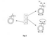
図1は、取り付けピン2を備えたキャスタ1を示している。取り付けピン2は、垂直回転軸3を有し、キャスタ1は当該回転軸周りに旋回可能である。キャスタ1は、一組のホイール4,5を有する。これらのホイールは、水平軸6周りに回転可能である。ホイール4,5の上方には、ブレーキアクティベータ7が設けられている。当該ブレーキアクティベータは、矢印8で示すように、軸9を中心として上下に揺動させることによって、3つの位置のいずれかにセットすることができる。図2に示すように、ブレーキアクティベータが上方位置10(方向ロック位置)にある時は、キャスタ1は1つの方向11にロックされる。すなわち、ホイール4,5は自由に回転可能であるが、取り付けピン2は所望の方向にロックされる。従って、キャスタ1は、面上を方向11に沿って走行可能である。ブレーキアクティベータ7を下方位置12(ブレーキ位置)にセットすると,キャスタ1は完全にロックまたは制動される。すなわち、キャスタ1は、取り付けピン2の垂直軸3周りに旋回不能であり、且つ、ホイール4,5は水平軸6周りに回転不能である。従って、キャスタ1は完全に移動不能である。ブレーキアクティベータ7を中間位置13(ニュートラル位置)にセットすると、キャスタ1は、取り付けピン2の垂直軸3周りに自由に旋回可能となり、且つ、ホイール4,5は水平軸6周りに自由に回転可能となる。 FIG. 1 shows a caster 1 with a mounting pin 2. The mounting pin 2 has a vertical rotation shaft 3, and the caster 1 can pivot around the rotation shaft. The caster 1 has a set of
キャスタ1のブレーキアクティベータ7は、サーボモータアセンブリ14に接続されている。図3に概略で示したように、サーボモータアセンブリ14は、サーボモータ15、印刷回路基板(PCB)16、マイクロプロセッサ17、移動センサー18、及び2つのスイッチ19,20を含む。移動センサー18は、例えば加速度計である。サーボモータ15は、直接、あるいは、ギアなどの伝動装置、またはフォーク21の形態をとるレバーアームを介して間接的に、ブレーキアクティベータ7に接続されている。フォーク21は、サーボモータ15のモータ軸23のレバーアーム22と係合している。モータ軸23が軸24周りに回転することによって、ブレーキアクティベータを、上述した3つの位置、すなわち、方向ロック位置10、ニュートラル位置13、ブレーキ位置12のいずれか1つにセットすることができる。2つのスイッチ19,20は、ブレーキアクティベータ7が上記3つの位置の1つにセットされることよって、ピン25,26を介して作動したり非作動になったりする構成とされている。スイッチ19,20は、マイクロプロセッサ17に接続されており、マイクロプロセッサはスイッチ19,20によって生成された信号を受信できるようになっている。サーボモータアセンブリ14は、密閉型キャビネット27に収容されている。 The
図4は、キャスタ制御システム28の概略図である。当該キャスタ制御システムは、上述した、サーボモータアセンブリ14を備えたキャスタ1のタイプの4つのキャスタ29,30,31,32を備える。キャスタ制御システム28は、医療又は介護用設備具(図6参照)あるいは患者用リフト(図7参照)に取り付けて使用することを意図している。各キャスタ29,30,31,32は、プラグ35を有するコネクタケーブル34(図3参照)を介して、電気ブレーキ制御部33に接続されている。電気ブレーキ制御部33は、電源36及び操作パネル37に接続されており、マイクロプロセッサ38を備える。 FIG. 4 is a schematic diagram of the
キャスタ29,30,31,32のうちの1つを、操作パネル37を用いて又は手動でロック位置12にセットすることによって、4つのキャスタ29,30,31,32のすべてをロック位置12にセットすることができる。前者の場合は、操作パネル37からの信号が電気ブレーキ制御部33に送信され、電気ブレーキ制御部が、サーボモータアセンブリ14を介して、各キャスタ29,30,31,32のブレーキアクティベータ7をロック位置12にセットする。後者の場合は、看護人や病院の職員などのオペレーターが、例えばキャスタ29のブレーキアクティベータ7を押してロック位置12にセットする。このブレーキアクティベータ7の位置変更は、スイッチ19,20によって記録される。この情報は、キャスタ29のサーボモータアセンブリ14のマイクロプロセッサ17によって、電気ブレーキ制御部33に送られる。電気ブレーキ制御部33は、この情報を処理し、残りの3つのキャスタ30,31,32もロック位置12にセットされるよう命令する。 By setting one of the
同様の方法で、キャスタ29,30,31,32のうちの1つを、操作パネル37を用いて又は手動でニュートラル位置13にセットすることによって、4つのキャスタ29,30,31,32のすべてをニュートラル位置13にセットすることができる。 In a similar manner, all of the four
キャスタ制御システム28が医療又は介護用設備具に取り付けられる場合、一対のキャスタ29,30;31,32を方向ロック位置10にセット可能である必要がある。これによって、オペレーターが医療又は介護用設備具を移動させやすくなる。この場合も、操作パネル37を用いて又は手動で、キャスタ29,30,31,32のうち、方向ロック位置にセットすべきキャスタの1つを操作することによって、キャスタ29,30,31,32を操作することができる。後者の場合は、オペレーターが、4つのキャスタ29,30,31,32の1つ、例えばキャスタ29、のブレーキアクティベータ7を押して方向ロック位置にセットする。キャスタ29のブレーキアクティベータ7におけるこの位置変更は、スイッチ19,20によって記録される。この情報は、マイクロプロセッサ17によって処理され、キャスタ29のサーボモータアセンブリ14によって電気ブレーキ制御部33に送られる。電気ブレーキ制御部33は、この情報を処理し、もう一方のキャスタ30も方向ロック位置10にセットされるよう命令する。医療又は介護用設備具を最適に制御するためには、残りの2つのキャスタはニュートラル位置13にセットする。同様の方法で、一方の対のキャスタ31,32を方向ロック位置10にセットし、他方の対のキャスタ29,30をニュートラル位置13にセットすることが可能である。 When the
安全性を高めるため、医療又は介護用設備具に取り付けるキャスタ制御システム28は、所定の時間移動されなかった場合にすべてのキャスタ29,30,31,32をロック位置12にセットする時間遅延ブレーキ機能をさらに備えていてもよい。本発明で用いられるキャスタ1,29,30,31,32は、それぞれが移動センサー18を備えている。これによって、キャスタ制御システム28の信頼性が向上する。キャスタ制御システム28の遅延ブレーキ機能において、すべての移動センサーからのデータを受信し、場合によっては比較することができる。また、電気ブレーキ制御部33は、命令された位置、すなわち所望の位置になったかどうかに関するフィードバックを、各キャスタ29,30,31,32から受信することができる。所望の位置になっていない場合、キャスタ制御システム28は、電気ブレーキ制御部33及び/又操作パネル37を介して、視覚的、聴覚的、または触覚的な警告を発することができる。 In order to increase safety, the
このフィードバックループは、キャスタ1(ひいてはブレーキアクティベータ7)をセットするすべての位置10,12,13について用いることができる。ブレーキアクティベータ7の位置は、サーボモータアセンブリ14のスイッチ19,20を介してマイクロプロセッサ17によって記録される。この位置情報がマイクロプロセッサ17によって処理され、電気ブレーキ制御部33のマイクロプロセッサ38に送信される。ブレーキアクティベータ7、ひいてはキャスタ1が所望の位置になっていない場合は、その情報が、例えば視覚的、聴覚的、または触覚的に、あるいはこれら3つを組み合わせた形で、電気ブレーキ制御部33及び/又は操作パネル37を介して、警告としてオペレーターに与えられる。各キャスタ29,30,31,32のブレーキアクティベータ7の位置情報を操作パネル37上に表示することもできる。 This feedback loop can be used for all
図4に示すように、電気ブレーキ制御部33は、電源36に接続されている。また、電気ブレーキ制御部33は、任意で、ケーブル41をコンセントに差し込んで、交流電源40から電力供給を受けることもできる。キャスタ制御システム28を備えた医療又は介護用設備具を交流電源40につないだまま動かすと、ケーブル41によって、当該設備具付近の人や設備に危険が及ぶ可能性がある。また、ケーブル41がコンセントから引き抜かれると、コンセントにダメージを与え、また、ケーブルのプラグが付近の人や設備に当たる可能性もある。さらに悪い場合には、壁からケーブル41を引き抜くことによって、目に見えないダメージをケーブル41に与えることもある。このダメージは、たとえば、ケーブル41の導線が切れる、あるいは、導線間の絶縁が損なわれるといったものであり、これによって短絡が起こる可能性もある。このため、電気ブレーキ制御部33は、電気ブレーキ制御部33が交流電源40に接続されているかどうかを判断するための電源検知器42を備える。 As shown in FIG. 4, the electric
電気ブレーキ制御部33が交流電源40に接続されていることを電源検知器42が検知し、キャスタ29,30,31,32のうち少なくとも1つの移動センサー18が移動を記録すると、キャスタ制御システム28は、視覚的、聴覚的、または触覚的警告を発する、及び/又は、キャスタ29,30,31,32をブレーキ位置12にセットする。電気ブレーキ制御部33を交流電源40から外すと、医療又は介護用設備具は、警告が出たりブレーキが作動したりすることなく移動させることができるようになる。キャスタ制御システム28は、他の場所に設けられた移動センサーに接続することもできる。この場合には、キャスタ29,30,31,32のサーボモータアセンブリ14は、移動センサーを備える必要はない。したがって、より安価なサーボモータアセンブリ14を用いることができる。 When the
キャスタ制御システム28を備えた医療又は介護用設備具の移動中に、職員が誤ってキャスタ29,30,31,32のうちの1つのブレーキアクティベータ7に当たり、このブレーキアクティベータをブレーキ位置12(図2参照)にセットしてしまうかもしれない。キャスタ制御システム28は、このような場合に、キャスタ29,30,31,32を元の位置、すなわち方向ロック位置10又はニュートラル位置13(図2参照)に即座に戻すように設計することができる。機能的には、これは以下のようにして行われる。キャスタ29,30,31,32のサーボモータアセンブリ14に設けられた移動センサー18の1つまたはそれ以上が、医療又は介護用設備具が移動中であることを記録する。この情報は、各サーボモータアセンブリ14のマイクロプロセッサ17を介して、電気ブレーキ制御部33に継続的に送られる。キャスタ29,30,31,32のうちの1つのブレーキアクティベータ7が、誤ってブレーキ位置12(図2参照)にセットされると、このことが、サーボモータアセンブリ14のスイッチ19,20によって即座に記録され、この情報が、上述したように、電気ブレーキ制御部33に送られる。これに反応して、電気ブレーキ制御部33は、サーボモータアセンブリ14を介して、ブレーキアクティベータ7を元の位置にセットする。この機能を、各サーボモータアセンブリ14に振り分けることもできる。この場合、電気ブレーキ制御部33は、各サーボモータアセンブリ14対して、ブレーキアクティベータ7の現在の位置を維持するように指示する。ブレーキアクティベータ7が別の位置にセットされたことをスイッチ19,20が記録すると、マイクロプロセッサ17は、ブレーキアクティベータ7を元の位置に戻すよう、サーボモータ15に命令する。上記のいずれの場合においても、必ずしもブレーキアクティベータ7が完全に別の位置に切り変わっている必要はなく、単に所望の位置から外れただけでも、上記の機能が作動する。すなわち、このような中間位置もスイッチ19,20によって記録され、電気ブレーキ制御部33及び/又はマイクロプロセッサ17を上述のように動作させる。この場合も、キャスタ制御システム28を、他の場所に設けられた移動センサーに接続することもできる。この場合、キャスタ29,30,31,32のサーボモータアセンブリ14が移動センサーを備える必要はない。したがって、より安価なサーボモータアセンブリ14を用いることができる。 During the movement of the medical or nursing equipment provided with the
図5は、リニアアクチュエータシステム43に内蔵されたキャスタ制御システム28を示す。リニアアクチュエータシステム43は、バッテリ45又は交流電源40から電力供給を受けるコントロールボックス44を備える。リニアアクチュエータシステム43は、複数のリニアアクチュエータ46及び操作パネル47を備え、これらはいずれもコントロールボックス44に接続されている。電気ブレーキ制御部33は、コントロールボックス44に接続されており、当該コントロールボックスによって駆動される。したがって、キャスタ制御システム28は、コントロールボックス44を介して、操作パネル47によって制御される。これと同じ接続ラインを通して、電気ブレーキ制御部33からコントロールボックス44にフィードバックを与えることができる。リニアアクチュエータシステム43においては、コントロールボックス44が主装置として機能し、電気ブレーキ制御部33がスレーブ(従装置)として機能する。図示していないが、リニアアクチュエータシステム43は、追加の操作パネルを備えることもできる。リニアアクチュエータ46は、スラストロッドを有するタイプのものである。このタイプのリニアアクチュエータは、スピンドルナット付きのスピンドルを備える。スピンドルは、伝動装置を介して、可逆式電気モータによって駆動される。スピンドルが駆動されると、電気モータの回転方向に応じて、スピンドルナットが内方又は外方に移動する。リニアアクチュエータは、スピンドル、伝動装置、及び電気モータがハウジングに収容された製品である。ハウジングは、一般的には、モータハウジングと外管とを含んで構成されている。スピンドルナットには内管が固定されている。スピンドルナットがスピンドル上で内方又は外方に移動するのに応じて、内管が、外管に対して内方又は外方に変位する。内管のスピンドルナットとは反対側の端部には、前方取り付け部が設けられている。モータハウジングの外側には、後方取り付け部が設けられている。前方取り付け部及び後方取り付け部は、リニアアクチュエータを調節対象の構造に取り付けるのに用いられる。 FIG. 5 shows the
図6は、図5のリニアアクチュエータシステム43を内蔵する医療用又は介護用ベッド48の概略図である。図示していないが、この医療用又は介護用ベッド48は4個のキャスタ29,30,31,32を有しており、このため、図示した2つのキャスタのそれぞれに2つの参照符号を付している。リニアアクチュエータ46は、ベッドのマットレスを保持している上部フレームを下部機構に対して昇降させるのに用いることができる。リニアアクチュエータ46は、ヘッドレスト、バックレスト、レッグレストを昇降させるためにも用いることができる。 FIG. 6 is a schematic view of a medical or
図7は、図5のリニアアクチュエータシステム43を内蔵する患者用リフト49を示している。この場合、リニアアクチュエータ46を用いてアーム50を上下動させ、これによって患者を昇降させる。 FIG. 7 shows a
Claims (11)
Translated fromJapanese水平軸(6)周りに回転可能な少なくとも1つのホイール(4,5)と、
前記キャスタ(1)が前記取り付けピン(2)の前記垂直軸(3)周りに旋回不能である一方、前記ホイール(4,5)が前記水平軸(6)周りに回転自在である方向ロック位置(10)、又は、
前記ホイール(4,5)が前記水平軸(6)周りに回転不能であり、且つ、前記キャスタ(1)が前記取り付けピン(2)の前記垂直軸周りに旋回不能であるブレーキ位置(12)、又は、
前記キャスタ(1)が前記取り付けピン(2)の前記垂直軸(3)周りに旋回自在であり且つ前記ホイール(4,5)が前記水平軸(6)周りに回転自在であるニュートラル位置(13)に、前記キャスタ(1)をセットするためのブレーキアクティベータ(7)と、を備えるキャスタ(1)であって、
サーボモータ(15)と、印刷回路基板(16)と、マイクロプロセッサ(17)と、少なくとも1つのスイッチ(19,20)とを含むサーボモータアセンブリ(14)をさらに備え、前記サーボモータ(15)は前記ブレーキアクティベータに接続されている、キャスタ(1)。A mounting pin (2) having a vertical rotation axis (3) as a pivot axis of the caster (1);
At least one wheel (4, 5) rotatable around a horizontal axis (6);
Direction lock position in which the caster (1) is not pivotable about the vertical axis (3) of the mounting pin (2) while the wheels (4, 5) are rotatable about the horizontal axis (6) (10) or
Brake position (12) where the wheel (4, 5) is not rotatable about the horizontal axis (6) and the caster (1) is not pivotable about the vertical axis of the mounting pin (2) Or
Neutral position (13) in which the caster (1) is pivotable about the vertical axis (3) of the mounting pin (2) and the wheels (4, 5) are rotatable about the horizontal axis (6). A caster (1) comprising a brake activator (7) for setting the caster (1),
The servo motor (15) further includes a servo motor assembly (14) including a servo motor (15), a printed circuit board (16), a microprocessor (17), and at least one switch (19, 20). Is a caster (1) connected to the brake activator.
前記サーボモータアセンブリ(14)の前記マイクロプロセッサ(17)は、前記キャスタ(1,29,30,31,32)のそれぞれの前記ブレーキアクティベータ(7)の前記位置(10,12,13)の情報を前記電気ブレーキ制御部(3)に送信する、請求項3〜5の少なくとも1つに記載のキャスタ制御システム(28)の操作方法。The microprocessor (17) of the servo motor assembly (14) is connected to the brake activator of each of a plurality of casters (1, 29, 30, 31, 32) via at least one switch (19, 20). Detect the position (10, 12, 13) of (7)
The microprocessor (17) of the servo motor assembly (14) is arranged at the position (10, 12, 13) of the brake activator (7) of each of the casters (1, 29, 30, 31, 32). The method of operating a caster control system (28) according to at least one of claims 3 to 5, wherein information is transmitted to the electric brake control unit (3).
前記キャスタが移動中であり、且つ、前記キャスタ制御システム(28)が前記交流電源(40)に接続されていることを前記電源検知器(42)が検知した場合には、前記電気ブレーキ制御部(33)は、前記各キャスタ(1,29,30,31,32)のブレーキアクティベータ(7)を前記ブレーキ位置(13)にセットする、請求項6に記載のキャスタ制御システム(28)の操作方法。The microprocessor (17) of the servo motor assembly (14) detects whether the caster is moving via the movement sensor (18), and the microprocessor (17) of the servo motor assembly (14). 17) simultaneously detects whether the caster control system (28) is connected to the AC power source (40) via the power detector (42),
When the power detector (42) detects that the caster is moving and the caster control system (28) is connected to the AC power source (40), the electric brake control unit The caster control system (28) according to claim 6, wherein (33) sets the brake activator (7) of each caster (1, 29, 30, 31, 32) to the brake position (13). Method of operation.
Applications Claiming Priority (3)
| Application Number | Priority Date | Filing Date | Title |
|---|---|---|---|
| DKPA201100890 | 2011-11-14 | ||
| DKPA201100890 | 2011-11-14 | ||
| PCT/DK2012/000120WO2013071932A1 (en) | 2011-11-14 | 2012-11-13 | Castor control system |
Publications (2)
| Publication Number | Publication Date |
|---|---|
| JP2014533217Atrue JP2014533217A (en) | 2014-12-11 |
| JP6141297B2 JP6141297B2 (en) | 2017-06-07 |
Family
ID=58720513
Family Applications (1)
| Application Number | Title | Priority Date | Filing Date |
|---|---|---|---|
| JP2014540321AExpired - Fee RelatedJP6141297B2 (en) | 2011-11-14 | 2012-11-13 | Caster control system |
Country Status (8)
| Country | Link |
|---|---|
| US (1) | US9266392B2 (en) |
| EP (1) | EP2780176A1 (en) |
| JP (1) | JP6141297B2 (en) |
| CN (1) | CN103946036B (en) |
| AU (1) | AU2012339264B2 (en) |
| BR (1) | BR112014011642A2 (en) |
| RU (1) | RU2014118735A (en) |
| WO (1) | WO2013071932A1 (en) |
Cited By (6)
| Publication number | Priority date | Publication date | Assignee | Title |
|---|---|---|---|---|
| JP2016538041A (en)* | 2013-11-18 | 2016-12-08 | テンテ・ゲーエムベーハー・ウント・ツェーオー・カーゲー | Controller for roller mounted on moving equipment and method for controlling roller mounted on moving equipment |
| WO2017056348A1 (en)* | 2015-09-29 | 2017-04-06 | 富士フイルム株式会社 | Radiation emitting apparatus |
| JP2017064360A (en)* | 2015-09-29 | 2017-04-06 | 富士フイルム株式会社 | Radiation irradiation equipment |
| JP2018092543A (en)* | 2016-12-07 | 2018-06-14 | パラマウントベッド株式会社 | Alarm device, alarm unit, and portable furniture |
| JP2019503822A (en)* | 2015-12-04 | 2019-02-14 | アルジョ アイピー ホールディング アクチエボラグArjo IP Holding Aktiebolag | Display device |
| JP2020512896A (en)* | 2017-04-06 | 2020-04-30 | セクリスト インダストリーズ インコーポレイテッド | Stretcher system with electrically operated wheels |
Families Citing this family (21)
| Publication number | Priority date | Publication date | Assignee | Title |
|---|---|---|---|---|
| US9393487B2 (en) | 2002-07-27 | 2016-07-19 | Sony Interactive Entertainment Inc. | Method for mapping movements of a hand-held controller to game commands |
| BR112014011642A2 (en)* | 2011-11-14 | 2017-05-02 | Linak As | caster control system |
| GB201212765D0 (en)* | 2012-07-18 | 2012-08-29 | Huntleigh Technology Ltd | Hospital bed sensor system |
| US10004651B2 (en) | 2012-09-18 | 2018-06-26 | Stryker Corporation | Patient support apparatus |
| US20150266342A1 (en)* | 2012-10-19 | 2015-09-24 | Fallshaw Holdings Pty Ltd | Castor direction control |
| AU2013347308B9 (en) | 2012-11-13 | 2017-09-07 | Linak A/S | Castor control system |
| US9969216B2 (en)* | 2015-08-21 | 2018-05-15 | Tome, Inc. | Intelligent caster system with occupancy detection and optional solar panel for use with a furniture component |
| US9944121B2 (en)* | 2015-08-24 | 2018-04-17 | Darcor Limited | Dual end remote swivel-lock for caster carts and carts equipped with same |
| US9788647B2 (en)* | 2015-10-13 | 2017-10-17 | Nishan Joshi | Overbed table |
| US10568792B2 (en) | 2015-10-28 | 2020-02-25 | Stryker Corporation | Systems and methods for facilitating movement of a patient transport apparatus |
| US9862230B2 (en)* | 2015-11-20 | 2018-01-09 | Barbara Dunston | Chair lock system |
| CN105365483B (en)* | 2015-12-23 | 2019-06-25 | 联想(北京)有限公司 | Obstacle detouring castor assembly and wheeled apparatus including the obstacle detouring castor assembly |
| CN106080034B (en)* | 2016-06-14 | 2018-05-15 | 广西大学 | A kind of universal chassis that vertically and horizontally straight line moving is accurately realized with controls connecting rod |
| DE102016121217A1 (en)* | 2016-11-07 | 2018-05-09 | Carl Zeiss Meditec Ag | Rollable ophthalmic device |
| US10864127B1 (en) | 2017-05-09 | 2020-12-15 | Pride Mobility Products Corporation | System and method for correcting steering of a vehicle |
| US10806653B2 (en) | 2017-12-21 | 2020-10-20 | Stryker Corporation | Patient transport apparatus with electro-mechanical braking system |
| JP6737408B1 (en) | 2018-09-21 | 2020-08-05 | 日本精工株式会社 | Drive wheels, carts and equipment |
| CN109045599B (en)* | 2018-10-30 | 2024-06-18 | 广东美的安川服务机器人有限公司 | Caster wheel moving device and rehabilitation training equipment |
| USD926472S1 (en)* | 2019-03-14 | 2021-08-03 | It Luggage Limited | Luggage |
| AU2020418915A1 (en) | 2019-12-30 | 2022-07-07 | Stryker Corporation | Patient transport apparatus with electro-mechanical braking system |
| US20220380126A1 (en)* | 2021-05-26 | 2022-12-01 | Symbotic Llc | Autonomous transport vehicle with steering |
Citations (7)
| Publication number | Priority date | Publication date | Assignee | Title |
|---|---|---|---|---|
| JPH0577604A (en)* | 1991-09-20 | 1993-03-30 | Paramount Bed Co Ltd | Caster interlock operation system for both motor-driven and manual operation |
| WO2001085084A1 (en)* | 2000-05-11 | 2001-11-15 | Hill-Rom Services, Inc. | Motorized traction device for a patient support |
| WO2002055322A1 (en)* | 2001-01-12 | 2002-07-18 | Tente-Rollen Gmbh & Co. Kg | Roller |
| JP2006515995A (en)* | 2002-09-06 | 2006-06-15 | ヒル−ロム サービシーズ,インコーポレイティド | Hospital bed |
| WO2007054037A2 (en)* | 2005-11-10 | 2007-05-18 | Linet Spol. S R.O. | Undercarriage for hospital bed |
| JP2008119452A (en)* | 2006-10-13 | 2008-05-29 | Hill-Rom Services Inc | User interface and control system for powered transport device in patient support apparatus |
| US20080141459A1 (en)* | 2006-10-13 | 2008-06-19 | Hamberg Stephen R | Push handle with rotatable user interface |
Family Cites Families (15)
| Publication number | Priority date | Publication date | Assignee | Title |
|---|---|---|---|---|
| US4080809A (en)* | 1977-06-09 | 1978-03-28 | The Maytag Company | Caster brake control system |
| US5377372A (en) | 1993-03-31 | 1995-01-03 | Hill-Rom Company, Inc. | Hospital bed castor control mechanism |
| DE10105614A1 (en)* | 2001-01-12 | 2002-07-18 | Tente Rollen Gmbh & Co | role |
| US6668965B2 (en) | 2001-05-25 | 2003-12-30 | Russell W. Strong | Dolly wheel steering system for a vehicle |
| US7533742B2 (en)* | 2001-10-26 | 2009-05-19 | Dane Industries, Inc. | Bed transfer system |
| US20070056141A1 (en)* | 2005-09-15 | 2007-03-15 | Sergio Armano | Powered locking caster wheel |
| US8452508B2 (en)* | 2005-11-10 | 2013-05-28 | Linet Spol. S.R.O. | Braking system for patient support |
| US8205297B2 (en) | 2007-06-06 | 2012-06-26 | Fallshaw Holdings Pty Ltd | Swivel castor braking system |
| FI7965U1 (en) | 2008-02-27 | 2008-08-06 | Mannerin Konepaja Ab Oy | Device Wheel |
| DE102009033583B4 (en)* | 2009-07-16 | 2022-01-05 | Gross + Froelich Gmbh & Co. Kg | Roller with braking device |
| US8418786B2 (en)* | 2010-05-06 | 2013-04-16 | Transmotion Medical, Inc. | Selectively powered ambulatory stretcher chair |
| US8424158B2 (en)* | 2010-09-07 | 2013-04-23 | Adrian Steenson | Three-state caster assembly with swivel lock and wheel brake |
| BR112014011642A2 (en)* | 2011-11-14 | 2017-05-02 | Linak As | caster control system |
| US9061547B2 (en)* | 2011-12-23 | 2015-06-23 | Caremed Supply Inc. | Power-operated caster brake mechanism |
| EP2819629B1 (en)* | 2012-03-02 | 2016-12-28 | Stryker Corporation | Patient support |
- 2012
- 2012-11-13BRBR112014011642Apatent/BR112014011642A2/ennot_activeApplication Discontinuation
- 2012-11-13RURU2014118735/11Apatent/RU2014118735A/ennot_activeApplication Discontinuation
- 2012-11-13EPEP12805926.8Apatent/EP2780176A1/ennot_activeWithdrawn
- 2012-11-13USUS14/358,111patent/US9266392B2/ennot_activeExpired - Fee Related
- 2012-11-13CNCN201280055758.4Apatent/CN103946036B/ennot_activeExpired - Fee Related
- 2012-11-13AUAU2012339264Apatent/AU2012339264B2/ennot_activeWithdrawn - After Issue
- 2012-11-13WOPCT/DK2012/000120patent/WO2013071932A1/enactiveApplication Filing
- 2012-11-13JPJP2014540321Apatent/JP6141297B2/ennot_activeExpired - Fee Related
Patent Citations (10)
| Publication number | Priority date | Publication date | Assignee | Title |
|---|---|---|---|---|
| JPH0577604A (en)* | 1991-09-20 | 1993-03-30 | Paramount Bed Co Ltd | Caster interlock operation system for both motor-driven and manual operation |
| WO2001085084A1 (en)* | 2000-05-11 | 2001-11-15 | Hill-Rom Services, Inc. | Motorized traction device for a patient support |
| JP2004515262A (en)* | 2000-05-11 | 2004-05-27 | ヒル−ロム サービシーズ,インコーポレイティド | Automatic traction device for patient support |
| WO2002055322A1 (en)* | 2001-01-12 | 2002-07-18 | Tente-Rollen Gmbh & Co. Kg | Roller |
| JP2004516991A (en)* | 2001-01-12 | 2004-06-10 | テンテ−ローレン ゲーエムベーハー ウント ツェーオー.カーゲー | Caster type rollers driven by electric motor |
| JP2006515995A (en)* | 2002-09-06 | 2006-06-15 | ヒル−ロム サービシーズ,インコーポレイティド | Hospital bed |
| WO2007054037A2 (en)* | 2005-11-10 | 2007-05-18 | Linet Spol. S R.O. | Undercarriage for hospital bed |
| JP2009514620A (en)* | 2005-11-10 | 2009-04-09 | リネット スポル.エスアール.オ. | Hospital bed chassis |
| JP2008119452A (en)* | 2006-10-13 | 2008-05-29 | Hill-Rom Services Inc | User interface and control system for powered transport device in patient support apparatus |
| US20080141459A1 (en)* | 2006-10-13 | 2008-06-19 | Hamberg Stephen R | Push handle with rotatable user interface |
Cited By (8)
| Publication number | Priority date | Publication date | Assignee | Title |
|---|---|---|---|---|
| JP2016538041A (en)* | 2013-11-18 | 2016-12-08 | テンテ・ゲーエムベーハー・ウント・ツェーオー・カーゲー | Controller for roller mounted on moving equipment and method for controlling roller mounted on moving equipment |
| WO2017056348A1 (en)* | 2015-09-29 | 2017-04-06 | 富士フイルム株式会社 | Radiation emitting apparatus |
| JP2017064360A (en)* | 2015-09-29 | 2017-04-06 | 富士フイルム株式会社 | Radiation irradiation equipment |
| US10667772B2 (en) | 2015-09-29 | 2020-06-02 | Fujifilm Corporation | Radiation-irradiation device |
| JP2019503822A (en)* | 2015-12-04 | 2019-02-14 | アルジョ アイピー ホールディング アクチエボラグArjo IP Holding Aktiebolag | Display device |
| US10932969B2 (en) | 2015-12-04 | 2021-03-02 | Arjo Ip Holding Ab | Indicator device |
| JP2018092543A (en)* | 2016-12-07 | 2018-06-14 | パラマウントベッド株式会社 | Alarm device, alarm unit, and portable furniture |
| JP2020512896A (en)* | 2017-04-06 | 2020-04-30 | セクリスト インダストリーズ インコーポレイテッド | Stretcher system with electrically operated wheels |
Also Published As
| Publication number | Publication date |
|---|---|
| US20140324315A1 (en) | 2014-10-30 |
| AU2012339264A1 (en) | 2014-04-24 |
| BR112014011642A2 (en) | 2017-05-02 |
| CN103946036A (en) | 2014-07-23 |
| CN103946036B (en) | 2017-09-29 |
| RU2014118735A (en) | 2015-12-27 |
| US9266392B2 (en) | 2016-02-23 |
| WO2013071932A1 (en) | 2013-05-23 |
| EP2780176A1 (en) | 2014-09-24 |
| AU2012339264B2 (en) | 2017-04-13 |
| JP6141297B2 (en) | 2017-06-07 |
Similar Documents
| Publication | Publication Date | Title |
|---|---|---|
| JP6141297B2 (en) | Caster control system | |
| AU2013347308B2 (en) | Castor control system | |
| US10632033B1 (en) | Bed-based safety protocol control | |
| US11246776B2 (en) | Patient support with improved control | |
| US12048661B2 (en) | Patient transport apparatus with electro-mechanical braking system | |
| EP3087964B1 (en) | Person support apparatus power drive system | |
| US11559450B2 (en) | Patient support apparatus user interfaces | |
| JP2009533201A (en) | System and method for transporting a bed | |
| EP3703074B1 (en) | Patient bed with interface for manual input of its location | |
| US11484451B1 (en) | Patient support apparatus user interfaces | |
| EP2422758A2 (en) | Incline based bed height | |
| US20250279198A1 (en) | Apparatus and method for updating software in a patient support apparatus using a memory toggle | |
| EP4175600A1 (en) | Patient support apparatus | |
| EP3897501B1 (en) | Patient support apparatus with touchscreen | |
| EP2890350B1 (en) | System for propelling hospital bed | |
| AU2023273098A1 (en) | Patient support apparatus having central dual control system of casters |
Legal Events
| Date | Code | Title | Description |
|---|---|---|---|
| A621 | Written request for application examination | Free format text:JAPANESE INTERMEDIATE CODE: A621 Effective date:20150914 | |
| A977 | Report on retrieval | Free format text:JAPANESE INTERMEDIATE CODE: A971007 Effective date:20160729 | |
| A131 | Notification of reasons for refusal | Free format text:JAPANESE INTERMEDIATE CODE: A131 Effective date:20160802 | |
| A601 | Written request for extension of time | Free format text:JAPANESE INTERMEDIATE CODE: A601 Effective date:20161101 | |
| A521 | Request for written amendment filed | Free format text:JAPANESE INTERMEDIATE CODE: A523 Effective date:20161228 | |
| TRDD | Decision of grant or rejection written | ||
| A01 | Written decision to grant a patent or to grant a registration (utility model) | Free format text:JAPANESE INTERMEDIATE CODE: A01 Effective date:20170404 | |
| A61 | First payment of annual fees (during grant procedure) | Free format text:JAPANESE INTERMEDIATE CODE: A61 Effective date:20170502 | |
| R150 | Certificate of patent or registration of utility model | Ref document number:6141297 Country of ref document:JP Free format text:JAPANESE INTERMEDIATE CODE: R150 | |
| LAPS | Cancellation because of no payment of annual fees |