JP2014529307A - Method and apparatus for resewing an articular lip to an acetabulum, including the provision and use of a novel suture anchor system - Google Patents
Method and apparatus for resewing an articular lip to an acetabulum, including the provision and use of a novel suture anchor systemDownload PDFInfo
- Publication number
- JP2014529307A JP2014529307AJP2014519159AJP2014519159AJP2014529307AJP 2014529307 AJP2014529307 AJP 2014529307AJP 2014519159 AJP2014519159 AJP 2014519159AJP 2014519159 AJP2014519159 AJP 2014519159AJP 2014529307 AJP2014529307 AJP 2014529307A
- Authority
- JP
- Japan
- Prior art keywords
- force
- suture
- anchor
- inserter
- input
- Prior art date
- Legal status (The legal status is an assumption and is not a legal conclusion. Google has not performed a legal analysis and makes no representation as to the accuracy of the status listed.)
- Pending
Links
- 238000000034methodMethods0.000titleclaimsdescription52
- 210000000588acetabulumAnatomy0.000titledescription52
- 230000007246mechanismEffects0.000claimsabstractdescription168
- 210000000988bone and boneAnatomy0.000claimsabstractdescription117
- 230000005540biological transmissionEffects0.000claimsabstractdescription23
- 238000012546transferMethods0.000claimsdescription52
- 230000033001locomotionEffects0.000claimsdescription15
- 230000000717retained effectEffects0.000claims5
- 230000001902propagating effectEffects0.000claims3
- 239000013013elastic materialSubstances0.000claims1
- 238000010586diagramMethods0.000description94
- 210000004394hip jointAnatomy0.000description48
- 230000003902lesionEffects0.000description30
- 238000013461designMethods0.000description24
- 238000009958sewingMethods0.000description20
- 210000001519tissueAnatomy0.000description20
- 210000001624hipAnatomy0.000description16
- 239000000463materialSubstances0.000description16
- 210000003041ligamentAnatomy0.000description14
- 210000004872soft tissueAnatomy0.000description13
- 230000006835compressionEffects0.000description10
- 238000007906compressionMethods0.000description10
- 230000008878couplingEffects0.000description9
- 238000010168coupling processMethods0.000description9
- 238000005859coupling reactionMethods0.000description9
- 230000006378damageEffects0.000description8
- 230000008439repair processEffects0.000description8
- 210000000323shoulder jointAnatomy0.000description8
- 210000000689upper legAnatomy0.000description8
- 208000027418Wounds and injuryDiseases0.000description7
- 208000014674injuryDiseases0.000description7
- 210000001503jointAnatomy0.000description7
- 239000007787solidSubstances0.000description7
- 239000004696Poly ether ether ketoneSubstances0.000description6
- JUPQTSLXMOCDHR-UHFFFAOYSA-Nbenzene-1,4-diol;bis(4-fluorophenyl)methanoneChemical compoundOC1=CC=C(O)C=C1.C1=CC(F)=CC=C1C(=O)C1=CC=C(F)C=C1JUPQTSLXMOCDHR-UHFFFAOYSA-N0.000description6
- 229920002530polyetherether ketonePolymers0.000description6
- 229920000642polymerPolymers0.000description6
- 238000001356surgical procedureMethods0.000description6
- 238000013459approachMethods0.000description5
- 206010010356Congenital anomalyDiseases0.000description4
- 208000002193PainDiseases0.000description4
- 210000003127kneeAnatomy0.000description4
- 206010052428WoundDiseases0.000description3
- 230000008901benefitEffects0.000description3
- 210000002436femur neckAnatomy0.000description3
- 230000006870functionEffects0.000description3
- 238000011540hip replacementMethods0.000description3
- 238000003780insertionMethods0.000description3
- 230000037431insertionEffects0.000description3
- 210000000629knee jointAnatomy0.000description3
- 238000002324minimally invasive surgeryMethods0.000description3
- 230000000644propagated effectEffects0.000description3
- 238000011541total hip replacementMethods0.000description3
- 230000008733traumaEffects0.000description3
- 229910000639Spring steelInorganic materials0.000description2
- 239000004699Ultra-high molecular weight polyethyleneSubstances0.000description2
- 210000001188articular cartilageAnatomy0.000description2
- 239000002775capsuleSubstances0.000description2
- 238000010276constructionMethods0.000description2
- 230000006866deteriorationEffects0.000description2
- 238000005553drillingMethods0.000description2
- 230000000694effectsEffects0.000description2
- 230000005713exacerbationEffects0.000description2
- 210000000527greater trochanterAnatomy0.000description2
- 210000002414legAnatomy0.000description2
- 210000000528lesser trochanterAnatomy0.000description2
- 229910052751metalInorganic materials0.000description2
- 239000002184metalSubstances0.000description2
- 238000012986modificationMethods0.000description2
- 230000004048modificationEffects0.000description2
- 230000037361pathwayEffects0.000description2
- 229920001432poly(L-lactide)Polymers0.000description2
- 229920000785ultra high molecular weight polyethylenePolymers0.000description2
- 0C=CC=*C1=CC=C*1=CChemical compoundC=CC=*C1=CC=C*1=C0.000description1
- 208000023803Hip injuryDiseases0.000description1
- 206010060820Joint injuryDiseases0.000description1
- JVTAAEKCZFNVCJ-REOHCLBHSA-NL-lactic acidChemical compoundC[C@H](O)C(O)=OJVTAAEKCZFNVCJ-REOHCLBHSA-N0.000description1
- 239000004698PolyethyleneSubstances0.000description1
- 229920000954PolyglycolidePolymers0.000description1
- 229910000831SteelInorganic materials0.000description1
- RTAQQCXQSZGOHL-UHFFFAOYSA-NTitaniumChemical compound[Ti]RTAQQCXQSZGOHL-UHFFFAOYSA-N0.000description1
- 230000002745absorbentEffects0.000description1
- 239000002250absorbentSubstances0.000description1
- 230000004913activationEffects0.000description1
- 230000002730additional effectEffects0.000description1
- 210000003484anatomyAnatomy0.000description1
- 238000004873anchoringMethods0.000description1
- 206010003246arthritisDiseases0.000description1
- 238000005452bendingMethods0.000description1
- 230000000975bioactive effectEffects0.000description1
- 230000037182bone densityEffects0.000description1
- 210000000845cartilageAnatomy0.000description1
- 239000004568cementSubstances0.000description1
- 230000001010compromised effectEffects0.000description1
- 239000000470constituentSubstances0.000description1
- 230000008602contractionEffects0.000description1
- 229920001577copolymerPolymers0.000description1
- 230000006735deficitEffects0.000description1
- 238000003745diagnosisMethods0.000description1
- 230000026058directional locomotionEffects0.000description1
- 208000037265diseases, disorders, signs and symptomsDiseases0.000description1
- 208000035475disorderDiseases0.000description1
- 210000001981hip boneAnatomy0.000description1
- 208000012285hip painDiseases0.000description1
- 239000000017hydrogelSubstances0.000description1
- 210000001621ilium boneAnatomy0.000description1
- 230000007774longtermEffects0.000description1
- 150000002739metalsChemical class0.000description1
- 210000000944nerve tissueAnatomy0.000description1
- 230000000399orthopedic effectEffects0.000description1
- 238000004806packaging method and processMethods0.000description1
- 230000007170pathologyEffects0.000description1
- 210000004197pelvisAnatomy0.000description1
- 230000000149penetrating effectEffects0.000description1
- 239000004033plasticSubstances0.000description1
- 229920003023plasticPolymers0.000description1
- 229920000747poly(lactic acid)Polymers0.000description1
- 229920002463poly(p-dioxanone) polymerPolymers0.000description1
- 239000000622polydioxanoneSubstances0.000description1
- 229920000728polyesterPolymers0.000description1
- 239000004633polyglycolic acidSubstances0.000description1
- 239000004626polylactic acidSubstances0.000description1
- 230000008569processEffects0.000description1
- 210000003689pubic boneAnatomy0.000description1
- 238000011084recoveryMethods0.000description1
- 238000000926separation methodMethods0.000description1
- 229910001220stainless steelInorganic materials0.000description1
- 239000010935stainless steelSubstances0.000description1
- 238000011272standard treatmentMethods0.000description1
- 239000010959steelSubstances0.000description1
- 239000003356suture materialSubstances0.000description1
- 238000003856thermoformingMethods0.000description1
- 239000010936titaniumSubstances0.000description1
- 229910052719titaniumInorganic materials0.000description1
- 238000012549trainingMethods0.000description1
- 238000009966trimmingMethods0.000description1
- PAPBSGBWRJIAAV-UHFFFAOYSA-Nε-CaprolactoneChemical compoundO=C1CCCCCO1PAPBSGBWRJIAAV-UHFFFAOYSA-N0.000description1
Images


Classifications
- A—HUMAN NECESSITIES
- A61—MEDICAL OR VETERINARY SCIENCE; HYGIENE
- A61B—DIAGNOSIS; SURGERY; IDENTIFICATION
- A61B17/00—Surgical instruments, devices or methods
- A61B17/04—Surgical instruments, devices or methods for suturing wounds; Holders or packages for needles or suture materials
- A61B17/0401—Suture anchors, buttons or pledgets, i.e. means for attaching sutures to bone, cartilage or soft tissue; Instruments for applying or removing suture anchors
- A—HUMAN NECESSITIES
- A61—MEDICAL OR VETERINARY SCIENCE; HYGIENE
- A61B—DIAGNOSIS; SURGERY; IDENTIFICATION
- A61B17/00—Surgical instruments, devices or methods
- A61B17/04—Surgical instruments, devices or methods for suturing wounds; Holders or packages for needles or suture materials
- A61B17/0467—Instruments for cutting sutures
- A—HUMAN NECESSITIES
- A61—MEDICAL OR VETERINARY SCIENCE; HYGIENE
- A61B—DIAGNOSIS; SURGERY; IDENTIFICATION
- A61B90/00—Instruments, implements or accessories specially adapted for surgery or diagnosis and not covered by any of the groups A61B1/00 - A61B50/00, e.g. for luxation treatment or for protecting wound edges
- A61B90/03—Automatic limiting or abutting means, e.g. for safety
- A—HUMAN NECESSITIES
- A61—MEDICAL OR VETERINARY SCIENCE; HYGIENE
- A61B—DIAGNOSIS; SURGERY; IDENTIFICATION
- A61B17/00—Surgical instruments, devices or methods
- A61B17/16—Instruments for performing osteoclasis; Drills or chisels for bones; Trepans
- A61B17/1604—Chisels; Rongeurs; Punches; Stamps
- A—HUMAN NECESSITIES
- A61—MEDICAL OR VETERINARY SCIENCE; HYGIENE
- A61B—DIAGNOSIS; SURGERY; IDENTIFICATION
- A61B17/00—Surgical instruments, devices or methods
- A61B17/16—Instruments for performing osteoclasis; Drills or chisels for bones; Trepans
- A61B17/1662—Instruments for performing osteoclasis; Drills or chisels for bones; Trepans for particular parts of the body
- A61B17/1664—Instruments for performing osteoclasis; Drills or chisels for bones; Trepans for particular parts of the body for the hip
- A61B17/1666—Instruments for performing osteoclasis; Drills or chisels for bones; Trepans for particular parts of the body for the hip for the acetabulum
- A—HUMAN NECESSITIES
- A61—MEDICAL OR VETERINARY SCIENCE; HYGIENE
- A61B—DIAGNOSIS; SURGERY; IDENTIFICATION
- A61B17/00—Surgical instruments, devices or methods
- A61B17/16—Instruments for performing osteoclasis; Drills or chisels for bones; Trepans
- A61B17/17—Guides or aligning means for drills, mills, pins or wires
- A61B17/1739—Guides or aligning means for drills, mills, pins or wires specially adapted for particular parts of the body
- A61B17/1742—Guides or aligning means for drills, mills, pins or wires specially adapted for particular parts of the body for the hip
- A61B17/1746—Guides or aligning means for drills, mills, pins or wires specially adapted for particular parts of the body for the hip for the acetabulum
- A—HUMAN NECESSITIES
- A61—MEDICAL OR VETERINARY SCIENCE; HYGIENE
- A61B—DIAGNOSIS; SURGERY; IDENTIFICATION
- A61B17/00—Surgical instruments, devices or methods
- A61B17/04—Surgical instruments, devices or methods for suturing wounds; Holders or packages for needles or suture materials
- A61B17/0401—Suture anchors, buttons or pledgets, i.e. means for attaching sutures to bone, cartilage or soft tissue; Instruments for applying or removing suture anchors
- A61B2017/0409—Instruments for applying suture anchors
- A—HUMAN NECESSITIES
- A61—MEDICAL OR VETERINARY SCIENCE; HYGIENE
- A61B—DIAGNOSIS; SURGERY; IDENTIFICATION
- A61B17/00—Surgical instruments, devices or methods
- A61B17/04—Surgical instruments, devices or methods for suturing wounds; Holders or packages for needles or suture materials
- A61B17/0401—Suture anchors, buttons or pledgets, i.e. means for attaching sutures to bone, cartilage or soft tissue; Instruments for applying or removing suture anchors
- A61B2017/0412—Suture anchors, buttons or pledgets, i.e. means for attaching sutures to bone, cartilage or soft tissue; Instruments for applying or removing suture anchors having anchoring barbs or pins extending outwardly from suture anchor body
- A—HUMAN NECESSITIES
- A61—MEDICAL OR VETERINARY SCIENCE; HYGIENE
- A61B—DIAGNOSIS; SURGERY; IDENTIFICATION
- A61B17/00—Surgical instruments, devices or methods
- A61B17/04—Surgical instruments, devices or methods for suturing wounds; Holders or packages for needles or suture materials
- A61B17/0401—Suture anchors, buttons or pledgets, i.e. means for attaching sutures to bone, cartilage or soft tissue; Instruments for applying or removing suture anchors
- A61B2017/0414—Suture anchors, buttons or pledgets, i.e. means for attaching sutures to bone, cartilage or soft tissue; Instruments for applying or removing suture anchors having a suture-receiving opening, e.g. lateral opening
- A—HUMAN NECESSITIES
- A61—MEDICAL OR VETERINARY SCIENCE; HYGIENE
- A61B—DIAGNOSIS; SURGERY; IDENTIFICATION
- A61B17/00—Surgical instruments, devices or methods
- A61B17/04—Surgical instruments, devices or methods for suturing wounds; Holders or packages for needles or suture materials
- A61B17/0401—Suture anchors, buttons or pledgets, i.e. means for attaching sutures to bone, cartilage or soft tissue; Instruments for applying or removing suture anchors
- A61B2017/042—Suture anchors, buttons or pledgets, i.e. means for attaching sutures to bone, cartilage or soft tissue; Instruments for applying or removing suture anchors plastically deformed during insertion
- A61B2017/0422—Suture anchors, buttons or pledgets, i.e. means for attaching sutures to bone, cartilage or soft tissue; Instruments for applying or removing suture anchors plastically deformed during insertion by insertion of a separate member into the body of the anchor
- A61B2017/0424—Suture anchors, buttons or pledgets, i.e. means for attaching sutures to bone, cartilage or soft tissue; Instruments for applying or removing suture anchors plastically deformed during insertion by insertion of a separate member into the body of the anchor the separate member staying in the anchor after placement
- A—HUMAN NECESSITIES
- A61—MEDICAL OR VETERINARY SCIENCE; HYGIENE
- A61B—DIAGNOSIS; SURGERY; IDENTIFICATION
- A61B17/00—Surgical instruments, devices or methods
- A61B17/04—Surgical instruments, devices or methods for suturing wounds; Holders or packages for needles or suture materials
- A61B17/0401—Suture anchors, buttons or pledgets, i.e. means for attaching sutures to bone, cartilage or soft tissue; Instruments for applying or removing suture anchors
- A61B2017/0446—Means for attaching and blocking the suture in the suture anchor
- A61B2017/0458—Longitudinal through hole, e.g. suture blocked by a distal suture knot
- A—HUMAN NECESSITIES
- A61—MEDICAL OR VETERINARY SCIENCE; HYGIENE
- A61B—DIAGNOSIS; SURGERY; IDENTIFICATION
- A61B17/00—Surgical instruments, devices or methods
- A61B17/04—Surgical instruments, devices or methods for suturing wounds; Holders or packages for needles or suture materials
- A61B2017/0496—Surgical instruments, devices or methods for suturing wounds; Holders or packages for needles or suture materials for tensioning sutures
- A—HUMAN NECESSITIES
- A61—MEDICAL OR VETERINARY SCIENCE; HYGIENE
- A61B—DIAGNOSIS; SURGERY; IDENTIFICATION
- A61B90/00—Instruments, implements or accessories specially adapted for surgery or diagnosis and not covered by any of the groups A61B1/00 - A61B50/00, e.g. for luxation treatment or for protecting wound edges
- A61B90/03—Automatic limiting or abutting means, e.g. for safety
- A61B2090/037—Automatic limiting or abutting means, e.g. for safety with a frangible part, e.g. by reduced diameter
Landscapes
- Health & Medical Sciences (AREA)
- Life Sciences & Earth Sciences (AREA)
- Surgery (AREA)
- Molecular Biology (AREA)
- General Health & Medical Sciences (AREA)
- Biomedical Technology (AREA)
- Heart & Thoracic Surgery (AREA)
- Medical Informatics (AREA)
- Nuclear Medicine, Radiotherapy & Molecular Imaging (AREA)
- Animal Behavior & Ethology (AREA)
- Engineering & Computer Science (AREA)
- Public Health (AREA)
- Veterinary Medicine (AREA)
- Rheumatology (AREA)
- Oral & Maxillofacial Surgery (AREA)
- Pathology (AREA)
- Prostheses (AREA)
- Surgical Instruments (AREA)
Abstract
Translated fromJapaneseDescription
Translated fromJapanese発明者
Andrew Lantz
J. Brook Burley
Jeremy Graul
James Flom
係属中の先行特許出願の参照Inventor Andrew Lantz
J. et al. Brook Burley
Jeremy Graul
James Fromm
Reference to pending prior patent applications
本特許出願は、
(i)2010年07月19日に出願された、Chris Pamichevらの「METHOD AND APPARATUS FOR RE−ATTACHING THE LABRUM TO THE ACETABULUM,INCLUDING THE PROVISION AND USE OF A NOVEL SUTURE ANCHOR SYSTEM」という名称の係属中の先行する米国特許出願第12/839,246号(代理人整理番号FIAN−4655)の一部継続出願であり、米国特許出願第12/839,246号は、(1)2009年07月17日に出願された、Chris Pamichevらの「METHOD AND APPARATUS FOR RE−SECURING THE LABRUM TO THE ACETABULUM,INCLUDING THE PROVISION AND USE OF A NOVEL NANO TACK SYSTEM」という名称の先行する米国仮特許出願第61/271,205号(代理人整理番号FIAN−46 PROV)および(2)2010年04月22日に出願された、Chris Pamichevらの「METHOD AND APPARATUS FOR RE−SECURING THE LABRUM TO THE ACETABULUM,INCLUDING THE PROVISION AND USE OF A NOVEL SUTURE ANCHOR SYSTEM」という名称の係属中の先行する米国仮特許出願第61/326,709号(代理人整理番号FIAN−55 PROV)の利益を主張するものであり、
(ii)2011年1月13日に出願された、Pivot Medical,Inc.およびChris Pamichevらの「METHOD AND APPARATUS FOR RE−ATTACHING THE LABRUM TO THE ACETABULUM,INCLUDING THE PROVISION AND USE OF A NOVEL SUTURE ANCHOR SYSTEM」という名称の係属中の先行する国際(PCT)特許出願第PCT/US2011/021173号(代理人整理番号FIAN−70 PCT)の一部継続出願であり、
(iii)2011年06月29日に出願された、Andrew Lantzらの「FORCE−LIMITING (FORCE−CONTROLLING) DELIVERY MECHANISMS FOR THE CONTROLLED DELIVERY OF THE SUTURE ANCHOR」という名称の係属中の先行する米国仮特許出願第61/502,621号(代理人整理番号 FIAN−74A PROV)の利益を主張するものである。This patent application
(I) "METHOD AND APPARATUS FOR RE-ATTACHING THE LABRUM TO THE ACETABULUUM, INCLUDING THE PROVION AND USE OF USE OF USE OF THE" filed on Jul. 19, 2010 by Chris Pamichev et al. US Patent Application No. 12 / 839,246 (Attorney Docket No. FIAN-4655) is a continuation-in-part application, and US Patent Application No. 12 / 839,246 is (1) July 17, 2009 “METHOD AND APPARATUS FOR RE-SECURING THE LABRUM THE THE ACETABULUM” of Chris Pamichev et al. US Provisional Patent Application Nos. 61 / 271,205 (Attorney Docket Number FIAN-46 PROV) named INCLUDING THE PROVISION AND USE OF A NOVEL NANO TACK SYSTEM, and (2) filed on April 22, 2010. US Patent No. 32, entitled "METHOD AND APPARATUS FOR RE-SECURING THE LABRUM TO THE ACETABULUUM, INCLUDING THE PROVISION AND USE OF A NOVEL SOURT" by Chris Pamichev et al. 709 (Attorney Docket Number FIAN-55 PROV)
(Ii) Pivot Medical, Inc., filed on January 13, 2011. And Chris Pamichev et al., "METHOD AND APPARATUS FOR RE-ATTACHING THE LABRUM TO THE ACETABULUM, INCLUDING THE PROVISION AND USE OF A NOVEL STURT No.021173 (Attorney Docket Number FIAN-70 PCT)
(Iii) "French-Controlling (Derived-Mechanism) FOR THE CONTROLLED DELIVERY OF THE SURURE" in the title of Andrew Lantz et al., Filed on June 29, 2011. No. 61 / 502,621 (Attorney Docket Number FIAN-74A PROV) is claimed.
上記の5つの特許出願は、参照により本明細書に組み込まれる。 The above five patent applications are incorporated herein by reference.
本発明は、一般に、外科的な方法および装置に関し、より詳細には、股関節を治療するための外科的な方法および装置に関する。 The present invention relates generally to surgical methods and devices, and more particularly to surgical methods and devices for treating a hip joint.
股関節の概要
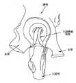
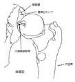
股関節は、脚を胴に移動可能に接続する球関節である。股関節は、たとえば、屈曲および伸展、外転および内転、内旋および外旋などの広範なさまざまな運動が可能である。図1A、図1B、図1C、および図1Dを参照されたい。Hip Joint Overview The hip joint is a ball joint that movably connects legs to the torso. The hip joint is capable of a wide variety of movements such as flexion and extension, abduction and adduction, internal rotation and external rotation, for example. See FIGS. 1A, 1B, 1C, and 1D.
肩関節は例外とも考えられるが、股関節はおそらく身体で最も可動性の高い関節である。重要なことに、肩関節とは異なり、股関節は1日のほとんどの間、静止状態(たとえば、起立および着座)と動作状態(たとえば、歩行およびランニング)の両方でかなりの体重負荷を支える。 The shoulder joint is considered an exception, but the hip joint is probably the most mobile joint in the body. Importantly, unlike the shoulder joint, the hip joint carries a significant weight load both stationary (eg standing and sitting) and operating (eg walking and running) for most of the day.
股関節はいくつかの異なる病変に罹患しやすい。これらの病変には、先天性の原因と、傷害関連の原因の両方があり得る。病変は、発症時にかなり重症(substantial)である場合もあれば、発症時は軽微であるが、治療しないまま放置すると、時間が経つにつれて悪化する場合もある。より具体的には、多くの場合、既存の病変は、股関節の動力学的な性質(dynamic nature)と、かなりの体重負荷が股関節にかかることによって増悪し得る。 The hip joint is susceptible to several different lesions. These lesions can have both congenital causes and injury-related causes. Lesions may be fairly substantive at onset or minor at onset, but may worsen over time if left untreated. More specifically, in many cases, existing lesions can be exacerbated by the dynamic nature of the hip joint and the significant weight load on the hip joint.
病変は、最初またはその後に、患者の快適さおよびライフスタイルに大きく干渉する場合がある。場合によっては、病変が、人工股関節部分置換術または人工股関節全置換術を必要とするほど重症なことがある。人工股関節部分置換術または人工股関節全置換術を実施せずに股関節の病変を治療するためのいくつかの手技が開発されてきたが、これらの手技には股関節の治療に関連する重大な問題があるために、通常、その適応範囲に限界がある。 Lesions can significantly interfere with patient comfort and lifestyle either initially or thereafter. In some cases, the lesion may be severe enough to require partial hip replacement or total hip replacement. Several procedures have been developed to treat hip lesions without performing partial hip replacement or total hip replacement, but these procedures have significant problems related to hip treatment. For this reason, there is usually a limit to the range of application.
股関節の種々の病変、またそれらの治療に関連する現在の限界については、股関節の解剖学的構造をより徹底的に理解することによって、理解を深めることができる。
股関節の解剖学的構造
股関節は、脚と胴の接合部に形成される。より具体的には、ここで図2を参照すると、大腿骨頭は股関節の寛骨臼カップ(acetabular cup)に収納され、複数の靱帯および他の軟部組織は、関節につながれている状態で骨を保持する役割を果たす。The various lesions of the hip joint, and the current limitations associated with their treatment, can be better understood by a more thorough understanding of the hip anatomy.
Hip Anatomy The hip joint is formed at the junction of the leg and torso. More specifically, referring now to FIG. 2, the femoral head is housed in a hip acetabular cup, and a plurality of ligaments and other soft tissues are attached to the joint while the bone is attached. Play a role to hold.
より具体的には、次に図3を参照すると、大腿骨は、通常、細長い骨体(body)がその上端において、ある角度をなす骨頚内で終わり、骨頚は半球状の骨頭(「骨球」と呼ばれることもある)を支持することを特徴とする。図3および図4に示されるように、大転子として知られる大きな突出部が、大腿骨頚に隣接する細長い骨体から外側および後方に突き出ている。小転子として知られるやや小さな第2の突出部は、骨頚に隣接する細長い骨体から内側および後方に突き出ている。転子間稜(図3および図4)は、大転子と小転子の間を大腿骨の辺縁に沿って延びる。 More specifically, referring now to FIG. 3, the femur usually ends within an angled neck at the upper end of the elongated body, and the neck is a hemispherical head (“ It is also characterized by supporting "sometimes called a bone ball". As shown in FIGS. 3 and 4, a large protrusion known as the greater trochanter protrudes outward and posterior from the elongated bone adjacent to the femoral neck. A slightly smaller second protrusion, known as the lesser trochanter, protrudes inward and backward from the elongated bone body adjacent to the bone neck. The intertrochanteric ridge (FIGS. 3 and 4) extends along the margin of the femur between the greater trochanter and the lesser trochanter.
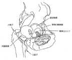
次に図5を参照すると、股関節ソケット(hip socket)は、3つの構成骨、すなわち腸骨、坐骨、および恥骨から構成されている。これらの3つの骨は、集合的に寛骨臼カップを形成するために互いに協調する(これらは、一般的には25歳位までに骨化して1つの「寛骨」構造を形成する)。寛骨臼カップは、大腿骨の骨頭を受ける。 Referring now to FIG. 5, the hip socket is composed of three constituent bones: the iliac bone, the ischial bone, and the pubic bone. These three bones cooperate with each other to collectively form an acetabular cup (they generally ossify by about 25 years of age to form a single “acetabular” structure). The acetabular cup receives the femoral head.
大腿骨頭と寛骨臼カップは両方とも、その下にある骨を保護し運動を容易にする関節軟骨の層で被覆される。図6を参照されたい。 Both the femoral head and the acetabular cup are coated with a layer of articular cartilage that protects the underlying bone and facilitates movement. See FIG.
種々の靱帯および軟部組織は、寛骨臼カップ内の所定の位置で大腿骨球を保持する役割を果たす。より具体的には、次に図7および図8を参照すると、大腿骨頭靱帯(ligamentum teres)が大腿骨球と寛骨臼カップの基部との間に延びる。図8および図9に示されるように、関節唇が寛骨臼カップの辺縁にある。関節唇は寛骨臼カップの深さを増す役割を果たし、大腿骨球と寛骨臼カップ縁の間の吸引封止(suction seal)を効果的に確立して、それにより寛骨臼カップ内に大腿骨頭を保持するのに役立つ。前述の内容に加えて、ここで図10を参照すると、線維被膜(fibrous capsule)が大腿骨頚と寛骨臼カップ縁の間に延び、骨体の残りの部分から股関節の球部材(ball−and−socket member)を効果的に密閉する。前述の構造(すなわち、大腿骨頭靱帯、関節唇、および線維被膜)は、大腿骨と股関節ソケットの辺縁との間に延びる1組の3つの主要靱帯(すなわち、腸骨大腿靱帯、坐骨大腿靱帯、および恥骨大腿靱帯)によって包み込まれ、補強される。たとえば、腸骨大腿靱帯を示す図11および図12を参照されたい。図11は前面図であり、図12は後面図である。
股関節の諸病変
前述のように、股関節はいくつかの異なる病変に罹患しやすい。これらの病変には、先天性の原因と、傷害関連の原因の両方があり得る。Various ligaments and soft tissue serve to hold the femoral ball in place within the acetabular cup. More specifically, referring now to FIGS. 7 and 8, a ligamentum teres extends between the femoral ball and the base of the acetabular cup. As shown in FIGS. 8 and 9, the articular lip is at the edge of the acetabular cup. The articular lip serves to increase the depth of the acetabular cup, effectively establishing a suction seal between the femoral ball and the acetabular cup edge, thereby allowing the acetabular cup to Helps to hold the femoral head. In addition to the foregoing, referring now to FIG. 10, a fibrous capsule extends between the femoral neck and the acetabular cup rim, and from the rest of the bone body the ball of the hip joint (ball- and-socket member) is effectively sealed. The aforementioned structure (i.e., femoral head ligament, joint lip, and fibrous capsule) is a set of three major ligaments (i.e., iliac femoral ligament, sciatic femoral ligament) that extend between the femur and the margin of the hip socket , And pubic femoral ligament). See, for example, FIGS. 11 and 12, which show the iliac femoral ligament. FIG. 11 is a front view, and FIG. 12 is a rear view.
Hip joint lesions As mentioned above, the hip joint is susceptible to several different lesions. These lesions can have both congenital causes and injury-related causes.
限定ではなく、例を挙げると、股関節の先天性病変の1つの重要なタイプは、大腿骨頚と寛骨臼カップ縁の間のインピンジメントに関連するものである。次に図13を参照すると、このインピンジメントは、大腿骨の幾何学的形状に凹凸があるために生じる場合がある。このタイプのインピンジメントは、カム型の大腿寛骨臼インピンジメント(すなわち、カム型FAI)と呼ばれることもある。また、次に図14を参照すると、寛骨臼カップの幾何学的形状に凹凸があるためにインピンジメントが生じる場合がある。この後者のタイプのインピンジメントは、ピンサー型の大腿寛骨臼インピンジメント(すなわち、ピンサー型FAI)と呼ばれることもある。インピンジメントにより、可動域の減少、かなりの疼痛、および場合によっては、股関節の著しい悪化が生じることがある。 By way of example and not limitation, one important type of congenital lesion of the hip joint is associated with impingement between the femoral neck and the acetabular cup edge. Referring now to FIG. 13, this impingement may occur due to irregularities in the femur geometry. This type of impingement is sometimes referred to as a cam-type femoral acetabular impingement (ie, cam-type FAI). Also referring now to FIG. 14, impingement may occur due to irregularities in the acetabular cup geometry. This latter type of impingement is sometimes referred to as a pincer-type femoral acetabular impingement (ie, a pincer-type FAI). Impingement can result in reduced range of motion, significant pain, and in some cases, significant deterioration of the hip joint.
限定ではなく、さらなる例を挙げると、股関節の先天性病変の別の重要なタイプは、骨球の関節面および/または寛骨臼カップの関節面の障害に関連する。このタイプの障害は、発症時はかなり小さいが、通常、股関節の動力学的な性質のために、さらに股関節には体重がかかるという性質があるために、時間が経つにつれて大きくなることが多い。関節の障害により、かなりの疼痛が生じ、関節炎の病状が誘発および/または増悪され、場合によっては、股関節が著しく悪化することがある。 By way of further example and not limitation, another important type of congenital lesion of the hip joint is associated with impairment of the articular surface of the bone ball and / or the articular surface of the acetabular cup. This type of disorder is fairly small at the time of onset, but often grows over time due to the dynamic nature of the hip joint and the fact that the hip joint is weight intensive. Joint damage can cause considerable pain, induce and / or exacerbate the pathology of arthritis, and in some cases, the hip joint can be significantly worsened.
限定ではなく、さらなる例を挙げると、股関節の傷害関連病変の1つの重要なタイプは、関節唇の外傷に関連するものである。より具体的には、多くの場合、事故またはスポーツ関連の傷害により、関節唇が寛骨臼カップ縁から剥離することがあり、一般的には、関節唇の主要部(the body of the labrum)が断裂する。図15を参照されたい。これらのタイプの傷害は、患者にとって非常に苦痛を伴う場合があり、治療しないまま放置すると、股関節の著しい悪化をきたすことがある。
早期の最小侵襲処置を使用する関節の病変の治療に関する一般的な動向
整形外科における現在の動向は、最小侵襲技術を使用して関節の病変を治療することである。このような最小侵襲の「鍵孔」手術には通常、従来の「開創直視下」手術(“open” surgery)に比べて、組織の創傷が少ない、患者の疼痛が少ない、回復時間が短縮されるなどを含む多数の利点がある。By way of further example and not limitation, one important type of hip injury related lesion is that associated with joint lip trauma. More specifically, in many cases, accidents or sports-related injuries may cause the joint lips to detach from the acetabular cup rim, generally the body of the labrum. Tears. See FIG. These types of injuries can be very painful for the patient and can cause significant deterioration of the hip joint if left untreated.
General Trends for Treatment of Joint Lesions Using Early Minimally Invasive Procedures The current trend in orthopedics is to treat joint lesions using minimally invasive techniques. Such minimally invasive “keyhole” surgery typically has fewer tissue wounds, less patient pain, and less recovery time than conventional “open surgery” surgery (“open” surgery). There are a number of advantages including
限定ではなく、例を挙げると、肩関節の内部への大きな切開を必要としない最小侵襲の「鍵孔」技術を使用して肩関節の靱帯を再縫着させることは一般的である。限定ではなく、さらなる例を挙げると、最小侵襲技術を使用して、損傷した膝関節半月板軟骨を修復することおよび/または裂傷した膝関節ACL靱帯を置換することは一般的である。 By way of example and not limitation, it is common to resew the ligament of the shoulder joint using a minimally invasive “keyhole” technique that does not require a large incision into the interior of the shoulder joint. By way of example and not limitation, it is common to use minimally invasive techniques to repair damaged knee meniscal cartilage and / or replace a torn knee ACL ligament.
このような最小侵襲法では、外科医が新たな訓練を行う必要がある場合があるが、このような手技には通常、患者にとってかなりの利点があり、現在では、多くの肩関節および膝関節の病変に対する標準治療となっている。 Such minimally invasive techniques may require surgeons to perform additional training, but such procedures usually have significant benefits for the patient and are now available for many shoulder and knee joints. Standard treatment for lesions.
前述の内容に加えて、肩関節および膝関節の病変を治療するための最小侵襲法の固有の利点および広範な有効性を鑑み、現在の動向は、できる限り早く患者の疼痛に対処するように、および病変そのものの増悪を最小限にするように、病変の過程(lifecycle)のもっと早期にこのような治療を提供することである。これは、患者が侵襲的手術に伴うかなりの創傷を負わずにすむように手術手技をできる限り長く遅らせることが通常指示されていた従来の外科の慣行とは大きく異なっている。
股関節の病変の治療
残念なことに、股関節の病変の最小侵襲治療は、肩関節および膝関節の病変の最小侵襲治療に大きく後れを取っている。この原因は、通常、(i)股関節自体の幾何学的形状の制約、ならびに(ii)股関節で一般的に対象としなければならない病変の性質および位置である。In addition to the foregoing, in light of the inherent benefits and broad effectiveness of minimally invasive methods for treating shoulder and knee lesions, current trends are to address patient pain as soon as possible And to provide such treatment earlier in the course of the lesion, so as to minimize the exacerbation of the lesion itself. This is in sharp contrast to conventional surgical practices that were usually directed to delay the surgical procedure as long as possible so that the patient does not suffer the significant wounds associated with invasive surgery.
Treatment of Hip Lesions Unfortunately, minimally invasive treatment of hip lesions lags far behind minimally invasive treatment of shoulder and knee joint lesions. This is usually due to (i) the geometric constraints of the hip joint itself, and (ii) the nature and location of the lesions that must generally be addressed at the hip joint.
より具体的には、股関節は、関節自体の領域内で操作する空間が比較的小さいという意味で「堅い」関節であると通常考えられている。これは、(少なくとも股関節と比べて)比較的「空間が大きい」関節であると通常考えられる肩関節および膝関節と大きく異なっている。その結果、外科医が股関節で最小侵襲手技を実施することは比較的困難である。 More specifically, hip joints are usually considered to be “hard” joints in the sense that the space to operate within the area of the joint itself is relatively small. This is very different from the shoulder and knee joints, which are usually considered relatively “large” joints (at least compared to the hip joint). As a result, it is relatively difficult for a surgeon to perform a minimally invasive procedure at the hip joint.
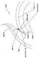
そのうえ、股関節の内部に進入する経路(すなわち、隣接する複数の骨および/または繊細な神経組織の間に存在する自然の経路)は、通常、股関節では肩関節または膝関節の経路よりもはるかに限定されている。このようにアクセスに制限があることによって、股関節の最小侵襲手技を効果的に実施することは事実上さらに難しくなる。 Moreover, the pathways that enter the interior of the hip joint (ie, the natural pathways that exist between adjacent bones and / or delicate nerve tissue) are typically much more common in the hip than in the shoulder or knee. Limited. This limited access makes it practically more difficult to effectively perform minimally invasive hip joint procedures.
前述の内容に加えて、股関節の病変の性質および位置も、股関節で最小侵襲手技を実施することを困難にする。限定ではなく、例を挙げると、典型的な股関節の関節唇の剥離を考えてみよう。この状況では、器具は通常、組織に対する器具の角度からずれた進入角を使用して関節腔の中に導入される。これにより、たとえば、骨の穿孔は、進入角が組織に対する器具の角度と事実上一致する場合と比べて、著しく困難になる。肩関節では、進入角が組織に対する器具の角度と事実上一致することが頻繁である。そのうえ、股関節内の作業空間は、一般的には極めて制限されており、進入角が組織に対する器具の角度と一致しない場合、修復ははるかに困難になる。 In addition to the foregoing, the nature and location of hip joint lesions also makes it difficult to perform minimally invasive procedures at the hip joint. For example and not limitation, consider a typical hip lip detachment. In this situation, the instrument is typically introduced into the joint cavity using an entry angle that is offset from the angle of the instrument with respect to the tissue. This makes, for example, bone drilling significantly more difficult than when the angle of entry is substantially coincident with the angle of the instrument relative to the tissue. In shoulder joints, the angle of entry often coincides with the instrument angle relative to the tissue. Moreover, the working space within the hip joint is generally very limited, and repair is much more difficult if the angle of entry does not match the angle of the instrument relative to the tissue.
前述の内容により、股関節の最小侵襲手技の実施は、今なお比較的困難であり、実際には比較的まれである。したがって、一般的に、患者は、関節面再建(resurfacing)術または人工股関節部分置換術または人工股関節全置換術が回避できなくなるまで股関節の疼痛をできる限り長くやり過ごすことを強いられる。その場合、これらの手技は、通常、侵襲性の高い開創直視下手技として実施され、侵襲性の高い開創直視下手技に関連するすべての欠点を伴う。 Due to the foregoing, performing minimally invasive hip joint procedures is still relatively difficult and in practice relatively rare. Thus, in general, patients are forced to spend as much hip pain as possible until resurfacing or partial hip replacement or total hip replacement cannot be avoided. In that case, these procedures are usually performed as highly invasive retractable direct view procedures, with all the drawbacks associated with highly invasive retractable direct view procedures.
その結果、一般に、股関節の病変を治療するための方法および装置の改善が緊急に必要である。
股関節の関節唇の再縫着
前述のように、股関節鏡は、種々の股関節の病変の診断および治療において、ますます一般的になっている。しかし、股関節の解剖学的構造および股関節に関連する病変により、股関節鏡は現在、選択された病変のみにとって実用的であり、その場合でも、股関節鏡の成功は一般に限られている。As a result, there is generally an urgent need for improved methods and devices for treating hip lesions.
Re-sewing hip joint lips As mentioned above, hip arthroscopy is becoming increasingly common in the diagnosis and treatment of various hip lesions. However, due to the anatomy of the hip joint and the lesions associated with the hip joint, the hip arthroscope is currently practical only for the selected lesion, and even then, the success of the hip arthroscope is generally limited.
関節鏡により試行されることがある1つの手技は、断裂および/または剥離した関節唇の修復に関する。この手技は、(i)関節唇は損傷しているが、依然として修復および/または再縫着が可能であるのに十分なほど健常で損なわれていないとき、および(ii)(たとえば、寛骨臼縁のトリミングがpincer−type FAIなどの病変を治療することを可能にするように)関節唇が故意に剥離されており、その後で再縫着する必要があるとき、試行されることがある。たとえば、図16と図17を参照されたい。図16は、その基部が寛骨臼にしっかりと付着した正常な関節唇を示し、図17は、寛骨臼から剥離された関節唇の一部分(この場合、先端)を示す。この点に関して、試験から、関節唇が修復された患者は関節唇が除去された患者より良好な長期転帰を有する傾向があることが示されているために、一般には関節唇の除去ではなく関節唇の修復が望ましいことも理解されたい。 One procedure that may be attempted with an arthroscope involves the repair of a teared and / or detached joint lip. This procedure is used when (i) the joint lip is damaged but still healthy and intact enough to be repaired and / or resewn, and (ii) (eg, hipbone) May be attempted when the articular lip is deliberately peeled and then needs to be re-sewn (to allow acetabular trimming to treat lesions such as pincer-type FAI) . See, for example, FIG. 16 and FIG. FIG. 16 shows a normal joint lip with its base firmly attached to the acetabulum, and FIG. 17 shows a portion of the joint lip (in this case, the tip) detached from the acetabulum. In this regard, studies have shown that joint lip repair patients tend to have better long-term outcomes than patients with joint lip removal, so joints are generally not joint lip removal. It should also be understood that lip repair is desirable.
残念なことに、関節唇を関節鏡により修復する(たとえば、再縫着する)ための現在の方法および装置には、やや問題がある。本発明は、関節唇修復のための現在の手法を改善することを意図するものである。 Unfortunately, current methods and devices for arthroscopic repair of articular lips (eg, resewing) are somewhat problematic. The present invention is intended to improve current approaches for joint lip repair.
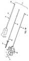
より具体的には、関節唇を関節鏡により修復するための現在の手法では、一般的に、本来は靱帯の骨への再縫着に使用するように設計された装置を使用する。たとえば、このような1つの手法では、そこから延びる2つの縫合糸を備えたスクリュータイプの骨アンカーを利用し、寛骨臼内の関節唇再縫着部位より上で骨アンカーを展開することを含む。縫合糸のうちの第1の縫合糸を、剥離した関節唇を通過して、または別法として、剥離した関節唇の周囲に、通す。次に、関節唇を寛骨臼縁に対して支持するように、第1の縫合糸を第2の縫合糸に結び付ける。図18を参照されたい。 More specifically, current approaches for arthroscopic repair of articular lips generally use devices that were originally designed for use in resewing ligament bones. For example, one such technique involves utilizing a screw-type bone anchor with two sutures extending therefrom to deploy the bone anchor above the joint lip re-sewing site in the acetabulum. Including. A first of the sutures is passed through the peeled joint lips or alternatively around the peeled joint lips. The first suture is then tied to the second suture so as to support the articular lip against the acetabular margin. See FIG.
残念なことに、上記で説明した種類の骨アンカーは、従来、靱帯を骨に再縫着するために使用され、その結果、通常は靱帯再建に関連するかなりの引き抜き力を伝導する必要があるので、比較的大型の傾向がある。しかし、この大型アンカーのサイズは、一般に、関節唇再縫着にとって不必要である。というのは、関節唇は、かなりの引き抜き力にさらされず、大型アンカーのサイズによって、一般的に、患者への不必要な外傷が生じるからである。 Unfortunately, bone anchors of the type described above are traditionally used to resewn the ligament to the bone, so that it is necessary to conduct significant withdrawal forces normally associated with ligament reconstruction. So it tends to be relatively large. However, the size of this large anchor is generally unnecessary for joint lip re-sewing. This is because the articular lips are not exposed to significant withdrawal forces, and the size of the large anchor generally causes unnecessary trauma to the patient.
そのうえ、従来の骨アンカーのサイズが大型であることは、アンカーを関節唇再縫着に使用するときに問題になることがある。というのは、骨アンカーは、一般に、しっかりと係留する(anchor)のにかなりの骨量を必要とし、このような大きな骨量は、一般に、寛骨臼蓋上方のかなりの距離離れたところでしか可能でないからである。さらに、骨アンカーのサイズが大型であることによって、一般に、骨アンカーの遠位先端が意図せずに寛骨臼蓋を通り抜けることなく関節の摺動面と接触することを確実にするために、骨アンカーを寛骨臼蓋上方のかなりの距離離れたところに設定することが必要となる。しかし、寛骨臼蓋の中の深いところに設定された骨アンカーを利用した関節唇の再縫着は、縫合経路を、したがって関節唇を引き寄せる力を生じさせ、この縫合経路は、寛骨臼縁の、関節唇を再縫着できる部分と直線上に並ばない。その結果、「間接的な」引き寄せる力(外がえしとしても知られている)が通常、関節唇に加えられ、すなわち、関節唇は、寛骨臼内へ直接引き込まれるのではなく、寛骨臼の周縁に引き寄せられる。図18を参照されたい。この結果、関節唇の再縫着が問題となることがあり、最終的に、関節唇再縫着手術の望ましい転帰である関節唇と大腿骨頭の間の吸引封止(suction seal)が消失することがある。 Moreover, the large size of conventional bone anchors can be problematic when the anchors are used for re-sewing joint lips. This is because bone anchors generally require significant bone mass to anchor, and such large bone mass is generally only a significant distance above the acetabular cap. It is not possible. In addition, the large size of the bone anchor generally ensures that the distal tip of the bone anchor contacts the sliding surface of the joint without unintentionally passing through the acetabular cap. It is necessary to set the bone anchor at a considerable distance above the acetabular cap. However, re-sewing the joint lip using a bone anchor set deep in the acetabular cap creates a force that pulls the suture path and hence the joint lip, which is Do not line up with the part of the edge where the joint lip can be resewed. As a result, an “indirect” pulling force (also known as retraction) is usually applied to the joint lip, ie the joint lip is not drawn directly into the acetabulum, but is relaxed. It is drawn to the periphery of the acetabulum. See FIG. As a result, re-sewing of the joint lips can be a problem, and eventually the suction seal between the joint lip and the femoral head, which is the desired outcome of the joint lip re-sewing procedure, disappears. Sometimes.
あるいは、縫合経路はまた関節唇を取り囲み、したがって、関節唇の関節側を含む関節唇の両側に縫合糸を置き、したがって大腿骨の関節面を異物にさらし、これによって、大腿骨の関節面(すなわち関節軟骨)に対する損傷が生じることがある。 Alternatively, the suture path also surrounds the articular lip, thus placing sutures on both sides of the joint lip, including the articular side of the joint lip, thus exposing the articular surface of the femur to the foreign body, thereby causing the articular surface of the femur ( That is, damage to articular cartilage) may occur.
したがって、関節唇を関節鏡により寛骨臼に再縫着するための新しい手法が必要とされている。 Therefore, there is a need for a new technique for resewing the articular lip to the acetabulum with an arthroscope.
本発明は、関節唇を寛骨臼に再縫着するための新規な方法および装置を提供する。とりわけ、本発明は、新規な縫合糸アンカーシステムの提供および使用を含む。 The present invention provides a novel method and apparatus for resewing an articular lip to an acetabulum. In particular, the present invention includes the provision and use of a novel suture anchor system.
本発明の一形態では、骨の中でアンカーアセンブリを展開するためのインサーター(inserter)であって、このアンカーアセンブリは、アンカーと、このアンカーから延びる作動要素とを備え、さらに、骨の中でアンカーアセンブリを展開するステップが、骨に形成された穴の中にアンカーアセンブリを配置するステップと、アンカーを骨に固定するように作動要素に力を加えるステップとを含み、
アンカーを解放可能に係合するためのシャフトと、
このシャフトに取り付けられ、作動要素に接続された力伝導機構であって、外部源から入力される力を受けるように、および作動要素に出力される力を選択的に加えるように構成され、入力される力の大きさに関係なく出力される力の大きさが制限されるように構成される、力伝導機構と
を備える、インサーターが提供される。In one form of the invention, an inserter for deploying an anchor assembly in bone, the anchor assembly comprising an anchor and an actuating element extending from the anchor, and further in the bone Deploying the anchor assembly at includes positioning the anchor assembly in a hole formed in the bone and applying a force to the actuation element to secure the anchor to the bone;
A shaft for releasably engaging the anchor;
A force transmission mechanism attached to the shaft and connected to the actuating element, configured to receive a force input from an external source and to selectively apply a force output to the actuating element. An inserter is provided comprising a force transmission mechanism configured to limit the magnitude of the output force regardless of the magnitude of the applied force.
本発明の別の形態では、物体を骨に固定するための装置であって、
アンカーと、このアンカーから延びる作動要素とを備えるアンカーアセンブリであって、骨に形成された穴の中にアンカーが配設されるときに力を作動要素に加えることによって、アンカーを骨に固定する、アンカーアセンブリと、
骨に形成された穴の中で前記アンカーアセンブリを展開するためのインサーターであって、
アンカーを解放可能に係合するためのシャフトと、
このシャフトに取り付けられ、作動要素に接続された力伝導機構であって、外部源から入力される力を受けるように、および作動要素に出力される力を選択的に加えるように構成され、入力される力の大きさに関係なく出力される力の大きさが制限されるように構成される、力伝導機構と
を備えるインサーターと
を備える装置が提供される。In another form of the invention, an apparatus for securing an object to a bone comprising:
An anchor assembly comprising an anchor and an actuating element extending from the anchor, wherein the anchor is secured to the bone by applying a force to the actuating element when the anchor is disposed in a hole formed in the bone An anchor assembly,
An inserter for deploying the anchor assembly in a hole formed in a bone;
A shaft for releasably engaging the anchor;
A force transmission mechanism attached to the shaft and connected to the actuating element, configured to receive a force input from an external source and to selectively apply a force output to the actuating element. And an inserter comprising: a force transmission mechanism configured to limit the magnitude of the output force regardless of the magnitude of the applied force.
本発明の別の形態では、物体を骨に固定するための方法であって、
インサーターを使用して、骨に形成された穴の中でアンカーを配置するステップと、
出力される力を選択的にアンカーに加え、それによってアンカーを骨に固定するように外部源から入力される力をインサーターに加えるステップであって、このインサーターは、アンカーに加えられる出力される力の大きさが入力される力の大きさに関係なく制限されるように構成される、ステップと
を含む方法が提供される。In another aspect of the invention, a method for securing an object to a bone comprising:
Using an inserter to place an anchor in a hole formed in the bone;
Selectively applying an output force to the anchor, thereby applying an input force from an external source to the inserter to secure the anchor to the bone, the inserter being applied to the anchor A method is provided that is configured such that the magnitude of the force is limited regardless of the magnitude of the input force.
本発明の別の形態では、物体を骨に固定するための方法であって、
(i)アンカーと、このアンカーから延びる作動要素とを備えるアンカーアセンブリと、(ii)前記アンカーを解放可能に係合するためのシャフトと、前記シャフトに取り付けられ、前記作動要素に接続された力伝導機構であって、外部源から入力される力を受けるように、および前記作動要素に出力される力を選択的に加えるように構成され、前記入力される力の大きさに関係なく前記出力される力の大きさが制限されるように構成される、力伝導機構とを備えるインサーターとを用意するステップと、
インサーターを使用して、骨に形成された穴の内部でアンカーを配置するステップと、
力伝導機構を使用して、出力される力を作動要素に加え、それによってアンカーを骨に固定するステップと
を含む。In another aspect of the invention, a method for securing an object to a bone comprising:
(I) an anchor assembly comprising an anchor and an actuating element extending from the anchor; (ii) a shaft for releasably engaging the anchor; and a force attached to the shaft and connected to the actuating element A transmission mechanism configured to receive force input from an external source and to selectively apply force output to the actuating element, the output regardless of the magnitude of the input force Providing an inserter comprising a force conduction mechanism configured to limit the magnitude of the force exerted;
Using an inserter to place an anchor inside a hole formed in the bone;
Applying an output force to the actuating element using a force transmission mechanism, thereby securing the anchor to the bone.
本発明の上記および他の目的および特徴は、本発明の好ましい実施形態についての以下の詳細な説明を検討することによって、さらに十分に開示されるかまたは明らかになるであろう。本発明の好ましい実施形態は添付の図面と併せて検討するべきであり、添付の図面では同じ番号は同じ特徴を指す。 The above and other objects and features of the invention will be more fully disclosed or apparent from consideration of the following detailed description of preferred embodiments of the invention. The preferred embodiments of the present invention should be considered in conjunction with the accompanying drawings, in which like numerals refer to like features.
図1Bは、股関節の運動の種々の態様を示す概略図である。 FIG. 1B is a schematic diagram illustrating various aspects of hip joint motion.
図1Cは、股関節の運動の種々の態様を示す概略図である。 FIG. 1C is a schematic diagram illustrating various aspects of hip joint motion.
図1Dは、股関節の運動の種々の態様を示す概略図である。
本発明の一般の新規な縫合糸アンカーシステム
本発明は、関節唇を関節鏡により寛骨臼に再縫着するための新規な方法および装置を提供する。とりわけ、本発明は、新規な縫合糸アンカーシステムの提供および使用を含む。General novel suture anchor system of the present invention The present invention provides a novel method and apparatus for resewing an articular lip to an acetabulum with an arthroscope. In particular, the present invention includes the provision and use of a novel suture anchor system.
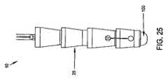
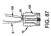
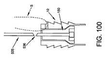
より具体的には、ここで図19を見ると、剥離した関節唇の寛骨臼への関節鏡による再縫着に使用するための新規な縫合糸アンカーシステム5が示されている。縫合糸アンカーシステム5は、全体的に、アンカー10と、アンカー10に固定された縫合糸15と、アンカー10を寛骨臼内へ送達するためのインサーター20とを備え、それによって、以下でより詳細に説明するように、縫合糸15は、剥離した関節唇を寛骨臼縁に固定するために使用されることができる。縫合糸アンカーシステム5はまた、好ましくは、構成要素を身体の外部から寛骨臼に送達するための中空ガイド25と、アンカー10用の座部を寛骨臼内に準備するために使用されることができる穿穴器(またはドリル)30とを備える。 More specifically, referring now to FIG. 19, there is shown a novel
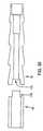
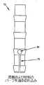
次に図19から図23を見ると、アンカー10は略円筒状本体35を備え、本体35は、遠位端40と、近位端45と、遠位端40と近位端45の間に延びる内腔50とを有する。本発明の好ましい一形態では、内腔50は、遠位端の貯蔵部55と、短い中間部分60と、細長い近位部分65とを備える。図23に示されるように、遠位端の貯蔵部55は、短い中間部分60の直径より大きい直径を有し、短い中間部分60は、細長い近位部分65の直径より大きい直径を有する。さらに、本発明の好ましい一形態では、略円筒状本体35の外表面は、骨内でのアンカー10の「保持力」を増強するように、略円筒状本体35の長さに沿って離隔された複数のリブ70を備える。本発明の特に好ましい一形態では、リブ70は、略円筒状本体35の長さをさらに複数の区間に分割し、各区間は略円錐台形の構成を有する(図21および図22)。 Referring now to FIGS. 19-23, the
略円筒状本体35の遠位端40の近く(であるが、これから離隔されている)には、略円筒状本体35の1つの側壁を完全に通って延び(しかし、他の側壁は通らない)、長手方向に延びる切れ込み75が提供される。したがって、長手方向に延びる切れ込み75は、アンカー10の内腔50と連通する。長手方向に延びる切れ込み75の遠位端は遠位助穴80で終端し、長手方向に延びる切れ込み75の近位端は近位助穴85で終端する。遠位助穴80は略円筒状本体35の遠位端40から離隔されており、したがって、中実の遠位リング90は略円筒状本体35の遠位端に位置し、それによって、略円筒状本体35の遠位端に、ある程度の構造上の完全性を提供することが理解されるであろう。 Near (but apart from) the
次に図20および図24から図26を見ると、縫合糸15は、全体的に、遠位ループ95を備え、遠位ループ95は、その遠位端において拡張部100で終端し、その近位端において近位開ループ105に接続される。より具体的には、遠位ループ95は、内腔50の短い中間部分60および細長い近位部分65を通って延びる。拡張部100は、遠位ループ95の遠位端に取り付けられた中実部材(たとえば、円柱状、円錐形など)を備えてもよいし、縫合糸15の遠位ループ95の遠位端を結ぶことなどによって形成された縫合糸の結び目を備えてもよい。拡張部100が縫合糸の結び目を備える場合、この縫合糸の結び目は、セメント、熱などによって硬化、成形、または安定化を行われてもよいし、行われなくてもよい。説明のために、拡張部100は概略的に、すなわち略円筒状の構造として、図面に示されているが、これは図をわかりやすくするためだけに行われたものであり、拡張部100は、本発明と矛盾しない他の任意の形状および/または構成(縫合糸の結び目の形状および/または構成を含む)となることができることを理解されたい。拡張部100は、略円筒状本体35の遠位端の貯蔵部55に着座するのに十分なほど小さい(たとえば、図24および図25を参照されたい)が、略円筒状本体35の半径方向の拡張を引き起こさずに略円筒状本体35の短い中間部分60に入らないことがある(たとえば、図26を参照されたい)のに十分なほど大きいようなサイズにされる。近位開ループ105は、以下で説明するように、インサーター20の内部を逆に通って延び(図19および図20)、インサーター20の近位端(図19)から出る1対の縫合糸自由端を提供する。 20 and FIGS. 24 to 26, the
次に図19および図20を見ると、インサーター20は、全体的に、それを通って延びる内腔115を有する中空のプッシュチューブ110を備える。インサーター20は、その遠位端では、アンカー10の近位端45を係合するための駆動表面120で終端し、その近位端では、ハンドル125で終端する。ハンドル125は、縫合糸15の自由端を固定するための機構、たとえば、1つまたは複数の縫合糸クリート、縫合糸スロット、縫合糸クランプなどを含むことができる。このような機構が設けられる場合、および必要に応じて、ハンドル125は、縫合糸15の自由端を解放するための1つまたは複数の解放機構も含むことができる。ハンドル125は、縫合糸15の固定された自由端に張力を加えるための1つまたは複数の機構も有することができる。縫合糸15(すなわち、縫合糸15の近位開ループ105)は、中空のプッシュチューブ110の内腔115を通って延びる。縫合糸15の近位端上でやや近位方向に向けられた張力を維持することによって(たとえば、近位開ループ105の縫合糸自由端上でやや近位方向に向けられた張力を維持することによって)、アンカー10は、中空のプッシュチューブ110の駆動表面120に対して保持され、それによって、アンカーの操作に対してある程度の制御を提供することができる。 19 and 20, the
好ましくは、アンカー10、縫合糸15、およびインサーター20はあらかじめ単一のユニットに組み立てられ、縫合糸15は、アンカー10をインサーター20の遠位端上に保持するようにやや近位の張力を有してインサーター20の内腔115を逆に通って延びる。 Preferably,
縫合糸アンカーシステム5は、好ましくは、構成要素を身体の外部から寛骨臼に誘導するための中空ガイド25も備える。より具体的には、以下で説明するように、中空ガイド25は、全体的に、その中にアンカー10およびインサーター20を摺動可能に受けるための内腔130を備える。中空ガイド25の内径は、好ましくは、アンカー10の最も大きな外部機構(たとえば、バーブ(barb)70のうちの1つまたは複数)にほぼ等しく、したがって、アンカー10は、中空ガイド25の内部の中で密接な滑りばめを形成することができる。あるいは、中空ガイド25の内径は、必要に応じて、アンカー10の外部機構よりやや小さくてもよいし、やや大きくてもよい。縫合糸アンカーシステム5が穿孔器(またはドリル)30も備える場合、中空ガイド25の内腔130は、好ましくは、以下で説明するように、穿孔器(またはドリル)30を摺動可能に受けるようなサイズにされる。中空ガイド25の遠位端は、好ましくは、以下で説明するように、関節唇を貫通して寛骨臼を係合するための鋭利な先端/縁を含む。 The
必要に応じて、次に図19および図27を見ると、縫合糸アンカーシステム5は、鋭利な遠位端135とそれに取り付けられたハンドル145を有する近位端140とを有する穿孔器(またはドリル)30も備えることができる。要素30がドリルである場合、ハンドル145は、動力を備えた駆動体などによりドリルを回しやすくするように穴をあけるための取り付け具を備えることができる。この場合もやはり、穿孔器(またはドリル)30の鋭利な遠位端135は、以下で説明するように、寛骨臼に入り込むように適合される。
本発明の新規な縫合糸アンカーシステムを使用して関節唇を関節鏡により寛骨臼に再縫着するための方法
縫合糸アンカーシステム5は、好ましくは、剥離した関節唇を寛骨臼に固定するために以下のように使用される。If desired, referring now to FIGS. 19 and 27, the
Method for Resewing Articular Lips to the Acetabulum with an Arthroscope Using the Novel Suture Anchor System of the Invention The
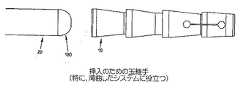
最初に、中空ガイド25の鋭利な遠位端136は、関節唇を通過させられ、アンカー10を展開可能な場所において寛骨臼に対して配置される。好ましくは、中空ガイド25の鋭利な遠位端は関節唇を貫通し、寛骨臼と相対して中空ガイドを安定化させるように寛骨臼に短い距離入る。スタイレット(たとえば、閉塞物)は、このような挿入中に中空ガイド25を満たし、したがって挿入中に関節唇の組織のコアリングを防止するために使用されることができる。穿孔器(またはドリル)30の遠位部分はまた、このような挿入中に中空ガイド25の中空先端を満たすために使用されることができる。 Initially, the sharp
次に、必要に応じて、穿孔器(またはドリル)30は、アンカー10を受けるように寛骨臼内に座部を準備するために使用されることができる。より具体的には、穿孔器(またはドリル)30が使用される場合、穿孔器(またはドリル)30の鋭利な遠位端135は中空ガイド25を通過させられ(それによって、関節唇も通過する)、アンカー10を受けるために骨の中に開口(すなわち座部)を形成するように寛骨臼内へと前進させられる。次に、中空ガイド25が静止した状態に保ちながら、穿孔器(またはドリル)30が中空ガイド25から除去される。 Next, if desired, the perforator (or drill) 30 can be used to prepare a seat in the acetabulum to receive the
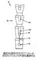
次に、その上にアンカー10を載せたインサーター20は中空ガイド25を通過させられ(それによって、関節唇も通過する)、寛骨臼内に形成された座部へと入る。アンカー10が骨の中へと前進させられるにつれて、アンカー10の本体(たとえば、リブ70)は、周囲の骨と締まりばめを形成し、それによって最初にアンカーを骨に結合する。同時に、アンカーの遠位端に位置する中実の遠位リング90は、アンカーが骨に入り込む間アンカーを損なわずに保つために必要とされる構造上の完全性をもたらす。アンカー10が寛骨臼へと適切な距離前進させられたとき、縫合糸15の近位端(すなわち、近位開ループ105)は近位方向に引っ張られ、インサーター20の遠位端は所定の位置に保持され、それによって、図26に示されるように、拡張部100を略円筒状本体35に対して近位方向に移動させ、略円筒状本体35の遠位端を強制的に分裂および拡張させ、それによりアンカー10を、したがって縫合糸15を骨にさらに結合させる。本発明の好ましい一形態では、略円筒状本体35の拡張は、略円筒状本体の円周の一部または全部に沿って発生し、略円筒状本体の円周周囲の拡張量の変動がある場合があり、たとえば図26に示される構造では、長手方向に延びる切れ込み75の方向に垂直な方向に(たとえば、図26に示される矢印の方向に)、より大きな拡張がある場合がある。略円筒状本体35の拡張の場所および大きさは、長手方向に延びる切れ込み75の数および場所、拡張部100の構成、略円筒状本体35の構成(たとえば、その内腔50および内腔に隣接する円筒状本体35の関連する側壁)などによって制御可能であることが理解されるであろう。本発明の好ましい一形態では、略円筒状本体35の拡張は、遠位端の貯蔵部55が短い中間部分60と接触するゾーンにおいて発生し、拡張は、拡張部100が比較的大きな直径の遠位端の貯蔵部55から出て比較的小さな直径の中間部分60に入るときに発生する。 Next, the
重要なことに、関節唇を所定の位置に固定するために必要とされる適度の保持力に鑑みて、アンカー10は、靱帯を所定の位置に保持するために使用される種類の従来の骨アンカーよりはるかに小さな、非常に小さいサイズを有することができる。限定ではなく例を挙げると、アンカー10は、0.8255センチ(0.325インチ)の長さと、0.16センチ(0.063インチ)の外径(非拡張時)と、0.2032センチ(0.080インチ)の外径(拡張時)とを有することができる。このサイズが小さいことによって、関節唇内で最小限の穿刺を行うこと(および、したがって関節唇内に最小限の穴を作製すること)が可能になり、したがって、関節唇組織に対する潜在的な損傷を減少させ、関節唇を通る、より正確な穿刺場所を可能にする。また、アンカー10のサイズが小さいことによって、アンカーが関節の摺動面に入り込むことを恐れずに、アンカーを寛骨臼カップの周縁のより近くに、または寛骨臼カップの周縁内に直接、置くこともできる。たとえば、寛骨臼カップの周縁近くに置かれたアンカー10を示す図28と、寛骨臼カップの周縁内に直接的に置かれたアンカー10を示す図28Aを参照されたい。これによって、上記で説明した関節唇の外がえし問題が著しく減少する、または完全になくなる。そのうえ、アンカーのサイズが小さいことによって、患者の組織に対する外傷が著しく減少する。 Importantly, in view of the moderate holding force required to fix the joint lip in place, the
アンカー10がいったん寛骨臼内に設置されると、ガイド25が手術部位から除去され、アンカー10を寛骨臼内で展開されたままにし、縫合糸15は関節唇を通って延びる。 Once the
次に、このプロセスは、関節唇を通って寛骨臼へと追加アンカーを展開するように必要に応じて繰り返されることができ、各アンカーは、関節唇を通って延びる1対の関連する縫合糸自由端を有する。 This process can then be repeated as necessary to deploy additional anchors through the articular lips to the acetabulum, each anchor being a pair of associated sutures extending through the articular lips. Has a thread free end.
最終的に、関節唇は、1つまたは複数のアンカーから出る縫合糸自由端を使用して関節唇を寛骨臼に縛り付けることによって、寛骨臼カップに固定されることができる。
本発明の新規な縫合糸アンカーシステムのためのいくつかの代替構造
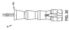
必要に応じて、次に図29から図31を見ると、展開用シリンダ150は、拡張部100の直近位にある縫合糸15の遠位ループ95上に配設されることができる。展開用シリンダ150は、拡張部100が縫合糸の結び目を備える場合に有利なことがある。というのは、展開用シリンダは、縫合糸の結び目が不均一な構成を有する場合でもアンカー本体の壁への半径方向拡張力の均一な印加を保証することができるからである。展開用シリンダ150は、縫合糸15が近位方向に引っ張られるときにアンカー10の拡張を容易にするために、斜めになった近位端155を有することができる。図29は拡張されていない状態のアンカー10を示し、図30から図31は、拡張された状態のアンカー10を示す。Finally, the articular lip can be secured to the acetabular cup by tying the articular lip to the acetabulum using a free suture end that exits one or more anchors.
Several Alternative Structures for the Novel Suture Anchor System of the Present Invention If desired, and referring now to FIGS. 29-31, the
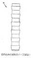
そのうえ、リブ70のうちの1つまたは複数は、図21から図23に示される構造と異なる構造を利用することができる。より具体的には、図21から図23では、リブ70のそれぞれは、円筒表面160を備える近位部分を備える。このような円筒表面は、アンカー10が寛骨臼内に配設されるときに隣接する骨を係合するための接触表面積の増加をもたらす。しかし、必要に応じて、リブ70のうちの1つまたは複数は、縫合糸15が近位方向に引っ張られるときに隣接する骨に食い込むための鋭利な近位周縁165(図29から図31)で終端することができる。 In addition, one or more of the
または、リブ70のうちの1つもしくは複数は、リブに可撓性の向上をもたらすように、図32に示すようにスロットを付けられることができる。このような構造は、寛骨臼内で展開されるときに、ばねのように、スロットの付いたリブ70をインサーター20内に嵌合するように径方向に圧縮して、次に径方向に拡張させることができるので、有利なことがある。 Alternatively, one or more of the
必要に応じて、アンカー10をインサーター20の遠位端に連結するための代替構成が、提供されることができる。より具体的には、図33および図34では、雄−雌接続が、アンカー10をインサーター20に連結するために使用され、アンカー10は雄型突出部170を有し、インサーター20は、対応する雌型凹部175を有する。図35および図36では、インサーター20は雄型突出部170を含み、アンカー10は、対応する雌型凹部175を有する。図37および図38では、インサーター20は凸状表面180を有し、アンカー10は、対応する凹状表面185を有する。本開示に鑑みて、このタイプのさらに他の構造が当業者には明らかであろう。 If desired, alternative configurations for coupling the
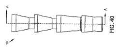
次に図39から図41を見ると、本発明の別の形態では、縫合糸15は、近位助孔85でアンカー10を出て略円筒状本体35の外側に沿って延びることが意図される。必要に応じて、スロット190は、その中に縫合糸15を収容するように、リブ70内に設けられることができる。 Turning next to FIGS. 39-41, in another form of the invention, the
本発明の別の形態では、次に図42を見ると、縫合糸15は、中実シャフト195で置き換えられることができる。より具体的には、中実シャフト195は、アンカー10の内腔50およびインサーター20の内腔115を通って延び、その遠位端上に形成された拡張部100を有する。中実シャフト195が近位方向に動くことによって、アンカー10に隣接する骨を把持させるように、拡張部100がアンカー10の遠位端を拡張する。 In another form of the invention, looking next at FIG. 42, the
必要に応じて、遠位助穴80と近位助穴85の一方または両方は省略されてもよく、長手方向に延びる切れ込み75は、一方または両方の端において穴のない(blind)表面で終端する。 If desired, one or both of the
そのうえ、必要に応じて、長手方向に延びる複数の切れ込み75は、アンカー10内に設けられることができ、たとえば、直径方向に対向する、長手方向に延びる2つの切れ込み75が設けられることができる。さらに、必要に応じて、長手方向に延びる切れ込み75は、アンカー本体の遠位端の手前で終わるのではなく、アンカー本体の遠位端までずっと延びることができる。たとえば、図43および図44を参照されたい。図43および図44は、直径方向に対向する、長手方向に延びる2つの切れ込み75を示しており、切れ込みはアンカー10の遠位端までずっと延びる。これらの2つの図は、例示的なリブ構成を示す。また、長手方向に延びる単一の切れ込み75を有するアンカー10を示す図45も参照されたい。切れ込みは、アンカーの遠位端までずっと延びる。 In addition, if desired, a plurality of longitudinally extending
必要に応じて、次に図46から図48を見ると、内腔50は、略円筒状本体35の長手方向軸205に対して偏心した長手方向軸200に沿って延びることができる。このような偏心構造は、優先的な本体の拡張を形成するように、アンカーの片側に薄い側壁を、アンカーの別の側に厚い側壁を設けることができる。 46-48, the
または、アンカー10は、図49および図50に示すように、変化する肉厚および非対称的な効果を形成するために、ある角度をなす貫通孔を備えることができる。 Alternatively, the
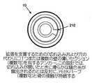
必要に応じて、次に図51を見ると、アンカー10は、長手方向に延びる切れ込み75が完全に省略されるように構成されることができる。本発明のこの形態では、アンカー10は、好ましくは、拡張部100が近位方向に押されるときに破砕する1つまたは複数の壁の薄いセクション210(図52から図54)を有して形成される。 If desired, referring now to FIG. 51, the
あるいは、本発明の別の形態では、アンカー10は、拡張部100が近位方向に動くときに、その略円筒状本体35は径方向に拡張するが、アンカーの遠位端は裂けないように構成される。図55から図60を参照されたい。この場合もやはり、円筒状本体35の拡張の方向および程度は、長手方向に延びる切れ込み75の数および場所、拡張部100の構成、略円筒状本体35の構成(たとえば、その内腔50および内腔に隣接する円筒状本体35の関連する側壁)などによって制御されることができる。
追加構造に関する詳細
アンカー10は、本発明と矛盾しない任意の材料から作製されることができ、たとえば、アンカー10は、生体適合性プラスチック(PEEKなど)、吸収性ポリマー(ポリ−L−乳酸、PLLAなど)、ヒドロゲルなどの生理活性材料、または金属(ステンレス鋼またはチタンなど)から作製されることができる。Alternatively, in another form of the invention, the
Details on Additional Structures Anchor 10 can be made from any material consistent with the present invention, for example,
縫合糸15は、本発明と矛盾しない任意の材料、たとえば、一般的な外科用縫合材料から作製されることができる。1つのこのような材料は、PEまたはUHMWPEなどの織布(woven)ポリマーである。別の材料は、UHMWPE/ポリエステルなどのコポリマー材料である。さらに別の材料は、ポリグリコール酸、ポリ乳酸、ポリジオキサノン、またはカプロラクトンなどの吸収性ポリマーである。近位ループ105は、好ましくは、#1縫合糸サイズである。あるいは、近位ループ105は、#2縫合糸サイズ、#0縫合糸サイズ、または#2−0縫合糸サイズである。遠位ループ95は、好ましくは、#2−0縫合糸サイズである。あるいは、遠位ループ95は、#2縫合糸サイズ、#1縫合糸サイズ、または#0縫合糸サイズである。 The
前述のように、拡張部100は、遠位ループ95の遠位端に取り付けられた中実部材を備えてもよいし、縫合糸15の遠位ループ95の遠位端を結ぶことによって形成された縫合糸の結び目を備えてもよい。この後者の構造では、拡張部100は、単一の結び目または複数の結び目から形成されることができる。拡張部100は、止め結び(overhand knot)または「図8」の結び目などの他の結び目とすることができる。縫合糸15はまた、拡張部100を作製するように熱形成されることもできる。これによって、拡張部100のその遠位位置からそのより近位の位置への移動をさらに可能にする、より剛性の機構が作製される。このような熱形成はまた、結び目の上で、または結び目に対して遠位の縫合糸端を密閉するために、行われることもできる。
アンカーへの作動力の制御された伝導を提供するように力を制限する力伝導機構
先行する節では、とりわけ剥離した関節唇を関節鏡により寛骨臼に再縫着するために使用することができる新規な縫合糸アンカーシステム5を開示した。上記で説明したように、新規な縫合糸アンカーシステム5は、全体的に、アンカー10と、アンカー10に固定された縫合糸15と、アンカー10を寛骨臼の中へ送達するためのインサーター20とを備える。同様に上記で説明したように、新規な縫合糸アンカーシステム5は、インサーター20がアンカー10を寛骨臼内へと送達した後、縫合糸15に張力をかけることによって、アンカー10の本体が側方に拡張し、その結果アンカーが骨に固定され、それによって縫合糸15を骨に固定するように構成される。As previously described, the
A force-conducting mechanism that limits the force to provide controlled conduction of the actuating force to the anchor. In the preceding section, it can be used, among other things, to resew a detached articular lip to the acetabulum with an arthroscope. A possible new
本発明の好ましい一形態では、縫合糸15は、1対の縫合糸、たとえば、アンカー10を通って延びる細い遠位縫合糸95と、この細い遠位縫合糸95からインサーター20の近位端に(たとえば、インサーター20のハンドルに)延びる太い近位縫合糸105とを備えることができ、したがって、太い近位縫合糸105は、細い遠位縫合糸95を近位方向に引っ張ることによってアンカーを作動させるため、およびアンカー10が展開される骨、たとえば寛骨臼に物体(たとえば、関節唇)を固定するために使用されることができる。 In a preferred form of the invention, the
そして、本発明の好ましい一形態では、新規な縫合糸アンカーシステム5は、非常に小さい規模で、たとえば、アンカー10が1.5mm程度の直径を有し、細い遠位縫合糸95が約0.3mmの直径を有する「サイズ2−0の縫合糸」であり、太い近位縫合糸105は約0.4mmの直径を有する「サイズ1の縫合糸」であるように、構成されることが意図される。 And in a preferred form of the invention, the novel
この非常に小さい構造を考えると、大きすぎる張力を縫合糸に加えることによりアンカー10の本体への意図しない損傷および/または縫合糸(特に、細い遠位縫合糸95)の破損が生じることがあるので、縫合糸に加えられる張力の大きさを制限することが極めて重要な場合がある。しかし、同時に、アンカーの適切な作動を保証するために、適切な量の力をアンカーに加えることも重要である。 Given this very small structure, applying too much tension to the suture may cause unintentional damage to the body of the
本明細書の以下の節では、アンカー10への作動力の制御された伝導を提供するように力を制限する力伝導機構を開示する。 In the following sections of this specification, a force transfer mechanism is disclosed that limits the force to provide controlled conduction of actuation force to the
本発明によれば、アンカーを骨内に着座させるように、アンカーを骨内へ送達するため、およびそのアンカーが骨内に配設される間、アンカーを作動する(すなわち、要素を近位方向に引っ張ることによって)ために使用されることができる装置を開示する。本発明の好ましい一形態では、アンカーは、アンカー(アンカーの一部またはアンカーの本体全体)を拡張および/または変形させるために(好ましくは、縫合糸に張力をかけることによって)アンカーにおいて力を加えることを必要とする拡張可能なアンカーである。本発明によれば、アンカーを作動するための(たとえば、縫合糸に張力をかけるための)装置は、力を制限する力伝導機構を利用することによって使用者は(たとえば、縫合糸に張力をかけることによって)特定の所望の力の限界まで力をアンカーに手動で加えることができ、そこで、この機構が自動的に離れ、その後、(たとえば、縫合糸に張力をかけることによって)アンカーに加えられる力はゼロ(または実質的にゼロ)に低下するという意味で、力を制限する力伝導機構を備える。力伝導機構の離脱および力を制限する態様は自動的であり、使用者によるいかなる追加の動作も必要としない。言い換えれば、力伝導機構は、アンカーに(たとえば、アンカーに接続された縫合糸に)加えられる張力の大きさが、ある一定の所定の限界を超えたとき、力伝導機構が自動的に離れ、さらなる張力がアンカーに加えられないように構成される。 In accordance with the present invention, the anchor is actuated to deliver the anchor into the bone, so that the anchor is seated in the bone, and while the anchor is disposed within the bone (ie, the element in the proximal direction). Discloses a device that can be used for In one preferred form of the invention, the anchor applies a force on the anchor (preferably by tensioning the suture) to expand and / or deform the anchor (part of the anchor or the entire body of the anchor). It is an expandable anchor that requires that. In accordance with the present invention, a device for actuating an anchor (eg, for tensioning a suture) utilizes a force transfer mechanism that limits the force, thereby allowing a user (eg, tensioning the suture). Force can be manually applied to the anchor to a certain desired force limit, where the mechanism automatically leaves and then applied to the anchor (eg, by tensioning the suture) It is provided with a force transfer mechanism that limits the force in the sense that the force exerted drops to zero (or substantially zero). The disengagement of the force transfer mechanism and the manner of limiting the force is automatic and does not require any additional action by the user. In other words, the force transfer mechanism automatically leaves the force transfer mechanism when the amount of tension applied to the anchor (eg, to a suture connected to the anchor) exceeds a certain predetermined limit, Configured so that no additional tension is applied to the anchor.
このような力を制限する機構の代替形態は、(i)固定の移動距離にわたって可変の力を加える機構、または(ii)使用者にアンカーへの作動力の伝導を能動的に制御することを要求する機構、のどちらかである。いずれの手法も、本発明によって提供される種類の力を制限する機構にとって好ましくない。重要なことに、力を制限する機構は、縫合糸の伸長、アンカー材料の性質、および必要とされる作動時移動距離などのデバイス変数、ならびに骨のタイプおよび骨質などの解剖学的構造の変数とは無関係である。たとえば、等価な骨質では、縫合糸のより大きな伸長を有するデバイスは、アンカーにおいて、部分的な作動のみを見ることができる。しかし、力を制限する機構は、縫合糸の伸長とは無関係であり、したがって、一貫した特定の力に達するまでアンカーを作動する。限定ではなく例を挙げると、縫合糸における伸長の量は、アンカーによって必要とされる作動時移動距離を大きく超えることができ、たとえば、縫合糸は、縫合糸が張力をかけられるときインサーターの長さに沿って10mm〜15mm伸長することができるが、アンカーは、1mmの作動時移動距離のみを必要とすることができる。この状況では、縫合糸の伸長によって、所望の作動力をアンカーに確実に加えることが事実上不可能となることがある。そのうえ、密度の高い骨は、密度の低い骨がアンカーの側方への拡張に抵抗するよりも強く、アンカーの側方への拡張に抵抗する。したがって、骨の密度の高い場合、作動用縫合糸に加えられる力は、縫合糸によって受け入れられる(すなわち、吸収される)ことがあり、したがって不完全なアンカーの拡張が発生することがある。さらに、使用者にアンカーへの作動力の伝導を能動的に制御することを要求するデバイスは、使用者による過失およびデバイスの機能の不必要な複雑化の可能性をもたらす。 Alternative forms of such force limiting mechanisms include (i) a mechanism that applies a variable force over a fixed travel distance, or (ii) actively controlling the conduction of actuation force to the anchor to the user. Either of the requested mechanisms. Neither approach is preferred for mechanisms that limit the type of force provided by the present invention. Importantly, the mechanisms that limit the force include device variables such as suture stretch, anchor material properties, and required working distance traveled, and anatomical structural variables such as bone type and bone quality. It has nothing to do with it. For example, with equivalent bone quality, a device with a greater extension of the suture can only see partial actuation at the anchor. However, the mechanism that limits the force is independent of the suture stretch and thus actuates the anchor until a consistent specific force is reached. By way of example and not limitation, the amount of extension in the suture can greatly exceed the working travel distance required by the anchor; for example, the suture can be inserted into the inserter when the suture is tensioned. While it can extend 10 mm to 15 mm along the length, the anchor can only require an operating distance of 1 mm. In this situation, stretching the suture may make it virtually impossible to reliably apply the desired actuation force to the anchor. Moreover, dense bone is stronger and resists lateral expansion of the anchor than low density bone resists lateral expansion of the anchor. Thus, if the bone density is high, the force applied to the actuation suture may be accepted (ie, absorbed) by the suture, and thus incomplete anchor expansion may occur. In addition, devices that require the user to actively control the conduction of actuation force to the anchor introduce the possibility of user error and unnecessary complexity of the device's functionality.
前述の内容のために、本発明は、アンカーへの作動力の制御された伝導を提供するように力を制限する力伝導機構を提供する。 Because of the foregoing, the present invention provides a force transfer mechanism that limits the force to provide controlled conduction of actuation force to the anchor.
説明をわかりやすくするため、力を制限する新規な機構を、その太い近位縫合糸105を近位方向に引っ張ることによって作動力をアンカー10に加え、それによって、その細い遠位縫合糸95に縫合糸の結び目(たとえば、拡張部100)またはPEEKシリンダ(たとえば、展開用シリンダ150)を近位方向に移動させ、それによってアンカー10を拡張させて骨内に設置させるという状況において、以下で概略的に説明する。
ウイッシュボーン状機構
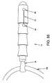
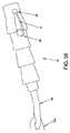
次に図61から図68を見ると、アンカーへの、たとえばアンカー10の太い近位縫合糸105への、作動力の制御された伝導を提供するように力を制限するウイッシュボーン状力伝導機構300が示されている。ウイッシュボーン状機構300は、上記で説明したインサーター20のハンドル125に組み込まれることを意図したものであり、これによって、ハンドル125に、これまで示した構成から変更された構成をとらせることができる。本発明の好ましい一形態では、ウイッシュボーン状機構300は、全体的に、ハンドル305と、蓋310と、クリート315と、ウイッシュボーン320と、指掛け325とを備える。ウイッシュボーン状装置300はまた、近位ばね330と、遠位ばね335と、ウイッシュボーン状ばね340とを備える。For clarity of explanation, a novel mechanism for limiting force is applied to the
Wishbone-like Mechanism Turning now to FIGS. 61-68, a wishbone that limits the force to provide controlled conduction of actuation force to the anchor, eg, to the thick
ウイッシュボーン320、指掛け325、およびウイッシュボーン状ばね340は、ウイッシュボーン状機構300の力を制限する態様ならびにハンドル305および蓋310が作動を含んで誘導するように作用することを可能にする重要な構成要素である。さらに、以下で説明するように、装置がその包装に包まれている間、および/または指掛け325への作動力の伝導の前に、近位ばね330は、作動終了時(すなわち、以下で説明するように、ウイッシュボーン320が指掛け325から飛び出すとき)にハードストップ(hard stop)を抑制し(dampen)、遠位ばね335は、縫合糸(たとえば、太い近位縫合糸105)にかかる張力を維持する。 The
ウイッシュボーン状機構300は、蓋310をインサーター20の中空プッシュチューブ110の近位端に取り付けることによってインサーター20に統合され、アンカー10の太い近位縫合糸105は、クリート315への解放可能な接続のために中空プッシュチューブ110を上方に延び、ハンドル305は、使用者の手で握持されるように構成され、指掛け325は、使用者の人さし指および中指で握持されるように構成される。 The
縫合糸アンカー(たとえば、アンカー10)の送達には、ドリルビットまたは穿孔器のどちらかによって作製される、骨内の穴が必要である。次に、アンカーが、その穴に、中空プッシュチューブ110上に設けられた印(図示せず)によって示される特定の深さまで挿入される。アンカーがいったん適切な深さに位置すると、アンカーは作動ステップを必要とする。この作動ステップでは、縫合糸(たとえば、細い遠位縫合糸95)の遠位端における縫合糸の結び目(たとえば、拡張部100)および/またはPEEKシリンダ(たとえば、展開用シリンダ150)がアンカーによって近位方向に引っ張られ、以前に説明したようにアンカーを拡張させる。アンカー10内での縫合糸の結び目(たとえば、拡張部100)および/またはPEEKシリンダ(たとえば、展開用シリンダ150)の近位方向の前進ならびにそれによるアンカーの拡張は、力を制限するウイッシュボーン状機構300によって制御される。力を制限するウイッシュボーン状機構300は、インサーター20の近位(すなわち、ハンドル)端に配設され、これを構成し、蓋310はインサーター20の中空プッシュチューブ110に接続される。力を制限するウイッシュボーン状機構300は、使用者によって、インサーター20の近位(ハンドル)端に配設された指掛け325を介して片手で作動される。 Delivery of a suture anchor (eg, anchor 10) requires a hole in the bone created by either a drill bit or a punch. The anchor is then inserted into the hole to a specific depth indicated by a mark (not shown) provided on the
アンカーの最適な拡張および引き出されることへの最大の抵抗を保証するため、アンカーの拡張は、所定の作動力を加えることによって実施される。力を制限するウイッシュボーン状機構300を利用することによって、使用者は、力の所定の最大レベルまでアンカーを作動および拡張することができ、力のその所定の最大レベルに到達すると、ウイッシュボーン状機構は自動的に離れ、それによって、使用者がさらなる力をアンカーに加えるのを防止するが、ウイッシュボーン状機構は、力のその所定の最大レベルがアンカーに加えられるまで、力伝導機構を離さない。したがって、ウイッシュボーン状機構300は、毎回適切なレベルの張力がアンカー10に加えられることを保証する(もちろん、作動中に適切なレベルの力が指掛け325に供給される場合)。
ウイッシュボーン状機構300の概要
上記で説明したように、アンカー10が骨の穴の中に配置された後、アンカー10は、アンカー本体を拡張することによって設置される。これは、細い遠位縫合糸95(ならびに、したがって縫合糸の結び目100および/またはPEEKシリンダ150)を近位方向に引っ張ることによって実施される。同様に上記で説明したように、細い遠位縫合糸95は、(ハンドルまで延びる)太い近位縫合糸105を近位方向に引っ張ることによって、近位方向に引っ張られる。ウイッシュボーン状機構300では、以下で説明するように、太い近位縫合糸105の近位端はクリート315に固定され、クリート315そのものは、ウイッシュボーン320によって指掛け325に解放可能に接続される。使用者の視点からは、アンカーの作動は、ウイッシュボーン状装置300が自動的に離されるまで指掛け325を近位方向に引っ張ることによって実施され(図68)、その結果、指掛け325の任意のさらなる近位方向移動は近位ばね330によって抑制される。アンカーの作動中、および指掛け325が近位ハードストップ345を係合する前に、ウイッシュボーン状装置300は「カチッ」という可聴音をたて、同時に、指掛け325における抵抗が著しく低下する。これは、力の所定の最大レベルに到達したこと、およびウイッシュボーン状装置300が自動的に離れた(すなわち、以下で説明するように、ウイッシュボーン320が指掛け325から飛び出すことによって)ことを示す。この時点で、アンカーは骨の中で拡張されており、次に、太い近位縫合糸105の近位端はクリート315から解かれることができ、インサーター20(ウイッシュボーン状機構300を含む)は患者から除去されることができ、アンカー10は骨に固定されたままであり、縫合糸105は骨から延びる。
ウイッシュボーン状装置300の段階的な機能
1.使用者が、2本の指で指掛け325を引っ張る。これによって、使用者により加えられた力が指掛け325からウイッシュボーン320に伝達され、ウイッシュボーン320の2つのアーム350(図62)が張力をかけて引っ張られる。ウイッシュボーン320の2つのアーム350は、最初は、ばねの付いたスナップばめによって、指掛け325の穴355の中に一緒に保持される(図62)。このスナップばめは、好ましくは、ウイッシュボーン状突出部356(図62)と指掛け狭窄部(finger pull narrowing)357の係合によって形成される(図62)。In order to ensure optimum expansion of the anchor and maximum resistance to withdrawal, the expansion of the anchor is performed by applying a predetermined actuation force. By utilizing the wishbone-
Overview of
Stepwise functions of the
2.次に、力がウイッシュボーン320から太い近位縫合糸105(すなわち、インサーター20の中空プッシュチューブ110を貫通し、アンカー10を通って延びる細い遠位縫合糸95に取り付けられる縫合糸105)に伝達される。より具体的には、太い近位縫合糸105の近位端はクリート315に巻き付けられ、クリート315はウイッシュボーン320に取り付けられ、したがって、ウイッシュボーン320を近位方向に引っ張ることによって、太い近位縫合糸105が近位方向に引っ張られる。クリート315に巻き付けられた太い近位縫合糸105は、クリート315の中央に形成された穴360(図63および図64)から出て、たとえば開口(たとえば、溝または穴)365(図62)を経由して蓋310を通り、次にインサーター20の中空プッシュチューブ110を下って、ウイッシュボーン320の中心軸を下方に延びる。 2. The force is then applied from the
3.クリート315に巻き付けられ細い遠位縫合糸95まで下方に延びてこれを通る太い近位縫合糸105は、力を指掛け325から細い遠位縫合糸95に伝達し、これによって、細い遠位縫合糸95の結び目の付いた遠位端100および/またはPEEKシリンダ150は近位方向に移動させられ、したがってアンカーの拡張を引き起こす。図65(アンカー10をその未展開構成で示す)および図66(アンカー10をその展開構成で示す)を参照されたい。 3. A thick
4.指掛け325において使用者によって加えられる初期の力は小さく、縫合糸の伸長の主な原因となる。この小さい力によって、ウイッシュボーン320の非常に小さな圧縮がもたらされる。 4). The initial force applied by the user at the
5.縫合糸が伸長した後、ウイッシュボーン状突出部356が指掛け325内の指掛け狭窄部357(図62)に載置されると、指掛け325とウイッシュボーン320の間の伸展力が増加し、ウイッシュボーン320のアーム350がウイッシュボーン状ばね340の力に逆らって内側に圧縮され始める。図67を参照されたい。 5. When the wishbone-like projecting
6.力の所定の最大レベル(たとえば、44.4822±8.89644N(10±2lbf))では、ウイッシュボーン320のアーム350は、指掛け325とウイッシュボーン320を分離可能にするのに十分なほど圧縮される。ウイッシュボーン320が指掛け325を離す力は、ウイッシュボーン状突出部356および指掛け狭窄部357に固有の特性を含めて、材料選択ならびにウイッシュボーン320および指掛け325の幾何学的形状によって定められる。とりわけ、離脱が発生する力は、ウイッシュボーン状突出部356と指掛け狭窄部357の間の重複(すなわち圧縮距離)の量、接触面の角度、接触面の表面仕上げ、ばね340の動力などによって決定される。図67および図68を参照されたい。 6). At a predetermined maximum level of force (eg, 44.4822 ± 8.88964N (10 ± 2 lbf)), the
7.ウイッシュボーン320と指掛け325がいったん分離すると、使用者は、さらなる力を縫合糸に加えることができず、したがって、さらなる力をアンカーに加えることはできない。
ウイッシュボーン状機構の変形形態
前述の内容に加えて、ウイッシュボーン状機構の力を制限する機構は、以下の設計代替形態によって提供されることができる。7). Once
Wishbone-like Mechanism Variations In addition to the foregoing, a mechanism for limiting the force of a wishbone-like mechanism can be provided by the following design alternatives.
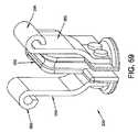
(i)ウイッシュボーン状ばねがない。ウイッシュボーン320のアーム350同士の間の圧縮ばね340は省略されることができ、ウイッシュボーン状圧縮ばね340の機能は、ウイッシュボーンを形成するために使用される材料のばね特性を使用することによって、またはウイッシュボーンの幾何学的形状を使用することによって、またはこれら両方によって、提供されることができる。より具体的には、ウイッシュボーン320は、ばね鋼などの弾性金属から、または弾性ポリマーから、製造され、それによって、必要とされるばね特性をウイッシュボーン320のアーム350に提供することができる。あるいは、ウイッシュボーン320は、鋼/ポリマー混成物として製造されることができ、アーム350はばね鋼から形成され、本体370はポリマーから形成される(図69)。当業者には理解されるように、ウイッシュボーン320の厚さおよび形状は、圧縮ばねと同じ効果を有する慣性モーメントを達成するように設計されることができる(図69および図70)。 (I) There is no wishbone spring. The
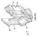
(ii)定置クリート。クリート315は、ハンドル305と一体に、すなわち、クリート315が事実上ハンドル305に固定される(図71)ように、形成されることができる。この場合、縫合経路はクリート315から遠位方向に走行し、ハンドル305と蓋310の接合部において(たとえば、371において)ハンドル305に巻き付き、ウイッシュボーン320に(たとえば、372において)巻き付いてから、インサーター20の中空プッシュチューブ110の内部に入る(図72)。この設計では、指掛け325が使用者によって近位方向に移動させられると、太い近位縫合糸105がウイッシュボーン320に対して摺動する。また、この設計では、指掛け325で使用者により知覚される作動力は、アンカーに加えられる力の約2倍である。 (Ii) Stationary cleat. The
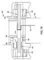
(iii)回転作動。使用者が指掛け325を近位方向に引っ張ってアンカーを作動させる代わりに、使用者は、ハンドル305の近位端にある、つまみ375を回転させることができる。つまみ375は、アンカーを作動させるように、この使用者により加えられる回転を、(クリート315に固定された)ウイッシュボーン320を引っ張る線形作動に変換する。図73を参照されたい。より具体的には、本発明のこの形態では、つまみ375を回転させることによって、プルチューブ376の螺旋ねじ377とつまみ378の螺旋溝377の係合により、ハンドル305内でのプルチューブ376の長手方向の動きが引き起こされる。プルチューブ376の遠位端は、指掛け325の対応する部分に類似した構成を有し、すなわち、プルチューブ376は、ウイッシュボーン320のアーム350を受けるための穴355と、ウイッシュボーン320の突出部356と係合するための狭窄部357とを含む。この構造の結果、つまみ375が適切に回転されると、プルチューブ376は、近位方向に引っ張るウイッシュボーン320内を長手方向に横断し、それによって、クリート315に取り付けられた太い近位縫合糸105(クリート315はウイッシュボーン320に取り付けられるので)に力を加える。一代替実施形態では、次に図74を見ると、クリート315はハンドル305上に取り付けられ、縫合糸は、ウイッシュボーン状の近位方向移動によって縫合糸が近位方向に引っ張られるように、(たとえば、図72の372で示される形に類似した形で)ウイッシュボーン状の一部分の周りに縫合糸を通すことによって、張力をかけられる。 (Iii) Rotation operation. Instead of the user pulling the
(iv)そのうえ、使用者が指掛け325を近位方向に引っ張ってアンカーを作動させる、または、つまみ375を回転させてアンカーを作動させる代わりに、アンカーを作動させるための、使用者制御の他の形態が提供されることができる。限定ではなく例を挙げると、使用者は、レバーを引っ張る、トリガを圧迫する、タブを引っ張るなどによって、アンカーを作動させることができる。本開示に鑑みて、これらおよび他の構造が当業者には明らかであろう。
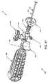
スプーリング機構
本発明の別の形態では、次に図75から図79を見ると、ウイッシュボーン状機構300は、力を制限する機構が指掛け325内に完全に内蔵されるスプーリング機構380で置き換えられることができる。より具体的には、本発明のこの形態では、太い近位縫合糸105は、指掛け325の内部に配設され選択的に回転可能なシャフト385に巻き付けられる。本発明のこの形態によれば、シャフト385は、力の所定の最大レベルに到達するまで回転が防止され、その後、シャフト385は自由に回転することが可能であり、太い近位縫合糸105はシャフトから解かれ、その結果、太い近位縫合糸105への力の印加が終了する。(Iv) Additionally, instead of the user pulling the
Spooling Mechanism In another form of the invention, referring now to FIGS. 75-79, the
以下の段階的な説明では、スプーリング機構380の構造および機能についてさらに説明する。 In the following step-by-step description, the structure and function of the
1.使用者が、2本の指で指掛け325を引っ張る。指掛けの中では、反対方向を向いた等しい力が、シャフト385上に巻かれた太い近位縫合糸105に伝達される。図75を参照されたい。 1. The user pulls the
2.太い近位縫合糸105はシャフト385に巻き付けられ、近位方向に向けられた力が指掛け325に加えられることによって太い近位縫合糸105に力が加えられると、シャフト385に固定的に固定され、通常は指掛け325内のスロット400の中に配設される指部395を有するキー付きカラー390が、指部395とスロット400の壁の係合によってシャフト385が回転するのを防止する。図76を参照されたい。 2. The thick
3.さらに、収縮力が指掛け325を介してシャフト385に加えられると、反対方向を向いた等しい力が、シャフト385から、シャフト385を回転可能に支持するその2つの軸取り付け具401に、したがって指掛け325の内部で2つの軸取り付け具401を弾性的に支持する(および、したがって指掛け325の内部でシャフト385を弾性的に支持する)2つの圧縮ばね405に加えられる。圧縮ばね405は、最初は、シャフト385が指掛け325の内部で遠位方向に引っ張られるのを防止する(および、したがって、最初は、キー付きカラー390がその指部395を指掛け325内のスロット400から引っ込めるのを防止する)。その結果、指掛け325に力を最初に加えることは、太い近位縫合糸105に伝搬される。 3. Furthermore, when a contraction force is applied to the
4.前述のように、指掛け325において使用者によって加えられる初期の力は小さく、縫合糸の伸長の主な原因となる。この小さい力によって、指掛け325内でシャフト385を支持する2つの圧縮ばね405の非常に小さな圧縮がもたらされる。その結果、キー付きカラー390の指部395は指掛け325内のスロット400に係合されたままであり、シャフト385は指掛け325に回転可能に係止されたままであり、指掛け325に加えられた力は太い近位縫合糸105に伝搬される。 4). As described above, the initial force applied by the user at
5.縫合糸が伸長した後、指掛け325内のシャフト385を支持する圧縮ばね405に加えられる力が増加し、シャフト385は、ばね405の力に逆らって、指掛け325に対して遠位方向に移動し始める。図77を参照されたい。 5. After the suture is stretched, the force applied to the
6.力の所定の最大レベル(たとえば、44.4822±8.89644N(10±2lbf))では、シャフト385を支持するばね405は、キー付きカラー390の指部395が指掛け325内のスロット400から引っ込められる点まで圧縮される。この点では、指掛け325内のばね406は、キー付きカラー390の指部395が指掛け325内のスロット400から少し離れて、指掛け325内に形成された大きな空洞407と位置合わせされるように、およびシャフト385がこの時点で指掛け325の内部で自由に回転するように、シャフト385およびキー付きカラー390を側方に押す。その結果、シャフト385は指掛け325の内部で自由に回転し、それによって、太い近位縫合糸105における張力を解放する。図78を参照されたい。 6). At a predetermined maximum level of force (eg, 44.4822 ± 8.88964N (10 ± 2 lbf)), the
7.このようにシャフトが回転すると、使用者は、さらなる力を太い近位縫合糸105に加えることができず、したがって、使用者は、さらなる力をアンカー10に加えることができない。図79を参照されたい。 7). As the shaft rotates in this manner, the user cannot apply additional force to the thick
8.次に、使用者は、スプーリング機構380に対してさらなるステップを行うことを必要とすることなく、インサーターを患者の身体から除去することができる。インサーターが除去されると、太い近位縫合糸105は、シャフト385から簡単に巻き戻される(すなわち、ほどかれる)。
二重楔機構
本発明の別の形態では、力を制限する(力を制御する)機構は、図80および図81に示される二重楔機構435を備えることができる。この二重楔機構では、ばね式の(spring−loaded)2つの楔440を使用して、力が指掛け325に加えられるとクリート315を指掛け325に保持し、それによって、クリート315に固定された太い近位縫合糸105に力を加える。力の所定の最大レベルでは、ばね式の楔440に対してクリート315により加えられる力によって、ばね式の楔は、クリート315から離れるように、遠位方向および横方向に摺動し、それによってクリート315を指掛け325から解放し、指掛け325が近位方向に移動したときにクリート315が静止したままであることを可能にし、それによって太い近位縫合糸105への力の印加を終了する。8). The user can then remove the inserter from the patient's body without requiring further steps on the
Double Wedge Mechanism In another form of the invention, the force limiting (controlling force) mechanism can comprise a
より具体的には、次に図80および図81を見ると、指掛け325は、それを通って延びる開口442を有するプレート441と、その上に取り付けられた1対の対向する傾斜したガイド443とを備える。楔440は、楔440が近位方向に移動すると、楔同士がより近づくように、および楔440が遠位方向に移動すると、楔同士が離れるように、ガイド443に沿って載置される。ばね444は楔440を近位方向に付勢し、したがって楔440をまとめて付勢する。楔440は突出部440Aを含み、突出部440Aは、楔が近づくと(たとえば、図80に示される位置において)楔440同士の間にクリート315を締着するが、楔が離隔されると(たとえば、図81に示される位置において)楔440同士の間にクリート315を締着できない。 More specifically, referring now to FIGS. 80 and 81, the
使用に際して、二重楔機構435は、図80に示される位置において開始される。近位方向の力が指掛け325に加えられ、これによって、近位方向の力がプレート441に加えられる。プレート441が近位方向に移動し始めると、太い近位縫合糸105は最初に伸長し、ばね444が、楔440を近位にまとめて保つことを可能にするが、指掛け325およびプレート441がさらに近位方向に移動すると、太い近位縫合糸105における張力が増大する。力の所定の最大レベル(たとえば、44.4822±8.89644N(10±2lbf))では、ばね444の動力を上回り、したがって、楔440は遠位方向および側方に自由に移動し(図81)、それによって、クリート315を突出部440Aから、したがってプレート441および指掛け325から解放し、それによって、太い近位縫合糸105にかかる張力を解放する。したがって、二重楔機構435では、指掛け325に加えられる力は、その力のレベルがある一定の所定のレベルに到達するまで、二重楔機構435を介して太い近位縫合糸105に伝搬され、その結果、力伝導機構は使用不能となり、太い近位縫合糸105への力の印加は完全に終了されることがわかるであろう。
縫合糸切断機構
本発明の別の形態では、力を制限する機構は、図82および図83に示される縫合糸切断機構445を備えることができる。この縫合糸切断機構445を利用することによって、使用者は太い近位縫合糸105に力を加えることができ、次に、力の所定の最大レベルに到達すると、縫合糸の近位端は、指掛け325上に配置される刃450によって切断される。太い近位縫合糸105の切断によって、力伝導機構は使用不能となり、縫合糸にかかる張力が終了する。In use, the
Suture Cutting Mechanism In another form of the invention, the force limiting mechanism can comprise a
本質的には、縫合糸切断機構445では、縫合糸は、インサーター20の中空プッシュチューブ110を上方に延び、ハンドル305を通る。縫合糸は、指掛け325に取り付けられた自由に回転するシャフト455に太い近位縫合糸105を巻き付け、次に縫合糸の端を指掛け325上の取り付け具456に固定することによって、指掛け325に取り付けられる。その結果、太い近位縫合糸105が損なわれない限り、指掛け325に加えられる近位方向の力によって、縫合糸は張力を加えられる。力の所定の最大レベルに到達すると、刃450が太い近位縫合糸105の近位端を切断する。縫合糸105の近位端がいったん切断されると、縫合糸105にかかる張力が解放される。というのは、縫合糸105は、指掛け325に取り付けられた自由に回転するシャフト455に巻き付けられ、もはや指掛け325上の取り付け具456に固定されないからである。縫合糸105にかかる張力が解放されるので、使用者がデバイスを患者から除去すると、縫合糸105は、回転シャフト455から自由に巻き戻される。したがって、太い近位縫合糸105を切断すると、力伝導機構が離れ、縫合糸にかかる張力が終了する。 In essence, in the
より具体的には、本発明の好ましい形態では、指掛け325は1対の軸棒460を備え、軸棒460の上には、台(platform)465が移動可能に取り付けられる。刃450は、台465の下面に面するように指掛け325に固定的に取り付けられ、指掛け325は、太い近位縫合糸105をそれに通過させるための開口466を備える。1対のばね470は、指掛け325から離れるように台465を付勢する。台465は、自由に回転するシャフト455を担持し、シャフト455の周囲には、太い近位縫合糸105が巻き付けられる。縫合糸105の近位端は、自由に回転するシャフト455から外れ、柱471および別の柱472の周りに通され、次いで取り付け具456で終端する。したがって、縫合糸区間473は、柱472と取り付け具456の間に延びる。この構造の結果、太い近位縫合糸105の端が取り付け具456に固定されるので、指掛け325に加えられる近位方向の力によって、張力が太い近位縫合糸105に加えられる。 More specifically, in a preferred embodiment of the present invention, the
指掛け325に加えられる引っ張り力が、前述の力の所定の最大レベルを下回るとき、ばね470は、指掛け325から離れるように、および縫合糸区間473を切断刃450から離隔して保つように、台465を近位方向に付勢されるように保つ。しかし、指掛け325に加えられる引っ張り力が、前述の力の所定のレベルを超えると、ばね470の動力を上回り、指掛け325と台465の間の間隙が閉じて、その結果、切断刃450は縫合糸区間473を係合し、それによって太い近位縫合糸105を断ち切る。その結果、太い近位縫合糸105はもはや取り付け具456に固定されず、したがって、自由に回転するシャフト455は回ることができ、太い近位縫合糸105は自由に回転するシャフト455から巻き戻され、それによって太い近位縫合糸105にかかる張力を解放することを可能にする。 When the pulling force applied to the
一代替実施形態では、縫合糸105は、台465に直接取り付けられる(すなわち、自由に回転するシャフト455はない)。指掛け325に加えられる引っ張り力が、前述の力の所定のレベルを超えると、ばね470の動力を上回り、指掛け325と台465の間の間隙が閉じて、その結果、切断刃450は縫合糸区間473を係合し、それによって太い近位縫合糸105を断ち切る。その結果、太い近位縫合糸105はもはや取り付け具456に固定されず、太い近位縫合糸105は台465から分離され、それによって太い近位縫合糸105にかかる張力を解放することを可能にする。
代替の縫合糸切断機構
本発明の別の形態では、力を制限する機構は、図84および図85に示される代替の縫合糸切断機構485を備えることができる。アンカー10が、その遠位端に拡張部100を有する細い遠位縫合糸95によって移動される展開用シリンダ150を備え、細い遠位縫合糸95自体が、インサーター20の中空プッシュチューブ110へと上方に延びる太い近位縫合糸105によって移動される、本発明のこの形態では、太い近位縫合糸105は、インサーター20の中空プッシュチューブ110の内部に配設された可動シャフト486に連結される(この実施形態では、縫合糸105は、組織を骨に固定する働きをしなくてもよく、むしろ、図示されない別の縫合糸がアンカーの本体に固定され、組織を骨に固定するために使用されてもよい)。太い近位縫合糸105は、可動シャフト486に形成された直径方向に対向する開口488を通って延びる区間487を有するループを備えることができ、区間487は、可動シャフト486の中心内腔にまたがる。インサーター20は、可動シャフト486の中心内腔の中に配設される刃490を有することができる。本発明のこの形態では、刃490は(たとえば、コネクタ491によって)指掛け325に固定され、可動シャフト486は、ばね500によって指掛け325から離れるようにばね付勢される本体495に固定される。本発明のこの形態では、指掛け325に加えられる力のレベルが前述の力の所定の最大レベルを下回る限り、ばね500は、本体495を、指掛け325から離れて付勢されるように保ち、したがって刃490を、太い近位縫合糸105によって形成される縫合糸区間487から離れるように保ち、その結果、指掛け325の近位運動によって、近位方向の力が太い近位縫合糸105に加えられ、それによってアンカーを作動する。しかし、指掛け325に加えられる力のレベルが前述の力の所定の最大レベル(たとえば、44.4822±8.89644N(10±2lbf))に到達するとすぐに、ばね500の動力を上回り、指掛け325は本体495に近づき、それによって切断刃490を太い近位縫合糸105によって形成される縫合糸区間487と係合させ、それによって太い近位縫合糸105を切り、アンカーへの作動力の印加を終了する。In one alternative embodiment, the
Alternative Suture Cutting Mechanism In another form of the invention, the force limiting mechanism can comprise an alternative
言い換えれば、本発明のこの形態では、指掛け325に加えられる力のレベルが前述の力の最大レベルを下回る限り、指掛け325に加えられる力が本体495に、したがって可動シャフト486に、したがって太い近位縫合糸105に伝達され、それによってアンカーを作動させ、ばね500は、刃490を太い近位縫合糸105の区間487から分離して保つのに十分なほど本体495を指掛け325から分離して保ち、それによって太い近位縫合糸105の完全性を維持する。しかし、指掛け325に加えられる力のレベルが前述の力の最大のレベルに到達するとすぐに、ばね500の動力を上回り、したがって、本体495と指掛け325の間の間隙が減少し、それによって刃490に太い近位縫合糸105の区間487を係合させ、縫合糸を切らせる。これによって、力伝導機構が離れ、縫合糸105にかかる張力が終了する。
ドッグボーン状機構
本発明の別の形態では、力を制限する機構は、図86に示されるドッグボーン状機構505を備えることができる。ドッグボーン状機構505を利用することによって、使用者は、指掛け325を近位方向に引っ張ることによって、クリート315に固定された太い近位縫合糸105に力を加えることができ、ドッグボーン510は、2つの部品の間(すなわち、指掛け325とクリート315の間)に力を伝達する。ドッグボーン510は、前述の力の所定の最大レベルを下回る力のレベルでは、ドッグボーン510は損なわれていないままであり、指掛け325とクリート315の間に力を伝達するように構成される。しかし、ドッグボーン510はまた、前述の力の所定の最大レベルより上の力のレベルでは、ドッグボーン510は破断し、もはや指掛け325とクリート315の間に力を伝達しないようにも構成される。したがって、本発明のこの形態では、ドッグボーン510は、指掛け325に加えられる力が前述の力の所定の最大レベルに到達するとすぐに力の伝達を終了させるという意味で、機械的ヒューズとして効果的に作用する。ドッグボーン510の破断力は、ドッグボーンの材料の選択および幾何学的形状によって定められることが理解されるであろう。
さらなる「制御される構成要素の故障」設計
上記で説明したドッグボーン状機構505では、力伝導機構の力を制限する機構は、ドッグボーンの「制御される構成要素の故障」によって提供されることが理解されるであろう。本質的には、この設計で、構成要素は「機械的ヒューズ」として作用するように設計され、それによって、加えられる力が前述の力の所定の最大レベルを超えると意図的に故障し、それによって、アンカーアセンブリへの作動力の印加を終了する。「機械的ヒューズ」として作用する構成要素は、構成要素の故障が骨内でのアンカー固定の完全性を傷つけないように選択される。In other words, in this form of the invention, as long as the level of force applied to the
Dogbone Mechanism In another form of the invention, the force limiting mechanism may comprise a
Further “Controlled Component Failure” Design In the dogbone-
ドッグボーン状機構の「制御される構成要素の故障」スキームを使用する多数の他の設計を提供可能であることが理解されるであろう。 It will be appreciated that many other designs using the “controlled component failure” scheme of the dogbone mechanism can be provided.
したがって、たとえば、次に図87および図88を見ると、本発明の一形態では、太い近位縫合糸105は、加えられる力が前述の力の所定の最大レベルを超えるときに破断するように作られることができる(これらの図および以降の図では、理解しやすさを向上させるために、インサーターが図面から省略されていることを理解されたい)。もちろん、本発明のこの形態では、太い近位縫合糸105は、加えられる力が前述の力の所定の最大レベルを超えるときに破断するように設計されるので、追加の縫合糸Sは、組織を骨に固定するために設けられる。本発明の一代替形態(図示せず)では、細い遠位縫合糸95は、加えられる力が前述の力の所定の最大レベルを超えるときに破断するように作られることができる。 Thus, for example, referring now to FIGS. 87 and 88, in one form of the present invention, the thick
または、近位方向の力を細い遠位縫合糸95に加えるために太い近位縫合糸105の代わりに機械的フック515が使用される図89および図90に示されるように、機械的フック515は、加えられる力が前述の力の所定の最大レベルを超えるときに故障する(たとえば、屈曲によって曲がる)ように作られることができる。もちろん、本発明のこの形態では、機械的フック515は、加えられる力が前述の力の所定の最大レベルを超えるときに故障するように設計されるので、追加の縫合糸Sは、組織を骨に固定するために設けられる。 Alternatively,
または、近位方向の力を細い遠位縫合糸95に加えるために太い近位縫合糸105の代わりにロッド520が使用される図91および図92に示されるように、ロッド520は、加えられる力が前述の力の所定の最大レベルを超えるときに(たとえば、細い遠位縫合糸95がロッド520の区間521を断裂させることによって)故障するように作られることができる。細い遠位縫合糸95がロッド520の区間521を断裂させる力はロッド520および細い遠位縫合糸95の材料の選択および幾何学的形状によって定められることが理解されるであろう。もちろん、本発明のこの形態では、ロッド520は、加えられる力が前述の力の所定の最大レベルを超えるときに故障するように設計されるので、追加の縫合糸Sは、組織を骨に固定するために設けられる。 Alternatively,
または、近位方向の力を展開用シリンダ150に加えるために細い遠位縫合糸95と太い近位縫合糸105の両方の代わりにロッド525が使用される図93および図94に示されるように、展開用シリンダ150は、加えられる力が前述の力の所定の最大レベルを超えるときに故障するように作られることができる。具体的には、本発明の一形態では、ロッド525は、展開用シリンダ150の狭窄されたセクション527の遠位に配置された拡張部526を備える。拡張部526は、狭窄されたセクション527の少なくとも1つの寸法より大きい少なくとも1つの寸法の輪郭を有する。拡張部526および狭窄されたセクション527は、前述の力の所定の最大レベルを下回る力のレベルでは、拡張部526と狭窄されたセクション527はいずれも損なわれていないままであり、ロッド525から展開用シリンダ150に力を伝達するように構成される。しかし、前述の力の所定の最大レベルを上回る力のレベルでは、拡張部526と狭窄されたセクション527の一方または他方、または両方は変形し、したがって、ロッド525は、展開用シリンダ150に対して近位方向に移動することができ、狭窄されたセクション527がいったんなくなると、もはやロッド525と展開用シリンダ150の間に力を伝達しない。拡張部526、狭窄されたセクション527、または両方の破断力はロッド525と展開用シリンダ150の両方の材料の選択および幾何学的形状によって定められることが理解されるであろう。もちろん、本発明のこの形態では、拡張部526、狭窄されたセクション527、または両方は、加えられる力が前述の力の所定の最大レベルを超えるときに故障するように設計されるので、(アンカー内の開口に通された)追加の縫合糸Sは、組織を骨に固定するために設けられる。 Alternatively, as shown in FIGS. 93 and 94, a
または、縫合糸15(たとえば、細い遠位縫合糸95または太い近位縫合糸105)が近位方向の力を展開用シリンダ150に加えるために使用される図95および図96に示されるように、展開用シリンダ150は、加えられる力が前述の力の所定の最大レベルを超えるときに(たとえば、縫合糸15が展開用シリンダ150の区間528を断裂させることによって)故障するように作られることができる。縫合糸15が展開用シリンダ150の区間528を断裂させる力は展開用シリンダ150および縫合糸15の材料の選択および幾何学的形状によって定められることが理解されるであろう。もちろん、本発明のこの形態では、展開用シリンダ150は、加えられる力が前述の力の所定の最大レベルを超えるときに故障するように設計されるので、(アンカー内の開口に通された)追加の縫合糸Sは、組織を骨に固定するために設けられる。 Alternatively, as shown in FIGS. 95 and 96, suture 15 (eg, thin
近位方向の力を展開用シリンダ150に加えるためにフック530が使用される図97および図98に示されるように、フック530は、加えられる力が前述の力の所定の最大レベルを超えるときに故障するように作られることができる。この場合もやはり、フック530が故障する力は、フック530の材料の選択および幾何学的形状によって定められることが理解されるであろう。もちろん、本発明のこの形態では、フック530は、加えられる力が前述の力の所定の最大レベルを超えるときに故障するように設計されるので、(アンカー内の開口に通された)追加の縫合糸Sは、組織を骨に固定するために設けられる。 The
または、近位方向の力を展開用シリンダ150に加えるために引き棒535が使用される図99および図100に示されるように、引き棒535は、加えられる力が前述の力の所定の最大レベルを超えるときに故障するように作られることができる。たとえば、引き棒535は、破断セクション536を備えることができる。破断セクション536は、引き棒535内の狭窄部(すなわち、引き棒535内に弱点を作る)であってもよいし、引き棒535に加えられる力のレベルが前述の力の所定の最大レベルを超えるときに、その場所で引き棒535を強制的に破断させる他の機構または幾何学的形状であってもよい。もちろん、本発明のこの形態では、引き棒535は、加えられる力が前述の力の所定の最大レベルを超えるときに故障するように設計されるので、(アンカー内の開口に通された)追加の縫合糸Sは、組織を骨に固定するために設けられる。
代替構造および使用方法
本発明の一形態では、縫合糸アンカーシステム5のアンカー10は、経関節唇的に(trans−labrally)、すなわち関節唇を通って寛骨臼骨へと、たとえば上記で説明したように、送達されることができる。Alternatively, as shown in FIGS. 99 and 100 where the
Alternative Structures and Methods of Use In one form of the invention, the
本発明の一代替実施形態では、最初に、関節唇を通過することなく、アンカー10が寛骨臼骨内に直接置かれることができ、次に、縫合糸15が関節唇を通過させられることができる。本発明のこの形態では、縫合糸アンカーシステム5の構成要素は同じままとすることができる。 In an alternative embodiment of the invention, the
あるいは、本発明のこの形態では、中空ガイド25の遠位端は、上記で説明したように関節唇を貫通するための鋭利な先端/縁136を有する必要はなく、その代わりに、寛骨臼骨を係合するための係合機構を有することができる。1つのこのような機構は、1つまたは複数の歯であってよい。本発明のこの形態では、中空ガイドの遠位端は、アンカーが適切に骨内に置かれていることを確認するための窓も含むことができる。
湾曲したまたはある角度をなす構成および使用方法
縫合糸アンカーシステム5は、湾曲したまたはある角度をなす構成も備えることができる。より具体的には、中空ガイド25は、その遠位端に曲線または角度を備えることができる。本発明のこの形態では、穿孔器(またはドリル)30、インサーター20、およびアンカー10は、アンカー10の湾曲したまたはある角度をなす送達を可能にするために、湾曲したまたはある角度をなす中空ガイド25を通過するように適合される。
他の組織再縫着に対する新規な縫合糸アンカーシステムの使用
縫合糸アンカーシステム5は、股関節の他の軟部組織を再縫着するために、または他の関節の組織を再縫着するために、または身体の他の場所の組織を再縫着するために使用されることもできることを理解されたい。この点に関して、縫合糸アンカーシステム5は軟部組織を骨にまたは軟部組織を他の軟部組織に付着させるために、または物体(たとえば、人工器官)を骨の他の組織に付着させるために使用されることができることを理解されたい。
好ましい実施形態の変更形態
本発明の本質を説明するために本明細書において詳細、材料、ステップ、および特徴の配置の変更について説明し図示してきたが、これらに対して本発明の原則および範囲内で多数の追加の変更を当業者によって加えることができることを理解されたい。Alternatively, in this form of the invention, the distal end of the
Curved or Angled Configuration and Method of Use The
Use of the novel suture anchor system for other tissue re-sewings The
Modifications to the Preferred Embodiments In the present specification, changes in details, materials, steps, and feature arrangements have been described and illustrated herein to illustrate the nature of the invention, but within the principles and scope of the invention. It should be understood that many additional modifications can be made by those skilled in the art.
Claims (49)
Translated fromJapanese前記アンカーを解放可能に係合するためのシャフトと、
前記シャフトに取り付けられ、前記作動要素に接続された力伝導機構であって、外部源から入力される力を受けるように、および前記作動要素に出力される力を選択的に加えるように構成され、前記入力される力の大きさに関係なく前記出力される力の大きさが制限されるように構成される、力伝導機構と
を備える、インサーター。An inserter for deploying an anchor assembly in bone, the anchor assembly comprising an anchor and an actuating element extending from the anchor, and further comprising deploying the anchor assembly in bone. An inserter comprising: placing the anchor assembly in a hole formed in the bone; and applying a force to the actuation element to secure the anchor to the bone;
A shaft for releasably engaging the anchor;
A force transmission mechanism attached to the shaft and connected to the actuating element configured to receive a force input from an external source and selectively apply a force output to the actuating element. An inserter comprising: a force transmission mechanism configured to limit the magnitude of the output force regardless of the magnitude of the input force.
アンカーと、前記アンカーから延びる作動要素とを備えるアンカーアセンブリであって、骨に形成された穴の中に前記アンカーが配設されるときに力を前記作動要素に加えることによって、前記アンカーを前記骨に固定する、アンカーアセンブリと、
骨に形成された穴の中で前記アンカーアセンブリを展開するためのインサーターであって、
前記アンカーを解放可能に係合するためのシャフトと、
前記シャフトに取り付けられ、前記作動要素に接続された力伝導機構であって、外部源から入力される力を受けるように、および前記作動要素に出力される力を選択的に加えるように構成され、前記入力される力の大きさに関係なく前記出力される力の大きさが制限されるように構成される、力伝導機構と
を備えるインサーターと
を備える装置。A device for fixing an object to a bone,
An anchor assembly comprising an anchor and an actuating element extending from the anchor, wherein the anchor is placed on the actuating element by applying a force to the actuating element when the anchor is disposed in a hole formed in a bone An anchor assembly to be fixed to the bone;
An inserter for deploying the anchor assembly in a hole formed in a bone;
A shaft for releasably engaging the anchor;
A force transmission mechanism attached to the shaft and connected to the actuating element configured to receive a force input from an external source and selectively apply a force output to the actuating element. An inserter comprising: a force transmission mechanism configured to limit the magnitude of the output force regardless of the magnitude of the input force.
インサーターを使用して、骨に形成された穴の中でアンカーを配置するステップと、
出力される力を選択的に前記アンカーに加え、それによって前記アンカーを前記骨に固定するように外部源から入力される力を前記インサーターに加えるステップであって、前記インサーターが、前記アンカーに加えられる前記出力される力の大きさが前記入力される力の大きさに関係なく制限されるように構成される、ステップと
を含む方法。A method for fixing an object to a bone,
Using an inserter to place an anchor in a hole formed in the bone;
Selectively applying an output force to the anchor, thereby applying to the inserter a force input from an external source to secure the anchor to the bone, wherein the inserter includes the anchor And wherein the magnitude of the output force applied to is limited to be independent of the magnitude of the input force.
(i)アンカーと、前記アンカーから延びる作動要素とを備えるアンカーアセンブリと、(ii)前記アンカーを解放可能に係合するためのシャフトと、前記シャフトに取り付けられ、前記作動要素に接続された力伝導機構であって、外部源から入力される力を受けるように、および前記作動要素に、出力される力を選択的に加えるように構成され、前記入力される力の大きさに関係なく前記出力される力の大きさが制限されるように構成される、力伝導機構とを備えるインサーターと、を用意するステップと、
前記インサーターを使用して、骨に形成された穴の内部で前記アンカーを配置するステップと、
前記力伝導機構を使用して、出力される力を前記作動要素に加え、それによって前記アンカーを前記骨に固定するステップと
を含む方法。A method for fixing an object to a bone,
(I) an anchor assembly comprising an anchor and an actuating element extending from the anchor; (ii) a shaft for releasably engaging the anchor; and a force attached to the shaft and connected to the actuating element A transmission mechanism configured to receive an input force from an external source and to selectively apply an output force to the actuating element, regardless of the magnitude of the input force; Providing an inserter comprising a force conduction mechanism configured to limit the magnitude of the output force;
Using the inserter to place the anchor within a hole formed in the bone;
Applying the output force to the actuating element using the force transfer mechanism, thereby securing the anchor to the bone.
Applications Claiming Priority (2)
| Application Number | Priority Date | Filing Date | Title |
|---|---|---|---|
| US201161502621P | 2011-06-29 | 2011-06-29 | |
| US61/502,621 | 2011-06-29 |
Publications (1)
| Publication Number | Publication Date |
|---|---|
| JP2014529307Atrue JP2014529307A (en) | 2014-11-06 |
Family
ID=47424566
Family Applications (1)
| Application Number | Title | Priority Date | Filing Date |
|---|---|---|---|
| JP2014519159APendingJP2014529307A (en) | 2011-06-29 | 2012-06-29 | Method and apparatus for resewing an articular lip to an acetabulum, including the provision and use of a novel suture anchor system |
Country Status (7)
| Country | Link |
|---|---|
| US (3) | US9101355B2 (en) |
| EP (1) | EP2726001B1 (en) |
| JP (1) | JP2014529307A (en) |
| CN (1) | CN103917183A (en) |
| AU (2) | AU2012275207B2 (en) |
| CA (1) | CA2839629A1 (en) |
| WO (1) | WO2013003746A1 (en) |
Families Citing this family (36)
| Publication number | Priority date | Publication date | Assignee | Title |
|---|---|---|---|---|
| AU2010218061B2 (en) | 2009-02-24 | 2015-11-26 | Smith & Nephew, Inc. | Methods and apparatus for FAI surgeries |
| US12232718B2 (en) | 2009-07-17 | 2025-02-25 | Stryker Puerto Rico Limited | Method and apparatus for attaching tissue to bone, including the provision and use of a novel knotless suture anchor system |
| US10136884B2 (en) | 2009-07-17 | 2018-11-27 | Pivot Medical, Inc. | Method and apparatus for attaching tissue to bone, including the provision and use of a novel knotless suture anchor system, including a retractable sheath |
| US11246585B2 (en) | 2009-07-17 | 2022-02-15 | Stryker Puerto Rico Limited | Method and apparatus for attaching tissue to bone, including the provision and use of a novel knotless suture anchor system |
| US10058319B2 (en) | 2009-07-17 | 2018-08-28 | Pivot Medical, Inc. | Method and apparatus for attaching tissue to bone, including the provision and use of a novel knotless suture anchor system, including a novel locking element |
| US9179905B2 (en) | 2009-07-17 | 2015-11-10 | Pivot Medical, Inc. | Method and apparatus for re-attaching the labrum to the acetabulum, including the provision and use of a novel suture anchor system |
| US9149268B2 (en) | 2009-07-17 | 2015-10-06 | Pivot Medical, Inc. | Method and apparatus for attaching tissue to bone, including the provision and use of a novel knotless suture anchor system |
| US10238379B2 (en) | 2009-07-17 | 2019-03-26 | Pivot Medical, Inc. | Method and apparatus for attaching tissue to bone, including the provision and use of a novel knotless suture anchor system |
| US11197663B2 (en) | 2009-07-17 | 2021-12-14 | Stryker Puerto Rico Limited | Method and apparatus for attaching tissue to bone, including the provision and use of a novel knotless suture anchor system |
| US10426456B2 (en) | 2009-07-17 | 2019-10-01 | Pivot Medical, Inc. | Method and apparatus for re-attaching the labrum to the acetabulum, including the provision and use of a novel suture anchor system |
| US9119644B2 (en)* | 2010-08-21 | 2015-09-01 | New York Society For The Ruptured And Crippled Maintaining The Hospital For Special Surgery | Instruments for use in femoroacetabular impingement procedures |
| PL2618746T3 (en) | 2010-09-24 | 2020-07-13 | Sportwelding Gmbh | Suture anchor for fixating a suture relative to hard tissue |
| CN105326533B (en) | 2010-09-24 | 2017-12-08 | 斯博特威尔丁股份有限公司 | Apparatus and method for suture holdfast to be fixed in sclerous tissues |
| RU2725095C2 (en) | 2011-01-28 | 2020-06-29 | СпортУэлдинг ГмбХ | Suture anchor, a suture anchor in a solid tissue and a surgical device comprising a suture anchor |
| WO2012100358A1 (en) | 2011-01-28 | 2012-08-02 | Sportwelding Gmbh | Device and method for fixating a suture anchor with a suture or a headed anchor in hard tissue |
| CN103917183A (en) | 2011-06-29 | 2014-07-09 | 皮沃特医疗公司 | Method and apparatus for re-attaching the labrum to the acetabulum, including the provision and use of a novel suture anchor system |
| US9486201B2 (en)* | 2012-09-27 | 2016-11-08 | Depuy Mitek, Llc | Directionally specific bone anchors and method |
| US10292694B2 (en) | 2013-04-22 | 2019-05-21 | Pivot Medical, Inc. | Method and apparatus for attaching tissue to bone |
| US9510820B2 (en) | 2013-04-24 | 2016-12-06 | Medos International Sárl | Devices, systems, and methods for suture management |
| WO2015005951A1 (en)* | 2013-07-10 | 2015-01-15 | Smith & Nephew, Inc. | Distal tip two piece external expansion anchor |
| AU2014362199B2 (en)* | 2013-12-12 | 2019-07-11 | Stryker Puerto Rico Limited | Method and apparatus for attaching tissue to bone, including the provision and use of a novel knotless suture anchor system |
| US9962150B2 (en) | 2013-12-20 | 2018-05-08 | Arthrocare Corporation | Knotless all suture tissue repair |
| WO2015134800A1 (en) | 2014-03-05 | 2015-09-11 | Cayenne Medical, Inc. | All-suture suture anchor systems and methods |
| US9687287B2 (en) | 2014-06-19 | 2017-06-27 | Biomet Manufacturing, Llc | Impact load-limiting surgical impactor |
| KR20230104750A (en)* | 2015-12-16 | 2023-07-10 | 콘메드 코포레이션 | Knotless suture anchor and deployment device |
| WO2018085663A1 (en) | 2016-11-03 | 2018-05-11 | Smith & Nephew, Inc. | Tissue repair assembly and system with soft anchoring implant |
| EP3547931A4 (en)* | 2016-11-30 | 2020-07-29 | Acuitive Technologies, Inc. | Bioabsorbable deformable anchors |
| US9887148B1 (en) | 2017-02-21 | 2018-02-06 | Powertech Technology Inc. | Fan-out semiconductor package structure and fabricating method |
| US10786236B2 (en)* | 2017-08-04 | 2020-09-29 | Tigon Medical | Knotless anchor |
| US11051799B2 (en) | 2017-09-01 | 2021-07-06 | Wright Medical Technology, Inc. | Augmented suture construct for syndesmotic stabilization |
| US10857002B2 (en)* | 2017-10-10 | 2020-12-08 | Zimmer, Inc. | Securing an acetabular component to an acetabular bone |
| KR102597762B1 (en) | 2017-12-14 | 2023-11-03 | 콘메드 코포레이션 | Suture passing device |
| US12256918B2 (en)* | 2020-01-08 | 2025-03-25 | Arthrex, Inc. | Inserter assembly with suture protector tubing and method of use |
| EP4280973A4 (en)* | 2021-01-22 | 2025-02-12 | Paragon 28, Inc. | SOFT TISSUE IMPLANTS, INSTRUMENTATION AND METHODS |
| CN112914642B (en)* | 2021-01-29 | 2022-11-25 | 北京大学第三医院(北京大学第三临床医学院) | A nail guide |
| CN112957118B (en)* | 2021-01-29 | 2022-09-23 | 北京大学第三医院(北京大学第三临床医学院) | Nail placing guider |
Family Cites Families (283)
| Publication number | Priority date | Publication date | Assignee | Title |
|---|---|---|---|---|
| US919138A (en) | 1909-03-16 | 1909-04-20 | Clarence A Drake | Surgical needle. |
| US2416260A (en) | 1943-04-23 | 1947-02-18 | Singer Mfg Co | Needle threader and loop lifter for use with surgical stitching instruments |
| US2579192A (en) | 1950-08-15 | 1951-12-18 | George H Sciaroni | Suturing instrument |
| US2808055A (en) | 1953-06-25 | 1957-10-01 | Robert W Thayer | Surgical stitching instruments |
| US3566739A (en) | 1969-02-07 | 1971-03-02 | Charles S Lebar | Anchoring device |
| US3708883A (en) | 1971-01-04 | 1973-01-09 | S Flander | Dental implant and method for using the same |
| US4492226A (en) | 1979-10-10 | 1985-01-08 | Vsesojuzny Nauchno-Issledovatelsky I Ispytatelny Institut Meditsinskoi Tekhniki | Device for uniting bone fragments |
| CH648197A5 (en) | 1980-05-28 | 1985-03-15 | Synthes Ag | IMPLANT AND SCREW FASTENING ON ITS BONE. |
| GB2084468B (en) | 1980-09-25 | 1984-06-06 | South African Inventions | Surgical implant |
| US4408938A (en) | 1981-08-24 | 1983-10-11 | Maguire James V | Expansion sleeve |
| US5601557A (en) | 1982-05-20 | 1997-02-11 | Hayhurst; John O. | Anchoring and manipulating tissue |
| US6656182B1 (en) | 1982-05-20 | 2003-12-02 | John O. Hayhurst | Tissue manipulation |
| US4741330A (en) | 1983-05-19 | 1988-05-03 | Hayhurst John O | Method and apparatus for anchoring and manipulating cartilage |
| US4605414A (en) | 1984-06-06 | 1986-08-12 | John Czajka | Reconstruction of a cruciate ligament |
| US4632100A (en) | 1985-08-29 | 1986-12-30 | Marlowe E. Goble | Suture anchor assembly |
| US4708132A (en) | 1986-01-24 | 1987-11-24 | Pfizer-Hospital Products Group, Inc. | Fixation device for a ligament or tendon prosthesis |
| US4779616A (en) | 1986-02-04 | 1988-10-25 | Johnson Lanny L | Surgical suture-snagging method |
| US4738255A (en) | 1986-04-07 | 1988-04-19 | Biotron Labs, Inc. | Suture anchor system |
| US4776330A (en) | 1986-06-23 | 1988-10-11 | Pfizer Hospital Products Group, Inc. | Modular femoral fixation system |
| DE3662967D1 (en) | 1986-12-12 | 1989-06-01 | Aesculap Werke Ag | Anchoring element for fastening an osteosynthesis plate to a bone |
| US4898156A (en) | 1987-05-18 | 1990-02-06 | Mitek Surgical Products, Inc. | Suture anchor |
| DE3739608A1 (en) | 1987-11-23 | 1989-06-01 | Hilti Ag | SPREADING DOWEL WITH SPREADING SLEEVE AND RETRACTABLE SPREADING CONE |
| US4871289A (en) | 1988-11-25 | 1989-10-03 | Olympic Manufacturing Group, Inc. | Expansion fastener |
| US4870957A (en) | 1988-12-27 | 1989-10-03 | Marlowe Goble E | Ligament anchor system |
| US4927421A (en) | 1989-05-15 | 1990-05-22 | Marlowe Goble E | Process of endosteal fixation of a ligament |
| DE3936703A1 (en) | 1989-11-03 | 1991-05-08 | Lutz Biedermann | BONE SCREW |
| US5224946A (en) | 1990-07-02 | 1993-07-06 | American Cyanamid Company | Bone anchor and method of anchoring a suture to a bone |
| US5236445A (en) | 1990-07-02 | 1993-08-17 | American Cyanamid Company | Expandable bone anchor and method of anchoring a suture to a bone |
| US5037422A (en) | 1990-07-02 | 1991-08-06 | Acufex Microsurgical, Inc. | Bone anchor and method of anchoring a suture to a bone |
| US5725529A (en) | 1990-09-25 | 1998-03-10 | Innovasive Devices, Inc. | Bone fastener |
| ATE174777T1 (en) | 1990-09-25 | 1999-01-15 | Innovasive Devices Inc | BONE FIXATION DEVICE |
| US7074203B1 (en) | 1990-09-25 | 2006-07-11 | Depuy Mitek, Inc. | Bone anchor and deployment device therefor |
| US5226426A (en) | 1990-12-18 | 1993-07-13 | Inbae Yoon | Safety penetrating instrument |
| DE4106823C1 (en) | 1991-03-04 | 1992-06-25 | Liebscher Kunststofftechnik, 8032 Graefelfing, De | |
| CA2063159C (en) | 1991-03-22 | 1999-06-15 | Thomas W. Sander | Orthopedic fastener |
| US5354298A (en) | 1991-03-22 | 1994-10-11 | United States Surgical Corporation | Suture anchor installation system |
| US5480403A (en) | 1991-03-22 | 1996-01-02 | United States Surgical Corporation | Suture anchoring device and method |
| US5405352A (en) | 1991-04-09 | 1995-04-11 | Weston; Peter V. | Suture knot, method for its formation and use, and knot forming apparatus |
| US5207679A (en) | 1991-09-26 | 1993-05-04 | Mitek Surgical Products, Inc. | Suture anchor and installation tool |
| CA2181674A1 (en) | 1991-12-03 | 1993-10-04 | Theodore V. Benderev | Support structure for supporting and positioning medical equipment |
| US5681320A (en) | 1991-12-13 | 1997-10-28 | Mcguire; David A. | Bone-cutting guide |
| US5501695A (en) | 1992-05-27 | 1996-03-26 | The Anspach Effort, Inc. | Fastener for attaching objects to bones |
| US5176682A (en) | 1992-06-01 | 1993-01-05 | Chow James C Y | Surgical implement |
| CA2094111C (en) | 1992-06-15 | 1999-02-16 | Daniel R. Lee | Suture anchoring device and method |
| US5330442A (en) | 1992-10-09 | 1994-07-19 | United States Surgical Corporation | Suture retaining clip |
| US5383905A (en) | 1992-10-09 | 1995-01-24 | United States Surgical Corporation | Suture loop locking device |
| US5814073A (en) | 1996-12-13 | 1998-09-29 | Bonutti; Peter M. | Method and apparatus for positioning a suture anchor |
| US5380334A (en) | 1993-02-17 | 1995-01-10 | Smith & Nephew Dyonics, Inc. | Soft tissue anchors and systems for implantation |
| US5549630A (en) | 1993-05-14 | 1996-08-27 | Bonutti; Peter M. | Method and apparatus for anchoring a suture |
| US5845645A (en) | 1993-05-14 | 1998-12-08 | Bonutti; Peter M. | Method of anchoring a suture |
| US5423860A (en) | 1993-05-28 | 1995-06-13 | American Cyanamid Company | Protective carrier for suture anchor |
| US5716368A (en) | 1993-06-02 | 1998-02-10 | General Surgical Innovations, Inc. | Knotmaker with curved elongate member used in tying a ligature |
| US5632748A (en) | 1993-06-14 | 1997-05-27 | Linvatec Corporation | Endosteal anchoring device for urging a ligament against a bone surface |
| US5372604A (en) | 1993-06-18 | 1994-12-13 | Linvatec Corporation | Suture anchor for soft tissue fixation |
| US5522844A (en) | 1993-06-22 | 1996-06-04 | Johnson; Lanny L. | Suture anchor, suture anchor installation device and method for attaching a suture to a bone |
| US6629984B1 (en) | 1998-07-07 | 2003-10-07 | Kwan-Ho Chan | Surgical repair kit and its method of use |
| US5562687A (en) | 1993-07-12 | 1996-10-08 | Mitek Surgical Products, Inc. | Surgical repair kit and its method of use |
| US5540718A (en) | 1993-09-20 | 1996-07-30 | Bartlett; Edwin C. | Apparatus and method for anchoring sutures |
| US5584835A (en) | 1993-10-18 | 1996-12-17 | Greenfield; Jon B. | Soft tissue to bone fixation device and method |
| US5324308A (en) | 1993-10-28 | 1994-06-28 | Javin Pierce | Suture anchor |
| US5545180A (en) | 1993-12-13 | 1996-08-13 | Ethicon, Inc. | Umbrella-shaped suture anchor device with actuating ring member |
| US5501692A (en) | 1994-01-28 | 1996-03-26 | Riza; Erol D. | Laparoscopic suture snare |
| US5417712A (en) | 1994-02-17 | 1995-05-23 | Mitek Surgical Products, Inc. | Bone anchor |
| US5584695A (en) | 1994-03-07 | 1996-12-17 | Memory Medical Systems, Inc. | Bone anchoring apparatus and method |
| US5364407A (en) | 1994-03-21 | 1994-11-15 | Poll Wayne L | Laparoscopic suturing system |
| US5486197A (en) | 1994-03-24 | 1996-01-23 | Ethicon, Inc. | Two-piece suture anchor with barbs |
| US5411523A (en) | 1994-04-11 | 1995-05-02 | Mitek Surgical Products, Inc. | Suture anchor and driver combination |
| US5489210A (en) | 1994-05-13 | 1996-02-06 | Hanosh; Frederick N. | Expanding dental implant and method for its use |
| US5630824A (en) | 1994-06-01 | 1997-05-20 | Innovasive Devices, Inc. | Suture attachment device |
| US5843127A (en) | 1994-08-22 | 1998-12-01 | Le Medical Technologies, Inc. | Fixation device and method for installing same |
| US5645589A (en) | 1994-08-22 | 1997-07-08 | Li Medical Technologies, Inc. | Anchor and method for securement into a bore |
| US5472452A (en) | 1994-08-30 | 1995-12-05 | Linvatec Corporation | Rectilinear anchor for soft tissue fixation |
| US5514159A (en) | 1994-09-13 | 1996-05-07 | United States Surgical Corporation | Guillotine suture clip |
| US5522845A (en) | 1994-09-27 | 1996-06-04 | Mitek Surgical Products, Inc. | Bone anchor and bone anchor installation |
| US5464427A (en) | 1994-10-04 | 1995-11-07 | Synthes (U.S.A.) | Expanding suture anchor |
| US5649963A (en) | 1994-11-10 | 1997-07-22 | Innovasive Devices, Inc. | Suture anchor assembly and methods |
| US5643321A (en) | 1994-11-10 | 1997-07-01 | Innovasive Devices | Suture anchor assembly and methods |
| US5814071A (en) | 1994-11-10 | 1998-09-29 | Innovasive Devices, Inc. | Suture anchor assembly and methods |
| US5499991A (en) | 1994-12-19 | 1996-03-19 | Linvatec Corporation | Endoscopic needle with suture retriever |
| US5643292A (en) | 1995-01-10 | 1997-07-01 | Applied Medical Resources Corporation | Percutaneous suturing device |
| US5571139A (en) | 1995-05-19 | 1996-11-05 | Jenkins, Jr.; Joseph R. | Bidirectional suture anchor |
| US5702215A (en) | 1995-06-05 | 1997-12-30 | Li Medical Technologies, Inc. | Retractable fixation device |
| EP0910287B1 (en) | 1995-06-06 | 2007-12-19 | Raymond Thal | Knotless suture anchor assembly |
| US5569306A (en) | 1995-06-06 | 1996-10-29 | Thal; Raymond | Knotless suture anchor assembly |
| US6086608A (en) | 1996-02-22 | 2000-07-11 | Smith & Nephew, Inc. | Suture collet |
| US5935149A (en) | 1995-06-07 | 1999-08-10 | Smith & Nephew Inc. | Suturing tissue |
| US5658299A (en) | 1995-07-20 | 1997-08-19 | Applied Medical Resources | Surgical ligating device and method for using same |
| US6117144A (en) | 1995-08-24 | 2000-09-12 | Sutura, Inc. | Suturing device and method for sealing an opening in a blood vessel or other biological structure |
| US5681333A (en) | 1995-11-08 | 1997-10-28 | Arthrex, Inc. | Method and apparatus for arthroscopic rotator cuff repair utilizing bone tunnels for suture attachment |
| US5746752A (en) | 1995-11-08 | 1998-05-05 | Arthrex, Inc. | Double-diameter knot pusher |
| US5690649A (en) | 1995-12-05 | 1997-11-25 | Li Medical Technologies, Inc. | Anchor and anchor installation tool and method |
| US5702422A (en) | 1995-12-06 | 1997-12-30 | Stone; Kevin R. | Anterior cruciate ligament repair method |
| US5662658A (en) | 1996-01-19 | 1997-09-02 | Mitek Surgical Products, Inc. | Bone anchor inserter, method for loading same, method for holding and delivering a bone anchor, and method for inserting a bone anchor in a bone |
| US5725541A (en) | 1996-01-22 | 1998-03-10 | The Anspach Effort, Inc. | Soft tissue fastener device |
| US5957953A (en) | 1996-02-16 | 1999-09-28 | Smith & Nephew, Inc. | Expandable suture anchor |
| US5702397A (en) | 1996-02-20 | 1997-12-30 | Medicinelodge, Inc. | Ligament bone anchor and method for its use |
| US5755728A (en) | 1996-03-07 | 1998-05-26 | Maki; Neil J. | Suture apparatus with loop end portions |
| US5746753A (en) | 1996-05-13 | 1998-05-05 | Boston Scientific Corporation | Needle grasping apparatus |
| US5782862A (en) | 1996-07-01 | 1998-07-21 | Bonutti; Peter M. | Suture anchor inserter assembly and method |
| US5849004A (en) | 1996-07-17 | 1998-12-15 | Bramlet; Dale G. | Surgical anchor |
| US5718717A (en) | 1996-08-19 | 1998-02-17 | Bonutti; Peter M. | Suture anchor |
| US5741300A (en) | 1996-09-10 | 1998-04-21 | Li Medical Technologies, Inc. | Surgical anchor and package and cartridge for surgical anchor |
| US5948001A (en)* | 1996-10-03 | 1999-09-07 | United States Surgical Corporation | System for suture anchor placement |
| US5948000A (en) | 1996-10-03 | 1999-09-07 | United States Surgical Corporation | System for suture anchor placement |
| CA2217435C (en) | 1996-10-04 | 2006-08-29 | United States Surgical Corporation | Tissue fastener implantation apparatus and method |
| CA2217406C (en) | 1996-10-04 | 2006-05-30 | United States Surgical Corporation | Suture anchor installation system with disposable loading unit |
| US6632224B2 (en) | 1996-11-12 | 2003-10-14 | Triage Medical, Inc. | Bone fixation system |
| US5814072A (en) | 1996-11-15 | 1998-09-29 | Bonutti; Peter M. | Method and apparatus for use in anchoring a suture |
| US5948002A (en) | 1996-11-15 | 1999-09-07 | Bonutti; Peter M. | Apparatus and method for use in positioning a suture anchor |
| US5800447A (en) | 1997-01-03 | 1998-09-01 | Mitek Surgical Products, Inc. | Suture threader assembly, suture anchor assembly, and method for threading suture |
| US5707395A (en) | 1997-01-16 | 1998-01-13 | Li Medical Technologies, Inc. | Surgical fastener and method and apparatus for ligament repair |
| US5709708A (en) | 1997-01-31 | 1998-01-20 | Thal; Raymond | Captured-loop knotless suture anchor assembly |
| AU6171798A (en) | 1997-02-13 | 1998-09-08 | Boston Scientific Ireland Limited, Barbados Head Office | Method and apparatus for minimally invasive pelvic surgery |
| AU6329498A (en) | 1997-02-13 | 1998-09-08 | Boston Scientific Ireland Limited, Barbados Head Office | Percutaneous and hiatal devices and methods for use in minimally invasive pelvicsurgery |
| US5935129A (en) | 1997-03-07 | 1999-08-10 | Innovasive Devices, Inc. | Methods and apparatus for anchoring objects to bone |
| US5782864A (en) | 1997-04-03 | 1998-07-21 | Mitek Surgical Products, Inc. | Knotless suture system and method |
| US6475230B1 (en) | 1997-08-01 | 2002-11-05 | Peter M. Bonutti | Method and apparatus for securing a suture |
| US6159234A (en) | 1997-08-01 | 2000-12-12 | Peter M. Bonutti | Method and apparatus for securing a suture |
| US6010525A (en) | 1997-08-01 | 2000-01-04 | Peter M. Bonutti | Method and apparatus for securing a suture |
| US5910148A (en) | 1997-08-06 | 1999-06-08 | Mitek Surgical Products, Inc. | Suture retrograder |
| US5885294A (en) | 1997-09-22 | 1999-03-23 | Ethicon, Inc. | Apparatus and method for anchoring a cord-like element to a workpiece |
| US5980558A (en) | 1997-09-30 | 1999-11-09 | Biomet Inc. | Suture anchor system |
| US6149669A (en) | 1997-10-30 | 2000-11-21 | Li Medical Technologies, Inc. | Surgical fastener assembly method of use |
| US6245081B1 (en) | 1998-01-09 | 2001-06-12 | Steven M. Bowman | Suture buttress |
| US6620166B1 (en) | 1998-01-09 | 2003-09-16 | Ethicon, Inc. | Suture buttress system |
| US6010514A (en) | 1998-03-17 | 2000-01-04 | Burney; Bryan T. | Suturing assembly and method of use |
| ATE371409T1 (en) | 1998-05-21 | 2007-09-15 | Christopher J Walshe | SYSTEM FOR FIXING TISSUE |
| US6221107B1 (en) | 1998-08-03 | 2001-04-24 | Mark E. Steiner | Ligament fixation device and method |
| US6200329B1 (en) | 1998-08-31 | 2001-03-13 | Smith & Nephew, Inc. | Suture collet |
| US6241732B1 (en) | 1998-11-03 | 2001-06-05 | David W. Overaker | Biocompatible absorbable rivets and pins for use in surgical procedures |
| DE69931018T2 (en) | 1998-12-30 | 2006-11-23 | Ethicon, Inc. | Thread belay device |
| US6045573A (en) | 1999-01-21 | 2000-04-04 | Ethicon, Inc. | Suture anchor having multiple sutures |
| US7211088B2 (en) | 1999-02-02 | 2007-05-01 | Arthrex, Inc. | Bioabsorbable tissue tack with oval-shaped head and method of tissue fixation using the same |
| US6099538A (en) | 1999-02-02 | 2000-08-08 | T.A.G. Medical Products | Set of surgical tools and surgical method for connecting soft bone parts to one another or to connective tissue |
| US7226469B2 (en) | 1999-02-02 | 2007-06-05 | Arthrex, Inc. | Insert molded suture anchor |
| US9521999B2 (en) | 2005-09-13 | 2016-12-20 | Arthrex, Inc. | Fully-threaded bioabsorbable suture anchor |
| US6143017A (en) | 1999-03-17 | 2000-11-07 | Thal; Raymond | Free loop knotless suture anchor assembly |
| US6045574A (en) | 1999-04-01 | 2000-04-04 | Thal; Raymond | Sleeve and loop knotless suture anchor assembly |
| US6077277A (en) | 1999-04-05 | 2000-06-20 | Starion Instruments, Inc. | Suture welding device |
| US6319252B1 (en) | 1999-07-23 | 2001-11-20 | Mcdevitt Dennis | System and method for attaching soft tissue to bone |
| US6527794B1 (en) | 1999-08-10 | 2003-03-04 | Ethicon, Inc. | Self-locking suture anchor |
| US6736829B1 (en) | 1999-11-11 | 2004-05-18 | Linvatec Corporation | Toggle anchor and tool for insertion thereof |
| US7887551B2 (en) | 1999-12-02 | 2011-02-15 | Smith & Nephew, Inc. | Soft tissue attachment and repair |
| US6547807B2 (en) | 1999-12-03 | 2003-04-15 | Kwan-Ho Chan | Suture relay for surgery |
| US6673094B1 (en) | 2000-02-23 | 2004-01-06 | Ethicon, Inc. | System and method for attaching soft tissue to bone |
| US7993368B2 (en) | 2003-03-13 | 2011-08-09 | C.R. Bard, Inc. | Suture clips, delivery devices and methods |
| US6805695B2 (en) | 2000-04-04 | 2004-10-19 | Spinalabs, Llc | Devices and methods for annular repair of intervertebral discs |
| US6575976B2 (en) | 2000-06-12 | 2003-06-10 | Arthrex, Inc. | Expandable tissue anchor |
| WO2001095835A1 (en) | 2000-06-14 | 2001-12-20 | Jaervinen Teppo | Fixation anchor |
| US7329272B2 (en) | 2000-06-22 | 2008-02-12 | Arthrex, Inc. | Graft fixation using a plug against suture |
| WO2001097677A2 (en) | 2000-06-22 | 2001-12-27 | Arthrex, Inc. | Graft fixation using a screw or plug against suture or tissue |
| US7993369B2 (en) | 2000-06-22 | 2011-08-09 | Arthrex, Inc. | Graft fixation using a plug against suture |
| US6660008B1 (en) | 2001-06-07 | 2003-12-09 | Opus Medical, Inc. | Method and apparatus for attaching connective tissues to bone using a suture anchoring device |
| US6582453B1 (en) | 2000-07-14 | 2003-06-24 | Opus Medical, Inc. | Method and apparatus for attaching connective tissues to bone using a suture anchoring device |
| US6585730B1 (en) | 2000-08-30 | 2003-07-01 | Opus Medical, Inc. | Method and apparatus for attaching connective tissues to bone using a knotless suture anchoring device |
| US6517579B1 (en) | 2000-09-06 | 2003-02-11 | Lonnie E. Paulos | Method and apparatus for securing a soft tissue graft to bone during an ACL reconstruction |
| US7037324B2 (en) | 2000-09-15 | 2006-05-02 | United States Surgical Corporation | Knotless tissue anchor |
| US6620084B2 (en) | 2000-10-04 | 2003-09-16 | Yesuvius Crucible Company | Conveyor roll end cap |
| US6527795B1 (en) | 2000-10-18 | 2003-03-04 | Ethicon, Inc. | Knotless suture anchor system and method of use |
| US6641596B1 (en) | 2000-10-18 | 2003-11-04 | Ethicon, Inc. | Knotless bioabsorbable suture anchor system and method |
| US6887259B2 (en) | 2000-10-18 | 2005-05-03 | Depuy Mitek, Inc. | Suture anchor system and method of use |
| US6520980B1 (en) | 2000-11-02 | 2003-02-18 | Opus Medical, Inc. | Method and apparatus for attaching connective tissues to bone using a self-locking knotless suture anchoring device |
| US6733506B1 (en) | 2000-11-16 | 2004-05-11 | Ethicon, Inc. | Apparatus and method for attaching soft tissue to bone |
| FR2817142B1 (en)* | 2000-11-24 | 2003-05-16 | Sofradim Production | PROSTHETIC FASTENER AND TRANSCUTANEOUS INSERTION DEVICE |
| US6692516B2 (en) | 2000-11-28 | 2004-02-17 | Linvatec Corporation | Knotless suture anchor and method for knotlessly securing tissue |
| US7083638B2 (en) | 2001-02-12 | 2006-08-01 | Arthrocare Corporation | Method and apparatus for attaching connective tissues to bone using a knotless suture anchoring device |
| US6770076B2 (en) | 2001-02-12 | 2004-08-03 | Opus Medical, Inc. | Method and apparatus for attaching connective tissues to bone using a knotless suture anchoring device |
| WO2006130693A2 (en) | 2005-06-01 | 2006-12-07 | Arthrocare Corporation | Knotless suture anchoring device having deforming section to accommodate sutures of various diameters |
| US7842050B2 (en) | 2001-02-26 | 2010-11-30 | Diduch David R | Suture passing devices |
| US6641597B2 (en) | 2001-05-25 | 2003-11-04 | Arthrex, Inc. | Interference fit knotless suture anchor fixation |
| US6547800B2 (en) | 2001-06-06 | 2003-04-15 | Opus Medical, Inc. | Method and apparatus for attaching connective tissues to bone using a cortical bone anchoring device |
| US6652563B2 (en) | 2001-10-02 | 2003-11-25 | Arthrex, Inc. | Suture anchor with internal suture loop |
| US6986781B2 (en) | 2001-11-08 | 2006-01-17 | Smith & Nephew, Inc. | Tissue repair system |
| US8142448B2 (en) | 2001-11-26 | 2012-03-27 | Olympus Corporation | Endoscopic instruments for suturing tissues in a body cavity |
| US6780198B1 (en) | 2001-12-06 | 2004-08-24 | Opus Medical, Inc. | Bone anchor insertion device |
| US6746457B2 (en) | 2001-12-07 | 2004-06-08 | Abbott Laboratories | Snared suture trimmer |
| US6855157B2 (en) | 2002-02-04 | 2005-02-15 | Arthrocare Corporation | Method and apparatus for attaching connective tissues to bone using a knotless suture anchoring device |
| WO2003077730A2 (en) | 2002-03-11 | 2003-09-25 | Wardle John L | Surgical coils and methods of deploying |
| US6942666B2 (en) | 2002-03-29 | 2005-09-13 | Ethicon, Inc. | Expandable cable anchor |
| US20060122633A1 (en) | 2002-06-13 | 2006-06-08 | John To | Methods and devices for termination |
| US6932834B2 (en) | 2002-06-27 | 2005-08-23 | Ethicon, Inc. | Suture anchor |
| US6991636B2 (en) | 2002-08-26 | 2006-01-31 | Arthrex, Inc. | Nitinol loop suture passer |
| US7713286B2 (en) | 2002-11-15 | 2010-05-11 | Linvatec Corporation | Knotless suture anchor |
| US7090690B2 (en) | 2002-11-19 | 2006-08-15 | Arthrocare Corporation | Devices and methods for repairing soft tissue |
| US7517357B2 (en) | 2003-01-09 | 2009-04-14 | Linvatec Biomaterials | Knotless suture anchor |
| JP4197965B2 (en) | 2003-01-31 | 2008-12-17 | オリンパス株式会社 | High frequency snare and medical equipment |
| US20060052788A1 (en) | 2003-02-04 | 2006-03-09 | Thelen Sarah L | Expandable fixation devices for minimally invasive surgery |
| US8066718B2 (en) | 2003-03-18 | 2011-11-29 | Depuy Mitek, Inc. | Expandable needle suture apparatus and associated handle assembly |
| CA2777958C (en)* | 2003-05-06 | 2015-01-20 | Enpath Medical, Inc. | Rotatable lead introducer |
| US7713285B1 (en) | 2003-07-02 | 2010-05-11 | Biomet Sports Medicine, Llc | Method and apparatus for suture anchors with a vertical eyelet |
| US7780701B1 (en) | 2003-08-13 | 2010-08-24 | Biomet Sports Medicine, Llc | Suture anchor |
| US7837710B2 (en) | 2003-09-10 | 2010-11-23 | Linvatec Corporation | Knotless suture anchor |
| EP1667586A1 (en) | 2003-09-15 | 2006-06-14 | Abbott Laboratories | Suture locking device and methods |
| US7682374B2 (en) | 2003-10-21 | 2010-03-23 | Arthrocare Corporation | Knotless suture lock and bone anchor implant method |
| US7455683B2 (en) | 2004-02-26 | 2008-11-25 | Depuy Mitek, Inc. | Methods and devices for repairing triangular fibrocartilage complex tears |
| US7938847B2 (en) | 2006-01-04 | 2011-05-10 | Tornier, Inc. | Ring cinch assembly to attach bone to tissue |
| US20050245932A1 (en) | 2004-04-16 | 2005-11-03 | Fanton Gary S | Apparatus and methods for securing tissue to bone |
| AU2005310320B2 (en) | 2004-06-02 | 2012-02-09 | Kfx Medical Corporation | System and method for attaching soft tissue to bone |
| US8062334B2 (en) | 2004-06-02 | 2011-11-22 | Kfx Medical Corporation | Suture anchor |
| US7678135B2 (en)* | 2004-06-09 | 2010-03-16 | Usgi Medical, Inc. | Compressible tissue anchor assemblies |
| US7704262B2 (en) | 2004-06-18 | 2010-04-27 | Linvatec Corporation | Hollow suture needle with handle |
| US7136309B2 (en)* | 2004-08-02 | 2006-11-14 | Texas Instruments Incorporated | FIFO with multiple data inputs and method thereof |
| US20060058796A1 (en)* | 2004-09-14 | 2006-03-16 | Hartdegen Vernon R | Compression brace |
| JP5393980B2 (en) | 2004-09-28 | 2014-01-22 | サージカル ソリューションズ リミテッド ライアビリティ カンパニー | Suture anchor |
| US20060079904A1 (en) | 2004-10-13 | 2006-04-13 | Raymond Thal | Multirow knotless suture anchor assembly |
| US8088130B2 (en) | 2006-02-03 | 2012-01-03 | Biomet Sports Medicine, Llc | Method and apparatus for coupling soft tissue to a bone |
| US8298262B2 (en) | 2006-02-03 | 2012-10-30 | Biomet Sports Medicine, Llc | Method for tissue fixation |
| US7144415B2 (en) | 2004-11-16 | 2006-12-05 | The Anspach Effort, Inc. | Anchor/suture used for medical procedures |
| US7976565B1 (en) | 2004-12-07 | 2011-07-12 | Biomet Sports Medicine, Llc | Expanding suture anchor having an actuator pin |
| US7572283B1 (en) | 2004-12-07 | 2009-08-11 | Biomet Sports Medicine, Llc | Soft tissue rivet and method of use |
| US8986345B2 (en) | 2004-12-07 | 2015-03-24 | Biomet Sports Medicine, Llc | Expanding suture anchor having an actuator pin |
| US20070005068A1 (en) | 2005-02-07 | 2007-01-04 | Sklar Joseph H | Knotless suture anchor |
| US8298291B2 (en) | 2005-05-26 | 2012-10-30 | Usgi Medical, Inc. | Methods and apparatus for securing and deploying tissue anchors |
| US7846167B2 (en) | 2005-11-07 | 2010-12-07 | Biomet Microfixation, Llc | Driver assembly and fastener apparatus |
| US9149267B2 (en) | 2006-02-03 | 2015-10-06 | Biomet Sports Medicine, Llc | Method and apparatus for coupling soft tissue to a bone |
| DE102006010116A1 (en) | 2006-02-27 | 2007-08-30 | Karl Storz Gmbh & Co.Kg | Anchor element for knot-free fixation of tissue to a bone |
| US20070219557A1 (en) | 2006-03-17 | 2007-09-20 | Bourque Bernard J | Soft tissue fixation |
| US7828820B2 (en) | 2006-03-21 | 2010-11-09 | Biomet Sports Medicine, Llc | Method and apparatuses for securing suture |
| US20070255317A1 (en) | 2006-03-22 | 2007-11-01 | Fanton Gary S | Suture passer devices and uses thereof |
| US20070270907A1 (en) | 2006-05-19 | 2007-11-22 | Stokes Michael J | Suture locking device |
| US7758598B2 (en) | 2006-05-19 | 2010-07-20 | Ethicon Endo-Surgery, Inc. | Combination knotting element and suture anchor applicator |
| EP2043555A1 (en) | 2006-06-23 | 2009-04-08 | Michel Collette | Bone anchoring device |
| US8202295B2 (en) | 2006-07-20 | 2012-06-19 | Kaplan Lee D | Surgical instruments |
| US8133258B2 (en) | 2006-08-03 | 2012-03-13 | Arthrocare Corporation | Method and apparatus for attaching connective tissues to bone using a knotless suture anchoring device |
| US9750492B2 (en) | 2006-08-04 | 2017-09-05 | Depuy Mitek, Llc | Suture anchor system with tension relief mechanism |
| EP2079373B1 (en) | 2006-09-21 | 2018-12-19 | Mayo Foundation For Medical Education And Research | Devices for ligating anatomical structures |
| US7674276B2 (en) | 2006-10-06 | 2010-03-09 | Biomet Sports Medicine, Llc | Rotational securing of a suture |
| WO2008063915A2 (en) | 2006-11-13 | 2008-05-29 | Kfx Medical Corporation | System and method for attaching soft tissue to bone |
| US8758406B2 (en) | 2007-03-05 | 2014-06-24 | Tomier, Inc. | Tack anchor systems, bone anchor systems, and methods of use |
| WO2008130656A1 (en) | 2007-04-20 | 2008-10-30 | Pivot Medical, Inc. | Method and apparatus for re-attaching the labrum of a hip joint |
| US8137381B2 (en) | 2007-04-25 | 2012-03-20 | Arthrocare Corporation | Knotless suture anchor having discrete polymer components and related methods |
| US8075572B2 (en) | 2007-04-26 | 2011-12-13 | Ethicon Endo-Surgery, Inc. | Surgical suturing apparatus |
| US7794484B2 (en) | 2007-05-07 | 2010-09-14 | Biomet Sports Medicine, Llc | Fixation device for delivery of biological material between soft tissue and bone |
| US20080306510A1 (en) | 2007-06-05 | 2008-12-11 | Stchur Robert P | Fixation suture device and method |
| US8808313B2 (en) | 2007-07-12 | 2014-08-19 | Linvatec Corporation | Suture passing and retrieval device |
| US7963972B2 (en) | 2007-09-12 | 2011-06-21 | Arthrocare Corporation | Implant and delivery system for soft tissue repair |
| US8632568B2 (en) | 2007-09-24 | 2014-01-21 | Stryker Corporation | Suture anchor having a suture engaging structure and inserter arrangement |
| AU2008311822B2 (en) | 2007-10-19 | 2014-11-13 | Ancora Heart, Inc. | Devices for termination of tethers |
| US8858563B2 (en) | 2007-10-30 | 2014-10-14 | Hipco, Inc. | Device and method for hip distention and access |
| US9295460B2 (en) | 2007-12-31 | 2016-03-29 | Cayenne Medical, Inc. | Anchors and method for securing suture to bone |
| US20090192545A1 (en) | 2008-01-30 | 2009-07-30 | William Buchanan Workman | Curved suture anchor guide and method of use |
| US8162978B2 (en) | 2008-03-25 | 2012-04-24 | Linvatec Corporation | Non-metallic knotless suture anchor |
| US8409252B2 (en) | 2008-03-25 | 2013-04-02 | Linvatec Corporation | Knotless suture anchor |
| US8828054B2 (en)* | 2008-04-02 | 2014-09-09 | Liavatec Corporation | Method and apparatus for meniscal repair |
| WO2010005749A1 (en) | 2008-06-16 | 2010-01-14 | Cayenne Medical, Inc. | Anchors and methods for securing suture to bone |
| US8777990B2 (en) | 2008-09-08 | 2014-07-15 | Howmedica Osteonics Corp. | Knotless suture anchor for soft tissue repair and method of use |
| BRPI0920406A2 (en) | 2008-10-10 | 2019-09-24 | Guided Delivery Systems Inc | termination devices and related methods. |
| JP2012505049A (en) | 2008-10-10 | 2012-03-01 | ガイデッド デリバリー システムズ, インコーポレイテッド | Tether tensioning device and related methods |
| US20100094355A1 (en) | 2008-10-13 | 2010-04-15 | Rockford Orthopaedic Sports Medicine Services, Llc | Variable tension post fixation |
| US8163022B2 (en)* | 2008-10-14 | 2012-04-24 | Anulex Technologies, Inc. | Method and apparatus for the treatment of the intervertebral disc annulus |
| US9451942B2 (en) | 2008-11-12 | 2016-09-27 | Howmedica Osteonics Corp. | Insertion tool for knotless suture anchor for soft tissue repair and method of use |
| WO2010088561A2 (en) | 2009-01-30 | 2010-08-05 | Kfx Medical Corporation | System and method for attaching soft tissue to bone |
| CA2751735C (en) | 2009-02-17 | 2016-11-08 | T.A.G. Medical Devices - Agriculture Cooperative Ltd. | Medical implement for manipulating sutures particularly useful in arthroscopic surgery |
| US9155534B2 (en) | 2009-02-17 | 2015-10-13 | Depuy Mitek Inc. | Side-loaded medical implement particularly useful in arthroscopic surgery |
| US8028608B2 (en) | 2009-04-07 | 2011-10-04 | Depuy Products, Inc. | Torque-limiting fastener driver |
| WO2010132310A1 (en) | 2009-05-12 | 2010-11-18 | Foundry Newco Xi, Inc. | Methods and devices to treat diseased or injured musculoskeletal tissue |
| US20100292733A1 (en) | 2009-05-12 | 2010-11-18 | Foundry Newco Xi, Inc. | Knotless suture anchor and methods of use |
| US20100305576A1 (en)* | 2009-05-29 | 2010-12-02 | Wright Medical Technology, Inc. | Suture anchoring instrument |
| KR101687435B1 (en)* | 2009-07-06 | 2016-12-19 | 신세스 게엠바하 | Expandable fixation assemblies |
| US8911474B2 (en) | 2009-07-16 | 2014-12-16 | Howmedica Osteonics Corp. | Suture anchor implantation instrumentation system |
| US9149268B2 (en) | 2009-07-17 | 2015-10-06 | Pivot Medical, Inc. | Method and apparatus for attaching tissue to bone, including the provision and use of a novel knotless suture anchor system |
| US9179905B2 (en) | 2009-07-17 | 2015-11-10 | Pivot Medical, Inc. | Method and apparatus for re-attaching the labrum to the acetabulum, including the provision and use of a novel suture anchor system |
| US8613756B2 (en) | 2009-10-30 | 2013-12-24 | Depuy Mitek, Llc | Knotless suture anchor |
| AU2010319662B2 (en) | 2009-11-10 | 2015-11-19 | Smith & Nephew, Inc. | Locking suture anchor assembly |
| US9168034B2 (en) | 2010-03-12 | 2015-10-27 | Linvatec Corporation | Suture anchor |
| US9743919B2 (en) | 2010-04-27 | 2017-08-29 | DePuy Synthes Products, Inc. | Stitch lock for attaching two or more structures |
| US8679135B2 (en) | 2010-05-25 | 2014-03-25 | Biomet Sports Medicine, Llc | Method and apparatus for passing a suture |
| US8435264B2 (en) | 2010-08-30 | 2013-05-07 | Depuy Mitek, Llc | Knotless suture anchor and driver |
| US8460340B2 (en) | 2010-08-30 | 2013-06-11 | Depuy Mitek, Llc | Knotless suture anchor |
| US8469998B2 (en) | 2010-08-30 | 2013-06-25 | Depuy Mitek, Llc | Knotless suture anchor |
| CA2813597C (en) | 2010-09-10 | 2019-09-03 | Pivot Medical, Inc. | Method and apparatus for passing suture through tissue |
| ES2516190T3 (en) | 2010-09-24 | 2014-10-30 | Sportwelding Gmbh | Device for fixing a suture anchor in a hard fabric |
| CA2840186A1 (en) | 2011-06-23 | 2012-12-27 | DePuy Synthes Products, LLC | Suture anchor system and method |
| CN103917183A (en) | 2011-06-29 | 2014-07-09 | 皮沃特医疗公司 | Method and apparatus for re-attaching the labrum to the acetabulum, including the provision and use of a novel suture anchor system |
| US9107653B2 (en) | 2011-09-22 | 2015-08-18 | Arthrex, Inc. | Tensionable knotless anchors with splice and methods of tissue repair |
| EP2763597B1 (en) | 2011-10-03 | 2018-01-24 | Cayenne Medical, Inc. | Suture anchors |
| EP3791797B1 (en) | 2011-10-04 | 2024-11-13 | ConMed Corporation | Dual expansion anchor |
| US9314241B2 (en) | 2011-11-10 | 2016-04-19 | Biomet Sports Medicine, Llc | Apparatus for coupling soft tissue to a bone |
| US9855028B2 (en) | 2012-04-06 | 2018-01-02 | Arthrocare Corporation | Multi-suture knotless anchor for attaching tissue to bone and related method |
| US9060763B2 (en) | 2012-05-07 | 2015-06-23 | Medos International Sàrl | Systems, devices, and methods for securing tissue |
| US9788826B2 (en) | 2013-03-11 | 2017-10-17 | Howmedica Osteonics Corp. | Filamentary fixation device and assembly and method of assembly, manufacture and use |
| US10292694B2 (en) | 2013-04-22 | 2019-05-21 | Pivot Medical, Inc. | Method and apparatus for attaching tissue to bone |
| AU2014362199B2 (en) | 2013-12-12 | 2019-07-11 | Stryker Puerto Rico Limited | Method and apparatus for attaching tissue to bone, including the provision and use of a novel knotless suture anchor system |
- 2012
- 2012-06-29CNCN201280042511.9Apatent/CN103917183A/enactivePending
- 2012-06-29CACA2839629Apatent/CA2839629A1/ennot_activeAbandoned
- 2012-06-29EPEP12803776.9Apatent/EP2726001B1/enactiveActive
- 2012-06-29JPJP2014519159Apatent/JP2014529307A/enactivePending
- 2012-06-29AUAU2012275207Apatent/AU2012275207B2/ennot_activeCeased
- 2012-06-29USUS13/538,378patent/US9101355B2/enactiveActive
- 2012-06-29WOPCT/US2012/044989patent/WO2013003746A1/enactiveApplication Filing
- 2015
- 2015-08-11USUS14/823,641patent/US10363025B2/enactiveActive
- 2017
- 2017-01-04AUAU2017200032Apatent/AU2017200032B2/ennot_activeCeased
- 2019
- 2019-07-30USUS16/526,043patent/US11517300B2/enactiveActive
Also Published As
| Publication number | Publication date |
|---|---|
| AU2017200032A1 (en) | 2017-02-02 |
| AU2012275207B2 (en) | 2016-10-06 |
| US9101355B2 (en) | 2015-08-11 |
| AU2012275207A1 (en) | 2014-02-20 |
| EP2726001A1 (en) | 2014-05-07 |
| US20200022693A1 (en) | 2020-01-23 |
| AU2017200032B2 (en) | 2019-08-15 |
| CN103917183A (en) | 2014-07-09 |
| US20130006276A1 (en) | 2013-01-03 |
| WO2013003746A1 (en) | 2013-01-03 |
| CA2839629A1 (en) | 2013-01-03 |
| EP2726001A4 (en) | 2015-08-12 |
| US20160100832A1 (en) | 2016-04-14 |
| EP2726001B1 (en) | 2024-11-20 |
| US10363025B2 (en) | 2019-07-30 |
| US11517300B2 (en) | 2022-12-06 |
Similar Documents
| Publication | Publication Date | Title |
|---|---|---|
| US11517300B2 (en) | Method and apparatus for re-attaching the labrum to the acetabulum, including the provision and use of a novel suture anchor system | |
| US10123793B2 (en) | Method and apparatus for re-attaching the labrum to the acetabulum including the provision and use of a novel suture anchor system | |
| US6932834B2 (en) | Suture anchor | |
| AU2013259581B2 (en) | Method and apparatus for a attaching tissue to bone, including the provision and use of a novel knotless suture anchor system | |
| AU2014362199B2 (en) | Method and apparatus for attaching tissue to bone, including the provision and use of a novel knotless suture anchor system | |
| US10238379B2 (en) | Method and apparatus for attaching tissue to bone, including the provision and use of a novel knotless suture anchor system | |
| US10426456B2 (en) | Method and apparatus for re-attaching the labrum to the acetabulum, including the provision and use of a novel suture anchor system | |
| US11246585B2 (en) | Method and apparatus for attaching tissue to bone, including the provision and use of a novel knotless suture anchor system | |
| US20230099495A1 (en) | Method and apparatus for reattaching the labrum to the acetabulum, including the provision and use of a novel suture anchor system |