JP2014528564A - Refrigeration system with continuously variable transmission - Google Patents
Refrigeration system with continuously variable transmissionDownload PDFInfo
- Publication number
- JP2014528564A JP2014528564AJP2014533479AJP2014533479AJP2014528564AJP 2014528564 AJP2014528564 AJP 2014528564AJP 2014533479 AJP2014533479 AJP 2014533479AJP 2014533479 AJP2014533479 AJP 2014533479AJP 2014528564 AJP2014528564 AJP 2014528564A
- Authority
- JP
- Japan
- Prior art keywords
- cvt
- compressor
- heat exchanger
- refrigeration system
- carrier member
- Prior art date
- Legal status (The legal status is an assumption and is not a legal conclusion. Google has not performed a legal analysis and makes no representation as to the accuracy of the status listed.)
- Pending
Links
- 238000005057refrigerationMethods0.000titleclaimsabstractdescription63
- 230000005540biological transmissionEffects0.000titleclaimsdescription34
- 238000000034methodMethods0.000claimsabstractdescription30
- 239000003507refrigerantSubstances0.000claimsabstractdescription26
- 230000008859changeEffects0.000claimsabstractdescription17
- 239000012530fluidSubstances0.000claimsdescription53
- 230000008878couplingEffects0.000claimsdescription20
- 238000010168coupling processMethods0.000claimsdescription20
- 238000005859coupling reactionMethods0.000claimsdescription20
- 238000004891communicationMethods0.000claimsdescription18
- 238000001816coolingMethods0.000claimsdescription12
- 239000002918waste heatSubstances0.000claimsdescription5
- 238000004519manufacturing processMethods0.000claimsdescription4
- 230000001050lubricating effectEffects0.000claims2
- 238000010586diagramMethods0.000description11
- 238000004378air conditioningMethods0.000description6
- 238000006073displacement reactionMethods0.000description6
- 239000000446fuelSubstances0.000description4
- 238000010276constructionMethods0.000description3
- 238000005461lubricationMethods0.000description3
- 230000008901benefitEffects0.000description2
- 238000002485combustion reactionMethods0.000description2
- 230000007246mechanismEffects0.000description2
- 230000007935neutral effectEffects0.000description2
- 238000004806packaging method and processMethods0.000description2
- 230000000712assemblyEffects0.000description1
- 238000000429assemblyMethods0.000description1
- 230000009286beneficial effectEffects0.000description1
- 230000001010compromised effectEffects0.000description1
- 230000000593degrading effectEffects0.000description1
- 230000000694effectsEffects0.000description1
- 230000006870functionEffects0.000description1
- 239000002480mineral oilSubstances0.000description1
- 235000010446mineral oilNutrition0.000description1
- 239000003921oilSubstances0.000description1
- XLYOFNOQVPJJNP-UHFFFAOYSA-NwaterSubstancesOXLYOFNOQVPJJNP-UHFFFAOYSA-N0.000description1
Images


Classifications
- F—MECHANICAL ENGINEERING; LIGHTING; HEATING; WEAPONS; BLASTING
- F25—REFRIGERATION OR COOLING; COMBINED HEATING AND REFRIGERATION SYSTEMS; HEAT PUMP SYSTEMS; MANUFACTURE OR STORAGE OF ICE; LIQUEFACTION SOLIDIFICATION OF GASES
- F25B—REFRIGERATION MACHINES, PLANTS OR SYSTEMS; COMBINED HEATING AND REFRIGERATION SYSTEMS; HEAT PUMP SYSTEMS
- F25B49/00—Arrangement or mounting of control or safety devices
- F25B49/02—Arrangement or mounting of control or safety devices for compression type machines, plants or systems
- F25B49/022—Compressor control arrangements
- B—PERFORMING OPERATIONS; TRANSPORTING
- B60—VEHICLES IN GENERAL
- B60H—ARRANGEMENTS OF HEATING, COOLING, VENTILATING OR OTHER AIR-TREATING DEVICES SPECIALLY ADAPTED FOR PASSENGER OR GOODS SPACES OF VEHICLES
- B60H1/00—Heating, cooling or ventilating [HVAC] devices
- B60H1/32—Cooling devices
- B60H1/3204—Cooling devices using compression
- B60H1/3222—Cooling devices using compression characterised by the compressor driving arrangements, e.g. clutches, transmissions or multiple drives
- F—MECHANICAL ENGINEERING; LIGHTING; HEATING; WEAPONS; BLASTING
- F15—FLUID-PRESSURE ACTUATORS; HYDRAULICS OR PNEUMATICS IN GENERAL
- F15B—SYSTEMS ACTING BY MEANS OF FLUIDS IN GENERAL; FLUID-PRESSURE ACTUATORS, e.g. SERVOMOTORS; DETAILS OF FLUID-PRESSURE SYSTEMS, NOT OTHERWISE PROVIDED FOR
- F15B13/00—Details of servomotor systems ; Valves for servomotor systems
- F15B13/02—Fluid distribution or supply devices characterised by their adaptation to the control of servomotors
- F15B13/04—Fluid distribution or supply devices characterised by their adaptation to the control of servomotors for use with a single servomotor
- F15B13/0401—Valve members; Fluid interconnections therefor
- F15B13/0402—Valve members; Fluid interconnections therefor for linearly sliding valves, e.g. spool valves
- F—MECHANICAL ENGINEERING; LIGHTING; HEATING; WEAPONS; BLASTING
- F16—ENGINEERING ELEMENTS AND UNITS; GENERAL MEASURES FOR PRODUCING AND MAINTAINING EFFECTIVE FUNCTIONING OF MACHINES OR INSTALLATIONS; THERMAL INSULATION IN GENERAL
- F16H—GEARING
- F16H15/00—Gearings for conveying rotary motion with variable gear ratio, or for reversing rotary motion, by friction between rotary members
- F16H15/48—Gearings for conveying rotary motion with variable gear ratio, or for reversing rotary motion, by friction between rotary members with members having orbital motion
- F16H15/50—Gearings providing a continuous range of gear ratios
- F16H15/503—Gearings providing a continuous range of gear ratios in which two members co-operate by means of balls or rollers of uniform effective diameter, not mounted on shafts
- F—MECHANICAL ENGINEERING; LIGHTING; HEATING; WEAPONS; BLASTING
- F16—ENGINEERING ELEMENTS AND UNITS; GENERAL MEASURES FOR PRODUCING AND MAINTAINING EFFECTIVE FUNCTIONING OF MACHINES OR INSTALLATIONS; THERMAL INSULATION IN GENERAL
- F16H—GEARING
- F16H57/00—General details of gearing
- F16H57/04—Features relating to lubrication or cooling or heating
- F16H57/0412—Cooling or heating; Control of temperature
- F—MECHANICAL ENGINEERING; LIGHTING; HEATING; WEAPONS; BLASTING
- F16—ENGINEERING ELEMENTS AND UNITS; GENERAL MEASURES FOR PRODUCING AND MAINTAINING EFFECTIVE FUNCTIONING OF MACHINES OR INSTALLATIONS; THERMAL INSULATION IN GENERAL
- F16H—GEARING
- F16H57/00—General details of gearing
- F16H57/04—Features relating to lubrication or cooling or heating
- F16H57/048—Type of gearings to be lubricated, cooled or heated
- F16H57/0487—Friction gearings
- F—MECHANICAL ENGINEERING; LIGHTING; HEATING; WEAPONS; BLASTING
- F16—ENGINEERING ELEMENTS AND UNITS; GENERAL MEASURES FOR PRODUCING AND MAINTAINING EFFECTIVE FUNCTIONING OF MACHINES OR INSTALLATIONS; THERMAL INSULATION IN GENERAL
- F16H—GEARING
- F16H15/00—Gearings for conveying rotary motion with variable gear ratio, or for reversing rotary motion, by friction between rotary members
- F16H15/02—Gearings for conveying rotary motion with variable gear ratio, or for reversing rotary motion, by friction between rotary members without members having orbital motion
- F16H15/04—Gearings providing a continuous range of gear ratios
- F16H15/06—Gearings providing a continuous range of gear ratios in which a member A of uniform effective diameter mounted on a shaft may co-operate with different parts of a member B
- F16H15/26—Gearings providing a continuous range of gear ratios in which a member A of uniform effective diameter mounted on a shaft may co-operate with different parts of a member B in which the member B has a spherical friction surface centered on its axis of revolution
- F16H15/28—Gearings providing a continuous range of gear ratios in which a member A of uniform effective diameter mounted on a shaft may co-operate with different parts of a member B in which the member B has a spherical friction surface centered on its axis of revolution with external friction surface
- F—MECHANICAL ENGINEERING; LIGHTING; HEATING; WEAPONS; BLASTING
- F16—ENGINEERING ELEMENTS AND UNITS; GENERAL MEASURES FOR PRODUCING AND MAINTAINING EFFECTIVE FUNCTIONING OF MACHINES OR INSTALLATIONS; THERMAL INSULATION IN GENERAL
- F16H—GEARING
- F16H15/00—Gearings for conveying rotary motion with variable gear ratio, or for reversing rotary motion, by friction between rotary members
- F16H15/02—Gearings for conveying rotary motion with variable gear ratio, or for reversing rotary motion, by friction between rotary members without members having orbital motion
- F16H15/04—Gearings providing a continuous range of gear ratios
- F16H15/40—Gearings providing a continuous range of gear ratios in which two members co-operative by means of balls, or rollers of uniform effective diameter, not mounted on shafts
- F—MECHANICAL ENGINEERING; LIGHTING; HEATING; WEAPONS; BLASTING
- F25—REFRIGERATION OR COOLING; COMBINED HEATING AND REFRIGERATION SYSTEMS; HEAT PUMP SYSTEMS; MANUFACTURE OR STORAGE OF ICE; LIQUEFACTION SOLIDIFICATION OF GASES
- F25B—REFRIGERATION MACHINES, PLANTS OR SYSTEMS; COMBINED HEATING AND REFRIGERATION SYSTEMS; HEAT PUMP SYSTEMS
- F25B2600/00—Control issues
- F25B2600/02—Compressor control
- F25B2600/025—Compressor control by controlling speed
- F25B2600/0253—Compressor control by controlling speed with variable speed
- Y—GENERAL TAGGING OF NEW TECHNOLOGICAL DEVELOPMENTS; GENERAL TAGGING OF CROSS-SECTIONAL TECHNOLOGIES SPANNING OVER SEVERAL SECTIONS OF THE IPC; TECHNICAL SUBJECTS COVERED BY FORMER USPC CROSS-REFERENCE ART COLLECTIONS [XRACs] AND DIGESTS
- Y10—TECHNICAL SUBJECTS COVERED BY FORMER USPC
- Y10T—TECHNICAL SUBJECTS COVERED BY FORMER US CLASSIFICATION
- Y10T29/00—Metal working
- Y10T29/49—Method of mechanical manufacture
- Y10T29/4935—Heat exchanger or boiler making
- Y10T29/49359—Cooling apparatus making, e.g., air conditioner, refrigerator
Landscapes
- Engineering & Computer Science (AREA)
- General Engineering & Computer Science (AREA)
- Mechanical Engineering (AREA)
- Physics & Mathematics (AREA)
- Thermal Sciences (AREA)
- Fluid Mechanics (AREA)
- Friction Gearing (AREA)
- Compressors, Vaccum Pumps And Other Relevant Systems (AREA)
- Control Of Transmission Device (AREA)
- General Details Of Gearings (AREA)
Abstract
Translated fromJapaneseDescription
Translated fromJapanese関連出願の相互参照
本出願は、2011年10月3日付の米国仮特許出願第61/542,708号明細書の利益を主張するものであり、同出願の全体を本明細書に援用する。CROSS REFERENCE TO RELATED APPLICATIONS This application claims the benefit of US Provisional Patent Application No. 61 / 542,708, filed Oct. 3, 2011, which is hereby incorporated by reference in its entirety.
本開示は、一般に、機械式および/または電気機械式の動力変調装置ならびに方法に関し、より詳細には、原動機から1つもしくは複数の補助装置または被駆動装置への動力の流れなどの、駆動系または駆動部における動力の流れを変調するための連続的かつ/または無限に可変の遊星動力変調装置および方法に関する。 The present disclosure relates generally to mechanical and / or electromechanical power modulation devices and methods, and more particularly to drive trains, such as the flow of power from a prime mover to one or more auxiliary or driven devices. Or, it relates to a continuously and / or infinitely variable planetary power modulation apparatus and method for modulating the power flow in the drive.
特定のシステムでは、単一の動力源が複数の装置を駆動する。動力源は、典型的には、動力源の性能が最適となる動作速度範囲が狭い。動力源を、その性能が最適となる動作速度範囲で動作させることが好ましい。被駆動装置もまた、典型的には、被駆動装置の性能が最適となる動作速度範囲が狭い。被駆動装置もまた、その性能が最適となる動作速度範囲で動作させることが好ましい。動力源から被駆動装置へ動力を伝達するために、通常は継手が使用される。直接の、変調しない(non−modulating)継手が動力源を被駆動装置に連結する場合、被駆動装置は、動力源の速度に比例した速度で動作する。しかしながら多くの場合、被駆動装置の最適な動作速度は、動力源の最適な動作速度に正比例しない。したがって、動力源の速度と被駆動装置の速度との間で変調を行うように構成された継手を、システムに組み込むことが好ましい。 In certain systems, a single power source drives multiple devices. The power source typically has a narrow operating speed range where the performance of the power source is optimal. It is preferable to operate the power source in an operating speed range where the performance is optimal. The driven device also typically has a narrow operating speed range where the performance of the driven device is optimal. The driven device is also preferably operated in an operating speed range in which its performance is optimal. A joint is usually used to transmit power from the power source to the driven device. When a direct, non-modulating joint connects the power source to the driven device, the driven device operates at a speed proportional to the speed of the power source. In many cases, however, the optimum operating speed of the driven device is not directly proportional to the optimum operating speed of the power source. Accordingly, it is preferable to incorporate into the system a coupling that is configured to modulate between the speed of the power source and the speed of the driven device.
動力源と被駆動装置との間の継手は、動力源からの入力速度を、所与の継手の出力において減少または増加させるように選択することができる。しかしながら、頻繁に実施されるシステムでは、典型的かつ既知の駆動系構成および/または継手配置では、動力源からの入力速度と、被駆動装置への動力伝達の速度との間に、せいぜい一定の比を可能にするにすぎない。このような1つのシステムが、多くの自動車用途で使用されている、いわゆるフロントエンド補機駆動(FEAD)システムである。典型的なFEADシステムでは、原動機(通常は、内燃機関)が、冷却ファン、ウォータポンプ、オイルポンプ、動力ステアリングポンプ、オルタネータなどの1つまたは複数の補機を動作させるための動力を供給する。自動車の動作中、補機は、原動機の速度と固定された関係を有する速度で動作することが強いられる。したがって、例えばエンジンの速度がアイドル時の毎分800回転(rpm)から巡航速度の2,500rpmまで増加すると、エンジンによって駆動される各補機の速度はエンジン速度の増加に比例して増加し、その結果、補機によっては1,600rpm〜8,000rpmの範囲の様々な速度で動作し得る。このようなシステム構成の結果、いかなる所与の補機も、その最大効率の速度範囲内で動作しないことが多い。結果として、動作中の無駄なエネルギー、ならびに、速度および/またはトルクの範囲に対処するための補機の大型化から、非効率さが生じる。 The coupling between the power source and the driven device can be selected to reduce or increase the input speed from the power source at the output of a given coupling. However, in systems that are frequently implemented, in typical and known driveline configurations and / or coupling arrangements, there is at most a constant between the input speed from the power source and the speed of power transmission to the driven device. It only allows the ratio. One such system is the so-called front end accessory drive (FEAD) system used in many automotive applications. In a typical FEAD system, a prime mover (usually an internal combustion engine) provides power to operate one or more accessories such as cooling fans, water pumps, oil pumps, power steering pumps, alternators and the like. During the operation of the automobile, the accessory is forced to operate at a speed that has a fixed relationship with the speed of the prime mover. Thus, for example, if the engine speed is increased from 800 rpm during idling (rpm) to a cruise speed of 2500 rpm, the speed of each accessory driven by the engine increases in proportion to the increase in engine speed, As a result, some auxiliaries can operate at various speeds ranging from 1,600 rpm to 8,000 rpm. As a result of such a system configuration, any given accessory often does not operate within its maximum efficiency speed range. As a result, inefficiencies arise from the wasteful energy during operation and the increased size of the auxiliaries to address speed and / or torque ranges.
したがって、原動機と被駆動装置との間の動力伝達を変調するための装置および方法が、引き続き要求されている。システムによっては、電動機および/または内燃機関から、様々な効率最適化速度で動作する1つまたは複数の被駆動装置への、速度および/またはトルクの伝達を調節することが有益であろう。現在の自動車用途によっては、フロントエンド補機駆動を既存のパッケージングの制約内で制御するための動力変調装置が要求されている。以下に説明する動力変調装置および/または駆動系の本発明の実施形態は、これらの要求のうちの1つまたは複数に対処する。 Accordingly, there is a continuing need for an apparatus and method for modulating power transmission between a prime mover and a driven device. In some systems, it may be beneficial to adjust the transmission of speed and / or torque from an electric motor and / or internal combustion engine to one or more driven devices operating at various efficiency-optimized speeds. Some current automotive applications require a power modulation device to control the front end accessory drive within existing packaging constraints. Embodiments of the present invention of power modulation devices and / or drive trains described below address one or more of these needs.
本明細書で説明するシステムおよび方法は、いくつかの特徴を有しているが、それらのうちのただ1つが、単独でその望ましい属性をもたらしているわけではない。後に続く特許請求の範囲に記載された範囲を限定することなく、そのより顕著な特徴を簡潔に説明する。この説明を検討し、特に「発明を実施するための形態」というセクションを読めば、本システムおよび本方法の特徴が、どのように従来のシステムおよび方法に対していくつかの利点を提供するのかについて理解するであろう。 The systems and methods described herein have several features, but only one of them does not provide its desired attributes alone. Without limiting the scope of the claims that follow, their more prominent features will be briefly described. In reviewing this description and in particular reading the section “DETAILED DESCRIPTION”, how the features of the present system and method provide several advantages over conventional systems and methods. Will understand.
本開示の一態様は、蒸発器、膨張弁および凝縮器を有する冷凍システムに関する。一実施形態では、冷凍システムは、蒸発器、膨張弁および凝縮器と流体連通している圧縮機を有する。連続可変変速機(CVT)は、圧縮機に動作可能に連結されている。CVTは、圧縮機に動力入力を行うように構成されている。一実施形態では、CVT冷却システムは、CVTの内部構成要素に動作可能に連結されている。CVT冷却システムは、圧縮機、蒸発器、膨張弁および凝縮器と流体連通している。 One aspect of the present disclosure relates to a refrigeration system having an evaporator, an expansion valve, and a condenser. In one embodiment, the refrigeration system has a compressor in fluid communication with the evaporator, expansion valve, and condenser. A continuously variable transmission (CVT) is operably coupled to the compressor. The CVT is configured to input power to the compressor. In one embodiment, the CVT cooling system is operably coupled to internal components of the CVT. The CVT cooling system is in fluid communication with the compressor, evaporator, expansion valve and condenser.
本開示の別の態様は、それぞれが冷媒と油圧的に連結された蒸発器、膨張弁、圧縮機および凝縮器を有する冷凍システムに関する。一実施形態では、冷凍システムは、圧縮機に連結された連続可変変速機(CVT)を有する。CVTは、圧縮機に入力動力を供給するように構成されている。冷凍システムは、CVTに動作可能に連結された冷却システムを有する。冷却システムは、冷媒との熱連通している。 Another aspect of the present disclosure relates to a refrigeration system having an evaporator, an expansion valve, a compressor, and a condenser, each hydraulically coupled to a refrigerant. In one embodiment, the refrigeration system has a continuously variable transmission (CVT) coupled to a compressor. The CVT is configured to supply input power to the compressor. The refrigeration system has a cooling system operably coupled to the CVT. The cooling system is in thermal communication with the refrigerant.
本開示のさらに別の態様は、複数の球状トラクション遊星を有する連続可変変速機(CVT)のためのアクチュエータに関する。各トラクション遊星は、第1のキャリア部材および第2キャリア部材によって支持されている。第1のキャリア部材は、CVTの動作状態の変更を容易にするために、第2のキャリア部材に対して回転するように構成されている。一実施形態では、アクチュエータは、CVTに連結された油圧ピストンを有する。アクチュエータは、油圧ピストンと流体連通している油圧制御弁を有する。スプールアクチュエータは、油圧制御弁に連結されている。スプールアクチュエータは、CVTの動作状態に少なくとも部分的に基づいて油圧制御弁を調節するように構成されている。油圧ピストン、油圧制御弁およびスプールアクチュエータは、冷凍システムの作動流体に油圧的に連結されている。 Yet another aspect of the present disclosure relates to an actuator for a continuously variable transmission (CVT) having a plurality of spherical traction planets. Each traction planet is supported by a first carrier member and a second carrier member. The first carrier member is configured to rotate relative to the second carrier member to facilitate changing the operating state of the CVT. In one embodiment, the actuator has a hydraulic piston coupled to the CVT. The actuator has a hydraulic control valve in fluid communication with the hydraulic piston. The spool actuator is connected to the hydraulic control valve. The spool actuator is configured to adjust the hydraulic control valve based at least in part on the operating state of the CVT. The hydraulic piston, the hydraulic control valve, and the spool actuator are hydraulically connected to the working fluid of the refrigeration system.
本開示の一態様は、圧縮機、凝縮器、蒸発器および冷媒を有する冷凍システムの性能を改善する方法に関する。一実施形態では、本方法は、圧縮機の速度を変更するように構成され、かつ変速機流体システムを有するCVTを設けるステップを含む。本方法は、CVTの伝達比を変更することによって、圧縮機の動作速度を変更するステップを有する。一実施形態では、本方法は変速機流体システムから冷媒へ熱を伝達することを含む。 One aspect of the present disclosure relates to a method for improving the performance of a refrigeration system having a compressor, a condenser, an evaporator, and a refrigerant. In one embodiment, the method includes providing a CVT configured to change the speed of the compressor and having a transmission fluid system. The method includes changing the operating speed of the compressor by changing the transmission ratio of the CVT. In one embodiment, the method includes transferring heat from the transmission fluid system to the refrigerant.
本開示の別の態様は、冷凍システムを製造する方法に関する。一実施形態では、本方法は、第1の熱交換器を設けるステップを有する。第1の熱交換器は、第1の温度の環境にさらされている。本方法は、膨張弁に第1の熱交換器を連結することを含む。本方法は、第2の熱交換器を設けるステップを有する。第2の熱交換器は、第2の温度の環境にさらされている。本方法は、膨張弁に第2の熱交換器を連結し、かつ圧縮機を設けることを含む。一実施形態では、本方法は、第1の熱交換器および第2の熱交換器と、膨張弁との間に作動流体を送出するように圧縮機を構成するステップを有する。本方法は、圧縮機に連続可変変速機(CVT)を連結することを含む。CVTは、作動流体の状態の変化に少なくとも部分的に基づいて動作状態を変更するように構成されている。 Another aspect of the present disclosure relates to a method of manufacturing a refrigeration system. In one embodiment, the method includes providing a first heat exchanger. The first heat exchanger is exposed to a first temperature environment. The method includes coupling a first heat exchanger to the expansion valve. The method includes providing a second heat exchanger. The second heat exchanger is exposed to a second temperature environment. The method includes connecting a second heat exchanger to the expansion valve and providing a compressor. In one embodiment, the method includes configuring the compressor to deliver a working fluid between the first and second heat exchangers and the expansion valve. The method includes coupling a continuously variable transmission (CVT) to the compressor. The CVT is configured to change the operating state based at least in part on a change in the state of the working fluid.
本開示の別の態様は、冷凍システムを製造する方法に関する。一実施形態では、本方法は、第1の温度の環境にさらされている第1の熱交換器を設けるステップを含む。本方法は、膨張弁に第1の熱交換器を連結するステップを有する。本方法は、第2の熱交換器を設けることを含む。第2の熱交換器は、第2の温度の環境にさらされている。本方法は、膨張弁に第2の熱交換器を連結し、かつ圧縮機を設けるステップを有する。一実施形態では、本方法は、第1の熱交換器および第2の熱交換器と、膨張弁との間に作動流体を送出するように圧縮機を構成するステップを含む。本方法は、圧縮機に連続可変変速機(CVT)を連結するステップを有する。本方法は、CVTの内部構成要素に動作可能に連結された第3の熱交換器を設けることを含む。一実施形態では、本方法は、作動流体に第3の熱交換器を油圧的に連結し、それによって作動流体が、CVTの内部構成要素からの廃熱にさらされることを含む。 Another aspect of the present disclosure relates to a method of manufacturing a refrigeration system. In one embodiment, the method includes providing a first heat exchanger that is exposed to a first temperature environment. The method includes connecting a first heat exchanger to the expansion valve. The method includes providing a second heat exchanger. The second heat exchanger is exposed to a second temperature environment. The method includes connecting a second heat exchanger to the expansion valve and providing a compressor. In one embodiment, the method includes configuring the compressor to deliver a working fluid between the first and second heat exchangers and the expansion valve. The method includes coupling a continuously variable transmission (CVT) to the compressor. The method includes providing a third heat exchanger operably coupled to the internal components of the CVT. In one embodiment, the method includes hydraulically coupling a third heat exchanger to the working fluid, whereby the working fluid is exposed to waste heat from the internal components of the CVT.
好ましい実施形態について、添付の図を参照して説明する。添付の図において、同様の参照番号は、明細書全体を通じて同様の要素を指す。以下の説明で使用する用語は、本発明の特定の具体的な実施形態の詳細な説明と共に使用しているにすぎないため、それらはいかなる限定的または限定的な方法によっても解釈されるべきではない。さらに、本開示の実施形態はいくつかの新規な特徴を含み得、それらのうちのいずれの1つも、単独でその望ましい属性をもたらしているわけではなく、説明する実施形態を実施するのに不可欠というわけでもない。本明細書で説明する特定のCVTの実施形態は、一般に、米国特許第6,241,636号明細書、同第6,419,608号明細書、同第6,689,012号明細書、同第7,011,600号明細書、同第7,166,052号明細書、米国特許出願第11/243,484号明細書、同第11/543,311号明細書、同第12/198,402号明細書、同第12/251,325号明細書、ならびに、特許協力条約特許出願PCT/US第2007/023315号明細書、同PCT/IB第2006/054911号明細書、同PCT/US第2008/068929号明細書および同PCT/US第2007/023315号明細書、同PCT/US第2008/074496号明細書に開示されたタイプに関する。これらの特許および特許出願のそれぞれの全開示を本明細書に援用する。 Preferred embodiments will be described with reference to the accompanying drawings. In the accompanying drawings, like reference numerals refer to like elements throughout the specification. The terminology used in the following description is only used in conjunction with the detailed description of specific specific embodiments of the invention, so they should not be construed in any limiting or limiting way. Absent. Furthermore, embodiments of the present disclosure may include several novel features, none of which alone provides its desirable attributes, and is essential to implement the described embodiments. Not that. The specific CVT embodiments described herein are generally described in US Pat. Nos. 6,241,636, 6,419,608, 6,689,012, No. 7,011,600, No. 7,166,052, U.S. Patent Application No. 11 / 243,484, No. 11 / 543,311, No. 12 / 198,402, 12 / 251,325, and Patent Cooperation Treaty Patent Application PCT / US2007 / 023315, PCT / IB 2006/054911, PCT The present invention relates to the types disclosed in PCT / US2008 / 069929, PCT / US2007 / 023315, and PCT / US2008 / 074496. The entire disclosure of each of these patents and patent applications is incorporated herein by reference.
本明細書で使用する際、用語「動作的に接続された」、「動作的に連結された」、「動作的にリンクされた」、「動作可能に接続された」、「動作可能に連結された」、「動作可能にリンクされた」、および同様の用語は、1つの要素の動作によって第2の要素に対応、追随、または同時の動作もしくは作動が引き起こされる、要素間の関係(機械式、リンク機構、継手など)を指す。本発明の実施形態を説明するために前記用語を使用する際には、要素をリンクもしくは連結する特定の構造または機構を典型的に説明することが留意される。しかしながら、特に具体的に明記しない限り、前記用語のうちの1つを使用する場合、用語は、実際のリンク機構または継手が、特定の場合には当業者にとって容易に明らかである様々な形態をとり得ることを示す。説明のために、本明細書で使用する用語「軸方向の」は、被駆動装置、変速機もしくはバリエータの主軸または長手軸に平行な軸に沿った方向または位置を指す。用語「半径方向の」は、変速機またはバリエータの長手軸に対して垂直な方向または位置を示すために使用する。 As used herein, the terms “operably connected”, “operably linked”, “operably linked”, “operably connected”, “operably connected” "Operated", "operably linked", and similar terms refer to relationships between elements (machines that cause movement of one element to cause, follow, or simultaneously operate or act on a second element) Formula, link mechanism, joint, etc.). In using the terminology to describe embodiments of the present invention, it is noted that it typically describes a particular structure or mechanism that links or connects elements. However, unless specifically stated otherwise, when one of the terms is used, the term may mean that the actual linkage or coupling is in various forms that will be readily apparent to those skilled in the art in certain cases. Indicates that it can be taken. For purposes of explanation, the term “axial” as used herein refers to a direction or position along an axis parallel to the main axis or longitudinal axis of the driven device, transmission or variator. The term “radial” is used to indicate a direction or position perpendicular to the longitudinal axis of the transmission or variator.
本明細書における表現「トラクション」は、動力伝達の支配モードまたは排他モードが「摩擦」によるものである用途を排除しないことに留意されたい。本明細書ではトラクション駆動と摩擦駆動との絶対的な違いの確立を試みずに、一般に、これらは動力伝達の異なる領域として理解されてもよい。トラクション駆動は、通常2つの要素間に挟まれた薄い流体層内の剪断力によって、動力を要素間で伝達するものである。これらの用途で使用される流体は、通常、従来の鉱油より大きいトラクション係数を示す。トラクション係数(μ)は、接触する構成要素の界面で得られるであろう最大可能トラクション力を示し、最大可能駆動トルクの尺度である。典型的には、摩擦駆動は、一般に2つの要素間の摩擦力によって、動力を要素間で伝達するものである。この開示のために、本明細書で説明するCVTは、トラクション用途および摩擦用途の両方において動作し得ることを理解されたい。例えば、CVTが自転車用途に使用される実施形態では、CVTは、動作中に存在するトルクおよび速度の状態に応じて、ある時には摩擦駆動として、またある時にはトラクション駆動として動作することができる。 It should be noted that the expression “traction” herein does not exclude applications where the dominant or exclusive mode of power transmission is due to “friction”. In this specification, without trying to establish an absolute difference between traction drive and friction drive, in general, these may be understood as different areas of power transmission. Traction drive is the transmission of power between elements by shear forces in a thin fluid layer, usually sandwiched between two elements. Fluids used in these applications typically exhibit a traction coefficient that is greater than conventional mineral oil. The traction coefficient (μ) indicates the maximum possible traction force that may be obtained at the interface of the contacting components and is a measure of the maximum possible drive torque. Typically, a friction drive is one in which power is transmitted between elements by a friction force generally between the two elements. For the purposes of this disclosure, it should be understood that the CVT described herein can operate in both traction and friction applications. For example, in embodiments where the CVT is used for bicycle applications, the CVT can operate as a friction drive at some times and as a traction drive at other times depending on the torque and speed conditions present during operation.
本明細書で開示する実施形態は、動作中、出力速度に対する入力速度の所望の比を達成するために調節することができる傾動可能な回転軸をそれぞれ有する略球状遊星を使用する、バリエータおよび/またはCVTの制御に関する。実施形態によっては、前記回転軸の調節は、第2の平面内の遊星軸の角度調節を達成するために、第1の平面内の遊星軸の角変位を伴い、この場合、第2の平面は、第1の平面に実質的に垂直である。第1の平面内の角変位を、本明細書では「スキュー」、「スキュー角」および/または「スキュー状態」と呼ぶ。説明のために、第1の平面は、バリエータおよび/またはCVTの長手軸に略平行である。第2の平面は、長手軸に略垂直であり得る。一実施形態では、制御システムは、第2の平面内の遊星の回転軸を実質的に傾ける、バリエータ内の特定の接触構成要素間の力を生成するように、スキュー角の使用を調整する。遊星の回転軸の傾斜により、バリエータの速度比が調節される。前述のスキュー角またはスキュー状態は、例えば図4のページの平面に実質的に垂直な平面で適用することができる。バリエータの所望の速度比に到達するための特定の本発明のスキュー制御システムを使用する変速機の実施形態を説明する。 The embodiments disclosed herein use a variator and / or a substantially spherical planet each having a tiltable axis of rotation that can be adjusted to achieve a desired ratio of input speed to output speed during operation. Or it relates to control of CVT. In some embodiments, the adjustment of the rotational axis involves an angular displacement of the planet axis in the first plane to achieve angular adjustment of the planet axis in the second plane, in which case the second plane Is substantially perpendicular to the first plane. The angular displacement in the first plane is referred to herein as “skew”, “skew angle” and / or “skew state”. For illustration purposes, the first plane is substantially parallel to the longitudinal axis of the variator and / or CVT. The second plane can be substantially perpendicular to the longitudinal axis. In one embodiment, the control system adjusts the use of the skew angle to generate a force between specific contact components in the variator that substantially tilts the axis of rotation of the planet in the second plane. The speed ratio of the variator is adjusted by the inclination of the rotation axis of the planet. The aforementioned skew angle or skew condition can be applied, for example, in a plane substantially perpendicular to the plane of the page of FIG. An embodiment of a transmission that uses a particular inventive skew control system to reach the desired speed ratio of the variator is described.
本明細書で開示する他の実施形態は、Milnerへの米国特許第7,125,359号明細書、Jacobsonへの米国特許第4,744,261号明細書、Schievelbuschへの米国特許第5,236,403号明細書、またはKoppへの米国特許第2,469,653号明細書に一般に記載されたものなどの、球状遊星を有する連続可変変速機に関する。本明細書で開示するいくつかの実施形態は、ベルトまたはチェーンを有する連続可変変速機に関し、例えば、Gatesへの米国特許第7,396,311号明細書を参照されたい。本明細書で開示するさらに他の実施形態は、動力を伝達するためのトロイダル形ディスクを有する変速機に関する。例えば、Greenwoodへの米国特許第7,530,916号明細書および吉川らへの米国特許第6,443,870号明細書を参照されたい。これらの特許および特許出願のそれぞれの全開示を本明細書に援用する。 Other embodiments disclosed herein include US Pat. No. 7,125,359 to Milner, US Pat. No. 4,744,261 to Jacobson, US Pat. No. 5, to Schievelbusch. No. 236,403, or U.S. Pat. No. 2,469,653 to Kopp, relates to a continuously variable transmission having a spherical planet. Some embodiments disclosed herein relate to continuously variable transmissions having belts or chains, see, for example, US Pat. No. 7,396,311 to Gates. Yet another embodiment disclosed herein relates to a transmission having a toroidal disk for transmitting power. See, for example, US Pat. No. 7,530,916 to Greenwood and US Pat. No. 6,443,870 to Yoshikawa et al. The entire disclosure of each of these patents and patent applications is incorporated herein by reference.
本明細書で開示するトルク/速度調節装置の実施形態は、原動機によって動力が供給される補機に送られる動力の速度を制御するために、使用することができる。例えば、実施形態によっては、本明細書で開示する速度調節器を、自動車エンジンのクランクシャフトに取り付けられたプーリによって駆動される、空調用(AC)圧縮機などの自動車補機の速度を制御するために、使用することができる。通常、圧縮機を有する冷凍システムは、エンジンが低速でアイドリングする場合、およびエンジンが高速で動作する場合の両方で適切に機能しなければならない。AC圧縮機は、ある速度では最適に動作し、他の速度では効率が低下することが多い。さらに、AC圧縮機の設計は、最適化された狭い速度範囲ではなく広い速度範囲にわたって動作する必要性のために妥協されている。エンジンが低速以外の速度で動作する多くの場合、AC圧縮機は過剰な動力を消費し、それによって車両燃費を悪くしている。AC圧縮機によって引き起こされる動力消費(power drain)もまた、車両に動力を供給するエンジンの能力を低下させ、場合によってはより大きいエンジンを必要とする。 Embodiments of the torque / speed adjustment apparatus disclosed herein can be used to control the speed of power sent to an auxiliary machine powered by a prime mover. For example, in some embodiments, the speed regulator disclosed herein controls the speed of an automotive accessory such as an air conditioning (AC) compressor that is driven by a pulley attached to the crankshaft of the automobile engine. Can be used for. Typically, a refrigeration system with a compressor must function properly both when the engine is idling at low speeds and when the engine is operating at high speeds. AC compressors operate optimally at one speed and often have reduced efficiency at other speeds. Furthermore, AC compressor designs are compromised because of the need to operate over a wide speed range rather than an optimized narrow speed range. In many cases where the engine operates at a speed other than low speed, the AC compressor consumes excessive power, thereby degrading vehicle fuel efficiency. The power drain caused by the AC compressor also reduces the ability of the engine to power the vehicle and sometimes requires a larger engine.
本明細書で開示するトルク/速度調節器システムは、原動機と同様に補機の寸法および重量を小さくし易くすることができ、それによって、車両の重量が減少し、ひいては燃費が良くなる。さらに、場合によっては、より小さい補機およびより小さい原動機の使用を選択すると、これらの構成要素および車両のコストが低下する。より小さい補機およびより小さい原動機はまた、パッケージングに自由度を与え、システムの寸法を縮小することができる。本明細書で説明するトルク/速度調節器の実施形態はまた、原動機の動作範囲にわたって、補機にその最も効率的な速度で動作させることによって、燃費を良くすることができる。最後に、トルク/速度調節器は、補機が低速以外のいかなる速度でも過剰な動力を消費しないようにすることによって、燃費を良くする。 The torque / speed regulator system disclosed herein can facilitate reducing the size and weight of the accessory as well as the prime mover, thereby reducing the weight of the vehicle and thus improving fuel economy. Further, in some cases, the choice of using smaller accessories and smaller prime movers reduces the cost of these components and vehicles. Smaller accessories and smaller prime movers can also give packaging freedom and reduce system dimensions. The torque / speed regulator embodiments described herein can also improve fuel economy by operating the accessory at its most efficient speed over the operating range of the prime mover. Finally, the torque / speed regulator improves fuel economy by ensuring that the accessory does not consume excess power at any speed other than low speed.
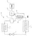
ここで図1および図2を参照すると、一実施形態では、冷凍システム1は、第1の熱交換器すなわち蒸発器4と流体連通している膨張弁2を含み得る。冷凍システム1には、圧縮機6が設けられている。圧縮機6は、第2の熱交換器すなわち凝縮器8と流体連通している。一実施形態では、圧縮機6は連続可変変速機(CVT)10に連結されている。CVT10は、原動機11から圧縮機6への速度および/またはトルクを変調するように構成することができる。実施形態によっては、CVT10は、第3の熱交換器12と流体連通している。CVT10には、潤滑システム14を設けることができる。潤滑システム14は、第3の熱交換器12に動作可能に連結することができる。冷凍システム1の動作中、CVT10によって発生した廃熱は、第3の熱交換器12を介して、冷凍システム1の冷媒などの作動流体に放出することができる。実施形態によっては、潤滑システム14は、圧縮機6の構成要素を冷却することができる。 Referring now to FIGS. 1 and 2, in one embodiment, the
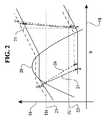
図2に示すものなどの温度エントロピ(T−s)図を使用して、冷凍システム1の動作を説明することができる。図の垂直軸16は、作動流体の温度を示す。水平軸18は、作動流体のエントロピを示す。曲線20は、周知の蒸気ドーム曲線であり、所与の作動流体を表す。作図線21、22は、一定温度の線を表す。説明のために、等温線21、22は、それらの間で冷凍サイクルが動作している2つの空間の温度、例えば車両の内部温度および周囲の外部温度に対応している。参考のため、一定のエントロピ23の作図線を図2の図に示す。 The operation of the
理想的な冷凍システムを示すため、代表的なサイクル24を実線でT−s線図に示す。例えば、冷凍システム1の動作を示すために、代表的なサイクル26を破線でT−s線図に示す。CVTからの廃熱は、冷媒に排出されることに留意されたい。図に示すように、システムに熱を加える影響として、蒸発器4の出口温度が上昇し得る(状態1、理想的な冷凍サイクルを「1」、および冷凍システム1を「1’」としてT−s線図に示す)。CVT10からの廃熱排出は、高い側の温度(状態2)に影響を及ぼす。冷凍システム1を動作させると、理想的な冷凍システムと比較して、システム内の圧力および温度を最終的に上昇させる新しい熱力学的平衡が達成される。低い側の蒸発器温度を、固定された低温側温度(例えば、作図線22で示す「TC」)に対して上昇させると、低温側から除去された熱量が減少し、それによって冷凍システムの性能係数に影響を及ぼす。 To show an ideal refrigeration system, a
次に図3〜図5を参照すると、一実施形態では、アイドラ34、第1のトラクションリング36および第2のトラクションリング38のそれぞれと接触する複数の球状トラクション遊星32を有するCVTに、スクロール圧縮機30を連結することができる。動力は、例えば駆動軸42に連結されたプーリ40を介して、CVTに伝達することができる。図3に示す実施形態などの一実施形態では、駆動軸42は、第1のトラクションリング36に動力を送る。トルクおよび/または速度は、トラクション遊星32を操作することよって変調することができ、かつ、スクロール圧縮機30に第2のトラクションリング38を動作可能に連結することによって、スクロール圧縮機30に伝達することができる。図4に示す実施形態などのいくつかの実施形態では、駆動軸42は、第2のトラクションリング38に動作可能に連結することができる。変調された動力は、第1のトラクションリング36を介して、スクロール圧縮機30に伝達することができる。図5に示す実施形態などの他の実施形態では、スクロール圧縮機30を、圧力チャンバ44に動作可能に連結することができる。CVTにスクロール圧縮機30を連結する実際の機械式実装は、様々な連続可変変速機を収容するように構成することができることに留意されたい。 3-5, in one embodiment, a CVT having a plurality of
次に図6を参照すると、一実施形態では、CVT50を、磁気クラッチ52に動作可能に連結することができる。磁気クラッチ52は、圧縮機シャフト54に動作可能に連結することができる。圧縮機シャフト54は、スクロール56に連結するように構成することができる。一実施形態では、共鳴室58を、スクロール56に動作可能に連結することができる。一実施形態では、CVT50は、米国特許出願第12/251,325号明細書に開示された連続可変変速機の実施形態に類似し得る。動力は、例えばエンジン(図示せず)から動力入力シャフト60を介して、CVT50に伝達することができる。トルクおよび/または速度は、複数の球状トラクション遊星アセンブリ62を操作することによって、CVT50を介して変調することができる。一実施形態では、トラクション遊星アセンブリ62は、第1のキャリア部材64を第2のキャリア部材66に対して相対的に回転させることによって、調節することができる。実施形態によっては、第1のキャリア部材64を第2のキャリア部材66に対して相対的に回転させることによって、トラクション遊星アセンブリ62のスキュー状態を調節し、それによってCVT50のトルクおよび/または速度の比の調節を容易にする。変調された動力は、出力動力シャフト68によって、CVT50から伝達することができる。出力動力シャフト68は、磁気クラッチ52に動作可能に連結することができる。 Referring now to FIG. 6, in one embodiment, the
次に図7を参照すると、一実施形態では、冷凍システム80は、凝縮器84、膨張弁86および蒸発器88を介して、冷媒などの作動流体を送出するように構成された圧縮機82を含み得る。圧縮機82は、CVT90に動作可能に連結することができる。CVT90は、例えば車両の原動機92に動作可能に連結することができる。一実施形態では、CVT90は、制御継手94に動作可能に連結されている。制御継手94は、CVT90の特定の構成要素を調節するように構成された機械式リンク機構または電気機械式リンク機構であり得、それによってCVT90の動作状態の変更を容易にする。一実施形態では、制御継手94は、図6に示す第1のキャリア部材64などの第1のキャリア部材に連結されたクレビス(clevis)(図示せず)である。実施形態によっては、冷凍システム80には、複動ピストン弁96を設けることができる。弁96は、ピストン98を有する。ピストン98は、制御継手94に動作可能に連結することができる。弁96は、ピストン98の一方の側に位置する第1のチャンバ97を有し得る。第1のチャンバ97は、冷凍システム80の低圧にさらされるように構成することができる。例えば、第1のチャンバ97は、蒸発器88の出口の冷媒の動作圧と同じ圧力を実質的に有し得る。弁96は、ピストン98の別の側に位置する第2のチャンバ99を有し得る。第2のチャンバ99は、冷凍システム80の高圧にさらされるように構成することができる。例えば、第2のチャンバ99は、凝縮器84の入口の冷媒の動作圧と同じ圧力を実質的に有し得る。他の実施形態では、ピストン98を中立位置に戻し、またはピストン98の予め設定された位置を与えるために、ピストン98をバネ(図示せず)に連結することができる。さらに他の実施形態では、ピストン98を中立位置に戻し、またはピストン98の予め設定された位置を与えるために、ピストン98を負圧室(図示せず)に動作可能に連結することができる。 Referring now to FIG. 7, in one embodiment, the
冷凍システム80の動作中、第1のチャンバ97と第2のチャンバ99との間に発生した差圧は、弁96内のピストン98の変位を生成し得る。ピストン98の変位は、制御継手94を介して移動させ、CVT90の動作状態の変更を容易にする。第1のチャンバ97と第2のチャンバ99との間に発生した差圧は、冷凍システム80内の冷媒の熱力学状態によって発生することに留意されたい。 During operation of the
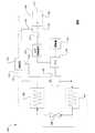
次に図8を参照すると、一実施形態では、冷凍システム100は、凝縮器104、膨張弁106および蒸発器108を介して冷媒を送出するように構成された圧縮機102を有し得る。圧縮機102は、CVT110に動作可能に連結することができる。CVT110は、原動機111から圧縮機102へのトルクおよび/または速度を変調することができる。一実施形態では、CVT110は、CVT制御継手112に動作可能に連結されている。CVT制御継手112は、CVT110の特定の構成要素を調節するように構成された機械式リンク機構または電気機械式リンク機構であり得る。冷凍システム100には、ピストン115を有する複動ピストン弁114を設けることができる。弁114は、CVT制御継手112に連結することができる。一実施形態では、冷凍システム100には、制御弁116が設けられている。制御弁116は、弁114と流体連通している。実施形態によっては、制御弁116は、圧縮機102の入口側の圧力117と、圧縮機102の出口側の圧力118とを検知するように構成されている。言いかえれば、制御弁116は、冷凍システム100の差圧を検知することができる。実施形態によっては、制御弁116は、圧縮機102から信号119を受け取るように構成することができる。制御弁116は、弁114の第1のチャンバ121に第1の制御圧力120を供給することができる。制御弁116は、弁114の第2のチャンバ123に第2の制御圧力122を供給することができる。実施形態によっては、制御弁116は、さらに油圧アキュムレータ(図示せず)に連結することができる。アキュムレータは、圧縮機102からの起こり得る高圧放出を管理し、かつCVT110の滑りを防ぐために、使用することができる。他の実施形態では、制御弁114は、動作中、負荷に基づいた軸方向の力を供給するために、CVT110(図示せず)の軸力生成構成要素に連結することができる。 Referring now to FIG. 8, in one embodiment, the
冷凍システム100の動作中、圧縮機102全体にわたって発生した差圧は、制御弁116を介して弁114に伝えることができる。第1のチャンバ121と第2のチャンバ123との間に発生した差圧は、ピストン115の変位を生成し得る。ピストン115の変位は、CVT制御継手112によってCVT110に移動させることができ、それによってCVT110の動作状態の変更を容易にする。実施形態によっては、制御弁116により、第1のチャンバ121と第2のチャンバ123との間の圧力差の大きさが、圧縮機102全体にわたる圧力差の大きさと異なり得ることに留意されたい。 During operation of the
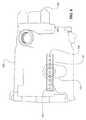
次に図9を参照すると、一実施形態では、実質的に閉じたハウジング130を、例えば、とりわけ冷凍システム用のスクロール圧縮機を支持するために使用することができる。ハウジング130には、吸込口132および吐出口138が設けられている。吸込口132および吐出口138は、典型的には圧縮機の中、および圧縮機の外に、R134Aなどの冷媒を送る。ハウジング130には、複数の穴部またはチャンネル136を有するアダプタプレート134を備えることができる。アダプタプレート134は、冷媒流が圧縮機スクロールおよびCVTの全体に広がることを可能にする吸込口132への接続を行う。チャンネル136は、アダプタプレート134の一方の端部で収束し得る。例えば、チャンネル136の収束は、吸込口132に近接し得る。チャンネル136は、アダプタプレート134の他方の端部で分岐し得る。一実施形態では、アダプタプレート134は、ハウジング130の内部に位置する。冷媒の流れは、ハウジング130内の圧縮機構成要素およびCVT構成要素を冷却する。 Referring now to FIG. 9, in one embodiment, the substantially closed housing 130 can be used, for example, to support a scroll compressor, particularly for a refrigeration system. The housing 130 is provided with a
上記の説明では、特定の構成要素またはサブアセンブリに寸法を提供したことに留意されたい。最良のモードなどの、特定の法的要件に可能な限り最善に準拠するため、記載した寸法または寸法の範囲を提供する。しかしながら、本明細書で説明した実施形態の範囲は、特許請求の範囲の文言によってのみ決定されるべきであり、したがって、いずれか1つの特許請求の範囲が特定の寸法、またはその範囲、特許請求の範囲の特徴を示さない限り、記述した寸法のいずれも、本発明の実施形態に対する限定と考えられるべきではない。 It should be noted that the above description provided dimensions for particular components or subassemblies. Provide the stated dimensions or range of dimensions to best comply with specific legal requirements, such as best mode. However, the scope of the embodiments described herein should be determined only by the language of the claims, and thus any one claim is a specific dimension, or its range, claim. None of the dimensions described should be considered a limitation on the embodiments of the present invention unless otherwise indicated.
先の記述は、本開示の特定の実施形態を詳述している。しかしながら、文中の先の記述がどれほど詳細であっても、本開示は多くの方法で実施することができることが理解されるであろう。上でも述べているように、本開示の特定の特徴または態様について記述する場合に特定の用語を使用することは、その用語が関連している本開示の特徴または態様の任意の特定の特性を含むように限定するために、用語を本明細書で再定義していることを示唆するものととられるべきではないことに留意されたい。 The foregoing description details certain embodiments of the disclosure. However, it will be understood that no matter how detailed the foregoing description is, the present disclosure can be implemented in many ways. As noted above, the use of a particular term when describing a particular feature or aspect of the present disclosure refers to any particular characteristic of the feature or aspect of the present disclosure to which that term relates. It should be noted that the terminology should not be taken to imply re-defining terms herein for the purpose of limiting inclusion.
Claims (24)
Translated fromJapanese前記蒸発器、前記膨張弁および前記凝縮器と流体連通している圧縮機と、
前記圧縮機に動作可能に連結された連続可変変速機(CVT)であって、前記圧縮機に動力入力を行うように構成されたCVTと、
前記CVTの内部構成要素に動作可能に連結されたCVT冷却システムであって、前記圧縮機、前記蒸発器、前記膨張弁および前記凝縮器と流体連通しているCVT冷却システムと
を含む冷凍システム。A refrigeration system having an evaporator, an expansion valve and a condenser,
A compressor in fluid communication with the evaporator, the expansion valve and the condenser;
A continuously variable transmission (CVT) operably coupled to the compressor, the CVT configured to provide power input to the compressor;
A refrigeration system operatively coupled to internal components of the CVT, the CVT cooling system in fluid communication with the compressor, the evaporator, the expansion valve, and the condenser.
前記圧縮機に連結され、前記圧縮機に入力動力を供給するように構成された連続可変変速機(CVT)と、
前記CVTに動作可能に連結された冷却システムと、
を含み、
前記冷却システムが、前記冷媒と熱連通している
冷凍システム。A refrigeration system having an evaporator, an expansion valve, a compressor and a condenser, each hydraulically connected to a refrigerant,
A continuously variable transmission (CVT) coupled to the compressor and configured to provide input power to the compressor;
A cooling system operably coupled to the CVT;
Including
A refrigeration system in which the cooling system is in thermal communication with the refrigerant.
前記CVTが、
前記長手軸の周りに角度をつけて配置された複数の球状トラクション遊星と、
各トラクション遊星に動作可能に連結された第1のキャリア部材であって、半径方向にオフセットされた複数のガイドスロットが設けられた第1のキャリア部材と、
各トラクション遊星に動作可能に連結された第2のキャリア部材であって、半径方向の複数のガイドスロットが設けられた第2のキャリア部材と
を含み、
前記第1のキャリア部材を、前記第2のキャリア部材に対して回転させることができ、それによって前記CVTの動作状態の変更を容易にする、
請求項8に記載の冷凍システム。The CVT has a longitudinal axis;
The CVT is
A plurality of spherical traction planets arranged at an angle around the longitudinal axis;
A first carrier member operably coupled to each traction planet, wherein the first carrier member is provided with a plurality of radially offset guide slots;
A second carrier member operably coupled to each traction planet, wherein the second carrier member is provided with a plurality of radial guide slots;
The first carrier member can be rotated relative to the second carrier member, thereby facilitating a change in the operating state of the CVT;
The refrigeration system according to claim 8.
前記CVTに連結された油圧ピストンと、
前記油圧ピストンと流体連通している油圧制御弁と、
前記油圧制御弁に連結されたスプールアクチュエータであって、前記CVTの動作状態に少なくとも部分的に基づいて前記油圧制御弁を調節するように構成されたスプールアクチュエータと
を含み、
前記油圧ピストン、前記油圧制御弁および前記スプールアクチュエータが、冷凍システムの作動流体に油圧的に連結している
アクチュエータ。Actuators for a continuously variable transmission (CVT) each having a plurality of spherical traction planets supported by a first carrier member and a second carrier member, wherein the first carrier member is an operation of the CVT An actuator configured to rotate relative to the second carrier member to facilitate a change in state;
A hydraulic piston coupled to the CVT;
A hydraulic control valve in fluid communication with the hydraulic piston;
A spool actuator coupled to the hydraulic control valve, the spool actuator configured to adjust the hydraulic control valve based at least in part on an operating state of the CVT;
An actuator in which the hydraulic piston, the hydraulic control valve, and the spool actuator are hydraulically coupled to a working fluid of a refrigeration system.
前記圧縮機の速度を変更するように構成され、かつ変速機流体システムを有するCVTを設けるステップと、
前記CVTの伝達比を変更することによって、前記圧縮機の動作速度を変更するステップと、
前記変速機流体システムから前記冷媒へ熱を伝達するステップと
を含む方法。A method for improving the performance of a refrigeration system having a compressor, a condenser, an evaporator, and a refrigerant comprising:
Providing a CVT configured to change a speed of the compressor and having a transmission fluid system;
Changing the operating speed of the compressor by changing the transmission ratio of the CVT;
Transferring heat from the transmission fluid system to the refrigerant.
第1の温度の環境にさらされている第1の熱交換器を設けるステップと、
膨張弁に前記第1の熱交換器を連結するステップと、
第2の温度の環境にさらされている第2の熱交換器を設けるステップと、
前記膨張弁に前記第2の熱交換器を連結するステップと、
圧縮機を設けるステップと、
前記第1の熱交換器および前記第2の熱交換器と、前記膨張弁との間に作動流体を送出するように前記圧縮機を構成するステップと、
前記圧縮機に連続可変変速機(CVT)を連結するステップと
を含み、
前記CVTが、前記作動流体の状態の変化に少なくとも部分的に基づいて動作状態を変更するように構成されている
方法。A method of manufacturing a refrigeration system comprising:
Providing a first heat exchanger that is exposed to a first temperature environment;
Connecting the first heat exchanger to an expansion valve;
Providing a second heat exchanger that is exposed to a second temperature environment;
Connecting the second heat exchanger to the expansion valve;
Providing a compressor; and
Configuring the compressor to deliver a working fluid between the first heat exchanger and the second heat exchanger and the expansion valve;
Connecting a continuously variable transmission (CVT) to the compressor,
The method wherein the CVT is configured to change an operating state based at least in part on a change in the state of the working fluid.
第1の温度の環境にさらされている第1の熱交換器を設けるステップと、
膨張弁に前記第1の熱交換器を連結するステップと、
第2の温度の環境にさらされている第2の熱交換器を設けるステップと、
前記膨張弁に前記第2の熱交換器を連結するステップと、
圧縮機を設けるステップと、
前記第1の熱交換器および前記第2の熱交換器と、前記膨張弁との間に作動流体を送出するように前記圧縮機を構成するステップと、
前記圧縮機に連続可変変速機(CVT)を連結するステップと
前記CVTの内部構成要素に動作可能に連結された第3の熱交換器を設けるステップと、
前記作動流体に前記第3の熱交換器を油圧的に連結し、それによって前記作動流体が、前記CVTの前記内部構成要素からの廃熱にさらされるステップと
を含む方法。A method of manufacturing a refrigeration system comprising:
Providing a first heat exchanger that is exposed to a first temperature environment;
Connecting the first heat exchanger to an expansion valve;
Providing a second heat exchanger that is exposed to a second temperature environment;
Connecting the second heat exchanger to the expansion valve;
Providing a compressor; and
Configuring the compressor to deliver a working fluid between the first heat exchanger and the second heat exchanger and the expansion valve;
Coupling a continuously variable transmission (CVT) to the compressor; providing a third heat exchanger operatively coupled to internal components of the CVT;
Hydraulically coupling the third heat exchanger to the working fluid, whereby the working fluid is exposed to waste heat from the internal components of the CVT.
Applications Claiming Priority (3)
| Application Number | Priority Date | Filing Date | Title |
|---|---|---|---|
| US201161542708P | 2011-10-03 | 2011-10-03 | |
| US61/542,708 | 2011-10-03 | ||
| PCT/US2012/058334WO2013052425A2 (en) | 2011-10-03 | 2012-10-01 | Refrigeration system having a continuously variable transmission |
Publications (1)
| Publication Number | Publication Date |
|---|---|
| JP2014528564Atrue JP2014528564A (en) | 2014-10-27 |
Family
ID=47049364
Family Applications (1)
| Application Number | Title | Priority Date | Filing Date |
|---|---|---|---|
| JP2014533479APendingJP2014528564A (en) | 2011-10-03 | 2012-10-01 | Refrigeration system with continuously variable transmission |
Country Status (8)
| Country | Link |
|---|---|
| US (1) | US20130139531A1 (en) |
| EP (1) | EP2764305A2 (en) |
| JP (1) | JP2014528564A (en) |
| CN (1) | CN103958989A (en) |
| CA (1) | CA2850224A1 (en) |
| RU (1) | RU2014114186A (en) |
| TW (1) | TW201337131A (en) |
| WO (1) | WO2013052425A2 (en) |
Families Citing this family (10)
| Publication number | Priority date | Publication date | Assignee | Title |
|---|---|---|---|---|
| CN102221073B (en) | 2005-12-09 | 2013-03-27 | 福博科技术公司 | Continuously variable transmission |
| EP1811202A1 (en) | 2005-12-30 | 2007-07-25 | Fallbrook Technologies, Inc. | A continuously variable gear transmission |
| CN103939602B (en) | 2007-11-16 | 2016-12-07 | 福博科知识产权有限责任公司 | Controllers for variable speed drives |
| US10047861B2 (en) | 2016-01-15 | 2018-08-14 | Fallbrook Intellectual Property Company Llc | Systems and methods for controlling rollback in continuously variable transmissions |
| US10023266B2 (en) | 2016-05-11 | 2018-07-17 | Fallbrook Intellectual Property Company Llc | Systems and methods for automatic configuration and automatic calibration of continuously variable transmissions and bicycles having continuously variable transmissions |
| CN106763738B (en)* | 2016-12-26 | 2018-05-29 | 王军辉 | A kind of hydraulic continuously variable transmission |
| JP6753379B2 (en)* | 2017-09-15 | 2020-09-09 | トヨタ自動車株式会社 | Vehicle heat exchange system |
| US11215268B2 (en) | 2018-11-06 | 2022-01-04 | Fallbrook Intellectual Property Company Llc | Continuously variable transmissions, synchronous shifting, twin countershafts and methods for control of same |
| US10962294B2 (en) | 2018-12-07 | 2021-03-30 | Hamilton Sundstrand Corporation | Dual pass heat exchanger with drain system |
| WO2020176392A1 (en) | 2019-02-26 | 2020-09-03 | Fallbrook Intellectual Property Company Llc | Reversible variable drives and systems and methods for control in forward and reverse directions |
Family Cites Families (33)
| Publication number | Priority date | Publication date | Assignee | Title |
|---|---|---|---|---|
| US1807774A (en)* | 1931-06-02 | Automatic refrigeration | ||
| US2469653A (en) | 1945-02-01 | 1949-05-10 | Kopp Jean | Stepless variable change-speed gear with roller bodies |
| US2901924A (en)* | 1954-08-05 | 1959-09-01 | New Prod Corp | Accessory drive |
| US3010289A (en)* | 1959-04-14 | 1961-11-28 | Carrier Corp | Refrigeration system with variable speed compressor |
| US4065229A (en)* | 1976-10-01 | 1977-12-27 | General Motors Corporation | Variable capacity radial-4 compressor |
| US4257795A (en)* | 1978-04-06 | 1981-03-24 | Dunham-Bush, Inc. | Compressor heat pump system with maximum and minimum evaporator ΔT control |
| US4501172A (en)* | 1982-08-16 | 1985-02-26 | Excelermatic Inc. | Hydraulic speed control arrangement for an infinitely variable transmission |
| US4744261A (en) | 1985-11-27 | 1988-05-17 | Honeywell Inc. | Ball coupled compound traction drive |
| US4830578A (en)* | 1987-10-26 | 1989-05-16 | Excelermatic Inc. | Hydraulic control arrangement for an infinitely variable transmission drive |
| DE4127030A1 (en) | 1991-08-16 | 1993-02-18 | Fichtel & Sachs Ag | DRIVE HUB WITH CONTINUOUSLY ADJUSTABLE GEAR RATIO |
| DE4126993A1 (en)* | 1991-08-16 | 1993-02-18 | Fichtel & Sachs Ag | Drive hub for a vehicle, especially a bicycle, with a continuously variable transmission ratio. |
| EP0842799A3 (en)* | 1996-11-15 | 2003-03-05 | Calsonic Kansei Corporation | Heat pump type air conditioning system for automotive vehicle |
| US6419608B1 (en) | 1999-10-22 | 2002-07-16 | Motion Technologies, Llc | Continuously variable transmission |
| US6241636B1 (en) | 1997-09-02 | 2001-06-05 | Motion Technologies, Llc | Continuously variable transmission |
| US5918476A (en)* | 1997-11-20 | 1999-07-06 | Cowart; Darrow W. | Replacement kit for vehicle air conditioning circuit pressure operable valves |
| JP2001082566A (en) | 1999-09-14 | 2001-03-27 | Nsk Ltd | Toroidal continuously variable transmission |
| JP3942836B2 (en)* | 2001-03-09 | 2007-07-11 | ジヤトコ株式会社 | Hydraulic oil cooling device for automatic transmission for vehicle |
| KR100854795B1 (en) | 2001-04-26 | 2008-08-27 | 모션 테크놀로지즈 엘엘씨 | Device for speed ratio adjustment of roller traction transmission and continuous variable transmission |
| US6434960B1 (en)* | 2001-07-02 | 2002-08-20 | Carrier Corporation | Variable speed drive chiller system |
| GB0121739D0 (en) | 2001-09-08 | 2001-10-31 | Milner Peter J | An improved continuously variable transmission |
| US6698234B2 (en)* | 2002-03-20 | 2004-03-02 | Carrier Corporation | Method for increasing efficiency of a vapor compression system by evaporator heating |
| US6651451B2 (en)* | 2002-04-23 | 2003-11-25 | Vai Holdings, Llc | Variable capacity refrigeration system with a single-frequency compressor |
| US7011600B2 (en) | 2003-02-28 | 2006-03-14 | Fallbrook Technologies Inc. | Continuously variable transmission |
| US7028475B2 (en)* | 2003-05-20 | 2006-04-18 | Denso Corporation | Fluid machine |
| GB0315408D0 (en) | 2003-07-01 | 2003-08-06 | Torotrak Dev Ltd | Continuously variable ratio transmission system |
| US7166052B2 (en) | 2003-08-11 | 2007-01-23 | Fallbrook Technologies Inc. | Continuously variable planetary gear set |
| US7086981B2 (en) | 2004-02-18 | 2006-08-08 | The Gates Corporation | Transmission and constant speed accessory drive |
| JP2005307835A (en)* | 2004-04-20 | 2005-11-04 | Toyota Industries Corp | Compressor with transmission |
| CN103697120B (en)* | 2007-07-05 | 2017-04-12 | 福博科技术公司 | Continuously variable transmission |
| US8424337B2 (en)* | 2008-01-17 | 2013-04-23 | Carrier Corporation | Refrigerant vapor compression system with lubricant cooler |
| US8590324B2 (en)* | 2009-05-15 | 2013-11-26 | Emerson Climate Technologies, Inc. | Compressor and oil-cooling system |
| US9080797B2 (en)* | 2009-05-19 | 2015-07-14 | Carrier Corporation | Variable speed compressor |
| US8512195B2 (en)* | 2010-03-03 | 2013-08-20 | Fallbrook Intellectual Property Company Llc | Infinitely variable transmissions, continuously variable transmissions, methods, assemblies, subassemblies, and components therefor |
- 2012
- 2012-10-01EPEP12775578.3Apatent/EP2764305A2/ennot_activeWithdrawn
- 2012-10-01RURU2014114186/11Apatent/RU2014114186A/ennot_activeApplication Discontinuation
- 2012-10-01WOPCT/US2012/058334patent/WO2013052425A2/enactiveApplication Filing
- 2012-10-01CACA2850224Apatent/CA2850224A1/ennot_activeAbandoned
- 2012-10-01CNCN201280048655.5Apatent/CN103958989A/enactivePending
- 2012-10-01JPJP2014533479Apatent/JP2014528564A/enactivePending
- 2012-10-02TWTW101136419Apatent/TW201337131A/enunknown
- 2012-10-02USUS13/633,474patent/US20130139531A1/ennot_activeAbandoned
Also Published As
| Publication number | Publication date |
|---|---|
| CN103958989A (en) | 2014-07-30 |
| TW201337131A (en) | 2013-09-16 |
| WO2013052425A3 (en) | 2014-05-08 |
| RU2014114186A (en) | 2015-11-10 |
| CA2850224A1 (en) | 2013-04-11 |
| US20130139531A1 (en) | 2013-06-06 |
| EP2764305A2 (en) | 2014-08-13 |
| WO2013052425A2 (en) | 2013-04-11 |
Similar Documents
| Publication | Publication Date | Title |
|---|---|---|
| JP2014528564A (en) | Refrigeration system with continuously variable transmission | |
| US10197147B2 (en) | Continuously variable transmission | |
| US7261195B2 (en) | Power transfer devices with on-demand lubrication systems | |
| US20040237681A1 (en) | Powertrain control | |
| JP2001227616A (en) | Drive | |
| JP2010236693A (en) | Hydraulic control device for automatic transmission | |
| WO2008130059A1 (en) | Hydraulic control device | |
| CN103477120B (en) | Variable v-belt drive | |
| US5871412A (en) | Technical field | |
| US9562594B2 (en) | Variator multiplex valve scheme for a torroidal traction drive transmission | |
| US20160084124A1 (en) | Hybrid Oil Pump System and Method of Controlling the Same | |
| CN115717646A (en) | Transmission hydraulic system and method for operating a hydraulic system | |
| JP2011202709A (en) | Check valve | |
| JP5559884B2 (en) | Vehicle transmission | |
| JP2020535366A (en) | Fluid system with accumulator for disc set pressing in continuously variable transmission and continuously variable transmission | |
| JP4935343B2 (en) | Hydraulic control device for continuously variable transmission | |
| JP4978185B2 (en) | Hydraulic control device for continuously variable transmission | |
| JP2013113431A (en) | Driving force transmission device | |
| US7237665B2 (en) | Thermal energy transfer limited rotating shaft for a pneumatic fan drive system | |
| US6789654B2 (en) | Multiple coupling fan drive | |
| JP3609293B2 (en) | Diesel vehicle accessory drive system | |
| CN116971856A (en) | Cooling and lubricating system and vehicle with same | |
| JP2008045401A (en) | Refrigerant compressor for air conditioner | |
| JP2010164094A (en) | Vehicle driving device | |
| JPH03980A (en) | Refrigerant compressor with fluid coupling |
Legal Events
| Date | Code | Title | Description |
|---|---|---|---|
| RD03 | Notification of appointment of power of attorney | Free format text:JAPANESE INTERMEDIATE CODE: A7423 Effective date:20150105 | |
| RD04 | Notification of resignation of power of attorney | Free format text:JAPANESE INTERMEDIATE CODE: A7424 Effective date:20150320 |