JP2014528286A - Pressure wave root canal cleaning system - Google Patents
Pressure wave root canal cleaning systemDownload PDFInfo
- Publication number
- JP2014528286A JP2014528286AJP2014533478AJP2014533478AJP2014528286AJP 2014528286 AJP2014528286 AJP 2014528286AJP 2014533478 AJP2014533478 AJP 2014533478AJP 2014533478 AJP2014533478 AJP 2014533478AJP 2014528286 AJP2014528286 AJP 2014528286A
- Authority
- JP
- Japan
- Prior art keywords
- fluid
- electromagnetic radiation
- bubbles
- target area
- interaction zone
- Prior art date
- Legal status (The legal status is an assumption and is not a legal conclusion. Google has not performed a legal analysis and makes no representation as to the accuracy of the status listed.)
- Pending
Links
- 238000004140cleaningMethods0.000titleclaimsabstractdescription40
- 210000004262dental pulp cavityAnatomy0.000titleclaimsdescription16
- 239000012530fluidSubstances0.000claimsabstractdescription173
- 230000005670electromagnetic radiationEffects0.000claimsabstractdescription71
- 238000000034methodMethods0.000claimsabstractdescription49
- 230000003993interactionEffects0.000claimsabstractdescription41
- 230000033001locomotionEffects0.000claimsabstractdescription29
- 230000001954sterilising effectEffects0.000claimsabstractdescription26
- 206010068150Acoustic shockDiseases0.000claimsabstractdescription21
- 230000000694effectsEffects0.000claimsabstractdescription10
- 239000000835fiberSubstances0.000claimsdescription59
- 241000894006BacteriaSpecies0.000claimsdescription35
- 239000013307optical fiberSubstances0.000claimsdescription26
- CURLTUGMZLYLDI-UHFFFAOYSA-NCarbon dioxideChemical compoundO=C=OCURLTUGMZLYLDI-UHFFFAOYSA-N0.000claimsdescription10
- 239000000203mixtureSubstances0.000claimsdescription9
- IJGRMHOSHXDMSA-UHFFFAOYSA-NAtomic nitrogenChemical compoundN#NIJGRMHOSHXDMSA-UHFFFAOYSA-N0.000claimsdescription8
- 238000004659sterilization and disinfectionMethods0.000claimsdescription8
- 238000011282treatmentMethods0.000claimsdescription8
- 238000010521absorption reactionMethods0.000claimsdescription7
- 230000006835compressionEffects0.000claimsdescription7
- 238000007906compressionMethods0.000claimsdescription7
- 239000002360explosiveSubstances0.000claimsdescription6
- 239000002223garnetSubstances0.000claimsdescription6
- 229910052691ErbiumInorganic materials0.000claimsdescription5
- 229910002092carbon dioxideInorganic materials0.000claimsdescription5
- 239000001569carbon dioxideSubstances0.000claimsdescription5
- UYAHIZSMUZPPFV-UHFFFAOYSA-NerbiumChemical compound[Er]UYAHIZSMUZPPFV-UHFFFAOYSA-N0.000claimsdescription5
- ZCYVEMRRCGMTRW-UHFFFAOYSA-N7553-56-2Chemical compound[I]ZCYVEMRRCGMTRW-UHFFFAOYSA-N0.000claimsdescription4
- 239000003899bactericide agentSubstances0.000claimsdescription4
- 210000004204blood vesselAnatomy0.000claimsdescription4
- 239000003814drugSubstances0.000claimsdescription4
- 229940079593drugDrugs0.000claimsdescription4
- 239000011630iodineSubstances0.000claimsdescription4
- 229910052740iodineInorganic materials0.000claimsdescription4
- 239000002105nanoparticleSubstances0.000claimsdescription4
- 229910052757nitrogenInorganic materials0.000claimsdescription4
- TWNQGVIAIRXVLR-UHFFFAOYSA-Noxo(oxoalumanyloxy)alumaneChemical groupO=[Al]O[Al]=OTWNQGVIAIRXVLR-UHFFFAOYSA-N0.000claimsdescription4
- 239000002245particleSubstances0.000claimsdescription4
- VYZAMTAEIAYCRO-UHFFFAOYSA-NChromiumChemical compound[Cr]VYZAMTAEIAYCRO-UHFFFAOYSA-N0.000claimsdescription3
- 239000003242anti bacterial agentSubstances0.000claimsdescription3
- 230000000844anti-bacterial effectEffects0.000claimsdescription3
- 229940088710antibiotic agentDrugs0.000claimsdescription3
- 229910052804chromiumInorganic materials0.000claimsdescription3
- 239000011651chromiumSubstances0.000claimsdescription3
- GYHNNYVSQQEPJS-UHFFFAOYSA-NGalliumChemical compound[Ga]GYHNNYVSQQEPJS-UHFFFAOYSA-N0.000claimsdescription2
- 230000000975bioactive effectEffects0.000claimsdescription2
- 239000003795chemical substances by applicationSubstances0.000claimsdescription2
- 208000002925dental cariesDiseases0.000claimsdescription2
- 229910052733galliumInorganic materials0.000claimsdescription2
- 239000000843powderSubstances0.000claimsdescription2
- 210000005239tubuleAnatomy0.000claimsdescription2
- MOCSSSMOHPPNTG-UHFFFAOYSA-N[Sc].[Y]Chemical compound[Sc].[Y]MOCSSSMOHPPNTG-UHFFFAOYSA-N0.000claims1
- 239000003082abrasive agentSubstances0.000claims1
- 238000010586diagramMethods0.000description12
- 239000007788liquidSubstances0.000description10
- 239000007789gasSubstances0.000description6
- 239000000463materialSubstances0.000description6
- 239000007787solidSubstances0.000description6
- 229910052727yttriumInorganic materials0.000description6
- VWQVUPCCIRVNHF-UHFFFAOYSA-Nyttrium atomChemical compound[Y]VWQVUPCCIRVNHF-UHFFFAOYSA-N0.000description6
- 238000005253claddingMethods0.000description5
- 229910052782aluminiumInorganic materials0.000description4
- XAGFODPZIPBFFR-UHFFFAOYSA-NaluminiumChemical compound[Al]XAGFODPZIPBFFR-UHFFFAOYSA-N0.000description4
- 210000004027cellAnatomy0.000description3
- 238000007726management methodMethods0.000description3
- 230000003287optical effectEffects0.000description3
- 230000005855radiationEffects0.000description3
- VYPSYNLAJGMNEJ-UHFFFAOYSA-Nsilicon dioxideInorganic materialsO=[Si]=OVYPSYNLAJGMNEJ-UHFFFAOYSA-N0.000description3
- 210000001519tissueAnatomy0.000description3
- 241000282412HomoSpecies0.000description2
- 241001465754MetazoaSpecies0.000description2
- CDBYLPFSWZWCQE-UHFFFAOYSA-LSodium CarbonateChemical compound[Na+].[Na+].[O-]C([O-])=OCDBYLPFSWZWCQE-UHFFFAOYSA-L0.000description2
- 239000000853adhesiveSubstances0.000description2
- 230000001070adhesive effectEffects0.000description2
- UCTWMZQNUQWSLP-UHFFFAOYSA-NadrenalineChemical compoundCNCC(O)C1=CC=C(O)C(O)=C1UCTWMZQNUQWSLP-UHFFFAOYSA-N0.000description2
- 235000013405beerNutrition0.000description2
- 239000012620biological materialSubstances0.000description2
- 235000012174carbonated soft drinkNutrition0.000description2
- 235000019993champagneNutrition0.000description2
- 239000000356contaminantSubstances0.000description2
- 239000000645desinfectantSubstances0.000description2
- 230000001066destructive effectEffects0.000description2
- 239000000428dustSubstances0.000description2
- 238000010304firingMethods0.000description2
- 208000015181infectious diseaseDiseases0.000description2
- 238000012986modificationMethods0.000description2
- 230000004048modificationEffects0.000description2
- 239000002086nanomaterialSubstances0.000description2
- 239000013618particulate matterSubstances0.000description2
- -1residueSubstances0.000description2
- XLYOFNOQVPJJNP-UHFFFAOYSA-NwaterSubstancesOXLYOFNOQVPJJNP-UHFFFAOYSA-N0.000description2
- UCTWMZQNUQWSLP-VIFPVBQESA-N(R)-adrenalineChemical compoundCNC[C@H](O)C1=CC=C(O)C(O)=C1UCTWMZQNUQWSLP-VIFPVBQESA-N0.000description1
- 229930182837(R)-adrenalineNatural products0.000description1
- 208000002874Acne VulgarisDiseases0.000description1
- OKTJSMMVPCPJKN-UHFFFAOYSA-NCarbonChemical compound[C]OKTJSMMVPCPJKN-UHFFFAOYSA-N0.000description1
- 102000029749MicrotubuleHuman genes0.000description1
- 108091022875MicrotubuleProteins0.000description1
- 229910052779NeodymiumInorganic materials0.000description1
- 229910052775ThuliumInorganic materials0.000description1
- VZPPHXVFMVZRTE-UHFFFAOYSA-N[Kr]FChemical compound[Kr]FVZPPHXVFMVZRTE-UHFFFAOYSA-N0.000description1
- 206010000496acneDiseases0.000description1
- 230000009471actionEffects0.000description1
- 210000003484anatomyAnatomy0.000description1
- 229940035674anestheticsDrugs0.000description1
- 230000003110anti-inflammatory effectEffects0.000description1
- 239000007864aqueous solutionSubstances0.000description1
- ISQINHMJILFLAQ-UHFFFAOYSA-Nargon hydrofluorideChemical compoundF.[Ar]ISQINHMJILFLAQ-UHFFFAOYSA-N0.000description1
- 210000001367arteryAnatomy0.000description1
- 230000001580bacterial effectEffects0.000description1
- 210000000988bone and boneAnatomy0.000description1
- 229910052799carbonInorganic materials0.000description1
- 210000000170cell membraneAnatomy0.000description1
- 230000008859changeEffects0.000description1
- 238000001804debridementMethods0.000description1
- 230000007423decreaseEffects0.000description1
- 210000004268dentinAnatomy0.000description1
- 230000008021depositionEffects0.000description1
- 201000010099diseaseDiseases0.000description1
- 208000037265diseases, disorders, signs and symptomsDiseases0.000description1
- 238000006073displacement reactionMethods0.000description1
- 229960005139epinephrineDrugs0.000description1
- 239000006260foamSubstances0.000description1
- 239000003193general anesthetic agentSubstances0.000description1
- YBMRDBCBODYGJE-UHFFFAOYSA-Ngermanium oxideInorganic materialsO=[Ge]=OYBMRDBCBODYGJE-UHFFFAOYSA-N0.000description1
- 239000011521glassSubstances0.000description1
- 230000036541healthEffects0.000description1
- 210000002216heartAnatomy0.000description1
- 235000008216herbsNutrition0.000description1
- 229910052500inorganic mineralInorganic materials0.000description1
- 230000001788irregularEffects0.000description1
- 210000003734kidneyAnatomy0.000description1
- 210000004072lungAnatomy0.000description1
- 238000004519manufacturing processMethods0.000description1
- 239000011159matrix materialSubstances0.000description1
- 238000004377microelectronicMethods0.000description1
- 210000004688microtubuleAnatomy0.000description1
- 239000011707mineralSubstances0.000description1
- 235000010755mineralNutrition0.000description1
- 230000001338necrotic effectEffects0.000description1
- QEFYFXOXNSNQGX-UHFFFAOYSA-Nneodymium atomChemical compound[Nd]QEFYFXOXNSNQGX-UHFFFAOYSA-N0.000description1
- 210000000056organAnatomy0.000description1
- PVADDRMAFCOOPC-UHFFFAOYSA-NoxogermaniumChemical compound[Ge]=OPVADDRMAFCOOPC-UHFFFAOYSA-N0.000description1
- 239000002504physiological saline solutionSubstances0.000description1
- 230000008569processEffects0.000description1
- 239000002096quantum dotSubstances0.000description1
- 239000010453quartzSubstances0.000description1
- 230000004044responseEffects0.000description1
- 229910052594sapphireInorganic materials0.000description1
- 239000010980sapphireSubstances0.000description1
- 229910052706scandiumInorganic materials0.000description1
- SIXSYDAISGFNSX-UHFFFAOYSA-Nscandium atomChemical compound[Sc]SIXSYDAISGFNSX-UHFFFAOYSA-N0.000description1
- 210000004872soft tissueAnatomy0.000description1
- 239000002689soilSubstances0.000description1
- 210000000952spleenAnatomy0.000description1
- 239000003206sterilizing agentSubstances0.000description1
- 150000003431steroidsChemical class0.000description1
- 239000000126substanceSubstances0.000description1
- 238000001356surgical procedureMethods0.000description1
- 208000024891symptomDiseases0.000description1
- 229940088594vitaminDrugs0.000description1
- 239000011782vitaminSubstances0.000description1
- 229930003231vitaminNatural products0.000description1
- 235000013343vitaminNutrition0.000description1
- 238000005406washingMethods0.000description1
- HGCGQDMQKGRJNO-UHFFFAOYSA-Nxenon monochlorideChemical compound[Xe]ClHGCGQDMQKGRJNO-UHFFFAOYSA-N0.000description1
Images


Classifications
- A—HUMAN NECESSITIES
- A61—MEDICAL OR VETERINARY SCIENCE; HYGIENE
- A61C—DENTISTRY; APPARATUS OR METHODS FOR ORAL OR DENTAL HYGIENE
- A61C17/00—Devices for cleaning, polishing, rinsing or drying teeth, teeth cavities or prostheses; Saliva removers; Dental appliances for receiving spittle
- A61C17/02—Rinsing or air-blowing devices, e.g. using fluid jets or comprising liquid medication
- A—HUMAN NECESSITIES
- A61—MEDICAL OR VETERINARY SCIENCE; HYGIENE
- A61C—DENTISTRY; APPARATUS OR METHODS FOR ORAL OR DENTAL HYGIENE
- A61C1/00—Dental machines for boring or cutting ; General features of dental machines or apparatus, e.g. hand-piece design
- A61C1/0046—Dental lasers
- A—HUMAN NECESSITIES
- A61—MEDICAL OR VETERINARY SCIENCE; HYGIENE
- A61C—DENTISTRY; APPARATUS OR METHODS FOR ORAL OR DENTAL HYGIENE
- A61C19/00—Dental auxiliary appliances
- A61C19/06—Implements for therapeutic treatment
- A61C19/063—Medicament applicators for teeth or gums, e.g. treatment with fluorides
- A—HUMAN NECESSITIES
- A61—MEDICAL OR VETERINARY SCIENCE; HYGIENE
- A61C—DENTISTRY; APPARATUS OR METHODS FOR ORAL OR DENTAL HYGIENE
- A61C5/00—Filling or capping teeth
- A61C5/40—Implements for surgical treatment of the roots or nerves of the teeth; Nerve needles; Methods or instruments for medication of the roots
- A—HUMAN NECESSITIES
- A61—MEDICAL OR VETERINARY SCIENCE; HYGIENE
- A61L—METHODS OR APPARATUS FOR STERILISING MATERIALS OR OBJECTS IN GENERAL; DISINFECTION, STERILISATION OR DEODORISATION OF AIR; CHEMICAL ASPECTS OF BANDAGES, DRESSINGS, ABSORBENT PADS OR SURGICAL ARTICLES; MATERIALS FOR BANDAGES, DRESSINGS, ABSORBENT PADS OR SURGICAL ARTICLES
- A61L2/00—Methods or apparatus for disinfecting or sterilising materials or objects other than foodstuffs or contact lenses; Accessories therefor
- A61L2/0005—Methods or apparatus for disinfecting or sterilising materials or objects other than foodstuffs or contact lenses; Accessories therefor for pharmaceuticals, biologicals or living parts
- A61L2/0011—Methods or apparatus for disinfecting or sterilising materials or objects other than foodstuffs or contact lenses; Accessories therefor for pharmaceuticals, biologicals or living parts using physical methods
- A—HUMAN NECESSITIES
- A61—MEDICAL OR VETERINARY SCIENCE; HYGIENE
- A61L—METHODS OR APPARATUS FOR STERILISING MATERIALS OR OBJECTS IN GENERAL; DISINFECTION, STERILISATION OR DEODORISATION OF AIR; CHEMICAL ASPECTS OF BANDAGES, DRESSINGS, ABSORBENT PADS OR SURGICAL ARTICLES; MATERIALS FOR BANDAGES, DRESSINGS, ABSORBENT PADS OR SURGICAL ARTICLES
- A61L2/00—Methods or apparatus for disinfecting or sterilising materials or objects other than foodstuffs or contact lenses; Accessories therefor
- A61L2/02—Methods or apparatus for disinfecting or sterilising materials or objects other than foodstuffs or contact lenses; Accessories therefor using physical phenomena
- A—HUMAN NECESSITIES
- A61—MEDICAL OR VETERINARY SCIENCE; HYGIENE
- A61L—METHODS OR APPARATUS FOR STERILISING MATERIALS OR OBJECTS IN GENERAL; DISINFECTION, STERILISATION OR DEODORISATION OF AIR; CHEMICAL ASPECTS OF BANDAGES, DRESSINGS, ABSORBENT PADS OR SURGICAL ARTICLES; MATERIALS FOR BANDAGES, DRESSINGS, ABSORBENT PADS OR SURGICAL ARTICLES
- A61L2/00—Methods or apparatus for disinfecting or sterilising materials or objects other than foodstuffs or contact lenses; Accessories therefor
- A61L2/24—Apparatus using programmed or automatic operation
- A—HUMAN NECESSITIES
- A61—MEDICAL OR VETERINARY SCIENCE; HYGIENE
- A61B—DIAGNOSIS; SURGERY; IDENTIFICATION
- A61B18/00—Surgical instruments, devices or methods for transferring non-mechanical forms of energy to or from the body
- A61B18/18—Surgical instruments, devices or methods for transferring non-mechanical forms of energy to or from the body by applying electromagnetic radiation, e.g. microwaves
- A61B18/20—Surgical instruments, devices or methods for transferring non-mechanical forms of energy to or from the body by applying electromagnetic radiation, e.g. microwaves using laser
- A61B18/22—Surgical instruments, devices or methods for transferring non-mechanical forms of energy to or from the body by applying electromagnetic radiation, e.g. microwaves using laser the beam being directed along or through a flexible conduit, e.g. an optical fibre; Couplings or hand-pieces therefor
- A61B18/26—Surgical instruments, devices or methods for transferring non-mechanical forms of energy to or from the body by applying electromagnetic radiation, e.g. microwaves using laser the beam being directed along or through a flexible conduit, e.g. an optical fibre; Couplings or hand-pieces therefor for producing a shock wave, e.g. laser lithotripsy
- A61B2018/263—Surgical instruments, devices or methods for transferring non-mechanical forms of energy to or from the body by applying electromagnetic radiation, e.g. microwaves using laser the beam being directed along or through a flexible conduit, e.g. an optical fibre; Couplings or hand-pieces therefor for producing a shock wave, e.g. laser lithotripsy the conversion of laser energy into mechanical shockwaves taking place in a liquid
- A—HUMAN NECESSITIES
- A61—MEDICAL OR VETERINARY SCIENCE; HYGIENE
- A61L—METHODS OR APPARATUS FOR STERILISING MATERIALS OR OBJECTS IN GENERAL; DISINFECTION, STERILISATION OR DEODORISATION OF AIR; CHEMICAL ASPECTS OF BANDAGES, DRESSINGS, ABSORBENT PADS OR SURGICAL ARTICLES; MATERIALS FOR BANDAGES, DRESSINGS, ABSORBENT PADS OR SURGICAL ARTICLES
- A61L2202/00—Aspects relating to methods or apparatus for disinfecting or sterilising materials or objects
- A61L2202/20—Targets to be treated
- A61L2202/22—Blood or products thereof
Landscapes
- Health & Medical Sciences (AREA)
- Life Sciences & Earth Sciences (AREA)
- Veterinary Medicine (AREA)
- Epidemiology (AREA)
- Animal Behavior & Ethology (AREA)
- General Health & Medical Sciences (AREA)
- Public Health (AREA)
- Dentistry (AREA)
- Oral & Maxillofacial Surgery (AREA)
- Engineering & Computer Science (AREA)
- Biomedical Technology (AREA)
- Medicinal Chemistry (AREA)
- Neurology (AREA)
- Neurosurgery (AREA)
- Nuclear Medicine, Radiotherapy & Molecular Imaging (AREA)
- Surgery (AREA)
- Molecular Biology (AREA)
- Chemical & Material Sciences (AREA)
- Physics & Mathematics (AREA)
- Optics & Photonics (AREA)
- Apparatus For Disinfection Or Sterilisation (AREA)
- Dental Tools And Instruments Or Auxiliary Dental Instruments (AREA)
Abstract
Translated fromJapaneseDescription
Translated fromJapanese〔関連出願への相互参照〕
本出願は、2011年9月30日出願の米国特許仮出願第61/541,743号の優先権を主張する2012年10月1日出願の米国特許出願第13/632,628号の優先権を主張するものであり、その両方は、「炭酸飽和促進液洗浄システム」という名称であり、その全体は、引用により本明細書に組み込まれている。[Cross-reference to related applications]
This application claims priority of US Patent Application No. 13 / 632,628, filed October 1, 2012, claiming priority of US Patent Provisional Application No. 61 / 541,743, filed September 30, 2011. , Both of which are named “Carbon Saturation Enhancement Liquid Cleaning System”, the entirety of which is incorporated herein by reference.
本明細書に説明する技術は、一般的に電磁放射線放出デバイスに関し、より具体的には、腔、管、又は表面を洗浄又は殺菌する電磁放射線放出デバイスの使用に関する。 The techniques described herein generally relate to electromagnetic radiation emitting devices, and more specifically to the use of electromagnetic radiation emitting devices to clean or sterilize a cavity, tube, or surface.
ヒトにおける感染、病気、及び死亡の主因は、不適切なバクテリア管理である。従って、人体の様々な組織のバクテリアを死滅させるか又は除去することは、多くの医療処置及び歯科処置の重要な部分である。例えば、根管処置中、根管は、残りのバクテリアの一部を死滅させるために管壁の機械的壊死組織切除及び管内の消毒剤物質の投与により洗浄される。しかし、歯科技術では、根管手術中に全てのバクテリアを完全に根絶することが困難であることが公知である。特に、根管は、バクテリアが留まって腐敗させる可能性がある不規則な側管及び微細管を含むので、歯の解剖学的構造組織により、全てのバクテリアを排除することが困難になる。他の医療処置及び歯科処置におけるバクテリア管理は、同じく困難であると分っており、これらの処置中にバクテリアを管理することができなければ、様々な健康上のかつ医学的な問題(例えば、血流内のバクテリアの存在、心臓、肺、腎臓、及び脾臓を含む器官の感染)が発生する可能性がある。 The main cause of infection, illness, and death in humans is inappropriate bacterial management. Therefore, killing or removing bacteria from various tissues of the human body is an important part of many medical and dental procedures. For example, during root canal procedures, the root canal is cleaned by mechanical debridement of the tube wall and administration of a disinfectant material in the tube to kill some of the remaining bacteria. However, it is known in the dental art that it is difficult to completely eradicate all bacteria during root canal surgery. In particular, the root canal contains irregular side tubes and microtubules where bacteria can stay and spoil, making it difficult to eliminate all bacteria due to the anatomical structure of the teeth. Bacteria management in other medical and dental procedures has also proved difficult, and if bacteria cannot be managed during these procedures, various health and medical problems (e.g., The presence of bacteria in the bloodstream, infection of organs including the heart, lungs, kidneys, and spleen) can occur.
医療分野及び歯科分野の他に、様々な組織内のバクテリア又は他の異物(例えば、汚れ、粒子状物質、接着剤、生体物質、残留物、埃、汚れ)の管理も重要である。例えば、ヒトが接触する玩具、食器、及び他の物体の洗浄及び殺菌は、病気の広がりを低減する重要な方法である場合がある。更に、表面及び開口部の洗浄及びそこからの様々な物質の除去も、美観上の理由(例えば、美術品の復元)から求められる場合がある。 In addition to the medical and dental fields, the management of bacteria or other foreign substances (eg, dirt, particulate matter, adhesives, biological material, residue, dust, dirt) in various tissues is also important. For example, cleaning and sterilization of toys, tableware, and other objects that are in contact with humans can be an important way to reduce the spread of disease. In addition, cleaning of surfaces and openings and removal of various materials therefrom may be required for aesthetic reasons (eg, restoration of artwork).
ターゲット領域を洗浄又は殺菌するシステム及び方法を提供する。ターゲット領域を洗浄又は殺菌する方法においては、複数の気泡を含む流体が、相互作用ゾーンに入れられる。相互作用ゾーンは、ターゲット領域内に延びるか又はターゲット領域に隣接する容積である。相互作用ゾーン内の流体は、その流体により実質的に吸収される波長を有する電磁放射線に露出される。相互作用ゾーン内の流体は、電磁放射線を実質的に吸収して音響衝撃波及び圧力波を生じる。音響衝撃波及び圧力波は、ターゲット領域を洗浄又は殺菌するように構成された流体の移動とキャビテーション効果とを引き起こすように構成される。 Systems and methods for cleaning or sterilizing a target area are provided. In a method for cleaning or sterilizing a target area, a fluid containing a plurality of bubbles is placed in an interaction zone. The interaction zone is a volume that extends into or is adjacent to the target area. The fluid in the interaction zone is exposed to electromagnetic radiation having a wavelength that is substantially absorbed by the fluid. The fluid in the interaction zone substantially absorbs electromagnetic radiation and produces acoustic shock waves and pressure waves. The acoustic shock and pressure waves are configured to cause fluid movement and cavitation effects configured to clean or sterilize the target area.
ターゲット領域を洗浄又は殺菌するシステムは、複数の気泡を有する流体を含む。流体は、ターゲット領域内に延びるか又はターゲット領域に隣接する容積である相互作用ゾーンに入れられる。システムはまた、流体により実質的に吸収される波長を有する電磁放射線を発生させるように構成された電磁エネルギ源を含む。電磁放射線は、相互作用ゾーン内の流体を露光するのに使用され、流体は、電磁放射線を実質的に吸収して音響衝撃波及び圧力波を生成し、音響衝撃波及び圧力波は、ターゲット領域を洗浄又は殺菌するように構成された流体の移動とキャビテーション効果とを引き起こす。 A system for cleaning or sterilizing a target area includes a fluid having a plurality of bubbles. The fluid is placed in an interaction zone that is a volume that extends into or is adjacent to the target area. The system also includes an electromagnetic energy source configured to generate electromagnetic radiation having a wavelength that is substantially absorbed by the fluid. Electromagnetic radiation is used to expose the fluid in the interaction zone, and the fluid substantially absorbs the electromagnetic radiation to generate acoustic shock waves and pressure waves that clean the target area. Or cause movement and cavitation effects of fluids configured to sterilize.
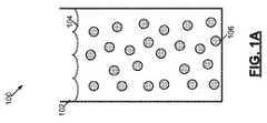
図1A、図1B、図1C、及び図1Dは、ターゲット領域102を洗浄又は殺菌する例示的システムを示している。図1Aは、第1の期間100中の例示的システムを示している。図1Aでは、複数の気泡106を含む流体104が、ターゲット領域102内に入れられる。流体104は、炭酸ガスを含む流体(例えば、ソーダ水、炭酸入り清涼飲料、ビール、シャンパン、又は類似の濃度の気泡を含む別の流体)、窒素化された流体、水素化された流体、又は別の組成の気泡(例えば、薬剤又はヨウ素のような殺菌物質を含む気泡)を含む流体とすることができる。このような流体は、1リットルにつき約1000から100,000,000泡の泡濃度を有する。気泡106は、約0.1μmから500μm範囲の直径を有し、かつミクロ気泡(直径0.1μmから5μm)及びマクロ気泡(直径5μmから500μm)として識別することができる。流体104は、例えば、水溶液又は生理食塩水溶液とすることができる。通常の流体と図1A、図1B、図1C、及び図1Dの例に使用されるような流体104との差は、ミクロ気泡の濃度であり、流体104におけるミクロ気泡の濃度は、通常の流体に対して数桁高い。流体104では、ミクロ気泡は、他のミクロ気泡と結合してマクロ気泡を形成することができる。ターゲット領域102は、洗浄又は殺菌される腔、管、通路、開口部、又は表面である(例えば、根管から除去されるバクテリア又は他の物質を含む根管)。 1A, 1B, 1C, and 1D illustrate an exemplary system for cleaning or sterilizing the
図1Bは、第2の期間120中の例示的システムを示している。第2の期間140中、光ファイバ先端146が、ターゲット領域102に位置決めされる。光ファイバ先端は、電磁放射線放出光ファイバ先端であり、かつ電磁エネルギ源に光ファイバケーブルを通じて接続される。電磁エネルギ源は、光ファイバケーブルに沿って経路指定されて光ファイバ先端146によって放出される電磁放射線144を発生させる。光ファイバ先端146によって放出された電磁放射線144は、流体104により実質的に吸収される波長を有する。光ファイバ先端146は、様々な異なる形状(例えば、円錐、傾斜、面取り、両面取り)、サイズ、設計(例えば、側面発射、前方発射)、及び材料(例えば、ガラス、サファイア、水晶、中空導波管、液体コア、石英シリカ、酸化ゲルマニウム)とすることができる。一例では、光ファイバ先端146は、400μmの直径を有する無水石英ガラス材料で製造される。更に、図1A、図1B、図1C、及び図1Dのシステムは、システムの発光要素として光ファイバ先端146の使用を示すが、他の例では、様々な導波管、発光要素(例えば、発光ナノ粒子及びナノ構造)、又はミラーと、レンズと、他の光学構成要素とを含むデバイスを発光に向けて光ファイバ先端146の代わりに使用することができる。 FIG. 1B shows an exemplary system during the
以下でより詳細に説明するように、光ファイバ先端146によって放出される電磁放射線144は、流体104により吸収され、それによって音響衝撃波及び圧力波が流体104中に生成される。これらの波は、ターゲット領域102を洗浄又は殺菌するのに使用される流体104の移動(すなわち、高速流体運動)を生成する。音響衝撃波は、非線形の機械的効果(例えば、キャビテーション、乱流、及びマイクロジェット)に関して有効な破壊的かつ洗浄作用を引き起こすことができる。流体104のミクロ気泡は、処理の効率を増幅する。第2の期間120中、音響衝撃波は、少量の液体中の急速なエネルギ吸収により生成される。少量の液体中の急速なエネルギ吸収は、巨大な熱弾性応力を生成し、流体104の容積中に広がって、ターゲット領域102と破壊的に相互作用する音響衝撃波の生成を引き起こす。これらの波は、バクテリアを死滅させてターゲット領域102の表面からあらゆる汚染物質を除去することができる。音響衝撃波は、数マイクロ秒の固有時間を有することができる。 As described in more detail below, the
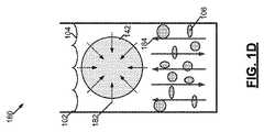
第3の期間140中、蒸気泡142が、流体104中に生成される。蒸気泡142は、流体104により実質的に吸収される波長での電磁放射線144への流体104の露出により生成される。流体104中の電磁放射線144の高い吸収のために、蒸気泡142は、光ファイバ先端146の端部の近くに形成される。蒸気泡142の膨張及び崩壊によって生成された圧力波は、泡106の圧縮及び変形、及びターゲット領域の102の更なる洗浄又は殺菌に寄与する流体104の付加的な移動を引き起こす。圧力波は、蒸気泡142の膨張及び崩壊により誘起される液体変位に関連し、かつ約100マイクロ秒の固有時間を有する。 During the
上述したように、流体104は、電磁放射線144を実質的に吸収するように構成される。図1B及び図1Cでは、流体104は、水性であり、電磁放射線は、水性流体104中で実質的に吸収される約1.8μmから10.6μm又は0.157μmから300μmの範囲の波長を有する。一例では、電磁放射線144は、約1.8μmから10.6μm又は0.157μmから300μmの範囲の波長,0.5μsから10msの範囲のパルス持続時間、20mJのパルスエネルギ、及び200Wの平均パルス電力を有する光のパルスとして流体104に送出される。 As described above, the fluid 104 is configured to substantially absorb the
第4の期間180中、蒸気泡142は、最大直径に到達した後に、内向きの矢印182によって示すように崩壊する。蒸気泡142の崩壊は、急速な内破を含み、内破は、圧力波を流体104中で生成する。圧力波は、高速流体運動184を流体104中に生成する。流体104のガスマクロ気泡106に入射する圧力波は、ガスマクロ気泡106の少なくとも一部を圧縮し、圧縮に続いて、図1Cに示すように、ガスマクロ気泡106は膨張する。特に、気泡106は、爆発性蒸気泡142により生成される圧力波が、蒸気泡142自体の近くだけではなくターゲット領域102の全体を通してより大きな効果を有することができるように流体104の圧縮性を増大させる。ガスマクロ気泡106を欠くシステムでは、流体104は、均一かつ圧縮性が劣る流体であり、爆発性蒸気泡142により生成される圧力波は、蒸気泡142からの距離が増加するにつれてターゲット領域102において効果が少なくなる。すなわち、ガスマクロ気泡106を有する流体104の使用は、ターゲット領域102内のより深くではなく、光ファイバ先端146がターゲット領域102の上部の近くで置かれ、光ファイバ先端146がターゲット領域102において破断するのを防止しやすくすることができ、また流体運動効果の達成を可能にすることができる。 During the
ターゲット領域102内の流体104中の気泡106の使用は、音響衝撃波の生成に必要とされるエネルギの閾値量を低減し、ターゲット領域102との破壊的な相互作用効率を増大させる。圧力波の作用中の気泡106の変形も、ターゲット領域102から汚染物質を流動させて除去する流体104の特性を改善する。 The use of
音響衝撃波及び爆発性蒸気泡によって発生される流体104中の高速流体運動184は、ターゲット領域102の洗浄又は殺菌に関わっているキャビテーション、乱流、マイクロジェット、及び内破を生成する。例示的システムは、圧力波及び気泡106の圧縮及び膨張により生成される高速流体運動184が、バクテリアをターゲット領域102内から除去するか又は死滅させるように使用される。別の例では、高速流体運動184により生成されるキャビテーション及び内破は、細胞の膜を断裂して細胞を歯の象牙質マトリックスから引き抜くことができる。このような細胞及びバクテリアは、気泡106と同様に、音響衝撃波及び圧力波に反応する場合があり、かつ圧縮及び膨張する場合がある。一部の例では、圧力波の力による圧縮及び膨張又は衝撃は、細胞及びバクテリアを死滅させるのに十分であると考えられる。従って、音響衝撃波、圧力波、及び高速流体運動184は、管内バクテリア又はターゲット領域102の表面上に常在するバクテリアを破壊するか又は死滅させる歯内治療学的処置の一部として使用することができる。 High
ターゲット領域102は、小さいサイズ(例えば、光ファイバ先端146のオーダーのサイズ)である場合があり、更には、人体の腔、管、通路、開口部、又は表面(例えば、根管通路、歯の細管、虫歯、血管)とすることができる。従って、電磁エネルギ源を使用してターゲット領域102を洗浄又は殺菌する図1A、図1B、図1C、及び図1Dのシステムは、様々な医療処置又は歯科処置(例えば、組織治療、表面からの堆積物及び汚れの除去、バクテリア除去又は死滅)との関連で使用することができる。例えば、図1A、図1B、図1C、及び図1Dのシステムは、根管治療処置の一部として使用することができ、高速流体運動184は、根管洗浄、根管内のバクテリア除去又は死滅、又は治療を根管に適用するのに使用される。図1A、図1B、図1C、及び図1Dのシステムの歯以外の用途は、導管(例えば、血管)のような人体通路又は硬又は軟組織内の開口部、腔又は内腔内の処置(例えば、塞いだ動脈又は壊死の骨の治療)を含む。図1A、図1B、図1C、及び図1Dのシステムの別の使用は、皮膚(例えば、にきび症状を有する皮膚)の表面の症状の治療にある。 The
図2は、電磁エネルギ源202を利用してターゲット領域210を洗浄又は殺菌する例示的システム200のブロック図を示している。図2のシステム200では、電磁エネルギ源202は、システム200に使用される流体によってよく吸収される特定の波長で電磁放射線を発生させるように構成される。図1B、図1C、及び図1Dを参照すると、特定の波長での電磁放射線は、流体104を露光してターゲット領域102を洗浄又は殺菌する音響衝撃及び圧力波を生じるために使用される。電磁エネルギ源202は、電磁放射線送出システム204及びコントローラ212に接続される。電磁放射線送出システム204は、特定の波長で電磁エネルギを放出するように構成される。電磁放射線送出システム204は、相互作用ゾーン208に接続(例えば、相互作用ゾーン208に位置決め)され、かつ特定の波長での電磁放射線のピーク集中を相互作用ゾーン208内の流体上へ集束させるか又はそこに置く。例示的システムでは、電磁放射線送出システム204は、光ファイバケーブル及び光ファイバ先端を含む。このシステムでは、光ファイバケーブルは、電磁エネルギ源202によって発生された電磁放射線を相互作用ゾーン208への放出に向けて光ファイバ先端に経路指定する。別の例示的システムでは、光ファイバ先端及び光ファイバケーブルは使用されず、相互作用ゾーン208内の流体は、別の手段(例えば、導波管、発光ナノ粒子又はナノ構造、量子ドット、又はミラーと、レンズと、他の光学構成要素とを含むデバイス)を通じて電磁放射線に露出される。相互作用ゾーン208は、ターゲット領域210内に延びるか又はターゲット領域210に隣接する容積である。更に、図1B、図1C、及び図1Dを参照すると、相互作用ゾーン208は、電磁放射線送出システム204から放出された電磁放射線と流体とが音響衝撃及び圧力波を流体中に形成するために相互作用する区域を含む。 FIG. 2 shows a block diagram of an
相互作用ゾーン208は、流体を相互作用ゾーン208に供給するように構成された流体送出システム206にも接続される。流体送出システム206は、流体源203からの流体を受け入れる。一例では、流体送出システム206は、相互作用ゾーン208を含む容積を流体で満たすように構成される。相互作用ゾーン208は、腔、開口部、管、又は通路の一部である場合があり、流体送出システム206は、腔、開口部、管、又は通路の一部を流体で満たすように構成することができる。流体は、二酸化炭素気泡を含む炭酸入り流体(例えば、ソーダ水、炭酸入り清涼飲料、ビール、シャンパン、又は類似の濃度の気泡を含む別の流体)とすることができ、又は複数の窒素気泡又は別の組成の気泡(例えば、薬剤又はヨウ素のような殺菌物質を含む気泡)を含む炭酸なしの流体とすることができる。 The
コントローラ212は、電磁エネルギ源202と、流体源203と、流体送出システム206とに接続され、かつ相互作用ゾーン208への電磁放射線送出及び流体送出を同期させるために使用される。流体は、電磁放射線送出前に相互作用ゾーン208に送出することができ、又は放射線と同時に送出することができる。コントローラ212は、相互作用ゾーン208への電磁放射線送出及び流体送出を同期させるだけではなく、電磁エネルギ源202、流体源203、及び流体送出システム206の様々な作動パラメータを制御する。例示的システムでは、電磁エネルギ源202は、1つ又はそれよりも多くの可変波長光源を含み、コントローラ212により、ユーザは、電磁放射線送出システム204によって放出される光の特定の波長を変えるように1つ又はそれよりも多くの可変波長光源を制御することができる。ユーザは、放出される波長を使用される特定の流体の吸収特性に調節するために、電磁放射線送出システム204によって放出される特定の波長を変えることができる。別の例示的システムでは、電磁エネルギ源202は、複数の光源を含む。この例では、システム200は、より様々な流体と協働するように装備され、ユーザは、コントローラ212を通じて、複数の光源のうちのどれが使用されるかを選択する。
電磁エネルギ源202は、様々な異なるレーザ、レーザダイオード、又は他の光源を含むことができる。電磁エネルギ源202は、約2.70から2.80μmの範囲の波長を有する光を発生させるエルビウム、クロム、イットリウム、スカンジウム、ガリウムガーネット(Er、Cr:YSGG)固体レーザを使用することができる。他の例に使用されるレーザシステムは、2.94μmの波長を有する光を発生させるエルビウム、イットリウム、アルミニウムガーネット(Er:YAG)固体レーザ、2.69μmの波長を有する光を発生させるクロム、ツリウム、エルビウム、イットリウム、アルミニウムガーネット(CTE:YAG)固体レーザ、約2.71から2.86μmの範囲の波長を有する光を発生させるエルビウム、オルトアルミン酸イットリウム(Er:YAL03)固体レーザ、2.10μmの波長を有する光を発生させるホルミウム、イットリウム、アルミニウムガーネット(Ho:YAG)固体レーザ、266nmの波長を有する光を発生させる4倍ネオジム、イットリウム、アルミニウムガーネット(4倍Nd:YAG)固体レーザ、193nmの波長を有する光を発生させるフッ化アルゴン(ArF)エキシマレーザ、308nmの波長を有する光を発生させる塩化キセノン(XeCl)エキシマレーザ、248nmの波長を有する光を発生させるフッ化クリプトン(KrF)エキシマレーザ、及び約9.0から10.6μmの範囲の波長を有する光を発生させる二酸化炭素(CO2)レーザを含む。 The
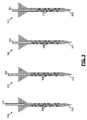
図3は、光ファイバ先端304が管302に対して異なる位置に置かれた例示的な液体洗浄システム300、320、340、360を示している。管302は、上部(例えば、歯内の管髄腔)でのより広い開口部を含み、かつ底の近くでのより短い直径に漸減する。例示的システム300、320、340、360の各々では、気泡を含む流体306が、管302内に入れられる。光ファイバ先端304は、電磁放射線のピーク集中を流体306上へ集束させるか又は置くように構成され、電磁放射線は、流体306により実質的に吸収される波長を有する。流体306は、電磁放射線を吸収して、管302を洗浄するか又は管302内のバクテリアを死滅させるように構成された流体306の高速運動を引き起こす圧力波を生じる。 FIG. 3 illustrates an exemplary
管302に対して異なる位置での光ファイバ先端304の配置は、流体306の高速運動の特性及び管302の洗浄の特性に影響を与える場合がある。システム300では、光ファイバ先端304は、管302の上部でより広い開口部の近くに置かれ、かつこのより広い開口部内に中心が置かれる。システム320では、光ファイバ先端304は、同様に管302内に中心が置かれるが、管302のより広い開口部内でより深い位置に位置決めされる。システム340では、光ファイバ先端304は、特定の距離(例えば、2ミリメートル)で管302の本体の内側に位置決めされ、システム360では、光ファイバ先端304は、より深い距離(例えば、3ミリメートル)で管304の本体の内側に位置決めされる。例示的システム300、320、340、360の各々では、光ファイバ先端304は、管304の深さ全体にわたって挿入されず、これは、光ファイバ先端304又は光ファイバ先端304に接続された光ファイバケーブルが管302内で破断するのを防止しやすくすることができる。システム300、320、340、360の各々では、管302は、光ファイバ先端304のサイズのオーダーの寸法を有する。 The placement of the
図4は、管内402又は管402の入口の近くで光ファイバ先端403を中心に置くために使用される自動調心光ファイバ先端システム400、4440を示している。上述の図で示したターゲット領域を洗浄又は殺菌するシステムは、光ファイバ先端を腔、開口部、通路、又は管内でその中心に置くか、又は光ファイバ先端を腔、開口部、通路、又は管の入口の近くでその中心に置くことが望しいであろう。光ファイバ先端をこれらのシステムにおいて調心することで、腔、開口部、通路、又は管を洗浄又は殺菌する最適な流体運動を生成することができる。図4の自動調心光ファイバ先端システム400、440は、光ファイバ先端403のこの調心を達成するために使用される。 FIG. 4 shows self-aligning fiber optic tip systems 400, 4440 that are used to center the
自動調心光ファイバ先端システム400、440は、光ファイバ先端403の一部分にわたって装着されたクラッド層404、444を利用して、先端403を管402内又は管402の入口の近くでその中心に置くことを可能にする。システム400、440間のクラッド層404、444の様々な厚みにより、光ファイバ先端403は、管402に対して異なる位置でその中心に置かれる。具体的には、システム400のクラッド層404により、先端403を管402内でその中心に置くことができ、システム440のクラッド層444により、先端403を管402の入口の近くでその中心を置くことができる。他の設計を利用して、類似の自動調心光ファイバ先端システムを生成することができる。一例では、自動調心光ファイバ先端システムは、光ファイバ先端403周りに装着されて図4のクラッド層404、444と同様の目的に機能する取外し可能なバンドを含む。 Self-aligning fiber
図5は、ターゲット領域を複数の気泡を含む流体で洗浄又は殺菌する方法の態様を示す例示的タイミング図500、540を示している。タイミング図500は、時間504の単位を表すX軸と、放出された放射線502のピーク電力をワットで表すY軸とを有するグラフである。図1Cを参照すると、タイミング図500は、蒸気泡142を流体104中で生成するために使用される電磁放射線144の送出に関連する態様を示している。1msの時点で、電磁放射線のパルス506が、光ファイバ先端によって放出される。パルス506は、流体(例えば、図1Bの流体104)によってよく吸収されて、蒸気泡が流体中に形成されることを可能にする。図5のタイミング図500では、パルス506は、100μsの幅と、20mJのパルスエネルギと、200Wのピーク電力とを有する。図5は、101msの時点での電磁放射線の第2のパルス508を示し、第1の波長での電磁放射線のパルスが、10Hzの周波数で出力される(すなわち、パルス間の周期は100msとなる)ように構成されることを示している。例示的システムでは、パルス506、508は、ターゲット領域を洗浄又は殺菌する最大量の高速流体運動が流体中に生成されるように液体洗浄システムの共振周波数に適合する周波数で送出される。この例では、共振周波数は、他の変数の中でも、システムに使用される流体、電磁エネルギ源の特性、及びターゲット領域の寸法の関数とすることができる。 FIG. 5 shows exemplary timing diagrams 500, 540 illustrating aspects of a method for cleaning or sterilizing a target region with a fluid containing a plurality of bubbles. Timing diagram 500 is a graph having an X-axis representing units of
タイミング図540は、時間544の単位を表すX軸と、蒸気泡542の直径をミリメートルで表すY軸とを有するグラフである。図1Bを参照すると、タイミング図540は、流体104が電磁放射線144により励起された後に形成された蒸気泡142の泡サイクルの態様を示している。1msの時点で、流体を励起するのに使用されるパルス506に応答して、蒸気泡546が流体中に生成される。図5のタイミング図540では、蒸気泡546は、1mmのピーク最大直径と、約1msの泡サイクルとを有する。グラフ540に示すように、流体は、パルス506により電磁放射線に露出された状態で、蒸気泡546を形成し始める。蒸気泡546は、最大直径に到達するまで直径が増加し、その後に、約1msの泡サイクルの経過に伴って崩壊する(すなわち、急速に爆裂する)。第2の泡548が、第2のパルス508の結果として流体中に形成され、かつ第1の泡546と同様の特性を有する。蒸気泡546、548の膨張及び崩壊は、圧力波を流体中に生成し、圧力波は、ターゲット領域の区域を洗浄又は殺菌するのに使用される流体の移動(すなわち、高速運動)を引き起こす。 Timing diagram 540 is a graph having an X axis that represents units of
図6は、管内殺菌又は洗浄のために歯606の根管604に挿入された光ファイバケーブル602を示している。光ファイバケーブル602は、電磁放射線を電磁エネルギ源608から図6の例では管604内に実質的な距離を延びるケーブル602の光ファイバ先端まで経路指定する。他の例では、光ファイバケーブル602は、管604内に実質的な距離で挿入されるのではなく、光ファイバ先端は、その代わりに管604に入口の近くに位置決めされ、又は管604内により短い距離で挿入される(例えば、図3及び図4に示すように)。 FIG. 6 shows a
光ファイバケーブル602は、歯606の各部を洗浄又は殺菌するか又は歯606からバクテリアを除去するために、前出図に説明したシステム及び方法と共に使用することができる。上述のシステム及び方法を実施するために、管604は、複数の気泡を含む流体(例えば、炭酸入り流体、窒素気泡を含む流体、又は別の組成の気泡を含む流体)で満たされ、ケーブル602の光ファイバ先端は、圧力波及び関連の高速流体運動を生成するために流体を電磁放射線に露出するのに使用される。図6では、高速流体運動を通じて洗浄されるターゲット領域は、管604の長さ内に様々な領域を含む。他の例では、光ファイバケーブル602は、虫歯又は人体の他の腔、開口部、又は通路に挿入することができる。このような腔、開口部、及び通路は、約光ファイバケーブル602のサイズの寸法を有することができる。 The
光ファイバケーブル602及び関連付けられた光ファイバ先端の特性は、ターゲット領域の洗浄又は殺菌をもたらすために変えることができる。例えば、ファイバ602は、様々な設計(例えば、放射放出先端、側面発射先端、前方発射先端、面取り先端、円錐先端、傾斜先端)の単一ファイバ又はマルチファイバ束を含むことができる。更に、光ファイバケーブル602の直径は、変えることができ、ケーブルは、ファイバ直径がケーブルの長さにわたって増加又は低減するテーパ形状の設計を有することができる。光ファイバケーブル602の光ファイバ先端は、洗浄されるターゲット領域から様々な距離に位置決めすることができる。特定の例では、光ファイバケーブル602の光ファイバ先端は、ターゲット領域から数ミリメートルに位置決めされ(例えば、管の底から数ミリメートル離れて位置決めされ、管の底がターゲット領域である)、他の例では、光ファイバ先端は、ターゲット領域と直接に接触して(すなわち、ターゲット領域の近くに)位置決めすることができる。 The properties of the
図7は、洗浄を補助するために研磨材747を利用するターゲット領域702を洗浄する例示的方法を示している。図7のターゲット領域702は、死滅又は除去されるバクテリア又は除去される他のデブリ704を含む容積である。ターゲット領域702は、ヒト又は動物の体の腔、開口部、通路、管、又は表面(例えば、ヒト又は動物の根管又は血管)である場合があり、ターゲット領域702は、殺菌又は洗浄を必要とするあらゆるタイプの腔、開口部、通路、管、又は表面である場合もある。一例では、ターゲット領域702は、デバイス使用後に殺菌又は洗浄を必要とする医療又は歯科デバイスの一部分である。別の例では、ターゲット領域702は、デバイス製造中に洗浄を必要とするマイクロ電子デバイス又は機械式デバイスの一部分である。 FIG. 7 illustrates an exemplary method for cleaning a
第1の期間700中、ターゲット領域702は、バクテリア又はデブリ704を含む。デブリは、様々な堆積物(例えば、歯垢、結石、汚れ、粒子状物質、接着剤、生体物質、洗浄処理からの残留物、埃、汚れ)を含む場合がある。バクテリア又はデブリ704がターゲット領域702の表面上にのみ位置するように示されているが、他の例では、バクテリア又はデブリは、ターゲット領域自体の内側容積内に位置する場合がある(例えば、ターゲット領域702を満たす気体又は液体内に浮遊する)。 During the
バクテリア又はデブリ704をターゲット領域702から除去するために、第2の期間740中、複数の気泡744を含む液体742が、ターゲット領域702に入れられる。気泡744は、二酸化炭素気泡、窒素気泡、又は別の組成の気泡とすることができる。別の組成の気泡は、ターゲット領域702からバクテリア又はデブリ704を除去するように特別に設計された組成の気泡を含むことができる。例えば、ヨウ素気泡は、バクテリアを死滅させるためにターゲット領域702に入れることができる。他の組成の気泡744は、抗生物質、ステロイド、麻酔薬、抗炎症治療薬、消毒剤、殺菌剤、アドレナリン、エピネフリン、アストリンゼン、ビタミン、薬草、及び鉱物のような薬剤を含む気泡を含むことができる。気泡744は、例えば、約0.1μmから500μmの範囲の直径を有することができる。 In order to remove bacteria or
流体742は、気泡744に加えて、研磨材747も含む。研磨材747は、流体742をターゲット領域702に入れる前又は後に流体742と結合される。他の例示的システムでは、研磨材747を使用する代わりに、流体742に組み合わせる他の付加的な材料は、薬剤、生物活性粒子、ナノ粒子、殺菌剤、又は抗生物質を含む。研磨材747は、バクテリア又はデブリ704をターゲット領域702から除去する際に気泡744と協働するように構成される。一例では、研磨材747は、約1μmから50μmの範囲の直径を有する酸化アルミニウム粒子を有する酸化アルミニウム粉体を含む。 The fluid 742 includes an abrasive 747 in addition to the
第3の期間780中、流体742は、流体742により実質的に吸収される波長を有する電磁放射線782に露出される。電磁放射線782は、電磁エネルギ源781によって発生される。図1Cに示すように、電磁エネルギ源781は、ターゲット領域702内の流体742の露光をもたらすために光ファイバケーブル及び光ファイバ先端に結合することができる。代替的に、電磁放射線782は、光ファイバケーブル及び光ファイバ先端を伴わない異なる方法で流体742に送出することができる。電磁放射線782を流体742に送出するこのような代替方法は、電磁放射線782のピーク集中をターゲット領域702内の流体742上へ集束させるか又は置くあらゆるシステムを含むことができる。一例では、光を集束させるように構成された標準的な光学レンズが、流体742を電磁放射線782のピーク集中に露出するのに使用される。電磁放射線782の供給源781は、レーザ、レーザダイオード、ランプ、又は流体742中で実質的に吸収される波長を有する電磁放射線782を生成するように構成されたあらゆる他の光源とすることができる。 During the
流体742による電磁放射線782の吸収は、圧力波を流体742内に生成する。圧力波は、デブリ704を除去し、かつバクテリア704を死滅させるか又はターゲット領域702から除去するように構成された流体及び気泡784の高速運動を引き起こす。流体及び気泡784の高速運動は、強力な集中した力をデブリ及びバクテリア704へ与えることによってデブリ704を分解し、バクテリア704を死滅させるか又は除去する。一例では(例えば、図1C及びIDに示すように)、流体742による電磁放射線782の吸収は、その後に圧力波を流体742中に生成する爆発性蒸気泡を生成する。圧力波は、圧縮及び膨張を少なくとも流体742の気泡744の一部において引き起こす。圧力波による気泡744の圧縮及び膨張は、同じくターゲット領域702を通して高速流体運動784に寄与する乱流及びマイクロジェットを流体742中に生成する。研磨材747は、圧力波によって影響を受け、高速流体運動784は、力をバクテリア及びデブリ704に与えてターゲット領域702からバクテリア及びデブリ704を除去するのに使用される。 Absorption of
図8は、ターゲット領域を洗浄又は殺菌する例示的方法を示す流れ図800である。802で、複数の気泡を含む流体を相互作用ゾーンに入れる。相互作用ゾーンは、ターゲット領域内に延びるか又はターゲット領域に隣接する容積である。804で、相互作用ゾーン内の流体が、流体により実質的に吸収される波長を有する電磁放射線に露出される。806で、相互作用ゾーン内の流体は、電磁放射線を実質的に吸収して音響衝撃波及び圧力波を生じる。音響衝撃波及び圧力波は、ターゲット領域を洗浄又は殺菌するように構成された流体の移動を引き起こす。 FIG. 8 is a flow diagram 800 illustrating an exemplary method for cleaning or sterilizing a target area. At 802, a fluid containing a plurality of bubbles is placed in an interaction zone. The interaction zone is a volume that extends into or is adjacent to the target area. At 804, the fluid in the interaction zone is exposed to electromagnetic radiation having a wavelength that is substantially absorbed by the fluid. At 806, fluid in the interaction zone substantially absorbs electromagnetic radiation and produces acoustic shock waves and pressure waves. Acoustic shock waves and pressure waves cause movement of fluids configured to clean or sterilize the target area.
本発明の開示を詳細にかつ特定の実施形態を参照して説明したが、実施形態の精神及び範囲から逸脱することなく様々な変形及び修正を行うことができることは当業者には明らかであろう。すなわち、本発明の開示は、特許請求の範囲及び均等物の範囲に留まることを条件として本発明の開示の修正及び変形を包含するように意図している。 Although the present disclosure has been described in detail and with reference to specific embodiments, it will be apparent to those skilled in the art that various changes and modifications can be made without departing from the spirit and scope of the embodiments. . That is, the disclosure of the present invention is intended to cover modifications and variations of the disclosure of the present invention provided that they remain within the scope of the claims and equivalents.
本明細書の説明で及び特許請求の範囲を通して用いる時の「a」、「an」、及び「the」の意味は、前後の関連により明確な特に断らない限り、複数の参照を含むことを理解しなければならない。また、本明細書の説明で及び特許請求の範囲を通して用いる時の「in」の意味は、前後の関連により明確な特に断らない限り、「in」及び「on」を含む。更に、本明細書の説明で及び特許請求の範囲を通して用いる時の「各々」の意味は、前後の関連により明確な特に断らない限り、「各々かつ全て」を必要としない。最後に、本明細書の説明で及び特許請求の範囲を通して用いる時の「及び」及び「又は」の意味は、前後の関連により明確な特に断らない限り、接続語及び離接語の両方を含み、かつ交換可能に使用することができ、語句「を除き」は、離接的意味だけが適用される場合がある状況を示すために使用することができる。 It is understood that the meanings of “a”, “an”, and “the” as used in the description herein and throughout the claims include plural references unless the context clearly dictates otherwise. Must. In addition, the meaning of “in” when used in the description of the present specification and throughout the scope of the claims includes “in” and “on” unless clearly specified otherwise by the relations before and after. Further, the meaning of "each" as used in the description and throughout the claims does not require "each and all" unless expressly stated otherwise by context. Finally, the meanings of “and” and “or” as used in the description and throughout the claims include both conjunctive and disjunctive terms, unless the context clearly indicates otherwise. And the phrase “except” can be used to indicate a situation where only disjunctive meaning may apply.
200 例示的システム
204 電磁放射線送出システム
206 流体送出システム
208 相互作用ゾーン
210 ターゲット領域200
Claims (25)
Translated fromJapanese複数の気泡を含む流体を前記ターゲット領域内に延びるか又は該ターゲット領域に隣接する容積である相互作用ゾーンに入れる段階と、
前記相互作用ゾーン内の前記流体を該流体により実質的に吸収される波長を有する電磁放射線に露出する段階と、
を含み、
前記相互作用ゾーン内の前記流体は、前記電磁放射線を実質的に吸収し、前記ターゲット領域を洗浄又は殺菌するように構成された該流体の移動及びキャビテーション効果を引き起こす音響衝撃波及び圧力波を生じる、
ことを特徴とする方法。A method of cleaning or sterilizing a target area,
Entering a fluid containing a plurality of bubbles into an interaction zone that extends into or is adjacent to the target region;
Exposing the fluid in the interaction zone to electromagnetic radiation having a wavelength substantially absorbed by the fluid;
Including
The fluid in the interaction zone generates acoustic shock waves and pressure waves that substantially absorb the electromagnetic radiation and cause movement and cavitation effects of the fluid configured to clean or sterilize the target area;
A method characterized by that.
前記爆発性蒸気泡の膨張及び崩壊は、前記圧力波を発生させる、
ことを特徴とする請求項1に記載の方法。The absorption of electromagnetic radiation creates explosive vapor bubbles in the fluid that expand and collapse,
Expansion and collapse of the explosive vapor bubble generates the pressure wave;
The method according to claim 1.
前記マクロ気泡は、約5μmから500μmの範囲の直径を有する、
ことを特徴とする請求項1に記載の方法。The pressure waves cause compression and expansion of the macro bubbles of the bubbles, and the compression and expansion of the macro bubbles and the pressure waves are the movement of the fluid configured to clean or sterilize the target area. Causing the cavitation effect,
The macrobubbles have a diameter in the range of about 5 μm to 500 μm;
The method according to claim 1.
前記ミクロ気泡は、約0.1μmから5μmの範囲の直径を有する、
ことを特徴とする請求項1に記載の方法。The acoustic shock wave is amplified by the microbubbles of the plurality of bubbles,
The microbubbles have a diameter in the range of about 0.1 μm to 5 μm;
The method according to claim 1.
を更に含むことを特徴とする請求項1に記載の方法。Positioning an electromagnetic radiation emitting optical fiber tip in the interaction zone configured to emit the electromagnetic radiation to perform exposure of the fluid in the interaction zone to the electromagnetic radiation;
The method of claim 1 further comprising:
前記波長は、約1.8μmから10.6μm又は0.157μmから300μmの範囲内である、
ことを特徴とする請求項1に記載の方法。The fluid is aqueous;
The wavelength is in the range of about 1.8 μm to 10.6 μm or 0.157 μm to 300 μm.
The method according to claim 1.
前記複数の前記パルスは、前記流体と前記ターゲット領域とを含むシステムの共振周波数に適合する周波数で送出される、
ことを特徴とする請求項14に記載の方法。Exposing the fluid to the pulse of the electromagnetic radiation comprises exposing the fluid to a plurality of the pulses of the electromagnetic radiation;
The plurality of pulses are delivered at a frequency that matches a resonant frequency of a system that includes the fluid and the target region.
15. The method of claim 14, wherein:
を更に含むことを特徴とする請求項1に記載の方法。Abrasives, nanoparticles, agents configured to wash the target area, remove or kill bacteria in the target area, sterilize the target area, or apply medical treatment to the target area, Combining bioactive particles, bactericides, or antibiotics with the fluid;
The method of claim 1 further comprising:
複数の気泡を含み、前記ターゲット領域内に延びるか又は該ターゲット領域に隣接する容積である相互作用ゾーンに入れられる流体と、
前記流体により実質的に吸収される波長を有する電磁放射線を生成するように構成された電磁エネルギ源であって、該電磁放射線が、前記相互作用ゾーンで該流体を露光し、該相互作用ゾーン内の該流体が、該電磁放射線を実質的に吸収して、前記ターゲット領域を洗浄又は殺菌するように構成された該流体の移動及びキャビテーション効果を引き起こす音響衝撃波及び圧力波を生じる前記電磁エネルギ源と、
を含むことを特徴とするシステム。A system for cleaning or sterilizing a target area,
A fluid comprising a plurality of bubbles and extending into an interaction zone that is a volume extending into or adjacent to the target region;
A source of electromagnetic energy configured to generate electromagnetic radiation having a wavelength substantially absorbed by the fluid, the electromagnetic radiation exposing the fluid in the interaction zone and within the interaction zone The electromagnetic energy source that generates acoustic shock waves and pressure waves that substantially absorb the electromagnetic radiation and cause movement and cavitation effects of the fluid configured to clean or sterilize the target area; ,
A system characterized by including.
Applications Claiming Priority (5)
| Application Number | Priority Date | Filing Date | Title |
|---|---|---|---|
| US201161541743P | 2011-09-30 | 2011-09-30 | |
| US61/541,743 | 2011-09-30 | ||
| PCT/US2012/058332WO2013049832A2 (en) | 2011-09-30 | 2012-10-01 | Pressure wave root canal cleaning system |
| US13/632,628 | 2012-10-01 | ||
| US13/632,628US20130084545A1 (en) | 2011-09-30 | 2012-10-01 | Pressure Wave Root Canal Cleaning System |
Publications (1)
| Publication Number | Publication Date |
|---|---|
| JP2014528286Atrue JP2014528286A (en) | 2014-10-27 |
Family
ID=47992898
Family Applications (1)
| Application Number | Title | Priority Date | Filing Date |
|---|---|---|---|
| JP2014533478APendingJP2014528286A (en) | 2011-09-30 | 2012-10-01 | Pressure wave root canal cleaning system |
Country Status (5)
| Country | Link |
|---|---|
| US (2) | US20130084545A1 (en) |
| EP (1) | EP2760368A4 (en) |
| JP (1) | JP2014528286A (en) |
| CA (1) | CA2850483C (en) |
| WO (1) | WO2013049832A2 (en) |
Families Citing this family (25)
| Publication number | Priority date | Publication date | Assignee | Title |
|---|---|---|---|---|
| US10835355B2 (en) | 2006-04-20 | 2020-11-17 | Sonendo, Inc. | Apparatus and methods for treating root canals of teeth |
| SI3311770T1 (en) | 2006-04-20 | 2023-11-30 | Sonendo, Inc. | Apparatus for treating root canals of teeth |
| US7980854B2 (en)* | 2006-08-24 | 2011-07-19 | Medical Dental Advanced Technologies Group, L.L.C. | Dental and medical treatments and procedures |
| US12114924B2 (en) | 2006-08-24 | 2024-10-15 | Pipstek, Llc | Treatment system and method |
| CN102724929B (en)* | 2009-11-13 | 2016-04-13 | 索南多股份有限公司 | For liquid jet equipment and the method for dental treatment |
| CN103347462B (en) | 2010-10-21 | 2017-05-10 | 索南多股份有限公司 | Devices, methods and combinations for endodontics |
| US20130173903A1 (en)* | 2011-12-29 | 2013-07-04 | Eric T. Obligacion | Unified network architecture having storage devices with secure boot devices |
| CN110623765A (en) | 2012-03-22 | 2019-12-31 | 索南多股份有限公司 | Apparatus and method for cleaning teeth |
| US10631962B2 (en) | 2012-04-13 | 2020-04-28 | Sonendo, Inc. | Apparatus and methods for cleaning teeth and gingival pockets |
| US10363120B2 (en) | 2012-12-20 | 2019-07-30 | Sonendo, Inc. | Apparatus and methods for cleaning teeth and root canals |
| EP3943042B1 (en) | 2012-12-20 | 2024-03-13 | Sonendo, Inc. | Apparatus for cleaning teeth and root canals |
| CA3132712A1 (en) | 2013-02-04 | 2014-08-07 | Sonendo, Inc. | Dental treatment system |
| EP2991576B1 (en) | 2013-05-01 | 2022-12-28 | Sonendo, Inc. | Apparatus and system for treating teeth |
| US9877801B2 (en) | 2013-06-26 | 2018-01-30 | Sonendo, Inc. | Apparatus and methods for filling teeth and root canals |
| US9987200B2 (en)* | 2014-09-04 | 2018-06-05 | Syact, Llp | Activated micro-bubble based root canal disinfection |
| EP3510961B1 (en) | 2015-08-03 | 2021-06-09 | Fotona d.o.o. | Cleaning system |
| EP3222245B1 (en) | 2016-03-22 | 2021-09-22 | Dentsply Sirona Inc. | Method and arrangement for cleaning of a canal |
| US10806544B2 (en) | 2016-04-04 | 2020-10-20 | Sonendo, Inc. | Systems and methods for removing foreign objects from root canals |
| US11648085B2 (en)* | 2016-10-24 | 2023-05-16 | George Bruder | Endodontic system and instrument for irrigation and disinfection of a tooth root canal |
| BR112020005143B1 (en) | 2017-09-25 | 2022-08-30 | Degudent Gmbh | METHOD AND PROVISION FOR CLEANING A CHANNEL |
| US11638634B2 (en) | 2017-09-25 | 2023-05-02 | Dentsply Sirona Inc. | Method and arrangement for cleaning of a canal |
| JP2021520247A (en) | 2018-04-03 | 2021-08-19 | コンバージェント デンタル, インコーポレイテッド | Laser system for surgical applications |
| USD997355S1 (en) | 2020-10-07 | 2023-08-29 | Sonendo, Inc. | Dental treatment instrument |
| US20230233299A1 (en)* | 2022-01-27 | 2023-07-27 | EdgeEndo, LLC | Dental, endodontic, and periodontic treatment methods and systems |
| DE102023102821A1 (en)* | 2023-02-06 | 2024-08-08 | Otto-von-Guericke-Universität Magdeburg, Körperschaft des öffentlichen Rechts | Cleaning device and method for cleaning a surface |
Citations (6)
| Publication number | Priority date | Publication date | Assignee | Title |
|---|---|---|---|---|
| JPS6464648A (en)* | 1987-07-16 | 1989-03-10 | Medeitetsuku Sa | Apparatus for treatment of dental root |
| JP2004215862A (en)* | 2003-01-15 | 2004-08-05 | Tohoku Techno Arch Co Ltd | Shock wave producing device |
| JP3638191B2 (en)* | 1997-01-31 | 2005-04-13 | 信司 國分 | Medical laser handpiece |
| JP2008507327A (en)* | 2004-07-22 | 2008-03-13 | オンディーヌ インターナショナル リミテッド | Acoustophotodynamic therapy for dental applications |
| WO2008157715A2 (en)* | 2007-06-19 | 2008-12-24 | Biolase Technology, Inc. | Fluid controllable laser endodontic cleaning and disinfecting system |
| WO2010099538A1 (en)* | 2009-02-28 | 2010-09-02 | Medical Dental Advanced Technologies Group Llc | Dental and medical treatments and procedures |
Family Cites Families (28)
| Publication number | Priority date | Publication date | Assignee | Title |
|---|---|---|---|---|
| BE821274A (en)* | 1974-10-18 | 1975-02-17 | PROCESS FOR CLEANING, DRYING AND FILLING HAIR TUBES OR OTHER CONDUITS CLOSED TO ONE OF THEIR ENDS AND END DIAMETER | |
| US4148334A (en)* | 1975-09-05 | 1979-04-10 | Fluid Device Corporation | Liquid level control sytem |
| JPH0728874B2 (en)* | 1987-11-17 | 1995-04-05 | 住友電気工業株式会社 | Root canal sterilizer |
| US4940411A (en)* | 1988-08-25 | 1990-07-10 | American Dental Laser, Inc. | Dental laser method |
| US5055043A (en)* | 1990-07-19 | 1991-10-08 | Ervin Weiss | Dental fluid control apparatus |
| US5116227A (en)* | 1991-03-01 | 1992-05-26 | Endo Technic Corporation | Process for cleaning and enlarging passages |
| US5173049A (en)* | 1991-03-01 | 1992-12-22 | Endo Technic Corporation | Removing a post embedded in a tooth |
| US20060240381A1 (en)* | 1995-08-31 | 2006-10-26 | Biolase Technology, Inc. | Fluid conditioning system |
| US5741247A (en)* | 1995-08-31 | 1998-04-21 | Biolase Technology, Inc. | Atomized fluid particles for electromagnetically induced cutting |
| US5846080A (en)* | 1995-12-20 | 1998-12-08 | W&H Dentalwerk Gmbh | Laser dental devices and methods |
| US20020045890A1 (en)* | 1996-04-24 | 2002-04-18 | The Regents Of The University O F California | Opto-acoustic thrombolysis |
| US6165440A (en)* | 1997-07-09 | 2000-12-26 | Board Of Regents, The University Of Texas System | Radiation and nanoparticles for enhancement of drug delivery in solid tumors |
| US6224378B1 (en)* | 1997-07-09 | 2001-05-01 | Surgijet, Inc. | Method and apparatus for dental treatment using high pressure liquid jet |
| US6491685B2 (en)* | 1999-03-04 | 2002-12-10 | The Regents Of The University Of California | Laser and acoustic lens for lithotripsy |
| US20030084916A1 (en)* | 2001-10-18 | 2003-05-08 | Sonia Gaaloul | Ultrasonic cleaning products comprising cleaning composition having dissolved gas |
| US6881061B2 (en)* | 2002-09-30 | 2005-04-19 | Mcneil-Ppc, Inc. | Ultrasonic method for cleaning teeth |
| WO2006110773A2 (en)* | 2005-04-12 | 2006-10-19 | Ekos Corporation | Ultrasound catheter with cavitation promoting surface |
| US8388345B2 (en)* | 2005-04-13 | 2013-03-05 | Clifford J. Ruddle | Method for cleaning a root canal system |
| US20080311540A1 (en)* | 2005-11-28 | 2008-12-18 | Koninklijke Philips Electronics, N.V. | Method and Device For Removing Biofilms By Microsteaming |
| US20100330539A1 (en)* | 2006-08-24 | 2010-12-30 | Medical Dental Advance Technologies Group | Periodontal treatment system and method |
| US7959441B2 (en)* | 2006-08-24 | 2011-06-14 | Medical Dental Advanced Technologies Group, L.L.C. | Laser based enhanced generation of photoacoustic pressure waves in dental and medical treatments and procedures |
| US7980854B2 (en)* | 2006-08-24 | 2011-07-19 | Medical Dental Advanced Technologies Group, L.L.C. | Dental and medical treatments and procedures |
| US20120135368A1 (en)* | 2007-01-26 | 2012-05-31 | Rizoiu Ioana M | Modified-ouput fiber optic tips |
| CA2704732C (en)* | 2007-09-19 | 2012-04-24 | Biolase Technology, Inc. | Probes and biofluids for treating and removing deposits from tissue surfaces |
| EP2194911A2 (en)* | 2007-10-08 | 2010-06-16 | Koninklijke Philips Electronics N.V. | Apparatus for cleaning teeth using a variable frequency ultrasound |
| WO2010052717A1 (en)* | 2008-11-05 | 2010-05-14 | Medicn.R.G. Ltd. | Device and method for dental cavity treatment |
| CN102264434B (en)* | 2008-12-02 | 2016-02-03 | 拜欧利泰克投资二代公司 | The medical procedure of induced with laser steam/plasma-mediated and device |
| CN110623765A (en)* | 2012-03-22 | 2019-12-31 | 索南多股份有限公司 | Apparatus and method for cleaning teeth |
- 2012
- 2012-10-01JPJP2014533478Apatent/JP2014528286A/enactivePending
- 2012-10-01EPEP12835989.0Apatent/EP2760368A4/ennot_activeWithdrawn
- 2012-10-01WOPCT/US2012/058332patent/WO2013049832A2/enactiveApplication Filing
- 2012-10-01USUS13/632,628patent/US20130084545A1/ennot_activeAbandoned
- 2012-10-01CACA2850483Apatent/CA2850483C/enactiveActive
- 2015
- 2015-02-09USUS14/617,593patent/US20150150650A1/ennot_activeAbandoned
Patent Citations (7)
| Publication number | Priority date | Publication date | Assignee | Title |
|---|---|---|---|---|
| JPS6464648A (en)* | 1987-07-16 | 1989-03-10 | Medeitetsuku Sa | Apparatus for treatment of dental root |
| JP3638191B2 (en)* | 1997-01-31 | 2005-04-13 | 信司 國分 | Medical laser handpiece |
| JP2004215862A (en)* | 2003-01-15 | 2004-08-05 | Tohoku Techno Arch Co Ltd | Shock wave producing device |
| JP2008507327A (en)* | 2004-07-22 | 2008-03-13 | オンディーヌ インターナショナル リミテッド | Acoustophotodynamic therapy for dental applications |
| WO2008157715A2 (en)* | 2007-06-19 | 2008-12-24 | Biolase Technology, Inc. | Fluid controllable laser endodontic cleaning and disinfecting system |
| WO2010099538A1 (en)* | 2009-02-28 | 2010-09-02 | Medical Dental Advanced Technologies Group Llc | Dental and medical treatments and procedures |
| JP2012519039A (en)* | 2009-02-28 | 2012-08-23 | メディカル・デンタル・アドヴァンスド・テクノロジーズ・グループ・エルエルシー | Dental and medical remedies and treatments |
Also Published As
| Publication number | Publication date |
|---|---|
| EP2760368A4 (en) | 2015-08-26 |
| WO2013049832A3 (en) | 2013-06-13 |
| CA2850483A1 (en) | 2013-04-04 |
| CA2850483C (en) | 2018-07-10 |
| EP2760368A2 (en) | 2014-08-06 |
| US20130084545A1 (en) | 2013-04-04 |
| WO2013049832A2 (en) | 2013-04-04 |
| US20150150650A1 (en) | 2015-06-04 |
Similar Documents
| Publication | Publication Date | Title |
|---|---|---|
| JP2014528286A (en) | Pressure wave root canal cleaning system | |
| US11350993B2 (en) | Dental and medical treatments and procedures | |
| US20220313405A1 (en) | Apparatus and methods for cleaning teeth | |
| US20210085435A1 (en) | Apparatus and methods for cleaning teeth and gingival pockets | |
| US12114924B2 (en) | Treatment system and method | |
| US9572632B2 (en) | Laser system and method for operating the laser system | |
| US20190021827A1 (en) | Method and apparatus for laser induced thermo-acoustical streaming of liquid | |
| US20130236857A1 (en) | Cavitation Medication Delivery System | |
| US20140220511A1 (en) | Periodontal treatment system and method | |
| US20140087333A1 (en) | Periodontal treatment system and method | |
| US20040259053A1 (en) | Method and apparatus for laser-assisted dental scaling | |
| JP2017514601A (en) | Apparatus and method for cleaning teeth and root canal | |
| CN102438542A (en) | Dental and medical treatments and procedures | |
| EP3003209A2 (en) | System and method for treatment of endodontic/periodontic conditions | |
| US20230356000A1 (en) | System and method for laser based endodontic treatment |
Legal Events
| Date | Code | Title | Description |
|---|---|---|---|
| A131 | Notification of reasons for refusal | Free format text:JAPANESE INTERMEDIATE CODE: A131 Effective date:20150420 | |
| A601 | Written request for extension of time | Free format text:JAPANESE INTERMEDIATE CODE: A601 Effective date:20150721 | |
| A521 | Request for written amendment filed | Free format text:JAPANESE INTERMEDIATE CODE: A523 Effective date:20151020 | |
| A131 | Notification of reasons for refusal | Free format text:JAPANESE INTERMEDIATE CODE: A131 Effective date:20151109 | |
| A02 | Decision of refusal | Free format text:JAPANESE INTERMEDIATE CODE: A02 Effective date:20160404 |