JP2014528068A - Temperature sensor, temperature measurement device, and medical system including temperature sensor or temperature measurement device - Google Patents
Temperature sensor, temperature measurement device, and medical system including temperature sensor or temperature measurement deviceDownload PDFInfo
- Publication number
- JP2014528068A JP2014528068AJP2014530276AJP2014530276AJP2014528068AJP 2014528068 AJP2014528068 AJP 2014528068AJP 2014530276 AJP2014530276 AJP 2014530276AJP 2014530276 AJP2014530276 AJP 2014530276AJP 2014528068 AJP2014528068 AJP 2014528068A
- Authority
- JP
- Japan
- Prior art keywords
- temperature
- temperature sensor
- light
- medical engineering
- engineering system
- Prior art date
- Legal status (The legal status is an assumption and is not a legal conclusion. Google has not performed a legal analysis and makes no representation as to the accuracy of the status listed.)
- Granted
Links
Images


Classifications
- A—HUMAN NECESSITIES
- A61—MEDICAL OR VETERINARY SCIENCE; HYGIENE
- A61B—DIAGNOSIS; SURGERY; IDENTIFICATION
- A61B5/00—Measuring for diagnostic purposes; Identification of persons
- A61B5/01—Measuring temperature of body parts ; Diagnostic temperature sensing, e.g. for malignant or inflamed tissue
- A—HUMAN NECESSITIES
- A61—MEDICAL OR VETERINARY SCIENCE; HYGIENE
- A61B—DIAGNOSIS; SURGERY; IDENTIFICATION
- A61B18/00—Surgical instruments, devices or methods for transferring non-mechanical forms of energy to or from the body
- A61B18/04—Surgical instruments, devices or methods for transferring non-mechanical forms of energy to or from the body by heating
- A61B18/12—Surgical instruments, devices or methods for transferring non-mechanical forms of energy to or from the body by heating by passing a current through the tissue to be heated, e.g. high-frequency current
- A61B18/14—Probes or electrodes therefor
- A61B18/1442—Probes having pivoting end effectors, e.g. forceps
- A—HUMAN NECESSITIES
- A61—MEDICAL OR VETERINARY SCIENCE; HYGIENE
- A61B—DIAGNOSIS; SURGERY; IDENTIFICATION
- A61B18/00—Surgical instruments, devices or methods for transferring non-mechanical forms of energy to or from the body
- A61B18/18—Surgical instruments, devices or methods for transferring non-mechanical forms of energy to or from the body by applying electromagnetic radiation, e.g. microwaves
- A61B18/20—Surgical instruments, devices or methods for transferring non-mechanical forms of energy to or from the body by applying electromagnetic radiation, e.g. microwaves using laser
- A—HUMAN NECESSITIES
- A61—MEDICAL OR VETERINARY SCIENCE; HYGIENE
- A61B—DIAGNOSIS; SURGERY; IDENTIFICATION
- A61B5/00—Measuring for diagnostic purposes; Identification of persons
- A61B5/68—Arrangements of detecting, measuring or recording means, e.g. sensors, in relation to patient
- A61B5/6846—Arrangements of detecting, measuring or recording means, e.g. sensors, in relation to patient specially adapted to be brought in contact with an internal body part, i.e. invasive
- A61B5/6847—Arrangements of detecting, measuring or recording means, e.g. sensors, in relation to patient specially adapted to be brought in contact with an internal body part, i.e. invasive mounted on an invasive device
- A—HUMAN NECESSITIES
- A61—MEDICAL OR VETERINARY SCIENCE; HYGIENE
- A61B—DIAGNOSIS; SURGERY; IDENTIFICATION
- A61B5/00—Measuring for diagnostic purposes; Identification of persons
- A61B5/68—Arrangements of detecting, measuring or recording means, e.g. sensors, in relation to patient
- A61B5/6887—Arrangements of detecting, measuring or recording means, e.g. sensors, in relation to patient mounted on external non-worn devices, e.g. non-medical devices
- A—HUMAN NECESSITIES
- A61—MEDICAL OR VETERINARY SCIENCE; HYGIENE
- A61B—DIAGNOSIS; SURGERY; IDENTIFICATION
- A61B5/00—Measuring for diagnostic purposes; Identification of persons
- A61B5/74—Details of notification to user or communication with user or patient; User input means
- A61B5/742—Details of notification to user or communication with user or patient; User input means using visual displays
- G—PHYSICS
- G01—MEASURING; TESTING
- G01K—MEASURING TEMPERATURE; MEASURING QUANTITY OF HEAT; THERMALLY-SENSITIVE ELEMENTS NOT OTHERWISE PROVIDED FOR
- G01K11/00—Measuring temperature based upon physical or chemical changes not covered by groups G01K3/00, G01K5/00, G01K7/00 or G01K9/00
- G01K11/32—Measuring temperature based upon physical or chemical changes not covered by groups G01K3/00, G01K5/00, G01K7/00 or G01K9/00 using changes in transmittance, scattering or luminescence in optical fibres
- G01K11/3206—Measuring temperature based upon physical or chemical changes not covered by groups G01K3/00, G01K5/00, G01K7/00 or G01K9/00 using changes in transmittance, scattering or luminescence in optical fibres at discrete locations in the fibre, e.g. using Bragg scattering
- G01K11/3213—Measuring temperature based upon physical or chemical changes not covered by groups G01K3/00, G01K5/00, G01K7/00 or G01K9/00 using changes in transmittance, scattering or luminescence in optical fibres at discrete locations in the fibre, e.g. using Bragg scattering using changes in luminescence, e.g. at the distal end of the fibres
- G—PHYSICS
- G01—MEASURING; TESTING
- G01K—MEASURING TEMPERATURE; MEASURING QUANTITY OF HEAT; THERMALLY-SENSITIVE ELEMENTS NOT OTHERWISE PROVIDED FOR
- G01K13/00—Thermometers specially adapted for specific purposes
- G01K13/20—Clinical contact thermometers for use with humans or animals
- A—HUMAN NECESSITIES
- A61—MEDICAL OR VETERINARY SCIENCE; HYGIENE
- A61B—DIAGNOSIS; SURGERY; IDENTIFICATION
- A61B17/00—Surgical instruments, devices or methods
- A61B2017/00017—Electrical control of surgical instruments
- A61B2017/00022—Sensing or detecting at the treatment site
- A61B2017/00084—Temperature
- A61B2017/00101—Temperature using an array of thermosensors
- A—HUMAN NECESSITIES
- A61—MEDICAL OR VETERINARY SCIENCE; HYGIENE
- A61B—DIAGNOSIS; SURGERY; IDENTIFICATION
- A61B18/00—Surgical instruments, devices or methods for transferring non-mechanical forms of energy to or from the body
- A61B2018/00571—Surgical instruments, devices or methods for transferring non-mechanical forms of energy to or from the body for achieving a particular surgical effect
- A61B2018/00589—Coagulation
- A—HUMAN NECESSITIES
- A61—MEDICAL OR VETERINARY SCIENCE; HYGIENE
- A61B—DIAGNOSIS; SURGERY; IDENTIFICATION
- A61B18/00—Surgical instruments, devices or methods for transferring non-mechanical forms of energy to or from the body
- A61B2018/00571—Surgical instruments, devices or methods for transferring non-mechanical forms of energy to or from the body for achieving a particular surgical effect
- A61B2018/00601—Cutting
- A—HUMAN NECESSITIES
- A61—MEDICAL OR VETERINARY SCIENCE; HYGIENE
- A61B—DIAGNOSIS; SURGERY; IDENTIFICATION
- A61B18/00—Surgical instruments, devices or methods for transferring non-mechanical forms of energy to or from the body
- A61B2018/00571—Surgical instruments, devices or methods for transferring non-mechanical forms of energy to or from the body for achieving a particular surgical effect
- A61B2018/00619—Welding
- A—HUMAN NECESSITIES
- A61—MEDICAL OR VETERINARY SCIENCE; HYGIENE
- A61B—DIAGNOSIS; SURGERY; IDENTIFICATION
- A61B18/00—Surgical instruments, devices or methods for transferring non-mechanical forms of energy to or from the body
- A61B2018/00636—Sensing and controlling the application of energy
- A61B2018/0066—Sensing and controlling the application of energy without feedback, i.e. open loop control
- A—HUMAN NECESSITIES
- A61—MEDICAL OR VETERINARY SCIENCE; HYGIENE
- A61B—DIAGNOSIS; SURGERY; IDENTIFICATION
- A61B18/00—Surgical instruments, devices or methods for transferring non-mechanical forms of energy to or from the body
- A61B2018/00636—Sensing and controlling the application of energy
- A61B2018/00696—Controlled or regulated parameters
- A61B2018/00714—Temperature
- A—HUMAN NECESSITIES
- A61—MEDICAL OR VETERINARY SCIENCE; HYGIENE
- A61B—DIAGNOSIS; SURGERY; IDENTIFICATION
- A61B18/00—Surgical instruments, devices or methods for transferring non-mechanical forms of energy to or from the body
- A61B2018/00636—Sensing and controlling the application of energy
- A61B2018/00773—Sensed parameters
- A61B2018/00791—Temperature
- A61B2018/00797—Temperature measured by multiple temperature sensors
- A—HUMAN NECESSITIES
- A61—MEDICAL OR VETERINARY SCIENCE; HYGIENE
- A61B—DIAGNOSIS; SURGERY; IDENTIFICATION
- A61B18/00—Surgical instruments, devices or methods for transferring non-mechanical forms of energy to or from the body
- A61B2018/00636—Sensing and controlling the application of energy
- A61B2018/00773—Sensed parameters
- A61B2018/00791—Temperature
- A61B2018/00809—Temperature measured thermochromatically
- A—HUMAN NECESSITIES
- A61—MEDICAL OR VETERINARY SCIENCE; HYGIENE
- A61B—DIAGNOSIS; SURGERY; IDENTIFICATION
- A61B2562/00—Details of sensors; Constructional details of sensor housings or probes; Accessories for sensors
- A61B2562/02—Details of sensors specially adapted for in-vivo measurements
- A61B2562/0271—Thermal or temperature sensors
- A61B2562/0276—Thermal or temperature sensors comprising a thermosensitive compound
Landscapes
- Health & Medical Sciences (AREA)
- Life Sciences & Earth Sciences (AREA)
- Surgery (AREA)
- Physics & Mathematics (AREA)
- Engineering & Computer Science (AREA)
- Animal Behavior & Ethology (AREA)
- Public Health (AREA)
- Veterinary Medicine (AREA)
- Biomedical Technology (AREA)
- Heart & Thoracic Surgery (AREA)
- Medical Informatics (AREA)
- Molecular Biology (AREA)
- General Health & Medical Sciences (AREA)
- Biophysics (AREA)
- Pathology (AREA)
- Otolaryngology (AREA)
- Nuclear Medicine, Radiotherapy & Molecular Imaging (AREA)
- General Physics & Mathematics (AREA)
- Electromagnetism (AREA)
- Plasma & Fusion (AREA)
- Optics & Photonics (AREA)
- Investigating, Analyzing Materials By Fluorescence Or Luminescence (AREA)
- Laser Surgery Devices (AREA)
- Surgical Instruments (AREA)
- Measuring Temperature Or Quantity Of Heat (AREA)
Abstract
Translated fromJapaneseDescription
Translated fromJapanese本発明は、医用工学システム用の温度センサ、前記温度センサを含む温度測定装置、および前記温度センサまたは前記温度測定装置を備える医用工学システムに関する。 The present invention relates to a temperature sensor for a medical engineering system, a temperature measuring device including the temperature sensor, and a medical engineering system including the temperature sensor or the temperature measuring device.
医学的な処置および治療における温度の測定は、特に外科手術において、多くの点で、特に処置や治療の進展を決定して、それを制御する、場合によってはそれを終了するために、重要である。 Measurement of temperature in medical procedures and treatments is important in many respects, especially in surgery, especially to determine and control progress and possibly terminate treatment and treatment progress. is there.
従来の温度センサを用いて、進行中の治療または処置と並行して、何ら影響を受けずに温度の測定を行うことは、多くの場合不可能である。なぜなら、温度の測定に影響をおよぼし、それによって実際に決定される温度値を誤らせてしまう数多くの環境因子が存在するからである。 It is often impossible to make temperature measurements with conventional temperature sensors without any effect in parallel with ongoing therapy or treatment. This is because there are a number of environmental factors that affect the measurement of temperature and thereby distort the actually determined temperature value.
例を挙げると、外科用高周波装置における電気的な擾乱と、レーザ光線により加熱されたときのセンサの直接的な温度上昇のいずれもが、擾乱因子として重要な役割を果たしている。 By way of example, both electrical disturbances in surgical high frequency devices and direct sensor temperature rise when heated by a laser beam play an important role as disturbance factors.
電気外科的なインターベンションにおいて、プロセスの制御は、現在、処置される組織構造の含水量に対応する、組織構造の電気インピーダンスを測定することによって、実現されている。しかしながら、高周波電流の供給時には、温度の測定を行うことができない。 In electrosurgical interventions, control of the process is currently achieved by measuring the electrical impedance of the tissue structure that corresponds to the water content of the tissue structure being treated. However, temperature cannot be measured when high-frequency current is supplied.
また、レーザを適用する場合には、熱電対やサーミスタによる直接的な温度の測定は、これらの素子に固有のレーザエネルギーの吸収があるため、不可能である。 When a laser is applied, direct temperature measurement by a thermocouple or a thermistor is impossible due to absorption of laser energy inherent in these elements.
上記したインピーダンスの測定は、間接的な量として、温度的刺激に対する組織構造の反応を反映することができる。しかしながら、インピーダンスの実質的な変化は、かなりの量の組織水を蒸発させた場合にのみ生じる。実際には、組織構造それ自体は、大幅に低い温度ですでに影響を受け、変化している。例として、コラーゲンにおけるコンフォメーションの変化には、約70℃の温度ですでに達している。温度のほかに、温度的刺激への曝露時間も重要な役割を果たす。このようなプロセスおよび他の化学反応は、アレニウス係数によって記述される。 The impedance measurement described above can reflect the response of the tissue structure to a thermal stimulus as an indirect quantity. However, a substantial change in impedance occurs only when a significant amount of tissue water is evaporated. In practice, the tissue structure itself is already affected and changed at significantly lower temperatures. As an example, the conformational change in collagen has already been reached at a temperature of about 70 ° C. In addition to temperature, exposure time to thermal stimuli also plays an important role. Such processes and other chemical reactions are described by Arrhenius coefficients.
また、インピーダンスの測定は、測定プロセスに関連する組織構造の領域のサイズとともに、電極の距離および接触圧力に大きく依存する。 Also, impedance measurements are highly dependent on electrode distance and contact pressure, as well as the size of the area of tissue structure associated with the measurement process.
さらに、WO2009/005850A1には、処置される組織の状態を評価するために、光透過の測定を用いることが開示されている。この測定プロセスは、汚れに関して誤動作を起こしやすく、多くの場合には観測される組織が到達した状態に関して、十分に意味のあるものとはならない。 Furthermore, WO2009 / 005850A1 discloses the use of light transmission measurements to assess the condition of the treated tissue. This measurement process is prone to malfunctions with respect to dirt and in many cases does not make sense sufficiently with respect to the state where the observed tissue has reached.
本発明の目的は、特に電気外科用の高周波装置を用いた処置の際に、直接的な温度の測定を可能とする、温度センサまたは温度測定装置を提案することである。 The object of the present invention is to propose a temperature sensor or a temperature measuring device which makes it possible to measure the temperature directly, especially during a procedure using a high frequency device for electrosurgery.
この目的は、それぞれ請求項1および請求項7に係る、温度センサおよびそのようなセンサを備える温度測定装置により達成される。 This object is achieved by a temperature sensor and a temperature measuring device comprising such a sensor according to claims 1 and 7, respectively.
本発明は、量子収率、好ましくは発光の量子収率、特に蛍光発光の量子収率が、温度に依存しており、したがって励起されて発光を示すセンサ素子の温度についての尺度となるという効果を利用する。 The present invention has the effect that the quantum yield, preferably the quantum yield of light emission, in particular the quantum yield of fluorescent light emission, is temperature dependent and is therefore a measure for the temperature of the sensor element that is excited and exhibits light emission. Is used.
蛍光媒質の蛍光の量子収率の温度依存性に基づくサンプルの温度の決定それ自体は、WO03/012468A1から公知である。この文献は、その温度が変調された電気エネルギーにより影響を受ける電子部品の表面に蛍光媒体を適用することを提案している。このようにして、励起光に曝露されたサンプルの表面により放射され、変調された蛍光は、画像取込装置によって受光されて、電気エネルギーの変調周波数の位相と結合された状態で評価される。 The determination of the temperature of the sample based on the temperature dependence of the fluorescence quantum yield of the fluorescent medium is known per se from WO 03/012468 A1. This document proposes applying a fluorescent medium to the surface of an electronic component whose temperature is affected by the modulated electrical energy. In this way, the modulated fluorescence emitted and modulated by the sample surface exposed to the excitation light is received by the image capture device and evaluated in combination with the phase of the modulation frequency of the electrical energy.
この従来の方法とは異なり、本発明は、発光媒質および導光体の形態の光取込素子に関して、他の環境的な影響を受けないように発光の量子収率の観測が達成されているという意味で、閉じたシステムで動作し、従って多くの医用工学システムにおいて初めて正常に使用可能なものとなっている。 Unlike this conventional method, the present invention achieves the observation of the quantum yield of light emission so as not to be affected by other environmental influences with respect to the light capturing element in the form of a light emitting medium and a light guide. In that sense, it operates in a closed system and is therefore usable for the first time in many medical engineering systems.
観測されるサンプルの温度を正確に決定するために、本発明は、高価な測定装置を必要とすることなく、特に光学的な観測にアクセスすることが通常できないサンプル表面の温度の測定を可能にする。 In order to accurately determine the temperature of the observed sample, the present invention allows the measurement of the temperature of the sample surface, which usually does not have access to optical observations, without the need for expensive measurement equipment. To do.
本発明の温度センサは、温度センサの環境の光学的な状況とは独立して、発光媒質に光を伝送し、媒質の発光を放出する導光体に光学的に結合しており、動作環境におけるセンサ素子のいかなる汚れも測定結果に影響を及ぼさない。 The temperature sensor of the present invention is optically coupled to a light guide that transmits light to a light emitting medium and emits light emitted from the medium, independently of the optical state of the environment of the temperature sensor, Any contamination of the sensor element in the sensor does not affect the measurement result.
発光の量子収率の決定において、本発明により用いられる温度測定プロセスは、例えば電気外科用の高周波装置の使用時に発生する電気的な擾乱からも影響を受けない。治療的処置の過程におけるレーザ光の併用さえも、擾乱を引き起こすことがない。なぜなら、一方では、レーザ処置についての光の周波数は、および他方では、センサ素子の励起波長および発光波長は、それぞれの場合において、発光の量子収率の測定に影響が無いように選択可能だからである。 In determining the quantum yield of luminescence, the temperature measurement process used by the present invention is not affected by electrical disturbances that occur, for example, when using electrosurgical radio frequency devices. Even the combined use of laser light in the course of therapeutic treatment does not cause disturbance. Because, on the one hand, the frequency of the light for the laser treatment and on the other hand the excitation wavelength and emission wavelength of the sensor element can be chosen in each case so as not to affect the measurement of the quantum yield of the emission. is there.
さらに、励起時に発光を示す媒質を備えるセンサ素子のサイズを非常に小さく保って、それによってセンサ素子の熱容量それ自体を無視できるようにすることができる。また、周囲の組織構造の現在の温度変化を発光の測定を介してモニタリングすることができる。 Furthermore, the size of the sensor element comprising a medium that emits light upon excitation can be kept very small so that the heat capacity of the sensor element itself can be ignored. Also, current temperature changes in the surrounding tissue structure can be monitored via luminescence measurements.
本発明により可能となる直接的な温度の測定を用いて、高周波電流またはレーザ光の適用時においてすでに、組織の状態の特性を明らかにすることができ、組織構造の所望のシーリングプロセスを確認することができる。組織の状態の算出は、上記のアレニウス係数を介して達成することができる。 Using the direct temperature measurements made possible by the present invention, it is possible to characterize the state of the tissue already during the application of high-frequency currents or laser light and confirm the desired sealing process of the tissue structure. be able to. The calculation of the tissue state can be achieved via the Arrhenius coefficient described above.
本発明に係る温度センサおよび温度測定装置は、高周波アプリケーションだけでなく、レーザアプリケーションや、組織構造を加熱する他の形態のエネルギーについても、用いることができる。本発明に係る温度センサ(またはそのようなセンサを備える温度測定装置)を用いた温度の測定は、処置される組織構造および電極間隔のサイズにも依存しない。 The temperature sensor and temperature measuring device according to the present invention can be used not only for high-frequency applications, but also for laser applications and other forms of energy for heating tissue structures. The temperature measurement using the temperature sensor according to the present invention (or a temperature measuring device comprising such a sensor) is also independent of the tissue structure to be treated and the size of the electrode spacing.
本発明の好ましい温度センサは、一方では、励起波長を用いて光を伝送し、他方では、発光波長を有する光を受け入れ、放出する、導光体を備えている。さらに、センサ素子が直接的に導光体に接続されていることが好ましい。 A preferred temperature sensor of the present invention comprises a light guide that, on the one hand, transmits light using an excitation wavelength and, on the other hand, accepts and emits light having an emission wavelength. Furthermore, it is preferable that the sensor element is directly connected to the light guide.
本発明に係る温度センサ用のセンサ素子は、スリーブ内で励起時に発光を示す媒質を備えていてもよい。スリーブは、媒質を取り囲んでおり、特に剛性を有するように設計されていてもよい。スリーブは、光学的に透過性に、または不透明に、例えば内側に向けて反射するように、設計されていてもよい。 The sensor element for a temperature sensor according to the present invention may include a medium that emits light when excited in the sleeve. The sleeve surrounds the medium and may be specifically designed to be rigid. The sleeve may be designed to reflect optically transmissive or opaque, for example inward.
励起時に発光を示す媒質は、流動性の媒質、例えばゲルであってもよい。 The medium that emits light upon excitation may be a fluid medium, such as a gel.
励起時に発光を示す好ましい媒質は、好ましくは、固体の形態の媒質、特に固体レーザに使用される結晶である。これらは、ルビー、サファイヤ、添加型イットリウム・アルミニウム・ガーネット(YAG)結晶、例えばER:YAG、ND:YAG、YB:YAG、およびアレキサンドライトを含んでいる。 A preferred medium that emits light upon excitation is preferably a solid form medium, in particular a crystal used in a solid state laser. These include ruby, sapphire, doped yttrium aluminum garnet (YAG) crystals such as ER: YAG, ND: YAG, YB: YAG, and alexandrite.
特にこれらの材料の利点は、その高い熱伝導性、耐熱性および機械的強度である。 In particular, the advantages of these materials are their high thermal conductivity, heat resistance and mechanical strength.
他方では、プラスチック材料、例えば蛍光色素で機能化したPEEKを、励起時に発光を示す媒質として使用してもよい。機能化したプラスチック材料の利点は、それらの多様な利用可能性、単純なプロセス性、および材料の低コストにある。特に、PEEKは医療技術における広範な使用および良好な耐熱性の点で優れている。 On the other hand, a plastic material, for example PEEK functionalized with a fluorescent dye, may be used as a medium that emits light upon excitation. The advantages of functionalized plastic materials lie in their diverse availability, simple processability, and low cost of materials. In particular, PEEK is excellent in terms of wide use in medical technology and good heat resistance.
さらに、蛍光色素で機能化した他の耐熱性のプラスチック材料、例えばエポキシ樹脂も、適している。 Furthermore, other heat-resistant plastic materials functionalized with fluorescent dyes, for example epoxy resins, are also suitable.
蛍光色素で機能化したプラスチック材料の場合、プラスチック材料は、それぞれの用途に適した多数の利用可能な材料から選択することができる。 In the case of plastic materials functionalized with fluorescent dyes, the plastic material can be selected from a number of available materials suitable for the respective application.
本発明の温度センサが蛍光媒質を取り囲む剛性を有するスリーブを有する、あるいは上記のように固体として設計されている場合、温度センサそれ自体が、高周波アプリケーションにおいて、電極に電流が供給されたときの短絡を防ぐために電極を規定の間隔で維持する、スペーサとしての役割を果たすことができる。 When the temperature sensor of the present invention has a rigid sleeve surrounding the fluorescent medium or is designed as a solid as described above, the temperature sensor itself is shorted when current is supplied to the electrodes in high frequency applications. In order to prevent this, it can serve as a spacer that keeps the electrodes at regular intervals.
温度センサとして、およびスペーサとして両用できることで、温度の測定を、エネルギーの入力箇所に可能な限り近づけて、すなわち組織構造の処置される領域と直接的に接触させて、行うことができる。スペーサおよびセンサ素子は、すぐ近傍における温度変化を観測することを可能にする。 Since it can be used both as a temperature sensor and as a spacer, the temperature can be measured as close as possible to the energy input point, that is, in direct contact with the treated region of the tissue structure. Spacers and sensor elements make it possible to observe temperature changes in the immediate vicinity.
すでに詳述した温度センサのほかに、医用工学システム用の本発明の温度装置は、励起波長を放射する光源、特にレーザと、発光検出器、例えばフォトセルをさらに備えている。 In addition to the temperature sensor already described in detail, the temperature device according to the invention for a medical engineering system further comprises a light source emitting an excitation wavelength, in particular a laser, and a light emission detector, for example a photocell.
好ましい温度測定装置は、互いの間が所定の距離となるように、2次元または3次元のマトリックス状に、マウント内に受け入れられ配置された、いくつかの温度センサを備えている。本発明に係る温度センサのセンサ素子は小さな寸法を実現可能であるため、それらを外科器具および医用工学システムの従来の構成要素に組み込むことができ、場合によってはそれらの構成要素がマウントの役割を果たす。 A preferred temperature measurement device comprises a number of temperature sensors received and arranged in a mount in a two-dimensional or three-dimensional matrix so that there is a predetermined distance between each other. Since the sensor elements of the temperature sensor according to the present invention can achieve small dimensions, they can be incorporated into conventional components of surgical instruments and medical engineering systems, and in some cases these components can serve as mounts. Fulfill.
最後に、本発明は、1またはそれ以上の本発明に係る温度センサまたは上記の温度測定装置を備える医用工学システムに関する。 Finally, the present invention relates to a medical engineering system comprising one or more temperature sensors according to the present invention or a temperature measuring device as described above.
好ましい医用工学システムは、外科用システム、特に超音波、レーザまたは電気外科用のシステムとして実装される。 Preferred medical engineering systems are implemented as surgical systems, particularly ultrasonic, laser or electrosurgical systems.
本発明の好ましい医用工学システムは、その外科用システムが、患者の組織構造を切断、切開、凝固、シーリング、および/または接続する装置を備えている点で、優れている。 The preferred medical engineering system of the present invention is advantageous in that the surgical system includes a device for cutting, incising, coagulating, sealing, and / or connecting patient tissue structures.
本発明に係る温度センサを用いることによって、従来のインピーダンスの測定の場合に比べて、組織構造の変化を、はるかに正確に、かつ早い時点で、検出することが可能となる。なぜなら、処置される組織構造の含水量は、温度の測定において直接的な影響が無いからである。 By using the temperature sensor according to the present invention, it is possible to detect a change in tissue structure much more accurately and at an earlier time point than in the case of conventional impedance measurement. This is because the water content of the tissue structure to be treated has no direct influence on the temperature measurement.
本発明に係る温度センサを、機械的応力および高温に対して高い耐性を有するセンサ素子材料の適切な選択をすることで、処置される組織構造に直接的に適用することができるので、直接的な温度の測定が実現される。これは、従来技術において代替技術として推奨されている、処置される組織構造から放射される赤外線の測定よりも、はるかに優れている。この形態については、例えばUS2007/0179484A1を参照のこと。 The temperature sensor according to the present invention can be applied directly to the tissue structure to be treated by making an appropriate selection of sensor element materials having high resistance to mechanical stress and high temperature, Temperature measurement is realized. This is far superior to the measurement of infrared radiation emitted from the tissue structure to be treated, which is recommended as an alternative technique in the prior art. See US 2007/0179484 A1 for this form.
多くの場合、組織構造の処置のための本発明に係る医用工学システムは、特にアプリケータジョーと呼ばれる形態の、2つのアプリケータ要素を有するアプリケータツールを備えている。アプリケータジョーは、互いに対して動作可能であって、開放された休止姿勢から閉鎖された作用姿勢へと移行可能である。ここで、本発明に係る温度センサの1つは、好ましくは、少なくとも1つのアプリケータ要素内に、または少なくとも1つのアプリケータジョー内に配置されるであろう。 In many cases, the medical engineering system according to the invention for the treatment of tissue structures comprises an applicator tool having two applicator elements, particularly in the form of an applicator jaw. The applicator jaws are operable with respect to each other and can transition from an open resting position to a closed working position. Here, one of the temperature sensors according to the invention will preferably be arranged in at least one applicator element or in at least one applicator jaw.
アプリケータ要素は、特にそれらが外科用の高周波装置の一部である場合、アプリケータ要素を作用姿勢において互いに対して所定の距離で保つスペーサを備えており、スペーサは、特に本発明の温度センサを備えている。特に、温度センサまたはそのセンサ素子それ自体を、スペーサとして実装することも可能である。 The applicator elements comprise spacers that keep the applicator elements at a predetermined distance relative to each other in the working position, especially when they are part of a surgical high-frequency device, the spacers being particularly temperature sensors according to the invention. It has. In particular, the temperature sensor or its sensor element itself can be mounted as a spacer.
本発明の好ましい医用工学システムは、アプリケータ要素が所定のアプリケーション姿勢、特に作用姿勢になるまで、温度センサのアクティブ化をブロックする、防御機構を備えている。この措置により、医用工学システムの温度センサが偶発的に周囲へ光を放射してしまうことを防ぐことができる。この事は、レーザが発光の励起のための光源として使用される場合に、特に重要である。 The preferred medical engineering system of the present invention comprises a defensive mechanism that blocks activation of the temperature sensor until the applicator element is in a predetermined application position, in particular a working position. This measure can prevent the temperature sensor of the medical engineering system from accidentally emitting light to the surroundings. This is particularly important when the laser is used as a light source for excitation of light emission.
上記の防御機構は、好ましくは、スイッチング要素、特にアプリケータ要素の姿勢をモニタリングする、光学的、電気的または機械的な接触子を備えている。 The protective mechanism preferably comprises an optical, electrical or mechanical contact that monitors the attitude of the switching element, in particular the applicator element.
防御機構は、少なくとも1つのアプリケータ要素の温度を測定する、別個の温度センサをさらに備えていてもよい。この温度センサによって、アプリケータ要素が、通常は体温である組織構造とすでに接触しているか否かを確認することが可能となる。 The defense mechanism may further comprise a separate temperature sensor that measures the temperature of the at least one applicator element. This temperature sensor makes it possible to check whether the applicator element is already in contact with the tissue structure, which is usually body temperature.
すでに述べたように、本発明に係る医用工学システムは、好ましくは高周波ジェネレータ、本発明に係る温度測定装置またはセンサ、温度プロファイルを評価する装置、および/または温度センサによって測定された温度値に基づいてシステムに関連する機能を調節または制御する装置を備えている。 As already mentioned, the medical engineering system according to the invention is preferably based on a high-frequency generator, a temperature measuring device or sensor according to the invention, a device for evaluating a temperature profile, and / or a temperature value measured by a temperature sensor. And a device for adjusting or controlling functions related to the system.
本発明のさらに好ましい医用工学システムでは、アプリケータ要素は、特に確実な組織構造の把持を容易にする構造化された表面領域を備えている。この手段により、特に、治療的処置の際の、処置されるべき組織のアプリケータ要素に対する、意図しないずれ動きを回避することができる。 In a further preferred medical engineering system according to the invention, the applicator element comprises a structured surface area that facilitates a particularly secure grasping of the tissue structure. By this means it is possible to avoid unintentional misalignment movements with respect to the applicator element of the tissue to be treated, in particular during a therapeutic treatment.
グリッド状に構造化された表面は、構造化された表面として、特に適している。 A surface structured in a grid is particularly suitable as a structured surface.
さらに好ましい医用工学システムは、プライマ材料についての計量装置も備えている。場合によっては、このプライマ材料は、特にコラーゲンまたはゼラチン系の材料の形態で利用可能とすることができる。 Further preferred medical engineering systems also comprise a metering device for the primer material. In some cases, this primer material may be made available in the form of a collagen or gelatin-based material in particular.
本発明のこれらのおよび他の利点は、図面を用いて以下でより詳細に説明する。 These and other advantages of the invention are described in more detail below with reference to the drawings.
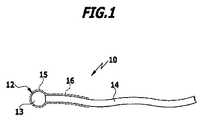
図1は、本発明の温度センサを示す。温度センサは、全体として参照符号10が付されており、球形状のルビー結晶の形態のセンサ素子12と、センサ素子12に取り付けられた導光体14を備えている。導光体14は、センサ素子12に光学的に接続されている。本発明に係る温度センサ10のこの実施形態では、単一の導光体14のみが設けられており、その導光体14が、センサ素子12の励起媒質13の発光のための励起波長を備える光の供給と、媒質13から放射される励起波長によって誘導された発光の受け入れおよび放出の、両方の役割を果たす。センサ素子12は、媒質13を取り囲み、センサ素子を導光体14に接続する、スリーブ15(図1では破線で示す)を備えていてもよい。場合によっては、導光体14は、クラッド材16(図1では破線で示す)によって取り囲まれていてもよく、クラッド材16は、その一部について、好ましくは物質間接合によって、センサ素子のスリーブ15に接続されている。 FIG. 1 shows a temperature sensor of the present invention. The temperature sensor is generally denoted by
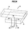
図2Aは、温度測定装置20を示している。温度測定装置20においては、3つの温度センサ22a、22b、22cが、それらのセンサ素子24a、24b、24cが三角形のマトリックス状に配置されるように、マウント21内に支持されている。 FIG. 2A shows the
模式的に示されたサンプル本体26は、空間分解能を有する態様で、温度を決定することが可能となる。 The
図2Bは、温度測定装置30を示す。温度測定装置30も、3つの温度センサ32a、32b、32cを備えている。温度センサ32a、32b、32cは、それらのセンサ素子34a、34bおよび34cが、直線的に等間隔で配置されるように、互いに離れて配置されている。 FIG. 2B shows the
同時に、センサ素子34a、34b、34cは、マウント36の表面から突出しており、これによって、ボディ38までの距離が規定される。ボディ38は、マウント36と組み合わせて、例えば高周波電流に対する一組のアプリケータ要素を構成していてもよい。 At the same time, the
図3は、本発明に係る温度センサのセンサ素子の発光媒体の機能原理を模式的に示している。 FIG. 3 schematically shows the functional principle of the light emitting medium of the sensor element of the temperature sensor according to the present invention.
励起波長λ1を有する光の吸収によって、励起に応じて発光を示す媒質は、活性化状態E1から活性化励起状態E3へと変化する。その状態から、媒質は熱的に緩和によって励起状態E2へと戻る。波長λ2を有する光の放射の下で、システムは、励起状態E2から活性化状態E1へと戻る。この事について、励起時に発光を示す媒質を代表するルビー結晶に基づいて、以下でより詳細に説明する。 By absorbing light having the excitation wavelength λ1, the medium that emits light in response to excitation changes from the activated state E1 to the activated excited state E3. From that state, the medium returns to the excited state E2 by thermal relaxation. Under the emission of light having wavelength λ2, the system returns from the excited state E2 to the activated state E1. This will be described in more detail below based on a ruby crystal representing a medium that emits light upon excitation.
ルビー結晶において、クロムイオンは、ここでは蛍光の形態で放射される発光の原因となっている。クロムイオンは、最適なスペクトル吸収帯域を有しており、それを介して大きな量子収率で蛍光発光が励起される。赤色のスペクトル領域内の発光波長が約694nmであるのに対して、緑色のスペクトル領域内の吸収帯域の1つは、約532nmの励起波長で、(励起時に発光を示す媒質である)ルビー結晶の励起を可能にする。観測される量子収率は温度に依存する。すなわち、放射される光子の吸収される光子に対する個数の比率は、温度の上昇とともに減少する。この温度依存性は、処置された身体組織の十分に正確な温度値を提供するために、医学において着目される、約30℃から約150℃の間の温度範囲において、非常に顕著である。 In the ruby crystal, chromium ions are responsible for the light emission emitted here in the form of fluorescence. Chromium ions have an optimum spectral absorption band, through which fluorescence emission is excited with a large quantum yield. While the emission wavelength in the red spectral region is about 694 nm, one of the absorption bands in the green spectral region is an excitation wavelength of about 532 nm, which is a ruby crystal (which is a medium that emits light upon excitation). Allows for excitation. The observed quantum yield depends on the temperature. That is, the ratio of the number of emitted photons to absorbed photons decreases with increasing temperature. This temperature dependence is very pronounced in the temperature range between about 30 ° C. and about 150 ° C., which is noted in medicine to provide a sufficiently accurate temperature value of the treated body tissue.
励起光と蛍光発光の2つの波長は、それらの光の割合が問題なく光学的に分離でき、波長λ2を有する蛍光の量子収率が容易かつ正確に決定できる程度に、互いに離れている。 The two wavelengths of the excitation light and the fluorescence emission are separated from each other to such an extent that the proportion of the light can be optically separated without any problem and the quantum yield of the fluorescence having the wavelength λ2 can be easily and accurately determined.
図4は、50℃から115℃までの範囲の温度に対する、ルビー結晶の蛍光の量子収率を示している。得られている曲線は、身体組織のシーリングに用いられる、ルビー結晶を備える本発明に係る温度センサの校正に役立てることができる。 FIG. 4 shows the quantum yield of ruby crystal fluorescence for temperatures ranging from 50 ° C. to 115 ° C. The obtained curve can be used to calibrate a temperature sensor according to the present invention with a ruby crystal used for sealing body tissue.
温度と、蛍光の量子収率(ここでは、強度またはフォトダイオードのカウントとしてプロットしている)の間に、ほぼ線形の依存性があることが分かる。測定値は、温度制御されたファーネス内に配置されたルビー結晶を用いて、一定の励起光強度で取得されている。 It can be seen that there is a nearly linear dependence between temperature and the quantum yield of fluorescence (here plotted as intensity or photodiode count). The measured value is acquired at a constant excitation light intensity using a ruby crystal placed in a temperature-controlled furnace.
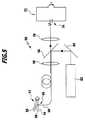
図5は、本発明に係る医用工学システム50の概略図を示している。 FIG. 5 shows a schematic diagram of a
医用工学システム50は、患者の組織構造をシーリングおよび/または接続する装置(参照符号52が付されている)を備えている。図5の概略図において、この装置は、互いに回動可能に連結されている2つのアプリケータジョー54,55に省略して描かれている。アプリケータジョー54,55に電流を供給するために必要なジェネレータと、アプリケータジョー54,55を組織構造に適用する装置は、当業者には知られており、簡略化のため図5では省略している。 The
本発明に係る温度センサ56は、1つのアプリケータジョー54内に配置されている。そのセンサ素子58は、アプリケータジョー54内に、2つのアプリケータジョー54および55が直接的に導電的な接触に至ることを防止し、これによってジョー54と55の間の短絡を回避するスペーサの役割も果たすことができるように、設計および配置がされている。 The
センサ素子58のほかに、温度センサ56は、それに取り付けられた導光体60を備えている。 In addition to the
医用工学システム50はさらに、レーザ62の形態の光源を備えている。レーザ62のレーザ光線は、ミラー64およびダイクロイックミラー66を介して、導光体60に結合される。レーザ62は、Nd:YAGレーザであり、その出力光は周波数が2倍にされており、従って約532nmの波長を有している。 The
結合に使用される光学系は、図5において模式的にレンズ68によって示されている。導光体60を介して、レーザ62の励起光がセンサ素子58およびその内部に配置された励起時に発光を示す媒質(本実施例でもルビー結晶)に照射され、図3および図4に関連して上述したように、約694nmの波長を有する蛍光を生じる。その蛍光は、ルビー結晶によって等方的に放射される。導光体60は、実際にはこの放射された光の一部のみを検出するが、その一部を一定の割合で検出しており、従って導光体60により受け入れたセンサ素子58のルビー結晶の蛍光による光は、全体の量子収率を示している。蛍光による光は、導光体60によって光学系68を介して伝送され、約532nmの励起波長を反射し、694nmの波長の通過を許容するように設計された、ダイクロイックミラー66を通過する。ダイクロイックミラー66を通過した後、赤色の蛍光による光は更なる光学系70を介して検出器72およびそのフォトダイオード74に案内されて、そこで強度として評価される電圧信号Uが生成される。 The optical system used for coupling is schematically illustrated by
センサ素子58および導光体60を組み合わせた温度センサ56と、光源としてのレーザ62と、検出器72は、本発明の温度測定装置を構成する。本発明に係る温度測定装置の好ましい実施形態においては、図5に医用工学システム50の一部として示すように、導光体60が、励起波長を有する光をセンサ素子58へ伝送する役割と、励起媒質の蛍光を検出器72へ伝送する役割の、両方を果たす。光学系68および70と、ミラー64および66は、温度測定装置の内部における、最適な光の経路のために設けられている。 The
センサ素子58および励起時に発光を示す媒質として使用されるルビー結晶が、アプリケータジョー54の表面から突出するように配置されており、それがアプリケータジョー54,55の間にある組織と直接的に接触するという事実により、その組織のどのような温度変化もセンサ素子58に直接的に伝わる。ルビー結晶の蛍光の量子収率の温度依存性(図4参照)に起因して、アプリケータジョー54,55の間に保持された組織の温度は、検出器72の異なる電圧信号から決定することができる。 A ruby crystal, which is used as a
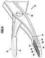
図6は、例として、2つのアプリケータジョー54,55をより詳細に示している。それらは、ヒンジ部80によって、互いに電気的に絶縁されるように、回動可能に支持されている。 FIG. 6 shows two
2つの温度センサ56,56’は、それらのセンサ素子58,58’とともに、アプリケータジョー54内に配置されている。センサ素子58,58’は、励起時に発光を示すそれらの媒質を備えている。それらの媒質は、アプリケータジョー54の表面から突出しており、それによってストッパ、すなわちアプリケータジョー55の閉鎖姿勢に対するスペーサを形成している。2つのアプリケータジョー54,55は、導電性の電極82,83を備えている。電極82,83は電流を供給可能であり、好ましくは、図6に示すように、構造化された表面、特にグリッド状に構造化されており、アプリケータジョー54,55の間に保持される処置されるべき組織物質が処置中に滑ることを防ぐような表面を備えている。 The two
Claims (21)
Translated fromJapanese励起時に発光、特に蛍光発光を示す媒質を含むセンサ素子と、
前記センサ素子に光学的に接続されており、前記媒質に励起波長を有する光を供給し、および/または、励起時に発光を示す前記媒質の発光波長を有する光を受け入れ、放出するように構成された導光体を備える温度センサ。A temperature sensor for a medical engineering system,
A sensor element including a medium that emits light when excited, in particular fluorescent light emission;
Optically connected to the sensor element and configured to supply light having an excitation wavelength to the medium and / or to receive and emit light having an emission wavelength of the medium that emits light upon excitation. Temperature sensor comprising a light guide.
前記スリーブが、前記媒質を取り囲んでおり、特に剛性を有するように設計されている、請求項1から4の何れか一項の温度センサ。The sensor element includes the medium that emits light when excited in a sleeve;
5. The temperature sensor according to claim 1, wherein the sleeve surrounds the medium and is designed to be particularly rigid. 6.
1またはそれ以上の請求項1から7の何れか一項の温度センサと、
前記励起波長を放射する光源、特にレーザと、
好ましくはフォトセルの形態の、発光検出器を備えている、温度測定装置。A temperature measuring device for a medical engineering system,
One or more temperature sensors according to any one of claims 1 to 7;
A light source that emits said excitation wavelength, in particular a laser;
A temperature measuring device comprising a luminescence detector, preferably in the form of a photocell.
前記アプリケータジョーは、互いに対して動作可能であって、開放された休止姿勢から閉鎖された作用姿勢へと移行可能であって、
温度センサが、好ましくは、少なくとも1つの前記アプリケータ要素内に配置されている、請求項12の医用工学システム。Said device comprises an applicator tool having two applicator elements, in particular in the form of an applicator jaw;
The applicator jaws are operable relative to each other and can be transitioned from an open rest position to a closed working position;
The medical engineering system of claim 12, wherein a temperature sensor is preferably disposed within the at least one applicator element.
前記スペーサが、特に温度センサを備えている、請求項13の医用工学システム。The applicator elements comprise spacers that keep the applicator elements at a predetermined distance relative to each other in the working position;
14. The medical engineering system of claim 13, wherein the spacer comprises in particular a temperature sensor.
Applications Claiming Priority (3)
| Application Number | Priority Date | Filing Date | Title |
|---|---|---|---|
| DE102011053755ADE102011053755A1 (en) | 2011-09-19 | 2011-09-19 | Temperature sensor, temperature measuring device and medical systems with a temperature sensor or a temperature measuring device |
| DE102011053755.4 | 2011-09-19 | ||
| PCT/EP2012/068401WO2013041550A2 (en) | 2011-09-19 | 2012-09-19 | Temperature sensor, temperature measuring apparatus and medical systems with a temperature sensor or a temperature measuring apparatus |
Publications (2)
| Publication Number | Publication Date |
|---|---|
| JP2014528068Atrue JP2014528068A (en) | 2014-10-23 |
| JP6031521B2 JP6031521B2 (en) | 2016-11-24 |
Family
ID=47044965
Family Applications (1)
| Application Number | Title | Priority Date | Filing Date |
|---|---|---|---|
| JP2014530276AActiveJP6031521B2 (en) | 2011-09-19 | 2012-09-19 | Temperature sensor, temperature measurement device, and medical system including temperature sensor or temperature measurement device |
Country Status (6)
| Country | Link |
|---|---|
| US (1) | US10244946B2 (en) |
| EP (1) | EP2758759B1 (en) |
| JP (1) | JP6031521B2 (en) |
| CN (1) | CN103907001B (en) |
| DE (1) | DE102011053755A1 (en) |
| WO (1) | WO2013041550A2 (en) |
Cited By (1)
| Publication number | Priority date | Publication date | Assignee | Title |
|---|---|---|---|---|
| JP2021525858A (en)* | 2018-05-22 | 2021-09-27 | ワットロー・エレクトリック・マニュファクチャリング・カンパニー | Fiber optic probe with dual sealing and compression elements |
Families Citing this family (7)
| Publication number | Priority date | Publication date | Assignee | Title |
|---|---|---|---|---|
| JP6335673B2 (en)* | 2014-06-17 | 2018-05-30 | 京セラ株式会社 | Measuring apparatus and measuring method |
| CN106572878B (en) | 2014-07-22 | 2020-04-10 | 皇家飞利浦有限公司 | Tissue sealing device with optical feedback |
| CN104771202B (en)* | 2015-04-30 | 2017-06-23 | 青岛理工大学 | Grinding temperature on-line detection and nano fluid phase-change heat type grinding device |
| US10314645B2 (en)* | 2016-03-16 | 2019-06-11 | Ethicon Llc | Surgical end effectors with increased stiffness |
| CN110274708B (en)* | 2019-07-12 | 2020-04-10 | 西安交通大学 | Tumor cell nanoscale quantum three-dimensional thermal imaging system |
| DE102019121366A1 (en) | 2019-08-07 | 2021-02-11 | Aesculap Ag | Apparatus and method for measuring tissue temperature |
| CN111855010A (en)* | 2020-08-17 | 2020-10-30 | 北京遥测技术研究所 | High-temperature narrow environment non-contact temperature measuring device based on special optical fiber |
Citations (7)
| Publication number | Priority date | Publication date | Assignee | Title |
|---|---|---|---|---|
| JP2002340698A (en)* | 2001-05-11 | 2002-11-27 | Ohkura Electric Co Ltd | Integrating sphere type optical fiber thermometer |
| US20020183734A1 (en)* | 2001-02-26 | 2002-12-05 | Bommannan D. Bommi | System and method for reducing post-surgical complications |
| JP2003093402A (en)* | 2002-07-25 | 2003-04-02 | Olympus Optical Co Ltd | Operation apparatus |
| JP2007229454A (en)* | 2006-02-16 | 2007-09-13 | Ethicon Endo Surgery Inc | Energy-based treatment system and method |
| US20080009860A1 (en)* | 2006-07-07 | 2008-01-10 | Sherwood Services Ag | System and method for controlling electrode gap during tissue sealing |
| US20080039836A1 (en)* | 2006-08-08 | 2008-02-14 | Sherwood Services Ag | System and method for controlling RF output during tissue sealing |
| US20080125767A1 (en)* | 2003-10-23 | 2008-05-29 | Sherwood Services Ag | Thermocouple Measurement Circuit |
Family Cites Families (20)
| Publication number | Priority date | Publication date | Assignee | Title |
|---|---|---|---|---|
| US4215275A (en)* | 1977-12-07 | 1980-07-29 | Luxtron Corporation | Optical temperature measurement technique utilizing phosphors |
| US4626110A (en) | 1985-05-03 | 1986-12-02 | Luxtron Corporation | Technique for optically measuring the temperature of an ultrasonically heated object |
| US4925327A (en)* | 1985-11-18 | 1990-05-15 | Minnesota Mining And Manufacturing Company | Liquid applicator with metering insert |
| DE3902001C2 (en)* | 1989-01-24 | 1995-08-31 | Tacan Corp | Use of a fluorescent material |
| US5772597A (en)* | 1992-09-14 | 1998-06-30 | Sextant Medical Corporation | Surgical tool end effector |
| US5304809A (en) | 1992-09-15 | 1994-04-19 | Luxtron Corporation | Luminescent decay time measurements by use of a CCD camera |
| US5891142A (en)* | 1996-12-06 | 1999-04-06 | Eggers & Associates, Inc. | Electrosurgical forceps |
| US6579304B1 (en)* | 1997-02-03 | 2003-06-17 | Applied Medical Resources Corporation | Surgical clamp with improved traction |
| US6974450B2 (en)* | 1999-12-30 | 2005-12-13 | Pearl Technology Holdings, Llc | Face-lifting device |
| US7771422B2 (en)* | 2002-06-06 | 2010-08-10 | Nuortho Surgical, Inc. | Methods and devices for electrosurgery |
| EP1379162B1 (en)* | 2001-03-01 | 2005-10-19 | Scimed Life Systems, Inc. | Catheters with fluorescent temperature sensors |
| US6796710B2 (en)* | 2001-06-08 | 2004-09-28 | Ethicon Endo-Surgery, Inc. | System and method of measuring and controlling temperature of optical fiber tip in a laser system |
| DE10136774C1 (en) | 2001-07-27 | 2002-12-19 | Fraunhofer Ges Forschung | Heat source investigation method for electrically conductive probe uses image analysis of fluorescence of fluorescent material with temperature-dependent fluorescence characteristic |
| US9204830B2 (en) | 2005-04-15 | 2015-12-08 | Surgisense Corporation | Surgical instruments with sensors for detecting tissue properties, and system using such instruments |
| US20070179484A1 (en) | 2006-01-30 | 2007-08-02 | Sharon Sade | Temperature Controlled Multi-Wavelength Laser Welding And Heating System |
| US8777945B2 (en) | 2007-06-29 | 2014-07-15 | Covidien Lp | Method and system for monitoring tissue during an electrosurgical procedure |
| US8357158B2 (en)* | 2008-04-22 | 2013-01-22 | Covidien Lp | Jaw closure detection system |
| US8343150B2 (en)* | 2009-07-15 | 2013-01-01 | Covidien Lp | Mechanical cycling of seal pressure coupled with energy for tissue fusion |
| US8038693B2 (en)* | 2009-10-21 | 2011-10-18 | Tyco Healthcare Group Ip | Methods for ultrasonic tissue sensing and feedback |
| US8439913B2 (en)* | 2010-04-29 | 2013-05-14 | Covidien Lp | Pressure sensing sealing plate |
- 2011
- 2011-09-19DEDE102011053755Apatent/DE102011053755A1/ennot_activeWithdrawn
- 2012
- 2012-09-19EPEP12774948.9Apatent/EP2758759B1/enactiveActive
- 2012-09-19JPJP2014530276Apatent/JP6031521B2/enactiveActive
- 2012-09-19CNCN201280048855.0Apatent/CN103907001B/enactiveActive
- 2012-09-19WOPCT/EP2012/068401patent/WO2013041550A2/enactiveApplication Filing
- 2012-09-19USUS14/345,486patent/US10244946B2/enactiveActive
Patent Citations (7)
| Publication number | Priority date | Publication date | Assignee | Title |
|---|---|---|---|---|
| US20020183734A1 (en)* | 2001-02-26 | 2002-12-05 | Bommannan D. Bommi | System and method for reducing post-surgical complications |
| JP2002340698A (en)* | 2001-05-11 | 2002-11-27 | Ohkura Electric Co Ltd | Integrating sphere type optical fiber thermometer |
| JP2003093402A (en)* | 2002-07-25 | 2003-04-02 | Olympus Optical Co Ltd | Operation apparatus |
| US20080125767A1 (en)* | 2003-10-23 | 2008-05-29 | Sherwood Services Ag | Thermocouple Measurement Circuit |
| JP2007229454A (en)* | 2006-02-16 | 2007-09-13 | Ethicon Endo Surgery Inc | Energy-based treatment system and method |
| US20080009860A1 (en)* | 2006-07-07 | 2008-01-10 | Sherwood Services Ag | System and method for controlling electrode gap during tissue sealing |
| US20080039836A1 (en)* | 2006-08-08 | 2008-02-14 | Sherwood Services Ag | System and method for controlling RF output during tissue sealing |
Cited By (3)
| Publication number | Priority date | Publication date | Assignee | Title |
|---|---|---|---|---|
| JP2021525858A (en)* | 2018-05-22 | 2021-09-27 | ワットロー・エレクトリック・マニュファクチャリング・カンパニー | Fiber optic probe with dual sealing and compression elements |
| JP7171765B2 (en) | 2018-05-22 | 2022-11-15 | ワットロー・エレクトリック・マニュファクチャリング・カンパニー | Fiber optic probe with dual sealing and compression element |
| US12044581B2 (en) | 2018-05-22 | 2024-07-23 | Watlow Electric Manufacturing Company | Fiber optic probe with dual sealing and compression element |
Also Published As
| Publication number | Publication date |
|---|---|
| EP2758759A2 (en) | 2014-07-30 |
| CN103907001B (en) | 2018-07-10 |
| WO2013041550A3 (en) | 2013-09-12 |
| US20150289767A1 (en) | 2015-10-15 |
| CN103907001A (en) | 2014-07-02 |
| US10244946B2 (en) | 2019-04-02 |
| JP6031521B2 (en) | 2016-11-24 |
| WO2013041550A2 (en) | 2013-03-28 |
| EP2758759B1 (en) | 2017-11-29 |
| DE102011053755A1 (en) | 2013-03-21 |
Similar Documents
| Publication | Publication Date | Title |
|---|---|---|
| JP6031521B2 (en) | Temperature sensor, temperature measurement device, and medical system including temperature sensor or temperature measurement device | |
| US11311334B2 (en) | System for laser ablation surgery | |
| US8971997B2 (en) | Non-contact infrared fiber-optic device for measuring temperature in a vessel | |
| US20120296238A1 (en) | System and Methods for Energy-Based Sealing of Tissue with Optical Feedback | |
| US20070179484A1 (en) | Temperature Controlled Multi-Wavelength Laser Welding And Heating System | |
| US20090312754A1 (en) | Method and apparatus for measuring catheter contact force during a medical procedure | |
| CN104321028A (en) | Systems and methods for temperature-controlled ablation using radiometric feedback in an interface module-based system | |
| CN111655334A (en) | Methods and apparatus for optimizing selective photothermolysis | |
| CN114288017B (en) | Treatment optical fiber and laser thermal therapy system comprising same | |
| CN217472073U (en) | A laser ablation assembly and laser ablation system | |
| US11318324B2 (en) | Treatment apparatus and control method for treatment apparatus | |
| CN217793318U (en) | Temperature measurable treatment optical fiber and laser thermotherapy system | |
| US20160338756A1 (en) | Medical devices for thermally treating tissue | |
| CN103619289A (en) | System and method for surgical treatment of an eye, and method for calibrating such a system | |
| US20220313093A1 (en) | Device and method for measuring tissue temperature | |
| CA2957908C (en) | Systems and methods for using a digital controller to adjust one or more operations of a microwave generator | |
| KR20220046616A (en) | Apparatus and method for determining switch-off time of a medical device | |
| CN116407271A (en) | Laser ablation assembly and laser ablation system | |
| CN114286648A (en) | Apparatus and method for tissue identification | |
| Yoshimura et al. | Relationship between damaged fraction and reflected spectra of denaturing tissues | |
| WO2021100778A1 (en) | Pulse irradiation method and pulse irradiation device | |
| US20240000507A1 (en) | Medical treatment apparatus and treatment probe thereof | |
| WO2014181903A1 (en) | Transducer | |
| CN116407268A (en) | Optical fiber capable of measuring temperature and treating and laser thermal therapy system | |
| Bronzino | Thermal Imaging in Surgery |
Legal Events
| Date | Code | Title | Description |
|---|---|---|---|
| A521 | Request for written amendment filed | Free format text:JAPANESE INTERMEDIATE CODE: A523 Effective date:20140717 | |
| A621 | Written request for application examination | Free format text:JAPANESE INTERMEDIATE CODE: A621 Effective date:20150714 | |
| A977 | Report on retrieval | Free format text:JAPANESE INTERMEDIATE CODE: A971007 Effective date:20160615 | |
| A131 | Notification of reasons for refusal | Free format text:JAPANESE INTERMEDIATE CODE: A131 Effective date:20160621 | |
| A521 | Request for written amendment filed | Free format text:JAPANESE INTERMEDIATE CODE: A523 Effective date:20160906 | |
| TRDD | Decision of grant or rejection written | ||
| A01 | Written decision to grant a patent or to grant a registration (utility model) | Free format text:JAPANESE INTERMEDIATE CODE: A01 Effective date:20161004 | |
| A61 | First payment of annual fees (during grant procedure) | Free format text:JAPANESE INTERMEDIATE CODE: A61 Effective date:20161024 | |
| R150 | Certificate of patent or registration of utility model | Ref document number:6031521 Country of ref document:JP Free format text:JAPANESE INTERMEDIATE CODE: R150 | |
| R250 | Receipt of annual fees | Free format text:JAPANESE INTERMEDIATE CODE: R250 | |
| R250 | Receipt of annual fees | Free format text:JAPANESE INTERMEDIATE CODE: R250 | |
| R250 | Receipt of annual fees | Free format text:JAPANESE INTERMEDIATE CODE: R250 | |
| R250 | Receipt of annual fees | Free format text:JAPANESE INTERMEDIATE CODE: R250 | |
| R250 | Receipt of annual fees | Free format text:JAPANESE INTERMEDIATE CODE: R250 | |
| R250 | Receipt of annual fees | Free format text:JAPANESE INTERMEDIATE CODE: R250 |