JP2014527255A - Flat panel lighting system and retrofit kit - Google Patents
Flat panel lighting system and retrofit kitDownload PDFInfo
- Publication number
- JP2014527255A JP2014527255AJP2014511534AJP2014511534AJP2014527255AJP 2014527255 AJP2014527255 AJP 2014527255AJP 2014511534 AJP2014511534 AJP 2014511534AJP 2014511534 AJP2014511534 AJP 2014511534AJP 2014527255 AJP2014527255 AJP 2014527255A
- Authority
- JP
- Japan
- Prior art keywords
- frame
- substantially flat
- panel
- led panel
- luminaire
- Prior art date
- Legal status (The legal status is an assumption and is not a legal conclusion. Google has not performed a legal analysis and makes no representation as to the accuracy of the status listed.)
- Pending
Links
- 238000009434installationMethods0.000claimsabstractdescription5
- 238000000034methodMethods0.000claimsdescription72
- 238000005286illuminationMethods0.000claimsdescription25
- 238000011161developmentMethods0.000claimsdescription11
- 238000009420retrofittingMethods0.000claimsdescription10
- 230000007246mechanismEffects0.000claimsdescription8
- 230000005540biological transmissionEffects0.000claimsdescription7
- 230000002093peripheral effectEffects0.000claimsdescription7
- 238000000149argon plasma sinteringMethods0.000claims1
- 238000005516engineering processMethods0.000description42
- 238000010586diagramMethods0.000description12
- 239000000463materialSubstances0.000description5
- 230000003287optical effectEffects0.000description5
- 238000013461designMethods0.000description4
- 230000008569processEffects0.000description4
- 230000000712assemblyEffects0.000description3
- 238000000429assemblyMethods0.000description3
- 239000011521glassSubstances0.000description3
- QSHDDOUJBYECFT-UHFFFAOYSA-NmercuryChemical compound[Hg]QSHDDOUJBYECFT-UHFFFAOYSA-N0.000description3
- 229910052753mercuryInorganic materials0.000description3
- 229910052751metalInorganic materials0.000description3
- 239000002184metalSubstances0.000description3
- 230000001681protective effectEffects0.000description3
- XKRFYHLGVUSROY-UHFFFAOYSA-NArgonChemical compound[Ar]XKRFYHLGVUSROY-UHFFFAOYSA-N0.000description2
- NIXOWILDQLNWCW-UHFFFAOYSA-Nacrylic acid groupChemical groupC(C=C)(=O)ONIXOWILDQLNWCW-UHFFFAOYSA-N0.000description2
- 230000015556catabolic processEffects0.000description2
- 239000003086colorantSubstances0.000description2
- 238000006731degradation reactionMethods0.000description2
- 230000000694effectsEffects0.000description2
- 210000002837heart atriumAnatomy0.000description2
- 238000012423maintenanceMethods0.000description2
- 238000012986modificationMethods0.000description2
- 230000004048modificationEffects0.000description2
- 230000000149penetrating effectEffects0.000description2
- 229920000515polycarbonatePolymers0.000description2
- 239000004417polycarbonateSubstances0.000description2
- 150000003071polychlorinated biphenylsChemical group0.000description2
- 206010029350NeurotoxicityDiseases0.000description1
- 206010044221Toxic encephalopathyDiseases0.000description1
- 238000004378air conditioningMethods0.000description1
- 229910052782aluminiumInorganic materials0.000description1
- XAGFODPZIPBFFR-UHFFFAOYSA-NaluminiumChemical compound[Al]XAGFODPZIPBFFR-UHFFFAOYSA-N0.000description1
- 229910052786argonInorganic materials0.000description1
- 238000003491arrayMethods0.000description1
- 230000004888barrier functionEffects0.000description1
- 238000000576coating methodMethods0.000description1
- 230000007613environmental effectEffects0.000description1
- 239000007789gasSubstances0.000description1
- 230000017525heat dissipationEffects0.000description1
- 239000010813municipal solid wasteSubstances0.000description1
- 230000007135neurotoxicityEffects0.000description1
- 231100000228neurotoxicityToxicity0.000description1
- 230000007935neutral effectEffects0.000description1
- 229910052755nonmetalInorganic materials0.000description1
- 239000000126substanceSubstances0.000description1
- 231100000331toxicToxicity0.000description1
- 230000002588toxic effectEffects0.000description1
Images


Classifications
- F—MECHANICAL ENGINEERING; LIGHTING; HEATING; WEAPONS; BLASTING
- F21—LIGHTING
- F21V—FUNCTIONAL FEATURES OR DETAILS OF LIGHTING DEVICES OR SYSTEMS THEREOF; STRUCTURAL COMBINATIONS OF LIGHTING DEVICES WITH OTHER ARTICLES, NOT OTHERWISE PROVIDED FOR
- F21V23/00—Arrangement of electric circuit elements in or on lighting devices
- F—MECHANICAL ENGINEERING; LIGHTING; HEATING; WEAPONS; BLASTING
- F21—LIGHTING
- F21K—NON-ELECTRIC LIGHT SOURCES USING LUMINESCENCE; LIGHT SOURCES USING ELECTROCHEMILUMINESCENCE; LIGHT SOURCES USING CHARGES OF COMBUSTIBLE MATERIAL; LIGHT SOURCES USING SEMICONDUCTOR DEVICES AS LIGHT-GENERATING ELEMENTS; LIGHT SOURCES NOT OTHERWISE PROVIDED FOR
- F21K9/00—Light sources using semiconductor devices as light-generating elements, e.g. using light-emitting diodes [LED] or lasers
- F21K9/20—Light sources comprising attachment means
- F21K9/23—Retrofit light sources for lighting devices with a single fitting for each light source, e.g. for substitution of incandescent lamps with bayonet or threaded fittings
- F21K9/235—Details of bases or caps, i.e. the parts that connect the light source to a fitting; Arrangement of components within bases or caps
- F—MECHANICAL ENGINEERING; LIGHTING; HEATING; WEAPONS; BLASTING
- F21—LIGHTING
- F21K—NON-ELECTRIC LIGHT SOURCES USING LUMINESCENCE; LIGHT SOURCES USING ELECTROCHEMILUMINESCENCE; LIGHT SOURCES USING CHARGES OF COMBUSTIBLE MATERIAL; LIGHT SOURCES USING SEMICONDUCTOR DEVICES AS LIGHT-GENERATING ELEMENTS; LIGHT SOURCES NOT OTHERWISE PROVIDED FOR
- F21K9/00—Light sources using semiconductor devices as light-generating elements, e.g. using light-emitting diodes [LED] or lasers
- F21K9/20—Light sources comprising attachment means
- F21K9/27—Retrofit light sources for lighting devices with two fittings for each light source, e.g. for substitution of fluorescent tubes
- F21K9/275—Details of bases or housings, i.e. the parts between the light-generating element and the end caps; Arrangement of components within bases or housings
- F—MECHANICAL ENGINEERING; LIGHTING; HEATING; WEAPONS; BLASTING
- F21—LIGHTING
- F21K—NON-ELECTRIC LIGHT SOURCES USING LUMINESCENCE; LIGHT SOURCES USING ELECTROCHEMILUMINESCENCE; LIGHT SOURCES USING CHARGES OF COMBUSTIBLE MATERIAL; LIGHT SOURCES USING SEMICONDUCTOR DEVICES AS LIGHT-GENERATING ELEMENTS; LIGHT SOURCES NOT OTHERWISE PROVIDED FOR
- F21K9/00—Light sources using semiconductor devices as light-generating elements, e.g. using light-emitting diodes [LED] or lasers
- F21K9/20—Light sources comprising attachment means
- F21K9/27—Retrofit light sources for lighting devices with two fittings for each light source, e.g. for substitution of fluorescent tubes
- F21K9/278—Arrangement or mounting of circuit elements integrated in the light source
- F—MECHANICAL ENGINEERING; LIGHTING; HEATING; WEAPONS; BLASTING
- F21—LIGHTING
- F21K—NON-ELECTRIC LIGHT SOURCES USING LUMINESCENCE; LIGHT SOURCES USING ELECTROCHEMILUMINESCENCE; LIGHT SOURCES USING CHARGES OF COMBUSTIBLE MATERIAL; LIGHT SOURCES USING SEMICONDUCTOR DEVICES AS LIGHT-GENERATING ELEMENTS; LIGHT SOURCES NOT OTHERWISE PROVIDED FOR
- F21K9/00—Light sources using semiconductor devices as light-generating elements, e.g. using light-emitting diodes [LED] or lasers
- F21K9/60—Optical arrangements integrated in the light source, e.g. for improving the colour rendering index or the light extraction
- F21K9/61—Optical arrangements integrated in the light source, e.g. for improving the colour rendering index or the light extraction using light guides
- F—MECHANICAL ENGINEERING; LIGHTING; HEATING; WEAPONS; BLASTING
- F21—LIGHTING
- F21K—NON-ELECTRIC LIGHT SOURCES USING LUMINESCENCE; LIGHT SOURCES USING ELECTROCHEMILUMINESCENCE; LIGHT SOURCES USING CHARGES OF COMBUSTIBLE MATERIAL; LIGHT SOURCES USING SEMICONDUCTOR DEVICES AS LIGHT-GENERATING ELEMENTS; LIGHT SOURCES NOT OTHERWISE PROVIDED FOR
- F21K9/00—Light sources using semiconductor devices as light-generating elements, e.g. using light-emitting diodes [LED] or lasers
- F21K9/60—Optical arrangements integrated in the light source, e.g. for improving the colour rendering index or the light extraction
- F21K9/64—Optical arrangements integrated in the light source, e.g. for improving the colour rendering index or the light extraction using wavelength conversion means distinct or spaced from the light-generating element, e.g. a remote phosphor layer
- F—MECHANICAL ENGINEERING; LIGHTING; HEATING; WEAPONS; BLASTING
- F21—LIGHTING
- F21S—NON-PORTABLE LIGHTING DEVICES; SYSTEMS THEREOF; VEHICLE LIGHTING DEVICES SPECIALLY ADAPTED FOR VEHICLE EXTERIORS
- F21S8/00—Lighting devices intended for fixed installation
- F21S8/04—Lighting devices intended for fixed installation intended only for mounting on a ceiling or the like overhead structures
- F—MECHANICAL ENGINEERING; LIGHTING; HEATING; WEAPONS; BLASTING
- F21—LIGHTING
- F21V—FUNCTIONAL FEATURES OR DETAILS OF LIGHTING DEVICES OR SYSTEMS THEREOF; STRUCTURAL COMBINATIONS OF LIGHTING DEVICES WITH OTHER ARTICLES, NOT OTHERWISE PROVIDED FOR
- F21V15/00—Protecting lighting devices from damage
- F21V15/01—Housings, e.g. material or assembling of housing parts
- F—MECHANICAL ENGINEERING; LIGHTING; HEATING; WEAPONS; BLASTING
- F21—LIGHTING
- F21V—FUNCTIONAL FEATURES OR DETAILS OF LIGHTING DEVICES OR SYSTEMS THEREOF; STRUCTURAL COMBINATIONS OF LIGHTING DEVICES WITH OTHER ARTICLES, NOT OTHERWISE PROVIDED FOR
- F21V21/00—Supporting, suspending, or attaching arrangements for lighting devices; Hand grips
- F21V21/005—Supporting, suspending, or attaching arrangements for lighting devices; Hand grips for several lighting devices in an end-to-end arrangement, i.e. light tracks
- F—MECHANICAL ENGINEERING; LIGHTING; HEATING; WEAPONS; BLASTING
- F21—LIGHTING
- F21V—FUNCTIONAL FEATURES OR DETAILS OF LIGHTING DEVICES OR SYSTEMS THEREOF; STRUCTURAL COMBINATIONS OF LIGHTING DEVICES WITH OTHER ARTICLES, NOT OTHERWISE PROVIDED FOR
- F21V21/00—Supporting, suspending, or attaching arrangements for lighting devices; Hand grips
- F21V21/02—Wall, ceiling, or floor bases; Fixing pendants or arms to the bases
- F—MECHANICAL ENGINEERING; LIGHTING; HEATING; WEAPONS; BLASTING
- F21—LIGHTING
- F21V—FUNCTIONAL FEATURES OR DETAILS OF LIGHTING DEVICES OR SYSTEMS THEREOF; STRUCTURAL COMBINATIONS OF LIGHTING DEVICES WITH OTHER ARTICLES, NOT OTHERWISE PROVIDED FOR
- F21V23/00—Arrangement of electric circuit elements in or on lighting devices
- F21V23/001—Arrangement of electric circuit elements in or on lighting devices the elements being electrical wires or cables
- F21V23/002—Arrangements of cables or conductors inside a lighting device, e.g. means for guiding along parts of the housing or in a pivoting arm
- F—MECHANICAL ENGINEERING; LIGHTING; HEATING; WEAPONS; BLASTING
- F21—LIGHTING
- F21V—FUNCTIONAL FEATURES OR DETAILS OF LIGHTING DEVICES OR SYSTEMS THEREOF; STRUCTURAL COMBINATIONS OF LIGHTING DEVICES WITH OTHER ARTICLES, NOT OTHERWISE PROVIDED FOR
- F21V23/00—Arrangement of electric circuit elements in or on lighting devices
- F21V23/003—Arrangement of electric circuit elements in or on lighting devices the elements being electronics drivers or controllers for operating the light source, e.g. for a LED array
- F21V23/007—Arrangement of electric circuit elements in or on lighting devices the elements being electronics drivers or controllers for operating the light source, e.g. for a LED array enclosed in a casing
- F21V23/009—Arrangement of electric circuit elements in or on lighting devices the elements being electronics drivers or controllers for operating the light source, e.g. for a LED array enclosed in a casing the casing being inside the housing of the lighting device
- F—MECHANICAL ENGINEERING; LIGHTING; HEATING; WEAPONS; BLASTING
- F21—LIGHTING
- F21V—FUNCTIONAL FEATURES OR DETAILS OF LIGHTING DEVICES OR SYSTEMS THEREOF; STRUCTURAL COMBINATIONS OF LIGHTING DEVICES WITH OTHER ARTICLES, NOT OTHERWISE PROVIDED FOR
- F21V23/00—Arrangement of electric circuit elements in or on lighting devices
- F21V23/02—Arrangement of electric circuit elements in or on lighting devices the elements being transformers, impedances or power supply units, e.g. a transformer with a rectifier
- F21V23/023—Power supplies in a casing
- F—MECHANICAL ENGINEERING; LIGHTING; HEATING; WEAPONS; BLASTING
- F21—LIGHTING
- F21V—FUNCTIONAL FEATURES OR DETAILS OF LIGHTING DEVICES OR SYSTEMS THEREOF; STRUCTURAL COMBINATIONS OF LIGHTING DEVICES WITH OTHER ARTICLES, NOT OTHERWISE PROVIDED FOR
- F21V23/00—Arrangement of electric circuit elements in or on lighting devices
- F21V23/06—Arrangement of electric circuit elements in or on lighting devices the elements being coupling devices, e.g. connectors
- F—MECHANICAL ENGINEERING; LIGHTING; HEATING; WEAPONS; BLASTING
- F21—LIGHTING
- F21V—FUNCTIONAL FEATURES OR DETAILS OF LIGHTING DEVICES OR SYSTEMS THEREOF; STRUCTURAL COMBINATIONS OF LIGHTING DEVICES WITH OTHER ARTICLES, NOT OTHERWISE PROVIDED FOR
- F21V29/00—Protecting lighting devices from thermal damage; Cooling or heating arrangements specially adapted for lighting devices or systems
- F21V29/85—Protecting lighting devices from thermal damage; Cooling or heating arrangements specially adapted for lighting devices or systems characterised by the material
- F21V29/89—Metals
- G—PHYSICS
- G02—OPTICS
- G02B—OPTICAL ELEMENTS, SYSTEMS OR APPARATUS
- G02B6/00—Light guides; Structural details of arrangements comprising light guides and other optical elements, e.g. couplings
- G02B6/0001—Light guides; Structural details of arrangements comprising light guides and other optical elements, e.g. couplings specially adapted for lighting devices or systems
- G02B6/0011—Light guides; Structural details of arrangements comprising light guides and other optical elements, e.g. couplings specially adapted for lighting devices or systems the light guides being planar or of plate-like form
- G02B6/0033—Means for improving the coupling-out of light from the light guide
- G02B6/005—Means for improving the coupling-out of light from the light guide provided by one optical element, or plurality thereof, placed on the light output side of the light guide
- G02B6/0051—Diffusing sheet or layer
- G—PHYSICS
- G02—OPTICS
- G02B—OPTICAL ELEMENTS, SYSTEMS OR APPARATUS
- G02B6/00—Light guides; Structural details of arrangements comprising light guides and other optical elements, e.g. couplings
- G02B6/0001—Light guides; Structural details of arrangements comprising light guides and other optical elements, e.g. couplings specially adapted for lighting devices or systems
- G02B6/0011—Light guides; Structural details of arrangements comprising light guides and other optical elements, e.g. couplings specially adapted for lighting devices or systems the light guides being planar or of plate-like form
- G02B6/0033—Means for improving the coupling-out of light from the light guide
- G02B6/005—Means for improving the coupling-out of light from the light guide provided by one optical element, or plurality thereof, placed on the light output side of the light guide
- G02B6/0055—Reflecting element, sheet or layer
- G—PHYSICS
- G02—OPTICS
- G02B—OPTICAL ELEMENTS, SYSTEMS OR APPARATUS
- G02B6/00—Light guides; Structural details of arrangements comprising light guides and other optical elements, e.g. couplings
- G02B6/0001—Light guides; Structural details of arrangements comprising light guides and other optical elements, e.g. couplings specially adapted for lighting devices or systems
- G02B6/0011—Light guides; Structural details of arrangements comprising light guides and other optical elements, e.g. couplings specially adapted for lighting devices or systems the light guides being planar or of plate-like form
- G02B6/0066—Light guides; Structural details of arrangements comprising light guides and other optical elements, e.g. couplings specially adapted for lighting devices or systems the light guides being planar or of plate-like form characterised by the light source being coupled to the light guide
- G02B6/0068—Arrangements of plural sources, e.g. multi-colour light sources
- G—PHYSICS
- G02—OPTICS
- G02B—OPTICAL ELEMENTS, SYSTEMS OR APPARATUS
- G02B6/00—Light guides; Structural details of arrangements comprising light guides and other optical elements, e.g. couplings
- G02B6/0001—Light guides; Structural details of arrangements comprising light guides and other optical elements, e.g. couplings specially adapted for lighting devices or systems
- G02B6/0011—Light guides; Structural details of arrangements comprising light guides and other optical elements, e.g. couplings specially adapted for lighting devices or systems the light guides being planar or of plate-like form
- G02B6/0066—Light guides; Structural details of arrangements comprising light guides and other optical elements, e.g. couplings specially adapted for lighting devices or systems the light guides being planar or of plate-like form characterised by the light source being coupled to the light guide
- G02B6/0073—Light emitting diode [LED]
- G—PHYSICS
- G02—OPTICS
- G02B—OPTICAL ELEMENTS, SYSTEMS OR APPARATUS
- G02B6/00—Light guides; Structural details of arrangements comprising light guides and other optical elements, e.g. couplings
- G02B6/0001—Light guides; Structural details of arrangements comprising light guides and other optical elements, e.g. couplings specially adapted for lighting devices or systems
- G02B6/0011—Light guides; Structural details of arrangements comprising light guides and other optical elements, e.g. couplings specially adapted for lighting devices or systems the light guides being planar or of plate-like form
- G02B6/0081—Mechanical or electrical aspects of the light guide and light source in the lighting device peculiar to the adaptation to planar light guides, e.g. concerning packaging
- G02B6/0083—Details of electrical connections of light sources to drivers, circuit boards, or the like
- G—PHYSICS
- G02—OPTICS
- G02B—OPTICAL ELEMENTS, SYSTEMS OR APPARATUS
- G02B6/00—Light guides; Structural details of arrangements comprising light guides and other optical elements, e.g. couplings
- G02B6/0001—Light guides; Structural details of arrangements comprising light guides and other optical elements, e.g. couplings specially adapted for lighting devices or systems
- G02B6/0011—Light guides; Structural details of arrangements comprising light guides and other optical elements, e.g. couplings specially adapted for lighting devices or systems the light guides being planar or of plate-like form
- G02B6/0081—Mechanical or electrical aspects of the light guide and light source in the lighting device peculiar to the adaptation to planar light guides, e.g. concerning packaging
- G02B6/0085—Means for removing heat created by the light source from the package
- G—PHYSICS
- G02—OPTICS
- G02B—OPTICAL ELEMENTS, SYSTEMS OR APPARATUS
- G02B6/00—Light guides; Structural details of arrangements comprising light guides and other optical elements, e.g. couplings
- G02B6/0001—Light guides; Structural details of arrangements comprising light guides and other optical elements, e.g. couplings specially adapted for lighting devices or systems
- G02B6/0011—Light guides; Structural details of arrangements comprising light guides and other optical elements, e.g. couplings specially adapted for lighting devices or systems the light guides being planar or of plate-like form
- G02B6/0081—Mechanical or electrical aspects of the light guide and light source in the lighting device peculiar to the adaptation to planar light guides, e.g. concerning packaging
- G02B6/0086—Positioning aspects
- G02B6/0088—Positioning aspects of the light guide or other optical sheets in the package
- G—PHYSICS
- G02—OPTICS
- G02B—OPTICAL ELEMENTS, SYSTEMS OR APPARATUS
- G02B6/00—Light guides; Structural details of arrangements comprising light guides and other optical elements, e.g. couplings
- G02B6/0001—Light guides; Structural details of arrangements comprising light guides and other optical elements, e.g. couplings specially adapted for lighting devices or systems
- G02B6/0011—Light guides; Structural details of arrangements comprising light guides and other optical elements, e.g. couplings specially adapted for lighting devices or systems the light guides being planar or of plate-like form
- G02B6/0081—Mechanical or electrical aspects of the light guide and light source in the lighting device peculiar to the adaptation to planar light guides, e.g. concerning packaging
- G02B6/0086—Positioning aspects
- G02B6/009—Positioning aspects of the light source in the package
- G—PHYSICS
- G02—OPTICS
- G02B—OPTICAL ELEMENTS, SYSTEMS OR APPARATUS
- G02B6/00—Light guides; Structural details of arrangements comprising light guides and other optical elements, e.g. couplings
- G02B6/0001—Light guides; Structural details of arrangements comprising light guides and other optical elements, e.g. couplings specially adapted for lighting devices or systems
- G02B6/0011—Light guides; Structural details of arrangements comprising light guides and other optical elements, e.g. couplings specially adapted for lighting devices or systems the light guides being planar or of plate-like form
- G02B6/0081—Mechanical or electrical aspects of the light guide and light source in the lighting device peculiar to the adaptation to planar light guides, e.g. concerning packaging
- G02B6/0086—Positioning aspects
- G02B6/0091—Positioning aspects of the light source relative to the light guide
- G—PHYSICS
- G02—OPTICS
- G02F—OPTICAL DEVICES OR ARRANGEMENTS FOR THE CONTROL OF LIGHT BY MODIFICATION OF THE OPTICAL PROPERTIES OF THE MEDIA OF THE ELEMENTS INVOLVED THEREIN; NON-LINEAR OPTICS; FREQUENCY-CHANGING OF LIGHT; OPTICAL LOGIC ELEMENTS; OPTICAL ANALOGUE/DIGITAL CONVERTERS
- G02F1/00—Devices or arrangements for the control of the intensity, colour, phase, polarisation or direction of light arriving from an independent light source, e.g. switching, gating or modulating; Non-linear optics
- G02F1/01—Devices or arrangements for the control of the intensity, colour, phase, polarisation or direction of light arriving from an independent light source, e.g. switching, gating or modulating; Non-linear optics for the control of the intensity, phase, polarisation or colour
- G02F1/13—Devices or arrangements for the control of the intensity, colour, phase, polarisation or direction of light arriving from an independent light source, e.g. switching, gating or modulating; Non-linear optics for the control of the intensity, phase, polarisation or colour based on liquid crystals, e.g. single liquid crystal display cells
- G02F1/133—Constructional arrangements; Operation of liquid crystal cells; Circuit arrangements
- G02F1/1333—Constructional arrangements; Manufacturing methods
- G02F1/1335—Structural association of cells with optical devices, e.g. polarisers or reflectors
- G02F1/1336—Illuminating devices
- G02F1/133602—Direct backlight
- G02F1/133603—Direct backlight with LEDs
- G—PHYSICS
- G02—OPTICS
- G02F—OPTICAL DEVICES OR ARRANGEMENTS FOR THE CONTROL OF LIGHT BY MODIFICATION OF THE OPTICAL PROPERTIES OF THE MEDIA OF THE ELEMENTS INVOLVED THEREIN; NON-LINEAR OPTICS; FREQUENCY-CHANGING OF LIGHT; OPTICAL LOGIC ELEMENTS; OPTICAL ANALOGUE/DIGITAL CONVERTERS
- G02F1/00—Devices or arrangements for the control of the intensity, colour, phase, polarisation or direction of light arriving from an independent light source, e.g. switching, gating or modulating; Non-linear optics
- G02F1/01—Devices or arrangements for the control of the intensity, colour, phase, polarisation or direction of light arriving from an independent light source, e.g. switching, gating or modulating; Non-linear optics for the control of the intensity, phase, polarisation or colour
- G02F1/13—Devices or arrangements for the control of the intensity, colour, phase, polarisation or direction of light arriving from an independent light source, e.g. switching, gating or modulating; Non-linear optics for the control of the intensity, phase, polarisation or colour based on liquid crystals, e.g. single liquid crystal display cells
- G02F1/133—Constructional arrangements; Operation of liquid crystal cells; Circuit arrangements
- G02F1/1333—Constructional arrangements; Manufacturing methods
- G02F1/1335—Structural association of cells with optical devices, e.g. polarisers or reflectors
- G02F1/1336—Illuminating devices
- G02F1/133615—Edge-illuminating devices, i.e. illuminating from the side
- H—ELECTRICITY
- H05—ELECTRIC TECHNIQUES NOT OTHERWISE PROVIDED FOR
- H05B—ELECTRIC HEATING; ELECTRIC LIGHT SOURCES NOT OTHERWISE PROVIDED FOR; CIRCUIT ARRANGEMENTS FOR ELECTRIC LIGHT SOURCES, IN GENERAL
- H05B45/00—Circuit arrangements for operating light-emitting diodes [LED]
- H05B45/20—Controlling the colour of the light
- H—ELECTRICITY
- H05—ELECTRIC TECHNIQUES NOT OTHERWISE PROVIDED FOR
- H05B—ELECTRIC HEATING; ELECTRIC LIGHT SOURCES NOT OTHERWISE PROVIDED FOR; CIRCUIT ARRANGEMENTS FOR ELECTRIC LIGHT SOURCES, IN GENERAL
- H05B45/00—Circuit arrangements for operating light-emitting diodes [LED]
- H05B45/50—Circuit arrangements for operating light-emitting diodes [LED] responsive to malfunctions or undesirable behaviour of LEDs; responsive to LED life; Protective circuits
- H—ELECTRICITY
- H05—ELECTRIC TECHNIQUES NOT OTHERWISE PROVIDED FOR
- H05B—ELECTRIC HEATING; ELECTRIC LIGHT SOURCES NOT OTHERWISE PROVIDED FOR; CIRCUIT ARRANGEMENTS FOR ELECTRIC LIGHT SOURCES, IN GENERAL
- H05B47/00—Circuit arrangements for operating light sources in general, i.e. where the type of light source is not relevant
- H05B47/10—Controlling the light source
- H05B47/155—Coordinated control of two or more light sources
- H—ELECTRICITY
- H05—ELECTRIC TECHNIQUES NOT OTHERWISE PROVIDED FOR
- H05B—ELECTRIC HEATING; ELECTRIC LIGHT SOURCES NOT OTHERWISE PROVIDED FOR; CIRCUIT ARRANGEMENTS FOR ELECTRIC LIGHT SOURCES, IN GENERAL
- H05B47/00—Circuit arrangements for operating light sources in general, i.e. where the type of light source is not relevant
- H05B47/20—Responsive to malfunctions or to light source life; for protection
- H05B47/29—Circuits providing for substitution of the light source in case of its failure
- F—MECHANICAL ENGINEERING; LIGHTING; HEATING; WEAPONS; BLASTING
- F21—LIGHTING
- F21Y—INDEXING SCHEME ASSOCIATED WITH SUBCLASSES F21K, F21L, F21S and F21V, RELATING TO THE FORM OR THE KIND OF THE LIGHT SOURCES OR OF THE COLOUR OF THE LIGHT EMITTED
- F21Y2101/00—Point-like light sources
- F—MECHANICAL ENGINEERING; LIGHTING; HEATING; WEAPONS; BLASTING
- F21—LIGHTING
- F21Y—INDEXING SCHEME ASSOCIATED WITH SUBCLASSES F21K, F21L, F21S and F21V, RELATING TO THE FORM OR THE KIND OF THE LIGHT SOURCES OR OF THE COLOUR OF THE LIGHT EMITTED
- F21Y2103/00—Elongate light sources, e.g. fluorescent tubes
- F21Y2103/10—Elongate light sources, e.g. fluorescent tubes comprising a linear array of point-like light-generating elements
- F—MECHANICAL ENGINEERING; LIGHTING; HEATING; WEAPONS; BLASTING
- F21—LIGHTING
- F21Y—INDEXING SCHEME ASSOCIATED WITH SUBCLASSES F21K, F21L, F21S and F21V, RELATING TO THE FORM OR THE KIND OF THE LIGHT SOURCES OR OF THE COLOUR OF THE LIGHT EMITTED
- F21Y2103/00—Elongate light sources, e.g. fluorescent tubes
- F21Y2103/20—Elongate light sources, e.g. fluorescent tubes of polygonal shape, e.g. square or rectangular
- F—MECHANICAL ENGINEERING; LIGHTING; HEATING; WEAPONS; BLASTING
- F21—LIGHTING
- F21Y—INDEXING SCHEME ASSOCIATED WITH SUBCLASSES F21K, F21L, F21S and F21V, RELATING TO THE FORM OR THE KIND OF THE LIGHT SOURCES OR OF THE COLOUR OF THE LIGHT EMITTED
- F21Y2105/00—Planar light sources
- F21Y2105/10—Planar light sources comprising a two-dimensional array of point-like light-generating elements
- F—MECHANICAL ENGINEERING; LIGHTING; HEATING; WEAPONS; BLASTING
- F21—LIGHTING
- F21Y—INDEXING SCHEME ASSOCIATED WITH SUBCLASSES F21K, F21L, F21S and F21V, RELATING TO THE FORM OR THE KIND OF THE LIGHT SOURCES OR OF THE COLOUR OF THE LIGHT EMITTED
- F21Y2115/00—Light-generating elements of semiconductor light sources
- F21Y2115/10—Light-emitting diodes [LED]
- G—PHYSICS
- G02—OPTICS
- G02F—OPTICAL DEVICES OR ARRANGEMENTS FOR THE CONTROL OF LIGHT BY MODIFICATION OF THE OPTICAL PROPERTIES OF THE MEDIA OF THE ELEMENTS INVOLVED THEREIN; NON-LINEAR OPTICS; FREQUENCY-CHANGING OF LIGHT; OPTICAL LOGIC ELEMENTS; OPTICAL ANALOGUE/DIGITAL CONVERTERS
- G02F1/00—Devices or arrangements for the control of the intensity, colour, phase, polarisation or direction of light arriving from an independent light source, e.g. switching, gating or modulating; Non-linear optics
- G02F1/01—Devices or arrangements for the control of the intensity, colour, phase, polarisation or direction of light arriving from an independent light source, e.g. switching, gating or modulating; Non-linear optics for the control of the intensity, phase, polarisation or colour
- G02F1/13—Devices or arrangements for the control of the intensity, colour, phase, polarisation or direction of light arriving from an independent light source, e.g. switching, gating or modulating; Non-linear optics for the control of the intensity, phase, polarisation or colour based on liquid crystals, e.g. single liquid crystal display cells
- G02F1/133—Constructional arrangements; Operation of liquid crystal cells; Circuit arrangements
- G02F1/1333—Constructional arrangements; Manufacturing methods
- G02F1/1335—Structural association of cells with optical devices, e.g. polarisers or reflectors
- G02F1/1336—Illuminating devices
- G02F1/133602—Direct backlight
- G02F1/133608—Direct backlight including particular frames or supporting means
- H—ELECTRICITY
- H05—ELECTRIC TECHNIQUES NOT OTHERWISE PROVIDED FOR
- H05B—ELECTRIC HEATING; ELECTRIC LIGHT SOURCES NOT OTHERWISE PROVIDED FOR; CIRCUIT ARRANGEMENTS FOR ELECTRIC LIGHT SOURCES, IN GENERAL
- H05B45/00—Circuit arrangements for operating light-emitting diodes [LED]
- H05B45/10—Controlling the intensity of the light
- H—ELECTRICITY
- H05—ELECTRIC TECHNIQUES NOT OTHERWISE PROVIDED FOR
- H05B—ELECTRIC HEATING; ELECTRIC LIGHT SOURCES NOT OTHERWISE PROVIDED FOR; CIRCUIT ARRANGEMENTS FOR ELECTRIC LIGHT SOURCES, IN GENERAL
- H05B47/00—Circuit arrangements for operating light sources in general, i.e. where the type of light source is not relevant
- H05B47/10—Controlling the light source
- H05B47/105—Controlling the light source in response to determined parameters
- H05B47/11—Controlling the light source in response to determined parameters by determining the brightness or colour temperature of ambient light
- Y—GENERAL TAGGING OF NEW TECHNOLOGICAL DEVELOPMENTS; GENERAL TAGGING OF CROSS-SECTIONAL TECHNOLOGIES SPANNING OVER SEVERAL SECTIONS OF THE IPC; TECHNICAL SUBJECTS COVERED BY FORMER USPC CROSS-REFERENCE ART COLLECTIONS [XRACs] AND DIGESTS
- Y02—TECHNOLOGIES OR APPLICATIONS FOR MITIGATION OR ADAPTATION AGAINST CLIMATE CHANGE
- Y02B—CLIMATE CHANGE MITIGATION TECHNOLOGIES RELATED TO BUILDINGS, e.g. HOUSING, HOUSE APPLIANCES OR RELATED END-USER APPLICATIONS
- Y02B20/00—Energy efficient lighting technologies, e.g. halogen lamps or gas discharge lamps
- Y02B20/30—Semiconductor lamps, e.g. solid state lamps [SSL] light emitting diodes [LED] or organic LED [OLED]
Landscapes
- Physics & Mathematics (AREA)
- Engineering & Computer Science (AREA)
- General Engineering & Computer Science (AREA)
- Optics & Photonics (AREA)
- General Physics & Mathematics (AREA)
- Microelectronics & Electronic Packaging (AREA)
- Nonlinear Science (AREA)
- Power Engineering (AREA)
- Crystallography & Structural Chemistry (AREA)
- Chemical & Material Sciences (AREA)
- Mathematical Physics (AREA)
- Non-Portable Lighting Devices Or Systems Thereof (AREA)
- Arrangement Of Elements, Cooling, Sealing, Or The Like Of Lighting Devices (AREA)
- Circuit Arrangement For Electric Light Sources In General (AREA)
- Planar Illumination Modules (AREA)
- Fastening Of Light Sources Or Lamp Holders (AREA)
Abstract
Translated fromJapaneseDescription
Translated fromJapanese本発明は、全体的に、照明アセンブリに関し、さらに詳細には、多用途で実質的に平坦なパネルである発光ダイオード照明アセンブリおよび後付け照明キットに関する。 The present invention relates generally to lighting assemblies, and more particularly to light emitting diode lighting assemblies and retrofit lighting kits that are versatile and substantially flat panels.
天井取り付け型の照明器具(lighting fixturesまたはluminaires)を組み入れた照明システムは、商業フロアースペースおよび照明領域内のフロアースペースにある物体を照明するために日常的に使用されている。照明器具は、一般に、灯具、安定器、および反射器などの部品のアセンブリからなり、これらの部品は、協働して光を生成し照明する。蛍光灯を組み入れた照明器具は、比較的効率が高く、配光が拡散され動作寿命が長いことから、最もよく使用される商業用照明源である。 Lighting systems incorporating ceiling-mounted lighting fixtures or luminaires are routinely used to illuminate objects in commercial floor spaces and floor spaces within lighting areas. A luminaire generally consists of an assembly of parts such as lamps, ballasts, and reflectors, which cooperate to generate and illuminate light. Luminaires incorporating fluorescent lamps are the most commonly used commercial lighting sources due to their relatively high efficiency, light distribution and long operating life.
蛍光灯は、水銀およびアルゴンガスを含有する長い管である。管の両端にシールした電極によって灯具に電流が流れ、これによって紫外線が放射される。蛍光灯の管は、ガラスエンベロープである。管の内面は蛍光物質でコーティングされ、この蛍光物質は、紫外線に励起されると可視光線を発する。蛍光物質、または蛍光コーティングは、ヒトの目に有害となるおそれがある。ガラスエンベロープは破損すると粉々になって辺り一面に鋭利なガラス片が散乱することが知られている。水銀曝露に関わる神経中毒は、広く実証されている。このほか、蛍光灯が生成する光線は、一部しか可視光線に変換されない。白熱電球の場合、余分な光線は熱を生成する。要するに、これらの灯具によって発生した熱は、特に、より温暖な気候における夏の数か月間にわたり、建物の空調システムに多大な負担を強いている。 A fluorescent lamp is a long tube containing mercury and argon gas. An electric current flows through the lamp by the electrodes sealed at both ends of the tube, whereby ultraviolet rays are emitted. The tube of the fluorescent lamp is a glass envelope. The inner surface of the tube is coated with a fluorescent material that emits visible light when excited by ultraviolet light. Fluorescent materials or fluorescent coatings can be harmful to the human eye. It is known that when a glass envelope breaks, it becomes shattered and sharp glass pieces are scattered all over. Neurotoxicity associated with mercury exposure has been widely documented. In addition, only a part of the light generated by the fluorescent lamp is converted into visible light. In the case of an incandescent bulb, the extra light generates heat. In short, the heat generated by these lamps places a significant burden on the building's air conditioning system, especially over the summer months in warmer climates.
多くの従来の蛍光照明器具は、吊り下げ天井に嵌め込み式で取り付けるようになっており、この天井内で照明器具は、かさばる箱型の囲いつまり反射板を有し、この反射板は、これに隣接するT型バーの対で、天井構造の支持材を具備するT型バーで支持されている。照明器具のその他の部品を収容し支持することのほか、この反射板は、防火用の囲いの機能ももっている。 Many conventional fluorescent luminaires are adapted to be fitted into a suspended ceiling, within which the luminaire has a bulky box enclosure or reflector that is attached to it. A pair of adjacent T-shaped bars is supported by a T-shaped bar having a ceiling structure support. In addition to housing and supporting other parts of the luminaire, the reflector also serves as a fire enclosure.
商業用照明システムの寿命にわたって、システムの運用および維持にかかる費用は膨大である。照明器具は、経年劣化するため、発光能力は低下し、消費電気エネルギーの単位当たりの光出力が著しく減少する。照明システムの発光能力を著しく高めるとともに、電力消費を低減することでエネルギー効率も著しく高める、現代の安定器、灯具および反射器が入手可能である。この結果、光出力を増大させるとともに、エネルギーコストを削減できる。このため、旧式の照明器具を、現代の安定器、灯具およびこの灯具を保持する灯具ソケット、および反射器を組み入れた照明器具に取り換えることが望まれている。 Over the lifetime of a commercial lighting system, the cost of operating and maintaining the system is enormous. Since the luminaire deteriorates with age, the light emission capability is lowered, and the light output per unit of consumed electric energy is significantly reduced. Modern ballasts, lamps and reflectors are available that significantly increase the light emitting capacity of the lighting system and also significantly increase energy efficiency by reducing power consumption. As a result, the light output can be increased and the energy cost can be reduced. For this reason, it is desirable to replace old luminaires with luminaires incorporating modern ballasts, lamps and lamp sockets holding the lamps, and reflectors.
商業用照明システムの既存の照明器具は、安易に更新して旧式の照明器具を現代の部品を組み入れた照明器具に取り換えたり、現代の部品に一新して劣化作用を逆行させたりすることはできない。従来の蛍光照明器具および入手可能な後付けキットは、既存の照明システムを更新するのに満足のいくものではない。なぜなら、とりわけ既存の照明器具は、まず撤去されるか、または少なくとも、更新を実施できる以前に既存の照明器具から特定の部品を撤去することで大幅に修正しなければならないからである。従来の蛍光照明器具または入手可能な後付けキットを用いた後付けは、労力を要する上にプロセスが長く、これによって後付けプロセスの業務作業が著しく煩雑になっている。さらに、取り除いた照明器具または部品は、廃棄または再利用につながるゴミの流れを作り出す。そのまま廃棄すると、蛍光灯内にある水銀および安定器内にあるポリ塩化ビフェニル(一般にPCBと称する)をはじめとする化学物質など、取り除いた部品内に含まれる有害または有毒成分から重大な環境問題が起きる。 Existing lighting fixtures in commercial lighting systems can be easily updated to replace old lighting fixtures with lighting fixtures that incorporate modern parts, or to renew the degradation effects of modern parts. Can not. Conventional fluorescent lighting fixtures and available retrofit kits are not satisfactory for updating existing lighting systems. This is because inter alia existing luminaires must first be removed or at least greatly modified by removing certain parts from existing luminaires before they can be updated. Retrofitting using conventional fluorescent lighting fixtures or available retrofit kits is labor intensive and requires a long process, which greatly complicates the work of the retrofitting process. Furthermore, the removed luminaire or part creates a stream of trash that leads to disposal or reuse. Disposing of the product as it is will cause serious environmental problems from harmful or toxic components contained in the removed parts such as mercury in the fluorescent lamp and chemical substances such as polychlorinated biphenyl (generally called PCB) in the ballast. Get up.
本願は、実質的に平坦な発光ダイオード(LED)パネルを備えた照明器具ならびにこれに関連する後付け照明キットおよび後付け方法を対象とするものである。本照明器具およびこれに関連する後付けキットは、極めて多用途で、後付け用途に対する配設が簡易な、極めて薄型の照明システムを提供するように構成される。 The present application is directed to a luminaire comprising a substantially flat light emitting diode (LED) panel, and a retrofit lighting kit and retrofit method associated therewith. The luminaire and associated retrofit kit are configured to provide a very thin lighting system that is extremely versatile and easy to deploy for retrofit applications.
本開示技術の1つの態様は、蛍光灯収容ユニットへの後付け方法であって、蛍光灯収容ユニットは、上部展開部および下部展開部を有し、下部展開部の周縁は、所与の形状およびサイズである、方法に関する。本方法は、実質的に平坦な発光ダイオード(LED)パネルであって、形状およびサイズがおよそ蛍光灯収容ユニットの下部展開部の周縁の所与の形状およびサイズである実質的に平坦なLEDパネルを提供することと、LEDパネルを蛍光灯収容ユニットに連結した電源に電気的に接続することと、実質的に平坦なLEDパネルを蛍光灯収容ユニットに取り付けることとを含む。 One aspect of the disclosed technique is a method for retrofitting a fluorescent lamp housing unit, the fluorescent lamp housing unit having an upper deployment portion and a lower deployment portion, and the periphery of the lower deployment portion has a given shape and The size is related to the method. The present method is a substantially flat light emitting diode (LED) panel, wherein the shape and size is approximately a given shape and size at the periphery of the lower deployment portion of the fluorescent light receiving unit. , Electrically connecting the LED panel to a power source coupled to the fluorescent light housing unit, and attaching a substantially flat LED panel to the fluorescent light housing unit.
1つの特徴によれば、実質的に平坦なLEDパネルは、形状およびサイズがおよそ蛍光灯収容ユニットの下部展開部の周縁の所与の形状およびサイズであるフレームを備えている。 According to one feature, the substantially flat LED panel comprises a frame whose shape and size is approximately a given shape and size at the periphery of the lower deployment portion of the fluorescent lamp housing unit.
1つの特徴によれば、取り付けは、実質的に平坦なLEDパネルを蛍光灯収容ユニットの周縁の上に取り付けることを含む。 According to one feature, the mounting includes mounting a substantially flat LED panel on the periphery of the fluorescent lamp housing unit.
1つの特徴によれば、取り付けは、実質的に平坦なLEDパネルを蛍光灯収容ユニットの下部展開部の周縁内に取り付けることを含む。 According to one feature, the mounting includes mounting a substantially flat LED panel within the periphery of the lower deployment portion of the fluorescent lamp housing unit.
1つの特徴によれば、取り付けは、実質的に平坦なLEDパネルを、ヒンジを用いて蛍光灯収容ユニットの下部展開部に取り付けることを含む。 According to one feature, the attachment includes attaching a substantially flat LED panel to the lower deployment of the fluorescent lamp housing unit using a hinge.
1つの特徴によれば、蛍光灯収容ユニットは、ヒンジを用いて本体に接続されたカバーを備え、このカバーは、散光器および/またはレンズを備え、取り付けは、カバーから散光器および/またはレンズを取り除くことと、実質的に平坦なLEDパネルをカバーに取り付けることとを含み、この結果、実質的に平坦なLEDパネルは、カバーを介して蛍光灯収容ユニットの本体にヒンジを用いて取り付けられる。 According to one feature, the fluorescent lamp housing unit comprises a cover connected to the main body using a hinge, the cover comprising a diffuser and / or a lens, and mounting from the cover to the diffuser and / or lens And attaching a substantially flat LED panel to the cover, so that the substantially flat LED panel is attached to the main body of the fluorescent lamp housing unit via the cover using a hinge. .
1つの特徴によれば、カバーは、このカバーの周縁沿いのチャネルを形成し、このチャネルは厚みがあり、実質的に平坦なLEDパネルの厚みは、カバーの周縁沿いのチャネルの厚みとおよそ等しい。 According to one feature, the cover forms a channel along the periphery of the cover, the channel is thick, and the thickness of the substantially flat LED panel is approximately equal to the thickness of the channel along the periphery of the cover. .
1つの特徴によれば、蛍光灯収容ユニットの下部展開部の周縁は、厚みのあるチャネルを備え、実質的に平坦なLEDパネルの厚みは、蛍光灯収容ユニットの下部展開部の周縁沿いのチャネルの厚みとおよそ等しい。 According to one feature, the periphery of the lower deployment portion of the fluorescent lamp housing unit includes a thick channel, and the substantially flat LED panel thickness is a channel along the periphery of the lower deployment portion of the fluorescent light housing unit. Is approximately equal to the thickness of
1つの特徴によれば、蛍光灯収容ユニットは、本体に接続された反射グリッドを備え、取り付けは、反射グリッドを取り除くことと、実質的に平坦なLEDパネルを蛍光灯収容ユニットの本体の下部展開部に取り付けることとを含む。 According to one feature, the fluorescent lamp housing unit comprises a reflective grid connected to the main body, and the mounting removes the reflective grid and deploys a substantially flat LED panel to the lower part of the main body of the fluorescent lamp housing unit. Attaching to the part.
1つの特徴によれば、蛍光灯収容ユニットは、本体に接続された反射グリッドを備え、取り付けは、反射グリッドを取り除くことと、実質的に平坦なLEDパネルを蛍光灯収容ユニットの本体に取り付けることと、実質的に平坦なLEDパネルが反射グリッドの上方に設けられるように、反射グリッドを元に戻すこととを含む。 According to one feature, the fluorescent lamp housing unit comprises a reflective grid connected to the body, the mounting is removing the reflective grid and mounting a substantially flat LED panel to the main body of the fluorescent lamp housing unit. And returning the reflective grid so that a substantially flat LED panel is provided above the reflective grid.
1つの特徴によれば、電気的接続は、蛍光灯収容ユニットに連結した安定器を取り除くことと、ブロック型変圧器を介して実質的に平坦なLEDパネルを電源に電気的に接続することとを含む。 According to one feature, the electrical connection includes removing a ballast coupled to the fluorescent light housing unit and electrically connecting a substantially flat LED panel to the power source via a block transformer. including.
1つの特徴によれば、電気的接続は、蛍光灯収容ユニットに連結した1つ以上の蛍光灯ソケットを介して、実質的に平坦なLEDパネルを電源に電気的に接続することを含む。 According to one feature, the electrical connection includes electrically connecting the substantially flat LED panel to the power source via one or more fluorescent lamp sockets coupled to the fluorescent lamp housing unit.
1つの特徴によれば、実質的に平坦なLEDパネルは、蛍光灯収容ユニットに連結した蛍光灯ソケットと電気的に接続するように構成された1つ以上のコネクタを含む。 According to one feature, the substantially flat LED panel includes one or more connectors configured to electrically connect with a fluorescent light socket coupled to the fluorescent light receiving unit.
1つの特徴によれば、電気的接続は、実質的に平坦なLEDパネルを、蛍光灯収容ユニットに連結した安定器に電気的に接続することを含む。 According to one feature, the electrical connection includes electrically connecting the substantially flat LED panel to a ballast coupled to the fluorescent light housing unit.
1つの特徴によれば、電気的接続は、実質的に平坦なLEDパネルに連結した変圧器を介して、実質的に平坦なLEDパネルを、蛍光灯収容ユニットに連結した安定器に電気的に接続することを含む。 According to one feature, the electrical connection is electrically connected to a ballast coupled to the fluorescent light receiving unit via a transformer coupled to the substantially flat LED panel. Including connecting.
1つの特徴によれば、電気的接続は、実質的に平坦なLEDパネルのフレームに組み入れられた変圧器を介して、実質的に平坦なLEDパネルを電源に電気的に接続することを含む。 According to one feature, the electrical connection includes electrically connecting the substantially flat LED panel to the power source via a transformer incorporated in the frame of the substantially flat LED panel.
1つの特徴によれば、実質的に平坦なLEDパネルは、エッジ照明である。 According to one feature, the substantially flat LED panel is edge illumination.
1つの特徴によれば、実質的に平坦なLEDパネルは、フレームの少なくとも1つのエッジに隣接して設けた複数のLEDを備えている。 According to one feature, the substantially flat LED panel comprises a plurality of LEDs provided adjacent to at least one edge of the frame.
1つの特徴によれば、フレームは、長方形であり、実質的に平坦なLEDパネルは、フレームの少なくとも2辺に組み入れられたLEDアレイを備えている。 According to one feature, the frame is rectangular and the substantially flat LED panel comprises an LED array incorporated on at least two sides of the frame.
1つの特徴によれば、実質的に平坦なLEDパネルは、光透過パネルと、フレームの少なくとも1つのエッジおよび光透過パネルに隣接して設けたLEDアレイと、光透過パネルの下に設けた散光フィルムと、光透過パネルの上に設けた輝度向上フィルム(BEF)と、BEFの上に設けた反射器とを備えている。 According to one feature, the substantially flat LED panel comprises a light transmissive panel, an LED array provided adjacent to the light transmissive panel and at least one edge of the frame, and a diffused light provided below the light transmissive panel. A film, a brightness enhancement film (BEF) provided on the light transmission panel, and a reflector provided on the BEF are provided.
本開示技術の他の1つの態様は、蛍光灯照明ユニットへの配設に適応した照明キットであって、蛍光灯照明ユニットは、収容ユニット、蛍光灯ソケット、および収容ユニット内に設けた安定器を備え、収容ユニットは、上部展開部および下部展開部を有し、下部展開部の周縁は、所与の形状およびサイズである、照明キットに関する。照明キットは、形状およびサイズが、およそ収容ユニットの下部展開部の周縁の所与の形状およびサイズである実質的に平坦な発光ダイオード(LED)パネルと、この実質的に平坦なLEDパネルを電源に電気的に接続するように構成された電源回路と、実質的に平坦なLEDパネルを蛍光灯照明ユニットの収容ユニットに接続するように構成された少なくとも1つの係合部材とを備えている。 Another aspect of the present disclosure is an illumination kit adapted for installation in a fluorescent lamp illumination unit, the fluorescent lamp illumination unit including a storage unit, a fluorescent lamp socket, and a ballast provided in the storage unit. The housing unit has an upper deployment portion and a lower deployment portion, and the periphery of the lower deployment portion relates to a lighting kit having a given shape and size. The lighting kit includes a substantially flat light emitting diode (LED) panel having a shape and size that is approximately a given shape and size at the periphery of the lower deployment portion of the containing unit, and powers the substantially flat LED panel. And a power circuit configured to electrically connect to the at least one engaging member configured to connect the substantially flat LED panel to the housing unit of the fluorescent lamp illumination unit.
本開示技術の他の1つの態様は、フレームと、このフレーム内に設けた実質的に平坦な発光ダイオード(LED)パネルと、フレーム内またはフレームに隣接して設けた電源回路であって、実質的に平坦なLEDパネルを外部電源に電気的に接続するように構成されている電源回路とを備えている照明器具に関する。 Another aspect of the disclosed technology is a frame, a substantially flat light emitting diode (LED) panel provided in the frame, and a power supply circuit provided in or adjacent to the frame. And a power supply circuit configured to electrically connect a flat LED panel to an external power supply.
1つの特徴によれば、実質的に平坦なLEDパネルは、フレームの少なくとも1つのエッジに隣接して配設された複数のLEDを備えている。 According to one feature, the substantially flat LED panel comprises a plurality of LEDs disposed adjacent to at least one edge of the frame.
1つの特徴によれば、フレームは、長方形であり、実質的に平坦なLEDパネルは、フレームの少なくとも2辺に組み入れられたLEDアレイを備えている。 According to one feature, the frame is rectangular and the substantially flat LED panel comprises an LED array incorporated on at least two sides of the frame.
1つの特徴によれば、実質的に平坦なLEDパネルは、光透過パネルと、フレームの少なくとも1つのエッジおよび光透過パネルに隣接して配設されたLEDアレイと、光透過パネルの下に設けた散光フィルムと、光透過パネルの上に設けた輝度向上フィルム(BEF)と、BEFの上に配設された反射器とを備えている。 According to one feature, the substantially flat LED panel is provided below the light transmissive panel, an LED array disposed adjacent to the light transmissive panel and at least one edge of the frame. A light-diffusing film, a brightness enhancement film (BEF) provided on the light transmission panel, and a reflector disposed on the BEF.
1つの特徴によれば、照明器具は、フレームを実質的に垂直な支持面に取り付けるように構成された、少なくとも1つの取り付け部材を備えている。 According to one feature, the luminaire comprises at least one attachment member configured to attach the frame to a substantially vertical support surface.
1つの特徴によれば、実質的に垂直な支持面は壁である。 According to one characteristic, the substantially vertical support surface is a wall.
1つの特徴によれば、照明器具は、フレームを実質的に水平な支持面に取り付けるように構成された、少なくとも1つの取り付け部材を備えている。 According to one feature, the luminaire comprises at least one attachment member configured to attach the frame to a substantially horizontal support surface.
1つの特徴によれば、照明器具は、フレームを実質的に水平な支持面の下に取り付けるように構成された、少なくとも1つの取り付け部材を備えている。 According to one feature, the luminaire comprises at least one attachment member configured to attach the frame under a substantially horizontal support surface.
1つの特徴によれば、実質的に水平な支持面は、保管用キャビネットである。 According to one feature, the substantially horizontal support surface is a storage cabinet.
1つの特徴によれば、実質的に平坦なLEDパネルは、複数の白色LEDを備えている。 According to one characteristic, the substantially flat LED panel comprises a plurality of white LEDs.
1つの特徴によれば、実質的に平坦なLEDパネルは、複数のカラーLEDを備え、このカラーLEDは、給電されると協働して白光を生成するように構成されている。 According to one feature, the substantially flat LED panel comprises a plurality of color LEDs that are configured to cooperate to produce white light when powered.
1つの特徴によれば、照明器具は、カラーLEDに選択的に給電して可変的な色温度の光出力を供給するように構成された制御回路を備えている。 According to one feature, the luminaire includes a control circuit configured to selectively power the color LEDs to provide a light output with a variable color temperature.
1つの特徴によれば、カラーLEDは、カラーフィルタを有する白色LEDを備えている。 According to one characteristic, the color LED comprises a white LED with a color filter.
1つの特徴によれば、フレームは、長方形であり、実質的に平坦なLEDパネルは、導光板と、この導光板の第1の辺に隣接するフレームの第1の辺に組み入れられた第1のLEDアレイであって、第1の方向に沿って集中して発光する第1のLEDアレイと、導光板の第2の辺に隣接するフレームの第2の辺に組み入れられた第2のLEDアレイであって、第1の方向とは逆の第2の方向に沿って集中して発光する第2のLEDアレイと、導光板に隣接して配設され、第1のLEDアレイが発する光をコリメートするように構成された第1の輝度向上フィルム(BEF)と、第1のBEFに隣接して配設され、第2のLEDアレイが発する光をコリメートするように構成された第2のBEFとを備えている。 According to one feature, the frame is rectangular and the substantially flat LED panel comprises a light guide plate and a first side incorporated in a first side of the frame adjacent to the first side of the light guide plate. A first LED array that emits light in a concentrated manner along a first direction, and a second LED that is incorporated in a second side of the frame adjacent to the second side of the light guide plate A second LED array that emits light in a concentrated manner along a second direction opposite to the first direction, and light emitted from the first LED array, disposed adjacent to the light guide plate A first brightness enhancement film (BEF) configured to collimate the light, and a second brightness film disposed adjacent to the first BEF and configured to collimate light emitted by the second LED array. And BEF.
1つの特徴によれば、実質的に平坦なLEDパネルは、フレームの少なくとも1つのエッジに隣接して配設されたLEDストリップ片を備え、LEDストリップ片は、電気コネクタを介して電源回路に取り外し可能なように結合されている。 According to one feature, the substantially flat LED panel comprises an LED strip piece disposed adjacent to at least one edge of the frame, the LED strip piece being removed to the power circuit via an electrical connector. Combined as possible.
1つの特徴によれば、電源回路は、変圧器を具備する。 According to one characteristic, the power supply circuit comprises a transformer.
1つの特徴によれば、電源回路は、フレーム内に配設されたLEDドライバを具備している。 According to one feature, the power supply circuit comprises an LED driver disposed in the frame.
1つの特徴によれば、電源回路は、実質的に平坦なLEDパネルが発する光の強度を制御するように構成された制御装置を具備する。 According to one feature, the power supply circuit comprises a control device configured to control the intensity of light emitted by the substantially flat LED panel.
1つの特徴によれば、照明アセンブリは、第2の照明器具に電気的に接続した照明器具を具備し、第2の照明器具は、フレームおよびフレーム内に配設された実質的に平坦な発光ダイオード(LED)パネルを具備し、第2の照明器具は、第1の照明器具に電気的に接続され、第1の照明器具に連結した外部電源から電力を受け取るように構成されている。 According to one feature, the lighting assembly comprises a lighting fixture that is electrically connected to a second lighting fixture, the second lighting fixture being a substantially flat light emitting element disposed within the frame. A diode (LED) panel is provided, and the second lighting fixture is configured to be electrically connected to the first lighting fixture and to receive power from an external power source coupled to the first lighting fixture.
本開示技術の他の1つの態様は、ベースと、このベースに結合した少なくとも1つの支持体と、この少なくとも1つの支持体に作動可能に結合した実質的に平坦な発光ダイオード(LED)パネルとを備えているデスクランプに関する。 Another aspect of the disclosed technology includes a base, at least one support coupled to the base, and a substantially flat light emitting diode (LED) panel operably coupled to the at least one support. It is related with the desk lamp which comprises.
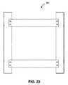
本開示技術の他の1つの態様は、フレームと、このフレーム内に配設された実質的に平坦な発光ダイオード(LED)パネルとを備えた照明器具であって、フレームは、下部アセンブリおよびこの下部センブリに結合した上部アセンブリを備え、下部アセンブリおよび上部アセンブリは、協働してフレーム内の複数のチャネルを形成し、下部アセンブリは、背面およびこの背面上にある複数の取り付けタブを備え、取り付けタブは、(i)取り付けタブが実質的に背面と同一平面にある第1の収納位置と、(ii)取り付けタブが背面に対して約90度の角度で突出している第1の突出位置と、(iii)取り付けタブが背面に対して約180度の角度で突出している第2の突出位置との間で設定される。 Another aspect of the disclosed technology is a luminaire comprising a frame and a substantially flat light emitting diode (LED) panel disposed in the frame, the frame comprising a lower assembly and the An upper assembly coupled to the lower assembly, wherein the lower assembly and the upper assembly cooperate to form a plurality of channels in the frame, and the lower assembly includes a back surface and a plurality of mounting tabs on the back surface; The tab includes (i) a first storage position where the mounting tab is substantially flush with the back surface, and (ii) a first protruding position where the mounting tab protrudes at an angle of about 90 degrees with respect to the back surface. (Iii) The mounting tab is set between a second protruding position where the mounting tab protrudes at an angle of about 180 degrees with respect to the back surface.
1つの特徴によれば、取り付けタブは、下部アセンブリの背面と一体化的に形成されている。 According to one feature, the mounting tab is integrally formed with the back surface of the lower assembly.
1つの特徴によれば、取り付けタブは、下部アセンブリの背面からの切り抜き部として形成されている。 According to one feature, the mounting tab is formed as a cut out from the back of the lower assembly.
1つの特徴によれば、取り付けタブは、下部アセンブリの背面に作動可能に結合している。 According to one feature, the mounting tab is operably coupled to the back surface of the lower assembly.
1つの特徴によれば、取り付けタブは、固締具を受け入れるように構成された開口部を形成している。 According to one feature, the mounting tab forms an opening configured to receive a fastener.
1つの特徴によれば、照明器具は、取り付けタブを用いて平坦面に取り付けられるように構成されている。 According to one feature, the luminaire is configured to be attached to a flat surface using a mounting tab.
本開示技術の他の1つの態様は、フレームと、このフレーム内に配設された実質的に平坦な発光ダイオード(LED)パネルであって、フレームは、下部アセンブリおよびこの下部アセンブリに接合した上部アセンブリを備え、下部アセンブリおよび上部アセンブリは、協働してフレーム内の複数のチャネルを形成するパネルと、平坦面に装着されるように構成された取り付け部材であって、フレームの下部アセンブリと係合するように構成された複数の係合部材を備える取り付け部材とを備えている、照明器具に関する。 Another aspect of the disclosed technology is a frame and a substantially flat light emitting diode (LED) panel disposed within the frame, the frame comprising a lower assembly and an upper portion joined to the lower assembly. The lower assembly and the upper assembly are a panel that cooperates to form a plurality of channels in the frame, and a mounting member configured to be mounted on a flat surface, the engagement with the lower assembly of the frame. It is related with the lighting fixture provided with the attachment member provided with the some engaging member comprised so that it might match.
1つの特徴によれば、係合部材は、下部アセンブリの外エッジ内のスロットと係合するように構成された複数のJフックを具備している。 According to one feature, the engagement member comprises a plurality of J hooks configured to engage slots in the outer edge of the lower assembly.
1つの特徴によれば、取り付け部材は、スライドロック機構を介してフレームの下部アセンブリと解放可能な形で係合するように構成されている。 According to one feature, the attachment member is configured to releasably engage the lower assembly of the frame via a slide lock mechanism.
1つの特徴によれば、取り付け部材は、外部接続箱と協働するように構成された中央開口部を形成している。 According to one feature, the attachment member forms a central opening configured to cooperate with the external junction box.
1つの特徴によれば、取り付け部材は、AC入力線を受け入れるように構成された中央開口部を形成している。 According to one feature, the attachment member forms a central opening configured to receive an AC input line.
本開示技術の他の1つの態様は、フレームと、このフレーム内に配設された実質的に平坦な発光ダイオード(LED)パネルであって、フレームは、下部アセンブリおよびこの下部アセンブリに接合した上部アセンブリを備え、下部アセンブリおよび上部アセンブリは、協働してフレーム内の複数のチャネルを形成するパネルと、フレーム内の複数のチャネルのうちの少なくとも1つの中に配設された電源回路であって、実質的に平坦なLEDパネルを外部AC電源に電気的に接続するように構成された電源回路と、下部アセンブリの背面に隣接して配設された中央配線路であって、外部AC電源に電気的に接続した配線を収容するように構成された中央配線路とを備えている照明器具に関する。 Another aspect of the disclosed technology is a frame and a substantially flat light emitting diode (LED) panel disposed within the frame, the frame comprising a lower assembly and an upper portion joined to the lower assembly. A lower assembly and an upper assembly are panels that cooperate to form a plurality of channels in the frame and a power supply circuit disposed in at least one of the plurality of channels in the frame. A power circuit configured to electrically connect a substantially flat LED panel to an external AC power source, and a central wiring path disposed adjacent to the back of the lower assembly, to the external AC power source The present invention relates to a luminaire comprising a central wiring path configured to accommodate electrically connected wiring.
1つの特徴によれば、中央配線路は、フレームの対面するエッジ間に配線するように構成されている。 According to one feature, the central wiring path is configured to route between facing edges of the frame.
1つの特徴によれば、中央配線路は、フレームの対面するエッジにあるチャネル内に配設された電源に、外部AC電源を電気的に接続して配線するように構成されている。 According to one feature, the central wiring path is configured to electrically connect and wire an external AC power source to a power source disposed in a channel at the facing edge of the frame.
1つの特徴によれば、中央配線路は、下部アセンブリの背面に結合した背面カバーを備えている。 According to one feature, the central wiring path includes a back cover coupled to the back surface of the lower assembly.
1つの特徴によれば、背面カバーは、外部AC電源に電気的に接続したAC入力線を受け入れるように構成された中央開口部を形成している。 According to one feature, the back cover forms a central opening configured to accept an AC input line electrically connected to an external AC power source.
1つの特徴によれば、中央開口部は、突出穴として構成されている。 According to one characteristic, the central opening is configured as a protruding hole.
本開示技術の他の1つの態様は、フレームと、このフレーム内に配設された実質的に平坦な発光ダイオード(LED)パネルであって、フレームは、下部アセンブリおよびこの下部アセンブリに接合した上部アセンブリを備え、下部アセンブリおよび上部アセンブリは、協働してフレーム内の複数のチャネルを形成するパネルと、フレーム内の複数のチャネルのうちの少なくとも1つの中に配設された電源回路であって、実質的に平坦なLEDパネルを外部AC電源に電気的に接続するように構成された電源回路と、フレーム内の複数のチャネルのうちの少なくとも1つの中に配設された配線ボックスであって、外部AC電源に電気的に接続した配線を収容するように構成された配線ボックスとを備えている、照明器具に関する。 Another aspect of the disclosed technology is a frame and a substantially flat light emitting diode (LED) panel disposed within the frame, the frame comprising a lower assembly and an upper portion joined to the lower assembly. A lower assembly and an upper assembly are panels that cooperate to form a plurality of channels in the frame and a power supply circuit disposed in at least one of the plurality of channels in the frame. A power circuit configured to electrically connect a substantially flat LED panel to an external AC power source and a wiring box disposed in at least one of the plurality of channels in the frame, The present invention relates to a lighting apparatus including a wiring box configured to receive wiring electrically connected to an external AC power source.
1つの特徴によれば、フレームの下部アセンブリは、外部AC電源からAC入力線を受け入れるように構成された開口部を形成している。 According to one feature, the lower assembly of the frame forms an opening configured to receive an AC input line from an external AC power source.
1つの特徴によれば、照明器具は、開口部の上に配設されたカバーを備え、このカバーは、外部AC電源に電気的に接続したAC入力線を受け入れるように構成された中央開口部を形成している。 According to one feature, the luminaire includes a cover disposed over the opening, the cover being a central opening configured to receive an AC input line electrically connected to an external AC power source. Is forming.
1つの特徴によれば、中央開口部は、突出穴として構成されている。 According to one characteristic, the central opening is configured as a protruding hole.
1つの特徴によれば、フレームの少なくとも1つのエッジは、配線ボックスおよびこの配線ボックスから離れた電源ボックスを形成している。 According to one characteristic, at least one edge of the frame forms a wiring box and a power supply box remote from the wiring box.
1つの特徴によれば、照明器具は、下部アセンブリの背面に隣接して配設された中央配線路を備え、中央配線路は、フレームの対面するエッジ間に配線するように構成されている。 According to one feature, the luminaire includes a central wiring path disposed adjacent to the back surface of the lower assembly, the central wiring path being configured to route between facing edges of the frame.
1つの特徴によれば、中央配線路は、フレームの1つのエッジにある配線ボックスからフレームの反対側のエッジまで配線するように構成されている。 According to one feature, the central wiring path is configured to route from a wiring box at one edge of the frame to an opposite edge of the frame.
本発明のこれらの特徴およびさらに他の特徴は、以下の説明文および添付した図面を参照すれば明らかになるであろう。説明文および図面では、本発明の特定の実施形態を、本発明の原理を用いることのできるいくつかの方法を示すものとして詳細に開示しているが、本発明が記載通りの範囲に限定されないことは理解されることである。むしろ本発明は、本明細書に添付した特許請求の範囲の精神および用語に及ぶあらゆる変更、修正および均等物を含むものである。 These and other features of the present invention will be apparent with reference to the following description and attached drawings. In the description and drawings, specific embodiments of the invention are disclosed in detail as indicating some of the ways in which the principles of the invention may be used, but the invention is not limited to the scope described. That is to be understood. Rather, the invention includes all changes, modifications and equivalents that fall within the spirit and term of the claims appended hereto.
1つの実施形態に関して説明かつ/または図示した特徴は、1つ以上の他の実施形態および/もしくは他の実施形態の特徴と組み合わせたもの、または他の実施形態の特徴の代わりに、同じようにまたは同様の方法で使用されてもよい。 Features described and / or illustrated with respect to one embodiment may be combined with one or more other embodiments and / or features of other embodiments, or instead of features of other embodiments, similarly. Or it may be used in a similar manner.
本明細書で使用した「具備する/具備している」という用語は、記載した特徴、完全なもの、ステップまたは部品を明記するために用いているのであって、1つ以上の他の特徴、完全なもの、ステップ、部品もしくはこれらを合わせたものの存在または追加を排除するものではないことを強調しておく。 As used herein, the term “comprising / comprising” is used to specify a described feature, completeness, step, or part, and includes one or more other features, It is emphasized that it does not exclude the presence or addition of complete items, steps, parts or combinations thereof.
本発明の多くの態様は、以下の図面を参照するとさらによく理解できる。図面内の部品は、必ずしも原寸通りではなく、本発明の原理を明瞭に説明することを強調するものである。同じように、1つの図面に描かれた素子および特徴は、他の図面に描かれた素子および特徴と組み合わさっていることがある。さらに、図面では、複数の図を通して同じ符号はそれに該当する部分を指している。 Many aspects of the invention can be better understood with reference to the following drawings. The parts in the drawings are not necessarily to scale, emphasis instead being placed upon clearly illustrating the principles of the present invention. Similarly, elements and features depicted in one drawing may be combined with elements and features depicted in other drawings. Further, in the drawings, the same reference numerals denote corresponding portions throughout the drawings.
本開示技術の態様を明瞭かつ簡潔に説明するにあたり、図面は必ずしも原寸通りでないことがあり、いくつかの特徴を幾分概略的な形で示しているところがある。 In describing the aspects of the disclosed technology clearly and concisely, the drawings may not necessarily be to scale, and some features may be shown in somewhat schematic form.
商業用照明システムの既存の照明器具は、安易に更新して旧式の照明器具を現代の部品を組み入れた照明器具に取り換えたり、現代の部品を一新して劣化作用を逆行させたりすることはできない。従来の蛍光照明器具および入手可能な後付けキットは、既存の照明システムを更新するのに満足のいくものではない。なぜなら、とりわけ既存の照明器具は、まず撤去されるか、または少なくとも、更新を実施できる以前に既存の照明器具から特定の部品を撤去することで大幅に修正しなければならないからである。従来の蛍光照明器具または入手可能な後付けキットを用いた後付けは、労力を要する上にプロセスが長く、これによって後付けプロセスの業務作業が著しく煩雑になっている。後付けキットによっては、部品の取り換えに使用する発光ダイオード(LED)を用いるように構成されているものもあるが、このようなキットは、より複雑な設備を必要とし、かつ/または所望の光出力がそれほど得られない。 Existing lighting fixtures in commercial lighting systems can be easily updated to replace old lighting fixtures with lighting fixtures that incorporate modern parts, or renovate modern parts to reverse degradation Can not. Conventional fluorescent lighting fixtures and available retrofit kits are not satisfactory for updating existing lighting systems. This is because inter alia existing luminaires must first be removed or at least greatly modified by removing certain parts from existing luminaires before they can be updated. Retrofitting using conventional fluorescent lighting fixtures or available retrofit kits is labor intensive and requires a long process, which greatly complicates the work of the retrofitting process. Some retrofit kits are configured to use light emitting diodes (LEDs) that are used to replace components, but such kits require more complex equipment and / or desired light output. Is not so much.
本開示は、従来の蛍光照明器具および従来の後付けキットにまつわる欠点を認識した上で、改良した照明器具、およびこれに関連する実質的に平坦なLEDパネルを含む後付けキットであって、様々な形状およびサイズに形成できる後付けキットを提供するものである。後にさらに完全に記載するように、実質的に平坦なLEDパネルは、様々な取り換え方法、独自の配設方法および後付け用途を支持する型のフォームファクタを提供する。エッジ照明を有する実質的に平坦なLEDパネルを設けることで、長さおよび幅に柔軟性があり、均一な光出力を提供する薄型パネルが構成できる。照明器具およびこれに関連する後付けキットは、極めて多用途かつ配設が簡易な装置を提供するものである。 Recognizing the shortcomings associated with conventional fluorescent lighting fixtures and conventional retrofit kits, the present disclosure is a retrofit kit including an improved lighting fixture and a substantially flat LED panel associated therewith, in various shapes. And a retrofit kit that can be formed into sizes. As described more fully below, the substantially flat LED panel provides a form factor that supports various replacement methods, unique placement methods and retrofit applications. By providing a substantially flat LED panel with edge illumination, a thin panel that is flexible in length and width and provides uniform light output can be constructed. Lighting fixtures and associated retrofit kits provide a very versatile and easy to install device.
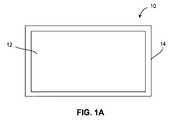
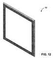
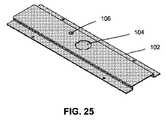
次に、図1〜9を参照すると、発光ダイオード(LED)パネル12を有する照明器具10の例示的な実施形態が示されている。1つの実施形態では、LEDパネル12は、実質的に平坦なLEDパネル(単にLEDパネルと呼ぶこともある)である。様々な実施形態の説明文と関連させて使用している「実質的に平坦なLEDパネル」という用語は、パネルの長さおよび幅よりも実質的に薄い厚みを有するLEDパネルを含むという意味である。このほか、「実質的に平坦なLEDパネル」という用語は、厚みがわずかに均一ではないLEDパネル、例えば、照明パネルの厚みよりも大きな厚みを有するフレーム(全体的に符号14で表記)を備えているLEDパネルや、フレームを備えていないLED照明パネルを含むという意味である。後にさらに完全に記載するように、照明器具およびこれに関連する実質的に平坦なLEDパネルを有する後付け照明キットを備えることで、用途が極めて多様になり、既存の蛍光灯照明ユニットに後付けする用途などの様々な用途における配設が極めて簡易になる。 Referring now to FIGS. 1-9, an exemplary embodiment of a
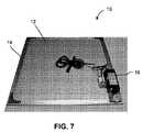
前面から実質的に平坦なLEDパネル12を見ると、パネル12は、フレーム14、およびこのフレーム14に囲まれた発光構造30に分割することができる。フレーム14は、構造を支持し、LEDストリップ片30などのLEDパネルの部品および電源回路(全体的に符号16で表記)を含み、熱放散を行う。電源回路16がLEDドライバ、一体型電源、制御回路などを備えることができることは理解されるであろう。一般に、フレーム14は細く、フレーム14の様々な要件に従ったものであることが望ましい。LEDストリップ片30に配線で接続した外付け変圧器ブロック(16)を含んでいる図7〜図8の一実施形態では、フレーム14の典型的な幅は、約4ミリメートルから約10ミリメートルの範囲であり、さらに好ましくは約4ミリメートルから約8ミリメートルの範囲である。しかしながら、これよりも著しく細いフレームを、超薄型LEDストリップ片などのコンパクトな部品と一緒に用いてもよい。これよりも幅広いフレームを、機能またはデザインを検討するために使用してもよい。例えば図6Aのフレーム14は、比較的幅のある駆動回路16を収容するために、さらに広い領域をもっている。他の1つの例として、また後にさらに完全に記載するように、フレームの外側の寸法を調整して、蛍光灯収容ユニットのカバー、またはキャビネット内部の照明設備などの囲まれた空間内にきっちり収まるようにしてもよい。フレームの外エッジおよび内エッジは、同じ形状(例えば長方形)でも異なる形状でもよい。フレームは、全辺が同じまたは実質的に同様の幅であってもよいし、図6Aのように辺によって異なる幅であってもよい。 Looking at the substantially
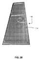
実質的に平坦なLEDパネル12を備えている照明器具10は、長方形、その他の多角形(例えば八角形)、円形および長円形のフォームファクタなどだがこれに限定されない様々な寸法およびフォームファクタであってよい。例えば、照明器具10は、サイズが約2フィート(60.96cm)×4フィート(121.92cm)(2フィート×4フィート)の長方形とすることができ、これは、標準的な蛍光灯天井反射板のうちの小さい方の例示的な寸法に相当する。他の1つの例示的な実施形態では、照明器具10は、約1フィート(30.48cm)×4フィート(121.92cm)の寸法にすることができる。さらに他の1つの例示的な実施形態では、照明器具10は、カウンタの下またはキャビネットの下を照明する用途に向けた標準の長さ((12インチ(30.48cm)、18インチ(45.72cm)、24インチ(60.96cm)、36インチ(91.44cm)など)のサイズにすることができる。後付け方法は、任意の特定サイズの蛍光灯ユニットに限定されないことは理解されるであろう。実質的に平坦なLEDパネル12は、本発明の範囲を逸脱しない限り、どのようなサイズであってもよい。このようにサイズに融通が利くことで、柔軟性が高まり、様々な用途に関連した使用ができるようになる。 The
1つの例示的な実施形態によれば、照明器具10は、フレーム14と、このフレーム14内に配設された実質的に平坦なLEDパネル12と、フレーム14内またはフレーム14に隣接して配設された電源回路(全体的に符号16で表記)とを備え、電源回路16は、実質的に平坦なLEDパネル12を外部電源(図示せず)に電気的に接続するように構成されている。実質的に平坦なLEDパネル12は、比較的薄いユニット完成品の状態で、明るく均一な光を供給するように構成することができる。例えば、1つの実施形態では、実質的に平坦なLEDパネル12の厚みは、約1.0インチ(2.54cm)未満である。他の1つの実施形態によれば、実質的に平坦なLEDパネル12の厚みは、約0.5インチ(1.27cm)未満である。 According to one exemplary embodiment, the
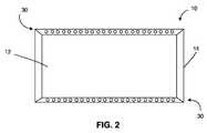
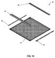
図8および図9は、実質的に平坦なLEDパネルが、フレームの少なくとも1つのエッジに隣接して配設されたエッジ照明に沿った複数の層を備えている例示的な実施形態を示す。図示した例示的な実施形態では、実質的に平坦なLEDパネルは、光透過パネル20、例えば導光板またはその他のポリカーボネート板もしくはアクリル板を備え、この板は、光透過パネル20のエッジで受け入れた光を均等に分配するように構成されている。LEDアレイ(全体的に符号30で表記)は、フレーム14の少なくとも1つのエッジおよび光透過パネル20に隣接して設けることができる。例えば、LEDストリップ片30は、フレーム14の1つのエッジに隣接して(例えば、フレーム内のチャネル内に配設されて)、かつ光透過パネル20の1つのエッジに隣接して支持してもよい。このようにする代わりに、実質的に平坦なLEDパネル12は、フレーム14の2つのエッジの中に組み入れられているか、またはこの2つのエッジに少なくとも部分的に支持されている、LEDストリップ片30を設けることができる。照明器具10が長方形のフォームファクタを有するさらに他の1つの例示的な実施形態では、実質的に平坦なLEDパネル12は、フレーム14の全4つのエッジの中に組み入れられているか、またはこの4つのエッジに少なくとも部分的に支持されているLEDストリップ片30を設けることができる。LEDのサイズおよび位置は、LED素子の「発光寸法」の厚みが、光透過パネルの光入力エッジと同じかまたはこれよりもわずかに薄くなるように決定することができ、これによって極めて薄いプロファイルが可能になる。 FIGS. 8 and 9 show an exemplary embodiment in which a substantially flat LED panel comprises multiple layers along edge illumination disposed adjacent to at least one edge of the frame. In the illustrated exemplary embodiment, the substantially flat LED panel comprises a
実質的に平坦なLEDパネル12は、散光フィルム22を設けることができ、このフィルムは、光透過パネル20の第1の辺、例えば器具が天井照明用途向けに水平に取り付けられる場合は光透過パネル20の下に設けられる。外側散光フィルム22は、均一な光出力を供給するように構成され、任意の適切な材料で作製することができる。例えば、用途がある場合、外側散光フィルム22は、耐候性フィルムとする。外側散光フィルム22は、特定の用途に応じて、軟質フィルムまたは硬質の耐摩耗性フィルムとして構成することができる。外側散光フィルム22は、所望の用途に応じて防水性または防湿性を有するように作製する。 The substantially
実質的に平坦なLEDパネル12は、輝度向上フィルム(BEF)24を設けることができ、このフィルムは、光透過パネル20の第2の辺、例えば器具が天井照明用途向けに水平に取り付けられる場合は光透過パネル20の上に設けられる。輝度向上フィルム24は、光を垂直軸に沿ってコリメートして、実質的に平坦なLEDパネル12から出力される光全体を改善するように構成されている。1つの実施形態によれば、実質的に平坦なLEDパネルは、実質的に平坦なLEDパネルの1つ以上のエッジに沿ってLEDを特定の配列にするように最適化し、複数のBEFを備えるように構成する。この例示的な実施形態では、実質的に平坦なLEDパネルは、光透過パネルを導光板の形態で設けることができ、第1のLEDアレイが、導光板の第1の辺に隣接するフレームの第1の辺に組み入れられ、この第1のLEDアレイは、第1の方向に沿って集中する光を発し、第2のLEDアレイが、導光板の第2の辺に隣接するフレームの第2の辺に組み入れられ、この第2のLEDアレイは、第1の方向とは逆方向である第2の方向に沿って集中する光を発する。実質的に平坦なLEDパネルは、導光板に隣接して配設されて、第1のLEDアレイが発する光をコリメートするように構成された第1の輝度向上フィルム(BEF)と、第1のBEFに隣接して配設されて、第2のLEDアレイが発する光をコリメートするように構成された第2のBEFとを備えさせることができる。 The substantially
図9に戻ると、実質的に平坦なLEDパネル12は、反射器26を設けることができ、この反射器は、BEF24の反対側、例えば器具が天井照明用途向けに水平に取り付けられる場合はBEF24の上に設ける。反射器26は、光透過パネル20が発する光の一部を、意図していた出力方向とは逆方向に戻すように設けられ、これによって全体の光出力を高める。図示した例示的な実施形態では、実質的に平坦なLEDパネル12は、裏板28を備え、これは例えば、反射器26の反対側に隣接して配設されるシート状の金属製裏板である。金属(例えばアルミニウム)製フレーム(14)と組み合わさったシート状金属製裏板28は、LEDが発生させる熱を良好に消散させることができる。 Returning to FIG. 9, the substantially
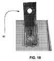
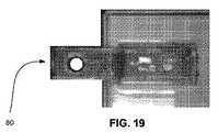
照明器具10は、フレーム14内に、フレーム14に隣接して、またはフレーム14の外側に配設された電源回路16を備え、電源回路16は、実質的に平坦なLEDパネル12を外部電源に電気的に接続するように構成されている。照明器具を蛍光灯天井照明の後付け用途に用いる1つの例示的な実施形態では、電源回路16は、ブロック型変圧器を備え、この変圧器は、外部電源に直接電気的に接続するか、蛍光灯照明ユニットに連結したソケットを介して外部電源に直接電気的に接続するか(例えば図16および図17を参照)、または蛍光灯照明ユニットに連結した安定器に直接電気的に接続するように構成されている。 The
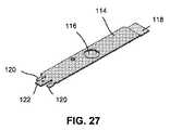
代替実施形態によれば、電源回路は、LEDドライバを設けることができ、このLEDドライバは、フレームの一部の中に組み入れられ、LEDを外部電源に電気的に接続するように構成される。この実施形態は、壁、キャビネットの下側などの平坦面に容易に取り付けることのできる極めて薄型のフォームファクタを備えた照明器具を提供する役割を果たすことが理解されるであろう。図5および図6に示したように、照明器具10は、第1および第2のLEDストリップ片30を備えるように構成することができ、このストリップ片は、フレーム14の対面する辺に、1対のLEDドライバ16の形態をした電源回路と一緒に配置され、このLEDドライバは、長方形のフレームの残りの1辺または2辺に設けられている。図示した実施形態は、第1のLEDアレイ(例えば、LEDストリップ片30)に電気的に接続され、この第1のLEDアレイを制御するように構成された第1のLEDドライバ16とともに、第2のLEDアレイ(例えばLEDストリップ片)に結合され、この第2のLEDアレイを制御するように構成された第2のLEDドライバ16を示している。 According to an alternative embodiment, the power supply circuit can be provided with an LED driver that is incorporated into a portion of the frame and is configured to electrically connect the LED to an external power source. It will be appreciated that this embodiment serves to provide a luminaire with a very thin form factor that can be easily mounted on a flat surface such as a wall, the underside of a cabinet. As shown in FIGS. 5 and 6, the
図6Aは、代替の照明器具10を示し、この照明器具は、フレーム14の対面する辺(例えば、図6に示す向きでのフレームの上側とフレームの下側)に配設された第1および第2のLEDストリップ片30と、フレームの残りの辺に配設された1対のLEDドライバ16とを備えている。この残りの辺は、LEDストリップ片を含んでいる辺よりも広く、より大きいLEDドライバ(例えばPCBを取り付けた変圧器およびその他のドライバ部品)を収容できるように形成されている。 FIG. 6A shows an
後にさらに完全に考察するように、様々な設備にうまく適合する照明キットを提供することが望まれることが理解されるであろう。一般に、平坦なLEDパネルをデザインする際は、光学スタックおよびLEDを最適化して、意図した用途の光学的な要件を満たし、想定していたフォームファクタおよび平坦なLEDパネルのドライバ仕様を念頭に置かなければならない。「普遍的な」照明キットを提供する際に、比較的容易なのは、中核となる光学アセンブリを変更することなくフレームデザインを修正して、例えば、フォームファクタまたはこれに関連する部品のバリエーションが少ない照明キットの別のバージョンを提供することである。 As will be discussed more fully later, it will be appreciated that it would be desirable to provide a lighting kit that is well adapted to various installations. In general, when designing a flat LED panel, optimize the optical stack and LEDs to meet the optical requirements of the intended application, keeping in mind the expected form factor and flat LED panel driver specifications. There must be. In providing “universal” lighting kits, it is relatively easy to modify the frame design without changing the core optical assembly, for example, lighting with less form factor or related component variations Is to provide another version of the kit.
実質的に平坦なLEDパネルは、様々な色および/または色温度の出力端子を有する複数のLEDを設けることができる。例えば、実質的に平坦なLEDパネルは、所定の色温度の出力端子を有する白色LEDを設けることができる。他の1つの実施形態によれば、実質的に平坦なLEDパネルは、複数のカラーLED(例えば、赤色出力端子、緑色出力端子および青色出力端子を有するLED)を設けることができ、このカラーLEDは、給電されると協働して白光を生成するように構成される。複数のカラーLEDの場合、照明器具は、カラーLEDに選択的に給電して可変的な色温度の光出力を供給するように構成された制御回路を備える。この制御回路は、実質的に平坦なLEDパネルが発する光の強度を制御するように構成することもでき、これによって調光機能を提供する。 A substantially flat LED panel can be provided with a plurality of LEDs having output terminals of various colors and / or color temperatures. For example, a substantially flat LED panel can be provided with a white LED having an output terminal of a predetermined color temperature. According to another embodiment, the substantially flat LED panel can be provided with a plurality of color LEDs (eg, LEDs having a red output terminal, a green output terminal, and a blue output terminal), the color LEDs Are configured to cooperate to generate white light when powered. In the case of multiple color LEDs, the luminaire includes a control circuit configured to selectively power the color LEDs to provide a light output with a variable color temperature. The control circuit can also be configured to control the intensity of light emitted by the substantially flat LED panel, thereby providing a dimming function.
1つの実施形態によれば、実質的に平坦なLEDパネルは、フレームの少なくとも1つのエッジに隣接して配設されたLEDストリップ片を1つ以上備え、このLEDストリップ片は、適切な電気コネクタを介して電源回路に取り外し可能なように接続される。この構成により、実質的に平坦なLEDパネル内にある1つ以上のLEDストリップ片を容易に取り換えられることが理解されるであろう。例えば、LEDが故障したり焼損したりした場合でも、LEDストリップ片は、器具全体を取り換えることなく容易に取り換えることができる。このほか、照明器具の色出力は、LEDストリップ片を1つ以上交換することで変更できる。例えば、白色LEDのストリップ片を取り除き、白色LEDのストリップ片をカラーLEDに取り換えることで、イルミネーション効果を達成できる。 According to one embodiment, the substantially flat LED panel comprises one or more LED strip pieces disposed adjacent to at least one edge of the frame, the LED strip pieces comprising a suitable electrical connector. It is detachably connected to the power supply circuit via It will be appreciated that this configuration allows for easy replacement of one or more LED strip pieces in a substantially flat LED panel. For example, even if the LED fails or burns out, the LED strip piece can be easily replaced without replacing the entire instrument. In addition, the color output of the luminaire can be changed by replacing one or more LED strip pieces. For example, the illumination effect can be achieved by removing the strip pieces of white LEDs and replacing the strip pieces of white LEDs with color LEDs.
平坦なLEDパネル内のLEDストリップ片を1つ以上取り換えるのを容易にするために、フレームには、取り外しできるか、あるいは残りのフレームから分離できる1つ以上のセクションを設けることができる。例えば、LEDストリップ片を含んでいるフレームのカバーセクションは、残りのフレームに対するヒンジ式接続部、および引っ張りタブを設けていてよい。ユーザは、フレームのカバーセクションを引っ張って開けて、取り換えのためにLEDストリップ片のカバーを取る。 To facilitate replacing one or more LED strip pieces in a flat LED panel, the frame can be provided with one or more sections that can be removed or separated from the rest of the frame. For example, the cover section of the frame containing the LED strip pieces may be provided with a hinged connection to the remaining frame and a pull tab. The user pulls open the cover section of the frame and covers the LED strip piece for replacement.
1つの実施形態によれば、照明器具は、フレームを支持面に取り付ける(例えば取り外し可能なように、または恒久的に取り付ける)ように構成された少なくとも1つの取り付け部材を備えている。取り付け部材は、所望の用途に応じて多数の形態をとってよいことが理解されるであろう。例えば、取り付け部材は、フレームを、壁などの実質的に垂直な支持面に取り付けるように構成することができる。この場合、取り付け部材は、照明器具を家の内壁、ホテルの内壁、ガレージの内壁などに固定するように構成された適切なクリップ、ブラケットなどを設ける。他の1つの例示的な実施形態では、取り付け部材は、フレームを、天井、キャビネットの下側などの実質的に水平な支持面に取り付けるように構成することができる。その他の用途例としては、吹き抜け照明、非常用照明(任意にバッテリのバックアップを含む)、小室用のタスク照明、カウンタ下の照明(例えば、台所の作業領域および食器棚内の照明)、家庭用または商業用のガレージ照明、小売店の棚用の照明、水槽の照明などがあるが、これらに限定されない。後にさらに完全に記載するように、照明器具は、既存の蛍光灯照明ユニットに後付けするための後付けキットに用いることができる。 According to one embodiment, the luminaire comprises at least one attachment member configured to attach the frame to the support surface (eg, to be removable or permanently attached). It will be appreciated that the attachment member may take a number of forms depending on the desired application. For example, the attachment member can be configured to attach the frame to a substantially vertical support surface such as a wall. In this case, the mounting member is provided with a suitable clip, bracket or the like configured to secure the luminaire to the interior wall of the house, the interior wall of the hotel, the interior wall of the garage, or the like. In another exemplary embodiment, the attachment member can be configured to attach the frame to a substantially horizontal support surface, such as a ceiling, the underside of a cabinet, or the like. Other application examples include atrium lighting, emergency lighting (optionally including battery backup), task lighting for small rooms, lighting under counters (eg lighting in kitchen work areas and cupboards), home use Or commercial garage lighting, retail shelf lighting, aquarium lighting, and the like. As described more fully below, the luminaire can be used in a retrofit kit for retrofitting an existing fluorescent lamp lighting unit.
取り付け部材は、用途に合わせることができる。平坦なLEDパネルがメンテナンスまたは取り換えのために全体を撤去されることが予想される用途では、分解可能な取り付け部材を選択すべきである。一方、通常は平坦なLEDパネル全体を撤去しないと予想されるが、LEDストリップ片などの部品を取り換えるメンテナンスをする可能性がある場合、最も重要な検討事項は、取り付けの物理的な安全対策であろう。例えば、蛍光灯天井照明器具に表面実装するように設計された平坦なLEDパネルの後付けキットの場合、地震の安全基準を満たしている安全な取り付け方法を用いるべきである。 The attachment member can be adapted to the application. In applications where a flat LED panel is expected to be removed entirely for maintenance or replacement, a dismountable mounting member should be selected. On the other hand, it is normally expected that the entire flat LED panel will not be removed, but if there is a possibility of maintenance to replace parts such as LED strip pieces, the most important consideration is physical safety measures for installation. I will. For example, in the case of a retrofit kit for a flat LED panel designed to be surface mounted to a fluorescent ceiling luminaire, a safe mounting method that meets earthquake safety standards should be used.
照明器具は、複数の照明器具と一緒に配列および/または配設されることができ、この場合、主要な照明器具は、外部電源に電気的に接続され、その他の照明器具は、主要な照明器具を用いて外部電源に接続する(いわゆる「デイジーチェーン接続」)ことができることが理解されるであろう。 The luminaire can be arranged and / or arranged with a plurality of luminaires, in which case the main luminaire is electrically connected to an external power source and the other luminaires are connected to the main luminaire. It will be appreciated that the appliance can be used to connect to an external power source (so-called “daisy chain connection”).
次に、図10〜図35を見ながら、照明器具10を壁などの平坦面、駐車場内などの天井、キャビネットの下側などに容易に取り付けることのできる実施形態について考察していく。これらの特徴および実施形態について、照明器具を平坦面に取り付ける方法に関連付けて考察するが、これらの特徴は、後付け用途にも同じように適用可能であることは理解されるであろう。これらの実施形態では、電源回路は、フレーム14の一部の中に組み入れられるか、あるいはこの中に配置することができる。ただし、これらの実施形態は、外部電源と一緒に用いられてもよいことは理解すべきである。 Next, with reference to FIGS. 10 to 35, an embodiment in which the
本願で考察したその他の1つ以上の実施形態と一緒に実装してよい1つの実施形態によれば、フレームは、下部アセンブリ60(下部フレームアセンブリ、下部パネルまたは下部パネルアセンブリとも呼ぶ)およびこの下部アセンブリ60に(例えば、ネジなどの適切な固締具により、またはスナップフィットにより)作動可能に結合した上部アセンブリ62(上部フレームアセンブリ、上部パネルまたは上部パネルアセンブリとも呼ぶ)を備えている。後にさらに完全に考察するように、下部アセンブリ60および上部アセンブリ62は、協働してフレーム内に複数のチャネルを形成する。これらのチャネルは、電源回路(電源およびこれに関連する駆動回路を含む)、配線、LEDアレイなどを収容あるいは支持できる。 According to one embodiment that may be implemented together with one or more other embodiments discussed herein, the frame includes a lower assembly 60 (also referred to as a lower frame assembly, a lower panel, or a lower panel assembly) and a lower portion thereof. The
前述したように、下部アセンブリ60に作動可能に結合した上部アセンブリ62でできたフレーム14は、本発明の範囲を逸脱しない限り、様々なフォームファクタおよび寸法を採用してよい。例えば、フレームは、約2フィート(60.96cm)×約2フィート(60.96cm)(2フィート×2フィート)、約1フィート(30.48cm)×約2フィート(60.96cm)(1フィート×2フィート)、約1フィート(30.48cm)×約4フィート(121.92cm)(1フィート×4フィート)などにすることができる。 As previously described, the
下部アセンブリ60は、下部アセンブリの中央領域が、実質的に平坦なLEDパネル12の光学部品の背後にわたって配設されるように構成される。下部アセンブリ60は、下部パネル62を備え、この下部パネルは、下部パネル62の内側エッジ内に1つ以上のブラケット66、68を受け入れるように構成されており、これによって下部アセンブリ60を形成する。 The
例えば、図10に示した例示的な実施形態は、下部パネルの2つの対面するエッジ(例えば、電源および/または駆動回路を収容あるいは支持するエッジ)にある1対のブラケット66を示している。図示した例示的な実施形態では、下部アセンブリ60の他の2つの対面するエッジは、LEDストリップ片またはアレイを支持するように構成された1対の内側ブラケット68を備えている。後にさらに完全に考察していくように、下部パネル62は、これに連結される取り付け板またはその他の取り付け構造の係合部材を受け入れるように構成された2セットのスロットを備えるあるいは形成することができる。 For example, the exemplary embodiment shown in FIG. 10 shows a pair of
図13は、内側ブラケット66の第1の対の例示的な実施形態を示す。内側ブラケット66の第1の対の各々の内側ブラケット66は、フレームの対面するエッジに電源を含んでいるチャネルのエッジ面となる下部を形成するように構成されている。図13に示した実施形態では、L型内側ブラケット66の狭い方の脚部は、照明器具の背後で電源ボックスを中央領域から分離するように構成されている。中央スロット70は、開口部となり、この開口部にAC入力線を通して電源ボックスとフレームアセンブリの中央領域との間を配線する。例えば、この線は、この穴を通って中央配線路に配線することができる(これについては後にさらに完全に記載)。内側ブラケット両端の切り欠き領域は、開口部となるように構成され、この開口部を通して電源から来るDC出力線を配線して、フレームの他の2つのエッジにあるLEDストリップ片に接続する。 FIG. 13 illustrates an exemplary embodiment of a first pair of
図14は、内側ブラケット68の第2の対の例示的な実施形態を示す。図示した例示的な実施形態では、各々のブラケット68は、下部パネル62と協働してLEDストリップ片を保持し、LEDストリップ片をフレームの1つのエッジに取り付けるように構成されている。各々の内側ブラケットに凹状領域72があることで、内側ブラケットを取り付けてフレームアセンブリの辺に係合させることができる。下部パネルの内エッジにある係合部材は、各々の内側ブラケット68の凹状領域72に係合できる。 FIG. 14 illustrates an exemplary embodiment of a second pair of
1つ以上の実施形態によれば、下部アセンブリ62は、1つ以上の取り付けタブ80を設けることができる。取り付けタブ80は、下部アセンブリ60の一部(例えば、可動式または再配置可能な下部アセンブリ60の切り抜き部分)と一体的に形成することができる。このようにする代わりに、取り付けタブ80は、下部アセンブリ60に作動可能に結合されてもよい。図15〜図19に示したように、取り付けタブ80は、少なくとも3つの位置のうちの1つに位置付けされるように構成することができ、3つの位置とは、(1)収納位置、中立位置または初期位置(図15)、(2)90度の位置(下部アセンブリの背面に対して約90度の角度で折れ曲がっているかあるいは設置されている位置)(図16および図18)、および(3)180度の位置(下部アセンブリの背面に対して約180度の角度で折れ曲がっているかあるいは設置されている位置)(図17および図19)である。 According to one or more embodiments, the
取り付けタブ80は、長方形の形状でもよいし、または別の都合のよい形状であってもよい。図18〜図19からわかるように、取り付けタブ80は、ネジなどの適切な固締具を受け入れるように形成された取り付け開口部82を備えているかあるいは形成している。取り付けタブ80は、90度の位置にある取り付けタブにワイヤーハンガーを固定して、吊り下げ照明器具になるようにするなどして、他の固締具と協働するように構成してもよいことは理解されるであろう。また、取り付けタブを備えることで、照明器具から180度の位置に延出している取り付けタブに貫通させたネジを使用して照明器具を壁面に固定するなどして、取り付け固締具を照明器具のフレームに貫通させることなく、照明器具を平坦面に向かって取り付けることが可能になることも理解されるであろう。 The mounting
このようにする代わりに、取り付けタブ以外の機構(蛍光灯収容ユニット内への後付けなど)を使用して照明器具を支持面に取り付ける実施形態では、取り付けタブは、取り付け開口部にワイヤーを挿入して照明器具を固定して、耐震基準を満たすために使用してもよい。 Instead of this, in embodiments where the luminaire is attached to the support surface using a mechanism other than the attachment tab (such as retrofitting into the fluorescent light housing unit), the attachment tab inserts the wire into the attachment opening. The lighting fixture may be fixed and used to meet earthquake resistance standards.
本願で考察した1つ以上の他の実施形態と一緒に実装してよい他の1つの例示的な実施形態によれば、照明器具は、照明器具を平坦面に取り付けるための取り付け板90の例示的な実施形態である取り付け部材を備えるか、あるいはこの取り付け部材に連結することができる。取り付け板は、フレームの下部アセンブリのサイズおよびフォームファクタとおよそ一致するサイズおよびフォームファクタになることは理解されるであろう。 According to another exemplary embodiment that may be implemented with one or more other embodiments discussed herein, the luminaire is an illustration of a mounting
取り付け板は、壁、天井またはキャビネットの下側などの取り付け面に固定するかあるいは留めるように構成されている。例えば、図20に示すように、取り付け板は、ネジなどの適切な固締具を受け入れるのに適した複数の取り付け開口部92を備えるかあるいは形成する。取り付け板90は、下部アセンブリ60と協働してこの下部アセンブリと解放可能な形で係合して(例えば、スライドロック機構を用いて)、照明器具を平坦面に取り付けるように構成されている。例えば、図20〜図22に示すように、取り付け板90は、複数の係合部材94(例えば、取り付け板の対面するエッジで対になったJフック)を設けることができる。これらの係合部材94は、(例えば、スライドロックの関係を介して)下部パネルの外側エッジで一連のスロットと係合するように構成することができる。ユーザは、最初に取り付け板を面に固定することで、取り付け板を用いてこの面に照明器具を取り付け、その後、照明器具を取り付け板に係合させる。 The mounting plate is configured to be secured or fastened to a mounting surface such as a wall, ceiling or underside of the cabinet. For example, as shown in FIG. 20, the mounting plate comprises or forms a plurality of mounting
取り付け板90は、中央開口部96を設けて中央に配線を入れる箇所を設けるように構成することができる。中央開口部96は、外部接続箱(例えば、天井に既存の外部接続箱)に当接するようなサイズに構成されている。1つの実施形態によれば、取り付け板90は、照明器具の背面でカバーとして機能させることができる。 The
取り付け部材は、他の形態であってもよいことは理解されるであろう。例えば、図23に示すように、取り付け部材98は、複数部材からなる構造の形態であってもよい。取り付け部材は、前述したような係合部材を設けることができる。取り付け部材98は、図21に関して前述した取り付け部材のように、中央開口部も形成している。この構成は、より柔軟で軽量な取り付けの選択肢を提供できることが理解されるであろう。本開示技術の範囲を逸脱しない限り、他の取り付け部材の構成を用いてもよい。 It will be appreciated that the attachment member may take other forms. For example, as shown in FIG. 23, the
図20〜図23に関して記載したような取り付け部材を備えることで、照明器具を取り付けたときは、取り付け機構がユーザには見えなくなるという表面の見栄えがよい取り付けが可能になることが理解されるであろう。 It will be appreciated that by providing an attachment member as described with respect to FIGS. 20-23, a surface-appropriate attachment is possible when the luminaire is attached so that the attachment mechanism is not visible to the user. I will.
次に、図24〜図25を見ると、本願で考察した1つ以上の他の実施形態と一緒に実装してもよい他の1つの例示的な実施形態によれば、下部アセンブリは、中央配線路(全体的に符号100で表記)を備えるように構成することができる(図11も参照)。中央配線路100は、AC入力線を受け入れて装着するとともに、AC入力線を単一の電源または中央配線路100の両端にある複数の電源に(電源が複数の場合はその電源同士の間に)配線するための配線経路として作用するための場所を提供するように構成されている。 Turning now to FIGS. 24-25, according to another exemplary embodiment that may be implemented in conjunction with one or more other embodiments discussed herein, the lower assembly is A wiring path (generally denoted by reference numeral 100) can be provided (see also FIG. 11). The
中央配線路100は、下部アセンブリの背面に作動可能に結合した保護カバー102で形成することができる。1つの実施形態によれば、中央配線路100は、外部AC電源に電気的に接続されたAC入力線を受け入れるように形成された突出穴などの中央開口部104を備えるかあるいは形成する。他の1つの実施形態によれば、中央配線路100は、中央開口部のない状態であってもよい。 The
保護カバー102は、下部アセンブリの背面と協働して、フレームのエッジへまたはエッジから配線するためのチャネルを提供することができる。例えば、1セットのAC配線(アース用と電源用)は、中央配線路を通ってフレームの1つのエッジにある電源につなげることができる。2つの電源がフレームの対面するエッジにある一実施形態では、別の1セットのAC配線をその電源から逆方向に戻って配線して、フレームの反対側のエッジにある第2の電源にAC電力を供給することができる。このようなAC入力線の配置にすると、フレームの1つのエッジに電源があるか、または2つの対面するエッジに電源がある照明器具の構成と適合可能になるため、柔軟な設計ができることが理解されるであろう。 The
代替実施形態では、中央配線路内のAC配線は、スプリッタを設けることができる。これによって、2セットのAC電源配線を提供し、この配線を中央開口部から両方向に配線してAC電源を両電源に供給でき、電源間に追加の配線をする必要がない。 In an alternative embodiment, the AC wiring in the central wiring path can be provided with a splitter. As a result, two sets of AC power supply wiring can be provided, and the wiring can be supplied in both directions from the central opening to supply the AC power to both power supplies. There is no need to provide additional wiring between the power supplies.
中央配線路100は、中央開口部104の脇に、中央配線路を通って配線したAC配線を接地するための接地ネジ106を設けることができる。 In the
次に、図26〜図31を見ると、本願で考察した1つ以上の実施形態と組み合わせてよい他の1つの例示的な実施形態によれば、フレーム14は、配線ボックス110を備えるように構成され、この配線ボックスがフレームのエッジでAC配線を受け入れる。配線ボックス110は、フレームの一部に適合するサイズであるシェルまたはその他の保護構造体を設けることができる。フレームの下部アセンブリの背面の一部は、配線ボックス110のサイズおよび形状とおよそ一致する開口部112(アクセス用開口部とも呼ぶ)を形成できる。配線ボックス110は、突出穴(突出開口部とも呼ぶ)116または外部電源からAC電力を受け入れるためのその他の開口部を有するカバー(突出ブラケットとも呼ぶ)114を設けることができる。フレームは、フレームの他のエッジへまたは他のエッジから配線するための(中央開口部のない)中央配線路を備えるように構成することができることが理解されるであろう。 Next, referring to FIGS. 26-31, according to another exemplary embodiment that may be combined with one or more embodiments discussed herein, the
突出ブラケット114は、配線ボックス110へのアクセスを提供し、配線ボックス110の外部にあるACケーブルを入れる場所を提供して、接続箱のカバーのように作用する。突出ブラケットを介して照明器具に結合できるAC電線管の例が、商標名Romex(商標)を使用して供給され、広く使用されている非金属の被覆ケーブルである。この種のケーブルは、突出ナットを用いて突出ブラケットの突出部内に固定することができる。突出ブラケット114は、突出開口部116に隣接する接地ネジを設けることができる。 The protruding
1つの例示的な実施形態によれば、突出ブラケット114は、アクセス開口部内で、下向きにずれたフランジ118によって一方の端部を固定し、下向きにずれたフォーク120によって他方の端部を固定することができ、フォークは、このフォークの間に開口部のあるタブ122を備え、このタブは、ブラケットの主な胴部と実質的に同一平面上にある。例示的な実施形態によれば、下部パネルのエッジにある切り抜き部(アクセス開口部)内に突出ブラケット114を挿入するために、ユーザは、アクセス開口部の1辺に隣接する平坦な照明具の背面パネルの下にフランジ118を挿入し、ブラケットの他方の端部をアクセス開口部の切り抜き部の中で回転させ、その後、突出ブラケットのフォーク状端部120をアクセス開口部の切り抜き部の他方の端部の下にスライドさせ、開口部のあるタブ122がパネルのエッジ面の上に残る状態にする。このようにすると、突出ブラケット114は、開口部のあるタブでネジを用いて下部パネルアセンブリに固定することができる。 According to one exemplary embodiment, the protruding
突出ブラケットは、配線ボックスをカバーして保護し、外部ケーブルも配線ボックス内のAC配線も支持するための頑丈な構造を提供することが理解されるであろう。突出ブラケットは、接続箱のカバーに使用された材料と同様の材料、その他の任意の適切な材料で作製される。 It will be appreciated that the protruding brackets cover and protect the wiring box and provide a sturdy structure for supporting external cables as well as AC wiring within the wiring box. The protruding bracket is made of a material similar to that used for the cover of the junction box, or any other suitable material.
図24〜図25の中央配線路100および図26〜図29のエッジ配線ボックス110は、AC入力線を受け入れ、照明器具内の電源に配線するための設計上の選択肢を提供するものである。例えば、中央配線路は、AWG(アメリカンワイヤゲージ)システムに応じて16本のゲージ線または18本のゲージ線を受け入れて配線するように構成することができる。この配線は、公称直径が0.102〜0.129cmの範囲であり、定格の電流容量(安全に電流が流れるアンペア容量)が10〜13ampsとなっており、これは、例えば北米で使用される120ボルトのAC電源の供給など、住宅用電力設備に適したものである。他の1つの例として、頑丈な接続箱のような構成をしたエッジ配線ボックスは、公称直径がおよそ0.205cmであり、定格容量が23ampsであるこれよりも重い12本のゲージ線(AWG)を受け入れてもよい。この配線は、例えば北米の商業用照明および工業用照明に一般的な、277ボルトのAC電源の供給など、商業用電力設備で使用されることが多い。 The
本願に記載した1つ以上の他の実施形態と組み合わせてよい。図30〜図33に示した例示的な実施形態によれば、下部アセンブリ130は、(内側ブラケット132および下部パネル136によって少なくとも部分的に形成された)電源用の2つのチャネルに、内側チャネル分割器134を設けることができ、この分割器は、電源用コンパートメントとAC入力線用コンパートメントとの間のフレームの1つのエッジ内でチャネルを分割し、この1つのコンパートメントを互いに隔離する。1つの実施形態によれば、この分割器134は、フレームの1つのエッジ内の中央からずれて位置し、配線ボックスよりも電源の方が長いコンパートメントを提供する。 It may be combined with one or more other embodiments described herein. In accordance with the exemplary embodiment shown in FIGS. 30-33, the
この例示的な実施形態では、内側ブラケット132は、内側チャネルまたはシェルを形成し、これが配線を配線ボックス内に閉じ込め、配線ボックスおよび電源ボックスを外力から保護する。シェルは、その内壁面にスロットを設けて、AC配線がシェルから中央配線路まで通れるようにしている。 In this exemplary embodiment, the
寸法が2フィート(60.96cm)×2フィート(60.96cm)の例示的なフレームに関して上記の特徴を記載したが、同様の構成を、1フィート(30.48cm)×1フィート(30.48cm)、1フィート(30.48cm)×2フィート(60.96cm)、1フィート(30.48cm)×4フィート(121.92cm)など、他の寸法およびフォームファクタ向けに使用できることは理解されるであろう。例えば、図34は、1フィート(30.48cm)×2フィート(60.96cm)の照明器具に対する例示的下部アセンブリを示す。このフレームアセンブリの特徴は、寸法を除いて、前述の2フィート(60.96cm)×2フィート(60.96cm)の実施形態の特徴と全般的に同じである。この例示的な実施形態では、LEDストリップ片は、フレームの長い方のエッジに沿って広がっているのに対し、電源はフレームの短い方のエッジに沿って広がっている。 Although the above features have been described for an exemplary frame measuring 2 feet (60.96 cm) by 2 feet (60.96 cm), a similar configuration can be obtained by 1 foot (30.48 cm) by 1 foot (30.48 cm). It is understood that it can be used for other dimensions and form factors, such as 1 foot (30.48 cm) × 2 feet (60.96 cm), 1 foot (30.48 cm) × 4 feet (121.92 cm), etc. I will. For example, FIG. 34 shows an exemplary lower assembly for a 1 foot (30.48 cm) by 2 foot (60.96 cm) luminaire. The features of this frame assembly are generally the same as the features of the 2 foot (60.96 cm) by 2 foot (60.96 cm) embodiment described above, except for the dimensions. In this exemplary embodiment, the LED strip pieces extend along the longer edge of the frame, while the power supply extends along the shorter edge of the frame.
図35は、例示的な1フィート(30.48cm)×4フィート(121.92cm)の照明器具に対する下部アセンブリを示す。この例示的な実施形態では、下部パネルの短い方のエッジには部品がない。これらのエッジにあるエッジブラケットは、実質的に平坦なLEDパネルに対する構造的なバリアの役割を果たしているだけである。この例示的な実施形態では、寸法の長いエッジ領域のうちの一方は、反対側の寸法の長いエッジ領域よりも幅が広い。なぜならこのエッジ領域のうちの一方は、2つの電源を支持しているのに対し、他方のエッジ領域は1対のLEDストリップ片を支持しているからである。 FIG. 35 shows the lower assembly for an exemplary 1 foot (30.48 cm) by 4 foot (121.92 cm) luminaire. In this exemplary embodiment, there is no part at the shorter edge of the bottom panel. The edge brackets at these edges only serve as a structural barrier to the substantially flat LED panel. In this exemplary embodiment, one of the long dimension edge regions is wider than the opposite dimension long edge region. This is because one of the edge regions supports two power supplies while the other edge region supports a pair of LED strip pieces.
前述したように、実質的に平坦なLEDパネルは、多数の用途に取り入れることができる。例えば、ここで図36〜図46を見ながら、後付け照明キット、および例えば蛍光灯天井照明器具(「反射板」)などの蛍光灯収容ユニットへの後付け方法を説明する。後付け照明キットは、多用途であることが理解されるであろう。例えば、後付け照明キットは、標準の散光器である反射板(例えば図36を参照)と一緒に、また、アルミめっきした反射器である反射板と一緒に用いられることができる。 As previously mentioned, a substantially flat LED panel can be incorporated into a number of applications. For example, referring to FIGS. 36 to 46, a retrofit method for retrofit lighting kits and a fluorescent lamp housing unit such as a fluorescent lamp ceiling luminaire (“reflector”) will be described. It will be appreciated that the retrofit lighting kit is versatile. For example, a retrofit lighting kit can be used with a reflector that is a standard diffuser (see, eg, FIG. 36), and with a reflector that is an aluminized reflector.
考察する目的で、後付けする蛍光灯照明ユニットは、収容ユニットと、1つ以上の蛍光灯ソケットと、この収容ユニット内に配置される安定器とを備えていることが理解されるであろう。また、説明する目的で、後付けする蛍光灯収容ユニットは、上部展開部または上部分および下部展開部または下部分を備えている。蛍光灯収容ユニットの下部展開部は、所与の形状およびサイズである周縁を備えている。例えば、この周縁は、標準の蛍光灯天井反射板にみられるように、約2フィート(60.96cm)×4フィート(121.92cm)(2フィート×4フィート)とすることができる。他の1つの例示的な実施形態では、周縁は、1フィート(30.48cm)×4フィート(121.92cm)とすることができる。さらに他の1つの例示的な実施形態では、周縁は、4フィート(121.92cm)×4フィート(121.92cm)とすることができる。後付け方法は、特定サイズの蛍光灯ユニットに限定されない。実質的に平坦なLEDパネルは、本発明の範囲を逸脱しない限り、どのようなサイズであってもよい。 For purposes of discussion, it will be understood that a retrofit fluorescent lamp illumination unit includes a storage unit, one or more fluorescent light sockets, and a ballast disposed within the storage unit. For the purpose of explanation, the fluorescent lamp housing unit to be retrofitted includes an upper development part or upper part and a lower development part or lower part. The lower unfolding part of the fluorescent lamp housing unit has a peripheral edge having a given shape and size. For example, the perimeter can be about 2 feet (60.96 cm) by 4 feet (121.92 cm) (2 feet by 4 feet), as found in a standard fluorescent ceiling reflector. In another exemplary embodiment, the perimeter can be 1 foot (30.48 cm) by 4 feet (121.92 cm). In yet another exemplary embodiment, the perimeter can be 4 feet (121.92 cm) by 4 feet (121.92 cm). The retrofitting method is not limited to a specific size fluorescent lamp unit. The substantially flat LED panel may be of any size without departing from the scope of the present invention.
後付けキットおよび後付け方法を、立体形状および構成が異なる反射板に関して記載しているが、後付けキットの好適な実施形態では、後付けキットを様々に異なる反射板に取り付けるのに適切なハードウェアを備えて、実際に「普遍的な」取り付けキットを提供する。 Although the retrofit kit and the retrofit method are described with respect to reflectors having different three-dimensional shapes and configurations, the preferred embodiment of the retrofit kit comprises hardware suitable for attaching the retrofit kit to a variety of different reflectors. In fact, provide a “universal” mounting kit.
照明キット(後付けキットとも呼ぶ)は、形状およびサイズがおよそ収容ユニットの下部展開部の周縁の所与の形状およびサイズである実質的に平坦な発光ダイオード(LED)パネルと、この実質的に平坦なLEDパネルを電源に電気的に接続するように構成された電源回路と、実質的に平坦なLEDパネルを蛍光灯照明ユニットの収容ユニットに結合するように構成された少なくとも1つの係合部材とを備えている。 The lighting kit (also referred to as a retrofit kit) is a substantially flat light emitting diode (LED) panel whose shape and size is approximately a given shape and size at the periphery of the lower deployment portion of the receiving unit, and this substantially flat A power circuit configured to electrically connect the LED panel to the power source, and at least one engagement member configured to couple the substantially flat LED panel to the housing unit of the fluorescent lighting unit; It has.
実質的に平坦なLEDパネルは、上記の1つ以上の特徴を用いる。実質的に平坦なLEDパネルは、形状およびサイズがおよそ蛍光灯収容ユニットの下部展開部の周縁の所与の形状およびサイズであるフレームを備えている。前述したように、実質的に平坦なLEDパネルは、フレームを備えるとともに、このフレームの少なくとも1つのエッジに隣接して配置されたエッジ照明に沿った複数の層も設けることができる。例えば、実質的に平坦なLEDパネルは、光透過パネルと、フレームの少なくとも1つのエッジおよび光透過パネルに隣接して配置されたLEDアレイと、光透過パネルの下に設けた散光フィルムと、光透過パネルの上に配置された輝度向上フィルム(BEF)と、BEFの上に設けた反射器とを備えている。 A substantially flat LED panel uses one or more of the features described above. The substantially flat LED panel comprises a frame whose shape and size is approximately the given shape and size of the periphery of the lower development of the fluorescent lamp housing unit. As previously mentioned, a substantially flat LED panel may comprise a frame and may also be provided with a plurality of layers along edge illumination disposed adjacent to at least one edge of the frame. For example, a substantially flat LED panel includes a light transmissive panel, an LED array disposed adjacent to the at least one edge of the frame and the light transmissive panel, a diffuse film provided under the light transmissive panel, a light A brightness enhancement film (BEF) disposed on the transmissive panel and a reflector provided on the BEF are provided.
実質的に平坦なLEDパネルは、光透過パネル、例えば、導光板またはその他のポリカーボネート板もしくはアクリル板であって、光透過パネルのエッジで受けた光を均等に分配するように構成されているパネルを備えている。LEDアレイは、フレームの少なくとも1つのエッジおよび光透過パネルに隣接して設けている。例えば、LEDストリップ片は、フレームの1つのエッジに隣接して(例えば、フレームのチャネル内に配置されて)、かつ光透過パネルの1つのエッジに隣接して支持されている。このようにする代わりに、実質的に平坦なLEDパネルは、フレームの2つのエッジの中に組み入れられているか、またはこの2つのエッジによって少なくとも部分的に支持されているLEDストリップ片を設けることができる。照明器具が長方形のフォームファクタを有するさらに他の1つの例示的な実施形態では、実質的に平坦なLEDパネルは、フレームの全4つのエッジの中に組み入れられているか、またはこの4つのエッジによって少なくとも部分的に支持されているLEDストリップ片を設ける。LEDのサイズおよび位置は、LED素子の「発光寸法」の厚みが、光透過パネルの光入力エッジと同じかまたはこれよりもわずかに薄くなるように決定することができ、これによって極めて薄いプロファイルが可能になる。 A substantially flat LED panel is a light transmissive panel, such as a light guide plate or other polycarbonate or acrylic plate, configured to evenly distribute light received at the edges of the light transmissive panel It has. The LED array is provided adjacent to at least one edge of the frame and the light transmissive panel. For example, the LED strip piece is supported adjacent to one edge of the frame (eg, disposed within the channel of the frame) and adjacent to one edge of the light transmissive panel. Instead, the substantially flat LED panel may be provided with LED strip pieces that are incorporated into or at least partially supported by the two edges of the frame. it can. In yet another exemplary embodiment where the luminaire has a rectangular form factor, the substantially flat LED panel is incorporated into or by all four edges of the frame. An LED strip piece that is at least partially supported is provided. The size and position of the LED can be determined such that the “light emitting dimension” thickness of the LED element is the same or slightly thinner than the light input edge of the light transmissive panel, thereby creating a very thin profile. It becomes possible.
1つの実施形態によれば、少なくとも1つの係合部材は、実質的に平坦なLEDパネルを収容ユニットの周縁の上に結合するように構成されている。例えば、後付けキットは、収容ユニットの周縁の上にスナップオン方式による取り付けを容易にするクランプを設ける。 According to one embodiment, the at least one engagement member is configured to couple a substantially flat LED panel on the periphery of the receiving unit. For example, a retrofit kit provides a clamp that facilitates snap-on attachment on the periphery of the storage unit.
他の1つの実施形態によれば、少なくとも1つの係合部材は、実質的に平坦なLEDパネルを収容ユニットの下部展開部の周縁内に結合するように構成されている。例えば、後付けキットは、収容ユニットの下部展開部の周縁内への取り付けを容易にするために適切なテンションクランプまたはホールドダウンクランプを設けることができる。このようにする代わりに、実質的に平坦なLEDパネルのフレームは、クランプなどの追加の固定具を使用することなく、収容ユニットの下部展開部の周縁に嵌まるようなサイズにする。この実施形態では、収容ユニットの下部展開部の周縁は、厚みのあるチャネルを設けることができ、実質的に平坦なLEDパネルの厚みは、蛍光灯収容ユニットの下部展開部の周縁沿いのチャネルの厚みとおよそ等しくなる。 According to another embodiment, the at least one engagement member is configured to couple the substantially flat LED panel within the periphery of the lower deployment portion of the receiving unit. For example, the retrofit kit can be provided with a suitable tension clamp or hold-down clamp to facilitate attachment within the periphery of the lower deployment portion of the storage unit. Instead, the substantially flat frame of the LED panel is sized to fit around the perimeter of the lower deployment portion of the receiving unit without the use of additional fixtures such as clamps. In this embodiment, the peripheral edge of the lower development part of the housing unit can be provided with a thick channel, and the thickness of the substantially flat LED panel is that of the channel along the peripheral edge of the lower development part of the fluorescent lamp housing unit. Approximately equal to the thickness.
1つの実施形態では、少なくとも1つの係合部材は、実質的に平坦なLEDパネルを収容ユニットの下部展開部にヒンジを用いて取り付ける。他の1つの実施形態では、収容ユニットは、ヒンジを用いて本体に接続されたカバーを設けることができ、少なくとも1つの係合部材は、実質的に平坦なLEDパネルをこのカバーに結合するように構成することができ、その結果、実質的に平坦なLEDパネルは、カバーを介して蛍光灯収容ユニットの本体にヒンジを用いて取り付けられる。この実施形態では、カバーは、このカバーの周縁沿いのチャネルを形成でき、このチャネルは厚みがあり、実質的に平坦なLEDパネルの厚みは、カバーの周縁沿いのチャネルの厚みとおよそ等しい。 In one embodiment, the at least one engagement member attaches a substantially flat LED panel to the lower deployment portion of the receiving unit using a hinge. In another embodiment, the receiving unit can be provided with a cover that is connected to the body using a hinge, and the at least one engaging member is adapted to couple the substantially flat LED panel to the cover. As a result, the substantially flat LED panel is attached to the main body of the fluorescent lamp housing unit through the cover using a hinge. In this embodiment, the cover can form a channel along the periphery of the cover, the channel is thick, and the thickness of the substantially flat LED panel is approximately equal to the thickness of the channel along the periphery of the cover.
他の1つの例示的な実施形態によれば、蛍光灯照明ユニットは、収容ユニットに接続された反射グリッドを設けることができ、係合部材は、実質的に平坦なLEDパネルを反射グリッドの上に結合するように構成されている。このようにする代わりに、蛍光灯照明ユニットは、収容ユニットに接続された反射グリッドを設けることができ、係合部材は、実質的に平坦なLEDパネルを反射グリッドの上にある収容ユニットに結合するように構成されている。 According to another exemplary embodiment, the fluorescent lamp lighting unit can be provided with a reflective grid connected to the receiving unit, and the engaging member has a substantially flat LED panel above the reflective grid. Is configured to be coupled to. Alternatively, the fluorescent lighting unit can be provided with a reflective grid connected to the housing unit, and the engaging member couples the substantially flat LED panel to the housing unit above the reflective grid. Is configured to do.
照明キットは、ブロック型変圧器の形態で電源回路をさらに設けることができる。後にさらに完全に記載するように、ブロック型変圧器は、蛍光灯収容ユニットに連結した安定器をバイパスすることで、実質的に平坦なLEDパネルを、蛍光灯照明ユニットに連結した電源に電気的に接続することができる。このようにする代わりに、電源回路は、実質的に平坦なLEDパネルを、蛍光灯収容ユニットに連結した安定器に電気的に接続するように構成することができる。他の1つの実施形態によれば、電源回路は、実質的に平坦なLEDパネルのフレームの中に組み入れられた変圧器を備えている。 The lighting kit may further include a power circuit in the form of a block transformer. As will be described more fully below, the block transformer bypasses the ballast connected to the fluorescent light receiving unit to electrically connect the substantially flat LED panel to the power supply connected to the fluorescent lighting unit. Can be connected to. Instead, the power supply circuit can be configured to electrically connect the substantially flat LED panel to a ballast coupled to the fluorescent lamp housing unit. According to another embodiment, the power supply circuit comprises a transformer incorporated in the frame of a substantially flat LED panel.
1つの実施形態では、電源回路は、実質的に平坦なLEDパネルを少なくとも1つの蛍光灯ソケットに電気接続するように構成された少なくとも1つの電気コネクタを備えている。例えば、電気コネクタは、蛍光灯ソケットに嵌まるように構成された1対の突起部を備えるように構成することができる(例えば図41および図42を参照)。このようにする代わりに、電気コネクタは、蛍光灯ソケットと結合するように構成することができ、この場合、コネクタは、挿入され、その場でロックするように回される(例えば図43を参照)。 In one embodiment, the power supply circuit comprises at least one electrical connector configured to electrically connect the substantially flat LED panel to the at least one fluorescent lamp socket. For example, the electrical connector can be configured to include a pair of protrusions configured to fit into a fluorescent light socket (see, eg, FIGS. 41 and 42). Alternatively, the electrical connector can be configured to mate with a fluorescent socket, in which case the connector is inserted and turned to lock in place (see, eg, FIG. 43) ).
前述の後付け照明キットは、上部展開部および下部展開部を有する蛍光灯収容ユニット(例えば反射板)に後付けする方法と合わせて用いることができ、下部展開部の周縁は、所与の形状およびサイズである。後付け方法は、実質的に平坦な発光ダイオード(LED)パネルを提供することを含むことができ、実質的に平坦なLEDパネルの形状およびサイズは、およそ蛍光灯収容ユニットの下部展開部の周縁の所与の形状およびサイズである。実質的に平坦なLEDパネルは、蛍光灯収容ユニットに連結した電源に電気的に接続することができ、実質的に平坦なLEDパネルは、蛍光灯収容ユニットに取り付けることができる。 The retrofit lighting kit described above can be used in combination with a method of retrofitting a fluorescent lamp housing unit (for example, a reflector) having an upper development part and a lower development part. It is. The retrofit method can include providing a substantially flat light emitting diode (LED) panel, wherein the shape and size of the substantially flat LED panel is approximately the periphery of the lower deployment portion of the fluorescent light receiving unit. A given shape and size. The substantially flat LED panel can be electrically connected to a power source coupled to the fluorescent lamp housing unit, and the substantially flat LED panel can be attached to the fluorescent lamp housing unit.
前述したように、実質的に平坦なLEDパネルは、形状およびサイズがおよそ蛍光灯収容ユニットの下部展開部の周縁の所与の形状およびサイズであるフレームを備え、実質的に平坦なLEDパネルは、(例えば、ホールドダウンクランプまたはテンションクランプなどの適したクランプを用いて)蛍光灯収容ユニットの周縁の上に取り付けられる。このようにする代わりに、取り付けステップは、実質的に平坦なLEDパネルを蛍光灯収容ユニットの下部展開部の周縁内に取り付けることを含む。この実施形態では、蛍光灯収容ユニットの下部展開部の周縁は、厚みのあるチャネルを設けることができ、実質的に平坦なLEDパネルの厚みは、蛍光灯収容ユニットの下部展開部の周縁沿いのチャネルの厚みとおよそ等しくなる。 As described above, the substantially flat LED panel comprises a frame whose shape and size is approximately a given shape and size at the periphery of the lower deployment portion of the fluorescent light receiving unit, and the substantially flat LED panel is , (Eg, using a suitable clamp such as a hold-down clamp or a tension clamp) mounted on the periphery of the fluorescent lamp housing unit. Instead of doing this, the mounting step includes mounting a substantially flat LED panel within the periphery of the lower deployment portion of the fluorescent lamp housing unit. In this embodiment, the peripheral edge of the lower development part of the fluorescent lamp housing unit can be provided with a thick channel, and the thickness of the substantially flat LED panel is along the peripheral edge of the lower development part of the fluorescent lamp housing unit. Approximately equal to the channel thickness.
蛍光灯収容ユニットが、ヒンジを用いて本体に接続されたカバーを備え、このカバーが、散光器および/またはレンズを備えている代替実施形態では(例えば、図36〜図40を参照)、取り付けは、カバーから散光器および/またはレンズを取り除くことと、実質的に平坦なLEDパネルをカバーに取り付けることとを含み、この結果、実質的に平坦なLEDパネルは、カバーを介して蛍光灯収容ユニットの本体にヒンジを用いて取り付けられる。この実施形態では、カバーは、このカバーの周縁沿いのチャネルを形成でき、このチャネルは厚みがあり、実質的に平坦なLEDパネルの厚みは、カバーの周縁沿いのチャネルの厚みとおよそ等しい。 In an alternative embodiment where the fluorescent lamp housing unit comprises a cover connected to the body using a hinge, the cover comprising a diffuser and / or a lens (see eg FIGS. 36-40), mounting Includes removing the diffuser and / or lens from the cover and attaching a substantially flat LED panel to the cover so that the substantially flat LED panel is housed in the fluorescent lamp through the cover. It is attached to the main body of the unit using a hinge. In this embodiment, the cover can form a channel along the periphery of the cover, the channel is thick, and the thickness of the substantially flat LED panel is approximately equal to the thickness of the channel along the periphery of the cover.
蛍光灯収容ユニットが本体に接続された反射グリッドを備えている場合、取り付けステップは、反射グリッドを取り除くことと、実質的に平坦なLEDパネルを蛍光灯収容ユニットの本体の下部展開部に取り付けることとを含む。このようにする代わりに、取り付けは、反射グリッドを取り除くことと、実質的に平坦なLEDパネルを蛍光灯収容ユニットの本体に取り付けることと、実質的に平坦なLEDパネルが反射グリッドの上方に設けように、反射グリッドを元に戻すこととを含む。 If the fluorescent lamp housing unit has a reflective grid connected to the main body, the mounting step is to remove the reflective grid and to attach a substantially flat LED panel to the lower unfolded part of the main body of the fluorescent lamp housing unit. Including. Instead of doing this, the attachment is done by removing the reflective grid, attaching a substantially flat LED panel to the body of the fluorescent light receiving unit, and providing a substantially flat LED panel above the reflective grid. So that the reflective grid is restored.
実質的に平坦なLEDパネルを、蛍光灯収容ユニットに連結した電源に電気的に接続するステップは、多数の方法で達成することができる。例えば、電気的接続は、蛍光灯収容ユニットに連結した安定器を取り除くことと、ブロック型変圧器を介して実質的に平坦なLEDパネルを電源に電気的に接続することとを含ませることができる。このようにする代わりに、電気的接続は、蛍光灯収容ユニットに連結した1つ以上の蛍光灯ソケットを介して、実質的に平坦なLEDパネルを電源に電気的に接続することを含ませることができる(例えば、実質的に平坦なLEDパネルが、蛍光灯収容ユニットに連結した蛍光灯ソケットと電気的に接続するように構成された1つ以上のコネクタを含む場合)。さらに他の1つの実施形態によれば、電気的接続は、実質的に平坦なLEDパネルを、蛍光灯収容ユニットに連結した安定器に電気的に接続することを含む(例えば、LEDパネルに連結した外部ブロック型変圧器を介して、または実質的に平坦なLEDパネルのフレームに組み入れられた変圧器もしくは他のLEDドライバを介して)。 The step of electrically connecting the substantially flat LED panel to a power source coupled to the fluorescent lamp housing unit can be accomplished in a number of ways. For example, the electrical connection may include removing a ballast coupled to the fluorescent light housing unit and electrically connecting a substantially flat LED panel to the power source via a block transformer. it can. Instead of doing this, the electrical connection may include electrically connecting the substantially flat LED panel to the power source via one or more fluorescent lamp sockets coupled to the fluorescent lamp housing unit. (E.g., when the substantially flat LED panel includes one or more connectors configured to electrically connect with a fluorescent light socket coupled to the fluorescent light receiving unit). According to yet another embodiment, the electrical connection includes electrically connecting the substantially flat LED panel to a ballast coupled to the fluorescent light receiving unit (eg, coupled to the LED panel). Through an external block transformer or through a transformer or other LED driver incorporated into the frame of a substantially flat LED panel).
次に、図47〜図55を見ると、本開示技術の他の1つの例示的な実施形態が提供されている。この例示的な実施形態によれば、前述の実質的に平坦なLEDパネルは、デスクランプ(50)に組み入れることができる。デスクランプ(50)は、ベース(52)と、このベース(52)に結合した少なくとも1つの支持体(54)と、この少なくとも1つの支持体(54)に作動可能に結合した実質的に平坦なLEDパネル(56)とを備えている。図47〜図50に示した実施形態では、デスクランプ(50)は、一対の支持体(54)に作動可能に結合した長方形のベース(52)を備え、支持体は、長方形のベース(52)から上向きに延びている。支持体(54)は、実質的に平坦なLEDパネル(56)に回動可能に結合されている(例えば、実質的に平坦なLEDパネル(56)を支持体(54)に対して回転させることのできるヒンジ機構(58)を用いて)。 47-55, another exemplary embodiment of the disclosed technique is provided. According to this exemplary embodiment, the substantially flat LED panel described above can be incorporated into a desk lamp (50). The desk lamp (50) includes a base (52), at least one support (54) coupled to the base (52), and a substantially flat operably coupled to the at least one support (54). LED panel (56). In the embodiment shown in FIGS. 47-50, the desk lamp (50) comprises a rectangular base (52) operably coupled to a pair of supports (54), the support being a rectangular base (52). ). The support (54) is pivotally coupled to the substantially flat LED panel (56) (eg, rotating the substantially flat LED panel (56) relative to the support (54)). Hinge mechanism (58) capable of).
図示した実施形態では、実質的に平坦なLEDパネル(56)は、全体的に正方形のフォームファクタを有しているが(例えば、約6インチ(15.24cm)×約6インチ(15.24cm)の正方形)、実質的に平坦なLEDパネル(56)は、本開示技術の範囲を逸脱しない限り、様々なフォームファクタおよびサイズであってよい。例えば、実質的に平坦なLEDパネル(56)は、長方形、円形、長円形などであってもよい。このほか、ベース(52)は、図47〜図50に示した長方形のベース、または図50〜図53に示した実質的に円形のベースなど、様々な立体形状であってもよい。支持体(54)は、ベースにしっかりと結合してもよいし、または、後にさらに完全に記載するように、支持体(54)は、ベース(52)に回転可能に結合して、より一層調整が利くようにするとともに、デスクランプを安全かつ効果的に包装できるようにしてもよい。 In the illustrated embodiment, the substantially flat LED panel (56) has a generally square form factor (eg, about 6 inches (15.24 cm) x about 6 inches (15.24 cm)). The substantially flat LED panel (56) may be of various form factors and sizes without departing from the scope of the disclosed technology. For example, the substantially flat LED panel (56) may be rectangular, circular, oval, etc. In addition, the base (52) may have various three-dimensional shapes such as the rectangular base shown in FIGS. 47 to 50 or the substantially circular base shown in FIGS. The support (54) may be securely coupled to the base, or, as will be more fully described below, the support (54) is rotatably coupled to the base (52) to further Adjustments may be made and the desk lamp may be packaged safely and effectively.
1つの例示的な実施形態によれば、デスクランプは、実質的に平坦なLEDパネルに作動可能に結合したLED駆動回路を設けることができる。LED駆動回路は、ベース内に収容するかあるいは支持されている。このようにする代わりに、LED駆動回路は、実質的に平坦なLEDパネルに連結したフレーム内に収容されるかあるいは支持される。 According to one exemplary embodiment, the desk lamp can be provided with an LED drive circuit operably coupled to a substantially flat LED panel. The LED drive circuit is housed or supported in the base. Instead, the LED drive circuit is housed or supported in a frame connected to a substantially flat LED panel.
実質的に平坦なLEDパネルは、図1〜図9に関して前述した1つ以上の特徴を用いることができる。例えば、実質的に平坦なLEDパネルは、フレームおよびフレームの少なくとも一部の辺りに設置された複数のLEDを設けることができる。正方形または長方形のフレームの場合、複数のLEDは、フレームの1辺、またはフレームの1つ以上の辺に沿って設ける。丸形または長円形のフレームの場合、複数のLEDは、フレームの円周または周縁の少なくとも一部に沿って設けることもできる。 A substantially flat LED panel can employ one or more features described above with respect to FIGS. For example, a substantially flat LED panel can include a frame and a plurality of LEDs installed around at least a portion of the frame. In the case of a square or rectangular frame, the plurality of LEDs are provided along one side of the frame or one or more sides of the frame. In the case of a round or oval frame, the plurality of LEDs can also be provided along at least a portion of the circumference or periphery of the frame.
1つの実施形態によれば、実質的に平坦なLEDパネルは、光透過パネルと、この光透過パネルを囲むフレームと、このフレームの少なくとも1つのエッジおよび光透過パネルに隣接して配設したLEDアレイと、光透過パネルの下に設けた散光フィルムと、光透過パネルの上方に設けた輝度向上フィルム(BEF)と、BEFの上方に設けた反射器とから構成されている。1つの実施形態では、実質的に平坦なLEDパネルは、約1.0インチ(2.54cm)未満の厚みを有する。他の1つの実施形態では、実質的に平坦なLEDパネルは、約0.5インチ(1.27cm)未満の厚みを有する。 According to one embodiment, the substantially flat LED panel comprises a light transmissive panel, a frame surrounding the light transmissive panel, and at least one edge of the frame and an LED disposed adjacent to the light transmissive panel. It is comprised from the array, the diffuse film provided under the light transmissive panel, the brightness enhancement film (BEF) provided above the light transmissive panel, and the reflector provided above the BEF. In one embodiment, the substantially flat LED panel has a thickness of less than about 1.0 inch (2.54 cm). In another embodiment, the substantially flat LED panel has a thickness of less than about 0.5 inch (1.27 cm).
また、図1〜図9に関して前述したように、実質的に平坦なLEDパネルは、様々な色および/または色温度を出力する複数のLEDを設けることができる。例えば、実質的に平坦なLEDパネルは、所定の色温度の出力端子を有する白色LEDを設けることができる。他の1つの実施形態によれば、実質的に平坦なLEDパネルは、複数のカラーLED(例えば、赤色出力端子、緑色出力端子および青色出力端子を有するLED)を設けることができ、このカラーLEDは、給電されると協働して白光を生成するように構成される。複数のカラーLEDの場合、デスクランプは、カラーLEDに選択的に給電して可変的な色温度の光出力を供給するように構成されているLED駆動回路を設けることができる。この制御回路は、実質的に平坦なLEDパネルが発する光の強度を制御するように構成することもでき、これによって調光機能をもたせる。 Also, as described above with respect to FIGS. 1-9, a substantially flat LED panel can be provided with a plurality of LEDs that output various colors and / or color temperatures. For example, a substantially flat LED panel can be provided with a white LED having an output terminal of a predetermined color temperature. According to another embodiment, the substantially flat LED panel can be provided with a plurality of color LEDs (eg, LEDs having a red output terminal, a green output terminal, and a blue output terminal), the color LEDs Are configured to cooperate to generate white light when powered. In the case of a plurality of color LEDs, the desk lamp may be provided with an LED drive circuit configured to selectively power the color LEDs to provide a light output with a variable color temperature. The control circuit can also be configured to control the intensity of light emitted by the substantially flat LED panel, thereby providing a dimming function.
1つの実施形態によれば、実質的に平坦なLEDパネルは、フレームの少なくとも1つのエッジに隣接して設けたLEDストリップ片を1つ以上設けることができ、各々のLEDストリップ片は、適切な電気コネクタを介して電源回路に取り外し可能に結合される。この構成により、実質的に平坦なLEDパネル内にある1つ以上のLEDストリップ片を容易に取り換えられることが理解されるであろう。例えば、LEDが故障したり焼損したりした場合でも、LEDストリップ片は、実質的に平坦なLEDパネル全体を取り換えることなく容易に取り換えられることができる。このほか、デスクランプの色出力は、LEDストリップ片を1つ以上交換することで変更できる。 According to one embodiment, the substantially flat LED panel may be provided with one or more LED strip pieces provided adjacent to at least one edge of the frame, each LED strip piece being suitable Removably coupled to the power supply circuit via an electrical connector. It will be appreciated that this configuration allows for easy replacement of one or more LED strip pieces in a substantially flat LED panel. For example, even if an LED fails or burns out, the LED strip pieces can be easily replaced without replacing the entire substantially flat LED panel. In addition, the color output of the desk lamp can be changed by replacing one or more LED strip pieces.
次に、図54〜図55を見ると、実質的に平坦なLEDパネル(56)がヒンジを用いて(例えばヒンジ機構(58)を用いて)1対の支持体(54)に結合され、支持体がベースにヒンジを用いて結合されている実施形態が示されている。図からわかるように、この実施形態では、デスクランプを比較的平坦な構成に折り畳むことができるため、デスクランプを効果的かつ安全に包装、保管および/または配送することが可能になる。 54-55, a substantially flat LED panel (56) is then coupled to a pair of supports (54) using a hinge (eg, using a hinge mechanism (58)), An embodiment is shown in which the support is coupled to the base using a hinge. As can be seen, in this embodiment, the desk lamp can be folded into a relatively flat configuration, allowing the desk lamp to be effectively, safely packaged, stored and / or delivered.
前述したように、実質的に平坦なLEDパネルを利用した照明器具を備えることで、スタンドアローンの照明ユニットからデスクランプへの後付け照明キットに至るまで、用途が極めて多様になる。その他の用途例としては、吹き抜け照明、非常用照明(任意にバッテリのバックアップを含む)、小室用のタスク照明、カウンタ下の照明(例えば、台所の作業領域および食器棚内の照明)、家庭用または商業用のガレージ照明、小売店の棚用の照明、水槽の照明などがあるが、これに限定されない。エッジ照明を有する実質的に平坦なLEDパネルを備えることで、長さおよび幅に柔軟性があり、均一な光出力を提供する薄型パネルが可能になる。 As described above, the use of a lighting device using a substantially flat LED panel greatly diversifies the use from a stand-alone lighting unit to a retrofit lighting kit for a desk lamp. Other application examples include atrium lighting, emergency lighting (optionally including battery backup), task lighting for small rooms, lighting under counters (eg lighting in kitchen work areas and cupboards), home use Or, there is a commercial garage lighting, retail shelf lighting, aquarium lighting, etc., but is not limited thereto. Providing a substantially flat LED panel with edge illumination allows for a thin panel that is flexible in length and width and provides uniform light output.
本発明を特定の実施形態または実施形態に関して示して説明してきたが、本明細書および添付した図面を読んで理解すれば、他の当業者が同等の変更および修正に至ることは明らかである。特に前述の素子(部品、アセンブリ、装置、構成物など)が実行する様々な機能に関して、このような素子を説明するために使用した(「手段」を指す語を含めた)用語は、特に明記しない限り、記載した素子の特定の機能を実行する任意の素子にも当てはまること(すなわち、機能的に同等であるということ)を意図しており、本明細書で説明した本発明の例示的な実施形態または実施形態で機能を実行する開示した構造と構造的に同等ではないとしても同じことが言える。このほか、本発明の特定の特徴を、図示したいくつかの実施形態のうちの1つ以上のみに関して上記に記載してきたかもしれないが、このような特徴は、所与のまたは特定の用途に向けて所望し有利である通りに、他の実施形態の1つ以上の他の特徴と組み合わされてもよい。 While the invention has been shown and described with respect to particular embodiments or embodiments, it will be apparent to those skilled in the art from reading and understanding the specification and the accompanying drawings that other equivalents and modifications will occur. The terms (including the term “means”) used to describe such elements, particularly with respect to the various functions performed by the aforementioned elements (parts, assemblies, devices, components, etc.), are specifically stated. Unless otherwise specified, it is intended to apply to any element that performs a particular function of the described element (ie, is functionally equivalent) and is illustrative of the invention described herein. The same is true if not structurally equivalent to the disclosed structures that perform the functions in the embodiments or embodiments. In addition, while certain features of the invention may have been described above with respect to only one or more of the illustrated embodiments, such features may be useful for a given or specific application. It may be combined with one or more other features of other embodiments as desired and advantageous.
Claims (127)
Translated fromJapanese実質的に平坦な発光ダイオード(LED)パネルであって、この実質的に平坦なLEDパネルの形状およびサイズは、前記蛍光灯収容ユニットの前記下部展開部の前記周縁の所与の形状およびサイズであるLEDパネルを提供することと、
前記LEDパネルを、前記蛍光灯収容ユニットに連結した電源に電気的に接続することと、
前記実質的に平坦なLEDパネルを前記蛍光灯収容ユニットに取り付けることと
を含む、方法。A method for retrofitting a fluorescent lamp housing unit, wherein the fluorescent lamp housing unit has an upper unfolding portion and a lower unfolding portion, and a periphery of the lower unfolding portion has a given shape and size.
A substantially flat light emitting diode (LED) panel, the shape and size of the substantially flat LED panel being a given shape and size of the periphery of the lower deployment portion of the fluorescent lamp housing unit. Providing an LED panel;
Electrically connecting the LED panel to a power source coupled to the fluorescent lamp housing unit;
Attaching the substantially flat LED panel to the fluorescent lamp housing unit.
光透過パネルと、
前記フレームの少なくとも1つのエッジおよび前記光透過パネルに隣接して配設されたLEDアレイと、
前記光透過パネルの下に設けられた散光フィルムと、
前記光透過パネルの上に設けられた輝度向上フィルム(BEF)と、
前記BEFの上に設けられた反射器と
を備える、請求項1〜20のうちいずれか一項に記載の方法。The substantially flat LED panel is:
A light transmissive panel;
An LED array disposed adjacent to at least one edge of the frame and the light transmissive panel;
A light-scattering film provided under the light-transmitting panel;
A brightness enhancement film (BEF) provided on the light transmission panel;
21. A method according to any one of claims 1 to 20, comprising a reflector provided on the BEF.
導光板と、
前記導光板の第1の辺に隣接する前記フレームの第1の辺に組み入れられた第1のLEDアレイであって、第1の方向に沿って集中して発光する第1のLEDアレイと、
前記導光板の第2の辺に隣接する前記フレームの第2の辺に組み入れられた第2のLEDアレイであって、前記第1の方向とは逆の第2の方向に沿って集中して発光する第2のLEDアレイと、
前記導光板に隣接して設けられ、前記第1のLEDアレイが発する光をコリメートするように構成された第1の輝度向上フィルム(BEF)と、
前記第1のBEFに隣接して設けられ、前記第2のLEDアレイが発する光をコリメートするように構成された第2のBEFと
を備えている、請求項1〜27のうちいずれか一項に記載の方法。The frame is rectangular and the substantially flat LED panel is
A light guide plate;
A first LED array incorporated in a first side of the frame adjacent to a first side of the light guide plate, wherein the first LED array emits light in a concentrated manner along a first direction;
A second LED array incorporated in a second side of the frame adjacent to a second side of the light guide plate, wherein the second LED array is concentrated along a second direction opposite to the first direction. A second LED array that emits light;
A first brightness enhancement film (BEF) provided adjacent to the light guide plate and configured to collimate light emitted by the first LED array;
28. A second BEF provided adjacent to the first BEF and configured to collimate light emitted by the second LED array. The method described in 1.
形状およびサイズが、前記収容ユニットの前記下部展開部の前記周縁の所与の形状およびサイズである実質的に平坦な発光ダイオード(LED)パネルと、
前記実質的に平坦なLEDパネルを電源に電気的に接続するように構成された電源回路と、
前記実質的に平坦なLEDパネルを前記蛍光灯照明ユニットの前記収容ユニットに結合するように構成された少なくとも1つの係合部材と
を具備する、照明キット。An illumination kit adapted for installation in a fluorescent lamp illumination unit, wherein the fluorescent lamp illumination unit includes a storage unit, a fluorescent light socket, and a ballast disposed in the storage unit, In an illumination kit having an upper deployment portion and a lower deployment portion, the periphery of the lower deployment portion being a given shape and size
A substantially flat light emitting diode (LED) panel having a shape and size that is a given shape and size of the periphery of the lower deployment portion of the housing unit;
A power supply circuit configured to electrically connect the substantially flat LED panel to a power supply;
An illumination kit comprising: at least one engagement member configured to couple the substantially flat LED panel to the housing unit of the fluorescent lamp illumination unit.
光透過パネルと、
前記フレームの少なくとも1つのエッジおよび前記光透過パネルに隣接して設けたLEDアレイと、
前記光透過パネルの下に設けた散光フィルムと、
前記光透過パネルの上に設けた輝度向上フィルム(BEF)と、
前記BEFの上に設けた反射器と
を備える、請求項32〜47のうちいずれか一項に記載の照明キット。The substantially flat LED panel is:
A light transmissive panel;
An LED array provided adjacent to at least one edge of the frame and the light transmissive panel;
A diffuse film provided under the light transmissive panel;
A brightness enhancement film (BEF) provided on the light transmission panel;
The lighting kit according to any one of claims 32 to 47, comprising a reflector provided on the BEF.
導光板と、
前記導光板の第1の辺に隣接する前記フレームの第1の辺に組み入れられた第1のLEDアレイであって、第1の方向に沿って集中して発光する第1のLEDアレイと、
前記導光板の第2の辺に隣接する前記フレームの第2の辺に組み入れられた第2のLEDアレイであって、前記第1の方向とは逆の第2の方向に沿って集中して発光する第2のLEDアレイと、
前記導光板に隣接して設けられ、前記第1のLEDアレイが発する光をコリメートするように構成された第1の輝度向上フィルム(BEF)と、
前記第1のBEFに隣接して設けられ、前記第2のLEDアレイが発する光をコリメートするように構成された第2のBEFと
を備える、請求項32〜47のうちいずれか一項に記載の照明キット。The frame is rectangular and the substantially flat LED panel is
A light guide plate;
A first LED array incorporated in a first side of the frame adjacent to a first side of the light guide plate, wherein the first LED array emits light in a concentrated manner along a first direction;
A second LED array incorporated in a second side of the frame adjacent to a second side of the light guide plate, wherein the second LED array is concentrated along a second direction opposite to the first direction. A second LED array that emits light;
A first brightness enhancement film (BEF) provided adjacent to the light guide plate and configured to collimate light emitted by the first LED array;
48. A second BEF provided adjacent to the first BEF and configured to collimate light emitted by the second LED array. Lighting kit.
前記フレーム内に設けられた実質的に平坦な発光ダイオード(LED)パネルと、
前記フレーム内または前記フレームに隣接して配設された電源回路であって、前記実質的に平坦なLEDパネルを前記外部電源に電気的に接続するように構成されている電源回路と
を具備する、照明器具。Frame,
A substantially flat light emitting diode (LED) panel provided in the frame;
A power circuit disposed within or adjacent to the frame, the power circuit configured to electrically connect the substantially flat LED panel to the external power source. ,lighting equipment.
光透過パネルと、
前記フレームの少なくとも1つのエッジおよび前記光透過パネルに隣接して配設されたLEDアレイと、
前記光透過パネルの上に設けられた散光フィルムと、
前記光透過パネルの下に設けられた輝度向上フィルム(BEF)と、
前記BEFの下に設けられた反射器と
を備えている、請求項59〜61のうちいずれか一項に記載の照明器具。The substantially flat LED panel is:
A light transmissive panel;
An LED array disposed adjacent to at least one edge of the frame and the light transmissive panel;
A diffuse film provided on the light transmissive panel;
A brightness enhancement film (BEF) provided under the light transmission panel;
The lighting fixture according to any one of claims 59 to 61, comprising: a reflector provided under the BEF.
導光板と、
前記導光板の第1の辺に隣接する前記フレームの第1の辺に組み入れられた第1のLEDアレイであって、第1の方向に沿って集中して発光する第1のLEDアレイと、
前記導光板の第2の辺に隣接する前記フレームの第2の辺に組み入れられた第2のLEDアレイであって、前記第1の方向とは逆の第2の方向に沿って集中して発光する第2のLEDアレイと、
前記導光板に隣接して設けられ、前記第1のLEDアレイが発する光をコリメートするように構成された第1の輝度向上フィルム(BEF)と、
前記第1のBEFに隣接して設けられ、前記第2のLEDアレイが発する光をコリメートするように構成された第2のBEFと
を備えている、請求項59〜72のうちいずれか一項に記載の照明器具。The frame is rectangular and the substantially flat LED panel is
A light guide plate;
A first LED array incorporated in a first side of the frame adjacent to a first side of the light guide plate, wherein the first LED array emits light in a concentrated manner along a first direction;
A second LED array incorporated in a second side of the frame adjacent to a second side of the light guide plate, wherein the second LED array is concentrated along a second direction opposite to the first direction. A second LED array that emits light;
A first brightness enhancement film (BEF) provided adjacent to the light guide plate and configured to collimate light emitted by the first LED array;
73. A second BEF provided adjacent to the first BEF and configured to collimate light emitted by the second LED array. The lighting fixture as described in.
前記フレーム内に設けた実質的に平坦な発光ダイオード(LED)パネルと
を具備する照明器具であって、
前記フレームは、下部アセンブリおよびこの下部センブリに結合した上部アセンブリを備え、前記下部アセンブリおよび前記上部アセンブリは、協働して前記フレーム内の複数のチャネルを形成し、
前記下部アセンブリは、背面およびこの背面上にある複数の取り付けタブを備え、この取り付けタブは、(i)前記取り付けタブが実質的に前記背面と同一平面にある第1の収納位置と、(ii)前記取り付けタブが前記背面に対して約90度の角度で突出している第1の突出位置と、(iii)前記取り付けタブが前記背面に対して約180度の角度で突出している第2の突出位置との間で設定可能である、
照明器具。Frame,
A luminaire comprising a substantially flat light emitting diode (LED) panel provided in the frame,
The frame includes a lower assembly and an upper assembly coupled to the lower assembly, wherein the lower assembly and the upper assembly cooperate to form a plurality of channels in the frame;
The lower assembly comprises a back surface and a plurality of mounting tabs on the back surface, the mounting tab comprising: (i) a first storage position in which the mounting tab is substantially flush with the back surface; ) A first protruding position where the mounting tab protrudes at an angle of about 90 degrees relative to the back surface; and (iii) a second position where the mounting tab protrudes at an angle of about 180 degrees relative to the back surface. It can be set between the protruding position,
lighting equipment.
前記フレーム内に配置された実質的に平坦な発光ダイオード(LED)パネルであって、前記フレームは、下部アセンブリおよびこの下部センブリに結合した上部アセンブリを備え、前記下部アセンブリおよび前記上部アセンブリは、協働して前記フレーム内の複数のチャネルを形成するパネルと、
平坦面に装着されるように構成された取り付け部材であって、前記フレームの前記下部アセンブリと係合するように構成された複数の係合部材を備える取り付け部材と
を具備している、照明器具。Frame,
A substantially flat light emitting diode (LED) panel disposed within the frame, the frame comprising a lower assembly and an upper assembly coupled to the lower assembly, wherein the lower assembly and the upper assembly are cooperating. A panel that works to form a plurality of channels in the frame;
A lighting fixture comprising: a mounting member configured to be mounted on a flat surface, the mounting member comprising a plurality of engaging members configured to engage the lower assembly of the frame. .
前記フレーム内に配置された実質的に平坦な発光ダイオード(LED)パネルであって、前記フレームは、下部アセンブリおよびこの下部センブリに接合した上部アセンブリを備え、前記下部アセンブリおよび前記上部アセンブリは、協働して前記フレーム内の複数のチャネルを形成しているパネルと、
前記フレーム内の前記複数のチャネルのうちの少なくとも1つの中に配設された電源回路であって、前記実質的に平坦なLEDパネルを外部AC電源に電気的に接続するように構成された電源回路と、
前記下部アセンブリの背面に隣接して配設された中央配線路であって、前記外部AC電源に電気的に接続した配線を収容するように構成された中央配線路と
を具備する、照明器具。Frame,
A substantially flat light emitting diode (LED) panel disposed within the frame, the frame comprising a lower assembly and an upper assembly joined to the lower assembly, the lower assembly and the upper assembly being cooperating. A panel working to form a plurality of channels in the frame;
A power supply circuit disposed in at least one of the plurality of channels in the frame, the power supply configured to electrically connect the substantially flat LED panel to an external AC power supply Circuit,
A luminaire comprising a central wiring path disposed adjacent to a back surface of the lower assembly, the central wiring path configured to receive wiring electrically connected to the external AC power source.
前記フレーム内に配置された実質的に平坦な発光ダイオード(LED)パネルであって、前記フレームは、下部アセンブリおよびこの下部センブリに接合した上部アセンブリを備え、前記下部アセンブリおよび前記上部アセンブリは、協働してフレーム内の複数のチャネルを形成するパネルと、
前記フレーム内の前記複数のチャネルのうちの少なくとも1つの中に配設された電源回路であって、前記実質的に平坦なLEDパネルを外部AC電源に電気的に接続するように構成された電源回路と、
前記フレーム内の前記複数のチャネルのうちの少なくとも1つの中に配設された配線ボックスであって、前記外部AC電源に電気的に接続した配線を収容するように構成された配線ボックスと
を具備する、照明器具。Frame,
A substantially flat light emitting diode (LED) panel disposed within the frame, the frame comprising a lower assembly and an upper assembly joined to the lower assembly, the lower assembly and the upper assembly being cooperating. A panel that works to form a plurality of channels in the frame;
A power supply circuit disposed in at least one of the plurality of channels in the frame, the power supply configured to electrically connect the substantially flat LED panel to an external AC power supply Circuit,
A wiring box disposed in at least one of the plurality of channels in the frame, the wiring box configured to accommodate a wiring electrically connected to the external AC power source. Lighting equipment.
Applications Claiming Priority (5)
| Application Number | Priority Date | Filing Date | Title |
|---|---|---|---|
| US201161487253P | 2011-05-17 | 2011-05-17 | |
| US61/487,253 | 2011-05-17 | ||
| US201161579472P | 2011-12-22 | 2011-12-22 | |
| US61/579,472 | 2011-12-22 | ||
| PCT/US2012/038338WO2012158908A2 (en) | 2011-05-17 | 2012-05-17 | Flat panel lighting device and retrofit kit |
Publications (1)
| Publication Number | Publication Date |
|---|---|
| JP2014527255Atrue JP2014527255A (en) | 2014-10-09 |
Family
ID=46246190
Family Applications (2)
| Application Number | Title | Priority Date | Filing Date |
|---|---|---|---|
| JP2014511528AActiveJP6216713B2 (en) | 2011-05-17 | 2012-05-17 | Flat panel lighting system and drive circuit |
| JP2014511534APendingJP2014527255A (en) | 2011-05-17 | 2012-05-17 | Flat panel lighting system and retrofit kit |
Family Applications Before (1)
| Application Number | Title | Priority Date | Filing Date |
|---|---|---|---|
| JP2014511528AActiveJP6216713B2 (en) | 2011-05-17 | 2012-05-17 | Flat panel lighting system and drive circuit |
Country Status (8)
| Country | Link |
|---|---|
| US (14) | US20120320627A1 (en) |
| EP (1) | EP2710293B8 (en) |
| JP (2) | JP6216713B2 (en) |
| KR (1) | KR20140038460A (en) |
| CN (2) | CN103534527A (en) |
| CA (1) | CA2835213A1 (en) |
| TW (1) | TWI597454B (en) |
| WO (2) | WO2012158894A2 (en) |
Cited By (2)
| Publication number | Priority date | Publication date | Assignee | Title |
|---|---|---|---|---|
| US10364974B2 (en) | 2011-05-17 | 2019-07-30 | Unity Opto Technology Co., Ltd. | Flat panel lighting device and driving circuitry |
| KR20220117046A (en)* | 2021-02-16 | 2022-08-23 | 주식회사 티움코리아 | LED surface lighting for air conditioning facilities |
Families Citing this family (165)
| Publication number | Priority date | Publication date | Assignee | Title |
|---|---|---|---|---|
| GB2484713A (en) | 2010-10-21 | 2012-04-25 | Optovate Ltd | Illumination apparatus |
| US9217563B2 (en)* | 2011-07-26 | 2015-12-22 | Jabil Circuit, Inc. | LED lighting assembly having electrically conductive heat sink for providing power directly to an LED light source |
| US20130033861A1 (en)* | 2011-08-01 | 2013-02-07 | Kevin Orton | Retrofit LED light Panel |
| JP6217957B2 (en)* | 2011-09-29 | 2017-10-25 | 東芝ライテック株式会社 | Lighting device |
| US20140029240A1 (en)* | 2012-07-24 | 2014-01-30 | Shenzhen China Star Optoelectronics Technology Co. Ltd. | Backlight System and Flat Panel Display Device |
| US9157678B2 (en) | 2013-02-07 | 2015-10-13 | Whirlpool Corporation | Power supplies for lighted shelves in a refrigerator |
| US9528754B2 (en)* | 2013-02-07 | 2016-12-27 | Whirlpool Corporation | Configurable power supply circuit for lighted shelves in a refrigerator |
| EP2767753A1 (en)* | 2013-02-18 | 2014-08-20 | LD Lichtdominanz GmbH | Light panel operating on the basis of light-emitting diode chips |
| JP6118427B2 (en)* | 2013-02-19 | 2017-04-19 | フィリップス ライティング ホールディング ビー ヴィ | Method and apparatus for controlling lighting |
| US20140301074A1 (en)* | 2013-03-06 | 2014-10-09 | Lynk Labs, Inc. | Led lighting system, method, and apparatus |
| US9666744B2 (en) | 2013-03-15 | 2017-05-30 | Cooper Technologies Company | Edgelit multi-panel lighting system |
| US9476552B2 (en)* | 2013-04-17 | 2016-10-25 | Pixi Lighting, Inc. | LED light fixture and assembly method therefor |
| US9546781B2 (en) | 2013-04-17 | 2017-01-17 | Ever Venture Solutions, Inc. | Field-serviceable flat panel lighting device |
| US9500328B2 (en) | 2013-04-17 | 2016-11-22 | Pixi Lighting, Inc. | Lighting assembly |
| US20140313780A1 (en)* | 2013-04-17 | 2014-10-23 | Pixi Lighting, Inc. | Field-serviceable flat panel lighting device |
| EP2997299A4 (en) | 2013-04-19 | 2017-03-08 | Cooper Technologies Company | Multi-wing edge-lit structure |
| USD744138S1 (en) | 2013-04-19 | 2015-11-24 | Cooper Technologies Company | Modular edgelit luminaire |
| CA2913132A1 (en) | 2013-05-23 | 2014-11-27 | Intellilum, Llc | Retrofit led fixtures for replacing fluorescent trollers |
| US9188733B2 (en) | 2013-06-07 | 2015-11-17 | Steelcase Inc. | Panel light assembly |
| ITTV20130101A1 (en)* | 2013-06-21 | 2014-12-22 | Monica Mazzoli | "LIGHT AND PANEL DECORATIVE DEVICE, OF THE EDGE - LIT TYPE" |
| EP3017659B1 (en) | 2013-07-02 | 2018-01-10 | Philips Lighting Holding B.V. | Methods and apparatus for lifetime extension of led-based lighting units |
| US20150153028A1 (en)* | 2013-07-25 | 2015-06-04 | Limited Liability Company "Dis Plus" | Housing for led lighting device |
| USD751648S1 (en) | 2013-08-21 | 2016-03-15 | Cooper Technologies Company | Light-emitting diode edge lighted airfield guidance sign |
| US9495892B2 (en) | 2013-08-21 | 2016-11-15 | Cooper Technologies Company | Light-emitting diode edge lighted airfield guidance sign |
| KR102296556B1 (en) | 2013-09-25 | 2021-09-02 | 실리콘 힐 비.브이. | Led lighting system |
| USD915632S1 (en) | 2013-11-15 | 2021-04-06 | 3Form, Llc | Baffle with reduced height |
| USD917079S1 (en) | 2013-11-15 | 2021-04-20 | 3Form, Llc | Thin baffle |
| US10889987B2 (en) | 2017-05-19 | 2021-01-12 | 3Form, Llc | Felt baffle with snap ends |
| USD959030S1 (en) | 2013-11-15 | 2022-07-26 | 3Form, Llc | Baffle with slit end |
| USD916348S1 (en)* | 2013-11-15 | 2021-04-13 | 3Form, Llc | Light-weight lighting fixture |
| GB2520344B (en)* | 2013-11-19 | 2015-10-14 | Kosnic Lighting Ltd | LED luminaire |
| USD742581S1 (en)* | 2013-12-09 | 2015-11-03 | Kenall Manufacturing Company | Driver housing |
| US9195281B2 (en) | 2013-12-31 | 2015-11-24 | Ultravision Technologies, Llc | System and method for a modular multi-panel display |
| TW201530049A (en)* | 2014-01-20 | 2015-08-01 | Lextar Electronics Corp | Panel light |
| US9857072B2 (en)* | 2014-03-12 | 2018-01-02 | American Heating Technologies Inc. | Apparatuses, methods, and systems for illuminating panels used as cabinet doors and drawer panels |
| JP6410076B2 (en)* | 2014-03-28 | 2018-10-24 | シーシーエス株式会社 | Power supply device and LED lighting device |
| US9835300B2 (en) | 2014-05-22 | 2017-12-05 | Feit Electric Company, Inc. | Multi-configurable light emitting diode (LED) flat panel lighting fixture |
| US9927103B2 (en) | 2014-05-22 | 2018-03-27 | Feit Electric Company, Inc. | Flush mount lighting fixture |
| GB2526376B (en)* | 2014-05-23 | 2016-04-06 | Julie Claire Company Ltd | A light panel light source shade |
| EP3174612B1 (en) | 2014-08-01 | 2019-09-04 | Smart Billiard Lighting LLC | Billiard table lighting and game play monitor |
| US9709249B2 (en)* | 2014-10-08 | 2017-07-18 | Checkers Industrial Products, Llc | Arrow board light and touch controller |
| KR20160047037A (en)* | 2014-10-21 | 2016-05-02 | 삼성디스플레이 주식회사 | Display device |
| USD915631S1 (en) | 2014-11-14 | 2021-04-06 | 3Form, Llc | Baffle with closed ends |
| US20160146448A1 (en)* | 2014-11-20 | 2016-05-26 | Ming-Hsiao Ma | Interactive sensing and displaying building assembly |
| DE102015100842A1 (en) | 2015-01-21 | 2016-07-21 | Tailorlux Gmbh | Lighting device with a phosphor layer and different light emitting diodes |
| WO2016151125A1 (en) | 2015-03-26 | 2016-09-29 | Silicon Hill B.V. | Led lighting system |
| US9557022B2 (en) | 2015-04-30 | 2017-01-31 | Ever Venture Solutions, Inc. | Non-round retrofit recessed LED lighting fixture |
| US10502376B2 (en) | 2015-05-01 | 2019-12-10 | Hubbell Incorporated | Luminaire with independently controlled light output |
| CA2983117C (en)* | 2015-05-01 | 2021-12-21 | Hubbell Incorporated | Luminaire with independently controlled light output |
| USD915634S1 (en) | 2015-05-28 | 2021-04-06 | 3Form, Llc | Tall baffle |
| CN204879507U (en)* | 2015-06-05 | 2015-12-16 | 光明世界科技有限公司 | Easy to install lamps |
| TWM514536U (en)* | 2015-07-01 | 2015-12-21 | Lextar Electronics Corp | Plane light |
| CA2991319A1 (en) | 2015-07-08 | 2017-01-12 | Performance Indicator, Llc | Led panel lighting system |
| CN105072743A (en)* | 2015-07-29 | 2015-11-18 | 广西理工职业技术学院 | Special remote-controlled intelligent LED desk lamp for students |
| US9668329B2 (en)* | 2015-09-07 | 2017-05-30 | Qisda Corporation | Method for operating an electronic device to increase light density and electronic device thereof |
| JP6626670B2 (en)* | 2015-09-07 | 2019-12-25 | アイリスオーヤマ株式会社 | Lighting equipment fixture structure |
| KR101683624B1 (en) | 2015-11-12 | 2016-12-21 | (주)프리모 | LED lamp for vehicle |
| US10274144B2 (en)* | 2015-12-15 | 2019-04-30 | Radiant Opto-Electronics (Suzhou) Co., Ltd. | Lamp, lamp system and method for assembling lamp system |
| CN106885186B (en)* | 2015-12-15 | 2019-03-15 | 瑞仪光电(苏州)有限公司 | Lamps and lanterns |
| KR101641126B1 (en)* | 2016-01-21 | 2016-07-20 | 엘이디라이팅 주식회사 | Surface light emitting device using light emitting diode |
| US10295721B1 (en)* | 2016-03-02 | 2019-05-21 | Amazon Technologies, Inc. | Adjustable color temperature illumination |
| KR102048315B1 (en)* | 2016-04-15 | 2019-11-25 | 선전 로욜 테크놀로지스 컴퍼니 리미티드 | Lighting device and its control method |
| US10125925B2 (en)* | 2016-06-23 | 2018-11-13 | MaxLite, Inc. | Solid state hid canopy light fixture retrofit assembly |
| US10047937B2 (en) | 2016-06-29 | 2018-08-14 | Feit Electric Company, Inc. | Lighting fixture mounting systems |
| US10634320B2 (en) | 2016-06-29 | 2020-04-28 | Feit Electric Company, Inc. | Lighting fixture mounting systems |
| US10330291B2 (en) | 2016-07-26 | 2019-06-25 | Cordelia Lighting Inc. | Hidden mounting system for luminaire |
| US9741273B1 (en) | 2016-08-10 | 2017-08-22 | Jeffrey A. Curtis | Illuminated assemblies and methods of manufacture thereof |
| US9835307B1 (en)* | 2016-08-17 | 2017-12-05 | The LED Source, Inc. | Retrofit LED light panel |
| US10591115B2 (en) | 2016-08-18 | 2020-03-17 | c2 Semiconductor, LLC | Retrofit kit and methods for conversion of fluorescent light assemblies to LED assemblies |
| US20180090059A1 (en)* | 2016-09-23 | 2018-03-29 | Mahdi Farrokh Baroughi | Micro light emitting diode testing |
| US9801250B1 (en) | 2016-09-23 | 2017-10-24 | Feit Electric Company, Inc. | Light emitting diode (LED) lighting device or lamp with configurable light qualities |
| US10893587B2 (en) | 2016-09-23 | 2021-01-12 | Feit Electric Company, Inc. | Light emitting diode (LED) lighting device or lamp with configurable light qualities |
| USD841869S1 (en)* | 2016-09-28 | 2019-02-26 | Ningbo Royalux Lighting Co., Ltd. | Light-emitting diode pendant lamp |
| ES2665618B1 (en)* | 2016-10-26 | 2019-02-07 | Univ Valladolid | Omnidirectional LED modular luminaire |
| US10375798B2 (en)* | 2016-10-26 | 2019-08-06 | Enlighted, Inc. | Self-determining a configuration of a light fixture |
| EP3339951A1 (en) | 2016-12-20 | 2018-06-27 | Nokia Technologies Oy | Fill lighting apparatus |
| JP6846595B2 (en)* | 2016-12-28 | 2021-03-24 | パナソニックIpマネジメント株式会社 | Ventilation fan grill and ventilation fan |
| CN108626638A (en) | 2017-03-24 | 2018-10-09 | 松下知识产权经营株式会社 | Lighting system and illumination control method |
| US10353142B2 (en) | 2017-04-19 | 2019-07-16 | Omachron Intellectual Property Inc. | LED light source |
| US10514489B2 (en) | 2017-04-19 | 2019-12-24 | Omachron Intellectual Property Inc. | LED light source |
| US10466411B2 (en) | 2017-04-19 | 2019-11-05 | Omachron Intellectual Property Inc. | LED light source |
| USD843633S1 (en)* | 2017-04-28 | 2019-03-19 | Otis Elevator Company | Lighting fixture |
| IT201700046081A1 (en)* | 2017-04-28 | 2018-10-28 | Habitat S A S Di Pietro Lorenzo Fedrigoli & C | LUMINOUS PANEL STRUCTURE. |
| US10274668B2 (en)* | 2017-05-24 | 2019-04-30 | Elite Lighting | Flat ceiling light fixture |
| KR101818204B1 (en)* | 2017-06-13 | 2018-01-12 | 주식회사 대림시스템 | Led guiding light for tunnel |
| KR101802114B1 (en)* | 2017-06-13 | 2017-11-28 | 주식회사 대림시스템 | Led guiding light for tunnel |
| EP3642535B1 (en)* | 2017-06-20 | 2020-12-09 | Signify Holding B.V. | Light guide-based luminaire |
| RU2660376C1 (en)* | 2017-06-23 | 2018-07-10 | Юрий Борисович Соколов | Flat lighting device with side lighting |
| US20190017660A1 (en)* | 2017-07-17 | 2019-01-17 | Kanghong Zhang | Intermediate driver mount |
| US10154558B1 (en)* | 2017-07-17 | 2018-12-11 | Kanghong Zhang | Parallel connectable light control system |
| US20190041050A1 (en) | 2017-08-01 | 2019-02-07 | Technical Consumer Products, Inc. | Edge-lit light fixture having capabilities for a secondary service |
| CN111052871B (en)* | 2017-09-01 | 2023-04-07 | 昕诺飞控股有限公司 | Intelligent decorative part for embedded lighting fixture |
| US10865963B2 (en)* | 2017-10-25 | 2020-12-15 | Nicor, Inc. | Architectural linear luminaire |
| US11047553B2 (en) | 2017-10-25 | 2021-06-29 | Nicor, Inc. | Low profile large area luminaire |
| US10473298B1 (en) | 2018-05-08 | 2019-11-12 | Nicor, Inc | Architectural linear luminaire |
| GB201718307D0 (en) | 2017-11-05 | 2017-12-20 | Optovate Ltd | Display apparatus |
| WO2019119405A1 (en)* | 2017-12-22 | 2019-06-27 | 深圳福凯半导体技术股份有限公司 | Led side light-emitting panel lamp |
| GB201800574D0 (en) | 2018-01-14 | 2018-02-28 | Optovate Ltd | Illumination apparatus |
| US11293601B2 (en) | 2018-02-19 | 2022-04-05 | Krut LED, LLC | Light panel replacement system for fluorescent lights |
| USD857979S1 (en)* | 2018-03-05 | 2019-08-27 | Intellytech Llc | Foldable light emitting mat |
| DE102018106194A1 (en)* | 2018-03-16 | 2019-09-19 | Trilux Gmbh & Co. Kg | Edgebanding light, in particular Einlegleuchte designed for use in system ceilings |
| KR102098907B1 (en)* | 2018-03-21 | 2020-05-26 | 대양전기공업 주식회사 | Dual lamp |
| USD857980S1 (en)* | 2018-04-05 | 2019-08-27 | Intellytech Llc | Foldable light emitting mat |
| US10871275B2 (en) | 2018-05-08 | 2020-12-22 | Nicor, Inc. | Lighting system family with modular parts and standardized extruded elements |
| US10914441B2 (en) | 2018-05-08 | 2021-02-09 | Nicor, Inc. | Lighting system with replaceable downlight |
| USD904673S1 (en) | 2018-05-08 | 2020-12-08 | Danyel Verdi | Lighting fixture accessory |
| USD904672S1 (en) | 2018-05-08 | 2020-12-08 | Danyel Verdi | Lighting fixture accessory |
| USD904670S1 (en) | 2018-05-08 | 2020-12-08 | Danyel Verdi | Lighting fixture accessory |
| USD904671S1 (en) | 2018-05-08 | 2020-12-08 | Danyel Verdi | Lighting fixture accessory |
| GB201807747D0 (en) | 2018-05-13 | 2018-06-27 | Optovate Ltd | Colour micro-LED display apparatus |
| USD948777S1 (en) | 2018-07-16 | 2022-04-12 | Abl Ip Holding Llc | Lighting fixture |
| USD929031S1 (en) | 2018-07-16 | 2021-08-24 | Abl Ip Holding Llc | Lighting fixture |
| US10451258B1 (en) | 2018-09-20 | 2019-10-22 | Chia-Teh Chen | Lighting fixture |
| US10948133B2 (en)* | 2018-09-27 | 2021-03-16 | George Erik McMillan | Retrofit light fixture for ceiling swing frame |
| US11226071B1 (en)* | 2018-09-27 | 2022-01-18 | Epic Universal Technologies, Llc | Retrofit light fixture for ceiling swing frame |
| EP3865759A4 (en) | 2018-10-12 | 2022-03-09 | Radiant Opto-electronics (Suzhou) Co., Ltd. | Lamp, lamp system, and assembly method for lamp system |
| WO2020092717A1 (en)* | 2018-10-31 | 2020-05-07 | Elemental LED, Inc. | Light guide panel with onboard driver |
| US10605436B1 (en)* | 2018-12-10 | 2020-03-31 | Eaton Intelligent Power Limited | Flat panel luminaire with integrated electronic devices |
| US11173829B1 (en)* | 2019-05-09 | 2021-11-16 | Zoox, Inc. | Vehicle lighting with redundant control |
| US11310884B2 (en)* | 2019-05-28 | 2022-04-19 | King Luminaire Company, Inc. | LED luminaire and engine systems |
| USD925105S1 (en)* | 2019-06-04 | 2021-07-13 | Horticulture Lighting Group Corp. | Flat panel grow light |
| TW202102883A (en) | 2019-07-02 | 2021-01-16 | 美商瑞爾D斯帕克有限責任公司 | Directional display apparatus |
| JP7685306B2 (en) | 2019-08-23 | 2025-05-29 | リアルディー スパーク エルエルシー | Directional lighting devices and privacy displays |
| USD966233S1 (en)* | 2019-08-26 | 2022-10-11 | Lg Electronics Inc. | Indoor wall with built-in home appliances |
| USD966234S1 (en)* | 2019-09-06 | 2022-10-11 | Lg Electronics Inc. | Indoor wall with built-in home appliances |
| USD993504S1 (en)* | 2019-09-06 | 2023-07-25 | Lg Electronics Inc. | Indoor wall with built-in home appliances |
| EP4028805A4 (en) | 2019-09-11 | 2023-10-18 | RealD Spark, LLC | Switchable illumination apparatus and privacy display |
| EP4038313A4 (en) | 2019-10-03 | 2023-11-22 | RealD Spark, LLC | Illumination apparatus comprising passive optical nanostructures |
| WO2021067639A1 (en) | 2019-10-03 | 2021-04-08 | Reald Spark, Llc | Illumination apparatus comprising passive optical nanostructures |
| USD981028S1 (en) | 2019-10-11 | 2023-03-14 | Cifralluminio S.R.L. | Light panel |
| FR3102539B1 (en)* | 2019-10-23 | 2022-11-25 | Fs Tunnel | LED lighting system |
| CN211574843U (en)* | 2019-10-30 | 2020-09-25 | 漳州立达信灯具有限公司 | Lamp panel lamp |
| US11149918B2 (en)* | 2019-10-30 | 2021-10-19 | Xiamen Leedarson Lighting Co. Ltd. | Panel light apparatus with detachable diffusion film |
| CN211316072U (en)* | 2019-10-30 | 2020-08-21 | 漳州立达信灯具有限公司 | Lamp driving cover, lamp driving assembly and lamp panel lamp |
| RU197227U1 (en)* | 2020-02-20 | 2020-04-14 | Григорий Кириллович Иванов | ADVERTISING LIGHT PANEL WITH SIDE BACKLIGHT |
| US11287562B2 (en)* | 2020-02-20 | 2022-03-29 | Reald Spark, Llc | Illumination apparatus including mask with plurality of apertures and display apparatus comprising same |
| US11168879B2 (en) | 2020-02-28 | 2021-11-09 | Omachron Intellectual Property Inc. | Light source |
| JP7442087B2 (en)* | 2020-03-05 | 2024-03-04 | パナソニックIpマネジメント株式会社 | lighting equipment |
| CN212132369U (en)* | 2020-04-26 | 2020-12-11 | 漳州立达信光电子科技有限公司 | Face ring waterproof structure and waterproof lamps |
| WO2021222671A1 (en)* | 2020-05-01 | 2021-11-04 | Hubbell Incorporated | Complex environment edge-lit troffer |
| CN213431894U (en)* | 2020-09-04 | 2021-06-15 | 深圳市冠科科技有限公司 | Ultraviolet panel lamp |
| US11564302B2 (en) | 2020-11-20 | 2023-01-24 | Feit Electric Company, Inc. | Controllable multiple lighting element fixture |
| US20220170294A1 (en) | 2020-12-02 | 2022-06-02 | Odl, Incorporated | Hands-free electronic door unlatching and/or opening system |
| CN114930445A (en) | 2020-12-03 | 2022-08-19 | 三星电子株式会社 | Display device and light emitting device thereof |
| US11147136B1 (en) | 2020-12-09 | 2021-10-12 | Feit Electric Company, Inc. | Systems and apparatuses for configurable and controllable under cabinet lighting fixtures |
| US11221128B1 (en) | 2020-12-11 | 2022-01-11 | American Lighting, Inc. | Low profile downlight with trim ring |
| US11936167B2 (en) | 2021-01-25 | 2024-03-19 | Bryan Joseph Isbill | Prefabricated electrical circuit breaker panel cover extension used in a flush mount application |
| US12046878B2 (en) | 2021-01-25 | 2024-07-23 | Bryan Joseph Isbill | Cover extension for electrical panel |
| RU2767453C1 (en)* | 2021-04-13 | 2022-03-17 | Общество с ограниченной ответственностью "Эй Ви Эй Системс" | Backlight for liquid crystal display device |
| WO2022271582A1 (en) | 2021-06-22 | 2022-12-29 | Reald Spark, Llc | Illumination apparatus |
| WO2023275436A1 (en)* | 2021-06-28 | 2023-01-05 | Marielectronics Oy | Light strip and light strip system |
| CN114269051B (en)* | 2021-10-19 | 2024-03-29 | 厦门普为光电科技有限公司 | Normally-on type lighting device with multi-power controller and control method thereof |
| US11598499B1 (en)* | 2022-03-01 | 2023-03-07 | Dong Guan Technomate Metal Ware Manufactory Ltd | LED strip lamp having removable power supply module |
| USD1062002S1 (en) | 2022-08-22 | 2025-02-11 | 3Form, Llc | X-shaped light fixture |
| USD1062003S1 (en) | 2022-08-22 | 2025-02-11 | 3Form, Llc | Hexagonal-shaped light fixture |
| USD1062004S1 (en) | 2022-08-22 | 2025-02-11 | 3Form, Llc | Y-shaped light fixture |
| USD1054617S1 (en) | 2022-08-22 | 2024-12-17 | 3Form, Llc | T-shaped light fixture |
| JP7546200B2 (en) | 2022-08-30 | 2024-09-06 | 日亜化学工業株式会社 | Surface Light Source |
| US12169055B2 (en) | 2023-03-21 | 2024-12-17 | Wes Fannin | LED luminaire with improved updating and replacement characteristics |
| US12104782B1 (en)* | 2023-04-21 | 2024-10-01 | Elite Lighting | Acoustic panel with LED light fixture |
| WO2024256963A1 (en)* | 2023-06-14 | 2024-12-19 | Francesco Santini | Panel lightable from the rear |
| USD1088127S1 (en)* | 2023-06-19 | 2025-08-12 | Sip Lizenz- Und Rechteverwaltungs | Tile housing for interactive floor game |
| CN220817586U (en)* | 2023-09-12 | 2024-04-19 | 漳州立达信光电子科技有限公司 | Driver module installation structure and lamps |
| CN117432995A (en)* | 2023-11-01 | 2024-01-23 | 深圳市联域光电股份有限公司 | LED lamp |
| US12385621B1 (en) | 2024-01-26 | 2025-08-12 | Abl Ip Holding Llc | LED frame fixture |
Family Cites Families (149)
| Publication number | Priority date | Publication date | Assignee | Title |
|---|---|---|---|---|
| US3892959A (en) | 1973-11-02 | 1975-07-01 | Gte Automatic Electric Lab Inc | Edge-lighted panel arrangement |
| US4975809A (en) | 1984-03-28 | 1990-12-04 | Tradebest International Corporation | Autonomous visual-attraction enhancement utilizing edge-illuminated panel |
| DE3919925A1 (en) | 1989-06-19 | 1990-12-20 | Inotec Gmbh Ges Fuer Innovativ | ILLUMINATED, DISPLAY UNIT, PARTICULARLY HOUSE NUMBER, TRAFFIC SIGN, ADVERTISER |
| US5641219A (en) | 1990-06-22 | 1997-06-24 | Mizobe; Tatsuji | Uniform illumination light emitting device |
| SE469758B (en) | 1992-01-29 | 1993-09-06 | Asea Brown Boveri | PROCEDURES FOR CONTROL OF EFFICIENCY GENERATED BY A GAS TURBIN AND DEVICE FOR IMPLEMENTATION OF THE PROCEDURE |
| US5276591A (en) | 1992-07-23 | 1994-01-04 | William Hegarty | Sign with indirect illumination from light emitting diodes |
| JPH0651129A (en) | 1992-07-27 | 1994-02-25 | Inoue Denki Kk | Illuminating device |
| US5636462A (en)* | 1994-05-04 | 1997-06-10 | Kleiman; Robert M. | Illuminated flashing message display sign apparatus with different operative positions |
| US6712481B2 (en)* | 1995-06-27 | 2004-03-30 | Solid State Opto Limited | Light emitting panel assemblies |
| US6042243A (en)* | 1996-09-13 | 2000-03-28 | Exhibit & Display Center, Inc. | Modular light box |
| US5806972A (en)* | 1996-10-21 | 1998-09-15 | National Service Industries, Inc. | Light trap and louver mounting to fluorescent troffer lighting fixture |
| US6095660A (en) | 1997-06-16 | 2000-08-01 | Moriyama Sangyo Kabushiki Kaisha | Equipment using mounting hole of ceiling as fixing element and accessory devices |
| US6072280A (en) | 1998-08-28 | 2000-06-06 | Fiber Optic Designs, Inc. | Led light string employing series-parallel block coupling |
| US6240665B1 (en) | 1999-01-05 | 2001-06-05 | Jji Lighting Group, Inc. | Illuminated sign |
| ATE350620T1 (en) | 1999-05-25 | 2007-01-15 | Siteco Beleuchtungstech Gmbh | LUMINAIRE WITH WIDE BEAM LIGHT DISTRIBUTION |
| US6231213B1 (en)* | 1999-07-21 | 2001-05-15 | Nsi Enterprises, Inc. | Door frame for lensed troffer |
| US6331915B1 (en) | 2000-06-13 | 2001-12-18 | Kenneth J. Myers | Lighting element including light emitting diodes, microprism sheet, reflector, and diffusing agent |
| US6758573B1 (en) | 2000-06-27 | 2004-07-06 | General Electric Company | Undercabinet lighting with light emitting diode source |
| CN1213335C (en) | 2001-02-19 | 2005-08-03 | 皇家菲利浦电子有限公司 | Illumination system and display device |
| KR100805127B1 (en) | 2001-05-17 | 2008-02-21 | 삼성전자주식회사 | LCD device with lamp wire fixing groove |
| US6776504B2 (en)* | 2001-07-25 | 2004-08-17 | Thomas C. Sloan | Perimeter lighting apparatus |
| DE20114561U1 (en)* | 2001-09-04 | 2003-01-23 | Ceag Sicherheitstechnik Gmbh | edge luminaire |
| TW200302948A (en) | 2002-01-31 | 2003-08-16 | Kazuo Kohno | Backlight lighting unit |
| US6641283B1 (en) | 2002-04-12 | 2003-11-04 | Gelcore, Llc | LED puck light with detachable base |
| DE10220588A1 (en) | 2002-05-08 | 2003-11-20 | Zumtobel Staff Gmbh | Luminaire for workplace lighting |
| US8063575B2 (en) | 2002-07-04 | 2011-11-22 | Tridonic Jennersdorf Gmbh | Current supply for luminescent diodes |
| EP1865631B1 (en) | 2002-10-24 | 2011-04-13 | Nakagawa Laboratories, Inc. | Illumination light communication device |
| KR100459234B1 (en) | 2002-12-24 | 2004-12-03 | 엘지.필립스 엘시디 주식회사 | A Back light |
| US7236217B2 (en)* | 2003-01-16 | 2007-06-26 | 3M Innovative Properties Company | Package of optical films with zero-gap bond outside viewing area |
| JP2004271734A (en) | 2003-03-06 | 2004-09-30 | Sankyo Alum Ind Co Ltd | Glazing channel |
| US6739734B1 (en)* | 2003-03-17 | 2004-05-25 | Ultimate Presentation Sytems, Inc. | LED retrofit method and kit for converting fluorescent luminaries |
| US6951406B2 (en)* | 2003-04-24 | 2005-10-04 | Pent Technologies, Inc. | Led task light |
| JP2004335426A (en) | 2003-04-30 | 2004-11-25 | Shingo Kizai Kk | Fluorescent lamp conversion type light emitting diode lamp |
| TWI254173B (en) | 2003-05-06 | 2006-05-01 | Au Optronics Corp | Liquid crystal display module |
| JP2004355992A (en) | 2003-05-30 | 2004-12-16 | Shigemasa Kitajima | Lighting unit |
| US6997576B1 (en)* | 2003-10-08 | 2006-02-14 | Ledtronics, Inc. | Light-emitting diode lamp and light fixture including same |
| US20050082453A1 (en)* | 2003-10-20 | 2005-04-21 | Aaeon Technology Inc. | Mechanism for mounting LCD TV on wall |
| US7172324B2 (en) | 2004-01-05 | 2007-02-06 | Leotek Electronics Corporation | Internally illuminated light panel with LED modules having light redirecting devices |
| KR101000458B1 (en) | 2004-02-13 | 2010-12-13 | 삼성전자주식회사 | Surface light source device and liquid crystal display device having the same |
| JP2005243267A (en) | 2004-02-24 | 2005-09-08 | Advanced Display Inc | Planar light source device and liquid crystal display device |
| US7114841B2 (en) | 2004-03-22 | 2006-10-03 | Gelcore Llc | Parallel/series LED strip |
| US7374327B2 (en) | 2004-03-31 | 2008-05-20 | Schexnaider Craig J | Light panel illuminated by light emitting diodes |
| KR100576865B1 (en) | 2004-05-03 | 2006-05-10 | 삼성전기주식회사 | LED array module for backlight and backlight unit having same |
| US7646029B2 (en) | 2004-07-08 | 2010-01-12 | Philips Solid-State Lighting Solutions, Inc. | LED package methods and systems |
| JP4746301B2 (en)* | 2004-10-01 | 2011-08-10 | ライツ・アドバンスト・テクノロジー株式会社 | Backlight unit |
| TWI261137B (en)* | 2004-12-02 | 2006-09-01 | Au Optronics Corp | Frame and liquid crystal display module utilizing the same |
| US7387403B2 (en) | 2004-12-10 | 2008-06-17 | Paul R. Mighetto | Modular lighting apparatus |
| US20070000849A1 (en)* | 2005-01-25 | 2007-01-04 | Daktronics, Inc. | Modular display system |
| US20060291241A1 (en) | 2005-06-22 | 2006-12-28 | Carmanah Technologies Corp. | Light emitting diode illuminated display panel assembly |
| US7322731B2 (en)* | 2005-06-24 | 2008-01-29 | 3M Innovative Properties Company | Color mixing illumination light unit and system using same |
| US7537374B2 (en) | 2005-08-27 | 2009-05-26 | 3M Innovative Properties Company | Edge-lit backlight having light recycling cavity with concave transflector |
| JP4830436B2 (en) | 2005-10-03 | 2011-12-07 | 株式会社日立製作所 | Display device |
| US8136958B2 (en)* | 2005-10-03 | 2012-03-20 | Orion Energy Systems, Inc. | Modular light fixture with power pack |
| JP2007123414A (en) | 2005-10-26 | 2007-05-17 | Fujifilm Corp | Solid-state image sensor |
| AU2006307005B2 (en) | 2005-10-26 | 2010-08-12 | GV Lightec Co., Ltd | Backlight unit capable of easily forming curved and three-dimensional shape |
| US20090287631A1 (en) | 2005-11-09 | 2009-11-19 | Smartgene Gmbh | Computer-Implemented Method and Computer System for Identifying Organisms |
| CN2874587Y (en)* | 2005-11-18 | 2007-02-28 | 鸿富锦精密工业(深圳)有限公司 | Liquid crystal display |
| US7814341B1 (en) | 2005-12-06 | 2010-10-12 | Justin Corder | Power supply |
| US7547112B2 (en)* | 2005-12-12 | 2009-06-16 | Led Folio Corporation | Low-clearance light emitting diode lighting |
| DE102006001981A1 (en) | 2006-01-16 | 2007-08-02 | CFL Licht & Design GbR (vertretungsberechtigte Gesellschafter: Wilfried Böhm | Light strip for e.g. decorative illumination system, has base firmly connected with metal section, such that narrow side of base is arranged on open side of section, where side surfaces and side are laid in section without distance |
| TW200732589A (en) | 2006-01-18 | 2007-09-01 | Mitsubishi Electric Corp | Planar light source unit and image display apparatus using the same |
| US7557518B2 (en) | 2006-01-24 | 2009-07-07 | Astronautics Corporation Of America | Solid-state, color-balanced backlight with wide illumination range |
| JP4840121B2 (en)* | 2006-04-20 | 2011-12-21 | 三菱電機株式会社 | Surface light source device |
| US7777166B2 (en) | 2006-04-21 | 2010-08-17 | Cree, Inc. | Solid state luminaires for general illumination including closed loop feedback control |
| US7766511B2 (en) | 2006-04-24 | 2010-08-03 | Integrated Illumination Systems | LED light fixture |
| TWI353571B (en) | 2006-05-19 | 2011-12-01 | Mstar Semiconductor Inc | Lcd backlight signal generator |
| US20080013303A1 (en) | 2006-07-14 | 2008-01-17 | Guarino David A | Entryway Illumination System And Method |
| TW200815870A (en)* | 2006-09-29 | 2008-04-01 | Innolux Display Corp | Backlight unit and liquid crystal display device |
| US7686469B2 (en)* | 2006-09-30 | 2010-03-30 | Ruud Lighting, Inc. | LED lighting fixture |
| EP2088835A4 (en) | 2006-10-24 | 2009-11-18 | Momo Alliance Co Ltd | Illumination device |
| US20080101094A1 (en)* | 2006-10-27 | 2008-05-01 | Dania Maccaferri La Spada | Essentially planar lighting system |
| KR20080053712A (en)* | 2006-12-11 | 2008-06-16 | 삼성전기주식회사 | LED light source device |
| US7726617B2 (en)* | 2006-12-28 | 2010-06-01 | Bell'o International Corp. | Flat panel display mounting system |
| US7563015B2 (en) | 2007-02-16 | 2009-07-21 | Tsai Tzung-Shiun | Back light module |
| US7597468B2 (en)* | 2007-03-23 | 2009-10-06 | Promate Electronic Co., Ltd. | Light source of side-edge type LED backlight unit |
| JP2008251230A (en)* | 2007-03-29 | 2008-10-16 | Harison Toshiba Lighting Corp | Hollow surface lighting device |
| US7752790B1 (en) | 2007-05-03 | 2010-07-13 | Michael Daryl A | Display device |
| KR100824866B1 (en)* | 2007-05-28 | 2008-04-23 | 삼성에스디아이 주식회사 | Liquid crystal display |
| KR100876248B1 (en)* | 2007-07-02 | 2008-12-26 | 삼성모바일디스플레이주식회사 | Liquid Crystal Display and Manufacturing Method Thereof |
| KR20100037163A (en) | 2007-07-30 | 2010-04-08 | 샤프 가부시키가이샤 | Clean room with light emitting device, lighting device and lighting device |
| JP4909866B2 (en) | 2007-10-10 | 2012-04-04 | 富士フイルム株式会社 | Surface lighting device |
| US8182116B2 (en) | 2007-10-10 | 2012-05-22 | Cordelia Lighting, Inc. | Lighting fixture with recessed baffle trim unit |
| CA2640913C (en) | 2007-10-12 | 2017-05-09 | The L.D. Kichler Co. | Positionable lighting systems and methods |
| TWI400522B (en)* | 2007-10-17 | 2013-07-01 | Au Optronics Corp | Backlight module and frame thereof |
| WO2009061947A1 (en) | 2007-11-07 | 2009-05-14 | Ashoff Richard D | Illuminated tile systems and methods for manufacturing the same |
| US7614769B2 (en) | 2007-11-23 | 2009-11-10 | Sell Timothy L | LED conversion system for recessed lighting |
| US7549784B1 (en)* | 2007-12-06 | 2009-06-23 | New Horizon Designs, Inc. | LED lighting for glass tiles |
| DE102008003703B4 (en) | 2008-01-09 | 2011-03-10 | Volker Käppel | Luminaire with a luminaire housing in the form of a hollow profile |
| JP3140783U (en)* | 2008-01-28 | 2008-04-10 | 株式会社Glory | Surface lighting device |
| JP2011512006A (en) | 2008-01-30 | 2011-04-14 | デジタル オプティクス インターナショナル,リミティド ライアビリティ カンパニー | Thin lighting system |
| US7766536B2 (en)* | 2008-02-15 | 2010-08-03 | Lunera Lighting, Inc. | LED light fixture |
| CN201225561Y (en)* | 2008-05-05 | 2009-04-22 | 王秋华 | Birthday LED light case |
| JP5354770B2 (en)* | 2008-06-18 | 2013-11-27 | サミー株式会社 | Bullet ball machine |
| US7802913B2 (en) | 2008-06-18 | 2010-09-28 | Teamwin Opto-Electronics Co., Ltd. | LED lamp including positioning frame for general illumination |
| US8240875B2 (en)* | 2008-06-25 | 2012-08-14 | Cree, Inc. | Solid state linear array modules for general illumination |
| US9374856B2 (en) | 2008-09-23 | 2016-06-21 | Jeffrey Winton | Energy saving undercabinet lighting system using light emitting diodes |
| EP2187113A1 (en)* | 2008-11-18 | 2010-05-19 | Toshiba Lighting & Technology Corporation | Lighting device including translucent cover for diffusing light from light source |
| US8393765B2 (en) | 2008-12-05 | 2013-03-12 | Toshiba Lighting & Technology Corporation | Luminaire |
| CN101749575B (en) | 2008-12-22 | 2013-06-05 | 富准精密工业(深圳)有限公司 | Light emitting diode lamp |
| KR101340604B1 (en)* | 2008-12-30 | 2013-12-11 | 엘지디스플레이 주식회사 | Backlight unit and liquid crystal display device module including the same |
| US8272770B2 (en)* | 2009-01-02 | 2012-09-25 | Rambus International Ltd. | TIR switched flat panel display |
| KR20100082412A (en) | 2009-01-09 | 2010-07-19 | 주식회사 동부하이텍 | Lighting apparatus |
| US20100237798A1 (en)* | 2009-03-23 | 2010-09-23 | Jeffrey Brian Wolf | Method and apparatus for retrofitting lighting fixtures with dimmable color selectable light emitting diodes |
| US8096671B1 (en)* | 2009-04-06 | 2012-01-17 | Nmera, Llc | Light emitting diode illumination system |
| WO2010127366A2 (en) | 2009-05-01 | 2010-11-04 | Fulham Co. Ltd. | Supplemental, backup or emergency lighting systems and methods |
| US8485700B2 (en) | 2009-05-05 | 2013-07-16 | Abl Ip Holding, Llc | Low profile OLED luminaire for grid ceilings |
| US20100289428A1 (en) | 2009-05-12 | 2010-11-18 | Advanced Control Technologies, Inc. | Controllable Retroffited LED Panel Lighting |
| DE102009021846A1 (en)* | 2009-05-19 | 2010-12-30 | Osram Gesellschaft mit beschränkter Haftung | Power supply module and light strip |
| DE202009007334U1 (en)* | 2009-05-22 | 2009-09-17 | Weiland, Klaus | Picture Frame |
| WO2010146509A1 (en) | 2009-06-17 | 2010-12-23 | Koninklijke Philips Electronics N.V. | A connector for connecting a component to a heat sink |
| ATE525612T1 (en) | 2009-07-02 | 2011-10-15 | Hagn Leone Gmbh | LED FLAT LAMP |
| JP5669479B2 (en) | 2009-08-19 | 2015-02-12 | エルジー イノテック カンパニー リミテッド | Lighting device |
| USD653376S1 (en) | 2009-08-25 | 2012-01-31 | Lg Innotek Co., Ltd. | Light-emitting diode (LED) interior lights fixture |
| US8310158B2 (en)* | 2009-09-23 | 2012-11-13 | Ecofit Lighting, LLC | LED light engine apparatus |
| US9285103B2 (en)* | 2009-09-25 | 2016-03-15 | Cree, Inc. | Light engines for lighting devices |
| CN201513783U (en)* | 2009-09-30 | 2010-06-23 | 旭大实业股份有限公司 | Lighting lamp panel |
| CN102102858B (en) | 2009-12-16 | 2014-01-22 | 富准精密工业(深圳)有限公司 | Light emitting diode lamp |
| CN102102829A (en) | 2009-12-21 | 2011-06-22 | 富准精密工业(深圳)有限公司 | LED (Light-Emitting Diode) lamp |
| CN201628158U (en)* | 2009-12-31 | 2010-11-10 | 王金华 | Power-saving LED intermittent lighting indicators |
| JP2011138731A (en)* | 2010-01-04 | 2011-07-14 | Mitsubishi Electric Corp | Lighting device |
| DE102010006465A1 (en) | 2010-02-01 | 2011-08-04 | Vossloh-Schwabe Optoelectronic GmbH & Co. KG, 47475 | LED-structural unit for lighting application, has LED-carrier formed as flat panel, arranged on tray and locked by sealing compound, lens enclosing bottom of housing so as to form tray, and frame held by laces |
| KR101073439B1 (en) | 2010-02-05 | 2011-10-17 | 우리조명 주식회사 | LED lighting apparatus |
| DE102010008359A1 (en) | 2010-02-17 | 2011-08-18 | ERCO GmbH, 58507 | Lighting arrangement i.e. lamp, for illuminating e.g. ceiling of building, has light source extending along light emission surface, and light controlling element arranged in light path of light source |
| US8376583B2 (en)* | 2010-05-17 | 2013-02-19 | Orion Energy Systems, Inc. | Lighting system with customized intensity and profile |
| CN101852761B (en)* | 2010-05-18 | 2013-04-17 | 浙江大学 | All-solid sodium ion selective electrode and preparation method thereof |
| CN201724032U (en)* | 2010-06-25 | 2011-01-26 | 付帅龙 | Flat-panel soft light illuminating lamp |
| US8864092B2 (en) | 2010-08-04 | 2014-10-21 | Brian Newville | Television mount assembly |
| EP2431654B1 (en) | 2010-09-17 | 2018-11-14 | LG Innotek Co., Ltd. | Lighting module and lighting apparatus including the same |
| US9068704B2 (en) | 2010-09-21 | 2015-06-30 | Dialight Corporation | Integrated signal light head |
| US8944632B2 (en) | 2010-10-15 | 2015-02-03 | Douglas Tveit | LED lighting system and method for external surfaces |
| KR101065708B1 (en)* | 2011-01-13 | 2011-09-19 | 엘지전자 주식회사 | Flat LED lighting device and manufacturing method |
| AT12555U1 (en) | 2011-02-25 | 2012-07-15 | Best Systems Gmbh | LIGHTBOX |
| US8827525B2 (en) | 2011-03-02 | 2014-09-09 | Lg Innotek Co., Ltd. | LED lighting device which has stable structure and is easily assembled and disassembled |
| US8794811B2 (en) | 2011-03-16 | 2014-08-05 | GE Lighting Solutions, LLC | Edge-illuminated flat panel and light module for same |
| CN202091834U (en)* | 2011-05-11 | 2011-12-28 | 昆山市诚泰电气股份有限公司 | LED (light-emitting diode) plane lamp |
| US20120320627A1 (en) | 2011-05-17 | 2012-12-20 | Pixi Lighting Llc | Flat panel lighting device and driving circuitry |
| DE102011105571A1 (en) | 2011-06-25 | 2012-12-27 | Andreas Hesse | Simple system for the light coupling of punctiform light sources over the surface into planar light guides |
| KR101842248B1 (en) | 2011-08-08 | 2018-03-27 | 삼성디스플레이 주식회사 | Display device and led bar connection method thereof |
| CA2775545A1 (en) | 2011-09-16 | 2013-03-16 | Joseph Tsui | Led light fixture |
| US8764266B2 (en) | 2012-03-30 | 2014-07-01 | GE Lighting Solutions, LLC | Edge-lit flat panel repetitive lighting fixture |
| US8950907B2 (en) | 2012-06-08 | 2015-02-10 | Level Solutions, LLC | Convertible lighting fixture for multiple light sources |
| DE202012103430U1 (en) | 2012-09-10 | 2012-09-28 | Hubert Scheithauer | flat light |
| US9062867B2 (en) | 2012-12-12 | 2015-06-23 | Cree, Inc. | LED lamp |
| US9377183B2 (en) | 2013-03-14 | 2016-06-28 | Qualcomm Mems Technologies, Inc. | Low-profile lighting systems |
| US9546781B2 (en) | 2013-04-17 | 2017-01-17 | Ever Venture Solutions, Inc. | Field-serviceable flat panel lighting device |
| US9476552B2 (en) | 2013-04-17 | 2016-10-25 | Pixi Lighting, Inc. | LED light fixture and assembly method therefor |
| US9500328B2 (en) | 2013-04-17 | 2016-11-22 | Pixi Lighting, Inc. | Lighting assembly |
| US20140313780A1 (en) | 2013-04-17 | 2014-10-23 | Pixi Lighting, Inc. | Field-serviceable flat panel lighting device |
| US9557022B2 (en) | 2015-04-30 | 2017-01-31 | Ever Venture Solutions, Inc. | Non-round retrofit recessed LED lighting fixture |
- 2012
- 2012-05-17USUS13/473,929patent/US20120320627A1/ennot_activeAbandoned
- 2012-05-17WOPCT/US2012/038315patent/WO2012158894A2/enactiveApplication Filing
- 2012-05-17CNCN201280024002.3Apatent/CN103534527A/enactivePending
- 2012-05-17JPJP2014511528Apatent/JP6216713B2/enactiveActive
- 2012-05-17CNCN201280023544.9Apatent/CN103562625A/enactivePending
- 2012-05-17KRKR1020137033273Apatent/KR20140038460A/ennot_activeWithdrawn
- 2012-05-17EPEP12726949.6Apatent/EP2710293B8/enactiveActive
- 2012-05-17WOPCT/US2012/038338patent/WO2012158908A2/enactiveApplication Filing
- 2012-05-17TWTW101117573Apatent/TWI597454B/enactive
- 2012-05-17CACA2835213Apatent/CA2835213A1/ennot_activeAbandoned
- 2012-05-17JPJP2014511534Apatent/JP2014527255A/enactivePending
- 2012-05-17USUS13/473,918patent/US8915636B2/enactiveActive
- 2014
- 2014-09-08USUS14/480,262patent/US9447954B2/ennot_activeExpired - Fee Related
- 2014-09-09USUS14/480,772patent/US9562678B2/enactiveActive
- 2014-09-26USUS14/497,943patent/US9423113B2/ennot_activeExpired - Fee Related
- 2014-11-26USUS14/554,919patent/US20150085528A1/ennot_activeAbandoned
- 2015
- 2015-02-10USUS14/618,665patent/US9335036B2/ennot_activeExpired - Fee Related
- 2016
- 2016-04-06USUS15/092,186patent/US9453616B2/enactiveActive
- 2016-05-18USUS15/158,353patent/US9441801B1/enactiveActive
- 2016-07-13USUS15/209,142patent/US9664365B2/enactiveActive
- 2016-08-19USUS15/241,744patent/US9523487B1/ennot_activeExpired - Fee Related
- 2016-12-16USUS15/381,974patent/US9976732B2/enactiveActive
- 2017
- 2017-05-23USUS15/603,281patent/US10422518B2/enactiveActive
- 2018
- 2018-05-18USUS15/983,943patent/US10364974B2/enactiveActive
Cited By (3)
| Publication number | Priority date | Publication date | Assignee | Title |
|---|---|---|---|---|
| US10364974B2 (en) | 2011-05-17 | 2019-07-30 | Unity Opto Technology Co., Ltd. | Flat panel lighting device and driving circuitry |
| KR20220117046A (en)* | 2021-02-16 | 2022-08-23 | 주식회사 티움코리아 | LED surface lighting for air conditioning facilities |
| KR102485740B1 (en) | 2021-02-16 | 2023-01-13 | 주식회사 티움코리아 | LED surface lighting for air conditioning facilities |
Also Published As
Similar Documents
| Publication | Publication Date | Title |
|---|---|---|
| US10422518B2 (en) | Flat panel lighting device | |
| US10429042B2 (en) | Twist and lock mounting bracket | |
| US8801235B2 (en) | Lighting assembly | |
| KR102287053B1 (en) | Lighting Assembly | |
| TWI411744B (en) | Lighting device with raised parts | |
| US10274171B2 (en) | Adjustable LED light fixture for use in a troffer | |
| US11083064B2 (en) | LED bulb adapters and methods of retrofitting LED bulbs | |
| JP2002304904A (en) | Led lighting system | |
| US20100002452A1 (en) | Luminaire housing with separated lamp and ballast compartments | |
| US5188449A (en) | Lighting fixture assembly | |
| US10288240B2 (en) | System and method for covering a fluorescent ceiling fixture with a matrix of LED lights | |
| TWI801407B (en) | Recessed lighting fixture with independent adjustment between a light assembly and a driver assembly | |
| CN222363784U (en) | Lighting device | |
| JP6163077B2 (en) | Lighting device | |
| JP2012199238A (en) | Lighting system | |
| EP1073177A2 (en) | Emergency lighting unit | |
| JP2000268605A (en) | Luminaire | |
| GB2377987A (en) | Improvements to emergency lighting installations | |
| JP2000100242A (en) | Lighting stand |
Legal Events
| Date | Code | Title | Description |
|---|---|---|---|
| A711 | Notification of change in applicant | Free format text:JAPANESE INTERMEDIATE CODE: A711 Effective date:20140815 |