JP2014524132A - Electrical connector with poke-in wire contact - Google Patents
Electrical connector with poke-in wire contactDownload PDFInfo
- Publication number
- JP2014524132A JP2014524132AJP2014522884AJP2014522884AJP2014524132AJP 2014524132 AJP2014524132 AJP 2014524132AJP 2014522884 AJP2014522884 AJP 2014522884AJP 2014522884 AJP2014522884 AJP 2014522884AJP 2014524132 AJP2014524132 AJP 2014524132A
- Authority
- JP
- Japan
- Prior art keywords
- contact
- electrical connector
- wire
- housing
- movable contact
- Prior art date
- Legal status (The legal status is an assumption and is not a legal conclusion. Google has not performed a legal analysis and makes no representation as to the accuracy of the status listed.)
- Granted
Links
Images


Classifications
- H—ELECTRICITY
- H01—ELECTRIC ELEMENTS
- H01R—ELECTRICALLY-CONDUCTIVE CONNECTIONS; STRUCTURAL ASSOCIATIONS OF A PLURALITY OF MUTUALLY-INSULATED ELECTRICAL CONNECTING ELEMENTS; COUPLING DEVICES; CURRENT COLLECTORS
- H01R12/00—Structural associations of a plurality of mutually-insulated electrical connecting elements, specially adapted for printed circuits, e.g. printed circuit boards [PCB], flat or ribbon cables, or like generally planar structures, e.g. terminal strips, terminal blocks; Coupling devices specially adapted for printed circuits, flat or ribbon cables, or like generally planar structures; Terminals specially adapted for contact with, or insertion into, printed circuits, flat or ribbon cables, or like generally planar structures
- H01R12/50—Fixed connections
- H01R12/51—Fixed connections for rigid printed circuits or like structures
- H01R12/515—Terminal blocks providing connections to wires or cables
- H—ELECTRICITY
- H01—ELECTRIC ELEMENTS
- H01R—ELECTRICALLY-CONDUCTIVE CONNECTIONS; STRUCTURAL ASSOCIATIONS OF A PLURALITY OF MUTUALLY-INSULATED ELECTRICAL CONNECTING ELEMENTS; COUPLING DEVICES; CURRENT COLLECTORS
- H01R4/00—Electrically-conductive connections between two or more conductive members in direct contact, i.e. touching one another; Means for effecting or maintaining such contact; Electrically-conductive connections having two or more spaced connecting locations for conductors and using contact members penetrating insulation
- H01R4/28—Clamped connections, spring connections
- H01R4/48—Clamped connections, spring connections utilising a spring, clip, or other resilient member
- H01R4/4809—Clamped connections, spring connections utilising a spring, clip, or other resilient member using a leaf spring to bias the conductor toward the busbar
- H01R4/48185—Clamped connections, spring connections utilising a spring, clip, or other resilient member using a leaf spring to bias the conductor toward the busbar adapted for axial insertion of a wire end
- H01R4/4819—Clamped connections, spring connections utilising a spring, clip, or other resilient member using a leaf spring to bias the conductor toward the busbar adapted for axial insertion of a wire end the spring shape allowing insertion of the conductor end when the spring is unbiased
- H01R4/4823—Multiblade spring
- H—ELECTRICITY
- H01—ELECTRIC ELEMENTS
- H01R—ELECTRICALLY-CONDUCTIVE CONNECTIONS; STRUCTURAL ASSOCIATIONS OF A PLURALITY OF MUTUALLY-INSULATED ELECTRICAL CONNECTING ELEMENTS; COUPLING DEVICES; CURRENT COLLECTORS
- H01R4/00—Electrically-conductive connections between two or more conductive members in direct contact, i.e. touching one another; Means for effecting or maintaining such contact; Electrically-conductive connections having two or more spaced connecting locations for conductors and using contact members penetrating insulation
- H01R4/28—Clamped connections, spring connections
- H01R4/48—Clamped connections, spring connections utilising a spring, clip, or other resilient member
- H01R4/4809—Clamped connections, spring connections utilising a spring, clip, or other resilient member using a leaf spring to bias the conductor toward the busbar
- H01R4/48185—Clamped connections, spring connections utilising a spring, clip, or other resilient member using a leaf spring to bias the conductor toward the busbar adapted for axial insertion of a wire end
- H01R4/4819—Clamped connections, spring connections utilising a spring, clip, or other resilient member using a leaf spring to bias the conductor toward the busbar adapted for axial insertion of a wire end the spring shape allowing insertion of the conductor end when the spring is unbiased
- H01R4/4821—Single-blade spring
- H—ELECTRICITY
- H01—ELECTRIC ELEMENTS
- H01R—ELECTRICALLY-CONDUCTIVE CONNECTIONS; STRUCTURAL ASSOCIATIONS OF A PLURALITY OF MUTUALLY-INSULATED ELECTRICAL CONNECTING ELEMENTS; COUPLING DEVICES; CURRENT COLLECTORS
- H01R4/00—Electrically-conductive connections between two or more conductive members in direct contact, i.e. touching one another; Means for effecting or maintaining such contact; Electrically-conductive connections having two or more spaced connecting locations for conductors and using contact members penetrating insulation
- H01R4/28—Clamped connections, spring connections
- H01R4/48—Clamped connections, spring connections utilising a spring, clip, or other resilient member
- H01R4/4809—Clamped connections, spring connections utilising a spring, clip, or other resilient member using a leaf spring to bias the conductor toward the busbar
- H01R4/48185—Clamped connections, spring connections utilising a spring, clip, or other resilient member using a leaf spring to bias the conductor toward the busbar adapted for axial insertion of a wire end
- H01R4/4819—Clamped connections, spring connections utilising a spring, clip, or other resilient member using a leaf spring to bias the conductor toward the busbar adapted for axial insertion of a wire end the spring shape allowing insertion of the conductor end when the spring is unbiased
- H01R4/4826—Clamped connections, spring connections utilising a spring, clip, or other resilient member using a leaf spring to bias the conductor toward the busbar adapted for axial insertion of a wire end the spring shape allowing insertion of the conductor end when the spring is unbiased and having a hole for the conductor, e.g. a wire, passing through
- H—ELECTRICITY
- H01—ELECTRIC ELEMENTS
- H01R—ELECTRICALLY-CONDUCTIVE CONNECTIONS; STRUCTURAL ASSOCIATIONS OF A PLURALITY OF MUTUALLY-INSULATED ELECTRICAL CONNECTING ELEMENTS; COUPLING DEVICES; CURRENT COLLECTORS
- H01R4/00—Electrically-conductive connections between two or more conductive members in direct contact, i.e. touching one another; Means for effecting or maintaining such contact; Electrically-conductive connections having two or more spaced connecting locations for conductors and using contact members penetrating insulation
- H01R4/28—Clamped connections, spring connections
- H01R4/48—Clamped connections, spring connections utilising a spring, clip, or other resilient member
- H01R4/4809—Clamped connections, spring connections utilising a spring, clip, or other resilient member using a leaf spring to bias the conductor toward the busbar
- H01R4/4828—Spring-activating arrangements mounted on or integrally formed with the spring housing
- H01R4/4833—Sliding arrangements, e.g. sliding button
- H—ELECTRICITY
- H01—ELECTRIC ELEMENTS
- H01R—ELECTRICALLY-CONDUCTIVE CONNECTIONS; STRUCTURAL ASSOCIATIONS OF A PLURALITY OF MUTUALLY-INSULATED ELECTRICAL CONNECTING ELEMENTS; COUPLING DEVICES; CURRENT COLLECTORS
- H01R4/00—Electrically-conductive connections between two or more conductive members in direct contact, i.e. touching one another; Means for effecting or maintaining such contact; Electrically-conductive connections having two or more spaced connecting locations for conductors and using contact members penetrating insulation
- H01R4/28—Clamped connections, spring connections
- H01R4/48—Clamped connections, spring connections utilising a spring, clip, or other resilient member
- H01R4/4809—Clamped connections, spring connections utilising a spring, clip, or other resilient member using a leaf spring to bias the conductor toward the busbar
- H01R4/4846—Busbar details
- H01R4/4848—Busbar integrally formed with the spring
Abstract
Translated fromJapaneseDescription
Translated fromJapanese基板組立体は、例えば信号トレースや電線である信号経路を通って電気結合される電気部品を有する基板を一般的に具備する。基板組立体は、その一部である電気部品や他の基板組立体からの電線に電気結合されることを要求されることが多い。基板は、他の基板組立体や電気部品からの電線を受容するよう基板上に配置された電気コネクタを有することがある。電気コネクタは、基板の信号経路及び電気コネクタを電気接続するよう、基板に表面実装又はスルーホール実装されたコンタクトを有する。コンタクトの嵌合端は、他の基板組立体や電気部品の電線と係合するよう構成される。コンタクトの嵌合端は、他の基板組立体や電気部品と、基板の信号経路との間に電気接続部を設けるよう、電線と係合する。電気接続部は、他の基板組立体や電気部品と、基板組立体との間に、電力やデータ信号を伝送することを可能にする。 Substrate assemblies typically include a substrate having electrical components that are electrically coupled through a signal path, such as signal traces or wires. A board assembly is often required to be electrically coupled to electrical components that are part of it or wires from other board assemblies. The board may have an electrical connector disposed on the board to receive wires from other board assemblies and electrical components. The electrical connector has contacts that are surface mounted or through-hole mounted on the substrate to electrically connect the signal path of the substrate and the electrical connector. The mating end of the contact is configured to engage with an electric wire of another board assembly or an electrical component. The mating end of the contact engages with the electric wire so as to provide an electrical connection between another board assembly or electrical component and the signal path of the board. The electrical connection section allows electric power and data signals to be transmitted between other board assemblies and electrical components and the board assembly.
基板組立体の中には、ポークイン型電線コンタクトを有するコネクタを用いるものがある。このコネクタは、電線を受容するリセプタクルを有するハウジングを具備する。接触インタフェースはリセプタクル内に延びる。電線がリセプタクル内に配置されると、電線は接触インタフェースと係合する。一般的に、挿入とは逆向きの力が電線に印加されると接触インタフェースが電線と係合するように、接触インタフェースは傾斜する。従って、接触インタフェースは、電線がリセプタクルから抜去されることを防止する。 Some board assemblies use connectors with poke-in wire contacts. The connector includes a housing having a receptacle for receiving an electric wire. The contact interface extends into the receptacle. When the wire is placed in the receptacle, the wire engages the contact interface. Generally, the contact interface is tilted so that when a force opposite to insertion is applied to the wire, the contact interface engages the wire. Thus, the contact interface prevents the wire from being removed from the receptacle.
しかし、従来のポークイン型電線コンタクトは不便な点がない訳ではない。特に、接触インタフェースが電線と係合するので、電線や、電線又はコンタクトに交換されることが要求されるコンタクトに対して重大な損傷を生じさせないで電線をリセプタクルから取り外すことができない。しかし、製品の試験や修理を容易にするために、電線はリセプタクルから取り外すことが要求される。 However, conventional poke-in wire contacts are not without inconvenience. In particular, because the contact interface engages the electrical wire, the electrical wire cannot be removed from the receptacle without causing significant damage to the electrical wire or the contact that is required to be replaced with the electrical wire or contact. However, the wires are required to be removed from the receptacle to facilitate product testing and repair.
本発明が解決しようとする課題は、接触インタフェースが電線から係合解除できるポークイン型電線コンタクトに対するニーズである。電線を損傷させることなく、複数回にわたり電線をリセプタクルに挿入しリセプタクルから取り外すことができるポークイン型電線コンタクトに対する別のニーズもある。 The problem to be solved by the present invention is the need for a poke-in wire contact that allows the contact interface to disengage from the wire. There is another need for a poke-in wire contact that can be inserted and removed from the receptacle multiple times without damaging the wire.
課題を解決するための手段は、電線を受容するリセプタクルを有するハウジングを具備する電気コネクタにより提供される。固定コンタクトはハウジング内に配置され、信号経路に電気結合するよう構成された接続端子を有する。固定コンタクトには可動コンタクトが電気結合される。可動コンタクトは、電線と係合する接触インタフェースを有する。接触インタフェースは、電線と係合する接続位置と、接触インタフェースが電線から係合解除されて電線がリセプタクルから取り外し可能となる開放位置との間を移動可能である。 A means for solving the problem is provided by an electrical connector comprising a housing having a receptacle for receiving electrical wires. The stationary contact is disposed within the housing and has a connection terminal configured to be electrically coupled to the signal path. A movable contact is electrically coupled to the fixed contact. The movable contact has a contact interface that engages the electrical wire. The contact interface is movable between a connection position that engages the wire and an open position where the contact interface is disengaged from the wire and the wire can be removed from the receptacle.
以下、添付図面を参照して、例示により本発明を説明する。 The present invention will now be described by way of example with reference to the accompanying drawings.
本発明の一実施形態において、電線を受容するリセプタクルを有するハウジングを具備する電気コネクタが提供される。固定コンタクトはハウジング内に配置され、信号経路に電気結合するよう構成された接続端子を有する。固定コンタクトには可動コンタクトが電気結合される。可動コンタクトは、電線と係合する接触インタフェースを有する。接触インタフェースは、電線と係合する接続位置と、接触インタフェースが電線から係合解除されて電線がリセプタクルから取り外し可能となる開放位置との間を移動可能である。 In one embodiment of the present invention, an electrical connector is provided that includes a housing having a receptacle for receiving an electrical wire. The stationary contact is disposed within the housing and has a connection terminal configured to be electrically coupled to the signal path. A movable contact is electrically coupled to the fixed contact. The movable contact has a contact interface that engages the electrical wire. The contact interface is movable between a connection position that engages the wire and an open position where the contact interface is disengaged from the wire and the wire can be removed from the receptacle.
本発明の別の実施形態において、信号経路が貫通する基板を具備する基板組立体が提供される。基板上にはコネクタが配置される。コネクタは、電線を受容するリセプタクルを有するハウジングを具備する。固定コンタクトはハウジング内に配置され、基板に少なくとも表面実装又はスルーホール実装される接続端子を有する。固定コンタクトは信号経路に電気結合される。固定コンタクトには可動コンタクトが電気結合される。可動コンタクトは、電線と係合する接触インタフェースを有する。接触インタフェースは、電線と係合する接続位置と、接触インタフェースが電線から係合解除されて電線がリセプタクルから取り外し可能となる開放位置との間を移動可能である。 In another embodiment of the present invention, a substrate assembly is provided that includes a substrate through which a signal path extends. A connector is disposed on the substrate. The connector includes a housing having a receptacle for receiving an electric wire. The fixed contact is disposed in the housing and has a connection terminal that is mounted on the substrate at least on the surface or through the hole. The stationary contact is electrically coupled to the signal path. A movable contact is electrically coupled to the fixed contact. The movable contact has a contact interface that engages the electrical wire. The contact interface is movable between a connection position that engages the wire and an open position where the contact interface is disengaged from the wire and the wire can be removed from the receptacle.
様々な実施形態が、電線やコネクタのコンタクトに重大な損傷を生じさせることなく、電線を取り外すことができるコネクタを提供する。このコネクタは、電線が損傷することなく取り外すことができるように電線を係合解除する可動コンタクトを具備する。様々な実施形態が、電線やコネクタのコンタクトの交換又修理を要することなく、電線を取り外すことができるコネクタを提供する。様々な実施形態が、コネクタの試験や修理を可能にするために、電線を複数回にわたり挿入及び取り外しできるコネクタを提供する。 Various embodiments provide a connector that allows a wire to be removed without causing significant damage to the wire or connector contacts. The connector includes a movable contact that disengages the wire so that the wire can be removed without damage. Various embodiments provide a connector that allows a wire to be removed without requiring replacement or repair of the wire or connector contacts. Various embodiments provide connectors that allow wires to be inserted and removed multiple times to allow connector testing and repair.
本明細書に記載された典型的な実施形態は、ハウジングを有する電気コネクタを具備する。ハウジング内には、電線を受容するリセプタクルが形成される。ハウジング内に固定コンタクトが配置される。固定コンタクトは、ハウジングのリセプタクルに整列する開口を具備する。開口は、その開口を貫通して電線を受容する。一実施形態において、開口は、異なる径のワイヤを受容する寸法に設定される。固定コンタクトは、信号経路に電気結合するよう構成された接続端子を具備する。例えば、固定コンタクトの接続端子は、基板を貫通する信号経路を有する基板に表面実装又はスルーホール実装され、信号経路との電気接続部を形成する。 The exemplary embodiments described herein comprise an electrical connector having a housing. A receptacle for receiving an electric wire is formed in the housing. Fixed contacts are disposed in the housing. The stationary contact includes an opening that aligns with the receptacle in the housing. The opening passes through the opening and receives the electrical wire. In one embodiment, the apertures are sized to receive different diameter wires. The stationary contact includes a connection terminal configured to be electrically coupled to the signal path. For example, the connection terminal of the fixed contact is surface-mounted or through-hole mounted on a substrate having a signal path penetrating the substrate to form an electrical connection portion with the signal path.
典型的な実施形態において、可動コンタクトは、固定コンタクトに電気結合されるよう構成される。可動コンタクトは、電線と係合する接触インタフェースを有する。接触インタフェースは、接続位置と開放位置との間を移動可能である。接続位置では、接触インタフェースは電線と係合する。一実施形態において、接触インタフェースは1対のタブを具備する。接触インタフェースが接続位置にあると、電線はタブの間に固定される。別の実施形態において、接触インタフェースは、接続位置では電線を圧迫する。開放位置では、接触インタフェースは電線との係合が解除され、電線をリセプタクルから取り外すことができる。一実施形態において、アクチュエータが可動コンタクトと係合し、接触インタフェースを接続位置及び開放位置間で移動させる。可動コンタクトは、ばね付勢されたコンタクトであってもよい。任意であるが、可動コンタクトはばねコンタクトである。或いは、可動コンタクトは、接触インタフェースを接続位置及び開放位置間で移動させるよう、旋回点の周りを旋回可能であってもよい。一実施形態において、可動コンタクトは、接続位置の方へ付勢されてもよい。 In an exemplary embodiment, the movable contact is configured to be electrically coupled to the stationary contact. The movable contact has a contact interface that engages the electrical wire. The contact interface is movable between a connected position and an open position. In the connected position, the contact interface engages the wire. In one embodiment, the contact interface comprises a pair of tabs. When the contact interface is in the connected position, the wires are fixed between the tabs. In another embodiment, the contact interface compresses the wire in the connected position. In the open position, the contact interface is disengaged from the wire and the wire can be removed from the receptacle. In one embodiment, an actuator engages the movable contact and moves the contact interface between a connected position and an open position. The movable contact may be a spring biased contact. Optionally, the movable contact is a spring contact. Alternatively, the movable contact may be pivotable about a pivot point to move the contact interface between the connected position and the open position. In one embodiment, the movable contact may be biased toward the connection position.
図1は、本発明の一実施形態に従って形成された基板組立体100を上から見た斜視図である。基板組立体100は、基板表面104を有する基板102を具備する。基板102は、例えば印刷回路基板である回路基板である。基板102は、電子デバイスの一部であってもよい。一実施形態において、基板102は、親基板、子基板、バックプレーン回路基板、ミッドプレーン回路基板等であってもよい。基板102は、基板表面104に例えば表面実装又はスルーホール実装で結合された複数の電気部品を有するよう構成される。基板102は、その基板102を貫通する信号経路106を具備する。信号経路106は、信号トレース、電線、又は他の適当な電気信号経路であってもよい。信号経路106は、基板102に結合された様々な部品間に電力はデータ信号を伝送するよう構成されてもよい。信号経路106は、基板102内に埋設されてもよいし、基板表面104に沿って延びてもよい。基板表面104には信号バイア108が設けられる。信号バイア108は、電気部品のコンタクトに電気結合されるよう構成され、電気部品及び信号経路間に電気接続部を形成する。或いは、基板102は、電気部品のコンタクトがスルーホール実装されて電気部品及び信号経路間に電気接続部を形成するバイアを具備してもよい。 FIG. 1 is a top perspective view of a
本明細書には様々な実施形態が基板に実装されるものとして記載されているが、様々な実施形態は、信号経路がケーブルを貫通するケーブルコネクタに用いられてもよいことに留意すべきである。 Although various embodiments are described herein as being mounted on a substrate, it should be noted that various embodiments may be used with cable connectors where the signal path passes through the cable. is there.
基板102には電気コネクタ110が設けられる。電気コネクタ110は基板表面104上に配置される。電気コネクタ110は、1対のコンタクト組立体114(図2参照)を取り囲むハウジング112を具備する。一実施形態において、ハウジング112は、任意の数のコンタクト組立体114を取り囲んでもよい。各コンタクト組立体114は、スルーホール実装テール部118(図2参照)を有する固定コンタクト116(図2参照)を具備する。各コンタクト組立体114のスルーホール実装テール部118は、ハウジング112から延びて図1に示される。スルーホール実装テール部118は信号バイア108を貫通してスルーホール実装され、電気コネクタ110及び基板102間に電気接続部を形成する。或いは、スルーホール実装テール部118は、基板102の信号パッドに表面実装された表面実装テール部として構成されて電気コネクタ110及び基板102間に電気接続部を形成してもよい。 An
リセプタクル120は、ハウジング112の前面122に形成される。各リセプタクル120は、ハウジング112内でコンタクト組立体114と整列する。従って、ハウジング112に形成されたリセプタクル120の数は、ハウジング112内に配置されたコンタクト組立体114の数と同じである。リセプタクル120は、リセプタクル120を貫通する電線134(図3及び図4参照)を受容するよう構成される。例えば、電線134は、別の電子デバイスや電気部品の一部であってもよい。リセプタクル120は、電線134を受容して電線134及び電気コネクタ110間に電気接続部を形成する。このように、電気接続部は、電線134及び信号経路106間に形成される。 The
ハウジング112の上面126には開口123が位置する。各コンタクト組立体114の可動コンタクト128(図2参照)に形成されたアクチュエータ124は、開口123を通ってアクセスすることができる。ハウジング112に配置されたアクチュエータ124の数は、ハウジング112内に配置されたコンタクト組立体114の数と同じである。従って、ハウジング112に形成された開口123の数は、ハウジング112内に配置されたコンタクト組立体114の数と同じである。アクチュエータ124に力を印加することにより、可動コンタクト128は接続位置130(図3参照)から開放位置132(図4参照)まで移動する。開放位置132において、電線134は、リセプタクル120及び電気コネクタ110から取り外すことができる。 An
図2は、本発明の一実施形態に従って形成されたコンタクト組立体114を上から見た斜視図である。上述したように、電気コネクタ110(図1参照)は、任意の数のコンタクト組立体114を具備してもよい。コンタクト組立体114は、ポークイン型電線コンタクトとして構成される。コンタクト組立体114は、固定コンタクト116及び可動コンタクト128を具備する。固定コンタクト116は、開口142が貫通するバレル部140を具備する。開口142は、コンタクト組立体114がハウジング112(図1参照)に配置されるとハウジング112のリセプタクル120(図1参照)と整列する。電線134がハウジング112のリセプタクル120に挿入されると、開口142は電線134(図3及び図4参照)を受容する。スルーホール実装テール部118はバレル部140から延びる。 FIG. 2 is a top perspective view of a
可動コンタクト128は、一体に形成された頂部144及び底部146を具備する。頂部144及び底部146は、中間部148により結合される。固定コンタクト116は、可動コンタクト128の頂部144及び底部146の間に配置される。可動コンタクト128の底部146は、可動コンタクト128が図3に示される接続位置130にあると、固定コンタクト116の底部150に当接して配置される。可動コンタクト128の頂部144は1対のばね152を具備する。これらのばね152は、固定コンタクト116の頂部154と係合する。ばね152は、可動コンタクト128を接続位置130へ付勢する。アクチュエータ124は、可動コンタクト128の頂部144に形成される。 The
図3は、図1に示された電気コネクタ110の側断面図である。図3は、ハウジング112(図1参照)内に配置されたコンタクト組立体114(図2参照)を示す。図3は、接続位置130にある可動コンタクト128を示す。電線134は、ハウジング112のリセプタクル120内に挿入される。電線134は、固定コンタクト116のバレル部140の開口142を通って延びる。 FIG. 3 is a sectional side view of the
固定コンタクト116の底部150は、この底部150を貫通する開口156を具備する。可動コンタクト128の底部146は接触インタフェース158を具備する。接続位置130では、接触インタフェース158は固定コンタクト116の開口156を貫通する。接触インタフェース158は電線134と係合する。典型的な実施形態において、接触インタフェース158は電線134を圧迫する。接触インタフェース158は、可動コンタクト128及び電線134間に電気接続部を形成する。接触インタフェース158が電線134及びコンタクト組立体114間に電気接続部を形成するように、可動コンタクト128は固定コンタクト116に電気接続される。コネクタ110(図1参照)が基板102(図1参照)に結合すると、コンタクト組立体114はスルーホール実装テール部118を介して基板102との別の電気接続部を形成する。 The
図4は、可動コンタクト128が開放位置132にある電気コネクタ110の側断面図である。図4は、ハウジング112の開口123を通ってアクチュエータ124上の力160を受容する状態の可動コンタクト128を示す。可動コンタクト128が矢印162の向きに移動するように、可動コンタクト128のばね152は圧縮される。開放位置132では、接触インタフェース158は、最早固定コンタクト116の開口156を貫通していない。従って、電線134を固定コンタクト116の開口142及びコネクタ110から取り外すことができるように、接触インタフェース158は電線134から係合解除される。 FIG. 4 is a cross-sectional side view of the
図5は、本発明の別の実施形態に従って形成された別の電気コネクタ200を上から見た斜視図である。電気コネクタ200は、例えば図1に示される基板102である基板上に配置されるよう構成される。図示の実施形態において、電気コネクタ200は基板102に表面実装されるよう構成される。或いは、電気コネクタ200は基板201にスルーホール実装されるよう構成されてもよい。 FIG. 5 is a top perspective view of another
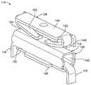
電気コネクタ200はハウジング202を具備する。ハウジング202は複数のコンタクト組立体204(図6参照)を取り囲む。複数のリセプタクル206は、ハウジング202の前部208に形成される。リセプタクル206は、ハウジング202内に配置されたコンタクト組立体204とそれぞれ整列する。リセプタクル206の数は、ハウジング202内に配置されたコンタクト組立体204の数と同じである。ハウジング202は、任意の数のコンタクト組立体204及び対応するリセプタクル206と構成可能である。各リセプタクル206は電線(図示せず)を受容するよう構成される。 The
アクチュエータ210は、ハウジング202の頂部212に配置される。アクチュエータ210は、ハウジング202の背面214に配置される。アクチュエータ210はコンタクト組立体204と係合して、接続位置218(図8参照)及び開放位置220(図9参照)間でコンタクト組立体204の可動コンタクト216(図6参照)を移動させるよう構成される。ハウジング202内に配置されたアクチュエータ210の数は、ハウジング202内に配置されたコンタクト組立体204の数と同じである。 The
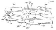
図6は、本発明の一実施形態に従って形成されたコンタクト組立体204を上から見た斜視図である。コンタクト組立体204は、基部224を有する固定コンタクト222を具備する。固定コンタクト222は1対の可動コンタクト216と一体に形成され、コンタクト組立体204を形成する。基部224は、ハウジング202(図5参照)にコンタクト組立体204を加締め実装(stake mount)するために貫通する開口226を具備する。表面実装テール部228は、基部224の前部230及び後部232から延びる。表面実装テール部228は、基板102(図1参照)に表面実装されるよう構成される。任意であるが、表面実装テール部228は、基板102にスルーホール実装されるよう構成されてもよい。 FIG. 6 is a top perspective view of a
各可動コンタクト216は、固定コンタクト222の基部224の各側面234から上方へ延びる。各可動コンタクト216は旋回部236を具備する。旋回部236は、固定コンタクト222の基部224に結合される。各可動コンタクト216の駆動端部238は、旋回部236から延びる。駆動端部238は、旋回部236から後方へ延びる。コンタクト組立体204がハウジング202内に配置されると、各可動コンタクト216の駆動端部238は、アクチュエータ210(図5参照)と係合するよう構成される。 Each
接触端部240は、各可動コンタクト216の旋回部236から前方へ延びる。接触端部240は、駆動端部238とは逆向きに延びる。各接触端部240は、電線と係合するよう構成された接触インタフェース242を具備する。特に、電線は、コンタクト組立体204が接続位置218(図8参照)にあるときに、各可動コンタクト240の接触インタフェース242の間に固定される。各接触インタフェース242は、接続位置218において電線と係合する係合タブ244を具備する。一実施形態において、電線は、係合タブ244の間に固定すなわち挟まれる。或いは、係合タブ244は電線を圧迫してもよい。 The
図7は、電気コネクタ200を下から見た斜視図である。図7は、電気コネクタ200の底部250を示す。底部250は、底部250に沿って延びる開口252を具備する。各開口252は、ハウジング202のリセプタクル206と整列する。コンタクト組立体204は各開口252内に配置される。コンタクト組立体204は、固定コンタクト222の開口226(図6参照)を通って受容される加締め部254でハウジング202に固定される。コンタクト組立体204は、リセプタクル206と整列するようにハウジング202内に配置される。各固定コンタクト222の表面実装テール部228は、ハウジング202の底部250とほぼ面一に配置される。ハウジング202が基板102に配置されると、表面実装テール部228は基板102の信号パッドと接触した状態で配置される。別の実施形態において、表面実装テール部228は、ハウジング202の底部250から延びる。このような実施形態において、表面実装テール部228は基板102にスルーホール実装される。 FIG. 7 is a perspective view of the
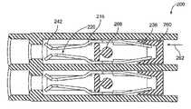
図8は、電気コネクタ200を上から見た部分断面斜視図である。コンタクト組立体204はハウジング202内に配置される。図8は、接続位置218での各コンタクト組立体204の可動コンタクト216を示す。接続位置218において、可動コンタクト216の接触インタフェース242は互いに係合する。従って、電線は、リセプタクル206に挿入されると、接触インタフェース242を押圧して離間させ、接触インタフェース242間を摺動する。接触インタフェース242は、接続位置218へ付勢されて接触インタフェース242間に電線を固定する。可動コンタクト216の係合タブ244は、その間に電線を固定すなわち挟む。 FIG. 8 is a partial cross-sectional perspective view of the
ハウジング202の後部214に、駆動楔部260が配置される。各駆動楔部260は、図5に示されるアクチュエータ210と接触状態にある。また、各駆動楔部260は、可動コンタクト216の駆動端部238と接触状態にある。アクチュエータ210は、駆動楔部260を介して可動コンタクト216と係合する。アクチュエータ210に力が印加されると、アクチュエータ210は、矢印262の向きに駆動楔部260を移動させる。駆動楔部260は、可動コンタクト216の駆動端部238と係合する1対の傾斜フランジ264を具備する。駆動楔部260が矢印262の向きに移動すると、傾斜フランジ264は、可動コンタクト216の駆動端部238を互いに向かって移動させる。 A driving
可動コンタクト216の旋回部236は、ハウジング202の旋回点266と接触状態にある。可動コンタクト216は、旋回点266の周りに回転するよう構成される。可動コンタクト216の駆動端部238が駆動楔部260によって互いに向かって強制されると、可動コンタクト216は旋回点266の周りに回転し、可動コンタクト216の接触インタフェース242を分離する。従って、可動コンタクト216は、アクチュエータ210に力を印加することにより、接続位置218から開放位置220(図9参照)まで移動される。 The turning
図9は、可動コンタクト216が開放位置220にある電気コネクタ200を上から見た部分断面斜視図である。駆動楔部260は矢印262の向きに沿って移動し、可動コンタクト216の駆動端部238を互いに向かって移動済みである。可動コンタクト216は、旋回点266の周りに回転し、可動コンタクト216の接触インタフェース242を分離済みである。従って、開放位置220において、電線は、接触インタフェース242間から取り除くことができる。 FIG. 9 is a partial cross-sectional perspective view of the
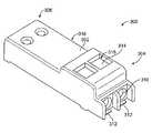
図10は、本発明の一実施形態に従って形成された別の電気コネクタ300を上から見た斜視図である。電気コネクタ300は、前端304及び後端306を有するハウジング302を具備する。ハウジング302は、コンタクト組立体308(図11及び図12に全体が図示)を保持するよう構成される。ハウジング302の前端304は、コンタクト組立体308と各々が整列するリセプタクル310を具備する。図示の実施形態は、2個のコンタクト組立体308に対応する2個のリセプタクル310を具備する。任意であるが、ハウジング302は、任意の数のリセプタクル310及び対応するコンタクト組立体308を具備してもよい。 FIG. 10 is a top perspective view of another
各コンタクト組立体308は、例えば基板102(図1参照)である基板に表面実装されるよう構成された接続端子312を具備する。或いは、接続端子312は、基板102にスルーホール実装されてもよい。また、各コンタクト組立体308は、ハウジング302の頂部318の開口316を通ってアクセス可能なアクチュエータ314を具備する。アクチュエータ314は、力320(図11参照)を受けて接続位置324(図12参照)から開放位置326(図11参照)までコンタクト組立体308の可動コンタクト322(図11及び図12参照)を移動させるよう構成される。 Each
図11は、可動コンタクト322が開放位置326にある電気コネクタ300の側断面図である。コンタクト組立体308は、可動コンタクト322及び固定コンタクト330を具備する。固定コンタクト330は、ハウジング302の前端304に配置される。固定コンタクト330は、リセプタクル310と整列する開口332を具備する。開口332は、リセプタクル310に挿入される電線333を受容するよう構成される。接続端子312は固定コンタクト330から延びる。 FIG. 11 is a side sectional view of the
可動コンタクト322はばねコンタクトとして形成される。可動コンタクト322は、基板102に実装された接続端子334を具備する。可動コンタクト322は接触インタフェース336を具備する。接触インタフェース336は、電線333を受容する開口338を具備する。接触インタフェース336はアクチュエータ314を具備する。図示の実施形態において、アクチュエータ314に力320が印加され、可動コンタクト322の接触インタフェース336を矢印340の向きに開放位置326へ移動させる。接触インタフェース336の開口338は、固定コンタクト330の開口332及びリセプタクル310と整列する。従って、コネクタ300が電線333を受容するよう構成され、電線333がコネクタ300から取外し可能である。 The
図12は、可動コンタクト322が接続位置324にある電気コネクタ300の側断面図である。接続位置324では、電線333はコネクタ300内に挿入済みである。力320(図11参照)は、アクチュエータ314から除去されている。力320が除去されると、可動コンタクト322は接続位置324へ付勢される。力320が除去されると、接触インタフェース336は矢印342の向きに移動する。接触インタフェース336は、固定コンタクト330と接触した状態で電線333を上方に押圧する、電線333上の力を生成する。固定コンタクト330の開口332により区画された上面344は、電線333と係合する。同様に、接触インタフェース336の開口338により区画された下面346は、電線333と係合する。一実施形態において、上面344及び下面346は電線333を圧迫する。電線333は、接続位置324で固定コンタクト330及び可動コンタクト322の双方との間に電気接続部を形成する。このように、固定コンタクト330及び可動コンタクト322は、電線333により電気結合される。 FIG. 12 is a side cross-sectional view of the
コネクタ300から電線333を開放するためには、電線333が取外し可能な開放位置326に可動コンタクト322が戻るようにアクチュエータ314に力320が印加される。 In order to open the
102 基板
106 信号経路
110 電気コネクタ
112 ハウジング
116 固定コンタクト
118 スルーホール実装テール部(接続端子)
120 リセプタクル
124 アクチュエータ
128 可動コンタクト
130 接続位置
132 開放位置
134 電線
142 開口
158 接触インタフェース
200 電気コネクタ
202 ハウジング
206 リセプタクル
210 アクチュエータ
216 可動コンタクト
222 固定コンタクト
228 表面実装テール部(接続端子)
242 接触インターフェース
244 係合タブ(タブ)
266 旋回点
300 電気コネクタ
302 ハウジング
310 リセプタクル
312 接続端子
314 アクチュエータ
322 可動コンタクト
330 固定コンタクト
336 接触インターフェース102
120
242
266
Claims (11)
Translated fromJapanese前記ハウジング内に配置され、信号経路に電気結合するよう構成された接続端子を有する固定コンタクトと、
前記固定コンタクトに電気結合するよう構成され、前記電線と係合する接触インタフェースを有する可動コンタクトと
を具備し、
前記接触インタフェースは、前記電線と係合する接続位置と、前記接触インタフェースが前記電線から係合解除されて前記電線が前記リセプタクルから取り外し可能となる開放位置との間を移動可能であることを特徴とする電気コネクタ。A housing having a receptacle for receiving an electrical wire;
A stationary contact having a connection terminal disposed within the housing and configured to be electrically coupled to the signal path;
A movable contact configured to be electrically coupled to the fixed contact and having a contact interface for engaging with the wire;
The contact interface is movable between a connection position that engages with the electric wire and an open position where the contact interface is disengaged from the electric wire and the electric wire can be detached from the receptacle. And electrical connector.
前記接触インタフェースが前記接続位置にあると、前記電線は前記タブの間に固定されることを特徴とする請求項1記載の電気コネクタ。The contact interface comprises a pair of tabs;
The electrical connector according to claim 1, wherein the electric wire is fixed between the tabs when the contact interface is in the connection position.
前記開口は、異なる径の電線を受容する寸法に設定されていることを特徴とする請求項1記載の電気コネクタ。The fixed contact includes an opening through which the electric wire passes and receives the electric wire,
The electrical connector according to claim 1, wherein the opening is set to a size for receiving electric wires having different diameters.
前記開口は、前記ハウジングの前記リセプタクルと整列することを特徴とする請求項1記載の電気コネクタ。The fixed contact includes an opening through which the electric wire passes and receives the electric wire,
The electrical connector of claim 1, wherein the opening is aligned with the receptacle of the housing.
Applications Claiming Priority (3)
| Application Number | Priority Date | Filing Date | Title |
|---|---|---|---|
| US13/190,025 | 2011-07-25 | ||
| US13/190,025US8550838B2 (en) | 2011-07-25 | 2011-07-25 | Electrical connector having poke-in wire contact |
| PCT/US2012/047271WO2013016105A1 (en) | 2011-07-25 | 2012-07-19 | Electrical connector having poke-in wire contact |
Publications (2)
| Publication Number | Publication Date |
|---|---|
| JP2014524132Atrue JP2014524132A (en) | 2014-09-18 |
| JP6067011B2 JP6067011B2 (en) | 2017-01-25 |
Family
ID=46601916
Family Applications (1)
| Application Number | Title | Priority Date | Filing Date |
|---|---|---|---|
| JP2014522884AActiveJP6067011B2 (en) | 2011-07-25 | 2012-07-19 | Electrical connector with poke-in wire contact |
Country Status (5)
| Country | Link |
|---|---|
| US (1) | US8550838B2 (en) |
| EP (1) | EP2737578A1 (en) |
| JP (1) | JP6067011B2 (en) |
| CN (1) | CN103703623B (en) |
| WO (1) | WO2013016105A1 (en) |
Cited By (1)
| Publication number | Priority date | Publication date | Assignee | Title |
|---|---|---|---|---|
| KR102156415B1 (en)* | 2019-07-01 | 2020-09-15 | 유선아 | Connector for multi-channel wire connection |
Families Citing this family (25)
| Publication number | Priority date | Publication date | Assignee | Title |
|---|---|---|---|---|
| DE202010000681U1 (en)* | 2010-01-07 | 2011-05-12 | Weidmüller Interface GmbH & Co. KG | Spring clamp, in particular front clamp |
| EP2792026B1 (en)* | 2011-12-14 | 2017-08-23 | Ideal Industries Inc. | Electrical connectors for use with printed circuit boards |
| US8851903B2 (en)* | 2012-07-17 | 2014-10-07 | Tyco Electronics Corporation | Connector assemblies for connector systems |
| US8764459B2 (en)* | 2012-07-17 | 2014-07-01 | Tyco Electronics Corporation | Connector assemblies for connector systems |
| USD709459S1 (en)* | 2012-11-15 | 2014-07-22 | Connector Products, Inc. | Electrical banding lead clamp |
| US8968022B2 (en)* | 2013-02-25 | 2015-03-03 | Tyco Electronics Corporation | Electrical connector having poke-in wire contact |
| KR101390960B1 (en)* | 2013-03-29 | 2014-05-02 | 몰렉스 인코포레이티드 | Poke in connector |
| TWM472352U (en)* | 2013-08-30 | 2014-02-11 | Switchlab Inc | Improved structure of wiring terminals |
| WO2015037808A1 (en)* | 2013-09-12 | 2015-03-19 | 조인셋 주식회사 | Solderable electrical connector |
| JP5604575B1 (en) | 2013-09-25 | 2014-10-08 | イリソ電子工業株式会社 | Wire conductor connection terminal |
| DE102014102845A1 (en)* | 2014-03-04 | 2015-09-10 | Phoenix Contact Gmbh & Co. Kg | Electrical terminal block |
| TWI568114B (en)* | 2014-10-03 | 2017-01-21 | Excel Cell Electronic Co Ltd | Terminal block |
| CN105680195B (en)* | 2014-11-18 | 2018-06-08 | 金笔企业股份有限公司 | Wire connecting device |
| TWM507609U (en)* | 2015-02-17 | 2015-08-21 | Switchlab Inc | Terminal block clamping structure |
| CN204558667U (en)* | 2015-04-11 | 2015-08-12 | 江门市创艺电器有限公司 | A kind of terminal connector |
| CN205039288U (en)* | 2015-08-27 | 2016-02-17 | 泰科电子(上海)有限公司 | Connector |
| TWM517439U (en)* | 2015-10-16 | 2016-02-11 | 唐虞企業股份有限公司 | Single element wire board connection terminal |
| US9692152B2 (en)* | 2015-11-13 | 2017-06-27 | Te Connectivity Corporation | Wall plate connector system |
| DE102015121638B4 (en) | 2015-12-11 | 2017-10-05 | Wago Verwaltungsgesellschaft Mbh | Conductor terminal and set of conductor terminal and operating tool |
| US9634414B1 (en)* | 2016-02-12 | 2017-04-25 | Bingshui Chen | Simple female terminal and a simple LED lamp connector for a drive board and a light board |
| US10476181B2 (en)* | 2017-01-30 | 2019-11-12 | Molex, Llc | Quick connect terminal connector |
| DE102017210348A1 (en) | 2017-06-21 | 2018-12-27 | Zf Friedrichshafen Ag | Arrangement with a printed circuit board and a terminal for electrical conductors |
| DE112018002350B4 (en) | 2017-07-07 | 2021-08-26 | Avx Corporation | WIRE-TO-WIRE CONNECTOR WITH INTEGRATED WIRE STOP |
| BE1025389B1 (en) | 2017-07-14 | 2019-02-12 | Phoenix Contact Gmbh & Co. Kg | CONNECTION DEVICE FOR CONNECTING AN ELECTRICAL LINE |
| TWI659581B (en)* | 2018-03-16 | 2019-05-11 | 進聯工業股份有限公司 | Conductive component structure of wire coupling device |
Citations (10)
| Publication number | Priority date | Publication date | Assignee | Title |
|---|---|---|---|---|
| JPS5158383U (en)* | 1974-10-31 | 1976-05-08 | ||
| JPS5526867U (en)* | 1978-08-10 | 1980-02-21 | ||
| JPS6010272U (en)* | 1983-07-01 | 1985-01-24 | 戸塚 忠男 | plug-in connector |
| JPS63182468U (en)* | 1987-05-18 | 1988-11-24 | ||
| JPH02123069U (en)* | 1989-03-17 | 1990-10-09 | ||
| JPH11162532A (en)* | 1997-08-12 | 1999-06-18 | Wago Verwaltungs Gmbh | Electric terminal |
| US5915991A (en)* | 1996-07-25 | 1999-06-29 | Claber S.P.A. | Lever terminal for electrical connectors |
| US6261120B1 (en)* | 1999-09-03 | 2001-07-17 | WEIDMüLLER INTERFACE GMBH & CO | Resilient contact for connecting electrical conductors |
| JP2003077558A (en)* | 2001-08-30 | 2003-03-14 | Sato Parts Kk | Terminal block |
| JP2011222509A (en)* | 2010-04-07 | 2011-11-04 | Virgo Verwaltungs Gmbh | Operating device for electric connection terminal |
Family Cites Families (17)
| Publication number | Priority date | Publication date | Assignee | Title |
|---|---|---|---|---|
| US3796987A (en)* | 1972-06-09 | 1974-03-12 | Amp Inc | Electrical receptacle and connector |
| US5321577A (en)* | 1992-05-08 | 1994-06-14 | The Whitaker Corporation | Protector module for telephone line pair |
| US5324213A (en) | 1993-01-21 | 1994-06-28 | The Whitaker Corporation | Ballast connector |
| IT1273099B (en) | 1994-03-31 | 1997-07-04 | Bitron A Spa | DEVICE AND METHOD FOR THE CONNECTION, BOTH MECHANICAL AND ELECTRICAL, OF A TERMINAL |
| US5525070A (en)* | 1994-04-15 | 1996-06-11 | Panduit Corp. | Positive lock insulated disconnect |
| US6244904B1 (en) | 1998-01-16 | 2001-06-12 | The Whitaker Corporation | Electrical connector for attaching conductors to speaker leads |
| FR2824960B1 (en)* | 2001-05-15 | 2003-08-15 | Entrelec | PUSH-BUTTON CONNECTION DEVICE |
| ITMI20050072U1 (en)* | 2005-03-07 | 2006-09-08 | Ilme Spa | ELECTRIC CONNECTOR ELEMENT WITH SPRING READABLE CONTACTS |
| DE102005048972B4 (en) | 2005-10-13 | 2010-08-12 | Phoenix Contact Gmbh & Co. Kg | Spring terminal with clamping spring and current bar |
| DE202006000380U1 (en) | 2006-01-11 | 2007-02-15 | Tridonicatco Connection Technology Gmbh & Co Kg | Connection element for printed circuit board, has metallic terminal with piercing clamp connection for electrical conductor |
| FR2908012B1 (en)* | 2006-10-27 | 2009-01-09 | Abb Entrelec Soc Par Actions S | ELECTRICAL APPARATUS COMPRISING AT LEAST ONE SPRING CONNECTION TERMINAL |
| US7513793B2 (en)* | 2006-12-22 | 2009-04-07 | Tyco Electronics Corporation | Surface mount poke in connector |
| US7628640B2 (en)* | 2007-12-14 | 2009-12-08 | Actuant Corporation | Electrical connector for connection to multiple conductors |
| CN101267066B (en)* | 2008-04-29 | 2010-08-11 | 卢迪 | A plug lead wiring terminal |
| DE102008039232B4 (en) | 2008-08-22 | 2019-02-28 | Phoenix Contact Gmbh & Co. Kg | Electrical connection terminal |
| IT1398659B1 (en) | 2009-06-15 | 2013-03-08 | Manca | LOW COST CLAMP FOR ELECTRICAL / ELECTRONIC APPLICATIONS ON PRINTED CIRCUIT |
| DE102010014144C5 (en) | 2010-04-07 | 2020-10-29 | Wago Verwaltungsgesellschaft Mbh | Electrical connection terminal |
- 2011
- 2011-07-25USUS13/190,025patent/US8550838B2/ennot_activeExpired - Fee Related
- 2012
- 2012-07-19JPJP2014522884Apatent/JP6067011B2/enactiveActive
- 2012-07-19WOPCT/US2012/047271patent/WO2013016105A1/enunknown
- 2012-07-19EPEP12741437.3Apatent/EP2737578A1/ennot_activeWithdrawn
- 2012-07-19CNCN201280036745.2Apatent/CN103703623B/enactiveActive
Patent Citations (10)
| Publication number | Priority date | Publication date | Assignee | Title |
|---|---|---|---|---|
| JPS5158383U (en)* | 1974-10-31 | 1976-05-08 | ||
| JPS5526867U (en)* | 1978-08-10 | 1980-02-21 | ||
| JPS6010272U (en)* | 1983-07-01 | 1985-01-24 | 戸塚 忠男 | plug-in connector |
| JPS63182468U (en)* | 1987-05-18 | 1988-11-24 | ||
| JPH02123069U (en)* | 1989-03-17 | 1990-10-09 | ||
| US5915991A (en)* | 1996-07-25 | 1999-06-29 | Claber S.P.A. | Lever terminal for electrical connectors |
| JPH11162532A (en)* | 1997-08-12 | 1999-06-18 | Wago Verwaltungs Gmbh | Electric terminal |
| US6261120B1 (en)* | 1999-09-03 | 2001-07-17 | WEIDMüLLER INTERFACE GMBH & CO | Resilient contact for connecting electrical conductors |
| JP2003077558A (en)* | 2001-08-30 | 2003-03-14 | Sato Parts Kk | Terminal block |
| JP2011222509A (en)* | 2010-04-07 | 2011-11-04 | Virgo Verwaltungs Gmbh | Operating device for electric connection terminal |
Cited By (2)
| Publication number | Priority date | Publication date | Assignee | Title |
|---|---|---|---|---|
| KR102156415B1 (en)* | 2019-07-01 | 2020-09-15 | 유선아 | Connector for multi-channel wire connection |
| WO2021002659A1 (en)* | 2019-07-01 | 2021-01-07 | 유선아 | Multi-channel wire-connecting connector |
Also Published As
| Publication number | Publication date |
|---|---|
| EP2737578A1 (en) | 2014-06-04 |
| CN103703623A (en) | 2014-04-02 |
| CN103703623B (en) | 2016-08-24 |
| US8550838B2 (en) | 2013-10-08 |
| US20130029529A1 (en) | 2013-01-31 |
| JP6067011B2 (en) | 2017-01-25 |
| WO2013016105A1 (en) | 2013-01-31 |
Similar Documents
| Publication | Publication Date | Title |
|---|---|---|
| JP6067011B2 (en) | Electrical connector with poke-in wire contact | |
| US11621510B2 (en) | Connector assembly | |
| US8708752B2 (en) | Cable assembly with lower profile interface | |
| US8684752B2 (en) | Electrical connector and electronic apparatus using the same | |
| US9935388B2 (en) | Contact-support mechanism for increased retention force | |
| NL2015465B1 (en) | Plug connector. | |
| JP2009252519A (en) | Connector for on-board mounting | |
| JP2009520329A5 (en) | ||
| US9551483B1 (en) | Multiple cable disconnect | |
| CN204597020U (en) | Electric connector combination | |
| US8137134B1 (en) | Coaxial cable connector with an insulating member with a bendable section with a pair of projections | |
| US20150318631A1 (en) | Flexible cable connector | |
| US20090137146A1 (en) | Flexible cable positioning device | |
| KR101562810B1 (en) | Flat cable connector | |
| CN2809973Y (en) | Power supply connector | |
| KR101337219B1 (en) | Connector | |
| JP4908573B2 (en) | connector | |
| CN104993270B (en) | Connector assembly | |
| JP2011228297A (en) | Usb plug socket | |
| KR101438582B1 (en) | High current electrical connector | |
| KR20210087236A (en) | Electric connecting unit | |
| KR101174845B1 (en) | Connector for connectting data cable | |
| KR101578837B1 (en) | A face contact type connecter | |
| KR20080035249A (en) | Terminal pin coupling structure of terminal block module | |
| JP2018049750A (en) | High frequency connector component and high frequency transmission cable |
Legal Events
| Date | Code | Title | Description |
|---|---|---|---|
| A621 | Written request for application examination | Free format text:JAPANESE INTERMEDIATE CODE: A621 Effective date:20150601 | |
| A977 | Report on retrieval | Free format text:JAPANESE INTERMEDIATE CODE: A971007 Effective date:20160114 | |
| A131 | Notification of reasons for refusal | Free format text:JAPANESE INTERMEDIATE CODE: A131 Effective date:20160120 | |
| A521 | Request for written amendment filed | Free format text:JAPANESE INTERMEDIATE CODE: A523 Effective date:20160419 | |
| A131 | Notification of reasons for refusal | Free format text:JAPANESE INTERMEDIATE CODE: A131 Effective date:20160921 | |
| A521 | Request for written amendment filed | Free format text:JAPANESE INTERMEDIATE CODE: A523 Effective date:20161129 | |
| TRDD | Decision of grant or rejection written | ||
| A01 | Written decision to grant a patent or to grant a registration (utility model) | Free format text:JAPANESE INTERMEDIATE CODE: A01 Effective date:20161220 | |
| A61 | First payment of annual fees (during grant procedure) | Free format text:JAPANESE INTERMEDIATE CODE: A61 Effective date:20161220 | |
| R150 | Certificate of patent or registration of utility model | Ref document number:6067011 Country of ref document:JP Free format text:JAPANESE INTERMEDIATE CODE: R150 | |
| R250 | Receipt of annual fees | Free format text:JAPANESE INTERMEDIATE CODE: R250 | |
| R250 | Receipt of annual fees | Free format text:JAPANESE INTERMEDIATE CODE: R250 | |
| R250 | Receipt of annual fees | Free format text:JAPANESE INTERMEDIATE CODE: R250 | |
| R250 | Receipt of annual fees | Free format text:JAPANESE INTERMEDIATE CODE: R250 | |
| R250 | Receipt of annual fees | Free format text:JAPANESE INTERMEDIATE CODE: R250 | |
| R250 | Receipt of annual fees | Free format text:JAPANESE INTERMEDIATE CODE: R250 | |
| S111 | Request for change of ownership or part of ownership | Free format text:JAPANESE INTERMEDIATE CODE: R313113 Free format text:JAPANESE INTERMEDIATE CODE: R313111 |