JP2014523831A - Brake system - Google Patents
Brake systemDownload PDFInfo
- Publication number
- JP2014523831A JP2014523831AJP2014517911AJP2014517911AJP2014523831AJP 2014523831 AJP2014523831 AJP 2014523831AJP 2014517911 AJP2014517911 AJP 2014517911AJP 2014517911 AJP2014517911 AJP 2014517911AJP 2014523831 AJP2014523831 AJP 2014523831A
- Authority
- JP
- Japan
- Prior art keywords
- core
- brake control
- bus
- communication
- brake
- Prior art date
- Legal status (The legal status is an assumption and is not a legal conclusion. Google has not performed a legal analysis and makes no representation as to the accuracy of the status listed.)
- Granted
Links
Images

Classifications
- B—PERFORMING OPERATIONS; TRANSPORTING
- B61—RAILWAYS
- B61C—LOCOMOTIVES; MOTOR RAILCARS
- B61C17/00—Arrangement or disposition of parts; Details or accessories not otherwise provided for; Use of control gear and control systems
- B—PERFORMING OPERATIONS; TRANSPORTING
- B60—VEHICLES IN GENERAL
- B60T—VEHICLE BRAKE CONTROL SYSTEMS OR PARTS THEREOF; BRAKE CONTROL SYSTEMS OR PARTS THEREOF, IN GENERAL; ARRANGEMENT OF BRAKING ELEMENTS ON VEHICLES IN GENERAL; PORTABLE DEVICES FOR PREVENTING UNWANTED MOVEMENT OF VEHICLES; VEHICLE MODIFICATIONS TO FACILITATE COOLING OF BRAKES
- B60T8/00—Arrangements for adjusting wheel-braking force to meet varying vehicular or ground-surface conditions, e.g. limiting or varying distribution of braking force
- B60T8/17—Using electrical or electronic regulation means to control braking
- B60T8/1701—Braking or traction control means specially adapted for particular types of vehicles
- B60T8/1705—Braking or traction control means specially adapted for particular types of vehicles for rail vehicles
- B—PERFORMING OPERATIONS; TRANSPORTING
- B60—VEHICLES IN GENERAL
- B60T—VEHICLE BRAKE CONTROL SYSTEMS OR PARTS THEREOF; BRAKE CONTROL SYSTEMS OR PARTS THEREOF, IN GENERAL; ARRANGEMENT OF BRAKING ELEMENTS ON VEHICLES IN GENERAL; PORTABLE DEVICES FOR PREVENTING UNWANTED MOVEMENT OF VEHICLES; VEHICLE MODIFICATIONS TO FACILITATE COOLING OF BRAKES
- B60T13/00—Transmitting braking action from initiating means to ultimate brake actuator with power assistance or drive; Brake systems incorporating such transmitting means, e.g. air-pressure brake systems
- B60T13/10—Transmitting braking action from initiating means to ultimate brake actuator with power assistance or drive; Brake systems incorporating such transmitting means, e.g. air-pressure brake systems with fluid assistance, drive, or release
- B60T13/66—Electrical control in fluid-pressure brake systems
- B60T13/665—Electrical control in fluid-pressure brake systems the systems being specially adapted for transferring two or more command signals, e.g. railway systems
- B—PERFORMING OPERATIONS; TRANSPORTING
- B60—VEHICLES IN GENERAL
- B60T—VEHICLE BRAKE CONTROL SYSTEMS OR PARTS THEREOF; BRAKE CONTROL SYSTEMS OR PARTS THEREOF, IN GENERAL; ARRANGEMENT OF BRAKING ELEMENTS ON VEHICLES IN GENERAL; PORTABLE DEVICES FOR PREVENTING UNWANTED MOVEMENT OF VEHICLES; VEHICLE MODIFICATIONS TO FACILITATE COOLING OF BRAKES
- B60T17/00—Component parts, details, or accessories of power brake systems not covered by groups B60T8/00, B60T13/00 or B60T15/00, or presenting other characteristic features
- B60T17/18—Safety devices; Monitoring
- B60T17/22—Devices for monitoring or checking brake systems; Signal devices
- B60T17/228—Devices for monitoring or checking brake systems; Signal devices for railway vehicles
Landscapes
- Engineering & Computer Science (AREA)
- Transportation (AREA)
- Mechanical Engineering (AREA)
- Automation & Control Theory (AREA)
- Electric Propulsion And Braking For Vehicles (AREA)
- Regulating Braking Force (AREA)
- Valves And Accessory Devices For Braking Systems (AREA)
- Braking Systems And Boosters (AREA)
Abstract
Translated fromJapaneseDescription
Translated fromJapanese本発明は、鉄道車両用ブレーキ制御装置に関する。The present invention relates to a railway vehicle brake control device.
鉄道車両の現在の標準的な通信設計は、ブレーキ制御ユニットを含む複数の装置間で列車に沿ってデータ通信可能にするCANバスを備えている。 Current standard communication designs for rail vehicles include a CAN bus that allows data communication along a train between multiple devices including a brake control unit.
CAN通信プロトコルは、数十年間の使用によって検証されている。診断ソフトウェアなどを操作するために標準的なラップトップコンピュータを使用することは現在では一般的であり、ラップトップコンピュータはCANバスに接続されてブレーキ制御ユニットと通信するために使用される。現在、RS−485、MVB及びFIPのような列車管理システム(Train Manegement System:TMS)で使用される標準インタフェースはユーザーにとって遅すぎるものと評価されており、ユーザーはイーサネットなどの高速な規格を使用することを望んでいる。 The CAN communication protocol has been validated for decades of use. It is now common to use a standard laptop computer to operate diagnostic software or the like, and the laptop computer is connected to the CAN bus and used to communicate with the brake control unit. Currently, standard interfaces used in train management systems (TMS) such as RS-485, MVB and FIP are evaluated as too slow for users, and users use high-speed standards such as Ethernet. Want to be.
この文脈におけるイーサネットは、低レベル通信システム、すなわち、物理層と最も単純なデータパケット転送を表す。ユーザーは、イーサネットの上に位置するサポートされた上位レベルプロトコル、例えば、Profinet,CIP,TCP,UDP,Webサーバ、メンテナンスを必要とする。 Ethernet in this context represents a low-level communication system, ie the physical layer and the simplest data packet transfer. Users need supported higher level protocols located on top of Ethernet, such as Profinet, CIP, TCP, UDP, Web server, maintenance.
ブレーキシステムは安全性が重要であるので、ブレーキ制御ユニットに関連する車輪滑り保護装置のようなどのモジュール上で、及び、ブレーキ制御ユニット上で実行されるどの実行可能ソフトウェアコードも、試験によりSIL2(安全度水準:Safety Integrity Level 2)に認証されることが必要である。これにより、システムに取り付けられるそれぞれの新しいモジュールは、SIL2の認証を行う必要があるという問題が生じる。しかし、これは数年の作業が必要で、且つ、多くのプロジェクトにとってあまりにも高価で時間を消費しすぎるものである。 Since the brake system is important for safety, any executable software code executed on any module, such as a wheel slip protector associated with the brake control unit, and on the brake control unit is tested to SIL2 ( It is necessary to be authenticated to the safety integrity level: Safety Integrity Level 2). This raises the problem that each new module attached to the system needs to perform SIL2 authentication. However, this requires years of work and is too expensive and time consuming for many projects.
GB2395241は、トレーラーのブレーキ電子制御装置を開示している。この電子制御装置(ECU)は、車両に関連するブレーキ関連制御パラメータを記憶するための不揮発性記憶手段と、車両の一又は複数の補助機能のための動作データを送信する個別的にプログラム可能な記憶手段とを有する。これは、エラーモードに対し制動機能を保護するように予め定義されたリストに対して一以上の入出力変数と制御アルゴリズムとをチェックするように動作可能である。このアプローチは、制御ユニット内の機能が制限されるので新しいプロトコルとインターフェイスカードをサポートするための新しいAPI(アプリケーションプログラミングインターフェイス)のためのユーザの要求を満たしていないという欠点を有する。 GB 2395241 discloses a trailer brake electronic control unit. This electronic control unit (ECU) is individually programmable to transmit non-volatile storage means for storing brake related control parameters associated with the vehicle and operational data for one or more auxiliary functions of the vehicle Storage means. This is operable to check one or more input / output variables and control algorithms against a predefined list to protect the braking function against error modes. This approach has the disadvantage that it does not meet the user's requirement for a new protocol and a new API (Application Programming Interface) to support the interface card due to limited functionality within the control unit.
従って、本発明は、より柔軟なブレーキ制御装置の構成を提供することを目的とする。 Accordingly, an object of the present invention is to provide a more flexible brake control device configuration.
本発明によれば、ブレーキ制御機能を担当する第1のコアと、通信を担当する第2のコアとを有する鉄道車両用ブレーキ制御装置が提供される。この構成は、さらに、第1のコアのブレーキ制御機能を保護するように鉄道車両上の通信バスと第2のコアとの間の通信を制御するように構成されたスイッチを備えることができ、第2のコアは、第1のコアによって許可されたときにのみ通信バスへの書き込みアクセスを行い、装置が定義された安全状態にあるか否かを第1のコアが判断することによりブレーキ制御機能を保護する。 According to the present invention, there is provided a brake control device for a railway vehicle having a first core in charge of a brake control function and a second core in charge of communication. This configuration may further comprise a switch configured to control communication between the communication bus on the rail vehicle and the second core to protect the brake control function of the first core, The second core performs write access to the communication bus only when permitted by the first core, and the first core determines whether the device is in a defined safe state, thereby controlling the brake. Protect function.
本発明による解決策では、メインの「制御」プロセッサは、従前と同様にすべての標準的なブレーキ制御アルゴリズム処理を提供するが、TMS通信は、第2の「通信」プロセッサに移動される。この通信プロセッサはSIL0に準拠し、これによりテストの必要性を低減する。 In the solution according to the invention, the main “control” processor provides all the standard brake control algorithm processing as before, but the TMS communication is moved to the second “communication” processor. This communication processor is SIL0 compliant, thereby reducing the need for testing.
また、すべての通信CPU能力は通信プロセッサによって提供され、これによりブレーキ制御アルゴリズムのための制御プロセッサの性能を向上する。 Also, all communication CPU capabilities are provided by the communication processor, thereby improving the control processor performance for the brake control algorithm.
本発明の例示的な実施形態を、図面を参照してより詳細に説明する。 Exemplary embodiments of the invention will be described in more detail with reference to the drawings.
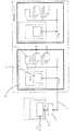
図1は、CANバス1を示す列車の広域ネットワークアーキテクチャを模式的に示す。コアCPU3を備えるブレーキ制御装置2が、バス1に接続されている。ブレーキ制御装置2は、典型的なRIO4及びRBX5モジュールなどの一以上のモジュールを備えることができ、これらモジュールはブレーキ制御装置2と直列に配置されている。ブレーキ制御装置コアCPU3は、SIL2に認証されている。RIO及びRBXモジュールもまた、SIL2規格に認証される必要があります。 FIG. 1 schematically shows a wide area network architecture of a train showing a CAN bus 1. A
標準的な診断ソフトウェアを実行するラップトップ6も、USB−CANバスドングル7を介してバス1に接続されている。この構成によりラップトップがブレーキ制御装置2と安全に通信可能となる。 A laptop 6 running standard diagnostic software is also connected to the bus 1 via a USB-CAN bus dongle 7. With this configuration, the laptop can safely communicate with the
図2は、CANバス10を示す本発明に係る列車ネットワークのアーキテクチャを模式的に示している。第1及び第2のコア12,13を備えるブレーキ制御装置11は、バス10に接続されている。ブレーキ制御装置11は、例えば典型的なRIO14及びRBX15モジュールなどの一以上のモジュールを備えることができ、これらモジュールはブレーキ制御装置11と直接に配置されている。CANバス10は、典型的には、レベル1のブレーキバスとレベル2の列車バスを有するデュアルCANバスである。 FIG. 2 schematically shows the architecture of a train network according to the present invention showing a
ブレーキ制御装置コア12は、制動機能を担当し、バスに接続されている。コア13は、通信機能を担当し、CANスイッチ16を介してバス1に接続されており、スイッチ16の動作はブレーキ制御装置コア12によって制御される。通信コア13は、CANバスから直接データを受け取ることができるが、ブレーキ制御装置コア12による明確な許可がない限りCANバスにデータを書き込むことはできない。通信コア13はWebサーバを備え、Webベースのアプリケーションが該コアにインストールされて実行されることを可能にする。通信コア13、並びに、該コア13上で実行されるどのアプリケーションやソフトウェアも、SIL2に認証される必要はない。典型的な通信コアは、ブレーキシステムへのソフトウェアアップデートやメンテナンスがある場合に該バスに書き込むのみであり、ブレーキシステムは該バスのブレーキレイヤーに沿って通信を要求する。通信コア13は、該ブレーキデータバス上のデータを監視することができ、それは該コアに記録されても上記ドライバーに返送されてもよい。余分な負荷がないので、ブレーキ制御機能から監視機能を分離すると、ブレーキコア12の性能向上をもたらすであろう。この構成は別のレベル2バスとの相互作用もまた容易にする。 The
上記SIL0プロセッサは、上記SIL2プロセッサによって有効にされた時に上記レベル1ネットワークへの書き込みアクセスを行うのみであり、上記SIL2プロセッサは、制動機能を保護するように、システムが定義された「安全状態」であるか否かを判断する。 The SIL0 processor only has write access to the level 1 network when enabled by the SIL2 processor, and the SIL2 processor is a “safe state” in which the system is defined to protect the braking function. It is determined whether or not.
上記バスには複数のセキュリティレベルが設けられており、鉄道車両ブレーキの動作に関連するなどの安全上重要なデータに用いられるレベル1での通信が最も安全である。通信コア13は、CANバスからデータを直接受信することができるが、ブレーキシステムが安全な状態であるとブレーキ制御装置コア12が判定して許可しない限り、CANバスにデータを書き込むことができない。典型的には安全状態は車両が静止しているときを含むことができるが、緊急ブレーキが適用されることを保証するか、車両が所定の時間静止していることを保証するような更なる変数を含んでもよい。 The bus is provided with a plurality of security levels, and communication at level 1 used for safety-critical data such as related to the operation of the railway vehicle brake is the safest. The
Claims (5)
Translated fromJapaneseApplications Claiming Priority (3)
| Application Number | Priority Date | Filing Date | Title |
|---|---|---|---|
| GB1111366.9 | 2011-07-04 | ||
| GB1111366.9AGB2493127C (en) | 2011-07-04 | 2011-07-04 | Braking system |
| PCT/GB2012/000570WO2013004993A1 (en) | 2011-07-04 | 2012-07-04 | Braking system |
Publications (2)
| Publication Number | Publication Date |
|---|---|
| JP2014523831Atrue JP2014523831A (en) | 2014-09-18 |
| JP6170915B2 JP6170915B2 (en) | 2017-07-26 |
Family
ID=44512038
Family Applications (1)
| Application Number | Title | Priority Date | Filing Date |
|---|---|---|---|
| JP2014517911AActiveJP6170915B2 (en) | 2011-07-04 | 2012-07-04 | Brake system |
Country Status (8)
| Country | Link |
|---|---|
| US (1) | US9434391B2 (en) |
| EP (1) | EP2892771B1 (en) |
| JP (1) | JP6170915B2 (en) |
| KR (1) | KR101960400B1 (en) |
| CN (1) | CN103702878B (en) |
| BR (1) | BR112014000844B1 (en) |
| GB (1) | GB2493127C (en) |
| WO (1) | WO2013004993A1 (en) |
Families Citing this family (9)
| Publication number | Priority date | Publication date | Assignee | Title |
|---|---|---|---|---|
| GB2529478B (en)* | 2014-08-22 | 2020-11-04 | Knorr Bremse Rail Systems Uk Ltd | Self testing process for a railway brake system |
| CN104374586B (en)* | 2014-11-25 | 2017-10-31 | 中车青岛四方机车车辆股份有限公司 | high-speed train braking system simulation test platform and test method |
| CN105383475A (en)* | 2015-11-25 | 2016-03-09 | 南京浦镇海泰制动设备有限公司 | Brake control device for railway vehicle |
| EP3179674B1 (en) | 2015-12-10 | 2019-04-03 | KNORR-BREMSE Systeme für Schienenfahrzeuge GmbH | Configurable gateway apparatus and method for an integrated brake control system in a railway vehicle |
| CN106218623B (en)* | 2016-08-03 | 2018-10-12 | 张惠 | A kind of electric locomotive train tube pressure control module |
| DE102017208840C5 (en)* | 2017-05-24 | 2022-12-08 | Knorr-Bremse Systeme für Schienenfahrzeuge GmbH | Braking device and method for performing emergency braking of a rail vehicle |
| EP3461703B2 (en) | 2017-09-27 | 2024-08-14 | KNORR-BREMSE Systeme für Schienenfahrzeuge GmbH | Integrated brake control system and method for rail vehicles |
| CN110704359A (en)* | 2019-08-14 | 2020-01-17 | 北京中电华大电子设计有限责任公司 | High-safety low-power-consumption communication method of dual-core chip |
| CN110775099B (en)* | 2019-11-07 | 2022-01-25 | 交控科技股份有限公司 | Integration method of communication system in train |
Citations (8)
| Publication number | Priority date | Publication date | Assignee | Title |
|---|---|---|---|---|
| JP2002165312A (en)* | 2000-11-20 | 2002-06-07 | Nippon Signal Co Ltd:The | Renewal system for vehicle-mounted data and renewal method for the vehicle-mounted data |
| JP2004284376A (en)* | 2003-03-19 | 2004-10-14 | Denso Corp | Air bag system |
| JP2006527688A (en)* | 2003-06-18 | 2006-12-07 | クノール−ブレームス レール システムス (ユーケー) リミテッド | Digital data bus |
| JP2008242719A (en)* | 2007-03-27 | 2008-10-09 | Kyosan Electric Mfg Co Ltd | Control system, communication method, operation terminal, control device, and program |
| JP2009538024A (en)* | 2006-05-18 | 2009-10-29 | エヌエックスピー ビー ヴィ | Gateway for data bus system |
| US20100094489A1 (en)* | 2008-10-10 | 2010-04-15 | Robert Lyn Moffitt | System and method for reducing a penalty period for a distributed power train |
| JP2011503563A (en)* | 2007-11-02 | 2011-01-27 | コンチネンタル・テベス・アーゲー・ウント・コンパニー・オーハーゲー | Digital map validation |
| JP2012527142A (en)* | 2009-05-11 | 2012-11-01 | コンチネンタル・テベス・アーゲー・ウント・コンパニー・オーハーゲー | Two-way ad hoc-network wireless communication controller |
Family Cites Families (8)
| Publication number | Priority date | Publication date | Assignee | Title |
|---|---|---|---|---|
| US6334654B1 (en)* | 1996-09-13 | 2002-01-01 | New York Air Brake Corporation | Integrated train electrical and pneumatic brakes |
| GB2395241B (en)* | 2002-11-12 | 2004-12-29 | Knorr Bremse Systeme | Electronic control apparatus for a vehicle |
| JP2004341814A (en)* | 2003-05-15 | 2004-12-02 | Toshiba Corp | SIL (Safety-Integrity Levels) monitor and design support device using SIL model |
| CN100334512C (en)* | 2004-12-31 | 2007-08-29 | 武汉正远铁路电气有限公司 | Traction control system for stationary reconnection locomotive |
| US8788135B2 (en)* | 2006-03-20 | 2014-07-22 | General Electric Company | System, method, and computer software code for providing real time optimization of a mission plan for a powered system |
| CN101426676B (en)* | 2006-04-18 | 2013-04-24 | 通用电气公司 | System and method for determining brake application level of a remote locomotive notifying a train |
| US7850127B2 (en)* | 2008-03-11 | 2010-12-14 | Ansaldo Sts Usa, Inc. | Cab signal receiver demodulator employing redundant, diverse field programmable gate arrays |
| CN101497343B (en)* | 2009-01-22 | 2011-02-02 | 北京全路通信信号研究设计院 | Operation control method and operation control system of combined train |
- 2011
- 2011-07-04GBGB1111366.9Apatent/GB2493127C/enactiveActive
- 2012
- 2012-07-04CNCN201280036531.5Apatent/CN103702878B/enactiveActive
- 2012-07-04BRBR112014000844-2Apatent/BR112014000844B1/enactiveIP Right Grant
- 2012-07-04EPEP12735163.3Apatent/EP2892771B1/enactiveActive
- 2012-07-04JPJP2014517911Apatent/JP6170915B2/enactiveActive
- 2012-07-04USUS14/130,973patent/US9434391B2/enactiveActive
- 2012-07-04WOPCT/GB2012/000570patent/WO2013004993A1/enactiveApplication Filing
- 2012-07-04KRKR1020147002781Apatent/KR101960400B1/enactiveActive
Patent Citations (8)
| Publication number | Priority date | Publication date | Assignee | Title |
|---|---|---|---|---|
| JP2002165312A (en)* | 2000-11-20 | 2002-06-07 | Nippon Signal Co Ltd:The | Renewal system for vehicle-mounted data and renewal method for the vehicle-mounted data |
| JP2004284376A (en)* | 2003-03-19 | 2004-10-14 | Denso Corp | Air bag system |
| JP2006527688A (en)* | 2003-06-18 | 2006-12-07 | クノール−ブレームス レール システムス (ユーケー) リミテッド | Digital data bus |
| JP2009538024A (en)* | 2006-05-18 | 2009-10-29 | エヌエックスピー ビー ヴィ | Gateway for data bus system |
| JP2008242719A (en)* | 2007-03-27 | 2008-10-09 | Kyosan Electric Mfg Co Ltd | Control system, communication method, operation terminal, control device, and program |
| JP2011503563A (en)* | 2007-11-02 | 2011-01-27 | コンチネンタル・テベス・アーゲー・ウント・コンパニー・オーハーゲー | Digital map validation |
| US20100094489A1 (en)* | 2008-10-10 | 2010-04-15 | Robert Lyn Moffitt | System and method for reducing a penalty period for a distributed power train |
| JP2012527142A (en)* | 2009-05-11 | 2012-11-01 | コンチネンタル・テベス・アーゲー・ウント・コンパニー・オーハーゲー | Two-way ad hoc-network wireless communication controller |
Also Published As
| Publication number | Publication date |
|---|---|
| CN103702878B (en) | 2016-05-04 |
| BR112014000844B1 (en) | 2020-11-17 |
| GB2493127A (en) | 2013-01-30 |
| GB2493127B (en) | 2018-01-17 |
| WO2013004993A1 (en) | 2013-01-10 |
| JP6170915B2 (en) | 2017-07-26 |
| KR20140054016A (en) | 2014-05-08 |
| CN103702878A (en) | 2014-04-02 |
| KR101960400B1 (en) | 2019-03-20 |
| GB201111366D0 (en) | 2011-08-17 |
| EP2892771A1 (en) | 2015-07-15 |
| EP2892771B1 (en) | 2016-12-14 |
| US9434391B2 (en) | 2016-09-06 |
| BR112014000844A2 (en) | 2017-04-18 |
| US20140257604A1 (en) | 2014-09-11 |
| GB2493127C (en) | 2020-08-05 |
Similar Documents
| Publication | Publication Date | Title |
|---|---|---|
| JP6170915B2 (en) | Brake system | |
| JP6329075B2 (en) | Communication system for vehicle | |
| JP6626811B2 (en) | Fraud detection electronic control unit, in-vehicle network system and fraud detection method | |
| JP7231559B2 (en) | Anomaly detection electronic control unit, in-vehicle network system and anomaly detection method | |
| US10268557B2 (en) | Network monitoring device, network system, and computer program product | |
| JP7006461B2 (en) | Electronic control device and electronic control system | |
| US20190246294A1 (en) | Apparatus and method for controlling vehicle based on redundant architecture | |
| US20190012483A1 (en) | Electronic Control Units for Vehicles | |
| AU2018356262B2 (en) | Safety system for a building-related passenger transportation system | |
| JP2017524587A (en) | Method and apparatus for monitoring a vehicle system that performs at least a semi-automated driving function | |
| US20220300612A1 (en) | Security processing device | |
| US20230267205A1 (en) | Mitigation of a manipulation of software of a vehicle | |
| US20230267204A1 (en) | Mitigating a vehicle software manipulation | |
| CN117492946A (en) | Ways to control access to various applications in the vehicle | |
| JP6874102B2 (en) | Fraud detection electronic control unit, in-vehicle network system and fraud detection method | |
| JP2023144496A (en) | System, vehicle and method | |
| US20230267213A1 (en) | Mitigation of a manipulation of software of a vehicle | |
| JP6547533B2 (en) | Motor drive | |
| CN108011972A (en) | Data processing method and system | |
| JP2023116355A (en) | In-vehicle device | |
| JP6410232B2 (en) | Communications system | |
| CN117728970A (en) | Technique for mitigating on-board network maneuvers |
Legal Events
| Date | Code | Title | Description |
|---|---|---|---|
| A621 | Written request for application examination | Free format text:JAPANESE INTERMEDIATE CODE: A621 Effective date:20150702 | |
| A977 | Report on retrieval | Free format text:JAPANESE INTERMEDIATE CODE: A971007 Effective date:20160516 | |
| A131 | Notification of reasons for refusal | Free format text:JAPANESE INTERMEDIATE CODE: A131 Effective date:20160621 | |
| A601 | Written request for extension of time | Free format text:JAPANESE INTERMEDIATE CODE: A601 Effective date:20160920 | |
| A521 | Request for written amendment filed | Free format text:JAPANESE INTERMEDIATE CODE: A523 Effective date:20161004 | |
| A601 | Written request for extension of time | Free format text:JAPANESE INTERMEDIATE CODE: A601 Effective date:20161110 | |
| A521 | Request for written amendment filed | Free format text:JAPANESE INTERMEDIATE CODE: A523 Effective date:20161110 | |
| TRDD | Decision of grant or rejection written | ||
| A01 | Written decision to grant a patent or to grant a registration (utility model) | Free format text:JAPANESE INTERMEDIATE CODE: A01 Effective date:20170606 | |
| A61 | First payment of annual fees (during grant procedure) | Free format text:JAPANESE INTERMEDIATE CODE: A61 Effective date:20170703 | |
| R150 | Certificate of patent or registration of utility model | Ref document number:6170915 Country of ref document:JP Free format text:JAPANESE INTERMEDIATE CODE: R150 | |
| R250 | Receipt of annual fees | Free format text:JAPANESE INTERMEDIATE CODE: R250 | |
| R250 | Receipt of annual fees | Free format text:JAPANESE INTERMEDIATE CODE: R250 | |
| R250 | Receipt of annual fees | Free format text:JAPANESE INTERMEDIATE CODE: R250 | |
| R250 | Receipt of annual fees | Free format text:JAPANESE INTERMEDIATE CODE: R250 | |
| R250 | Receipt of annual fees | Free format text:JAPANESE INTERMEDIATE CODE: R250 | |
| R250 | Receipt of annual fees | Free format text:JAPANESE INTERMEDIATE CODE: R250 |