JP2014519269A - Integrated building network - Google Patents
Integrated building networkDownload PDFInfo
- Publication number
- JP2014519269A JP2014519269AJP2014511434AJP2014511434AJP2014519269AJP 2014519269 AJP2014519269 AJP 2014519269AJP 2014511434 AJP2014511434 AJP 2014511434AJP 2014511434 AJP2014511434 AJP 2014511434AJP 2014519269 AJP2014519269 AJP 2014519269A
- Authority
- JP
- Japan
- Prior art keywords
- remote
- socket
- communication
- network
- wiring
- Prior art date
- Legal status (The legal status is an assumption and is not a legal conclusion. Google has not performed a legal analysis and makes no representation as to the accuracy of the status listed.)
- Granted
Links
- 238000004891communicationMethods0.000claimsabstractdescription129
- 238000009826distributionMethods0.000claimsdescription78
- 230000007246mechanismEffects0.000claimsdescription53
- 239000000853adhesiveSubstances0.000claimsdescription44
- 230000001070adhesive effectEffects0.000claimsdescription43
- RYGMFSIKBFXOCR-UHFFFAOYSA-NCopperChemical compound[Cu]RYGMFSIKBFXOCR-UHFFFAOYSA-N0.000claimsdescription21
- 239000010949copperSubstances0.000claimsdescription18
- 229910052802copperInorganic materials0.000claimsdescription18
- 230000005540biological transmissionEffects0.000claimsdescription16
- 230000005855radiationEffects0.000abstractdescription7
- 239000000835fiberSubstances0.000description132
- 239000013307optical fiberSubstances0.000description65
- 239000010410layerSubstances0.000description27
- 230000003287optical effectEffects0.000description22
- 238000003860storageMethods0.000description20
- 239000012790adhesive layerSubstances0.000description19
- 238000010586diagramMethods0.000description16
- 230000000630rising effectEffects0.000description16
- 230000008878couplingEffects0.000description14
- 238000010168coupling processMethods0.000description14
- 238000005859coupling reactionMethods0.000description14
- 239000004020conductorSubstances0.000description12
- 239000000463materialSubstances0.000description11
- 229910052751metalInorganic materials0.000description11
- 239000000758substrateSubstances0.000description11
- 238000009434installationMethods0.000description10
- 239000002184metalSubstances0.000description9
- 238000000034methodMethods0.000description9
- 230000008569processEffects0.000description8
- 238000005520cutting processMethods0.000description7
- 238000013461designMethods0.000description7
- 238000000465mouldingMethods0.000description7
- 238000011900installation processMethods0.000description6
- 238000010276constructionMethods0.000description5
- 238000009413insulationMethods0.000description5
- 229920003023plasticPolymers0.000description5
- 239000004033plasticSubstances0.000description5
- 238000012546transferMethods0.000description5
- 239000004593EpoxySubstances0.000description4
- 239000004820Pressure-sensitive adhesiveSubstances0.000description4
- 239000004566building materialSubstances0.000description4
- 238000012986modificationMethods0.000description4
- 230000004048modificationEffects0.000description4
- 239000003522acrylic cementSubstances0.000description3
- 230000001413cellular effectEffects0.000description3
- 238000006243chemical reactionMethods0.000description3
- 239000002131composite materialSubstances0.000description3
- 230000006835compressionEffects0.000description3
- 238000007906compressionMethods0.000description3
- 230000009977dual effectEffects0.000description3
- 239000007769metal materialSubstances0.000description3
- 239000007787solidSubstances0.000description3
- 101001074557Arabidopsis thaliana Aquaporin PIP1-3Proteins0.000description2
- 229920006347ElastollanPolymers0.000description2
- 241000196324EmbryophytaSpecies0.000description2
- 238000005452bendingMethods0.000description2
- 230000008901benefitEffects0.000description2
- 230000003750conditioning effectEffects0.000description2
- 238000005336crackingMethods0.000description2
- 238000005516engineering processMethods0.000description2
- 230000004927fusionEffects0.000description2
- 150000002500ionsChemical class0.000description2
- 238000012423maintenanceMethods0.000description2
- 238000003032molecular dockingMethods0.000description2
- 239000002861polymer materialSubstances0.000description2
- 229920000098polyolefinPolymers0.000description2
- 229920003225polyurethane elastomerPolymers0.000description2
- 239000004800polyvinyl chlorideSubstances0.000description2
- 230000003014reinforcing effectEffects0.000description2
- 238000000926separation methodMethods0.000description2
- 238000012360testing methodMethods0.000description2
- 239000002023woodSubstances0.000description2
- RNFJDJUURJAICM-UHFFFAOYSA-N2,2,4,4,6,6-hexaphenoxy-1,3,5-triaza-2$l^{5},4$l^{5},6$l^{5}-triphosphacyclohexa-1,3,5-trieneChemical compoundN=1P(OC=2C=CC=CC=2)(OC=2C=CC=CC=2)=NP(OC=2C=CC=CC=2)(OC=2C=CC=CC=2)=NP=1(OC=1C=CC=CC=1)OC1=CC=CC=C1RNFJDJUURJAICM-UHFFFAOYSA-N0.000description1
- 230000009471actionEffects0.000description1
- 230000003213activating effectEffects0.000description1
- 239000000654additiveSubstances0.000description1
- 239000002390adhesive tapeSubstances0.000description1
- 229910052782aluminiumInorganic materials0.000description1
- XAGFODPZIPBFFR-UHFFFAOYSA-NaluminiumChemical compound[Al]XAGFODPZIPBFFR-UHFFFAOYSA-N0.000description1
- 230000003321amplificationEffects0.000description1
- 238000013459approachMethods0.000description1
- 230000000712assemblyEffects0.000description1
- 238000000429assemblyMethods0.000description1
- 239000000969carrierSubstances0.000description1
- 230000008859changeEffects0.000description1
- 239000003795chemical substances by applicationSubstances0.000description1
- 238000007796conventional methodMethods0.000description1
- 239000003989dielectric materialSubstances0.000description1
- 238000006073displacement reactionMethods0.000description1
- 238000001125extrusionMethods0.000description1
- 239000003063flame retardantSubstances0.000description1
- 239000011888foilSubstances0.000description1
- 238000003780insertionMethods0.000description1
- 230000037431insertionEffects0.000description1
- 230000003278mimic effectEffects0.000description1
- 239000002991molded plasticSubstances0.000description1
- 238000003199nucleic acid amplification methodMethods0.000description1
- 238000005457optimizationMethods0.000description1
- 230000005693optoelectronicsEffects0.000description1
- 238000005192partitionMethods0.000description1
- 230000000149penetrating effectEffects0.000description1
- 230000035515penetrationEffects0.000description1
- 230000002093peripheral effectEffects0.000description1
- 239000013308plastic optical fiberSubstances0.000description1
- 229920002635polyurethanePolymers0.000description1
- 239000004814polyurethaneSubstances0.000description1
- 238000002360preparation methodMethods0.000description1
- 230000000644propagated effectEffects0.000description1
- 238000010079rubber tappingMethods0.000description1
- 239000004065semiconductorSubstances0.000description1
- 229910001220stainless steelInorganic materials0.000description1
- 239000010935stainless steelSubstances0.000description1
- 238000004804windingMethods0.000description1
Images


Classifications
- H—ELECTRICITY
- H01—ELECTRIC ELEMENTS
- H01Q—ANTENNAS, i.e. RADIO AERIALS
- H01Q1/00—Details of, or arrangements associated with, antennas
- H01Q1/007—Details of, or arrangements associated with, antennas specially adapted for indoor communication
- H—ELECTRICITY
- H01—ELECTRIC ELEMENTS
- H01Q—ANTENNAS, i.e. RADIO AERIALS
- H01Q21/00—Antenna arrays or systems
- H01Q21/28—Combinations of substantially independent non-interacting antenna units or systems
- H—ELECTRICITY
- H01—ELECTRIC ELEMENTS
- H01Q—ANTENNAS, i.e. RADIO AERIALS
- H01Q9/00—Electrically-short antennas having dimensions not more than twice the operating wavelength and consisting of conductive active radiating elements
- H01Q9/04—Resonant antennas
- H01Q9/16—Resonant antennas with feed intermediate between the extremities of the antenna, e.g. centre-fed dipole
- H01Q9/26—Resonant antennas with feed intermediate between the extremities of the antenna, e.g. centre-fed dipole with folded element or elements, the folded parts being spaced apart a small fraction of operating wavelength
- H01Q9/27—Spiral antennas
Landscapes
- Installation Of Indoor Wiring (AREA)
- Mobile Radio Communication Systems (AREA)
- Small-Scale Networks (AREA)
- Telephonic Communication Services (AREA)
- Near-Field Transmission Systems (AREA)
- Cable Transmission Systems, Equalization Of Radio And Reduction Of Echo (AREA)
- Light Guides In General And Applications Therefor (AREA)
Abstract
Translated fromJapaneseDescription
Translated fromJapanese本発明は、統合型建物内ネットワークを目的とする。より具体的には、本明細書に記載されるネットワークは、有線建物内遠隔通信、並びに建物内無線(IBW)ネットワークを提供するための複合型ネットワークソリューションである。 The present invention is directed to an integrated building network. More specifically, the network described herein is a complex network solution for providing wired in-building telecommunications as well as in-building wireless (IBW) networks.
多世帯住宅(MDU)は世界中に数百万とあり、世界人口の約3分の1がそれらに居住している。1つのMDUに多数の居住者が集中しているため、サービスプロバイダにとっては、これらの構造へのファイバ・トゥー・ザ・エックス(「FTTX」)配備は、一世帯住宅への配備よりもコスト効果が高い。既存のMDUをFTTXネットワークに接続することは、困難である場合が多い。難点としては、建物へのアクセスの獲得、立ち上がりクローゼット内の限られた配線スペース、並びにケーブルルーティング及び管理のためのスペースが挙げられる。具体的には、既存構造内のFTTX配備では、中央クローゼット又は階段吹き抜けから各住戸へ、壁若しくは床の中、又は天井の上にケーブルを配線することが難しい。 Multi-family homes (MDUs) are in the millions around the world, and about one-third of the world's population lives in them. For service providers, fiber-to-the-X (“FTTX”) deployment in these structures is more cost-effective than single-family home deployment due to the large number of residents concentrated in one MDU Is expensive. Connecting existing MDUs to an FTTX network is often difficult. Difficulties include gaining access to the building, limited wiring space in the rising closet, and space for cable routing and management. Specifically, in an FTTX deployment within an existing structure, it is difficult to route cables from the central closet or stairwell to each dwelling unit, in the wall or floor, or on the ceiling.
従来、サービスプロバイダは、エンクロージャ(ファイバ配線ターミナル(FDT)としても既知)をMDUのそれぞれの階又はいくつかの階ごとに設置している。FDTは、建物の立ち上がりケーブルを、1つの階のそれぞれの住戸につながる水平ドロップケーブルに接続する。ドロップケーブルは、ある住戸の居住者がサービスを要請した場合のみFDT内で立ち上がりケーブルにスプライスされるか他の方法で接続される。これらのサービスの設置は、エンクロージャに何度も入ることが必要なので、その階の他の居住者のセキュリティ及びサービスの混乱のリスクがある。また、このタイプの接続は、高価な融着スプライス機と高度な技術を有する労働力の使用が必要なので、このプロセスは、サービスプロバイダの資本金及び運転経費も増加させる。個々のドロップケーブルのルーティングとスプライスには多大な時間がかかり、1日に1人の技術者が作動させることができる受信契約者の数が増えず、サービスプロバイダの収益を低減する場合がある。別の方法として、サービスプロバイダは、MDU内の各住戸からの家庭内配線を直接、建物天井のファイバ配線ハブ(FDH)まで全延長を延ばして設置することにより、単一の延長されたドロップケーブルで水平ケーブルと立ち上がりケーブルの両方を網羅する。このアプローチは、複数のドロップケーブルのそれぞれを管理、保護、及び隠すために1つの経路を最初に設置する必要性を含んだいくつかの難点を生む。この経路は、しばしば、非常に大きい(例えば、2インチ(5.1cm)〜4インチ(10.2cm)〜6インチ(15.2cm))木材、複合材料、又はプラスチックで作製された既製のクラウンモールディングを含む。これらの経路の多くでは、時間経過と共に混み合い、秩序が乱れ、ファイバの屈曲及び過度のリエントリによりサービスの混乱をきたすリスクが増す。 Traditionally, service providers install an enclosure (also known as a fiber wiring terminal (FDT)) on each floor or several floors of the MDU. The FDT connects the building's rising cable to a horizontal drop cable connected to each dwelling unit on one floor. The drop cable is spliced or otherwise connected to the rising cable within the FDT only when a resident of a given unit requests service. Because the installation of these services requires multiple entry into the enclosure, there is a risk of security and service disruption for other residents on that floor. This process also increases the service provider's capital and operating costs because this type of connection requires the use of expensive fusion splice machines and highly skilled labor. The routing and splicing of individual drop cables is time consuming and does not increase the number of subscribers that can be operated by one technician per day, which can reduce service provider revenue. Alternatively, the service provider can install a single extended drop cable by installing in-home wiring from each dwelling unit in the MDU directly to the fiber wiring hub (FDH) on the building ceiling. Covers both horizontal and rising cables. This approach creates several difficulties, including the need to first install one path to manage, protect, and hide each of the multiple drop cables. This path is often very large (eg, 2 inches (5.1 cm) to 4 inches (10.2 cm) to 6 inches (15.2 cm)) off-the-shelf crowns made of wood, composites, or plastics. Including molding. Many of these paths become crowded over time, out of order, increasing the risk of disruption of service due to fiber bending and excessive reentry.
ますます増加する顧客に望ましい帯域幅を提供するために、より良好な無線通信カバレッジが必要とされている。したがって、従来の大型の「マクロ」セルサイトを新たに配備することに加えて、「ミクロ」セルサイト(オフィスビルディング、学校、病院、及び集合住宅などの構造物内にあるサイト)の数を増加する必要がある。建物内無線(IBW)分散アンテナシステム(DAS)を利用して、建物及び関連建造物内の無線カバレージが向上される。通常のDASは、計画的に配置されたアンテナ又は漏洩同軸ケーブル(漏洩coax)を建物の至る所で使用して、300MHz〜6GHzの周波数範囲にある高周波(RF)信号に適応する。従来のRF技術としては、TDMA、CDMA、WCDMA(登録商標)、GSM(登録商標)、UMTS、PCS/セルラー、iDEN、WiFi、及びその他多数が挙げられる。 In order to provide the desired bandwidth to an increasing number of customers, better wireless communication coverage is needed. Therefore, in addition to newly deploying large traditional “macro” cell sites, increase the number of “micro” cell sites (sites in structures such as office buildings, schools, hospitals, and housing complexes) There is a need to. Intra-building wireless (IBW) distributed antenna systems (DAS) are utilized to improve radio coverage in buildings and related structures. A typical DAS uses a deliberately arranged antenna or leaky coaxial cable (leakage coax) throughout the building to accommodate radio frequency (RF) signals in the frequency range of 300 MHz to 6 GHz. Conventional RF technologies include TDMA, CDMA, WCDMA®, GSM®, UMTS, PCS / Cellular, iDEN, WiFi, and many others.
米国外では、通信事業者は、いくつかの国で法律により、建物内部での無線カバレッジを拡大することを求められる。米国内では、帯域幅要求及び安全に対する懸念により、特に世界的に、現在の4G以上のアーキテクチャに移行するにつれて、IBWアプリケーションが推進されるであろう。 Outside the United States, carriers are required by law in some countries to expand radio coverage inside buildings. Within the United States, bandwidth requirements and security concerns will drive IBW applications, especially globally, as they move to current 4G and higher architectures.
建物内部で無線通信を分配するためのネットワークアーキテクチャには、既知のものが多数ある。これらのアーキテクチャには、受動、活性、及びハイブリッドシステムの選択が含まれる。アクティブアーキテクチャは、概して光ファイバケーブルを通して、RF信号を再構成し、かつ信号を送信/受信する遠隔電子装置に通される操作RF信号を含む。受動アーキテクチャは、通常は離散アンテナ又はパンクチャーシールド「漏洩同軸ケーブル」ネットワークを通して信号を放射及び受信するための構成部分を含む。ハイブリッドアーキテクチャは、アクティブ信号の分配点に光学的に通されるネイティブRF信号を含み、これは、次いで多重の送信/受信アンテナを終端とする複数の同軸ケーブルに供給する。具体的な例には、アナログ/増幅RF、RoF(光ファイバ無線)、ピコセル及びフェムトセルへのファイババックホール、及びリモートユニットから水平配線の残り(例えばフロア内)への広範な受動的同軸分配を伴う、RoF垂直又は立ち上がり分配が挙げられる。これらの従来のアーキテクチャは、電子的複雑性及び費用、容易にサービスを追加できないこと、全てのサービスの組合せを支持できないこと、距離制限、又は煩雑な設置要件に関する制限を有する可能性がある。 There are many known network architectures for distributing wireless communications within buildings. These architectures include the choice of passive, active and hybrid systems. The active architecture generally includes an operational RF signal that is passed through a fiber optic cable to a remote electronic device that reconstructs the RF signal and transmits / receives the signal. Passive architectures typically include components for radiating and receiving signals through a discrete antenna or puncture shielded “leaky coaxial cable” network. The hybrid architecture includes a native RF signal that is optically passed to the active signal distribution point, which then feeds multiple coaxial cables terminated with multiple transmit / receive antennas. Specific examples include analog / amplified RF, RoF (fiber optic radio), fiber backhaul to picocells and femtocells, and extensive passive coaxial distribution from the remote unit to the rest of the horizontal wiring (eg in the floor) RoF vertical or rising distribution with These conventional architectures may have limitations regarding electronic complexity and cost, inability to easily add services, inability to support all service combinations, distance limitations, or complex installation requirements.
IBW用途の従来の配線としては、RFS社(www.rfsworld.com)から入手可能なRADIAFLEX(商標)配線、水平配線用の標準的な1/2インチ(1.3cm)の同軸ケーブル、立ち上がり配線用の7/8インチ(2.2cm)の同軸ケーブル、並びに、立ち上がり及び水平分配用の標準的な光ファイバ配線が挙げられる。 Conventional wiring for IBW applications includes RADAFLEX ™ wiring available from RFS (www.rfsworld.com), standard 1/2 inch (1.3 cm) coaxial cable for horizontal wiring, and rising wiring. 7/8 inch (2.2 cm) coaxial cable, and standard fiber optic wiring for rise and horizontal distribution.
異なる無線ネットワークアーキテクチャ、特に古い建物及び構造物内にIBW配線を提供するには、物理的及び審美的な難題が存在する。それらの難点としては、建物へのアクセスの獲得、立ち上がりクローゼット内の限られた配線スペース、並びにケーブルルーティング及び管理のためのスペースが挙げられる。 There are physical and aesthetic challenges in providing IBW wiring in different wireless network architectures, particularly in old buildings and structures. These difficulties include gaining access to the building, limited wiring space in the rising closet, and space for cable routing and management.
本発明の例示的な態様により、建物内での通信のための統合型ネットワークが説明される。統合型ネットワークは、有線建物内遠隔通信、並びに建物内無線ネットワークを提供するための、複合型ネットワークソリューションである。 In accordance with exemplary aspects of the present invention, an integrated network for communication within a building is described. An integrated network is a complex network solution for providing wired in-building telecommunications as well as in-building wireless networks.
統合型ネットワークは、無線通信用の通信線に連結される分散アンテナシステム(DAS)ハブと、有線通信及び無線通信用の通信線を通すための水平配線と、遠隔ソケットと、を含む。水平配線は、遠隔通信信号を建物内部に伝えるために、有線及び無線通信線を通すダクトである。遠隔ソケットは、無線通信線を遠隔電子ユニットと接続する。加えて、1つ以上のアンテナは、アナログRF電気的放射を、遠隔ソケットから、接着剤で裏当てされた同軸配線を通して、室内環境へ伝えるために、遠隔ソケットにも連結することができる。例示的な態様では、水平配線は、少なくとも1つのコンジット部と、接着剤の裏当て部を有するフランジと、を有する接着剤で裏当てされたダクトであり、有線及び無線通信線は、ダクト構造のコンジット部を通ってボア内に配置される。 The integrated network includes a distributed antenna system (DAS) hub connected to a communication line for wireless communication, horizontal wiring for passing a communication line for wired communication and wireless communication, and a remote socket. The horizontal wiring is a duct through which wired and wireless communication lines are passed in order to transmit a remote communication signal to the inside of the building. The remote socket connects the wireless communication line with the remote electronic unit. In addition, one or more antennas can also be coupled to the remote socket to conduct analog RF electrical radiation from the remote socket through the adhesive-backed coaxial wiring to the indoor environment. In an exemplary aspect, the horizontal wiring is an adhesive-backed duct having at least one conduit portion and a flange having an adhesive backing portion, and the wired and wireless communication lines have a duct structure. Is placed in the bore through the conduit section.
建物内の場所で、有線通信用の通信線及び無線通信用の通信線を更に分配するために、DASハブと遠隔ソケットとの間に配置される分岐点を更に含むことができる。 A branch point disposed between the DAS hub and the remote socket may be further included to further distribute the communication line for wired communication and the communication line for wireless communication at a location in the building.
統合型ネットワークの遠隔ソケットは、遠隔電子ユニットを受容するためのソケットを含み、このソケットは、遠隔電子ユニット内に収納される遠隔電子装置に接続するために、複数の媒体を収納するように構成される。ソケットは、遠隔電子ユニットインターフェースと嵌合するように構成されたソケットインターフェースを含み、ソケット及び遠隔電子ユニットのうち少なくとも1つは、複数の媒体を同時に接続するように構成された作動機構を更に含む。 The integrated network remote socket includes a socket for receiving a remote electronic unit, the socket configured to receive a plurality of media for connection to a remote electronic device housed within the remote electronic unit. Is done. The socket includes a socket interface configured to mate with the remote electronic unit interface, and at least one of the socket and the remote electronic unit further includes an actuation mechanism configured to connect a plurality of media simultaneously. .
代替的な実施形態では、例示的な建物内無線ネットワークが開示される。例示的な無線ネットワークは、無線通信のための通信線に連結される分散アンテナシステムハブと、無線通信線を通すための水平配線と、遠隔ソケットと、を含む。水平配線は、建物内部で無線通信線を通すダクトである。遠隔ソケットは、無線通信線を遠隔電子ユニットと接続する。加えて、1つ以上のアンテナは、遠隔ソケットから、接着剤で裏当てされた同軸配線を通して、室内環境へ、アナログRF電気的放射を搬送するために、遠隔無線ソケットにも連結することができる。 In an alternative embodiment, an exemplary in-building wireless network is disclosed. An exemplary wireless network includes a distributed antenna system hub coupled to a communication line for wireless communication, horizontal wiring for passing the wireless communication line, and a remote socket. Horizontal wiring is a duct through which a wireless communication line passes inside a building. The remote socket connects the wireless communication line with the remote electronic unit. In addition, one or more antennas can also be coupled to the remote radio socket to carry analog RF electrical radiation from the remote socket through the adhesive-backed coaxial wiring to the indoor environment. .
本発明の上記の概要は、本発明の図示された各実施形態又は全ての実施の記述を意図するものではない。下記の図及び発明を実施するための形態によって、これらの実施形態を更に詳細に例示する。 The above summary of the present invention is not intended to describe each illustrated embodiment or every implementation of the present invention. These embodiments are illustrated in further detail by the following figures and modes for carrying out the invention.
本発明を、添付図面を参照して更に詳しく記述する。 The invention will be described in more detail with reference to the accompanying drawings.
本発明には様々な改変及び代替的形態が可能であり、その具体例を一例として図面に示すとともに詳細に記述する。しかしながらその目的とするところは、本発明を記述された特定の実施形態に限定することにはないことが理解されるべきである。逆に、添付の請求の範囲によって定義された発明の範囲内に包含される、あらゆる改造、均等物、及び代替物を含むことを意図する。 While the invention is susceptible to various modifications and alternative forms, specific examples thereof are shown by way of example in the drawings and will herein be described in detail. It should be understood, however, that the intention is not to limit the invention to the particular embodiments described. On the contrary, the intention is to cover all modifications, equivalents, and alternatives falling within the scope of the invention as defined by the appended claims.
以下の発明を実施するための形態においては、本明細書の一部を構成する添付の図面を参照し、本発明を実施することができる特定の実施形態を例として示す。この点に関して、「上」、「下」、「前」、「後」、「先」、「前方」、「背向」その他、などの方向用語は、記載される図の配向に関して用いられる。本発明の実施形態の構成部分は多くの異なる配向に位置付けることができるので、方向に関する用語は、説明を目的として使われるものであって、決して限定するものではない。他の実施形態が利用されてもよく、また構造的又は論理的な変更を、本発明の範囲から逸脱することなく行ってもよいことを理解すべきである。以下の詳細な説明は、したがって、限定的な意味で解釈されるべきではなく、また、本発明の範囲は、添付の特許請求の範囲によって定義される。 In the following detailed description, reference is made to the accompanying drawings that form a part hereof, and in which is shown by way of illustration specific embodiments in which the invention may be practiced. In this regard, directional terms such as “top”, “bottom”, “front”, “back”, “front”, “front”, “backward”, etc. are used with respect to the orientation of the described figures. Since components of embodiments of the present invention can be positioned in many different orientations, the terminology is used for purposes of explanation and is in no way limiting. It should be understood that other embodiments may be utilized and structural or logical changes may be made without departing from the scope of the present invention. The following detailed description is, therefore, not to be taken in a limiting sense, and the scope of the present invention is defined by the appended claims.
本発明は、統合型建物内ネットワークを目的とする。より具体的には、本明細書に記載されるネットワークは、有線建物内遠隔通信、並びに建物内無線(IBW)ネットワークを提供するための複合型ネットワークソリューションである。本明細書に記載されるネットワークは、ダクトに入れられた水平配線によって相互接続する様々なノードを含むモジュラーシステムである。 The present invention is directed to an integrated building network. More specifically, the network described herein is a complex network solution for providing wired in-building telecommunications as well as in-building wireless (IBW) networks. The network described herein is a modular system that includes various nodes that are interconnected by horizontal wiring encased in a duct.
水平配線ソリューションは、データ及び通信転送のために建物内無線ネットワーク及びFTTXネットワークの両方にサービスを提供する、同軸(coax)ケーブル、ツイストペア線銅線などの通信銅線、光ファイバ、及び/又は配電配線のための標準無線周波数(RF)信号経路を含むことができる信号経路を提供する。水平配線は、既存の壁又は天井の表面上への設置を、穴を開けること、壁を通してケーブルを送り込むこと、及び/又は他の方法で既存の構造物を損傷する必要を低減して行えるように、接着剤で裏当てすることができる。水平配線は、より良好な審美性のために影響が少ない形状を有し、一方で、依然として、RF/セルラー、ツイストペア線銅線、及び光ファイバの複数チャネルを供給する、分配された柔軟性のあるネットワーク設計、及び所与の室内環境に対する最適化を可能にするデータトラフィックを提供する。 Horizontal wiring solutions provide communication copper, fiber, and / or power distribution, such as coax cable, twisted pair copper, to serve both in-building wireless networks and FTTX networks for data and communication transfer A signal path is provided that can include a standard radio frequency (RF) signal path for wiring. Horizontal wiring can be installed on the surface of an existing wall or ceiling, reducing the need to drill holes, route cables through the wall, and / or otherwise damage existing structures. It can be backed with an adhesive. The horizontal wiring has a low impact shape for better aesthetics, while still providing distributed flexibility to provide multiple channels of RF / cellular, twisted pair copper, and fiber. It provides data traffic that allows certain network designs and optimization for a given indoor environment.
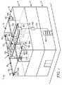
図1は、その内部に設置される例示的な統合型ネットワークソリューションを有する例示的な多世帯住宅(MDU)1を示す。MDUは、建物内のそれぞれの階5で、中央の廊下7の両側に2つの住戸が位置して、4つの住戸10を含む。 FIG. 1 illustrates an exemplary multi-family residence (MDU) 1 having an exemplary integrated network solution installed therein. The MDU includes four dwelling
加入者岐線ケーブル(図示せず)は、従来の通信ネットワークから、建物(例えば、MDU 1)への及びそれからの有線通信線をもたらし、かつ同軸フィードは、近くにある無線タワー又は基地局から建物内へ、RF又は無線信号をもたらす。すべての引込み線(例えば、光ファイバ、同軸ケーブル、及び従来の銅線)は、地下室又はMDUに最も近い装置内にある、主分配施設又は主分配ラック200内に供給される。主分配ラック200は、建物に入ってくる信号を、室内の統合型ネットワークのために、外部のネットワークから集中型のアクティブ機器へ編成する。主電源及び非常用電源も、主分配ラックを通して分配することができる。更に、統合型ネットワークを支持し、かつプラントの外側から建物の中へ、及び建物内ネットワークの残りへ信号を通すケーブルを管理するファイバ及び電力ケーブル管理は、主分配施設内に位置することができる。主分配ラック200は、1つ以上の装置シャーシ並びに遠隔通信ケーブル管理モジュールを保持することができる。主分配施設内でラック上に位置する可能性がある例示的な装置としては、例えば、複数のRF信号源、RF調整ドロワ、1次分散アンテナシステム(DAS)ハブ、配電装置、及びDAS遠隔管理装置を挙げることができる。例示的な遠隔通信ケーブル管理モジュールとしては、例えば、ファイバ分配ハブ、ファイバ配線ターミナル、又はパッチパネルを挙げることができる。 A subscriber line cable (not shown) provides a wired communication line from and to a building (eg, MDU 1) from a conventional communication network, and a coaxial feed from a nearby radio tower or base station to the building Into the RF or radio signal. All lead wires (eg, optical fiber, coaxial cable, and conventional copper wire) are fed into a main distribution facility or
立ち上がりケーブル又は幹線ケーブル120が、主分配施設内の主分配ラック200から、MDU 1のそれぞれの階5に位置するエリアジャンクションボックス400まで延びる。エリアジャンクションボックスは、それぞれの階で、水平のファイバの延長及び所望により電力配線を集める能力を提供する。エリアジャンクションボックスにおいて、基幹配線は、光ファイバ又は他の通信ケーブル及び/又は電力ケーブルを含む数多くの配線構造物へと出てゆき、これらは上に記載される水平配線130によって、MDU内に分配される。これらの配線構造物は、本明細書に記載される、接着剤で裏当てされた配線ダクト設計を利用する。入口点ボックス500は、電力及び通信ケーブルを住戸内で使用するように水平配線130から分割するために、それぞれの住戸において中央の廊下内に位置する。 A rising cable or
遠隔ソケット600は、廊下7内で、水平配線130上に配置することができ、廊下で、強い無線信号を確実にするために、分散アンテナ800に接続することができる。 The
ケーブルは、住戸10内の第2の入口点ボックス500’(図2)を通って、住戸に入る。住戸の入口点ボックスは、図1の廊下7に示す入口点ボックス500と類似とすることができ、又は住戸では第2の入口点ボックスでは一般的により少ない通信線又はケーブルを取り扱うので、より小さくすることができる。入口点ボックス500’を通して住戸に入るケーブルは、遠隔ソケット600、更にそれぞれの住戸の内側にある通信装置910への接続、又はファイバジャンパー930(図2)によって通信装置の部分を接続することができる壁レセプタクル920を供給する。例示的な通信装置としては、一世帯住戸光ネットワークターミナル(SFU ONT)、デスクトップONT、又は類似のデバイス(例えば、Alcatel−Lucentから入手可能な7342 Indoor Optical Terminal又はMotorola ONT1120GE Desktop ONT)を挙げることができる。 The cable enters the dwelling unit through the second
遠隔ソケットを供給する光ファイバ及び電力ケーブルは、無線ダクト150内に配置することができる。無線ダクト150は、MDU内の壁又は天井に、接着剤により載置することができる。無線ダクトは、ダクト内の1つ以上の光ファイバ及び少なくとも2つの電力線を通すことになる。例示的な無線ダクトは、米国特許公報第2009−0324188号及び同第2010−0243096号に記載され、その全体が参照により本明細書に組み込まれる。 The optical fiber and power cable that supply the remote socket can be placed in the
一態様では、遠隔ソケット600は、遠隔中継器/無線電子装置又は稼動中の電子装置と構造化された配線システムとの間の共通インターフェースを容易にするための無線アクセスポイント(WAP)を含むことができる。遠隔ソケットは、光学RFを電気信号に変換する遠隔無線電子装置などの遠隔電子ユニット内にプラグ接続するのを容易にし、IBW分配システム用のアナログRF電気信号の放射のために、これを分散アンテナ800に更に分配する。 In one aspect, the
分散アンテナ800は、短い長さの同軸ケーブル160によって遠隔ソケット600に接続することができる。アンテナは、容認できる信号レベルで包括的なカバレージを達成するように、建物の周りから離間される。一実施形態では、同軸ケーブル160は、同軸ケーブルのMDU内の壁又は天井への取り付けを容易にするために、接着剤の裏当て層を含むことができる。例示的な接着剤で裏当てされた同軸ケーブルは、その全体が参照により本明細書に組み込まれる、米国特許出願第13/454569号に記載される。 The distributed
光ドロップファイバは、廊下の入口点ボックス500から、壁コンセント920又は通信装置910の一部などの住戸10内のアンカーポイントまで、遠隔通信ダクト140を介して、通すことができる。好ましい態様では、遠隔通信ダクト140は、住戸の壁、天井、カーペット下、床、又は内部角に沿って目立たない様式で配置される薄型のダクトとすることができ、これにより、住戸の審美性は最小限しか影響を受けない。例示的な薄型のダクトは、米国特許公報第2011−0030832号及び同第2010−0243096号に記載され、その全体が参照により本明細書に組み込まれる。 The optical drop fiber can pass through the
図2は、MDU 1(図1参照)などの例示的な建物の住戸10内に設置される、統合型建物内ネットワークの部分の概略図を示す。システムは、ファイバトゥーザホーム(FTTH)システム及び無線通信システムなどの有線遠隔通信部分を含む。 FIG. 2 shows a schematic diagram of a portion of an integrated in-building network that is installed in a
FTTHシステムのサブシステムである、例示的なドロップアクセスシステム900は、MDU 1(図1参照)などの例示的な建物の住戸10内に設置される最終的なドロップ又は遠隔通信ダクト140を含む。ドロップアクセスシステム900は、MDUなどの建物内に設置されるものとして本明細書に記載されるが、本明細書に与えられる技術分野の当業者には明らかであるように、これは、音声及びデータ信号のために光ファイバ伝送システムを提供するのが有利である場合がある一世帯住宅又は類似の住居、オフィスビルディング、病院、又は他の建物にも利用されてもよいことに留意されたい。 An exemplary
ドロップアクセスシステム900は、MDUなどの建物の水平配線/サービス線との接続のための1つ以上の通信線(図2には図示さないドロップファイバ又はドロップ電線などの)を含む、遠隔通信ダクト140を含む。電線、同軸/マイクロ同軸ケーブル、ツイストペア線ケーブル、イーサネット(登録商標)ケーブル、又はこれらの組み合わせが、データ、ビデオ、及び/又は電話信号の伝送のために使用されてもよいが、通信線は、好ましくは、1つ又は2つの光ファイバからなってもよい。一態様では、通信線は、900μm緩衝ファイバ、500μm緩衝ファイバ、250μmファイバ、又は他の標準寸法の通信繊維などの、分離している(まとまっていない)ドロップファイバからなってもよい。光ファイバは、単一モード又は複数モードとすることができる。例示の複数モードファイバは、50μmコア寸法、62.5μmコア寸法、80μmコア寸法、又は異なる標準コア寸法を有することができる。別の代替の態様では、ドロップファイバは、従来のプラスチック光ファイバからなってもよい。最終的なドロップファイバは、米国特許第7,369,738号に記載されるような、光ファイバコネクタで現場終端処理することができる。SC−APC、SC−UPC、又はLCなどの他の光ファイバコネクタを利用することができる。 Drop
加えて、本明細書に記載した例示的な態様は、しばしば光ファイバ線へのアクセスに特定のものであるが、本明細書に与えられる技術分野の当業者は、電線ドロップ及び/又はハイブリッド組み合わせドロップにも適応するようにドロップアクセスシステム900を構成することができることを理解するであろう。例えば、電線ドロップは、RG6シールド及び/又は非シールドケーブルなどの、従来のCat 5/Cat 6配線又は従来の同軸配線からなってもよい。 In addition, the exemplary aspects described herein are often specific to accessing fiber optic lines, but those skilled in the art given herein will be able to provide wire drop and / or hybrid combinations. It will be appreciated that the
ドロップアクセスシステム900は、MDU内に提供される水平配線にアクセスを提供するために、住戸内の1つ以上のアクセス地点に位置する1つ以上の入口点ユニット500’を含む。好ましい態様では、入口点ユニットは、アクセス地点に位置する薄型のアクセスベースユニット(遠隔通信ダクト140及び無線ダクト150の少なくとも一部分の上方又は上に載置可能な)からなる。 The
MDU内に提供される例示的なドロップアクセスシステム及び水平配線の設置方法は、その全体が参照により本明細書に組み込まれる、米国特許公報第2009−0324188号に記載される。 An exemplary drop access system and horizontal wiring installation method provided within an MDU is described in US Patent Publication No. 2009-0324188, which is incorporated herein by reference in its entirety.
一態様では、遠隔通信ダクト140内のドロップ線(例えば、ファイバ)は、MDUの廊下に配置されるドロップアクセスボックス500(図1を参照)内に位置する標準カップリングを介して、サービスプロバイダ線に連結することができる。終端処理ドロップファイバなどのドロップ線、又は他の通信線を、入口点ボックス500’から住戸内の第2のアンカーポイントへ、好ましい態様では、遠隔通信ダクト140を介して壁コンセント920へ通すことができる。好ましい態様では、遠隔通信ダクト140は、住戸の壁、天井、カーペット下、床、又は内部角に沿って目立たない様式で配置され、これにより住戸の審美性は最小限しか影響を受けない。遠隔通信ダクト140は、その全体が参照により本明細書に組み込まれる米国特許公報第2011−0030190号に記載されるように、接着剤で裏当てされたダクトとして構成することができる。 In one aspect, the drop line (eg, fiber) in the
上述するように、ドロップアクセスシステム900は、ドロップ線を受容し、かつ住戸内に位置する遠隔通信装置910(すなわち、光学ネットワークターミナル(ONT))との接続を提供するために、入口点から離れて第2のアンカーポイントを含む。好ましい態様では、第2のアンカーポイントは、ドロップ線(例えば、ドロップファイバ又はドロップワイヤ)を受容するように構成され、かつONTとの接続を提供する、一家族ユニット光学ネットワークターミナル(SFU ONT)、デスクトップONT、又は類似のデバイス(例えば、Alcatel−Lucentから入手可能な7342 Indoor Optical Terminal又はMotorola ONT1120GE Desktop ONT)などの、マルチメディア壁コンセント920からなる。 As described above, the
例示的な態様によると、壁コンセント920は、住戸の至る所に全体にネットワークケーブルを分配するように構成される。それ自体、壁コンセント920は、例えば、同軸接地ブロック若しくはスプリッター、RJ11アダプタ(カップラー又はジャックなど)、RJ45アダプタ(カップラー又はジャックなど)、又はファイバSC/APCアダプタ/コネクタを使用して、複数のマルチメディア接続を提供するように構成することができる。図2に示すように、ファイバジャンパー930は、レセプタクルをONTに接続することができる。 According to exemplary aspects, the
遠隔ソケットを供給する光ファイバ及び電力ケーブルは、入口点ボックス500’から遠隔ソケット600まで無線ダクト150を通して経路決定することができる。無線ダクト150は、MDU内の壁又は天井に、接着剤により載置することができる。無線ダクトは、ダクト内の1つ以上の光ファイバ及び少なくとも2つの電力線を通すことになる。 The optical fiber and power cable supplying the remote socket can be routed through the
遠隔ソケット600は、稼動中の電子装置と構築された配線システムとの間の共通インターフェースを容易にするために、遠隔中継器/無線電子装置を含むことができる。遠隔ソケットは、光学RFを電気信号に変換する遠隔無線電子装置にプラグ接続するのを容易にし、更にIBW分配システム用のアナログRF電気信号の放射のためにこれを分散アンテナ800に分配する。 The
分散アンテナ800は、短い長さの同軸ケーブル160によって遠隔ソケット600に接続することができる。一実施形態では、同軸ケーブル160は、同軸ケーブルのMDU内の壁又は天井への取り付けを容易にするために、接着剤の裏当て層を含むことができる。 The distributed
図3は、複数層の建物に設置される統合型建物内ネットワークの無線ネットワークの部分を示す。この概略図の建物は、3層、すなわち3つの階5を含む。 FIG. 3 shows the wireless network portion of an integrated in-building network installed in a multi-tiered building. The building in this schematic diagram includes three layers, ie three
従来の通信ネットワークからの、有線通信線(例えば、銅線又は光ファイバ)用の加入者岐線ケーブル110及び同軸加入者岐線ケーブル112は、近くにある無線タワー又は基地局からRF又は無線信号を建物内にもたらす。すべての引込み線(例えば、光ファイバ、同軸、そして従来の銅線)は、通常、建物の1回又は地下に位置する主分配施設又は装置クローゼット内の主分配ラック200内に供給される。主分配ラック200は、建物に入ってくる信号を、室内の統合型ネットワークのために、外部のネットワークから集中型のアクティブ機器へ編成する。主電源114及び非常用電源も、主分配ラックを通して分配することができる。更に、有線ネットワーク及び無線ネットワークの両方の統合型ネットワークをサポートし、かつ外側のプラントから建物内へ、及び残りの建物内ネットワーク上への両方の信号を通すケーブルを管理するファイバ及び送電線管理は、主分配施設内に位置することができる。主分配ラック200は、1つ以上の装置シャーシ並びに遠隔通信ケーブル管理モジュールを保持することができる。
水平配線130aは、図3に示すように、主分配ラックと同じ階の位置などの建物内の主分配ラック200に近い位置に無線及び有線信号を分配する。水平配線130aは、複数の光ファイバ及び2つ以上の電力線を含むことになる。所望により、水平配線130aは、1つ以上の通信銅線も含むことができる。水平配線130aは、水平配線の長さに沿って順次離間して1つ以上の遠隔ソケット600a、600a’へ、そして最終的に同軸ケーブル160a、160a’によってそれぞれの遠隔ソケットに取り付けられる分散アンテナ800a、800a’へ無線信号を直接的に通す。水平配線によって通される光ファイバ及び電力ケーブルの数は、いくつかの要因によることになる。第1の要因は、統合型ネットワークの特定の無線部分に対する、水平配線の分岐上でサポートされる遠隔ソケットの数である。別の要因は、統合型ネットワークのFTTx部分をサポートする光ファイバで供給される有線通信リンクの数である。更に別の要因は、ネットワークのそれぞれの部分のそれぞれのノード(すなわち、いくつの遠隔ソケットに加えていくつのFTTxノード)をサポートするために、いくつのファイバが要求されるかである。それぞれの遠隔ソケットは、1つから2つの光ファイバ入力、1つから2つの光ファイバ出力、及び/又は2つの電力線を利用する場合がある。FTTxノードは、一般的には最高4つの光ファイバによってサービスを受ける。同軸ケーブルは、単一の同軸ケーブル160a、160a’、160b’又はアンテナ800c’にデュアルリンクを提供するための2本の同軸ケーブル160c’のいずれかを含むことができる。 As shown in FIG. 3, the
それぞれの遠隔ソケットは、遠隔ソケット600a〜600c用に示されるように、1つのアンテナを支持することができ、又は遠隔ソケット600a’、600b’用に示すように、多重のアンテナ800a’、800b’をサポートすることができる。2つ以上のアンテナが遠隔ソケットに取り付けられるとき、アンテナ800b’は、遠隔ソケット600b’用に示されるように、同軸ケーブル160b’によってスター状で取り付けることができ、又はアンテナ800a’は、遠隔ソケット600a’から延在する同軸ケーブル160a’などの同軸ケーブルに沿って順次離間することができる。 Each remote socket can support one antenna, as shown for
立ち上がりケーブル又は幹線ケーブル120は、主分配ラック200から、特定のネットワーク構成のための必要に応じて、建物のそれぞれの階、又は交互の階にある装置クロージャ内に位置する局所設備ラック300へ、延ばすことができる。図3は、概略図で表わされる、建物の2階及び3階のそれぞれにある局所設備ラックを示す。例示的な態様では、立ち上がりケーブル120は、複数の光ファイバ及び/又は複数の通信銅線を含むことになる。DC電力を、局所設備ラック300を介して、水平配線内に追加することができ、これは以下に更に詳細に記載される。代替的には、電力は、主分配ラックからの立ち上がりケーブルを通して、遠隔電子装置(すなわち、遠隔ソケット)に通すことができる。 The rising or
図3に示すように建物1の2階では、遠隔ソケット600bの部分は、水平配線130bによって供給される。遠隔ソケットの第2のグループ分けは、エリアジャンクションボックス400を通過する水平配線130b’によって供給することができる。2次的な水平配線139は、エリアジャンクションボックス400から遠隔ソケット600b’、600b’’までケーブルを経路設定する。 As shown in FIG. 3, on the second floor of the
図4は、主分配ラック200の略図を示す。主分配ラック200は、建物に入ってくる信号を、室内の統合型ネットワークのために、外部のネットワークから集中型のアクティブ機器へ編成する。主分配ラック200は、1つ以上の装置シャーシ並びに遠隔通信ケーブル管理モジュールを保持することができる。主分配ラックは、無線分配システム及び有線FTTH MDUシステムの両方をサポートするために使用される、アクティブな1次及び2次ネットワーク装置の共通の構成を提供するモジュール方式とすることができる。例示的な態様では、主分配ラックは、建物の主分配施設内の複数ラックを利用することができる。 FIG. 4 shows a schematic diagram of the
図4に示す例示的な態様では、主分配ラック200は、2つのサブラック201a、201bを利用する。サブラックは、従来の19インチ装置ラック、21インチ装置ラック又は任意の他の均等物のラックシステムとして構成することができる。第1のサブラック201aは、2つから4つのRF信号源210、RF調整ドロワ215、及び1次分散アンテナシステム(DAS)ハブ220を保持するように構成することができる。 In the exemplary embodiment shown in FIG. 4, the
それぞれのサービスプロバイダから入ってくるRF信号は、主分配ラック内に位置するRF信号源200によって、例示的な統合型ネットワーク内へと導かれる。RF信号源は、多くの場合、所与のサービスプロバイダによって所有されている。信号源は、双方向増幅器、基地局、又は他のタイプのRF信号源装置構成とすることができる。これらの信号源は、所有しているサービスプロバイダが認可された無線周波数でRF信号を送信及び受容する。例示的なRF信号源としては、Ericsson(Stockholm,SE)から入手可能なRBS 2000 Series Indoor Base Stations、Nokia Siemens Networks(Espoo,FI)から入手可能なFlexi Multiradio 10 Base Station、又はCommscope,Inc.(Hickory,NC)から入手可能なNode−A Repeaterが挙げられる。 Incoming RF signals from each service provider are directed into an exemplary integrated network by an
RF調整ドロワ215は、RF信号源のためのインターフェース点として作用する。RF調整ドロワは、(カップラー、減衰、その他)RF信号源から入ってくるRF信号を編成し、かつ調節して、アクティブなDAS装置内への入力のために多帯域信号を組み合わせる。例示的なRF調整ドロワ又はユニットは、Bravo Tech,Inc(Cypress,CA)からのPOI Series製品を含む。 The
1次DASハブ300は、RF調整ドロワからの信号を取り、RF信号を光学的な信号に変換し、かつ光学的な信号を、信号を遠隔無線ソケットへ通す信号モードの光ファイバへと入力し、そこで、これらは周囲へのブロードキャストのために分散アンテナに伝達されるRF信号へと変換して戻される。例示的な1次DASハブは、Zinwave(Cambridge,UK)から入手可能なZinwave’s 3000 Distributed Antenna System Primary Hub、又はCommscope,Inc.(Hickory,NC)から入手可能なION(商標)−B Master Unit Subrackである。それぞれの1次DASハブは、設定した数の遠隔ユニットを提供することができる。遠隔ユニットは、主分配ラック若しくは局所設備ラックのいずれか、又は遠隔ソケットに位置することができる2次DASハブとすることができる。1次DASハブによってサービスを受けることができるよりも多くの遠隔ソケットが有る場合、2次DASハブは、システムの設備能力を拡張するために1次DASハブにリンクすることができる。 The
第2のサブラック201bは、ファイバ分配ハブ240、ファイバ配線ターミナル245、2次DASハブ250、配電モジュール255、無停電電源260、及びDAS遠隔管理システム265を保持するように構成することができる。 The second subrack 201b can be configured to hold a
ファイバ分配ハブ240は、光ファイバ加入者岐線ケーブルと建物内ファイバネットワークとの間に、高密度のファイバ接続点を提供することができる。一方で、ファイバ配線ターミナル245は、統合型システムのサブセクションの所与の階に、水平配線内の光ファイバとファイバ分配ハブから来る光ファイバを交差接続、相互接続、及び管理することができる。例示的なファイバ分配ハブ及びターミナルは、3M Company(St.Paul,MN)から入手可能な、3M(商標)8400 Series Fiber Distribution Unitsから選択することができる。 The
前に述べたように、2次DASハブ200を、数が増加した遠隔ユニットにサービスを提供するように、ネットワークに追加することができる。特に、サブラック201b内の2次DASハブ200は、遠隔ユニット(例えば、遠隔ソケット)を、建物の主要階にサービスを提供することができる。例示的な2次DASハブは、Zinwave(Cambridge,UK)から入手可能な、最高8つの遠隔ソケットを供給することができる、Zinwave’s 3000 Distributed Antenna System Secondary Hub、又はCommscope,Inc.(Hickory,NC)から入手可能なION(商標)−B Master Unit Subrackである。 As previously mentioned, a
配電モジュール255は、水平配線を通して、エリアジャンクションボックス及び/又は遠隔ソケット内の遠隔電子装置に電力を提供するための48VDC配電モジュールとすることができる。無停電電源260は、停電の場合に、基本レベルでその機能性を維持するか、又は通常の装置の運転停止を許容するかのいずれかのように必要不可欠な電子装置に電力を提供する。例示的な無停電電源は、Tripp Lite(Chicago,IL)又はAmerican Power Conversion Corporation(W.Kingston,RI)から入手可能である。
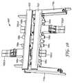
立ち上がりケーブル又は幹線ケーブル120は、主分配ラックから建物のそれぞれの階の分岐点へのRF及び光ファイバ通信信号を主分配施設内に通す。図39は、統合型ネットワーク内で使用するための例示的な幹線ケーブル又は立ち上がりケーブル120を示す。立ち上がりケーブル120は、それを通して提供される中央ボア122を有する主本体121を有するダクトの形態をとることができる。この態様では、中央ボア122は、その内部に有線システムのためのRF通信線及び光ファイバ通信線の形態の複数の光ファイバリボン199、並びに少なくとも2つの電力線195を収容するように寸法設定される。この例では、中央ボアは、それぞれのリボンの中に8つの光ファイバを有する8つの光ファイバリボン199を収容するように寸法設定される。当然のことながら、用途により、より多い又はより少ない数の光ファイバリボン及び/又はそれぞれのリボン内に光ファイバを利用することができる。光ファイバは、RoF又はFTTH信号を通すために、最適化することができる。例えば、光ファイバは、単一モード光ファイバを備えることができる。いくつかの用途では、複数モードファイバも利用することができる。 The riser cable or
別の代替の態様では、接着剤で裏当てされた立ち上がりケーブルは、CAT5e、CAT6線などの、ツイストペア線上のイーサネット(登録商標)として構成される1つ以上の通信チャネルを更に含むことができる。別の代替案では、電力は、同軸線の1つ以上の導電性コア上で送信することができる。 In another alternative aspect, the adhesive-backed riser cable can further include one or more communication channels configured as Ethernet over twisted pair wires, such as CAT5e, CAT6 wires, and the like. In another alternative, power can be transmitted on one or more conductive cores of the coaxial line.
立ち上がりケーブル120は、水平の配線に、壁、又は床、天井、若しくはモールディングなどの載置面に設置されるか、または載置されるように、ダクトの支持を提供するために、フランジ又は類似の平坦部分を含む。好ましい態様では、フランジは、概して平坦面の形状をともなう背面又は底面を有するフランジ部分124a、124bを含む。好ましい態様において、接着剤層127は、フランジ部分の底面126の全体又は少なくとも一部に配置される、エポキシ、転写接着剤、アクリル接着剤、感圧接着剤、両面テープ、又は除去可能な接着剤のような接着剤を含む。例示的な接着剤材料の更なる考察が、以下に提供される。 The
上に記載される立ち上がりケーブル120は、電力線及び通信線を主分配ラックから、建物のそれぞれの階に位置するエリアジャンクションボックス400又は局所設備ラックなどの集中型分岐点に供給する。代替的には、立ち上がりケーブル120は、例えば、オフィスビルディング、病院又は教育施設などの建物の他のタイプの分岐点に電力線及び通信線を供給する。次いで、信号を、遠隔ソケット又はボックスの点への水平配線の延長によって広めることができる。 The
代替的な態様では、図39に示すような立ち上がりケーブル120は、水平ケーブルの延長に使用することができ、起こる場合があるような、多数の光ファイバが必要になる。 In an alternative embodiment, the rising
図5は、局所設備ラック300の略図を示す。局所設備ラックは、存在点(POP)ラック又はキャビネットである。局所設備ラックは、階の寸法(すなわち、面積)に応じて、MDUの1階おきに、又は各階に、適当な装置室又は他の適切な場所に局所化することができる。局所設備ラックは、従来の19インチ装置ラック、21インチ装置ラック、又は任意の他の均等物のラックシステムとして構成することができる。立ち上がりケーブルは、主分配ラックから信号入力を提供する。それぞれの局所設備ラックは、ファイバ配線ターミナル345、2次DASハブ350、及び配電モジュール365を含むことができる。ファイバ配線ターミナル345は、建物のそれぞれの階で、立ち上がりケーブルからの光ファイバを、水平配線内に含まれる光ファイバと相互接続し、並びに光ファイバを、立ち上がりケーブルから2次DASハブ350に接続する。加えて、ファイバ配線ターミナル345は、2次DASハブからのファイバを接続することになり、これらを統合型ネットワークの無線部分を支持する光ファイバに接続する。配電モジュール365は、エリアジャンクションボックス内の遠隔電子装置及び/又は遠隔ソケットに水平配線を通して電力を提供するための48VDC配電モジュールとすることができる。 FIG. 5 shows a schematic diagram of a
エリアジャンクションボックス400は、局所設備ラックから来る水平配線と遠隔ソケット並びにFTTHネットワークに供給するために延びる2次水平配線との間の分岐点を提供することができる。例えば、それぞれのエリアジャンクションボックスは、最大12のFTTHドロップ及びそれぞれが少なくとも2つの光ファイバ接続を必要とする最大8つの遠隔ソケットに対するファイバ支持に適応することができる。加えて、それぞれのエリアジャンクションボックスは、最大8つの遠隔ソケットに供給する必要がある電力線の支持を提供することになる。例示的なエリアジャンクションボックスとしては、3M Company(St.Paul,MN)から入手可能な、3M(商標)VKA 2/GF光ファイバ分配ボックスを挙げることができる。 The
上述するように、水平配線130は、有線及び無線通信の両方のプラットフォームのために、MDUのそれぞれの階に沿って電力及び通信線を供給することができる。水平配線は、局所分配点又は分岐点と無線ネットワーク内の遠隔電子装置との間に、及び局所分配点と個々の住戸又は建物内のサービス供給点との間に信号経路を提供する。本発明の好ましい態様では、水平配線は、接着剤で裏当てされた構造の配線ダクトとして提供することができる。しかしながら、水平配線の他の形態も本明細書に記載される統合型ネットワーク内で利用することができる。 As described above, the
図6Aは、統合型ネットワーク内で使用するための例示的な水平配線130の形態を示す。水平配線130は、それを通過する中央ボア132及びダクトのフランジ構造物134内に形成される追加的なボア133a、133bを有する主本体131を有するダクトの形態とすることができる。この態様では、中央ボア132は、有線システムためのRF通信線及び光ファイバ通信線の形態の複数の光ファイバ190をその中に収容するように寸法設定される。この例では、穴132は、12本の光ファイバ190a〜190lを収容するように寸法設定される。当然のことながら、用途によって、より多い又はより少ない数の光ファイバを利用することができる。光ファイバは、RoF又はFTTX信号を通すために最適化することができる。例えば、光ファイバは、単一モード光ファイバを備えることができる。いくつかの用途では、複数モードファイバも利用することができる。 FIG. 6A shows an exemplary
追加的なボア133a、133bは、追加の信号チャネル及び/又は電力線を提供することができる。この態様では、第1の追加的なチャネル133aは、第1の電力線195aを通し、第2の追加的なチャネル133bは、第2の電力線195bを通す。あるいは、第1及び第2の追加チャネル133a、133bは、同軸ケーブルを支持することができる。第1及び第2の追加的なチャネル133a、133bへのアクセスを、所望によりそれぞれアクセススリット135a、135bを通して、提供することができる。別の代替の態様では、接着剤で打ちされた配線は、CAT5e、CAT6線などの、ツイストペア線上のイーサネット(登録商標)として構成される1つ以上の通信チャネルを更に含むことができる。別の代替案では、電力は、同軸線の1つ以上の導電性コア上で送信することができる。
水平配線130のダクト構造物は、ポリオレフィン、ポリウレタン、ポリ塩化ビニル(PVC)等の高分子材料などの高分子材料から形成された構造物とすることができる。例えば、一態様では、ダクト構造物は、例えば、Elastollan 1185A10FHFのようなポリウレタンエラストマーなどの例示的な材料を含むことができる。更なる態様では、水平配線130のダクトは、オーバージャケット押出プロセスで通信線の上に直接押し出すことができる。代替的には、水平配線130のダクトは、上に記載されるように、銅又はアルミニウムなどの金属材料から形成することができる。水平配線130のダクトは、アクセススリット135へのアクセス付きで又はアクセス無しで設置者に提供することができる。 The duct structure of the
前に述べたように、水平配線130のダクトは、壁、又は床、天井、又はモールディングなどの他の載置面上に設置される又はこれらに載置されるときに、水平配線に対する支持を提供するためにフランジ134又は類似の平坦な部分を含むことができる。好ましい態様では、フランジ134は、概して平坦面の形状を有する背面又は底面136を含む。好ましい態様では、接着剤層137は、底面136の全体又は少なくとも一部に配置される、エポキシ、転写接着剤、アクリル接着剤、感圧接着剤、両面テープ、又は除去可能な接着剤などの接着剤を含む。一態様において、接着剤層137は、工場で塗布された3M VHB 4941F粘着テープ(3M Company(St.Paul,MN)から入手可能)を含む。別の態様では、接着剤層137は、ストレッチリリース接着剤等の除去可能な接着剤を含む。「除去可能な接着剤」とは、水平配線130を載置面(好ましくは、概して平坦面であるが、ある程度の表面テクスチャ及び/又は湾曲が想起される)に設置して、設置者/ユーザーがダクトをその載置位置から取り外すように操作するまで水平配線130が載置状態のままとなるようにすることができることを意味する。ダクトは取り外し可能であるが、接着剤は、ユーザーがダクトを所定の場所に長期間留めることを意図する用途に適切である。適切な取り外し可能な接着剤は、PCT特許公報第WO 2011/129972号により詳細に記載され、その全体が参照により本明細書に組み込まれる。接着剤層が載置面に塗布されるとき、取り外し可能なライナー138を提供することができ、かつ除去することができる。 As previously mentioned, the ducts of the
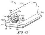
本発明の第2の態様では、接着剤で裏当てされた水平配線130’は、水平配線を提供するために、IBW用途又は光ファイバのために、ファイバトゥーザホームネットワークを支持するように1つ以上のRF信号チャネルを収容する。図6Bに示すように、水平配線130’は、これを通して提供される空洞をともなうコンジット部を有する主本体131’を含む。空洞は、コンジット部を通して延在する2つのボア部分128a、128bを形成するように、隔壁129によって分割することができる。それぞれのボア部分128a、128bは、IBW及び/又は有線通信ネットワークを支持するために、1つ以上の通信線(RF通信線、通信銅線、又は光ファイバ通信線)を収容するように寸法設定される。使用時、ダクトは、1つ以上の同軸ケーブル、通信銅線、光ファイバ、及び/又は電力線が予め装着されていてもよい。好ましい態様では、RF通信線は、約300MHz〜約6GHzの伝送周波数範囲を有するRF信号を送信するように構成される。2つ以上のボア部分を有する他の例示的な水平配線構造物は、PCT特許出願第PCT/US2012/034782号に記載され、その全体が参照により本明細書に組み込まれる。 In a second aspect of the present invention, the adhesive-backed horizontal wiring 130 'is one to support a fiber-to-the-home network for IBW applications or optical fibers to provide horizontal wiring. The above RF signal channels are accommodated. As shown in FIG. 6B, the horizontal wiring 130 'includes a main body 131' having a conduit portion with a cavity provided therethrough. The cavity can be divided by a
水平配線130’は、隔壁129内に形成された1つ以上のローブ付きの部分を含むことができる。それぞれのローブ付きの部分は、これを通して形成される補助のボア133a’、133b’を有することができる。補助ボアは、強化部材(図示せず)又は埋め込まれた電力線195を通すことができる。電力線は、絶縁又は非絶縁電線(例えば、銅線)とすることができる。電力線は、この構造化ケーブルによってサービスを受ける遠隔電子装置(遠隔無線又はWiFiアクセスポイントなどの)のために低電圧DC配電を提供することができる。電力線195が、隔壁129内に埋め込まれる場合、設置の間にダクトが伸張するのを防止するように、電力線は強化部材として作用することができる。隔壁内の電力線195は、ダクトの主本体131’内で切り取られた窓部を作製することによって、IDCタイプの接続(図示せず)によってアクセスされてもよい。電力線を隔壁内に埋め込むことにより、電線の場所が既知となり、かつ固定され、電力線への電気接続を作製するためのIDC又は他のコネクタの使用を容易にする。 The
分離されたボア部分128a、128bには、前に記載されるように、光ファイバ190又は絶縁した電線を装着することができる。分離されたボア部分は、ファイバと銅線との間のクラフト分離、又はネットワークの無線部分と統合型システムのFTTH部分との間のネットワーク分離を可能にする。 The separated bore
水平配線130’は、壁、又は床、天井、若しくはモールディングなどのその他の載置面に設置される、または載置されるときに、配線の支持を提供するフランジ又は類似の平坦部分も含む。水平配線130’は、中心に位置付けられたコンジット部の下にフランジ部分134a’、134b’が、位置付けられた二重フランジ構造物を含む。代替態様では、フランジは、一重のフランジ部分を有することができる。代替用途では、面内及び面外の曲がりのためにフランジの一部分を取り外すことができる。 The horizontal wiring 130 'also includes a flange or similar flat portion that provides or provides support for wiring when placed on or placed on a wall or other mounting surface such as a floor, ceiling, or molding. The horizontal wiring 130 'includes a double flange structure in which
好ましい態様では、フランジ部分134a’、134b’は、概して平坦面の形状を有する背面又は底面136’を含む。この平坦面は、接着剤層137’を使用して、載置面、壁、又は他の表面(例えば、ドライウォール、又は他の従来の建築材)に水平配線130’を接着するのに適した表面領域を提供する。接着剤層137’は、前に記載されるように、接着剤を含んでもよい。代替的な態様では、接着剤の裏当て層137’は取り外し可能なライナー138’を含む。使用時、このライナーを取り外し、接着剤層を載置面に貼り付けることができる。 In a preferred embodiment, the
図6Cは、統合型ネットワーク内で使用するための水平配線130’’の別の例示的な形態を示す。水平配線130’’は、それを通して提供される中央ボア132’’を有する主本体131’’を有するダクトの形態をとることができる。この態様では、中央ボア132’’は、その中に、有線システムのためのRF通信線及び光ファイバ通信線の形態の複数の光ファイバ190、並びに少なくとも2つの電力線195を収容するように寸法設定される。この例では、中央ボアは、8つの光ファイバ190a〜190hを収容するように寸法設定される。当然のことながら、用途によって、より多い又はより少ない数の光ファイバを利用することができる。光ファイバは、RoF又はFTTH信号を通すために、最適化することができる。例えば、光ファイバは、単一モード光ファイバを備えることができる。いくつかの用途では、複数モードファイバも利用することができる。 FIG. 6C shows another exemplary form of
別の代替の態様では、接着剤で打ちされた配線は、CAT5e、CAT6線などの、ツイストペア線上のイーサネット(登録商標)として構成される1つ以上の通信チャネルを更に含むことができる。別の代替案では、電力は、同軸線の1つ以上の導電性コア上で送信することができる。 In another alternative aspect, the glued wiring can further include one or more communication channels configured as Ethernet over twisted pair wires, such as CAT5e, CAT6 wires, and the like. In another alternative, power can be transmitted on one or more conductive cores of the coaxial line.
前に述べたように、水平配線130’’のダクトは、壁、又は床、天井、又はモールディングなどの他の載置面上に設置される又はこれらに載置されるときに、水平配線に対する支持を提供するためにフランジ又は類似の平坦な部分を含むことができる。好ましい態様では、フランジ部分134a’’、134b’’を有するフランジは、概して平坦面の形状をともなう背面又は底面を含む。好ましい態様において、接着剤層137’’は、上に記載するように、フランジ部分の底面139’’の全体又は少なくとも一部に配置される、エポキシ、転写接着剤、アクリル接着剤、感圧接着剤、両面テープ、又は除去可能な接着剤などの接着剤を含む。 As previously mentioned, the ducts of the horizontal wiring 130 '' when installed on or placed on walls or other mounting surfaces such as floors, ceilings, or moldings are relative to the horizontal wiring. A flange or similar flat portion may be included to provide support. In a preferred embodiment, the flange with
上に記載される水平配線は、MDUの廊下を通して電力線及び通信線を供給し、これによって、これらの線は、MDU内の様々な住戸においてアクセスすることができる。代替的には、水平配線は、電力線及び通信線を、例えば、オフィスビルディング、病院、又は教育施設などの他のタイプの建物内のノード点に供給することができる。次いで、信号は、2次水平配線の追加的な延長によって更に広めることができ、又は有線データ及び遠隔通信線は、薄型の遠隔通信ダクトによって個々の仕事の現場又はワークステーションに提供することができる。 The horizontal wiring described above provides power and communication lines through the MDU corridor, so that these lines can be accessed at various units within the MDU. Alternatively, horizontal wiring can provide power and communication lines to node points in other types of buildings, such as office buildings, hospitals, or educational facilities, for example. The signal can then be further spread by additional extension of secondary horizontal wiring, or wired data and telecommunications lines can be provided to individual work sites or workstations by thin telecommunications ducts. .
図8は、水平配線130によって供給された通信線及び/又は電力線にアクセスするために使用される例示的な入口点(POE)ボックス500のベース部分510を示す。POEボックス500は、壁のアクセスホール501の上方に、MDUの廊下内の1つ以上のアクセスポイントの近くに位置することができる。ベース部分510及びカバー(図示せず)は、硬質プラスチック材料又は金属から形成することができる。POEボックス500(カバー及びベース)は、薄型でかつ/又は装飾的な外側デザイン(壁取り付け式照明、ロゼット模様、インターレースノット、ミッションスクエア、貝殻、葉、又は流線的工業デザインなど)を有することができ、アクセスボックスは、それが設置される場所の審美的アピールを損なわないように、設置される全体的領域と色合わせすることができる。POEボックスは、所望により照明のための照明器具を備えてもよい。更に、カバーは、その外面にラミネートされた装飾的オーバレイフィルムを更に含んでもよい。そのようなフィルムは、3M(商標)Di Noc自己接着性ラミネート(3M Companyより入手可能)を備えることができ、周囲の構造の木目又は金属面を模倣することができる。 FIG. 8 shows a
POEボックス500は、POEボックス500の水平配線130上への簡単明瞭な載置を提供する、載置セクション520を含む。載置セクション520は、水平配線130の上及び上方に近接して嵌合するように構成される。このようにして、POEボックス500を、ダクト(及びその中に通信線)が設置された後に水平配線130に載置することができる。例えば、載置セクション520は、水平配線130の外形の上に嵌合するように構成される切り取り部分を含む。 The
ベースセクション510の内部内で、水平配線130内に配置される1つ以上の通信線は、特定の住戸の1つ以上のドロップワイヤ又はドロップファイバにアクセス及び接続することができる。この特定の例示的な態様では、水平配線130からの光ファイバ190は、特定の住戸からのFTTHドロップファイバケーブル193に連結される。通信ファイバ190は、水平配線のダクトのコンジット部に作製された同一の又は別個の切り取られた窓部127のいずれかを通してアクセスすることができる。1つの例示的な態様では、POEボックス500は、2つのファイバを水平配線から2つのFTTHドロップファイバケーブルに接続することができ、又は2つのファイバをRF信号を遠隔ソケットへ通すことになる2つの無線サービスファイバに接続することができ、又はPOEボックスは、両方の機能に同時に適応することができる。 Within the
一態様では、POEボックス500は、標準光コネクタを接続するために、光スプライス及び/又はファイバコネクタカップリング若しくはアダプタなどの1つ以上のカップリングデバイスに適応することができる。この例では、POEボックス500は、融着及び/又は機械的スプライスに適応するように構成された、1つ以上のスプライスホルダ191を含むことができる。POEボックス500のベース部分510は、1つ又はいくつかの異なるタイプの光ファイバコネクタアダプタ194を受容するための1つ以上のアダプタ又はカップリングスロット、ブラケット及び/又は板ばねを含むカップリング載置領域512も含むことができる。例示的な態様では、載置領域は互いにその上に積み重ねられた2つの光ファイバコネクタアダプタに適応することができる。代替態様では、スプライスホルダ及びカップリング載置領域はアクセスボックスの異なる領域に配置することができる。更なる代替では、カバー530(図9に示す)は、カップリング載置領域を含むように構成することができる。 In one aspect, the
POEボックス500は、アクセスしたファイバの経路を決定するためにファイバ余長収納セクション514を更に含むことができる。この例では、光ファイバ190は、1つ以上のファイバガイド515に沿って(載置セクションの左側又は右側のいずれかから)経路設定することができる。ファイバは、ファイバ余長収納セクションでベース部分510内、又はベース部分510の上に形成された曲げ半径制御構造516によって曲がり過ぎから保護される。ファイバ余長収納セクション514は、図8に示すように、長い及び短いファイバループ格納構造の両方を含むことができる。加えて、カップリング/アダプタの配向は、サービスファイバの入り口点と無関係にすることができる。また、ファイバの巻き方向は、アクセスボックス内に使用されるコネクタの載置構成と一致するように、ファイバ余長収納セクション514に提供されたクロスオーバーセクションを使用して逆にすることができる。一実施形態では、最大50フィート(15.2メートル)の900μm緩衝ファイバ及び最大3フィート(0.91メートル)の3mmファイバ余長をPOEボックス500内に収納することができる。代替態様では、カバー530(図9)も余長収納に適応することができる。 The
ファイバ190は、光ファイバを接続する際に利用されるカップリング機構のタイプによって、スプライスホルダ191に、又はファイバコネクタアダプタ194の載置領域に、ガイドすることができる。一実施形態では、住戸内FTTHシステムを供給するファイバは、ファイバコネクタアダプタを利用して接続することができる一方で、住戸内無線システム(図8に図示せず)をサービス提供するファイバは、光ファイバスプライス接続を利用することができる。ファイバコネクタアダプタ194は、アクセスボックスに提供されてもよく、又は設置者によって供給され、かつカップリング載置領域内に載置されてもよい。ファイバコネクタアダプタ194は、従来のインライン光ファイバカップラー又はアダプタ(すなわち、SCコネクタアダプタ、LCコネクタアダプタ、その他)を備えることができる。 The
図8の例では、光ファイバ190は、光ファイバコネクタ192aで現場終端処理される。例えば、コネクタ192aは、米国特許第7,369,738号に記載されているように、フェルール内に配置された、機械的スプライスでフィールドファイバにスプライスされている予め研磨されたファイバスタブを含む光ファイバコネクタを備えることができる。ファイバ190は、従来のSCコネクタなどのコネクタ192bを有するドロップケーブル193に、ファイバコネクタアダプタ194を介して、連結することができる。本明細書を考慮した技術の当業者には明らかであるように、コネクタ192a、192bの代わりにその他の従来のコネクタを利用することができる。 In the example of FIG. 8, the
この例示的なPOEボックスの設計は、追加的なスプライストレー、挿入物、又は余分な構成部分の必要なしに、POEボックス500内のスプライス及び/又はコネクタの配置を提供する。更に、コネクタカップリングは、余長収納領域に影響を及ぼすことなしに、独立に取り外す(例えば、ファイバ/電線を接続する/接続を外すために)ことができる。更に、あらゆる接続を全てPOEボックス500内に収納して、設置効率及び配線保護を強化することができる。 This exemplary POE box design provides for splice and / or connector placement within the
加えて、POEボックス500は、POEボックスによってサービスを受ける住戸内に供給される、水平配線130内の電力線を接続するためのスペースも提供することができる。例えば、水平配線130内に配置される電力線195を補助電力線196に接続する電源タップデバイス197は、アクセスホール501を通して住戸に入る。これらの補助電力線は、従来の低電圧電力線とすることができ、以下に記載される遠隔電子ユニットに電力を提供するために使用される。例示的な電源タップデバイスとしては、3M Company(St.Paul,MN)から入手可能な3M(商標)Scotchlok(商標)UB2Aコネクタが挙げられる。 In addition, the
代替的な態様では、入口点ボックス500としては、3M Company(St.Paul,MN)から入手可能な3M(商標)8686終端ボックスが挙げられる。 In an alternative aspect, the
遠隔ソケット600は、ここでより詳細に記載される。 The
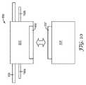
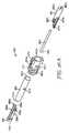
図10は、本発明の態様による、遠隔ソケットの概略図を示す。図11〜図24は、本発明の態様による、遠隔ソケットの第1の実施形態の異なる図を示す。図25〜図28は、本発明の態様による、遠隔ソケットの代替的な実施形態の異なる図を示す。図29〜図32は、本発明の態様による、遠隔ソケットの別の代替的な実施形態の異なる図を示す。 FIG. 10 shows a schematic diagram of a remote socket according to an aspect of the present invention. FIGS. 11-24 show different views of a first embodiment of a remote socket according to aspects of the present invention. FIGS. 25-28 illustrate different views of an alternative embodiment of a remote socket in accordance with aspects of the present invention. FIGS. 29-32 illustrate different views of another alternative embodiment of a remote socket in accordance with aspects of the present invention.
図10の概略図に示すように、遠隔ソケット600は、遠隔電子ユニット701’を受容するためのベース又はドッキングステーションとして作用するソケット601’を含む。この遠隔ソケット600は、遠隔電子装置の、本明細書に記載される通信ケーブルへの接続を容易にし、かつ管理する。遠隔ソケットインターフェースは、プラグアンドプレイのために設計され、これは、遠隔ソケットへの及び遠隔ソケットからの配線を変更することなしに、システム内に新しい無線を設置することができることを意味する。このプラグイン機能は、無線の保守及び無線の次世代のサービスへの更新を容易にする。(例えば、2Gから3Gへ、又は3Gから4Gへ、その他)。 As shown in the schematic diagram of FIG. 10,
ユニット701’は、本明細書では遠隔無線ユニットとも称され、この実施は本発明の好ましい態様を示す。しかしながら、本発明の代替的な態様では、遠隔電子ユニット701’は、無線(PCS、Cellular、GSM(登録商標)、その他)信号分配のための遠隔無線ユニット、802.11(Wi−Fi)伝送のための無線アクセスポイント、又は低電力無線センサユニット(ZigBeeデバイスなど)若しくは他のネットワーク可能なデバイス(例えば、CCTV、セキュリティ、警報センサ、RFIDセンサ、その他)を含んでもよい。ソケット601’は、簡単明瞭に遠隔電子ユニット‘701の接続を外すことも可能にする。このようにして、遠隔電子ユニット701は、ソケット601’にプラグ接続する最新のユニットと時々交換されてもよい。 Unit 701 'is also referred to herein as a remote radio unit and this implementation represents a preferred embodiment of the present invention. However, in an alternative aspect of the present invention, the remote
代替的な態様では、ソケット601’は、ソケット601’に接続された線の完全性を試験するための試験ジャンパとして作用することができるユニバーサルジャンパ(図示せず)を受容してもよい。加えて、ユニバーサルジャンパは、そうでなければ適合しない無線(又は他の電子的な装置)をユニバーサルジャンパを介してネットワーク内に接続するために利用されてもよい。 In an alternative aspect, socket 601 'may receive a universal jumper (not shown) that can act as a test jumper to test the integrity of the wire connected to socket 601'. In addition, universal jumpers may be utilized to connect otherwise incompatible radios (or other electronic devices) into the network via universal jumpers.
ソケット601’と遠隔電子ユニット701’との間の接続は、ソケットインターフェース602’及び遠隔無線インターフェース(プラグ)702’を介して達成される。ソケット601’は、いくつかの異なるタイプの通信ケーブル、すなわち、電子装置/無線ユニットのDC電力供給のための1つ以上の絶縁銅線、RF信号の分配のための1つ以上の光ファイバ、ツイストペア線、若しくは同軸ケーブル、及びRF信号のアンテナへの伝送のための1つ以上の同軸ケーブル若しくはツイン軸ケーブル、の接続を管理する。以下に更に詳細に記載されるように、本発明の異なる遠隔ソケット実施形態は、遠隔ソケット自体の中に含まれる単一の統合された作動機構の使用を通して、複数の媒体を同時に接続することができる。 The connection between the socket 601 'and the remote electronic unit 701' is achieved via a socket interface 602 'and a remote wireless interface (plug) 702'. The socket 601 'may comprise several different types of communication cables: one or more insulated copper wires for DC power supply of electronic devices / wireless units, one or more optical fibers for RF signal distribution, It manages the connection of twisted pair or coaxial cables and one or more coaxial or twin-axis cables for transmission of RF signals to the antenna. As described in further detail below, different remote socket embodiments of the present invention can simultaneously connect multiple media through the use of a single integrated actuation mechanism contained within the remote socket itself. it can.
遠隔電子ユニット701’は、水平のケーブル130などの構築されたケーブル上で送信される信号を、例えば、同軸ケーブル160a及び160bを介して、同一のソケットに取り付けられるアンテナによって放射することができるRF電気信号に変換する。しばしば、DASハブによって分配される無線信号は、上に記載されるように、直接変調されるアナログ光信号又はデジタル的に変調される光信号の形態で、光ファイバ上で送信される。代替的な態様では、ソケット601’は、無線信号を送信又は受容する統合型アンテナを含む。 The remote
好ましい態様では、無線ダウンリンク信号用に、ユニット701’内に収納された遠隔無線(例えば、図12に示す遠隔無線750を参照のこと)は、(例えば、PINフォトダイオードによる)光電気変換を含み、低ノイズ、RF前置増幅器及びRF電力増幅器が続く。これらのRF増幅器は、狭周波数帯又は広周波数帯(>200MHz)とすることができる。次いで、増幅されたRF信号は、無線信号を建物内のモバイルユーザーの装置へ放射するために、本明細書に更に記載される分散アンテナ800(図1)などのアンテナへ送られる。モバイルユーザーの装置(又はアップリンク無線信号)によって送信された無線信号は、遠隔ソケットに取り付けられる受信アンテナによって受信される。いくつかの場合では受信アンテナは、ダウンリンク送信アンテナと同一であり、ここでダウンリンクとアップリンク信号とは、送受切替器によって分けられ、他の場合には、それぞれの無線リンクのために別個の送信アンテナ及び受信アンテナがある。アップリンク信号は、低雑音増幅器によって増幅され、次いで、構築された配線システム上での送電のために信号形態に変換される。ファイバシステム上でのアナログ無線用に、半導体レーザー(例えば、垂直キャビティ面発光レーザー(VCSEL)、又は分布帰還型レーザーダイオード)を直接変調するために、アップリンクRF信号が使用される。レーザーからの光信号は、次いで、水平の構築された配線上での移送のためにファイバ内へ連結される。アップリンク及びダウンリンク送信のために、デジタル的に変調された光学的な信号及びデジタル的に変調された電気信号を含む、他の信号形態が使用されてもよい。 In a preferred aspect, a remote radio (eg, see
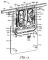
本発明の実施形態による遠隔ソケットの例示的な実施は、図11〜図24に示す遠隔ソケット600である。遠隔ソケット600は、遠隔電子ユニット701を受容するためのベース又はドッキングステーションとして作用する、ソケット601を有する壁に載置可能なユニットである。図11は、完全に係合され、かつ閉じた状態の遠隔ソケット600を示し、ここでソケット601と遠隔電子ユニット701との間の接続がなされている。本発明の好ましい態様では、遠隔電子ユニット701は、単一の動作で遠隔電子装置を起動するために、単にソケット601内にプラグ接続することができる。 An exemplary implementation of a remote socket according to an embodiment of the present invention is the
図11に示すように、ソケット601は、ソケット601の内容物を収納するカバー605を含む。カバー605は、好ましくは、審美的に心地良い外観で、かつフレーム部分611(図12及び図23を参照)の上にきちんと嵌る、薄型のカバーである。加えて、カバー605は、カバー605が水平配線130及び/又は同軸ケーブル160a、160bの上に嵌合することができるように、水平配線130及び(いくつかの態様では)同軸ケーブル160a、160bの外形にぴったり一致することができるカバー切り欠き608を含むことができる。カバー605は、好ましくは、硬質プラスチック材料から作製されるが、金属又は複合材料から作製されてもよい。カバー605は、以下により詳細に説明するように、接続プロセスの間、設置者を補助するために、所望により刻み目又は他の表面把持構造を含むことができる。 As shown in FIG. 11, the
遠隔電子ユニット701は、電子ユニット701の内容物を収納するカバー705も含む。カバー705は、好ましくは、審美的に心地良い外観を有する薄型のカバーである。加えて、カバー705は、空気が電子ユニット701に出入りするための空気流の通路を提供する、ベント708を更に含むことができる。カバー705は、好ましくは、硬質プラスチック材料から作製されるが、金属又は複合材料から作製されてもよい。カバー705好ましくは、支持プレート710(図12参照)の周辺の周りにきちんと嵌る。 The remote
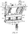
図12は、単純化のために、カバー605、705を取り外した遠隔ソケット600を示す。ソケット601は、カバー605の縁部と位置合わせする、剛性の金属又は硬質プラスチックから作製されるフレーム部分611を含む。以下に更に詳細に説明するように、フレーム部分611は、遠隔電子ユニット701の設置のために、おおよその位置合わせを提供する。支持プレート610は、ソケット601及びその中の構成部分のために更なる支持を提供し、かつ壁に対する背面載置面を提供する。 FIG. 12 shows
図12に示すように、例示的なソケット601は、単一の動作で、ソケットインターフェース602の、遠隔電子ユニットインターフェース702との接続を提供する、作動機構615を収納する。以下により詳細に記載されるように、作動機構615は、完全に統合され、別個の工具の必要を除去し、かつソケットインターフェース602の複数の媒体の、遠隔電子ユニットインターフェース702の対応する媒体との同時接続を可能にする機器として、構築することができる。本発明の代替的な実施形態では、作動機構は、遠隔電子ユニット内に配置することができる(例えば、図25〜図28参照)。 As shown in FIG. 12, the
遠隔電子ユニット701は、電子ユニット、ここでは支柱712上に載置され、建物又は構造物内に無線通信を提供する遠隔無線回路750を支持するための概して平面状の支持プレート710を含む。この例示的な態様では、遠隔無線回路750は、遠隔電子ユニットインターフェース702に連結されるプリント基板(PCB)又はカードとして構成される。当然のことながら、他の遠隔無線設計はユニット701によって適応される可能性があるので、遠隔無線の構築物は、PCB又はカードのものである必要はない。 The remote
好ましい態様では、遠隔無線は、ソケット/無線インターフェース602、702を介して遠隔電子ユニット701に接続されたDC電力線を介して電力を受けることができる。上に述べたように、遠隔無線750は、光電子変換及びRF電力増幅を提供するように構成することができ、ここで、増幅されたRF信号は、無線信号を建物内のモバイルユーザーの装置に放射するために、アンテナに送信される。モバイルユーザー装置によって送信された無線信号は、本明細書に記載される、構築された配線に取り付けられる受信アンテナによって受信され、構築された配線システム上で送信するために、アップリンク信号は、増幅され、かつ遠隔無線750によって信号形態に変換される。Fiber Span[Branchburg,NJ]からのAC231モジュールは、小型の、低出力の、広帯域の、ユニット701内に収納することができるRoF送受信機の一実施例である。代替的な態様では、遠隔無線750は、カメラ、センサ、アラーム、モニタ及びWi−Fi、ピコセル又はフェムトセルタイプの装置によって置き換えることができる。 In a preferred aspect, the remote radio can receive power via a DC power line connected to the remote
加えて、この例示的な態様では、遠隔電子ユニット701は、接続を作動させる前に、設置者に大まかな位置合わせを提供するために支持プレート710の頂部から延在するガイドフィンガー714などのガイド構造物を含むことができる。例えば、設置の間に、ガイドフィンガーは、ソケットがすでに載置されている壁とずれた初期の位置合わせを提供するために、支持プレート610から外向きに延在するソケット601のフレーム部分611の上に形成されたガイドピース609に接触することができる。 In addition, in this exemplary aspect, the remote
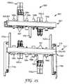
図13は、カバー605、705無しで、かつ単純化のために遠隔無線回路750を取り外した、遠隔ソケット600を示す。上に述べたように、例示的なソケット601は、ソケットインターフェース602の遠隔電子ユニットインターフェース702との接続を提供する、作動機構615を収納する。この例示的な態様では、作動機構615は、垂直支持バー617にわたって延びる横支持バー616を含む。この支持構造物は、ソケットインターフェース602のいずれかの側に位置する枢動機構618を中心として外向きに枢動する(支持プレート610から離れるように)。作動機構615は、遠隔電子ユニットインターフェース702と係合することができる2つの延在可能なガイドレール620(圧縮/引っ張りリンク619を介して垂直支持バー617に接続される)を上げ下げするように設計され、図16に関して、そして更に以下に、より詳細に記載される。好ましい態様では、作動機構615のための支持構造物は、カバー605の適切な位置付けを維持するのを助けるためにも使用され、これは、その下側(図示せず)に、作動機構のために、支持構造物上の様々な位置に形成されるガイド穴645内に受容される突出部を含むことができる。このガイド穴の係合は、ソケット601の設置後、カバーの望ましくない移動を防止する助けとなる。 FIG. 13 shows the
この実施形態の別の態様では作動機構615に対する支持構造物は、1つ以上の余長収納構造物660a、660bを支持するためにも使用することができる。余長収納構造物660a、660bは、水平配線130から引き出された光ファイバの余長分のための収納を提供し、これは以下により詳細に記載される。図13に示すように、余長収納構造物660a、660bは横バー616と枢動機構618との間に連結することができる。好ましい態様では、図16に示すように、余長収納構造物660a、660bは、ソケット601内で回転可能である。補助余長収納リール661(図14参照)などの更なる余長収納構造物、及び枢動するファイバガイドを、終端処理ファイバ上の軸方向の歪みを低減するために提供することができる。 In another aspect of this embodiment, the support structure for the
電力線などの、水平配線130からの他の媒体を、ソケットにおいて提供することができる。例えば、図13は、水平配線130内に配置される電力線を、補助電力線196a、196bを介してソケットインターフェース602に接続する電源タップデバイス197を示す。これらの補助電力線は、従来の低電圧電力線とすることができ、これは遠隔電子ユニット701に電力を供給するために使用される。例示的な電源タップデバイスとしては、3M Company(St.Paul,MN)から入手可能な3M(商標)Scotchlok(商標)UB2Aコネクタが挙げられる。 Other media from
本発明の代替的な態様では、電源タップが必要ないように、別個の専用の電力線を介してそれぞれの遠隔ソケット場所にDC電力を提供することができる。 In an alternative aspect of the present invention, DC power can be provided to each remote socket location via a separate dedicated power line so that no power strip is required.
加えて、図13に示すように、同軸ケーブル160a、160bは、ソケット601を通して、支持プレート610に沿って、ソケットインターフェース602に載置される同軸コネクタへと直接延在することができる。同軸ケーブル160a、160bは、図7A〜図7Cに関して本明細書に記載される接着剤で裏当てされた構築された配線と同様に構成することができる。代替的には、同軸ケーブルは、接着剤により裏当てされている必要はなく、Times Microwave,Systems(Wallingford,CT)から入手可能な、LMR195又はLMR240などの従来の、小型の同軸ケーブルから成ってもよい。 In addition, as shown in FIG. 13, the
図14は、構築された配線を図から除去した、ソケット601のより詳細な図を示す。このように、フレームの切り欠き612a、612bを見ることができ、ここで、これらの切り欠きは、ソケット601から経路設定された同軸ケーブル160a、160bの外面の上に嵌合するように構成される。この実施形態の好ましい態様では、支持プレート610は、同軸ケーブル160a、160bが、ソケット601から出て、同軸ケーブル160a、160bの接着剤の裏当て部が壁面と接触できるように経路を提供するケーブルチャネル614a、614b(図22も参照)を含むことができる。加えて、支持プレート610は、載置壁を通して持ち込まれる場合がある、追加的な配線又は他の装置にアクセスするために利用することができる、背面アクセスポート613(図22も参照)を含む。図14は、支持プレート610に載置され、延在可能なガイドレール620を更に支持するために提供される、ガイドレール支持ブラケット625a、625bのより明瞭な図も提供する。加えて、ソケット601内で追加的な光ファイバを収納及び経路設定するのを補助するために、補助余長収納リール661を支持プレート610上に配置することができる。 FIG. 14 shows a more detailed view of the
図15は、支持プレート610を取り外した、ソケット601のより詳細な図を示す。この例示的な態様では、余長収納構造物660aは、ファイバリール662a及び662bを含み、余長収納構造物660bは、ファイバリール662c及び662dを含む。光ファイバ190a、190bは、遠隔電子ユニットインターフェース702への接続のために、水平配線(単純化のため、この図では図示せず)から除去される。特に、光ファイバの余長分は、収納され、かつそれぞれのファイバを、現場終端処理光学コネクタ192a、192b(以下により詳細に記載される)を使用して終端処理することができるように余長収納構造物660aを介して経路設定される。加えて、ファイバリール662a〜662dのそれぞれは、光ファイバがそれらの収納リールから変位するのを防止するのを助ける1つ以上の保持構造物663を含む。代替的な態様では、いくつかの用途用に、ソケット601は、ソケットの位置で水平配線から除去された、最大4つの光ファイバを収容することができる。 FIG. 15 shows a more detailed view of the
本発明の例示的な態様では、インターフェース602、702のそれぞれは、2部品の構造物を含み、ここで、インターフェース本体603、703は、インターフェース本体上に載置されるマルチメディア構成部分に追加的な支持を提供する金属薄板などの硬質材料から形成されるインターフェース骨格604、704によって支持される。このようにして、インターフェース本体要素は、全く同一の構造を有する(例えば、同一の成形プロセスで作製される)成形されたプラスチック部品を備え、それぞれのインターフェース本体は、複数の媒体コネクタを受容するための複数のポートを有する。結果として、接続の間に、ソケットインターフェース間の位置合わせを、より容易に達成することができる。 In an exemplary aspect of the invention, each of the
図11〜図15は、インターフェース602、702を接続された状態で示す。図16では、インターフェース602、702を、分離した、接続を外した状態で示す。加えて、図16は、手前に引かれた支持バー616、617を示し、これは、矢印629の方向に延在可能なガイドレール620a、620bを下げる。示すように、圧縮/引っ張りリンク619は、垂直支持バー617と延在可能なガイドレール620a、620bとの間の接続を維持する。ガイドレールは、ガイドレール支持ブラケット625a、625bによって更に支持され、そのそれぞれは、枢動機構618を介した延在可能なガイドレール620a、620bの上げ下げを可能にし、ガイドレール支持ブラケット625a、625bに固定された1つ以上の長手方向スロット626a、626bを含む。ガイドレール支持ブラケット625a、625bは、従来の締結具(図示せず)を介して支持プレート610(図16に図示せず)に固定することができる。 11 to 15 show the
図16は、ソケットインターフェース602(図17及び図18に示す中央ガイドピンポート631を参照)の中央部分に配置される中央ガイドピン630も示す。好ましい態様では、中央ガイドピン630は、遠隔電子ユニットインターフェース702内に形成される中央ガイドポート731によって受容される。中央ガイドピンは、インターフェース本体相互の横方向の滑動を防止するように構成することができるだけでなく、接続の間、インターフェースを位置合わせするのを助ける。加えて、図16は、余長収納構造物660a、660bを、部分的に回転した状態で示す。 FIG. 16 also shows a
図17は、ソケット及び遠隔電子ユニットインターフェース602、702を、分離した、接続を外した状態で示す。加えて、作動機構の支持バーは、単純化のために除去され、ソケットインターフェース骨格604も同様に除去される。この例示的な態様に示すように、延在可能なガイドレール620a、620bは、それぞれに、遠隔電子ユニットインターフェース702上に提供される対応する係合スロット721と係合するラッチピン621を含むことができる。それぞれの延在可能なガイドレールは、ソケットインターフェース本体603の端部の突出部633の間に形成される陥凹領域623を通して滑動することができる。遠隔電子ユニットインターフェース本体703の突出部733の間に形成される対応する陥凹部723は、係合スロット721を有する構造物を支持することができる。図17も、延在可能なガイドレール620a、620bが枢動機構618を通過することができる、それぞれがガイドレールスロット622a、622bを含む、延在可能なガイドレール620a、620bを示す。 FIG. 17 shows the socket and remote electronic unit interfaces 602, 702 in a disconnected, disconnected state. In addition, the support bar of the actuation mechanism is removed for simplicity, and the
図17及び図18は、遠隔ソケットで利用することができるいくつかの例示的なコネクタのより詳細な図を提供する。図17及び図18は、ソケットインターフェース602及び遠隔電子ユニットインターフェース702の、分離した、接続を外した状態である。上に述べたように、ソケットは、いくつかの異なるタイプの通信ケーブル、すなわち、電子装置/無線ユニットのDC電力用の1つ以上の絶縁銅線、RF信号の分配用の1つ以上の光ファイバ、ツイストペア線、又は同軸ケーブル、及びアンテナへのRF信号の伝送用の1つ以上の同軸又はツイン軸ケーブルの接続を取り扱う。このように、インターフェース602、702は、これらの異なる媒体のそれぞれのための対応するコネクタを含む。例えば、ソケットインターフェース602は、遠隔ソケットを分散アンテナの1つ以上にリンクする同軸ケーブルに接続を提供するための同軸コネクタ166a、166bを含む。例えば、Amphenol RF(Danbury、CT)によって作製される市販のMMCXコネクタを利用することができる。加えて、遠隔電子ユニットに電力を供給するために、低電圧電力線コネクタ198a、198bを、ソケットインターフェース602上に提供することができる。例えば、Molex 093シリーズのプラグアンドソケットレセプタクル及び/又はその構成部分などの市販の電力ピンコネクタを利用することができる。他の同様に構築された市販の電源コネクタに利用することができる。 17 and 18 provide a more detailed view of some exemplary connectors that can be utilized with a remote socket. 17 and 18 show the
加えて、現場終端処理光ファイバコネクタ、192a、b及び192c、dを、RF光ファイバ信号を遠隔電子ユニットに連結するために提供することができる。この例示的な態様では、コネクタ192a、b及び192c、dは、3M Company、St.Paul,MNから入手可能な、インターフェース本体603に載置されるコネクタアダプタ194a及びインターフェース本体703に載置されるコネクタアダプタ194bなどの標準LC二重ファイバコネクタアダプタに載置される、二重LCコネクタである。代替的な態様では、異なる光学的コネクタの形式が利用されてもよい。 In addition, field terminated fiber optic connectors, 192a, b and 192c, d can be provided for coupling RF fiber optic signals to remote electronic units. In this exemplary embodiment,
上述のコネクタのそれぞれは、本体内に形成される対応するポートを介して、インターフェース本体603、703上に載置することができる。異なるコネクタ又はコネクタマウントを適所に固定するために様々な締結具606、706を使用することができる。更なる例示的な態様では、光ファイバコネクタ用に、ファイバコネクタアダプタをそれらの載置位置に固定するのを助けるために、引込載置部材607、707がインターフェース本体603、703の表面と向き合うインターフェース上に提供される。加えて、引込載置部材607、707は、接続プロセスの間にコネクタアダプタ内に接近するLCコネクタをガイドするために、先細の又は傾斜した構築物を有することができる。 Each of the connectors described above can be mounted on the
代替的な態様では、ソケットインターフェース光ファイバコネクタ192a、bは、ソケットインターフェース602に載置される、形状因子の小さいプラグ接続可能な(SFP)モジュールにプラグ接続することができる。SFPモジュールは、接続すると、光信号を電気信号に変換し、これは次いで、遠隔電子ユニット701によって受信される。この代替的な態様は、遠隔電子ユニットを用いる、全て電気的なインターフェースを許容する。 In an alternative aspect, the socket interface
図19は、ソケットインターフェース本体603と遠隔電子ユニットインターフェース本体703との、接続した状態の、より詳細な図を示し、ここで媒体のそれぞれの形態は、本明細書に記載される例示的なコネクタを介して接続される。特に、ソケットインターフェース同軸コネクタ166a、166bは、それらの相手側の遠隔電子ユニットコネクタ166c、166dに接続され、ソケットインターフェース電源コネクタ198a、198bは、それらの相手側の遠隔電子ユニット電源コネクタ198c、198dに接続され、ソケットインターフェース光ファイバコネクタ192a、b、192c、dは、それらの相手側の遠隔電子ユニット光ファイバコネクタ192e、f、192g、hに接続される。 FIG. 19 shows a more detailed view of the
別の好ましい態様では、遠隔電子ユニット701をソケット601と接続するための例示的な設置プロセスは、図20〜図24に関して、ここで記載されることになる。この例では、遠隔電子ユニット701は、ファイバ上のRF理論に従って操作される遠隔無線ユニットを含む。図20は、例示的なソケット601と例示的な遠隔電子ユニット701との、分離された、接続を外した状態を示す。ソケット601は、建物内の適した位置で、建物内に設置される水平配線130の位置と一致する、室内又は廊下に設置される。 In another preferred aspect, an exemplary installation process for connecting remote
切り取られた窓部159(図21参照)は、直接的に変調されたアナログ光信号又はデジタル的に変調された光信号を通すために設計されるダクト内に配置される1つ以上の光ファイバにアクセスを提供するために、水平配線130内に作製することができる。次いで、ソケット601は、ソケット支持プレート610を通して載置壁内に延在するネジ又はボルトなどの従来の締結具(図示せず)を介して切り取られた窓部の位置に載置することができる。ソケット601は、切り取られた窓部の上に嵌合し、ソケット601が設置されると、水平配線内の残りのファイバは、剥き出しにはならない。図示しないが、水平配線130からアクセスした1つ以上のファイバの余長分を、余長収納構造物660a、660b上に経路設定し、かつ収納することができる。例えば、2つの光ファイバは、上に記載される現場終端処理LC光コネクタ192a、bなどの、光ファイバコネクタ内で現場終端処理することができる。例示的な光ファイバ現場終端処理プロセスは、米国特許公報第2009−0269014号に記載され、その全体が参照により本明細書に組み込まれる。 The cut window 159 (see FIG. 21) is one or more optical fibers disposed in a duct designed to pass a directly modulated analog optical signal or a digitally modulated optical signal. Can be fabricated in
加えて、水平配線130内に配置される電力線は、電源タップ197によるなどしてタップ接続し、補助電力線196a、196bなどの終端処理電力線に接続することができる。補助電力線196a、196bの終端処理端部は、上に記載されるコネクタ198a、198bなどの電源コネクタに接続することができる。また、同軸コネクタ166a、166bなどのRF同軸コネクタは、接着剤で裏当てされた同軸ケーブル160a、160b(図21に示す)、又は代替的な同軸コネクタなどの同軸ケーブルに連結することができる。本発明の例示的な設置プロセスでは、異なる媒体がソケットインターフェース602のコネクタに連結される順番は問題ではない。 In addition, the power lines arranged in the
ソケットインターフェース602への接続が完了したとき、カバー605は、図22及び図23に示すような従来のラッチ605aを介して、作動機構の支持バー部分上に配置することができる。図21〜図23に示すように、ソケットカバー605及び作動機構615は、延在可能なガイドレールを下がった位置にするために、壁から引くことができる。好ましい態様では、ソケットの幅は、約4インチ(10.2cm)〜約6インチ(15.2cm)とすることができ、これにより、設置者は片手を使用してカバー605を把持して、作動機構を前方に引いてもよい。 When the connection to the
ここで遠隔無線ユニット701として構成される遠隔電子ユニットは、次いでソケット601に接続することができる。好ましい態様では、遠隔無線ユニット701は、遠隔無線ユニットインターフェース702にすでに接続された、その構成部分を備えるコネクタ付きとすることになる。遠隔無線ユニット701は、初期の位置合わせ工具としてガイドフィンガー714を使用して、載置壁に沿って又はこれとずれて、上向きにガイドすることができる。遠隔無線ユニット701が、ソケット601のより近くに来ると、遠隔無線ユニット701は、延在可能なガイドレール(例えば、背面側からの初期接触を示す図22を参照)に接触することになる。ソケット(例えば、図17参照)の両側のラッチピン621は、係合スロット721によって受容され、かつ中央ガイドピン630は、初期にはポート731によって受容される。 The remote electronic unit configured here as the
この段階で、遠隔無線ユニット701は延在可能なガイドレールによって支持される。単一の動作で異なる媒体接続の全ての接続を同時に作動させるためには、設置者は単にカバー605を載置壁に向かって押せばよく、これによって延在可能なガイドレールが上がり、遠隔電子ユニットインターフェース702が、ソケットインターフェース602(例えば、図24参照)と接触するようになる。カバー605の縁部が側面フレーム部分611と同じ高さになると、接続は、完了する。図示しないが、カバーは、望ましくない又は意図しない無線ユニットのソケットからの接続の切断を防止するために、セキュリティ機構として使用するためのピン又はロックを含むことができる。当然のことながら、後で接続を外す必要がある場合、カバーを前方に(壁から離れるように)引くことができ、遠隔電子ユニットは、簡単明瞭な除去のために下げられる。 At this stage, the
上に述べたように、ソケット接続作動機構は、好ましくは、ソケット上に位置するが、代替的な態様では、作動機構は、遠隔電子ユニット上に提供することができる。加えて、作動機構の構築は、異なってもよく、それでも単一の動作でソケットインターフェースの遠隔電子ユニットインターフェースとの接続を提供することができる。例えば、図25〜図28は、ソケットインターフェース601’’及び一体型の作動機構715を有する遠隔電子ユニットインターフェース701’’を含む、代替的な無線ソケット600’’を示す。 As noted above, the socket connection actuation mechanism is preferably located on the socket, but in an alternative aspect, the actuation mechanism can be provided on the remote electronic unit. In addition, the construction of the actuation mechanism may be different and still provide a connection with the remote electronic unit interface of the socket interface in a single operation. For example, FIGS. 25-28 illustrate an
この代替的な態様では、ソケット601’’及び遠隔電子ユニット701’’のためのカバー、無線回路、及び一般的な支持構造物は、図11〜図24に関して示すものと類似の構築物を有することができるが、単純化のために除去されている。図25は、ソケットインターフェース602’’及び遠隔電子ユニットインターフェース702’’を分離した、接続を外した状態で示す。上に記載される実施形態と類似して、ソケット601’’は、いくつかの異なるタイプの通信ケーブル、すなわち、電子装置/無線ユニットのDC電力供給のための1つ以上の絶縁銅線、RF信号の分配のための1つ以上の光ファイバ、ツイストペア線、又は同軸ケーブル、及びRF信号のアンテナへの伝送のための1つ以上の同軸若しくはツイン軸ケーブルの接続を取り扱う。このように、インターフェース602’’、702’’は、これらの異なる媒体のそれぞれのための対応するコネクタを含む。上に記載されるように、インターフェース本体(603、703)及び骨格(604、704)は、同一の構築物を有することができることに留意されたい。 In this alternative embodiment, the cover, radio circuit, and general support structure for
この例では、ソケットインターフェース602’’は、遠隔ソケットを分散アンテナの1つ以上にリンクする同軸ケーブルに接続を供給する同軸コネクタ166a、166bを含む。例えば、市販のMMCコネクタを利用することができる。加えて、遠隔電子ユニットに電力を供給するために、低電圧電力線コネクタ198a、198bを、ソケットインターフェース602’’上に提供することができる。例えば、Molex 093シリーズのプラグアンドソケットレセプタクル及び/又はその構成部分などの市販の電力ピンコネクタを利用することができる。 In this example,
加えて、現場終端処理光ファイバコネクタ、192a、b及び192c、dを、RF光ファイバ信号を遠隔電子ユニットに連結するために提供することができる。この例示的な態様では、コネクタ192a、b及び192c、dは、3M Company、St.Paul,MNから入手可能な、インターフェース本体603に載置されるコネクタアダプタ194a及びインターフェース本体703に載置されるコネクタアダプタ194bなどの標準LC二重ファイバコネクタアダプタに載置される、二重LCコネクタである。 In addition, field terminated fiber optic connectors, 192a, b and 192c, d can be provided for coupling RF fiber optic signals to remote electronic units. In this exemplary embodiment,
上述のコネクタのそれぞれは、本体内に形成される対応するポートを介して、インターフェース本体603、703上に載置することができる。異なるコネクタ又はコネクタマウントを適所に固定するために、様々な締結具を使用することができる。更なる例示的な態様では、光ファイバコネクタ用に、ファイバコネクタアダプタをそれらの載置位置に固定するのを助けるために、引込載置部材607、707がインターフェース本体603、703の表面と向き合うインターフェース上に提供される。加えて、引込載置部材607、707は、接続プロセスの間にコネクタアダプタ内に接近するLCコネクタをガイドするために、先細の又は傾斜した構築物を有することができる。 Each of the connectors described above can be mounted on the
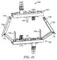
この代替的な遠隔ソケットの作動機構715は、遠隔電子ユニット701’’と一体化される。作動機構715は、インターフェース本体703を超えて延在し、ソケットインターフェース602’’上にラッチするように構成される一対の折り畳みラッチアーム716a及び716bを含む。図26に示すように、折り畳みラッチアーム716a及び716bは、枢動点718を介して接合されたそれぞれの2つのアームセグメントを含む。折り畳みラッチアーム716a及び716bのそれぞれの遠位端は、それぞれ1つ以上の係合スロット719a及び719bを更に含むことができる。接続順序の間に、折り畳みラッチアーム716a及び716bは、図26に示すように展開される。折り畳みラッチアーム716a及び716bは、係合スロット719a、719bが、それぞれのソケットインターフェース602’’のそれぞれの端部に載置されるクロスピン(図では隠れている)と係合されるまで、ソケットインターフェース602’’(上に記載されるように、載置壁にすでに載置されている)に向かって取り出される。加えて、ガイドレール720a、720bは、ソケットインターフェース602’’のそれぞれの端部に形成された陥凹部分内に滑動して入る。図26及び図27は、ソケットインターフェース602’’の中央部分に配置される中央ガイドピン630も示す。好ましい態様では、中央ガイドピン630は、遠隔電子ユニットインターフェース702’’内に形成される中央ガイドポート731によって受容される。中央ガイドピンは、インターフェース本体相互の横方向の滑動を防止するように構成することができるだけでなく、接続の間、インターフェースを位置合わせするのを助ける。代替的には、中央ガイドピン630は、遠隔電子ユニットインターフェース702’’内に配置することができ、ソケットインターフェース602’’内に形成される中央ガイドポートによって受容することができる。 This alternative remote socket actuation mechanism 715 is integrated with the remote
係合が生じたとき、折り畳みラッチアーム716a、716bは、矢印629の向きに下向きに動き、遠隔電子ユニットインターフェース702’’をソケットインターフェース602’’に向かって持ち上げ、ひいては、同軸コネクタ166aをコネクタ166cへ、同軸コネクタ166bをコネクタ166dへ、電源コネクタ198a及び198bをそれぞれコネクタ198c、198d、へ、並びに光ファイバコネクタ192a、b及び192c、dをそれぞれコネクタ192e、f及び192f、g、への接続を同時に開始する。 When engagement occurs, the
図28は、ソケットインターフェース601’’及び遠隔電子ユニットインターフェース701’’を、完全に接続した状態で、折り畳みラッチアーム716a、716bが元の位置にそれらが折り畳まれた状態で示す。この代替的な態様では、遠隔電子ユニット701’’のためのカバーは、取り外し可能であり、これにより、完全な接続が行われた後、カバーはユニット上の元の位置とすることができる。 FIG. 28 shows the
図29〜図32は、作動機構615とは異なる構築物をともなう、一体型の作動機構615’’’を有するソケットインターフェース601’’’と、遠隔電子ユニットインターフェース701’’’とを含む、代替的な無線ソケット600’’’を示す。この代替的な態様では、ソケット601’’’及び遠隔電子ユニット701’’’のためのカバー、無線回路、及び一般的な支持構造物は、図11〜図24に関して示すものと類似の構築物を有することができるが、単純化のために除去されている。図29は、ソケットインターフェース602’’’及び遠隔電子ユニットインターフェース702’’’を分離した、接続を外した状態で示す。上に記載される実施形態と類似して、ソケット601’’’は、いくつかの異なるタイプの通信ケーブル、すなわち、電子装置/無線ユニットのDC電力供給のための1つ以上の絶縁銅線、RF信号の分配のための1つ以上の光ファイバ、ツイストペア線、又は同軸ケーブル、及びRF信号のアンテナへの伝送のための1つ以上の同軸若しくはツイン軸ケーブルの接続を取り扱う。このように、インターフェース602’’’、702’’’は、これらの異なる媒体のそれぞれのための対応するコネクタを含む。インターフェース本体(603、703)及び骨格(604、704)は、図11〜図24の実施形態に関して、上に記載されるものと同一の構築物を有してもよいことに留意されたい。 FIGS. 29-32 show alternatives including a
この例では、ソケットインターフェース602’’’は、上に記載されるこれらのコネクタと類似の、遠隔ソケットを分散アンテナの1つ以上にリンクする同軸ケーブルに接続を提供する同軸コネクタ166a、166bを含む。加えて、遠隔電子ユニットに電力を供給するために、上に記載されるこれらのコネクタと類似の、低電圧電力線コネクタ198a、198bを、ソケットインターフェース602’’’上に提供することができる。 In this example, the
加えて、上に記載されるこれらの光ファイバコネクタと類似の、現場終端処理光ファイバコネクタ、192a、b及び192c、dを、RF光ファイバ信号を遠隔電子ユニットに連結するために提供することができる。上に記載されるものと類似のコネクタアダプタ194a、194bを利用することもできる。 In addition, field terminated fiber optic connectors, 192a, b and 192c, d, similar to those described above, may be provided for coupling RF fiber optic signals to remote electronic units. it can.
上述のコネクタのそれぞれは、本体内に形成される対応するポートを介して、インターフェース本体603、703上に載置することができる。異なるコネクタ又はコネクタマウントを適所に固定するために、様々な締結具を使用することができる。更なる例示的な態様では、光ファイバコネクタ用に、上に記載されるものと類似した引込載置部材も利用することができる。 Each of the connectors described above can be mounted on the
この代替的な遠隔ソケットの作動機構615’’’は、ソケット601’’’と一体化される。作動機構615’’’は、圧縮引っ張りリンク619’’’(図30参照)を介して、延在可能なガイドレール620a及び620bを、矢印629の方向に下げかつ上げる一対の枢動アーム617a’’’及び617b’’’を含む。枢動アーム617a’’’及び617b’’’は、枢動アームが引き出されたとき、延在可能なガイドレールが下がるような、図30に示す矢印628の方向(すなわち、載置されるとき、載置壁の面に平行な)の動きを有する。下がったとき、ガイドレール620a及び620bは、対応する係合スロット721と係合するように、遠隔電子装置インターフェース702’’’の端部に配置されるピン621を利用する。 This alternative remote
図30及び図31は、ソケットインターフェース602’’’の中央部分に配置される中央ガイドピン630も示す。好ましい態様では、中央ガイドピン630は、遠隔電子ユニットインターフェース702’’’内に形成される中央ガイドポート731によって受容される。中央ガイドピンは、インターフェース本体相互の横方向の滑動を防止するように構成することができるだけでなく、接続の間、インターフェースを位置合わせするのを助ける。代替的には、中央ガイドピン630は、遠隔電子ユニットインターフェース702’’’内に配置することができ、ソケットインターフェース602’’’内に形成される中央ガイドポートによって受容することができる。 FIGS. 30 and 31 also show a
ガイドレールピン621の係合スロット721との係合が生じると、枢動アーム617a’’’及び617b’’’は、内向きに(お互いに向かって)動き、延在可能なガイドレール620a及び620bを上げ、遠隔電子ユニットインターフェース702’’’をソケットインターフェース602’’’に向かって上げ、ひいては、同軸コネクタ166aをコネクタ166cへ、同軸コネクタ166bをコネクタ166dへ、電源コネクタ198a及び198bをそれぞれコネクタ198c、198dへ、並びに光ファイバコネクタ192a、b及び192c、dをそれぞれコネクタ192e、f及び192f、g、への接続を同時に開始する。図32は、ソケットインターフェース601’’’及び遠隔電子ユニットインターフェース701’’’を、完全に接続した状態で、枢動アーム617a’’’及び617b’’’がそれらの元の位置に戻った状態で示す。この代替的な態様では、ソケット701’’のためのカバーは、取り外し可能であり、これにより、完全な接続が行われた後、カバーはソケット上の元の位置とすることができる。 When engagement of the
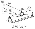
上述するように、遠隔ソケットは、接着剤で裏当てされた同軸ケーブルを介して統合型ネットワークの分散アンテナ800に連結することができる。好ましい態様では、同軸ケーブル160(図1及び図2)は、遠隔ソケット内に配置されるアクティブな遠隔電子装置と環境への無線信号伝播のためのブロードバンド分散アンテナのうちの1つ以上との間で、無線信号を通す。同軸ケーブル160は、Times Microwave Systems(Wallingford,CT)から入手可能なLMR−240同軸ケーブル、LMR−300同軸ケーブル、LMR−400同軸ケーブル、又は接着剤で裏当てされた同軸ケーブルなどの標準同軸ケーブルとすることができる。例示的な接着剤で裏当てされた同軸ケーブル160、160’は、図7A及び図7Bに関して更に詳細に記載される。 As described above, the remote socket can be coupled to the distributed
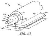
1つの例示的な態様では、接着剤で裏当てされた同軸ケーブル160を、図7Aに示す。接着剤で裏当てされた同軸ケーブル160は、長手方向にこれを通って延在するボア163を有するコンジット部162を含む。接着剤で裏当てされた同軸ケーブル160は、最長数十メートル(用途に応じて)又は更には数百メートルの長さ(L)を有してもよい細長い構造物である。ボア163は、その中に配置される1つ以上の同軸線を収容するように寸法設定される。この態様では、同軸コア170aは、接着剤で裏当てされた同軸ケーブルのコンジット部のボア内に適応することができる。同軸コアは、誘電体層172によって包囲される中央内部導体171を備える。内部導体は、誘電体層によって包囲される単一の導電性要素若しくは電線、又は複数のより小さいゲージの中実金属線とすることができる。シールド層173は、誘電体層172の上に配置することができる。シールド層は、接着剤で裏当てされた同軸ケーブルを接地するのを助け、ケーブルのインピーダンスを制御するのを助け、かつ電磁干渉又はケーブルからの放出を防止することができる。シールド層は、第1の内部導体の周りを包む、誘電体層の上に配置される金属箔、又は編組若しくは編んだ金属層、又はこれらの組み合わせの形態とすることができる。 In one exemplary embodiment, an adhesive-backed
コンジット部162は、概して円形の断面を有してもよいが、代替的な実施形態では、2軸コア構造又は多軸コア構造のいずれかとともに使用される場合、長方形、正方形、又は平たいリボン状の断面などの別の形状を有してもよい。
一態様では、接着剤で裏当てされた同軸ケーブル160は、ポリ塩化ビニル(PVC)などの高分子材料で形成された連続構造であり、それにより柔軟かつ丈夫である。別の態様では、接着剤で裏当てされた同軸ケーブル160は、例えば、Elastollan 1185A10FHFのようなポリウレタンエラストマーなどの例示的な材料から成ってもよい。更に別の態様では、接着剤で裏当てされた同軸ケーブル160は、所望により1つ以上の難燃添加物を含むポリオレフィン材料から成ってもよい。このように、接着剤で裏当てされた同軸ケーブル160は、ひび又は割れなしに、角及び他の構造物を回ってガイドされ、かつ曲げることができる。接着剤で裏当てされた同軸ケーブル160は、同軸コア構造物の周りにコンジット部を押出成形することによって連続的に形成することができる。 In one aspect, the adhesive-backed
接着剤で裏当てされた同軸ケーブル160は、壁、又は床、天井、若しくはモールディングなどの他の載置面上に設置又は載置されるときに、接着剤で裏当てされた同軸ケーブル160に支持を提供するためのフランジ164又は類似の平坦部分も含む。ほとんどの用途では、載置面は、概して平坦である。載置面は、その上に形成されたテクスチャ又は他の構造を有してもよい。他の用途では、載置面は、ピラー又はカラムに見られるような湾曲部を有してもよい。フランジ164は、ダクトの長手方向軸に沿って延在する。例示的な接着剤で裏当てされた同軸ケーブル160は、フランジ部分164a及び164bが、中央に位置するコンジット部162の下に位置する(使用時)二重フランジ構造を含む。代替態様では、フランジは、一重のフランジ部分を有することができる。代替用途では、面内及び面外の曲がりのためにフランジの一部分を取り外すことができる。代替的な態様では、フランジはコンジット部162を超えて延在せず、依然としてその平坦な縁部に留まり、したがって「D」字型ダクトを形成する。 The adhesive-backed
好ましい態様では、フランジ164は、概して平坦な表面形状を有する背面又は底面165を含む。この平坦面は、接着剤層161を使用して、接着剤で裏当てされた同軸ケーブル160を、載置面、壁、又は他の表面(例えば、ドライウォール又は他の従来の建築材料)に接着するのに適した表面領域を提供する。例えば、本発明の好ましい態様では、接着剤層161は、底面165の全体又は少なくとも一部の上に配置される転写接着剤又は両面テープなどの感圧性接着剤を備える。これらのタイプの接着剤は、載置面への塗布の際に巨視的な流れの挙動を示さず、したがって載置面への塗布の際に実質的に寸法を変更しない。このようにして、塗布されたダクトの審美的な質は、維持される。代替的には、接着剤層は、エポキシから成ってもよい。 In a preferred embodiment, the
一態様では、底面165は、水平配線について上に記載されるもののような、取り外し可能なライナー166を有する接着剤層161で裏当てされる。 In one aspect, the
更なる代替的な態様では、これを通って長手方向に延在するボア163を有するコンジット部162を含む、代替的な接着剤で裏当てされた同軸ケーブル160’が、図7Bに示される。ボア163は、その中に配置される1つ以上の同軸コア構造物170bを収容するように寸法設定される。この態様では、同軸コア170aは、接着剤で裏当てされた同軸ケーブルのコンジット部のボア内に収容することができる、TESSCO Technologies Incorporated(Hunt Valley,MD)から入手可能なLMR−300同軸ケーブルなどの従来の同軸ケーブルとすることができる。同軸コア構造物170bは、誘電体層172によって包囲される中央内部導体171を含む。内部導体は、誘電体層によって包囲される単一の導電性要素若しくは電線、又は複数のより小さいゲージの中実金属線とすることができる。シールド層173は、誘電体層172の上に配置することができ、絶縁ジャケットをシールド層の上に配置することができる。 In a further alternative embodiment, an alternative adhesive-backed coaxial cable 160 'is shown in FIG. 7B that includes a
接着剤で裏当てされた同軸ケーブル160’は、上に記載されるもののような壁又は他の載置面の上に設置、又は上に記載されるもののような壁又は他の載置面に載置されるときに、接着剤で裏当てされた同軸ケーブル160’に支持を提供するためのフランジ164又は類似の平坦な部分も含む。フランジは、ダクトの長手方向軸に沿って延在する。例示的な接着剤で裏当てされた同軸ケーブル160’は、(使用時)中心に配置されたコンジット部の下に位置するフランジ部分164a及び164bをともなう二重フランジ構造を含む。代替態様では、フランジは、一重のフランジ部分を有することができる。代替用途では、面内及び面外の曲がりのためにフランジの一部分を取り外すことができる。代替的な態様では、フランジはコンジット部162を超えて延在せず、依然としてその平坦な縁部に留まり、したがって「D」字型ダクトを形成する。 The adhesive-backed
好ましい態様では、フランジ164a、164bは、概して平坦面の形状を有する背面又は底面165を含む。この平坦面は、接着剤層161を使用して接着剤で裏当てされた同軸ケーブル160’を載置面、壁、又は他の表面(例えば、ドライウォール又は他の従来の建築材)に接着するのに適した表面領域を提供する。接着剤層161は、前に記載される接着剤材料のいずれかを含んでもよい。 In a preferred embodiment, the
更なる代替的な態様では、これを通って長手方向に延在するボア163a、163bを有する一対のコンジット部162a、162bを含む、代替的な接着剤で裏当てされた同軸ケーブル160’’が、図7Cに示される。同軸ケーブル160’’は、図3に示す同軸ケーブル160c’などの、RF信号をアンテナに及びアンテナから供給するために2つの同軸接続が必要なとき、遠隔ソケットをアンテナに相互接続するために使用することができる。 In a further alternative aspect, an alternative adhesive-backed coaxial cable 160 '' includes a pair of
ボア163a、163bは、同軸コア構造物170aをそれぞれのボア内に収容するように寸法設定される。同軸コア構造物170aは、誘電体層172によって包囲される中央内部導体171を含む。内部導体は、誘電体層によって包囲される単一の導電性要素若しくは電線、又は複数のより小さいゲージの中実金属線とすることができる。 The
接着剤で裏当てされた同軸ケーブル160’’は、上に記載されるもののような壁又は他の載置面上に設置、又は載置されるとき、接着剤で裏当てされた同軸ケーブル160’’に支持を提供するために、フランジ又は類似の平坦な部分も含む。フランジは、ダクトの長手方向軸に沿って延在する。例示的な接着剤で裏当てされた同軸ケーブル160’’は、(使用時)コンジット部の対の下に位置するフランジ部分164a及び164bをともなう、二重フランジ構造を含む。 Adhesive-backed coaxial cable 160 '' when installed or placed on a wall or other mounting surface such as those described above, adhesive-backed
好ましい態様では、フランジ164a、164bは、概して平坦面の形状を有する背面又は底面165を含む。この平坦面は、接着剤で裏当てされた同軸ケーブル160’’を、載置面、壁又は他の表面(例えば、ドライウォール又は他の従来の建築材)に接着剤層161を使用して接着するのに適した表面領域を提供する。接着剤層161は、前に記載される接着剤材料のいずれかを含んでもよい。 In a preferred embodiment, the
建物内ブロードバンド分散アンテナは、建物内無線分配システム遠隔/無線ソケットから、ダクトに入れられた同軸配線を通して、室内環境へアナログRF電気放射を搬送するために統合型システム内に組み込まれる。ブロードバンドアンテナサブシステムは、以下の構成部分、すなわち放射要素又はアンテナ、審美的アピールを提供するためのアンテナ筐体、アンテナの保護及び支持、構造物への差動フィードを提供するためのブロードバンドバラン、並びにアンテナをRF送信システムに取り付けるためのRFコネクタ、すなわち、同軸配線を含んでもよい。 In-building broadband distributed antennas are incorporated into an integrated system to carry analog RF electrical radiation from the in-building wireless distribution system remote / wireless sockets through the coaxial wiring in the duct to the indoor environment. The broadband antenna subsystem includes the following components: a radiating element or antenna, an antenna housing to provide an aesthetic appeal, antenna protection and support, a broadband balun to provide a differential feed to the structure, In addition, an RF connector for attaching the antenna to the RF transmission system, that is, a coaxial wiring may be included.
分散アンテナは、同軸ケーブルの端部に取り付けることができ、又は接続機構を介して、同軸ケーブル160a’(図3)のように、同軸ケーブルの中間部に沿って位置することができる。従来の方法では、同軸ケーブルの延長に中間部接続を作製するためには、接続機構の配置を可能にするように、ケーブルを切る必要がある。例示的な従来の接続機構としては、線に加えられる同軸スプリッター、T接続、若しくはTスプライスが挙げられ、又は同軸ケーブルは、同軸ケーブルバンパイヤタップでタップすることができ、かつ典型的には接続点で同軸ケーブルを包囲する。接着剤で裏当てされたケーブルを使用するとき、同軸ケーブルの周りに接続機構を入れるために、ケーブルを壁から剥がさないことが好ましい。したがって、同軸ケーブルを載置される表面上に固定して接続されたままにすることを可能にしながら、接着剤で裏当てされた同軸ケーブルの周囲を部分的にのみ取り囲む中間部接続を作製するための接続機構を有することは有利になるであろう。 The distributed antenna can be attached to the end of the coaxial cable or can be located along the middle of the coaxial cable, such as the
例示的な態様では、アンテナ800は、図33に示すように壁に載置され、かつ接続機構850によって接着剤で裏当てされた分配ケーブルに接続することができる。RF分配ケーブルは、1つ以上の同軸ケーブル、1つ以上のツイン軸ケーブル、及び1つ以上のツインリードケーブルのうち少なくとも1つを含むことができる。1つの例示的な態様では、接着剤で裏当てされたRF分配ケーブルは、接着剤で裏当てされた同軸ケーブル160である。 In an exemplary embodiment, the
代替的な態様では、アンテナは、吊天井を有する建物内の天井タイルの裏側上に載置されてもよいが、一方で別の例示的な態様では、アンテナは、遠隔ソケットのカバー内に配置することができる。 In an alternative aspect, the antenna may be placed on the back side of a ceiling tile in a building with a suspended ceiling, while in another exemplary aspect, the antenna is placed in the cover of a remote socket. can do.
アンテナ800は、基板810上に支持された平面的な組立体とすることができる。基板は、その第1の主表面上にアンテナ素子820が形成され、アンテナ素子の反対側の第2の主表面上に伝導性の接地平面830が形成されたプリント基板とすることができる。アンテナ素子は、スパイラルアンテナ、平面型逆転F−アンテナ、平面的パッチアンテナ、又は任意の他のブロードバンドアンテナ素子の設計、とすることができる。1つの例示的な態様では、基板810は、プリント基板とすることができ、ここでは、信号の経路設定は、基板上のトレースで行うことができる。基板810は、アンテナ組立体と一体型で形成されるアンテナバランを含む、受動部860を有することができる。 The
アンテナ素子820は、それに取り付けられる同軸接続840を有する。アンテナの同軸接続は、接続機構850を使用して、接着剤で裏当てされたダクトに迅速な取り付けを提供することができる。例示的な態様では、以下により詳細に記載されるように、接続機構850は、同軸タップコネクタとすることができる。 The
図34Aは、例示的な同軸タップコネクタ880を示し、これは、バンパイヤタップと称されてもよく、MDUの表面又は壁12上に接着剤層161によって載置される、接着剤で裏当てされた同軸ケーブル160の部分に載置されてもよい。典型的なバンパイヤタップは、伝導性のコアとの直接接触を作製するために電気ケーブルの絶縁層を通して穴をあける。同軸ケーブルでは、バンパイヤタップは、絶縁層を包囲するシールド層にも穴をあけなければならないので、複雑である。タップ(すなわち、同軸ケーブルの内部導体(すなわち、導電性コア)に接触する部分)は、シールド層から分離されなければならないが、一方で接続インターフェースを通したシールド層の完全性を依然として維持しなければならない。 FIG. 34A shows an exemplary
図34Bは、接着剤で裏当てされた同軸ケーブル160(接着剤層は図示せず)の一部の上での、例示的な同軸タップコネクタ880の断面図である。図35A〜図35Cは、例示的な同軸タップコネクタ880のいくつかの代替的な図である。図36A〜図36Cは、例示的な同軸タップコネクタの構成部分の特定の態様を示す、いくつかの図である。 FIG. 34B is a cross-sectional view of an exemplary
同軸タップコネクタ880は、ケーブル係合本体881と、取り外し可能なタップ部分890と、を備える。ケーブル係合本体881は、クリップ部分882と、クリップ部分と直角に配向されたソケット部分883と、を含む。クリップ部分882は、接着剤で裏当てされた同軸ケーブル160の外形の上に、かつ該外形にわたって嵌合するように構成される。クリップ部分は、スナップ嵌めを介してコンジット部162と係合するように構成される。同軸タップ880のクリップ部分は、同軸ケーブル上で、接着剤で裏当てされた同軸ケーブル160の上の、ほぼ任意の中間部位置に載置することができ、アンテナ配置の最大限の柔軟性を可能にする。クリップ部分882は、同軸ケーブルのコンジット部162を実質的に覆うように、概してC字型とすることができる。クリップ部分は、更にC字型のクリップ部分の1つの縁部に沿って配置されるリップ882aを含むことができる。リップは、同軸ケーブルに取り付けられるときに、同軸タップコネクタ880への適切な位置合わせを確実にするために、同軸ケーブル160のフランジ164の縁部と係合する。 The
ソケット部分883は、同軸ケーブル160と垂直であり、これを通って延在する通路884を有する概して管状の部分である。図34A〜図34B及び図35A〜図35Cに示す例示的な態様では、ソケット部分は、その入口のより大きい直径、及びタップ部分890の切れ刃をガイドするための同軸ケーブルの上方に配置されるより小さい直径を有することができる。通路884は、タップ部分890上で外ネジ891bと係合する内ネジ885を含む。
タップ部分890は、ソケット部分881と係合し、かつトラフ169を同軸ケーブル内に鞍状に切るように構成される。図37Bを参照すると、トラフ169は、コンジット部160を通し、かつケーブルの同軸コア構造物170aの十分中まで切り込まれる。したがって、トラフは、シールド層173を通し、かつほぼ内部導体171にまで切り込まれる。残りの誘電体材料を通した最終的な貫通は、タップコネクタ880の導電性ピンによってなされるであろう。
タップ部分890は、これを通して延在する通路891aを有する概して円筒形のタップ本体891と、シールド管の一端の上に配置される切れ刃893aを有するシールド管893と、シールド管内に挿入され、絶縁プラグ897及び絶縁クリップ899によってシールド管から電気的に絶縁される導電性ピン895と、を含む。
タップ本体891は、ケーブル係合本体881のソケット部分883の内ネジ885と係合する、タップ本体の第1の端部に配置される外ネジ部分891bを更に含む。タップ本体891は、タップ本体の第2の端部の表面から延在する複数のねじりタブ891dも含む。ねじりタブは、技術者が同軸ケーブルのタッピングの間に使用するように把持/てこ機構を提供し、同軸タップコネクタ880の工具を使用しない設置を可能にする。固定受け具891eは、ねじりタブに隣接して配置することができ、これにより、同軸タップコネクタ880の設置の後、タップ本体とケーブル係合本体とが離れるのを防止するために、ケーブル係合本体881のソケット部分883上で、屈曲アーム883a(図35B及び図36C)と係合することができる。タップ本体891は、対向する側面の上に、タップ本体の壁を貫通して、タップ本体の横方向長さに沿って中間のあたりに位置する、一対の位置合わせ穴891cを更に含むことができる。
シールド管893は、導電性ピンがシールド管内に設置されるとき、導電性ピン895の接触点896がこれを通して突出することを可能にする、接触開口893bを更に含む。シールド管は、シールド管を貫通し、かつシールド管の対向する側面上で、シールド管の横方向長さに沿って中間のあたりに位置する、一対の位置合わせ穴893cを更に含むことができる。例示的な実施形態では、シールド管883は、導電性材料から作製される。例えば、シールド管883は、0.012インチ(0.30mm)の厚さを有する、ある長さのステンレス鋼管、銅管、又はアルミニウムメッキされた銅管から作製することができ、図37A及び図37Bに図示するように、管の一端に同軸ケーブル160のコンジット部162、シールド層173、及び誘電体層172を通して切り込む能力を有する切れ刃を作製するように鋭利にした周辺縁部を有する。 The
導電性ピン895は、概してL字型であり、その端部に配置される接触点を有する。接触点の機能は、34Bに示すように、接着剤で裏当てされた同軸ケーブル160の内部導体171と電気的に接触することである。導電性ピンは、シールド管内に保持され、絶縁プラグ897及び絶縁クリップ899によってシールド管から電気的に絶縁される。
絶縁クリップ899は、概してU字型の部材であり、U字型部材の2つのアームは、押し込み部分899aによって接合され、かつ間隙899Cによって互いに分離される。加えて、絶縁クリップ899は、タップ本体891内のタップ部分890のすべての内部構成部分(すなわち、シールド管893、導電性ピン895、絶縁プラグ897及び絶縁クリップ899)を固定するために数々のラッチデバイスを含む。ラッチデバイスの最初のものは、U字型部材の外面上で、2つのアームの端部の近くに配置されるペグ899dである。 The insulating
同軸タップコネクタ880のタップ部分890は、シールド管893とタップ本体891との位置合わせ穴893c、891cが位置合わせするように、切れ刃がタップ本体の第1の端部(すなわち、その外面を有する端部)を超えて延在するまで、シールド管893をタップ本体891内に滑動することによって組み立てられる。絶縁クリップ899は、U字型部材のアームの端部のペグが位置合わせされた位置合わせ穴893c、891cの中に嵌り、タップ本体、シールド管、及び絶縁クリップがともに固定されるまで、切れ刃893aに近接して、シールド管893の開口端内に、滑動して入る。 The
導電クリップ895は、図34A及び図34Bに示すように、接触点が接触開口893bを通して出てくるように、シールド管893の第2の端部(すなわち、切れ刃と反対側の端部)内で、かつ絶縁クリップ899のアームの間の間隙899c内に滑動して入る。絶縁プラグ897は、図36Bに示すように、第2のラッチデバイス(例えば、受け具の先端899e)を受けるまで、シールド管の第2の端部内に滑動して入る。 The
絶縁プラグ897は、これを通る開口部897aを有する管部分897eと、管部分の一端から長手方向に延在するプラットフォーム部分とを有する。管部分897e内の開口部と、プラットフォーム部分内のガイド溝899cとは、接触ピン895がタップ本体891内で同心で配置され続けるのを助ける。絶縁プラグ897は、図36Bに示すように、絶縁プラグをタップ部分内に固定するために、導電クリップ上で受け具の先端899eと係合するように構成される、指状受け具897dも含む。同軸タップコネクタ880が完全に組み立てられたとき、図34Bに示すように、絶縁プラグのプラットフォーム部分及び導電性ピンの上方に、空き空間879ができる。この空き空間は、タップ部分がソケット部分881と完全に係合されたときに、接触点と同軸ケーブル160の内部導体896との間の良好な電気的接触を確実にするために、導電性ピン895が、接触点896にバネ力をかけることを可能にする。 Insulating
1つの例示的な態様では、それぞれのアンテナは、おおよそ同一の電力レベルで動作し、かつアップリンクで同一の損失係数/雑音指数を有するはずである。 In one exemplary aspect, each antenna should operate at approximately the same power level and have the same loss factor / noise figure on the uplink.
図38A及び図38Bは、本発明の態様による代替的な分散アンテナ組立体の概略図である。例示的な態様では、アンテナ800’は、壁載置となり、かつ接続機構850’によって接着剤で裏当てされたツインコア同軸ケーブル160’に接続されることになる。ツインコア同軸ケーブルは、図7Cに示す同軸ケーブル160’’又は接着剤で裏当てされたツインリードケーブルとすることができる。 38A and 38B are schematic views of alternative distributed antenna assemblies according to aspects of the present invention. In the exemplary embodiment, antenna 800 'will be wall mounted and connected to twin core coaxial cable 160' that is adhesively backed by connection mechanism 850 '. The twin core coaxial cable can be a
アンテナ組立体は、基板810上に形成される放射又はアンテナ素子820と、差動供給送信線825と、接続機構850’と、を含む。基板は、その第1の主表面上に形成されたアンテナ素子820を有するプリント基板とすることができる。アンテナ素子は、スパイラルアンテナ、平面型逆転F−アンテナ、又はパッチアンテナとすることができる。例示的なスパイラルアンテナは、広帯域で、差動的に供給される、平衡型アンテナ構造物である。1つの例示的な態様では、基板810は、プリント基板とすることができ、ここでは、信号の経路設定は、基板上のトレースで行うことができる。代替的な態様では、基板は、可撓性フィルム基板とすることができる。 The antenna assembly includes a radiation or
接続機構は、一対の変位接続(IDC)を備えることができる。アンテナ筐体840は、IDCのツインリードケーブル160’内への挿入を補助するように、機械的なてこ力を提供するために使用することができる。筐体工具は、IDCをツインコア同軸ケーブル内の適切な深さまで挿入することになる。かかる工具の不要なアンテナ接続は、ケーブルの特別な準備なしにアンテナをケーブル経路に沿った任意の場所に配置できるようにする。 The connection mechanism can comprise a pair of displacement connections (IDC). The
本発明の統合型建物内ネットワークは、数々の利点を提供する。設置及びネットワーク間の協働の容易さを促進する共通のシステム構成部分を使用して、有線ネットワーク及び無線ネットワークを、同時に設置することができる。接着剤で裏当てされた配線は、天井下に設置することができ、現代的な吊天井のない建物内で、既存の壁の間でケーブルを吊り上げる必要なしにケーブル経路設定及び管理を提供する。 The integrated building network of the present invention offers numerous advantages. Wired and wireless networks can be installed simultaneously using common system components that facilitate ease of installation and collaboration between networks. Adhesive-backed wiring can be installed under the ceiling, providing cable routing and management in buildings without modern suspended ceilings without the need to lift cables between existing walls .
遠隔ソケットは、単一の行動によるいくつかのタイプの通信媒体の同時接続によって、遠隔電子装置(無線)の「プラグアンドプレイ」接続を容易にすることができる。遠隔/無線ソケットの「プラグアンドプレイ」態様は、遠隔無線への、及び遠隔無線からの任意の配線を何ら変更することなく、新しい無線をシステムに設置することができることを意味する。この特徴は、無線の保守、及び無線の次世代のサービスへ(例えば、2Gから3Gへ、又は3Gから4Gへ、その他)の更新を容易にする。本発明のシステムは、設置された接着剤で裏当てされたケーブルへの工具不要のアンテナ接続を可能にする構成部分を用いて更に設計される。 Remote sockets can facilitate “plug and play” connection of remote electronic devices (wireless) by simultaneous connection of several types of communication media with a single action. The “plug and play” aspect of the remote / wireless socket means that a new radio can be installed in the system without any changes to any wiring to and from the remote radio. This feature facilitates wireless maintenance and updates to wireless next generation services (eg, 2G to 3G, or 3G to 4G, etc.). The system of the present invention is further designed with components that allow tool-less antenna connections to installed adhesive-backed cables.
本発明は上記に述べた特定の実施例に限定されるものと考えるべきではなく、添付の特許請求の範囲に適正に記載されるように本発明のすべての態様を網羅するものと理解すべきである。本発明を適用することが可能な様々な改変、均等なプロセス、及び多くの構造は、本明細書を参照することで、本発明が関連する技術分野における当業者には直ちに明らかとなろう。「特許請求の範囲」は、こうした改変及び工夫を網羅することを目的としたものである。 The present invention should not be considered limited to the specific embodiments described above, but should be understood to cover all aspects of the invention as properly described in the appended claims. It is. Various modifications, equivalent processes, and many structures to which the present invention can be applied will be readily apparent to those of skill in the art to which the present invention is directed by reference to the present specification. The “claims” are intended to cover such modifications and devices.
Claims (26)
Translated fromJapanese有線通信用及び無線通信用の通信線を通すダクトを備える水平配線と、
無線通信用の前記通信線に連結される分散アンテナシステム(DAS)ハブと、
遠隔の電子装置ユニットをともなう、無線通信用の前記通信線に連結するための遠隔ソケットと、
前記遠隔ソケットに連結される1つ以上のアンテナと、
を備える、統合型ネットワーク。An integrated network for communication within a building,
Horizontal wiring with a duct for passing communication wires for wired communication and wireless communication;
A distributed antenna system (DAS) hub coupled to the communication line for wireless communication;
A remote socket for connecting to the communication line for wireless communication with a remote electronic device unit;
One or more antennas coupled to the remote socket;
Integrated network with
遠隔電子ユニットを受容するためのソケットであって、前記ソケットが、前記遠隔電子ユニットに収納された遠隔電子装置に接続するために複数の媒体を収納するように構成され、前記ソケットが、遠隔電子ユニットインターフェースと嵌合するように構成されるソケットインターフェースを含む、ソケットを備え、前記ソケット及び前記遠隔電子ユニットのうち少なくとも1つが、前記複数の媒体を同時に接続するように構成される作動機構を更に含む、請求項1に記載の統合型ネットワーク。The remote socket is
A socket for receiving a remote electronic unit, wherein the socket is configured to receive a plurality of media for connection to a remote electronic device contained in the remote electronic unit; An actuating mechanism comprising a socket including a socket interface configured to mate with a unit interface, wherein at least one of the socket and the remote electronic unit is configured to connect the plurality of media simultaneously. The integrated network of claim 1 comprising:
前記遠隔電子ユニットに電力を供給するための1つ以上の絶縁銅線と、
RF信号の分配のための配線と、
アンテナへのRF信号の伝送のための配線と、
を備える、請求項13に記載の統合型ネットワーク。The plurality of media are
One or more insulated copper wires for supplying power to the remote electronic unit;
Wiring for RF signal distribution;
Wiring for transmitting RF signals to the antenna;
14. The integrated network of claim 13, comprising:
前記遠隔電子ユニットに電力を供給するための1つ以上の絶縁銅線と、
デジタル変調信号の分配のための配線と、
アンテナへのRF信号の伝送のための配線と、
を備える、請求項13に記載の統合型ネットワーク。The plurality of media are
One or more insulated copper wires for supplying power to the remote electronic unit;
Wiring for distribution of digital modulation signals;
Wiring for transmitting RF signals to the antenna;
14. The integrated network of claim 13, comprising:
無線通信用の前記通信線を通すダクトを備える水平配線と、
無線通信用の前記通信線と連結される主分配ラックと、
遠隔電子装置ユニットをともなう、無線通信用の前記通信線に連結するための遠隔ソケットと、
前記遠隔ソケットに連結される1つ以上のアンテナと、
を備える、ネットワーク。A network for distributing communication lines for wireless communication in a building,
Horizontal wiring comprising a duct for passing the communication line for wireless communication;
A main distribution rack coupled to the communication line for wireless communication;
A remote socket for connecting to the communication line for wireless communication, with a remote electronic device unit;
One or more antennas coupled to the remote socket;
With a network.
有線通信用及び無線通信用の通信線を通すダクトを備える水平配線と、
外部のネットワークから前記建物に入ってくる信号を編成するために連結される主分配ラックと、
遠隔電子装置ユニットをともなう、無線通信用の前記通信線に連結するための遠隔ソケットと、
を備える、統合型ネットワーク。An integrated network for communication within a building,
Horizontal wiring with a duct for passing communication wires for wired communication and wireless communication;
A main distribution rack coupled to organize signals coming into the building from an external network;
A remote socket for connecting to the communication line for wireless communication, with a remote electronic device unit;
Integrated network with
Applications Claiming Priority (3)
| Application Number | Priority Date | Filing Date | Title |
|---|---|---|---|
| US201161486887P | 2011-05-17 | 2011-05-17 | |
| US61/486,887 | 2011-05-17 | ||
| PCT/US2012/037704WO2012158584A1 (en) | 2011-05-17 | 2012-05-14 | Converged in-building network |
Publications (3)
| Publication Number | Publication Date |
|---|---|
| JP2014519269Atrue JP2014519269A (en) | 2014-08-07 |
| JP2014519269A5 JP2014519269A5 (en) | 2015-06-25 |
| JP6072011B2 JP6072011B2 (en) | 2017-02-01 |
Family
ID=47174554
Family Applications (1)
| Application Number | Title | Priority Date | Filing Date |
|---|---|---|---|
| JP2014511434AExpired - Fee RelatedJP6072011B2 (en) | 2011-05-17 | 2012-05-14 | Integrated building network |
Country Status (11)
| Country | Link |
|---|---|
| US (1) | US9343797B2 (en) |
| EP (1) | EP2710743B1 (en) |
| JP (1) | JP6072011B2 (en) |
| CN (1) | CN103548279A (en) |
| BR (1) | BR112013027887A2 (en) |
| CA (1) | CA2836133A1 (en) |
| ES (1) | ES2699798T3 (en) |
| IL (1) | IL229050A0 (en) |
| MX (1) | MX2013012927A (en) |
| RU (1) | RU2013149945A (en) |
| WO (1) | WO2012158584A1 (en) |
Cited By (2)
| Publication number | Priority date | Publication date | Assignee | Title |
|---|---|---|---|---|
| JP2017539133A (en)* | 2014-10-31 | 2017-12-28 | ホアウェイ・テクノロジーズ・カンパニー・リミテッド | Channel mapping for aggregated touchless wireless fronthaul |
| KR20190010627A (en)* | 2016-05-26 | 2019-01-30 | 세이프-컴 와이어리스 | Distributed Sensor System |
Families Citing this family (42)
| Publication number | Priority date | Publication date | Assignee | Title |
|---|---|---|---|---|
| US9252874B2 (en) | 2010-10-13 | 2016-02-02 | Ccs Technology, Inc | Power management for remote antenna units in distributed antenna systems |
| US9160449B2 (en)* | 2010-10-13 | 2015-10-13 | Ccs Technology, Inc. | Local power management for remote antenna units in distributed antenna systems |
| US11296504B2 (en) | 2010-11-24 | 2022-04-05 | Corning Optical Communications LLC | Power distribution module(s) capable of hot connection and/or disconnection for wireless communication systems, and related power units, components, and methods |
| EP2643947B1 (en) | 2010-11-24 | 2018-09-19 | Corning Optical Communications LLC | Power distribution module(s) capable of hot connection and/or disconnection for distributed antenna systems, and related power units, components, and methods |
| EP2868010A4 (en)* | 2012-06-28 | 2016-03-23 | Ofs Fitel Llc | Combination customer splice point module and optical network terminal mount |
| US9154222B2 (en) | 2012-07-31 | 2015-10-06 | Corning Optical Communications LLC | Cooling system control in distributed antenna systems |
| US9166690B2 (en)* | 2012-09-25 | 2015-10-20 | Corning Optical Communications LLC | Power distribution module(s) for distributed antenna systems, and related power units, components, systems, and methods |
| EP2920843A4 (en) | 2012-11-15 | 2016-07-06 | 3M Innovative Properties Co | Spiral antenna for distributed wireless communications systems |
| US10257056B2 (en) | 2012-11-28 | 2019-04-09 | Corning Optical Communications LLC | Power management for distributed communication systems, and related components, systems, and methods |
| US9497706B2 (en) | 2013-02-20 | 2016-11-15 | Corning Optical Communications Wireless Ltd | Power management in distributed antenna systems (DASs), and related components, systems, and methods |
| US10175444B2 (en)* | 2013-04-15 | 2019-01-08 | Ofs Fitel, Llc | Installation of optical fiber bundles in a multi-dwelling unit for providing network access to multiple user premises |
| WO2015009476A1 (en) | 2013-07-16 | 2015-01-22 | 3M Innovative Properties Company | Broadband planar antenna |
| EP3039814B1 (en) | 2013-08-28 | 2018-02-21 | Corning Optical Communications Wireless Ltd. | Power management for distributed communication systems, and related components, systems, and methods |
| US10712515B2 (en) | 2013-09-17 | 2020-07-14 | Commscope Technologies Llc | Capacitive-loaded jumper cables, shunt capacitance units and related methods for enhanced power delivery to remote radio heads |
| US9759880B2 (en) | 2013-09-17 | 2017-09-12 | Commscope Technologies Llc | Capacitive-loaded jumper cables, shunt capacitance units and related methods for enhanced power delivery to remote radio heads |
| EP3047577B1 (en)* | 2013-09-17 | 2019-11-06 | CommScope Technologies LLC | Methods for enhanced power delivery to tower-mounted and other remotely-mounted remote radio heads and related systems and power cables |
| WO2015079435A1 (en) | 2013-11-26 | 2015-06-04 | Corning Optical Communications Wireless Ltd. | Selective activation of communications services on power-up of a remote unit(s) in a distributed antenna system (das) based on power consumption |
| US11333695B2 (en) | 2014-02-17 | 2022-05-17 | Commscope Technologies Llc | Methods and equipment for reducing power loss in cellular systems |
| US10281939B2 (en) | 2014-02-17 | 2019-05-07 | Commscope Technologies Llc | Methods and equipment for reducing power loss in cellular systems |
| US9448576B2 (en) | 2014-02-17 | 2016-09-20 | Commscope Technologies Llc | Programmable power supplies for cellular base stations and related methods of reducing power loss in cellular systems |
| US10830803B2 (en) | 2014-02-17 | 2020-11-10 | Commscope Technologies Llc | Methods and equipment for reducing power loss in cellular systems |
| EP3123568B1 (en)* | 2014-03-24 | 2020-07-08 | CommScope Technologies LLC | Housing for breakout cords terminated to plates |
| US9626211B2 (en) | 2014-04-29 | 2017-04-18 | Vmware, Inc. | Auto-discovery of pre-configured hyper-converged computing devices on a network |
| US9509133B2 (en) | 2014-06-27 | 2016-11-29 | Corning Optical Communications Wireless Ltd | Protection of distributed antenna systems |
| US10649497B2 (en)* | 2014-07-23 | 2020-05-12 | Apple Inc. | Adaptive processes for improving integrity of surfaces |
| WO2016014047A1 (en) | 2014-07-23 | 2016-01-28 | Apple Inc. | Adaptive processes for improving integrity of surfaces |
| US9653861B2 (en)* | 2014-09-17 | 2017-05-16 | Corning Optical Communications Wireless Ltd | Interconnection of hardware components |
| CN104468292B (en)* | 2014-11-26 | 2018-04-10 | 浙江中南智能科技有限公司 | A kind of Intelligent office builds digital information system |
| WO2016130322A1 (en)* | 2015-02-11 | 2016-08-18 | Commscope Technologies Llc | Capacitive-loaded jumper cables, shunt capacitance units and related methods for enhanced power delivery to remote radio heads |
| US9785175B2 (en) | 2015-03-27 | 2017-10-10 | Corning Optical Communications Wireless, Ltd. | Combining power from electrically isolated power paths for powering remote units in a distributed antenna system(s) (DASs) |
| KR101861803B1 (en) | 2016-07-07 | 2018-05-28 | 주식회사 케이티 | Apparatus for relaying inbuilding 5G service by sharing Radio Frequency cable of inbuilding and method thereof |
| EP3542198A1 (en)* | 2016-11-15 | 2019-09-25 | CommScope Connectivity Belgium BVBA | Optical and power network for modular equipment |
| WO2018111953A1 (en)* | 2016-12-13 | 2018-06-21 | Corning Research & Development Corporation | Drop cable with attachment webbing |
| EP3571536A4 (en)* | 2017-01-20 | 2020-08-26 | 3975266 Canada Inc | FIBER OPTICAL CABLE EXTENSION SLEEVE FOR ACCOMMODATION OF A SPICE PROTECTION OF FUSED FIBER STRANDS |
| EP3586476B1 (en) | 2017-02-23 | 2024-07-10 | Wiser Systems, Inc. | Systems and related adapters for providing power to devices in a system |
| US10591692B2 (en)* | 2017-12-27 | 2020-03-17 | Afl Ig Llc | Optical distribution frames |
| EP3782302A4 (en)* | 2018-04-19 | 2022-01-05 | CommScope Technologies LLC | MANAGEMENT SYSTEM FOR COMMUNICATION COMPONENTS |
| EP3608679B1 (en)* | 2018-08-08 | 2023-03-01 | Rohde & Schwarz GmbH & Co. KG | Rf cable and cable-bound path loss determination method |
| WO2020223452A1 (en) | 2019-05-01 | 2020-11-05 | Commscope Technologies Llc | Methods and equipment for reducing power loss in cellular systems |
| US11469513B2 (en)* | 2019-06-26 | 2022-10-11 | Ohio State Innovation Foundation | Proximity sensor using a leaky coaxial cable |
| CN112804691B (en)* | 2021-01-29 | 2025-03-25 | 京信网络系统股份有限公司 | Indoor distribution system and signal transmission method |
| CN119069985B (en)* | 2024-11-01 | 2025-02-07 | 深圳国人无线通信有限公司 | Module combination circuit ware convenient to dismouting |
Citations (11)
| Publication number | Priority date | Publication date | Assignee | Title |
|---|---|---|---|---|
| JP2000243513A (en)* | 1999-02-12 | 2000-09-08 | Whitaker Corp:The | Lever driven connector assembly |
| JP2001217757A (en)* | 2000-01-25 | 2001-08-10 | Internatl Business Mach Corp <Ibm> | Radio communication master unit, network system using the same and communication method |
| JP2002182070A (en)* | 2000-10-18 | 2002-06-26 | Lucent Technol Inc | Optical / electrical plug connector |
| JP2004015731A (en)* | 2002-06-11 | 2004-01-15 | Matsushita Electric Works Ltd | Radio unit |
| WO2005008960A1 (en)* | 2003-07-16 | 2005-01-27 | Global Telecom Co.,Ltd. | Digital cable modem and bidirectional amplifier using hybrid coaxial cable |
| JP2006333633A (en)* | 2005-05-26 | 2006-12-07 | Nippon Telegr & Teleph Corp <Ntt> | Through-hole device with wire piping and cable wiring method |
| JP2008092666A (en)* | 2006-10-02 | 2008-04-17 | Broadband Service Center:Kk | Wiring duct and wiring duct manufacturing method |
| US7443808B2 (en)* | 2003-05-22 | 2008-10-28 | Coaxsys, Inc. | Networking methods and apparatus |
| WO2009158346A2 (en)* | 2008-06-25 | 2009-12-30 | 3M Innovative Properties Company | Drop access location method and system for horizontal cabling in multi-dwelling unit applications |
| WO2010091004A1 (en)* | 2009-02-03 | 2010-08-12 | Corning Cable Systems Llc | Optical fiber-based distributed antenna systems, components, and related methods for calibration thereof |
| JP2011512740A (en)* | 2008-02-14 | 2011-04-21 | ジンウェーブ リミテッド | Communications system |
Family Cites Families (87)
| Publication number | Priority date | Publication date | Assignee | Title |
|---|---|---|---|---|
| CA1297157C (en) | 1987-07-13 | 1992-03-10 | Geoffrey Nelson Bowling | Closed loop, programmable power and communication system |
| GB9011424D0 (en) | 1990-05-22 | 1990-07-11 | Bicc Plc | Multi-part optical fibre connectors |
| US5457557A (en) | 1994-01-21 | 1995-10-10 | Ortel Corporation | Low cost optical fiber RF signal distribution system |
| US5647045A (en) | 1996-02-23 | 1997-07-08 | Leviton Manufacturing Co., Inc. | Multi-media connection housing |
| AU720876B2 (en) | 1996-06-14 | 2000-06-15 | Lucent Technologies Inc. | Signal transmission media routing arrangement |
| US5778122A (en) | 1996-12-24 | 1998-07-07 | Siecor Corporation | Fiber optic cable assembly for interconnecting optical fibers within a receptacle mounted within the wall of an enclosure |
| US6081728A (en)* | 1997-02-28 | 2000-06-27 | Andrew Corporation | Strip-type radiating cable for a radio communication system |
| US6126453A (en) | 1998-10-08 | 2000-10-03 | Andrew Corporation | Transmission line terminations and junctions |
| US6405018B1 (en) | 1999-01-11 | 2002-06-11 | Metawave Communications Corporation | Indoor distributed microcell |
| US7969965B2 (en) | 1999-04-21 | 2011-06-28 | Lgc Wireless, Inc. | Architecture for signal and power distribution in wireless data network |
| US6496641B1 (en) | 1999-08-12 | 2002-12-17 | Bellsouth Intellectual Property Corporation | Fiber optic interface device |
| US6802724B1 (en) | 1999-08-12 | 2004-10-12 | Bellsouth Intellectual Property Corporation | Fiber optic interface device |
| US6842459B1 (en) | 2000-04-19 | 2005-01-11 | Serconet Ltd. | Network combining wired and non-wired segments |
| US6704545B1 (en) | 2000-07-19 | 2004-03-09 | Adc Telecommunications, Inc. | Point-to-multipoint digital radio frequency transport |
| US6661961B1 (en) | 2000-11-01 | 2003-12-09 | Tyco Electronics Corporation | Fiber low profile network interface device |
| NL1017619C2 (en) | 2001-03-16 | 2002-10-07 | Koninkl Kpn Nv | Method for installing a broadband infrastructure in a building by means of optical fibers. |
| US20030045284A1 (en)* | 2001-09-05 | 2003-03-06 | Copley Richard T. | Wireless communication system, apparatus and method for providing communication service using an additional frequency band through an in-building communication infrastructure |
| US6721484B1 (en) | 2002-09-27 | 2004-04-13 | Corning Cable Systems Llc | Fiber optic network interface device |
| JP2004333835A (en) | 2003-05-07 | 2004-11-25 | Nec Corp | Optical subscriber's line terminating device |
| US7346253B2 (en) | 2003-12-24 | 2008-03-18 | Corning Cable Systems Llc | Fiber optic drop cable slack storage receptacle |
| JP4414215B2 (en) | 2003-12-25 | 2010-02-10 | 日本アンテナ株式会社 | Optical terminal device |
| JP4160500B2 (en) | 2003-12-25 | 2008-10-01 | 日本アンテナ株式会社 | Optical terminal device |
| NL1026832C2 (en) | 2004-08-12 | 2006-02-14 | Genexis B V | Device for connecting devices to light-conducting fibers. |
| US20060067636A1 (en) | 2004-09-24 | 2006-03-30 | 3M Innovative Properties Company | Connector and splice holder device |
| US20060083520A1 (en) | 2004-10-15 | 2006-04-20 | Peter Healey | Communication by radio waves and optical waveguides |
| US20060153516A1 (en) | 2005-01-13 | 2006-07-13 | Napiorkowski John J | Network interface device having integral slack storage compartment |
| US20060153362A1 (en) | 2005-01-13 | 2006-07-13 | Bloodworth Stephen G | Network interface device for fiber optic communications network |
| US20070008939A1 (en) | 2005-06-10 | 2007-01-11 | Adc Telecommunications, Inc. | Providing wireless coverage into substantially closed environments |
| WO2007050470A1 (en) | 2005-10-24 | 2007-05-03 | 3M Innovative Properties Company | Optical connector, fiber distribution unit, and fiber termination platform for optical connectors |
| KR100663466B1 (en) | 2005-12-09 | 2007-01-02 | 삼성전자주식회사 | Remote Access Unit and Optical Wireless Network Using the Same |
| KR100703374B1 (en) | 2005-12-15 | 2007-04-03 | 삼성전자주식회사 | Optical-wireless link device using multimode optical fiber and signal band setting method |
| KR100651544B1 (en) | 2005-12-22 | 2006-11-30 | 삼성전자주식회사 | Optical-to-wireless link system to accommodate multiple services |
| EP1835319A1 (en) | 2006-03-13 | 2007-09-19 | British Telecommunications Public Limited Company | Network termination apparatus |
| US20070248358A1 (en) | 2006-04-19 | 2007-10-25 | Michael Sauer | Electrical-optical cable for wireless systems |
| US7619160B2 (en) | 2006-05-23 | 2009-11-17 | Corning Cable Systems Llc | Enclosure for housing communications equipment |
| US20070286599A1 (en) | 2006-06-12 | 2007-12-13 | Michael Sauer | Centralized optical-fiber-based wireless picocellular systems and methods |
| US20070292136A1 (en) | 2006-06-16 | 2007-12-20 | Michael Sauer | Transponder for a radio-over-fiber optical fiber cable |
| US20080013909A1 (en)* | 2006-07-14 | 2008-01-17 | Tenvera, Inc. | Modular Optical Fiber Network Interface |
| US7627250B2 (en) | 2006-08-16 | 2009-12-01 | Corning Cable Systems Llc | Radio-over-fiber transponder with a dual-band patch antenna system |
| US7787823B2 (en) | 2006-09-15 | 2010-08-31 | Corning Cable Systems Llc | Radio-over-fiber (RoF) optical fiber cable system with transponder diversity and RoF wireless picocellular system using same |
| US7848654B2 (en) | 2006-09-28 | 2010-12-07 | Corning Cable Systems Llc | Radio-over-fiber (RoF) wireless picocellular system with combined picocells |
| US8135256B2 (en) | 2006-12-01 | 2012-03-13 | Adc Telecommunications, Inc. | Network interface device |
| US8873585B2 (en) | 2006-12-19 | 2014-10-28 | Corning Optical Communications Wireless Ltd | Distributed antenna system for MIMO technologies |
| US7349616B1 (en) | 2007-01-12 | 2008-03-25 | Corning Cable Systems Llc | Fiber optic local convergence points for multiple dwelling units |
| US20080169374A1 (en)* | 2007-01-17 | 2008-07-17 | Multilink, Inc. | Drop cable wall entry guide assembly |
| US8121646B2 (en) | 2007-01-18 | 2012-02-21 | Corning Mobileaccess Ltd | Method and system for equalizing cable losses in a distributed antenna system |
| US8111998B2 (en) | 2007-02-06 | 2012-02-07 | Corning Cable Systems Llc | Transponder systems and methods for radio-over-fiber (RoF) wireless picocellular systems |
| US20100054746A1 (en) | 2007-07-24 | 2010-03-04 | Eric Raymond Logan | Multi-port accumulator for radio-over-fiber (RoF) wireless picocellular systems |
| US8175459B2 (en) | 2007-10-12 | 2012-05-08 | Corning Cable Systems Llc | Hybrid wireless/wired RoF transponder and hybrid RoF communication system using same |
| US8195224B2 (en) | 2008-05-13 | 2012-06-05 | Corning Mobileaccess Ltd | Multiple data services over a distributed antenna system |
| US8175649B2 (en) | 2008-06-20 | 2012-05-08 | Corning Mobileaccess Ltd | Method and system for real time control of an active antenna over a distributed antenna system |
| CN102016669A (en) | 2008-04-25 | 2011-04-13 | 3M创新有限公司 | Field terminable LC format optical connector with splice element |
| CN102204009A (en) | 2008-07-09 | 2011-09-28 | 康宁光缆系统有限公司 | Transponder systems and methods for radio-over-fiber (rof) wireless picocellular systems |
| CN201238071Y (en) | 2008-07-10 | 2009-05-13 | 中国移动通信集团公司 | Plug connector and plug connection member used for antenna subsystem |
| US7961689B2 (en) | 2008-08-18 | 2011-06-14 | Adc Telecommunications, Inc. | Method and apparatus for determining an end of a subframe in a TDD system |
| US8325691B2 (en)* | 2008-09-26 | 2012-12-04 | Optical Cable Corporation | Method and apparatus for providing wireless communications within a building |
| US20100079248A1 (en) | 2008-09-29 | 2010-04-01 | Johannes Ian Greveling | Optical fiber connector assembly with wire-based RFID antenna |
| TW201023537A (en) | 2008-12-04 | 2010-06-16 | Corning Cable Sys Llc | Hybrid wireless/wired RoF transponder and hybrid RoF communication system using same |
| US8213401B2 (en) | 2009-01-13 | 2012-07-03 | Adc Telecommunications, Inc. | Systems and methods for IP communication over a distributed antenna system transport |
| CN102396171B (en) | 2009-02-03 | 2015-09-30 | 康宁光缆系统有限责任公司 | Based on the distributing antenna system of optical fiber, assembly and the correlation technique for monitoring and configure distributing antenna system based on optical fiber, assembly |
| DE102009008068B4 (en) | 2009-02-09 | 2014-03-27 | Kathrein-Werke Kg | Network termination enclosure for optical network termination |
| CN106130646B (en) | 2009-03-05 | 2019-04-30 | Adc电信公司 | Methods, systems and apparatus for integrating wireless technologies into fiber optic networks |
| RU2510058C2 (en) | 2009-03-27 | 2014-03-20 | 3М Инновейтив Пропертиз Компани | Cable channel for service of subscriber system with horizontal installation of cable in applications such as block of flats |
| US8346091B2 (en)* | 2009-04-29 | 2013-01-01 | Andrew Llc | Distributed antenna system for wireless network systems |
| US8155525B2 (en) | 2009-05-15 | 2012-04-10 | Corning Cable Systems Llc | Power distribution devices, systems, and methods for radio-over-fiber (RoF) distributed communication |
| JP4332595B1 (en) | 2009-05-19 | 2009-09-16 | 株式会社アドバンスト・ケーブル・システムズ | Broadband information communication network system in buildings |
| JP5454878B2 (en) | 2009-07-22 | 2014-03-26 | 株式会社東芝 | ROF system, master station device, and transmission line delay time adjustment method |
| US8428550B2 (en) | 2009-07-30 | 2013-04-23 | Extenet Systems Inc. | Real-time location determination for in-building distributed antenna systems |
| US8548330B2 (en) | 2009-07-31 | 2013-10-01 | Corning Cable Systems Llc | Sectorization in distributed antenna systems, and related components and methods |
| CA2770281C (en) | 2009-08-06 | 2018-02-13 | 3M Innovative Properties Company | System and method for providing final drop in a living unit in a building |
| US8280259B2 (en) | 2009-11-13 | 2012-10-02 | Corning Cable Systems Llc | Radio-over-fiber (RoF) system for protocol-independent wired and/or wireless communication |
| WO2011070448A2 (en) | 2009-11-30 | 2011-06-16 | Graham Town | Radio-over-fiber communication system |
| US8275265B2 (en) | 2010-02-15 | 2012-09-25 | Corning Cable Systems Llc | Dynamic cell bonding (DCB) for radio-over-fiber (RoF)-based networks and communication systems and related methods |
| CN102844948B (en) | 2010-04-14 | 2016-02-24 | 3M创新有限公司 | The pipeline of the removable adhesive agent linging of laying for cable and removing method |
| CN101840039A (en) | 2010-04-22 | 2010-09-22 | 深圳市华为安捷信电气有限公司 | Optical fiber terminal box |
| US9525488B2 (en) | 2010-05-02 | 2016-12-20 | Corning Optical Communications LLC | Digital data services and/or power distribution in optical fiber-based distributed communications systems providing digital data and radio frequency (RF) communications services, and related components and methods |
| US20110268446A1 (en) | 2010-05-02 | 2011-11-03 | Cune William P | Providing digital data services in optical fiber-based distributed radio frequency (rf) communications systems, and related components and methods |
| JP2013538476A (en) | 2010-06-23 | 2013-10-10 | スリーエム イノベイティブ プロパティズ カンパニー | Multichannel cable for RF signal distribution |
| MX2012014615A (en) | 2010-06-23 | 2013-02-07 | 3M Innovative Properties Co | Adhesive backed cabling system for in-building wireless applications. |
| WO2012024247A1 (en) | 2010-08-16 | 2012-02-23 | Corning Cable Systems Llc | Remote antenna clusters and related systems, components, and methods supporting digital data signal propagation between remote antenna units |
| ES2527793T3 (en) | 2010-08-23 | 2015-01-29 | 3M Innovative Properties Co. | Method and device for question-answer authentication |
| TW201230707A (en) | 2010-08-31 | 2012-07-16 | Corning Inc | Broadband wireless mobile communications system with distributed antenna system using interleaving intra-cell handovers |
| US20140060883A1 (en)* | 2011-05-16 | 2014-03-06 | 3M Innovative Properties Company | Horizontal cabling system for in-building applications |
| CN103534765A (en)* | 2011-05-16 | 2014-01-22 | 3M创新有限公司 | Adhesive-backed coaxial cable |
| DE102011106987A1 (en) | 2011-07-06 | 2013-01-10 | Deutsche Telekom Ag | Network termination device for optical networks, has identifier, through which network termination is identified, where identifier is mounted such that attached network terminating terminal is visible from outside |
| CN102692689B (en) | 2012-06-15 | 2013-09-25 | 华为技术有限公司 | Optical fiber terminal box |
| AR096262A1 (en) | 2013-05-14 | 2015-12-16 | Communications Systems Inc | HYBRID AND STACKABLE NETWORK INTERFACE DEVICE |
- 2012
- 2012-05-14CACA2836133Apatent/CA2836133A1/ennot_activeAbandoned
- 2012-05-14RURU2013149945/07Apatent/RU2013149945A/ennot_activeApplication Discontinuation
- 2012-05-14MXMX2013012927Apatent/MX2013012927A/enactiveIP Right Grant
- 2012-05-14USUS13/470,439patent/US9343797B2/enactiveActive
- 2012-05-14WOPCT/US2012/037704patent/WO2012158584A1/enactiveApplication Filing
- 2012-05-14BRBR112013027887Apatent/BR112013027887A2/ennot_activeIP Right Cessation
- 2012-05-14JPJP2014511434Apatent/JP6072011B2/ennot_activeExpired - Fee Related
- 2012-05-14ESES12784946Tpatent/ES2699798T3/enactiveActive
- 2012-05-14CNCN201280024304.0Apatent/CN103548279A/enactivePending
- 2012-05-14EPEP12784946.1Apatent/EP2710743B1/enactiveActive
- 2013
- 2013-10-24ILIL229050Apatent/IL229050A0/enunknown
Patent Citations (11)
| Publication number | Priority date | Publication date | Assignee | Title |
|---|---|---|---|---|
| JP2000243513A (en)* | 1999-02-12 | 2000-09-08 | Whitaker Corp:The | Lever driven connector assembly |
| JP2001217757A (en)* | 2000-01-25 | 2001-08-10 | Internatl Business Mach Corp <Ibm> | Radio communication master unit, network system using the same and communication method |
| JP2002182070A (en)* | 2000-10-18 | 2002-06-26 | Lucent Technol Inc | Optical / electrical plug connector |
| JP2004015731A (en)* | 2002-06-11 | 2004-01-15 | Matsushita Electric Works Ltd | Radio unit |
| US7443808B2 (en)* | 2003-05-22 | 2008-10-28 | Coaxsys, Inc. | Networking methods and apparatus |
| WO2005008960A1 (en)* | 2003-07-16 | 2005-01-27 | Global Telecom Co.,Ltd. | Digital cable modem and bidirectional amplifier using hybrid coaxial cable |
| JP2006333633A (en)* | 2005-05-26 | 2006-12-07 | Nippon Telegr & Teleph Corp <Ntt> | Through-hole device with wire piping and cable wiring method |
| JP2008092666A (en)* | 2006-10-02 | 2008-04-17 | Broadband Service Center:Kk | Wiring duct and wiring duct manufacturing method |
| JP2011512740A (en)* | 2008-02-14 | 2011-04-21 | ジンウェーブ リミテッド | Communications system |
| WO2009158346A2 (en)* | 2008-06-25 | 2009-12-30 | 3M Innovative Properties Company | Drop access location method and system for horizontal cabling in multi-dwelling unit applications |
| WO2010091004A1 (en)* | 2009-02-03 | 2010-08-12 | Corning Cable Systems Llc | Optical fiber-based distributed antenna systems, components, and related methods for calibration thereof |
Cited By (5)
| Publication number | Priority date | Publication date | Assignee | Title |
|---|---|---|---|---|
| JP2017539133A (en)* | 2014-10-31 | 2017-12-28 | ホアウェイ・テクノロジーズ・カンパニー・リミテッド | Channel mapping for aggregated touchless wireless fronthaul |
| KR20190010627A (en)* | 2016-05-26 | 2019-01-30 | 세이프-컴 와이어리스 | Distributed Sensor System |
| US10715676B2 (en) | 2016-05-26 | 2020-07-14 | Safe-Com Wireless | Distributed sensor system |
| KR102164407B1 (en)* | 2016-05-26 | 2020-10-12 | 세이프-컴 와이어리스 | Distributed sensor system |
| US10999445B2 (en) | 2016-05-26 | 2021-05-04 | Safe-Com Wireless | Distributed sensor system |
Also Published As
| Publication number | Publication date |
|---|---|
| WO2012158584A1 (en) | 2012-11-22 |
| US20120293390A1 (en) | 2012-11-22 |
| CN103548279A (en) | 2014-01-29 |
| JP6072011B2 (en) | 2017-02-01 |
| EP2710743A4 (en) | 2015-08-26 |
| ES2699798T3 (en) | 2019-02-12 |
| BR112013027887A2 (en) | 2019-09-24 |
| MX2013012927A (en) | 2013-12-16 |
| IL229050A0 (en) | 2013-12-31 |
| EP2710743A1 (en) | 2014-03-26 |
| RU2013149945A (en) | 2015-06-27 |
| US9343797B2 (en) | 2016-05-17 |
| EP2710743B1 (en) | 2018-08-29 |
| CA2836133A1 (en) | 2012-11-22 |
Similar Documents
| Publication | Publication Date | Title |
|---|---|---|
| JP6072011B2 (en) | Integrated building network | |
| JP6008949B2 (en) | Remote socket device | |
| US8947319B2 (en) | Antenna assembly for converged in-building network | |
| US10652636B2 (en) | Distributed antenna system architectures | |
| US9414137B2 (en) | Methods and systems for distributing fiber optic telecommunication services to local areas and for supporting distributed antenna systems | |
| US20120281958A1 (en) | Re-enterable cabling system for in-building applications | |
| US20080013956A1 (en) | Provisioning of Services Via an Optical Fiber Network | |
| US20080013893A1 (en) | Optical Fiber Ferrule and Ferrule Receiver, and Method for Manufacturing the Same | |
| US9225154B2 (en) | Adhesive-backed communications media cabling and system | |
| WO2011162918A1 (en) | Hybrid cabling system and network for in-building wireless applications | |
| CN105531613B (en) | Power and Fiber Interface | |
| US20140060883A1 (en) | Horizontal cabling system for in-building applications | |
| US20140069681A1 (en) | Adhesive backed hybrid cabling for in-building telecommunication and wireless applications |
Legal Events
| Date | Code | Title | Description |
|---|---|---|---|
| A521 | Request for written amendment filed | Free format text:JAPANESE INTERMEDIATE CODE: A523 Effective date:20150501 | |
| A621 | Written request for application examination | Free format text:JAPANESE INTERMEDIATE CODE: A621 Effective date:20150501 | |
| A977 | Report on retrieval | Free format text:JAPANESE INTERMEDIATE CODE: A971007 Effective date:20160428 | |
| A131 | Notification of reasons for refusal | Free format text:JAPANESE INTERMEDIATE CODE: A131 Effective date:20160524 | |
| A521 | Request for written amendment filed | Free format text:JAPANESE INTERMEDIATE CODE: A523 Effective date:20160823 | |
| TRDD | Decision of grant or rejection written | ||
| A01 | Written decision to grant a patent or to grant a registration (utility model) | Free format text:JAPANESE INTERMEDIATE CODE: A01 Effective date:20161129 | |
| A61 | First payment of annual fees (during grant procedure) | Free format text:JAPANESE INTERMEDIATE CODE: A61 Effective date:20161227 | |
| R150 | Certificate of patent or registration of utility model | Ref document number:6072011 Country of ref document:JP Free format text:JAPANESE INTERMEDIATE CODE: R150 | |
| S111 | Request for change of ownership or part of ownership | Free format text:JAPANESE INTERMEDIATE CODE: R313113 | |
| R360 | Written notification for declining of transfer of rights | Free format text:JAPANESE INTERMEDIATE CODE: R360 | |
| R360 | Written notification for declining of transfer of rights | Free format text:JAPANESE INTERMEDIATE CODE: R360 | |
| R371 | Transfer withdrawn | Free format text:JAPANESE INTERMEDIATE CODE: R371 | |
| S111 | Request for change of ownership or part of ownership | Free format text:JAPANESE INTERMEDIATE CODE: R313113 | |
| R371 | Transfer withdrawn | Free format text:JAPANESE INTERMEDIATE CODE: R371 | |
| S111 | Request for change of ownership or part of ownership | Free format text:JAPANESE INTERMEDIATE CODE: R313113 | |
| R350 | Written notification of registration of transfer | Free format text:JAPANESE INTERMEDIATE CODE: R350 | |
| R250 | Receipt of annual fees | Free format text:JAPANESE INTERMEDIATE CODE: R250 | |
| R250 | Receipt of annual fees | Free format text:JAPANESE INTERMEDIATE CODE: R250 | |
| LAPS | Cancellation because of no payment of annual fees |