JP2014518655A - System and method for obesity therapy - Google Patents
System and method for obesity therapyDownload PDFInfo
- Publication number
- JP2014518655A JP2014518655AJP2014506476AJP2014506476AJP2014518655AJP 2014518655 AJP2014518655 AJP 2014518655AJP 2014506476 AJP2014506476 AJP 2014506476AJP 2014506476 AJP2014506476 AJP 2014506476AJP 2014518655 AJP2014518655 AJP 2014518655A
- Authority
- JP
- Japan
- Prior art keywords
- sleeve
- anchoring mechanism
- anchoring
- stomach
- implant device
- Prior art date
- Legal status (The legal status is an assumption and is not a legal conclusion. Google has not performed a legal analysis and makes no representation as to the accuracy of the status listed.)
- Pending
Links
- 238000000034methodMethods0.000titleclaimsabstractdescription38
- 208000008589ObesityDiseases0.000titleabstractdescription24
- 235000020824obesityNutrition0.000titleabstractdescription23
- 238000002560therapeutic procedureMethods0.000titleabstractdescription13
- 230000007246mechanismEffects0.000claimsabstractdescription372
- 238000004873anchoringMethods0.000claimsabstractdescription217
- 210000002784stomachAnatomy0.000claimsabstractdescription102
- 230000002496gastric effectEffects0.000claimsabstractdescription61
- 239000007943implantSubstances0.000claimsabstractdescription58
- 235000013305foodNutrition0.000claimsabstractdescription56
- 210000000813small intestineAnatomy0.000claimsabstractdescription55
- 238000002513implantationMethods0.000claimsabstractdescription35
- 239000000463materialSubstances0.000claimsdescription63
- 210000001035gastrointestinal tractAnatomy0.000claimsdescription41
- 210000001187pylorusAnatomy0.000claimsdescription30
- 210000001198duodenumAnatomy0.000claimsdescription26
- 239000012530fluidSubstances0.000claimsdescription17
- 230000033001locomotionEffects0.000claimsdescription13
- 238000010521absorption reactionMethods0.000claimsdescription11
- 230000002183duodenal effectEffects0.000claimsdescription10
- 235000015097nutrientsNutrition0.000claimsdescription8
- 230000008855peristalsisEffects0.000claimsdescription4
- 230000037361pathwayEffects0.000claimsdescription2
- 238000007789sealingMethods0.000claims1
- 235000015816nutrient absorptionNutrition0.000abstractdescription10
- 230000000968intestinal effectEffects0.000description48
- 238000010168coupling processMethods0.000description15
- 230000008878couplingEffects0.000description14
- 238000005859coupling reactionMethods0.000description14
- 238000013461designMethods0.000description13
- 229920003023plasticPolymers0.000description11
- 239000004033plasticSubstances0.000description11
- -1polyethylenePolymers0.000description10
- 210000000936intestineAnatomy0.000description9
- 239000002184metalSubstances0.000description9
- 229910052751metalInorganic materials0.000description9
- 239000012528membraneSubstances0.000description7
- 229920002635polyurethanePolymers0.000description7
- 239000004814polyurethaneSubstances0.000description7
- 239000011248coating agentSubstances0.000description6
- 230000029087digestionEffects0.000description6
- 210000001630jejunumAnatomy0.000description6
- 239000007788liquidSubstances0.000description6
- 230000008569processEffects0.000description6
- 239000004698PolyethyleneSubstances0.000description5
- 230000000694effectsEffects0.000description5
- 210000003238esophagusAnatomy0.000description5
- 230000001965increasing effectEffects0.000description5
- 229920000573polyethylenePolymers0.000description5
- 229920000139polyethylene terephthalatePolymers0.000description5
- 239000005020polyethylene terephthalateSubstances0.000description5
- 206010067484Adverse reactionDiseases0.000description4
- 239000004677NylonSubstances0.000description4
- 206010033307OverweightDiseases0.000description4
- 230000006838adverse reactionEffects0.000description4
- 230000008901benefitEffects0.000description4
- 210000000941bileAnatomy0.000description4
- 238000000576coating methodMethods0.000description4
- 238000003780insertionMethods0.000description4
- 230000037431insertionEffects0.000description4
- 229920001778nylonPolymers0.000description4
- 210000001819pancreatic juiceAnatomy0.000description4
- 238000001356surgical procedureMethods0.000description4
- 208000016261weight lossDiseases0.000description4
- 230000004580weight lossEffects0.000description4
- 241001465754MetazoaSpecies0.000description3
- 239000000560biocompatible materialSubstances0.000description3
- 230000006835compressionEffects0.000description3
- 238000007906compressionMethods0.000description3
- 230000008602contractionEffects0.000description3
- 235000019525fullnessNutrition0.000description3
- 230000006870functionEffects0.000description3
- 210000003041ligamentAnatomy0.000description3
- 238000002156mixingMethods0.000description3
- 210000000056organAnatomy0.000description3
- 229910001220stainless steelInorganic materials0.000description3
- 239000010935stainless steelSubstances0.000description3
- 210000001519tissueAnatomy0.000description3
- PGLIUCLTXOYQMV-UHFFFAOYSA-NCetirizine hydrochlorideChemical compoundCl.Cl.C1CN(CCOCC(=O)O)CCN1C(C=1C=CC(Cl)=CC=1)C1=CC=CC=C1PGLIUCLTXOYQMV-UHFFFAOYSA-N0.000description2
- 206010062717Increased upper airway secretionDiseases0.000description2
- 230000009471actionEffects0.000description2
- 230000004913activationEffects0.000description2
- 239000000853adhesiveSubstances0.000description2
- 238000004026adhesive bondingMethods0.000description2
- 230000001070adhesive effectEffects0.000description2
- 238000013459approachMethods0.000description2
- 210000001367arteryAnatomy0.000description2
- 230000001174ascending effectEffects0.000description2
- 235000012489doughnutsNutrition0.000description2
- 230000037406food intakeEffects0.000description2
- 210000000232gallbladderAnatomy0.000description2
- 239000000314lubricantSubstances0.000description2
- 238000004519manufacturing processMethods0.000description2
- 150000002739metalsChemical class0.000description2
- 230000004048modificationEffects0.000description2
- 238000012986modificationMethods0.000description2
- 239000002245particleSubstances0.000description2
- 230000035699permeabilityEffects0.000description2
- 208000026435phlegmDiseases0.000description2
- 229920000642polymerPolymers0.000description2
- 229920000915polyvinyl chloridePolymers0.000description2
- 239000004800polyvinyl chlorideSubstances0.000description2
- 238000011084recoveryMethods0.000description2
- 239000000126substanceSubstances0.000description2
- 230000002459sustained effectEffects0.000description2
- 238000012800visualizationMethods0.000description2
- VOVIALXJUBGFJZ-KWVAZRHASA-NBudesonideChemical compoundC1CC2=CC(=O)C=C[C@]2(C)[C@@H]2[C@@H]1[C@@H]1C[C@H]3OC(CCC)O[C@@]3(C(=O)CO)[C@@]1(C)C[C@@H]2OVOVIALXJUBGFJZ-KWVAZRHASA-N0.000description1
- 0C*=C(C**)[C@]1(*)C*CC1Chemical compoundC*=C(C**)[C@]1(*)C*CC10.000description1
- OMFXVFTZEKFJBZ-UHFFFAOYSA-NCorticosteroneNatural productsO=C1CCC2(C)C3C(O)CC(C)(C(CC4)C(=O)CO)C4C3CCC2=C1OMFXVFTZEKFJBZ-UHFFFAOYSA-N0.000description1
- 208000005189EmbolismDiseases0.000description1
- 102000004190EnzymesHuman genes0.000description1
- 108090000790EnzymesProteins0.000description1
- 206010061218InflammationDiseases0.000description1
- UETNIIAIRMUTSM-UHFFFAOYSA-NJacareubinNatural productsCC1(C)OC2=CC3Oc4c(O)c(O)ccc4C(=O)C3C(=C2C=C1)OUETNIIAIRMUTSM-UHFFFAOYSA-N0.000description1
- 206010025476MalabsorptionDiseases0.000description1
- 208000004155Malabsorption SyndromesDiseases0.000description1
- FAPWRFPIFSIZLT-UHFFFAOYSA-MSodium chlorideChemical compound[Na+].[Cl-]FAPWRFPIFSIZLT-UHFFFAOYSA-M0.000description1
- 206010047700VomitingDiseases0.000description1
- 210000001015abdomenAnatomy0.000description1
- 239000002253acidSubstances0.000description1
- 230000006978adaptationEffects0.000description1
- 210000003484anatomyAnatomy0.000description1
- 229940121363anti-inflammatory agentDrugs0.000description1
- 239000002260anti-inflammatory agentSubstances0.000description1
- 235000019789appetiteNutrition0.000description1
- 230000036528appetiteEffects0.000description1
- 230000037396body weightEffects0.000description1
- 229960004436budesonideDrugs0.000description1
- 150000001720carbohydratesChemical class0.000description1
- 210000002318cardiaAnatomy0.000description1
- 239000000919ceramicSubstances0.000description1
- 230000000295complement effectEffects0.000description1
- 238000010276constructionMethods0.000description1
- OMFXVFTZEKFJBZ-HJTSIMOOSA-NcorticosteroneChemical compoundO=C1CC[C@]2(C)[C@H]3[C@@H](O)C[C@](C)([C@H](CC4)C(=O)CO)[C@@H]4[C@@H]3CCC2=C1OMFXVFTZEKFJBZ-HJTSIMOOSA-N0.000description1
- 230000034994deathEffects0.000description1
- 231100000517deathToxicity0.000description1
- 229960003957dexamethasoneDrugs0.000description1
- UREBDLICKHMUKA-CXSFZGCWSA-NdexamethasoneChemical compoundC1CC2=CC(=O)C=C[C@]2(C)[C@]2(F)[C@@H]1[C@@H]1C[C@@H](C)[C@@](C(=O)CO)(O)[C@@]1(C)C[C@@H]2OUREBDLICKHMUKA-CXSFZGCWSA-N0.000description1
- 230000001079digestive effectEffects0.000description1
- 208000010643digestive system diseaseDiseases0.000description1
- 201000010099diseaseDiseases0.000description1
- 208000037265diseases, disorders, signs and symptomsDiseases0.000description1
- 238000002224dissectionMethods0.000description1
- 239000013013elastic materialSubstances0.000description1
- 229920001971elastomerPolymers0.000description1
- 230000002708enhancing effectEffects0.000description1
- 229940011871estrogenDrugs0.000description1
- 239000000262estrogenSubstances0.000description1
- 239000000835fiberSubstances0.000description1
- 238000002594fluoroscopyMethods0.000description1
- 235000012041food componentNutrition0.000description1
- 239000005417food ingredientSubstances0.000description1
- 235000012631food intakeNutrition0.000description1
- 210000003736gastrointestinal contentAnatomy0.000description1
- 210000005095gastrointestinal systemAnatomy0.000description1
- 238000002575gastroscopyMethods0.000description1
- 230000036541healthEffects0.000description1
- 230000005802health problemEffects0.000description1
- 210000003405ileumAnatomy0.000description1
- 230000004054inflammatory processEffects0.000description1
- 208000017169kidney diseaseDiseases0.000description1
- 210000002429large intestineAnatomy0.000description1
- 210000004185liverAnatomy0.000description1
- 230000008774maternal effectEffects0.000description1
- 230000013011matingEffects0.000description1
- 238000005259measurementMethods0.000description1
- KBOPZPXVLCULAV-UHFFFAOYSA-NmesalamineChemical compoundNC1=CC=C(O)C(C(O)=O)=C1KBOPZPXVLCULAV-UHFFFAOYSA-N0.000description1
- 229960004963mesalazineDrugs0.000description1
- 239000000203mixtureSubstances0.000description1
- 238000000465mouldingMethods0.000description1
- 210000003205muscleAnatomy0.000description1
- 210000005036nerveAnatomy0.000description1
- 238000012856packingMethods0.000description1
- 210000000496pancreasAnatomy0.000description1
- 210000000277pancreatic ductAnatomy0.000description1
- 230000008288physiological mechanismEffects0.000description1
- 229920001343polytetrafluoroethylenePolymers0.000description1
- 229960005205prednisoloneDrugs0.000description1
- OIGNJSKKLXVSLS-VWUMJDOOSA-NprednisoloneChemical compoundO=C1C=C[C@]2(C)[C@H]3[C@@H](O)C[C@](C)([C@@](CC4)(O)C(=O)CO)[C@@H]4[C@@H]3CCC2=C1OIGNJSKKLXVSLS-VWUMJDOOSA-N0.000description1
- 230000002028prematureEffects0.000description1
- 238000002360preparation methodMethods0.000description1
- 230000013777protein digestionEffects0.000description1
- 230000010349pulsationEffects0.000description1
- 230000009467reductionEffects0.000description1
- 230000002787reinforcementEffects0.000description1
- 229920005989resinPolymers0.000description1
- 239000011347resinSubstances0.000description1
- 239000005060rubberSubstances0.000description1
- 230000036186satietyEffects0.000description1
- 235000019627satietyNutrition0.000description1
- 239000012781shape memory materialSubstances0.000description1
- 239000011780sodium chlorideSubstances0.000description1
- 239000000758substrateSubstances0.000description1
- NCEXYHBECQHGNR-QZQOTICOSA-NsulfasalazineChemical compoundC1=C(O)C(C(=O)O)=CC(\N=N\C=2C=CC(=CC=2)S(=O)(=O)NC=2N=CC=CC=2)=C1NCEXYHBECQHGNR-QZQOTICOSA-N0.000description1
- 229960001940sulfasalazineDrugs0.000description1
- NCEXYHBECQHGNR-UHFFFAOYSA-NsulfasalazineNatural productsC1=C(O)C(C(=O)O)=CC(N=NC=2C=CC(=CC=2)S(=O)(=O)NC=2N=CC=CC=2)=C1NCEXYHBECQHGNR-UHFFFAOYSA-N0.000description1
- 230000001225therapeutic effectEffects0.000description1
- 239000012780transparent materialSubstances0.000description1
- 230000008673vomitingEffects0.000description1
- XLYOFNOQVPJJNP-UHFFFAOYSA-NwaterSubstancesOXLYOFNOQVPJJNP-UHFFFAOYSA-N0.000description1
- 238000003466weldingMethods0.000description1
Images


Classifications
- A—HUMAN NECESSITIES
- A61—MEDICAL OR VETERINARY SCIENCE; HYGIENE
- A61F—FILTERS IMPLANTABLE INTO BLOOD VESSELS; PROSTHESES; DEVICES PROVIDING PATENCY TO, OR PREVENTING COLLAPSING OF, TUBULAR STRUCTURES OF THE BODY, e.g. STENTS; ORTHOPAEDIC, NURSING OR CONTRACEPTIVE DEVICES; FOMENTATION; TREATMENT OR PROTECTION OF EYES OR EARS; BANDAGES, DRESSINGS OR ABSORBENT PADS; FIRST-AID KITS
- A61F5/00—Orthopaedic methods or devices for non-surgical treatment of bones or joints; Nursing devices ; Anti-rape devices
- A61F5/0003—Apparatus for the treatment of obesity; Anti-eating devices
- A61F5/0013—Implantable devices or invasive measures
- A61F5/0076—Implantable devices or invasive measures preventing normal digestion, e.g. Bariatric or gastric sleeves
- A—HUMAN NECESSITIES
- A61—MEDICAL OR VETERINARY SCIENCE; HYGIENE
- A61F—FILTERS IMPLANTABLE INTO BLOOD VESSELS; PROSTHESES; DEVICES PROVIDING PATENCY TO, OR PREVENTING COLLAPSING OF, TUBULAR STRUCTURES OF THE BODY, e.g. STENTS; ORTHOPAEDIC, NURSING OR CONTRACEPTIVE DEVICES; FOMENTATION; TREATMENT OR PROTECTION OF EYES OR EARS; BANDAGES, DRESSINGS OR ABSORBENT PADS; FIRST-AID KITS
- A61F2/00—Filters implantable into blood vessels; Prostheses, i.e. artificial substitutes or replacements for parts of the body; Appliances for connecting them with the body; Devices providing patency to, or preventing collapsing of, tubular structures of the body, e.g. stents
- A61F2/02—Prostheses implantable into the body
- A61F2/04—Hollow or tubular parts of organs, e.g. bladders, tracheae, bronchi or bile ducts
- A61F2002/045—Stomach, intestines
Landscapes
- Health & Medical Sciences (AREA)
- Vascular Medicine (AREA)
- Animal Behavior & Ethology (AREA)
- Nursing (AREA)
- Orthopedic Medicine & Surgery (AREA)
- Engineering & Computer Science (AREA)
- Biomedical Technology (AREA)
- Obesity (AREA)
- Heart & Thoracic Surgery (AREA)
- Life Sciences & Earth Sciences (AREA)
- Child & Adolescent Psychology (AREA)
- General Health & Medical Sciences (AREA)
- Public Health (AREA)
- Veterinary Medicine (AREA)
- Prostheses (AREA)
- Media Introduction/Drainage Providing Device (AREA)
- Surgical Instruments (AREA)
Abstract
Translated fromJapaneseDescription
Translated fromJapanese<関連出願>
本出願は、2010年1月14日に出願の米国仮出願第61/295,012号、2010年2月2日に出願の米国仮出願第61/300,663号、および2010年7月1日に出願の米国仮出願第61/360,653号に対する優先権およびその利益を主張する、2011年1月14日に出願の米国特許出願第13/007,344号の一部継続出願である、2011年4月19日に出願の米国特許出願第13/089,722号に対する優先権およびその利益を主張し、これらの出願のすべての開示は、その全体が引用によって本明細書に組み込まれる。<Related applications>
This application is filed on US provisional application 61 / 295,012 filed on January 14, 2010, US provisional application 61 / 300,663 filed February 2, 2010, and July 1, 2010. This is a continuation-in-part of US Patent Application No. 13 / 007,344, filed January 14, 2011, claiming priority and benefit to US Provisional Application No. 61 / 360,653 filed on , Claiming priority and benefit to US patent application Ser. No. 13 / 089,722 filed Apr. 19, 2011, the entire disclosures of which are incorporated herein by reference in their entirety. .
防疫センター(CDC)によると、米国の人口の60パーセント以上が体重過多であり、およそ20パーセントは肥満である。これは、30以上の体容量指数(BMI)を有する米国での約3,880万人の成人に相当する。BMIは、個体の体重(例えば、キログラムで)÷個人の身長(例えば、メーターで)の2乗として一般に定義される。臨床的に、病的に肥満と考えられるには、以下の3つの基準の1つを満たさなければならない:35以上のBMI、100ポンドを超える体重過多、または100%を超える理想的体重(100% above ideal body weight)。350ポンド以上の体重である超肥満(super−obese)のカテゴリーもある。 According to the Centers for Disease Control (CDC), over 60 percent of the US population is overweight and approximately 20 percent is obese. This represents approximately 38.8 million adults in the United States with a body mass index (BMI) of 30 or more. BMI is generally defined as the square of an individual's weight (eg, in kilograms) divided by the individual's height (eg, in meters). To be considered clinically and morbidly obese, one of the following three criteria must be met: a BMI of 35 or higher, an overweight of over 100 pounds, or an ideal weight of over 100% (100 % Above ideal body weight). There is also a super-obesity category that weighs over 350 pounds.
したがって、肥満症は、米国において重度の健康問題である。その上、この過剰体重をもたらすことに関係する大きな重圧(strain)が原因で、体重過多または肥満である個人において神経系および循環系であるように、臓器は影響を受ける。2000年に、National Institute of Diabetes, Digestive and Kidney Diseases(NIDDK)は、肥満症と直接関係する死亡件数が280,000件あると推測した。NIDDKはさらに、肥満症に関係する米国における健康管理の直接費が510億ドルであると推測した。さらに、アメリカ人は、減量製品に1年当たりおよそ330億ドル消費する。この経済費用および消費者のコミットメント(commitment)にもかかわらず、肥満症の罹患率は驚くべき割合で上昇し続けている。1991年から2000年までに、米国での肥満症は、約61%増えた。米国だけの問題ではなく、世界中の肥満症の割合も劇的に増加している。 Obesity is therefore a serious health problem in the United States. Moreover, due to the great strain associated with causing this overweight, the organs are affected, as are the nervous and circulatory systems in individuals who are overweight or obese. In 2000, National Institute of Diabetes, Digestive and Kidney Diseases (NIDDK) estimated that there were 280,000 deaths directly related to obesity. NIDDK further estimated that the direct cost of health care in the United States related to obesity is $ 51 billion. In addition, Americans consume approximately $ 33 billion per year for weight loss products. Despite this economic cost and consumer commitment, the prevalence of obesity continues to rise at a surprising rate. From 1991 to 2000, obesity in the United States increased by about 61%. Not only in the United States, but the proportion of obesity around the world is also increasing dramatically.
食欲を低下させることによって、摂取の問題に対処するために患者の解剖を外科的に修正する試みが過去に多くなされてきた。ステープルで留める胃の縮小手術(Stomach staplings)(または胃形成術)は、胃の容積の大きさ(この中でより速い満腹が達成される)を縮小するために、1980年代および1990年代の初めに初めて行われた。早期の減量を達成することはできたが、胃形成術に関連する持続した減少は得られなかった。理由はすべて知られていないが、いくつかの因子と関連すると考えられる。その1つは、胃が時間とともに伸長することであり、それによって容積が増加するが、心理学的原動力が、文字通りより小さな嚢のまわりで食べる(eat around the smaller pouch)創造的な手法を見つけるように患者を動機づけている。 There have been many attempts in the past to surgically modify the patient's anatomy to address ingestion problems by reducing appetite. Staple stapling surgery (or gastroplasty) was used in the early 1980s and 1990s to reduce the size of the stomach volume (in which a faster satiety was achieved). Was the first time. Although early weight loss could be achieved, there was no sustained reduction associated with gastroplasty. The reasons are not all known, but may be related to several factors. One is that the stomach stretches over time, thereby increasing volume, but finding a creative approach where psychological driving forces literally eat around the smaller sac So as to motivate the patient.
空間を占有する胃内バルーンも1980年代から肥満症を処置するために使用されてきた。1つのこのようなバルーンは、Garren et al.(4,899,747 肥満症を処置するための方法および装置)によって記載される。胃内バルーンは、胃の機能容積を減少させるように一般に設計されている。 Space-consuming intragastric balloons have also been used to treat obesity since the 1980s. One such balloon is described by Garren et al. (4,899,747 method and apparatus for treating obesity). Intragastric balloons are generally designed to reduce the functional volume of the stomach.
同様に、腸内スリーブも、肥満治療に使用されている(Levine et al, 7,347,875 Methods of treatment using a bariatric sleeve; Levine et al. 7,025,791 Bariatric sleeve)。これらのスリーブは、薄い壁で囲まれたプラスチックスリーブの一端に付着し、幽門から伸びることで、スリーブがトライツの靭帯を過ぎて伸びることを可能にする、係留(anchoring)機構から成る。腸内スリーブは、スリーブによって覆われた腸の部分からの吸収を減少させるように機能する。現在、ガイドワイヤーは、透視下で患者の空腸へと進められる(Gersin KS, Keller JE, Stefanidis D, et al. Duodenal jejuna bypass sleeve: A totally endoscopic device for the treatment of morbid obesity. Surg Innov 2007: 14;275)。その後、胃鏡は、幽門中にステント様のアンカーを展開するために使用され、胃鏡検査器具;例えば把持器は、シースを保持し、それを腸管に沿ってトライツの靭帯へと進めるために使用される。しかしながら、合併症は、しばしば腸内スリーブの送達に関係する。さらに、スリーブは、操作するのが難しく、特に、スリーブを腸管に沿って進めるための現在の方法は、時間がかかり、非効率的である。 Similarly, the intestinal sleeve has also been used in the treatment of obesity (Levine et al, 7,347,875 Methods of treatment using a variegable sleeve; Levine et al. 7,025,791 Baritric sleaving). These sleeves consist of an anchoring mechanism that attaches to one end of a plastic wall surrounded by a thin wall and extends from the pylorus, allowing the sleeve to extend past the ligaments of the trits. The intestinal sleeve functions to reduce absorption from the portion of the intestine covered by the sleeve. Currently, the guide wire is advanced into the patient's jejunum under fluoroscopy (Gersin KS, Keller JE, Stefanidis D, et al. 275). A gastroscope is then used to deploy a stent-like anchor in the pylorus, and a gastroscopy instrument; for example, a grasper is used to hold the sheath and advance it along the intestinal tract to the ligament of Triz The However, complications are often associated with delivery of the intestinal sleeve. Furthermore, the sleeve is difficult to manipulate, and in particular, current methods for advancing the sleeve along the intestinal tract are time consuming and inefficient.
別の手法、「ルー式Y型」の手順として知られる観血の(open)肥満外科的な手法では、小さな胃嚢が、胃の一部を一緒にステープルで留めることによって作り出される。この小さな嚢は、個人が食べることができる食物の量を制限することができる。さらに、小腸のY形断面が、嚢に付けられることで、食物は、十二指腸の他に空腸の第1部分もバイパスする(bypass)ことができる。これは、カロリーの減少および養分吸収を引き起こす。ルー式Y型に関係する共通の問題は、胃が、時間とともにより大きくなり、時間とともにその原寸へと縮小して戻り得る、嚢の伸長;ステープルがばらばらになり、手順を戻すステープルラインの故障;および胃内容物の腹部への漏出(酸が他の臓器を腐食するため、これは危険である)を含む。さらに、ルー式Y型の手順は、観血手術を必要とするため、痛みを伴い、時間のかかる手術であり、比較的長い回復時間を必要とする。 In another approach, the open bariatric surgical technique known as the “Lou-Y” procedure, a small gastric pouch is created by stapling portions of the stomach together. This small sac can limit the amount of food an individual can eat. Furthermore, the Y-shaped cross section of the small intestine can be attached to the sac so that food can bypass the first part of the jejunum as well as the duodenum. This causes calorie loss and nutrient absorption. A common problem associated with roux-type Y is that the stomach grows larger over time and can shrink back to its original size over time; sac stretch; staple line breaks down and staples break back And leakage of stomach contents into the abdomen (this is dangerous because the acid corrodes other organs). Further, the Lou-type Y-type procedure requires open surgery, and is a painful and time-consuming operation, requiring a relatively long recovery time.
したがって、痛みを伴う外科手術などの、有害な副作用を低減する、肥満療法のための有効なシステムを有することが望ましい。特に、合併症および回復時間を最小限にし、手術の時間およびリソースを減少し、治療の有効性、成功率および安全性を改善することができる、肥満療法のための有効なシステムおよび送達機構が必要とされる。 Therefore, it would be desirable to have an effective system for obesity therapy that reduces harmful side effects, such as painful surgery. In particular, there is an effective system and delivery mechanism for obesity therapy that can minimize complications and recovery time, reduce surgical time and resources, and improve the effectiveness, success rate and safety of treatment. Needed.
本発明は、実施形態において、胃腸内埋め込み装置を提供する。胃腸内埋め込み装置は、小腸へ配置するための、および小腸の壁による栄養素の吸収を最小限にするための、スリーブを含むことができる。スリーブは、実施形態において、十分に可撓性である材料から作られ得、内転された(inverted)位置と外転された位置との間を移動することが可能となる。特定の実施形態では、スリーブは、小腸の壁による消化された食物からの栄養素の吸収を最小限にするように、実質的に低い透過性を有している材料から作られ得る。胃腸内埋め込み装置は、実施形態において、スリーブが小腸へ確実に伸びることが可能となるように、スリーブの近位端に連結され、胃内に固定されるように設計された、係留機構も含むことができる。幾つかの実施形態では、係留機構は、胃の機能容積を減少させるように設計されている。係留機構は、1つの実施例において、小腸への侵入を防ぐのに十分大きなインフレータブルバルーンであり得る。そのために、係留機構は、係留機構を膨張させるためのポートを含み得る。あるいは、係留機構は、拡張後に、胃が実質的に十分な機能容積を維持するのを可能にしながら、胃の壁から守る(securing against)ために、形状が略円錐台形であり得る、自己拡張型のフレームであり得る。胃腸内埋め込み装置は、実施形態において、係留機構およびスリーブを通って伸びる通路をさらに含むことができ、それに沿って、消化された食物は、胃から小腸へと配向され得る。 In an embodiment, the present invention provides a gastrointestinal implant device. The gastrointestinal implant device may include a sleeve for placement in the small intestine and for minimizing nutrient absorption by the small intestinal wall. The sleeve, in embodiments, can be made from a material that is sufficiently flexible to allow movement between inverted and abducted positions. In certain embodiments, the sleeve may be made of a material that has a substantially low permeability so as to minimize the absorption of nutrients from digested food by the wall of the small intestine. The gastrointestinal implant device also includes an anchoring mechanism that, in embodiments, is coupled to the proximal end of the sleeve and designed to be secured within the stomach to allow the sleeve to extend securely into the small intestine. be able to. In some embodiments, the anchoring mechanism is designed to reduce the functional volume of the stomach. The anchoring mechanism, in one embodiment, can be an inflatable balloon that is large enough to prevent entry into the small intestine. To that end, the mooring mechanism may include a port for inflating the mooring mechanism. Alternatively, the anchoring mechanism may be self-expanding, the shape may be substantially frustoconical to expand against the stomach wall while allowing the stomach to maintain a substantially sufficient functional volume after expansion. It can be a mold frame. The gastrointestinal implant device may further include a passage extending through the anchoring mechanism and the sleeve, in embodiments, along which the digested food can be directed from the stomach to the small intestine.
本発明はさらに、別の実施形態において、肥満療法のシステムを提供する。システムは、胃腸内埋め込み装置を含むことができる。装置は、実施形態において、小腸へ配置するための、および小腸の壁による栄養素の吸収を最小限にするための、スリーブを含むことができる。装置はまた、スリーブが小腸へ確実に伸びることが可能となるように、スリーブの近位端に連結され、胃内に固定されるように設計された、係留機構を含むことができる。幾つかの実施形態では、係留機構は、膨張後に胃の機能容積を減少させるように意図されたインフレータブルバルーンであり得、係留機構を膨張させるためのポートを含むように設計され得る。係留機構はまた、特定の実施形態において、拡張後に、胃が実質的に十分な機能容積を維持するのを可能にしながら、胃の壁から守るために、形状が略円錐台形であり得る、自己拡張型のフレームであり得る。装置は、係留機構およびスリーブを通って伸びる通路をさらに含むことができ、それに沿って、消化された食物は、胃から小腸へと配向され得る。装置に加えて、システムは、装置を埋め込みの部位に配向するための送達機構をさらに含むことができる。送達機構は、実施形態において、装置を収容するためのハウジングを含むことができる。ハウジングには、送出端、対向する近位端、およびそれらの間に通路が設けられ得る。特定の実施形態では、ハウジングは、形状が略円錐台形であり得る及び/または装置を収容するために、十分に可撓性である材料から作られ得る。送達機構はまた、実施形態において、装置のスリーブを収容するために、ハウジングの通路内に位置する、展開するバルーンを含むことができる。バルーンには、ハウジングの送出端に付けられた開放端およびハウジング内に位置する閉鎖端が設けられ得、その結果、ハウジングの通路内の正圧の存在下で、バルーンは、装置のスリーブを小腸へ配向するために、ハウジング内部から外転され得る。ポートは、例において、ハウジング上に提供され、それを通って正圧は、ハウジングへと導入され得る。ポートには、実施形態において、分離可能に接続される膨張装置が設けられ得る。さらに、システムを埋め込みの部位へと誘導するための胃鏡も、本発明のシステムに関連して使用するために提供され得る。 The invention further provides, in another embodiment, a system for obesity therapy. The system can include a gastrointestinal implant device. The device can include, in embodiments, a sleeve for placement in the small intestine and for minimizing nutrient absorption by the wall of the small intestine. The device can also include an anchoring mechanism coupled to the proximal end of the sleeve and designed to be secured within the stomach so that the sleeve can be securely extended into the small intestine. In some embodiments, the anchoring mechanism can be an inflatable balloon intended to reduce the functional volume of the stomach after inflation and can be designed to include a port for inflating the anchoring mechanism. The anchoring mechanism may also be self-shaped, in certain embodiments, to be generally frustoconical in shape to protect from the stomach wall after expansion, allowing the stomach to maintain a substantially sufficient functional volume. It can be an extended frame. The device can further include a passage extending through the anchoring mechanism and the sleeve, along which the digested food can be directed from the stomach to the small intestine. In addition to the device, the system can further include a delivery mechanism for orienting the device at the site of implantation. The delivery mechanism can include a housing for housing the device in embodiments. The housing may be provided with a delivery end, opposing proximal ends, and a passage between them. In certain embodiments, the housing can be generally frustoconical in shape and / or made from a material that is sufficiently flexible to accommodate the device. The delivery mechanism can also include, in embodiments, a deploying balloon located within the passage of the housing to accommodate the sleeve of the device. The balloon may be provided with an open end attached to the delivery end of the housing and a closed end located within the housing so that, in the presence of positive pressure in the passage of the housing, the balloon ties the device sleeve into the small intestine. Can be abducted from within the housing to orient. A port is provided on the housing in the example, through which positive pressure can be introduced into the housing. The port may be provided with an inflator that is detachably connected in embodiments. In addition, a gastroscope for guiding the system to the site of implantation may also be provided for use in connection with the system of the present invention.
本発明はまた、別の実施形態において、送達機構を提供する。送達機構はハウジングを含むことができる。ハウジングには、送出端、対向する近位端、およびその間に通路が設けられ得る。送達機構はまた、実施形態において、埋め込み装置のスリーブを収容するために、ハウジングの通路内に位置する、展開するバルーンを含むことができる。バルーンには、ハウジングの送出端に付けられた開放端およびハウジング内に位置する閉鎖端が設けられ得、その結果、ハウジングの通路内の正圧の存在下で、バルーンは、装置のスリーブを小腸へ配向するために、ハウジング内部から外転され得る。幾つかの実施形態では、ハウジングは、ハウジングの通路の内部からのバルーンの外転を可能にするために拡大することができるリザーバーであり得る。特定の実施形態では、送達機構は、ポートをさらに含むことができ、ポートを通って、正圧は、通路の内部からバルーンを外転するために、ハウジングの通路へと導入され得る。そのために、送達機構はさらに、埋め込み装置を展開するために、ポートに分離可能に連結され、ポート経由でハウジングへ正圧を導入するように設計された、膨張装置を含み得る。さらに、送達機構を埋め込みの部位へと誘導するための胃鏡も、本発明の送達機構に関連して使用するために提供され得る。 The present invention also provides, in another embodiment, a delivery mechanism. The delivery mechanism can include a housing. The housing may be provided with a delivery end, an opposed proximal end, and a passage therebetween. The delivery mechanism can also include, in embodiments, a deploying balloon located within the passage of the housing to accommodate the sleeve of the implant device. The balloon may be provided with an open end attached to the delivery end of the housing and a closed end located within the housing so that, in the presence of positive pressure in the passage of the housing, the balloon ties the device sleeve into the small intestine. Can be abducted from within the housing to orient. In some embodiments, the housing can be a reservoir that can be expanded to allow balloon abduction from within the passageway of the housing. In certain embodiments, the delivery mechanism can further include a port through which positive pressure can be introduced into the passageway of the housing to ablate the balloon from within the passageway. To that end, the delivery mechanism may further include an inflation device that is detachably coupled to the port and designed to introduce positive pressure to the housing via the port for deploying the implant device. In addition, a gastroscope for guiding the delivery mechanism to the site of implantation can also be provided for use in connection with the delivery mechanism of the present invention.
本発明はさらに、別の実施形態において、肥満療法を提供するための方法を提供する。方法は、スリーブを、内転された位置から小腸へと外転する工程を含むことができる。実施形態において、正圧は、スリーブを外転させるために使用することができる。方法はさらに、胃と小腸との間の幽門接合部に隣接するその近位端にスリーブを係留する工程を含む。アンカー工程は、実施形態において、スリーブが小腸へ確実に伸びることが可能となるように、胃内にスリーブの近位端に連結された、アンカー機構を係留する工程を含むことができる。方法はさらに、幾つかの実施形態において、消化された食物が、胃からアンカー機構を介してスリーブへと配向されることを可能にする一方で、小腸の壁による消化された食物からの栄養素の吸収を最小限にする工程を含む。さらに、所望される程度(extend)まで、方法はさらに、胃鏡を有する埋め込みの部位へスリーブを誘導する工程を含む。 The invention further provides, in another embodiment, a method for providing obesity therapy. The method can include abducting the sleeve from the inward position to the small intestine. In embodiments, positive pressure can be used to ablate the sleeve. The method further includes anchoring a sleeve at its proximal end adjacent to the pyloric junction between the stomach and the small intestine. The anchoring step may include anchoring an anchoring mechanism, in embodiments, connected to the proximal end of the sleeve in the stomach to allow the sleeve to extend securely into the small intestine. The method further allows, in some embodiments, digested food to be directed from the stomach to the sleeve via the anchor mechanism while nutrients from the digested food by the wall of the small intestine. Including minimizing absorption. In addition, to a desired extent, the method further includes guiding the sleeve to the site of implantation having a gastroscope.
本発明はさらに、実施形態において、別の胃腸内埋め込み装置を提供する。装置は、拡張可能な本体を定義するために、相互に連結する複数のストラットを含む。幾つかの実施形態では、拡張可能な本体は、十分に弾性があり、胃ぜん動とともにそこから放出されることなくなく、収縮し拡張することができる。拡張可能な本体はまた、胃を膨張し、拡張後の満腹感を提供するために、胃の壁に対して圧力をかけるように設計され得る。さらに、拡張可能な本体は、拡張によって、胃の機能容積を減少させる拡張可能な機構を含み得る。装置はさらに、ストラット間に位置する複数の開口部を含み、該開口部は、食物が第1開口部を通って拡張可能な本体へと侵入し、第2開口部を通って拡張可能な本体から出ることが可能となるように設計されている。胃腸内埋め込み装置はさらに、拡張可能な本体に連結される入口を有するスリーブを含み、その結果、入口は、食物をスリーブに配向するために、第2開口部と一直線上に並ぶ。特定の実施形態において、スリーブは、小腸へ配置するために、および小腸の壁による栄養素の吸収を最小限にするように設計される。 The present invention further provides, in embodiments, another gastrointestinal implant device. The apparatus includes a plurality of struts that are interconnected to define an expandable body. In some embodiments, the expandable body is sufficiently elastic so that it can contract and expand without being released from it with gastric peristalsis. The expandable body can also be designed to exert pressure against the stomach wall to inflate the stomach and provide a feeling of fullness after expansion. Furthermore, the expandable body may include an expandable mechanism that reduces the functional volume of the stomach by expansion. The apparatus further includes a plurality of openings located between the struts, wherein the openings enter the expandable body through the first opening and the expandable body through the second opening. Designed to be able to get out of. The gastrointestinal implant device further includes a sleeve having an inlet coupled to the expandable body so that the inlet is aligned with the second opening for directing food to the sleeve. In certain embodiments, the sleeve is designed for placement in the small intestine and to minimize nutrient absorption by the small intestinal wall.
本発明はまた、さらなる実施形態において、また別の胃腸内埋め込み装置を提供する。装置は、胃腸管に沿って、および胃内に固定されるように設計された第1アンカー機構を含む。第1アンカー機構は、実施形態において、胃の機能容積を減少させるために拡張可能である。装置はさらに、第1アンカー機構に連結された及びそこから間隔を置かれた第2アンカー機構を含み、該第2アンカー機構は、さらに胃腸管に沿って、および胃を越えて固定されるように設計されている。実施形態において、第2アンカー機構は、十二指腸の壁に対して半径方向力をかけることによって、十二指腸内に固定されるように設計されている。第2アンカー機構は、テザー(tethering)機構を介して第1アンカー機構に連結され得る。例えば、テザー機構は、スリーブの近位の部分、または1つ以上のテザーであり得る。テザー機構は、実施形態において、十分に弾性であり得るため、幽門に隣接する第1および第2の係留機構の係留が最大限となるように、第1及び/又は第2の係留機構が、幽門に圧縮力をかけることが可能となる。テザー機構はまた、十分に弾性であり得るため、第1係留機構に関連した第2係留機構の軸方向移動が可能となる。装置はさらに、第2係留機構に連結され、その外側に位置付けられた、スリーブを含み、該スリーブは、小腸への配置のために、および小腸の壁による栄養素の吸収を最小限にするように設計されている。実施形態において、スリーブは、第2係留機構の外側表面の周囲に位置する。幾つかの実施形態では、第2係留機構は、十二指腸の壁に対してスリーブを密封するように、十二指腸の壁と接触させるために拡張するように設計され得る。 The present invention also provides, in a further embodiment, another gastrointestinal implant device. The device includes a first anchor mechanism designed to be secured along the gastrointestinal tract and within the stomach. The first anchor mechanism is expandable in embodiments to reduce the functional volume of the stomach. The apparatus further includes a second anchor mechanism coupled to and spaced from the first anchor mechanism, the second anchor mechanism further adapted to be secured along the gastrointestinal tract and beyond the stomach. Designed to. In an embodiment, the second anchor mechanism is designed to be secured within the duodenum by applying a radial force against the duodenal wall. The second anchor mechanism may be coupled to the first anchor mechanism via a tethering mechanism. For example, the tether mechanism can be a proximal portion of the sleeve, or one or more tethers. The tether mechanism may be sufficiently elastic in embodiments, so that the first and / or second anchoring mechanism is such that the anchoring of the first and second anchoring mechanisms adjacent to the pylorus is maximized. It becomes possible to apply compressive force to the pylorus. The tether mechanism can also be sufficiently elastic to allow axial movement of the second anchoring mechanism relative to the first anchoring mechanism. The apparatus further includes a sleeve coupled to and positioned on the outside of the second anchoring mechanism, the sleeve for placement in the small intestine and to minimize nutrient absorption by the small intestinal wall. Designed. In an embodiment, the sleeve is located around the outer surface of the second anchoring mechanism. In some embodiments, the second tethering mechanism can be designed to expand to contact the duodenal wall to seal the sleeve against the duodenal wall.
本発明はさらに、実施形態において、肥満療法を提供するための別の方法を提供する。方法は、初めに、胃腸管に沿って、および胃内に第1係留機構を固定する工程を含む。実施形態において、固定の工程は、胃の壁と接触させるために、第1係留機構を拡張する工程を含む。方法はまた、さらに胃腸管に沿って、および胃を越えて、第2係留機構を位置付ける工程を含み、該第2係留機構は、第1係留機構に連結され、そこから間隔を置かれている。位置付ける工程は、実施形態において、十二指腸の壁と接触するように十二指腸内の第2係留機構を拡張する工程を含む。方法はさらに、第2係留機構の外側表面のまわりにスリーブを配置する工程を含み、スリーブが、小腸へと伸び、小腸の壁による栄養素の吸収を最小限にすることを可能にする。配置する工程は、例えば、第2係留機構の外側表面の周囲にスリーブを置く工程を含み得る。実施形態において、配置する工程は、内転された位置からスリーブを外転させ、スリーブが小腸へと伸びることを可能にする工程を含む。スリーブは、例えば、第2係留機構の作用によって、十二指腸の壁に対して密封され得る。 The present invention further provides, in embodiments, another method for providing obesity therapy. The method initially includes securing a first anchoring mechanism along and within the gastrointestinal tract. In embodiments, the securing step includes expanding the first anchoring mechanism to contact the stomach wall. The method also includes the step of positioning a second anchoring mechanism along and beyond the gastrointestinal tract, the second anchoring mechanism being coupled to and spaced from the first anchoring mechanism. . The positioning step includes, in an embodiment, expanding the second anchoring mechanism in the duodenum to contact the duodenal wall. The method further includes disposing a sleeve around the outer surface of the second anchoring mechanism, allowing the sleeve to extend into the small intestine and minimize the absorption of nutrients by the wall of the small intestine. The placing step can include, for example, placing a sleeve around the outer surface of the second anchoring mechanism. In an embodiment, the placing step includes abducting the sleeve from the inward position and allowing the sleeve to extend into the small intestine. The sleeve can be sealed against the duodenal wall, for example, by the action of a second anchoring mechanism.
また、本発明において、実施形態として、装置を使用するための方法が提供される。方法は、経路内に第1係留機構を固定する工程を含み、その経路に沿って、流体の流れを配向することができる。実施形態において、固定する工程は、経路の壁と接触させるために第1係留機構を拡張する工程を含む。方法はまた、経路内の第1係留機構の下流で、第1係留機構に連結され、そこから間隔を置かれた第2係留機構を位置付ける工程を含み、該第2係留機構は、第1係留機構に関連した経路に沿って軸方向移動が可能となる。位置付ける工程は、実施形態において、経路の壁と接触させるために第2係留機構を拡張する工程を含む。方法はさらに、第2係留機構の外側表面のまわりにスリーブを配置する工程を含み、スリーブがさらに下流に伸び、スリーブの内部からの流体の漏出を最小限にすることを可能にする。配置する工程は、例えば、第2係留機構の外側表面の周囲にスリーブを置く工程を含み得る。実施形態において、配置する工程は、反転した位置からスリーブを外転させ、スリーブが経路に沿ってさらに下流に伸びることを可能にする工程を含む。スリーブは、第2係留機構の作用によって、経路の壁に対して密封され得る。 Moreover, in this invention, the method for using an apparatus is provided as embodiment. The method can include securing a first anchoring mechanism within a path, and directing fluid flow along the path. In an embodiment, the securing step includes expanding the first anchoring mechanism to contact the wall of the pathway. The method also includes positioning a second mooring mechanism coupled to and spaced from the first mooring mechanism downstream of the first mooring mechanism in the path, the second mooring mechanism including the first mooring mechanism. Axial movement is possible along the path associated with the mechanism. The positioning step includes, in an embodiment, expanding the second anchoring mechanism to contact the channel wall. The method further includes disposing a sleeve around the outer surface of the second anchoring mechanism, allowing the sleeve to extend further downstream to minimize fluid leakage from the interior of the sleeve. The placing step can include, for example, placing a sleeve around the outer surface of the second anchoring mechanism. In embodiments, the placing step includes abducting the sleeve from the inverted position, allowing the sleeve to extend further along the path. The sleeve may be sealed against the channel wall by the action of the second anchoring mechanism.
本発明の1つの実施形態によると、システムは、肥満療法のために本明細書で提供される。1つのシステムは、以下に記載されるように、胃内で容積制限を利用するために及び/又は小腸内で吸収不良を改善する(enhance)ために使用され得る。本発明のこのようなシステムは、1つの実施形態において、装置を係留するために胃内に位置付けられるように設計された係留機構、および該係留機構に一端で付けられた腸内スリーブを有する、胃腸内埋め込み装置を含む。スリーブは、小腸による養分吸収を最小限にするか又は予防するために、小腸の一部に沿って伸びるように設計することができる。1つの実施形態では、係留機構は、空間を占有するリング、インフレータブルバルーン、自己拡張型のアンカーまたはフレーム、またはその任意の組み合わせであり得る。以下で見られるように、システムはまた、埋め込みの部位で装置を送達する又は配置するための送達機構を含むことができる。 According to one embodiment of the invention, a system is provided herein for obesity therapy. One system can be used to take advantage of volume limitations in the stomach and / or to improve malabsorption in the small intestine, as described below. Such a system of the present invention, in one embodiment, has an anchoring mechanism designed to be positioned in the stomach for anchoring the device, and an intestinal sleeve attached to the anchoring mechanism at one end. Includes a gastrointestinal implant device. The sleeve can be designed to extend along a portion of the small intestine to minimize or prevent nutrient absorption by the small intestine. In one embodiment, the anchoring mechanism can be a space occupying ring, an inflatable balloon, a self-expanding anchor or frame, or any combination thereof. As will be seen below, the system can also include a delivery mechanism for delivering or placing the device at the site of implantation.
一般に、消化される食物は、食道から噴門を通って胃に入る。胃で一回、食物は、少なくとも部分的に消化され、均質、クリーム状、または粥状であり得る半流動質である、粥状液を生成する。一旦生成されると、粥状液は、その後、幽門または幽門接合部を通って胃を出て、小腸に入ることができる。幽門は、環状筋の強いバンドに取り囲まれた胃の遠位開口部である。長さ約9フィートの小腸は、回旋状のチューブであり、幽門から回盲弁(ileo−caecal valve)まで伸び、大腸で終了する。小腸は、十二指腸、空腸および回腸を含む3つの部分を有する。 In general, digested food enters the stomach from the esophagus through the cardia. Once in the stomach, the food is at least partially digested to produce a phlegm fluid that is a semi-fluid that can be homogeneous, creamy, or phlegm. Once generated, the rod-like liquid can then exit the stomach through the pylorus or pyloric junction and enter the small intestine. The pylorus is the distal opening of the stomach surrounded by a strong band of annular muscle. The small intestine, approximately 9 feet long, is a convoluted tube that extends from the pylorus to the ileo-caeval valve and ends in the large intestine. The small intestine has three parts, including the duodenum, jejunum and ileum.
十二指腸は、典型的にはU字形を形成する、上部、下行部、横断部および上行部を含む4つの部分を有する。上部は、約2インチの長さであり、胆嚢の頚部で終了する。下行部は、約3乃至4インチの長さであり、乳頭状の構造(ファーター乳頭)を含み、この構造を通って、膵臓からの膵液、および肝臓によって生成され、胆嚢によって保存された胆液は、膵管から十二指腸に入ることができる。膵液は、典型的に、タンパク質消化にとって不可欠な酵素、および脂肪消化の産物を溶解するために使用され得る胆液を含有している。上行部は、一方で、約2インチの長さであり、十二指腸−空腸の湾曲を形成し、そこで、小腸の次の部分である空腸と接合する。十二指腸−空腸の湾曲は、トライツの靭帯(十二指腸提筋(musculus supensionus duodeni))に固定される。十二指腸で分泌された液は、部分的に消化された食物を、身体によって吸収されるのに十分小さな粒子に分解することができる。 The duodenum typically has four parts that form a U shape, including an upper part, a descending part, a transverse part and an ascending part. The upper part is approximately 2 inches long and ends at the neck of the gallbladder. The descending part is approximately 3 to 4 inches long and contains a papillary structure (Fater's teat) through which the pancreatic juice from the pancreas and the bile that is preserved by the liver and preserved by the gallbladder Can enter the duodenum from the pancreatic duct. Pancreatic juice typically contains enzymes essential for protein digestion and bile that can be used to dissolve the products of fat digestion. The ascending section, on the other hand, is about 2 inches long and forms a duodenum-jejunum curvature where it joins with the jejunum, the next part of the small intestine. The duodenum-jejunum curvature is anchored to the Triz ligament (musculus supensionus dudeni). Fluid secreted in the duodenum can break down partially digested food into particles that are small enough to be absorbed by the body.
ここで図1Aを参照すると、本発明の1つの実施形態による肥満療法を提供するためのシステム(100)が示される。システム(100)は、減量を促進するための胃腸内埋め込み装置(105)を含み得る。1つの実施形態では、装置(105)は、胃の大きさを縮小するために使用することができる一方で、同時に、小腸内で食物栄養素の吸収を減少する。本発明の実施形態によると、装置(105)は、腸壁による栄養素の吸収を最小限にするために、胃の内部から、および幽門より下の腸管の一部に沿って伸びるように設計された腸内スリーブ(130)を含み得る。 Referring now to FIG. 1A, a system (100) for providing obesity therapy according to one embodiment of the present invention is shown. The system (100) can include a gastrointestinal implant device (105) to facilitate weight loss. In one embodiment, the device (105) can be used to reduce the size of the stomach while at the same time reducing the absorption of food nutrients in the small intestine. According to embodiments of the present invention, the device (105) is designed to extend from within the stomach and along a portion of the intestinal tract below the pylorus to minimize nutrient absorption by the intestinal wall. Intestinal sleeve (130) may be included.
例証されるように、スリーブ(130)は、胃と小腸が接触する幽門のまわりの領域である、幽門接合部に隣接して配置されるように設計され得る、近位端(132)を含み得る。スリーブ(130)はさらに、スリーブ(130)を通って食物および他の食品材料の通過を可能にする近位端(132)から伸びる通路(136)を含み得る。本明細書で使用されるように、「食物」または「他の食品材料」は、交換可能に使用することができ;「食物」はまた、未消化、部分的に消化された、および完全に消化された食物を含むことができる。スリーブ(130)はさらに、遠心端(134)を含み得る。遠心端(134)は、実施形態において、開口部を提供するように端部が開口する(open−ended)ことができ、その開口部を通って、食物および他の食品材料は、スリーブ(130)を出ることができる。 As illustrated, the sleeve (130) includes a proximal end (132) that can be designed to be placed adjacent to the pyloric junction, the area around the pylorus where the stomach and small intestine contact. obtain. Sleeve (130) may further include a passageway (136) extending from proximal end (132) that allows passage of food and other food materials through sleeve (130). As used herein, “food” or “other food ingredients” can be used interchangeably; “food” is also undigested, partially digested, and fully Can contain digested food. The sleeve (130) may further include a distal end (134). The distal end (134) can, in embodiments, be open-ended to provide an opening through which food and other food materials can be sleeved (130). ).
スリーブ(130)は、実施形態において、腸壁による食物の吸収および消化を減少させるように設計することができる。スリーブ(130)は、腸壁に並ぶことができ、食物がスリーブ(130)の遠心端(134)を出るまで、胆液および膵液との食物の混合を遅らせることによって、食物の吸収および消化を減少させるように作用することができる。言いかえれば、十二指腸における食物との胆液および膵液の混合を予防することよって、消化された(部分的にまたは完全に)食品材料は、身体によって吸収されるのに十分小さな粒子に分解されない。その結果、栄養素(例えば、脂肪および炭水化物)の吸収が減少される。 The sleeve (130) may be designed in embodiments to reduce food absorption and digestion by the intestinal wall. The sleeve (130) can be lined with the intestinal wall to delay food mixing and digestion by delaying the mixing of food with bile and pancreatic juice until the food exits the distal end (134) of the sleeve (130). Can act to decrease. In other words, by preventing the mixing of bile and pancreatic juice with food in the duodenum, the digested (partially or completely) food material does not break down into particles that are small enough to be absorbed by the body. As a result, absorption of nutrients (eg, fat and carbohydrate) is reduced.
そのために、スリーブ(130)は、スリーブ(130)を通る食物の通過を助けることができる任意の材料から作ることができる。1つの実施形態では、スリーブ(130)は、食物がスリーブを通ってより容易に滑ることが可能となるように、抵抗および摩擦を最小限にする材料から作ることができる。例えば、スリーブ(130)は、実質的に滑らかである及び/又は比較的低い摩擦係数を有する材料から作ることができる。スリーブ(130)の材料はさらに、スリーブ(130)を通って漏出する且つそれが吸収され得る腸壁と接触する、消化された食物の発生を最小限にするために、流体に対して実質的に低い透過性を有し得る。スリーブ(130)はまた、一旦除去が所望されると、スリーブ(130)の除去を助けるように、組織の内殖を最小限にする又は予防する助けとなる任意の材料の他に、腸に対して刺激があり得る材料からも作ることができる。スリーブ(130)は、ヒトまたは動物の身体の腸管内に埋め込まれるように設計することができるため、生体適合性のある材料からも作られるべきである。材料の生体適合性は、胃腸管とのスリーブ(130)の持続的な接触が原因である有害反応の発生を最小限にする助けとなり得る。実施形態において、スリーブ(130)は、市販で得ることができる任意の材料から作ることができる。 To that end, the sleeve (130) can be made from any material that can assist in the passage of food through the sleeve (130). In one embodiment, the sleeve (130) can be made from a material that minimizes resistance and friction so that food can more easily slide through the sleeve. For example, the sleeve (130) can be made of a material that is substantially smooth and / or has a relatively low coefficient of friction. The material of the sleeve (130) is further substantial to the fluid to minimize the generation of digested food that leaks through the sleeve (130) and contacts the intestinal wall where it can be absorbed. May have low permeability. The sleeve (130) can also be used in the intestines in addition to any material that helps minimize or prevent tissue ingrowth to assist in the removal of the sleeve (130) once removal is desired. It can also be made from materials that can be irritating. The sleeve (130) should also be made from a biocompatible material since it can be designed to be implanted in the intestinal tract of the human or animal body. The biocompatibility of the material can help minimize the occurrence of adverse reactions due to the sustained contact of the sleeve (130) with the gastrointestinal tract. In embodiments, the sleeve (130) can be made from any commercially available material.
所望されるのであれば、スリーブ(130)はさらに、栄養素の吸収を減少させる助けとなり、食物ための滑らかな通路を提供するために抵抗を最小限にすることができる、コーティング剤を含み得、多孔率を最小限にし、組織の内殖を予防し、胃管からの続く装置の除去を可能にし、またはスリーブ(130)に所望され得る任意の他の特性がある。スリーブの材料の任意の多孔性の特性を最小限にするために、コーティング剤は、内部表面、外側表面、またはその組み合わせ上のスリーブ(130)に適用され得る。 If desired, the sleeve (130) may further include a coating agent that helps reduce nutrient absorption and can minimize resistance to provide a smooth passage for food; There are any other properties that minimize porosity, prevent tissue ingrowth, allow subsequent device removal from the gastric tube, or may be desirable for the sleeve (130). In order to minimize any porosity properties of the sleeve material, the coating agent may be applied to the sleeve (130) on the inner surface, the outer surface, or a combination thereof.
1つの実施形態では、スリーブ(130)はまた、消化プロセスによって、スリーブ(130)が拡張し、折り畳まる(collapse)ことを可能にする任意の材料から作ることができる。食物が、スリーブ(130)に入り、通り抜けるときに、スリーブの材料は、スリーブ(130)が、消化された食物を収容するのに十分拡張することが可能であり得るような材料であることができる。しかしながら、一旦胃からの食物がスリーブ(130)を通り抜けたならば、スリーブの材料は、スリーブ(130)が、可撓性または柔軟(floppy)となり得るような材料であることができ、スリーブ(130)は、腸管の片側面へと輪郭を成す(contour)ことができる。この柔軟な状態では、スリーブ(130)は、膵液が、最小の抵抗を有してファーター乳頭を通って十二指腸へ流れることが可能となり得る。もちろん、いくつかの場合において、スリーブ(130)は、消化プロセスの全体にわたって、略一定の形態を維持することが望ましいかもしれない。これらの場合では、スリーブ(130)は、そのような略一定の形態を維持することができる材料から作られ得る。 In one embodiment, the sleeve (130) can also be made from any material that allows the sleeve (130) to expand and collapse by a digestion process. As food enters and passes through the sleeve (130), the sleeve material may be such that the sleeve (130) may be able to expand sufficiently to accommodate digested food. it can. However, once food from the stomach has passed through the sleeve (130), the sleeve material can be such that the sleeve (130) can be flexible or floppy, and the sleeve ( 130) can be contoured to one side of the intestinal tract. In this flexible state, the sleeve (130) may allow pancreatic fluid to flow through the fatter papilla to the duodenum with minimal resistance. Of course, in some cases, it may be desirable for the sleeve (130) to maintain a substantially constant form throughout the digestion process. In these cases, the sleeve (130) may be made of a material that can maintain such a substantially constant form.
スリーブ(130)の長さは、実施形態において、様々な特性によって異なり得る。特定の例では、スリーブ(130)の長さは、患者の体容量指数(BMI)に依存し得る。他の場合では、スリーブ(130)の長さは、所望される吸収の量に基づいて選択され得る。スリーブ(130)は、例えば、より短いスリーブ(130)よりも長い距離にわたって、腸壁による栄養素の吸収を最小限にし得る。幾つかの例において、スリーブ(130)の長さは、十二指腸をバイパスし、スリーブ(130)が空腸にと連結することを可能にするのに必要な距離に基づいて選択され得る。スリーブ(130)の長さはまた、スリーブ(130)が送達機構(115)内の他に、腸管内にも適合することが可能になるべきであることを留意されたい。 The length of the sleeve (130) may vary according to various characteristics in embodiments. In a particular example, the length of the sleeve (130) may depend on the patient's body mass index (BMI). In other cases, the length of the sleeve (130) may be selected based on the amount of absorption desired. The sleeve (130) may, for example, minimize nutrient absorption by the intestinal wall over a longer distance than the shorter sleeve (130). In some examples, the length of the sleeve (130) may be selected based on the distance required to bypass the duodenum and allow the sleeve (130) to connect to the jejunum. Note that the length of the sleeve (130) should also allow the sleeve (130) to fit within the intestinal tract as well as within the delivery mechanism (115).
スリーブ(130)は、腸管内に適合することが可能である形状である限り、望ましい任意の形状を有し得る。1つの実施形態では、スリーブ(130)は、腸管に略一致することが可能である略管状の形状を有し得る。もちろん、他の幾何学的形状も可能であり得る。 The sleeve (130) may have any desired shape as long as it is a shape that can fit within the intestinal tract. In one embodiment, the sleeve (130) may have a generally tubular shape that can generally conform to the intestinal tract. Of course, other geometric shapes may be possible.
スリーブ(130)はさらに、食物が、本質的な障害なしでスリーブ(130)を通って移動することが可能な直径を有する限り、望ましい任意の直径を有し得る。1つの実施形態では、スリーブ(130)は、拡張状態にあるときに、腸壁に略一致することが可能である直径を有し得る。拡張状態で腸壁に略一致することによって、スリーブ(130)は、移動する食物の量を最大限にすることができる。もちろん、より小さな直径も可能であり得る。 The sleeve (130) may further have any desired diameter as long as the food has a diameter that allows it to move through the sleeve (130) without substantial obstruction. In one embodiment, the sleeve (130) may have a diameter that can substantially match the intestinal wall when in the expanded state. By generally conforming to the intestinal wall in the expanded state, the sleeve (130) can maximize the amount of food that moves. Of course, smaller diameters may be possible.
胃腸内埋め込み装置(105)はさらに、本発明の実施形態によって、スリーブ(130)の近位端(132)に連結された、係留機構(140)を含み得る。係留機構(140)は、特定の場合において、そこで装置(105)を係留するために、胃に位置付けられるように設計され得る。実施形態において、係留機構(140)は、胃の機能容積を減少させるように作用するアンカーであることができるそのような係留機構(140)の例は、空間を占有するインフレータブルリングまたはバルーンであり得るか、または幽門の接合部でスリーブ(130)の近位端(132)を十分に係合し、固定するように適応された一方で、胃の容積を減少させる、他の任意の係留機構(140)であることができる。実施形態において、係留機構(140)は近位端132でのスリーブ(130)により不可欠になりえる。その結果、係留機構(140)およびスリーブ(130)は材料の1個から形成される。あるいは、係留機構(140)は、スリーブから離れる且つ独立することができ、その結果、係留機構およびスリーブ(130)は、2つの材料から形成され、互いに連結される The gastrointestinal implant device (105) may further include an anchoring mechanism (140) coupled to the proximal end (132) of the sleeve (130) in accordance with an embodiment of the present invention. The anchoring mechanism (140) may be designed to be positioned in the stomach to anchor the device (105) there in certain cases. In embodiments, the anchoring mechanism (140) can be an anchor that acts to reduce the functional volume of the stomach. An example of such an anchoring mechanism (140) is an inflatable ring or balloon that occupies space. Any other anchoring mechanism that is adapted to obtain or fully engage and secure the proximal end (132) of the sleeve (130) at the pyloric junction while reducing the volume of the stomach (140). In embodiments, the anchoring mechanism (140) can be essential by the sleeve (130) at the
図1Bは、展開された位置での胃腸内埋め込み装置(105)を示す。特に、係留機構(140)は、幽門(149)のすぐ上の胃(145)内の点で位置付けられる。スリーブ(130)の近位端(134)は、一方で、胃(145)内の係留機構(140)から、幽門(149)にわたって、および小腸(147)へと伸びることができる。係留機構(140)がまた、幽門(149)へと伸びることができ、スリーブ(130)の近位端(134)を、幽門(149)に隣接して位置付けることができることを留意されたい。通路(150)は、実施形態において、係留機構(140)およびスリーブ(130)を通って伸びることができ、その結果、食物を、胃(145)から装置(105)へと配向することができ、通路(150)に沿って、小腸(147)へと移動することができる。 FIG. 1B shows the gastrointestinal implant device (105) in the deployed position. In particular, the anchoring mechanism (140) is located at a point in the stomach (145) just above the pylorus (149). The proximal end (134) of the sleeve (130), on the other hand, can extend from the anchoring mechanism (140) in the stomach (145), across the pylorus (149) and to the small intestine (147). Note that the anchoring mechanism (140) can also extend into the pylorus (149) and the proximal end (134) of the sleeve (130) can be positioned adjacent to the pylorus (149). The passageway (150) can extend through the anchoring mechanism (140) and the sleeve (130) in embodiments, so that food can be directed from the stomach (145) to the device (105). Can travel along the passageway (150) to the small intestine (147).
言及されるように、係留機構(140)は、特定の場合において胃(145)の機能容積を減少させることによって減量を促進するように設計することができる。言いかえれば、胃(145)の一部を占めることによって、係留機構(140)は、胃(145)の機能容積を減少させるように、それ故、患者による食物摂取量の量を減少させるように作用することができる。そのために、係留機構(140)は、実施形態において、係留機構(140)の大きさが、胃(145)が減少される機能容積に影響を与え得るため、特定用途に依存して、望ましい任意の大きさを有し得る。例えば、より大きな係留機構(140)は、胃内でより大きな空間を占め得るため、より小さな係留機構よりも多い量の胃の機能容積を減少させ得る。係留機構(140)の大きさは、係留機構(140)が、埋め込みの部位で胃内に確実に位置付けられることを可能にする必要があることを留意されたい。すなわち、係留機構(140)は、小腸へと侵入するのを予防するのに十分な大きさで有り得る。 As mentioned, the anchoring mechanism (140) can be designed to facilitate weight loss by reducing the functional volume of the stomach (145) in certain cases. In other words, by occupying a portion of the stomach (145), the anchoring mechanism (140) will decrease the functional volume of the stomach (145) and therefore reduce the amount of food intake by the patient. Can act on. To that end, the mooring mechanism (140) may be desirable in embodiments, depending on the particular application, since the size of the mooring mechanism (140) may affect the functional volume at which the stomach (145) is reduced. May have a size of For example, a larger anchoring mechanism (140) may occupy more space in the stomach and thus reduce a greater amount of functional volume of the stomach than a smaller anchoring mechanism. It should be noted that the size of the anchoring mechanism (140) should allow the anchoring mechanism (140) to be reliably positioned in the stomach at the site of implantation. That is, the mooring mechanism (140) can be large enough to prevent entry into the small intestine.
係留機構(140)は、図1A−1Bで例証されるように、ドーナツ形状を有し得る。
ドーナツ形状は、係留機構(140)が胃内に位置付けられることを可能にし得、その結果、係留機構(140)は、胃の形状に略一致することができ、同時に、食物が胃を出るための出口を提供し得る。もちろん、係留機構(140)のための他の形状も可能であり得る。The mooring mechanism (140) may have a donut shape, as illustrated in FIGS. 1A-1B.
The donut shape may allow the anchoring mechanism (140) to be positioned in the stomach so that the anchoring mechanism (140) can substantially conform to the shape of the stomach while food exits the stomach. Can provide an exit. Of course, other shapes for the mooring mechanism (140) may be possible.
胃内に係留機構(140)を十分に固定するために、係留機構(140)は、埋め込みの部位で胃の壁に係留機構(140)を押しつけるための十分な半径方向力をかけるために、半径方向に拡張することができる材料から作ることができる。胃の寸法が異なるときでさえ、使用される材料は、係留機構(140)が、埋め込み部位で胃の寸法に一致ことを可能にするべきであることを認識されたい。1つの実施形態では、デキサメタゾン、プレドニゾロン、コルチコステロン、ブデソニド、エストロゲン、スルファサラジン、メサラミン、またはその任意の適切な組み合わせなどの、抗炎症剤またはその混合物は、胃内の係留機構(140)の係合によって引き起こされた炎症または任意の他の有害反応を予防するために、係留機構(140)に適用され得る。 In order to fully secure the anchoring mechanism (140) in the stomach, the anchoring mechanism (140) is applied to apply sufficient radial force to press the anchoring mechanism (140) against the stomach wall at the site of implantation. It can be made from a material that can be expanded radially. It should be appreciated that the materials used should allow the anchoring mechanism (140) to match the stomach dimensions at the implantation site, even when the stomach dimensions are different. In one embodiment, the anti-inflammatory agent or mixture thereof, such as dexamethasone, prednisolone, corticosterone, budesonide, estrogen, sulfasalazine, mesalamine, or any suitable combination thereof, is responsible for anchoring mechanism (140) in the stomach. It can be applied to the anchoring mechanism (140) to prevent inflammation caused by the combination or any other adverse reaction.
1つの実施形態によると、図1A−1Bで例証されるように、係留機構(140)には、ポートまたは弁(142)が設けられ得、それに、膨張機構が、膨張の目的で、分離可能に連結され得る。そのために、弁は、胃管からの装置(105)の時期尚早且つ故意でない収縮および除去を防ぐように設計された一方向弁であることができる。一方向弁は、本発明が、このように限定するようには意図されていないため、エラストマープラグ、スプリングが設置された弁、または当該技術分野で公知の任意の他の弁であってもよい。 According to one embodiment, the mooring mechanism (140) may be provided with a port or valve (142), as illustrated in FIGS. 1A-1B, to which the expansion mechanism is separable for purposes of expansion. Can be linked to. To that end, the valve can be a one-way valve designed to prevent premature and unintentional contraction and removal of the device (105) from the gastric tube. The one-way valve may be an elastomeric plug, a spring installed valve, or any other valve known in the art, as the present invention is not intended to be so limited. .
係留機構(140)を膨張させるための膨張機構(図示せず)は、例えば、膨張カテーテルまたは係留機構(140)を膨張させることができる任意の他の膨張装置を含むことができる。膨張機構は、係留機構(140)のポートまたは弁(142)に分離可能に連結され得るため、膨張後に、係留機構(140)のポートまたは弁(142)から取り外され得る且つ切り離され得る。装置(105)の除去が所望されるときに、係留機構(140)は収縮され得ることを認識されたい。 An inflation mechanism (not shown) for inflating the anchoring mechanism (140) can include, for example, an inflation catheter or any other inflation device that can inflate the anchoring mechanism (140). The expansion mechanism can be detachably coupled to the port or valve (142) of the anchoring mechanism (140) so that it can be removed and disconnected from the port or valve (142) of the anchoring mechanism (140) after expansion. It should be appreciated that the anchoring mechanism (140) can be deflated when removal of the device (105) is desired.
係留機構(140)のポートまたは弁(142)への膨張機構の接続は、特定の実施形態において、コネクター(図示せず)の使用を介して生じ得る。コネクターは、膨張機構を、係留機構(140)に連結するように作用することができ、膨張機構が、係留機構(140)を膨張させることを可能にする。実施形態において、コネクターは、膨張機構または係留機構(140)のいずれかの上に位置し得る。あるいは、コネクターは、膨張機構と係留機構(140)との間の連結を可能にするために、2つの補足的な(complimentary)ピースを有しているツーピースの(two−piece)設計を含み得る。コネクターの例は、かみ合いルアーコネクター(mating luer connector)、金属チューブ、または当該技術分野で既知の任意の他のコネクターを含む。 The connection of the expansion mechanism to the port or valve (142) of the mooring mechanism (140) may occur through the use of a connector (not shown) in certain embodiments. The connector can act to couple the expansion mechanism to the anchoring mechanism (140), allowing the expansion mechanism to expand the anchoring mechanism (140). In embodiments, the connector may be located on either the expansion mechanism or the anchoring mechanism (140). Alternatively, the connector may include a two-piece design having two complementary pieces to allow connection between the expansion mechanism and the mooring mechanism (140). . Examples of connectors include mating luer connectors, metal tubes, or any other connector known in the art.
膨張機構が本明細書に記載されているが、係留機構(140)は、追加の膨張機構の助けなしで、係留機構(140)の拡張を可能にするために、自己拡張型であり得ることを認識されたい。そのような自己拡張型の機構は、救命胴衣と同様に、当該技術分野で知られている。 Although an expansion mechanism is described herein, the anchoring mechanism (140) can be self-expanding to allow expansion of the anchoring mechanism (140) without the aid of an additional expansion mechanism. I want to be recognized. Such self-expanding mechanisms, as well as life jackets, are known in the art.
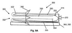
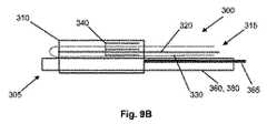
さらに図1Aを参照すると、肥満療法を提供するための(システム(100)はさらに、実施形態において、胃腸内埋め込み装置(105)を埋め込みの部位に送達するための送達機構(115)を含む。実施形態において、送達機構(115)は、送出端(112)、対向する端部(114)、およびそれらの間に通路(116)を有するハウジング(110)を含むことができる。1つの実施形態では、送出端(112)は、装置(105)のスリーブ(130)が送達機構(115)へと挿入される(例えば、内転された位置で)のを可能にするように設計することができる。さらに、送出端(112)の大きさは、係留機構(140)が送出端(112)のまわりに確実に位置付けられることを可能にするのに十分な大きさであり得る。 Still referring to FIG. 1A, the system (100) for providing obesity therapy further includes, in embodiments, a delivery mechanism (115) for delivering the gastrointestinal implant device (105) to the site of implantation. In an embodiment, the delivery mechanism (115) can include a housing (110) having a delivery end (112), an opposing end (114), and a passageway (116) therebetween. Then, the delivery end (112) may be designed to allow the sleeve (130) of the device (105) to be inserted into the delivery mechanism (115) (eg, in an inward position). Further, the size of the delivery end (112) may be large enough to allow the anchoring mechanism (140) to be securely positioned about the delivery end (112). .
1つの実施形態では、ハウジング(110)は、腸管を通り抜け、装置(105)を埋め込みの部位へと送達することができる任意の材料から作ることができる。そのために、ハウジング(110)は、送達間にハウジング(110)の変形を最小限にするように、略硬質な材料から形成され得る。略硬質である材料の例は、金属、プラスチック、セラミックス、または略一貫した形状を維持することができる任意の他の材料を含む。ハウジング(110)は、ハウジング(110)の圧縮を可能にするために、十分に可撓性である材料から作られ得る。例えば、ハウジング(110)は、ポリウレタンによってラミネートされたナイロンなどの、薄い壁で囲まれた膜から形成され得る。 In one embodiment, the housing (110) can be made from any material that can pass through the intestine and deliver the device (105) to the site of implantation. To that end, the housing (110) can be formed from a substantially rigid material so as to minimize deformation of the housing (110) during delivery. Examples of materials that are substantially rigid include metals, plastics, ceramics, or any other material that can maintain a substantially consistent shape. The housing (110) can be made from a material that is sufficiently flexible to allow compression of the housing (110). For example, the housing (110) may be formed from a thin walled membrane, such as nylon laminated with polyurethane.
ハウジング(110)は、ヒトまたは動物の身体の腸管へと挿入されるように設計されているため、実施形態において、生体適合性のある材料から作ることができる。材料の生体適合性は、腸管内のハウジング(110)の使用が原因である有害反応の発生を最小限にする助けとなり得る。ハウジング(110)はさらに、腸管への挿入後に、ハウジング(110)と腸壁との間の摩擦を減少させるために、外側表面上にコーティング剤を含み得る。同様に、ハウジング(110)は、ハウジング(110)内に位置するスリーブ(130)の展開の間に摩擦を減少させるために、内部表面上にコーティング剤を含み得る。 Since the housing (110) is designed to be inserted into the intestinal tract of the human or animal body, in embodiments it can be made from a biocompatible material. The biocompatibility of the material can help minimize the occurrence of adverse reactions due to the use of the intestinal housing (110). The housing (110) may further include a coating on the outer surface to reduce friction between the housing (110) and the intestinal wall after insertion into the intestinal tract. Similarly, the housing (110) can include a coating on the internal surface to reduce friction during deployment of the sleeve (130) located within the housing (110).
ハウジング(110)の形状が、埋め込みのための部位に装置(105)を送達するハウジング(110)の能力に影響を与え得るため、ハウジング(110)には、特定用途に依存して、望ましい任意の形状が設けられ得ることを認識されたい。例えば、ハウジング(110)は、管状の形状であってもよい。ハウジング(110)は、他の実施形態において、三角形の形状であってもよい。もちろん、本発明が、このように限定するようには意図されていないため、他の形状も使用することができる。 Since the shape of the housing (110) can affect the ability of the housing (110) to deliver the device (105) to the site for implantation, the housing (110) may have any desired, depending on the particular application. It should be appreciated that other shapes may be provided. For example, the housing (110) may have a tubular shape. The housing (110) may have a triangular shape in other embodiments. Of course, other shapes can be used as the invention is not intended to be so limited.
送達機構(115)はまた、図1Aで示されるように、装置(105)のスリーブ(130)を、ハウジング(110)内から埋め込みの部位(例えば、胃及び/又は小腸)へと進めることに使用されるための展開するバルーン(120)を含むことができる。展開するバルーン(120)は、実施形態において、開放端(122)および閉鎖端(124)を含み得、スリーブ(130)を収容するのに十分な長さを提供され得る。実施形態において、展開するバルーン(120)の開放端(122)には、ハウジング(110)の送出端(112)を有するぴったりフィットしたシールが設けられ得る。ハウジング(110)の送出端(112)でそのようなシールを提供することによって、および展開するバルーン(120)に閉鎖端(124)を提供することによって、正圧が、ハウジング(110)へと導入され得、ハウジング(110)内から、展開するバルーン(120)を外転させ、展開するバルーン(120)からのスリーブ(130)の展開を助ける。もちろん、展開するバルーン(120)およびハウジング(110)は、互いに(例えば、ワンピースの(one−piece design)設計として)一体化することができ、ここで、追加のシールは、ハウジング(110)において正圧を維持するために必要でないかもしれない。 The delivery mechanism (115) also advances the sleeve (130) of the device (105) from within the housing (110) to the implantation site (eg, stomach and / or small intestine), as shown in FIG. 1A. A deploying balloon (120) for use may be included. The deploying balloon (120), in embodiments, can include an open end (122) and a closed end (124) and can be provided with a length sufficient to accommodate the sleeve (130). In embodiments, the open end (122) of the deploying balloon (120) may be provided with a snug fit seal having the delivery end (112) of the housing (110). By providing such a seal at the delivery end (112) of the housing (110) and by providing a closed end (124) on the deploying balloon (120), positive pressure is applied to the housing (110). Can be introduced to ablate the deploying balloon (120) from within the housing (110) and assist in deploying the sleeve (130) from the deploying balloon (120). Of course, the deploying balloon (120) and the housing (110) can be integrated with each other (eg, as a one-piece design), where an additional seal is in the housing (110). It may not be necessary to maintain positive pressure.
埋め込みの部位に装置(105)を展開するために、展開するバルーン(120)は、展開するバルーン(120)の外転、およびそれ故、ハウジング(110)内からのスリーブ(130)の促進が可能となるように、十分な力に抵抗することができる材料から作ることができる。実施形態において、展開するバルーン(120)は、薄い壁で囲まれた膜から作られ得る。例えば、展開するバルーン(120)は、ポリウレタンまたは任意の類似した材料によってラミネートされたナイロンから作られ得る。実施形態において、展開するバルーン(120)は、約0.05mm乃至約0.09mmの範囲の厚さを有し得る。実施形態において、展開するバルーン(120)の厚さは、約0.076mmまたは0.003インチであり得る。展開するバルーン(120)の材料はまた、展開するバルーン(120)が十分な正圧に抵抗することを可能にするために、流体に対して不浸透性であり得る。展開するバルーン(120)が、ヒトまたは動物の身体の腸管内に挿入されるように設計されているため、展開するバルーン(120)は、生体適合性のある材料から作ることができる。材料の生体適合性は、腸管内の展開するバルーン(120)の使用が原因である有害反応の発生を最小限にする助けとなり得る。 In order to deploy the device (105) at the site of implantation, the deploying balloon (120) is able to ablate the deploying balloon (120) and thus promote the sleeve (130) from within the housing (110). It can be made from a material that can resist sufficient forces, as possible. In embodiments, the deploying balloon (120) can be made from a thin walled membrane. For example, the deploying balloon (120) can be made from nylon laminated with polyurethane or any similar material. In embodiments, the deploying balloon (120) can have a thickness in the range of about 0.05 mm to about 0.09 mm. In embodiments, the thickness of the deployed balloon (120) can be about 0.076 mm or 0.003 inches. The material of the deploying balloon (120) can also be impermeable to the fluid to allow the deploying balloon (120) to resist sufficient positive pressure. Since the deploying balloon (120) is designed to be inserted into the intestinal tract of the human or animal body, the deploying balloon (120) can be made from a biocompatible material. The biocompatibility of the material can help to minimize the occurrence of adverse reactions due to the use of a deploying balloon (120) in the intestinal tract.
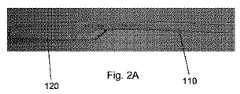
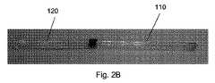
図2A−2Bで示されるように、ハウジング(110)および展開するバルーン(120)は、互いに一体化することができるか(図2A)、または2つの分離した構成要素として提供され得る(図2B)。ハウジング(110)および展開するバルーン(120)が互いに一体化することができる実施形態では、ハウジング(110)および展開するバルーン(120)は、同じ材料、例えば、同じ、十分に可撓性である材料の長尺シートで作ることができる。このように、ハウジング(110)および展開するバルーン(120)のために、取付機構または結合機構は必要とされない。適切な材料は、限定しないが、プラスチック、ゴム、ポリマー、樹脂、布(cloth)などを含む。あるいは、ハウジング(110)および展開するバルーン(120)が2つの分離した構成要素であることができる実施形態では、ハウジング(110)および展開するバルーン(120)は、異なる材料で作ることができる。例えば、ハウジング(110)は、十分に剛性な材料で作ることができる一方で、展開するバルーン(120)は、十分に可撓性である材料で作ることができる。もちろん、ハウジング(110)および展開するバルーン(120)の両方のために、同じ材料を使用することができる。当該技術分野で既知の取付機構または結合機構も、ハウジング(110)と展開するバルーン(120)を接続するように、所望される程度まで提供され得る。 As shown in FIGS. 2A-2B, the housing (110) and the deploying balloon (120) can be integrated with each other (FIG. 2A) or provided as two separate components (FIG. 2B). ). In embodiments where the housing (110) and the deploying balloon (120) can be integrated with each other, the housing (110) and the deploying balloon (120) are the same material, eg, the same, sufficiently flexible. Can be made from a long sheet of material. Thus, no attachment or coupling mechanism is required for the housing (110) and the deploying balloon (120). Suitable materials include but are not limited to plastics, rubbers, polymers, resins, cloths and the like. Alternatively, in embodiments where the housing (110) and deploying balloon (120) can be two separate components, the housing (110) and deploying balloon (120) can be made of different materials. For example, the housing (110) can be made of a sufficiently rigid material, while the deploying balloon (120) can be made of a sufficiently flexible material. Of course, the same material can be used for both the housing (110) and the deploying balloon (120). Attachment or coupling mechanisms known in the art can also be provided to the desired extent to connect the housing (110) and the deploying balloon (120).
図2Aで示されるように、ハウジング(110)は、展開するバルーン(120)の直径よりも実質的に小さな直径を有することができる。一例では、ハウジング(110)の直径は、展開するバルーン(120)の約半分であり得るが、それでも展開するバルーン(120)を収容することができる。他の例(例えば、図2B)において、ハウジング(110)は、展開するバルーン(120)の直径よりも大きな直径を有することができる。図2A−2Bが、その外転されたまたは展開された位置で展開するバルーン(120)を例証し、外転または展開の前に、展開するバルーン(120)が、ハウジング(110)内の展開のために内転され得ることを留意されたい。もちろん、ハウジング(110)および展開するバルーン(120)の直径は、全体にわたって略一定のままであり得る。 As shown in FIG. 2A, the housing (110) can have a diameter that is substantially smaller than the diameter of the deploying balloon (120). In one example, the diameter of the housing (110) can be about half that of the deploying balloon (120), but can still accommodate the deploying balloon (120). In other examples (eg, FIG. 2B), the housing (110) can have a diameter that is larger than the diameter of the balloon (120) that is deployed. FIGS. 2A-2B illustrate a balloon (120) that deploys in its abducted or deployed position, and prior to abduction or deployment, the deploying balloon (120) is deployed in the housing (110). Note that it can be introverted for. Of course, the diameter of the housing (110) and deploying balloon (120) may remain substantially constant throughout.
展開するバルーン(120)の大きさに対するハウジング(110)の大きさにかかわらず、各々の直径が、スリーブ(130)を収容するのに十分であるべきことを認識されたい。ハウジング(110)の長さは、送達機構(115)が腸管へと挿入され、腸管に沿って埋め込みのための部位に進められることを可能にするべきであることを認識されたい。 It should be appreciated that each diameter should be sufficient to accommodate the sleeve (130) regardless of the size of the housing (110) relative to the size of the balloon (120) to be deployed. It should be appreciated that the length of the housing (110) should allow the delivery mechanism (115) to be inserted into the intestinal tract and advanced along the intestinal tract to a site for implantation.
ハウジング(110)は、実施形態において、ハウジング(110)の形状が、埋め込みのための部位への装置(105)の送達を促進することができるため、特定用途に依存して、望ましい任意の形状を有し得る。例えば、ハウジング(110)は、管状の形状であってもよい。もちろん、本発明が、このように限定するようには意図されていないため、他の形状も使用することができる。 The housing (110), in embodiments, can be any shape desired depending on the particular application, since the shape of the housing (110) can facilitate delivery of the device (105) to the site for implantation. Can have. For example, the housing (110) may have a tubular shape. Of course, other shapes can be used as the invention is not intended to be so limited.
1つの実施形態によると、送達機構(115)はさらに、ハウジング(110)内からの展開するバルーン(120)の外転を引き起こすように、ハウジング(110)へ正圧を導入するための膨張機構(図4に示される膨張装置(250)など)を含むことができる。適切な膨張機構は、例えば、膨張カテーテル、ポンプ、またはハウジング(110)に正圧を導入することができる任意の他の膨張装置を含むことができる。膨張機構は、ハウジング(110)に分離可能に連結され得るため、膨張後に、ハウジング(110)から取り外され得る且つ切り離され得る。ハウジング(110)との膨張機構の接続は、当技術分野で既知の任意の方法を使用して達成され得る。 According to one embodiment, the delivery mechanism (115) further includes an inflation mechanism for introducing positive pressure into the housing (110) to cause abduction of the deploying balloon (120) from within the housing (110). (Such as the inflator (250) shown in FIG. 4). Suitable inflation mechanisms can include, for example, an inflation catheter, pump, or any other inflation device that can introduce positive pressure into the housing (110). The expansion mechanism can be detachably coupled to the housing (110) so that it can be detached from the housing (110) and disconnected after expansion. The connection of the expansion mechanism with the housing (110) may be accomplished using any method known in the art.
膨張式の機構の使用を介してハウジング(110)へと正圧を導入するために、本発明のシステム(100)には、ハウジング(110)に膨張ポート(170)が提供され得、それを通って、流体(例えば、空気、液体、ガスまたは他の物質)は、展開するバルーン(120)を外転させ、続いて胃腸内埋め込み装置(105)を展開するために、十分な正圧を有して入ることができる。1つの実施形態において、膨張ポート(170)は、ハウジング(110)の端部(114)に位置することができる。もちろん、流体が、装置(105)を展開するために、十分な力を有して入ることができる限り、膨張ポート(170)のための他の位置も可能であり得る。 In order to introduce positive pressure into the housing (110) through the use of an inflatable mechanism, the system (100) of the present invention may be provided with an expansion port (170) in the housing (110). Through the fluid (eg, air, liquid, gas or other substance), sufficient positive pressure is applied to ablate the deploying balloon (120) and subsequently deploy the gastrointestinal implant device (105). You can enter. In one embodiment, the inflation port (170) can be located at the end (114) of the housing (110). Of course, other locations for the inflation port (170) may be possible as long as the fluid can enter with sufficient force to deploy the device (105).
ここで図3A−3Bを参照すると、本発明のシステム(100)は、胃鏡(160)、(160’)に関連して使用することができる。胃鏡(160)、(160’)は、胃腸管を通ってシステム(100)を誘導する助けとなり得る。実施形態において、図3Aでの胃鏡(160)には、ハウジング(110)のまわりに又はそれに隣接して位置するように設計された本体が設けられ得る。胃鏡(160)にはまた、係留機構(140)の表面に対して位置付けられる先端(162)が設けられ得る。このような実施形態において、係留機構(140)は、図3Aで示されるように、胃鏡(160)の端部からの視覚化を可能にするために、透明材料から構成され得る。本発明の胃腸内埋め込み装置(105)の展開を助けるために、X線の曝露または他の機構は必要とされないかもしれない。所望されるのであれば、送達機構(115)および装置(105)は、埋め込みの間にユーザーによる視覚化を可能にするために、不透明な物質を含み得る。 Referring now to FIGS. 3A-3B, the system (100) of the present invention can be used in connection with gastroscopes (160), (160 '). Gastroscopes (160), (160 ') may help guide system (100) through the gastrointestinal tract. In an embodiment, the gastroscope (160) in FIG. 3A may be provided with a body designed to be located around or adjacent to the housing (110). The gastroscope (160) may also be provided with a tip (162) positioned relative to the surface of the anchoring mechanism (140). In such embodiments, the anchoring mechanism (140) may be constructed from a transparent material to allow visualization from the end of the gastroscope (160), as shown in FIG. 3A. To assist in the deployment of the gastrointestinal implant device (105) of the present invention, X-ray exposure or other mechanisms may not be required. If desired, the delivery mechanism (115) and device (105) may include opaque materials to allow visualization by the user during implantation.
特定の実施形態では、本発明のシステム(100)は、胃鏡(160’)が、胃管を通ってシステム(100)を誘導する助けとなることが可能となるように設計され得る。図3Bで示されるように、胃鏡(160’)は、その外転された又は展開された位置で、展開するバルーン(120’)およびスリーブ(130’)とともに使用され得、スリーブ(130’)を、その所望の位置に誘導する助けとなる(例えば、小腸に沿ってさらに伸びる)。胃鏡(160’)は、示されるように、ハウジング(110)を介して(超えて(beyond))位置付けられ得、システム(100)が胃腸管に沿って進められるために、システム(100)の安定性を維持するように設計され得る。胃鏡(160)が、システム(100)の誘導を可能にする任意の方法で位置付けられ得る一方で、その設計は、外転からの展開するバルーン(120)およびスリーブ(130)の障害を最小限にするべきことを留意されたい。実施形態において、胃鏡(160)は、市販で入手可能である任意のガイドワイヤーであってもよい。 In certain embodiments, the system (100) of the present invention may be designed to allow a gastroscope (160 ') to help guide the system (100) through a gastric tube. As shown in FIG. 3B, the gastroscope (160 ′) may be used with a deploying balloon (120 ′) and sleeve (130 ′) in its abducted or deployed position, the sleeve (130 ′) Helps guide it to its desired location (eg, extends further along the small intestine). The gastroscope (160 ′) can be positioned through the housing (110), as shown, so that the system (100) can be advanced along the gastrointestinal tract of the system (100). It can be designed to maintain stability. While the gastroscope (160) can be positioned in any way that allows guidance of the system (100), its design minimizes obstruction of the deploying balloon (120) and sleeve (130) from abduction. Please note that In embodiments, the gastroscope (160) may be any commercially available guidewire.
ここで図4−6を参照すると、本発明の代替システムが例証される。例証されるように、システム(200)は、肥満療法を提供するために使用することができる。システム(200)は、実施形態において、送達機構(215)および埋め込み装置(205)を含むことができる。図4−6で示される実施形態によると、送達機構(215)は、上に記載される送達機構(115)と略類似し得るが、ハウジング(110)の送達機構(215)は、装置(205)の展開に関連して使用するためのリザーバー(210)であり得る。そのようなハウジング(210)は、腸管へと挿入されることに加えて、送達機構(215)が、患者における胃などの、異なる臓器に残ることを可能にする。送達機構(215)は、1つの実施形態によると、装置(205)の埋め込みに関連して使用するためのリザーバー(210)を含み得る。1つの実施形態では、リザーバー(210)は、装置(205)の少なくとも一部分を収容し、埋め込みのための部位に装置(205)を送達するために使用され得る点で、ハウジング(110)と略同じ機能を果たし得る。リザーバー(210)は、所望されるのであれば、リザーバー(210)にスリーブ(230)を収容するように設計され得、スリーブ(230)の外転を促進するように設計され得る。 Referring now to FIGS. 4-6, an alternative system of the present invention is illustrated. As illustrated, system (200) can be used to provide obesity therapy. The system (200) can, in embodiments, include a delivery mechanism (215) and an implant device (205). According to the embodiment shown in FIGS. 4-6, the delivery mechanism (215) may be generally similar to the delivery mechanism (115) described above, but the delivery mechanism (215) of the housing (110) 205) can be a reservoir (210) for use in connection with deployment. Such a housing (210), in addition to being inserted into the intestine, allows the delivery mechanism (215) to remain in a different organ, such as the stomach in a patient. The delivery mechanism (215) may include a reservoir (210) for use in connection with implantation of the device (205), according to one embodiment. In one embodiment, reservoir (210) houses at least a portion of device (205) and is generally abbreviated as housing (110) in that it can be used to deliver device (205) to a site for implantation. Can perform the same function. Reservoir (210) can be designed to accommodate sleeve (230) in reservoir (210), if desired, and can be designed to facilitate abduction of sleeve (230).
実施形態において、リザーバー(210)は、破裂することなく、患者の身体内に配向されることが可能となるのに十分強い物質から作ることができる。物質はまた、実施形態において、リザーバー(210)が、装置(205)の展開の間に拡張し、折り畳まることが可能となるように、十分可撓性であり得る。 In embodiments, the reservoir (210) can be made from a material that is strong enough to be able to be oriented within the patient's body without rupturing. The material can also be sufficiently flexible in embodiments to allow the reservoir (210) to expand and collapse during deployment of the device (205).
リザーバー(210)は、その形状が送達のために腸管または食道内に適合することができる限り、任意の形状を有し得る。実施形態において、リザーバー(210)は、略環状の形状であり得、所望される任意の形状に拡張することができる。別の実施形態では、リザーバー(210)は、管状の形状であり得る。もちろん、他の形状も可能である。リザーバー(210)は、別の実施形態において、バルーン(220)及び/又はスリーブ(230)を収容するのに十分な大きさ及び/又は長さを有し得る。図5Aで示されるように、リザーバー(210)の大きさ及び/又は長さは、折り重ねた又は巻き上げた方法で、バルーン(220)及び/又はスリーブ(230)を収容し得るような大きさ及び/又は長さであり得る。 Reservoir (210) can have any shape as long as its shape can fit within the intestine or esophagus for delivery. In embodiments, the reservoir (210) can be generally annular in shape and can be expanded to any desired shape. In another embodiment, the reservoir (210) can be tubular in shape. Of course, other shapes are possible. The reservoir (210) may have a size and / or length sufficient to accommodate the balloon (220) and / or the sleeve (230) in another embodiment. As shown in FIG. 5A, the size and / or length of the reservoir (210) is sized to accommodate the balloon (220) and / or sleeve (230) in a folded or rolled manner. And / or length.
リザーバー(210)の大きさが、装置(205)およびスリーブ(230)の送達を促進し得るため、リザーバー(210)にはまた、望ましい任意の大きさが提供され得る。例えば、より小さな大きさのリザーバー(210)は、個体の食道を通って装置(205)を送達ために使用され得る一方で、より大きな大きさのリザーバー(210)は、食道を通って適合することができないかもしれない。 Since the size of the reservoir (210) can facilitate delivery of the device (205) and sleeve (230), the reservoir (210) can also be provided with any desired size. For example, a smaller sized reservoir (210) may be used to deliver the device (205) through the individual's esophagus, while a larger sized reservoir (210) fits through the esophagus. It may not be possible.
送達機構(215)はさらに、実施形態において、胃腸管内の埋め込みの部位で装置(205)の展開に使用するための、展開するバルーン(120)に類似した、展開するバルーン(220)を含み得る。
展開するバルーン(220)の長さおよび形状は、バルーン(220)が、(例えば、折り重ねた又は巻き上げた方法で)リザーバー(210)内で少なくとも部分的に適合することができるような長さおよび形状であるべきことを留意されたい。実施形態において、バルーン(220)は、その開放端(222)でリザーバー(210)の端部のまわりに付けられ得るか又は位置付けられ得る。Delivery mechanism (215) may further include a deploying balloon (220), similar to deploying balloon (120), in embodiments, for use in deploying device (205) at the site of implantation in the gastrointestinal tract. .
The length and shape of the deployed balloon (220) is such that the balloon (220) can be at least partially adapted within the reservoir (210) (eg, in a folded or rolled manner). Note that and should be in shape. In embodiments, the balloon (220) can be attached or positioned around the end of the reservoir (210) at its open end (222).
スリーブ(230)はまた、上に記載されるように、スリーブ(130)が、展開するバルーン(120)およびハウジング(110)内に保存され得る方法に類似した方法で、展開するバルーン(220)内に保存され得る(例えば、内転された状態で)。実施形態において、スリーブ(230)は、図5Aで示されるような折り畳み状態で保存され得るか、または巻き上げ状態で保存され得る。もちろん、スリーブ(230)は、リザーバー(210)内で少なくとも部分的に適合する限り、他の方法で保存され得る。埋め込みの部位に対する係留装置および固定装置(205)のための係留機構(240)は、図4に示されるように、上に記載されたものに類似して、スリーブ(230)の近位端(232)で位置し得る。 The sleeve (230) may also be deployed in a manner similar to the manner in which the sleeve (130) can be stored in the deploying balloon (120) and the housing (110), as described above. Can be stored within (eg, in adducted state). In embodiments, the sleeve (230) can be stored in a folded state as shown in FIG. 5A or can be stored in a rolled up state. Of course, the sleeve (230) may be stored in other ways as long as it fits at least partially within the reservoir (210). The anchoring mechanism (240) for the anchoring device and anchoring device (205) for the site of implantation is similar to that described above, as shown in FIG. 232).
胃腸内埋め込み装置(205)を展開するために、膨張装置(250)は、リザーバー(210)に連結され得る。膨張装置(250)は、実施形態において、患者の食道を通って胃腸内埋め込み装置(205)の挿入を可能にするように設計され得る。実施形態において、膨張装置(250)は、十分に薄く且つ狭くなり得る。シール(280)は、膨張装置(250)によって導入されている流体の漏出を最小限にするために、所望されるように、膨張装置(250)の端部で提供され得る。 In order to deploy the gastrointestinal implant device (205), the inflation device (250) can be coupled to the reservoir (210). The inflation device (250), in embodiments, may be designed to allow insertion of the gastrointestinal implant device (205) through the patient's esophagus. In embodiments, the expansion device (250) can be sufficiently thin and narrow. A seal (280) may be provided at the end of the expansion device (250) as desired to minimize leakage of fluid being introduced by the expansion device (250).
図5A、5Bおよび6は、システム(200)を、胃管(200)を通って対象の部位に誘導するのを助けるための胃鏡(260)の使用を示す。胃鏡(260)は、図5Aで示されるように、膨張装置(250)およびリザーバー(210)を介して位置付けることができる。図6に示される別の実施形態では、胃鏡(260’)は、膨張装置(250)を通り抜けることなく、リザーバー(210)まで伸びることができる。図5Bおよび6が、展開するバルーン(220’)およびスリーブ(230’)をそれらの外転された位置で有する、十分に展開された状態で、システム(200’)を示すことを留意されたい。 5A, 5B and 6 illustrate the use of a gastroscope (260) to help guide the system (200) through the gastric tube (200) to the site of interest. The gastroscope (260) can be positioned through the inflation device (250) and reservoir (210), as shown in FIG. 5A. In another embodiment shown in FIG. 6, the gastroscope (260 ') can extend to the reservoir (210) without passing through the inflation device (250). Note that FIGS. 5B and 6 show the system (200 ′) in a fully deployed state with the deploying balloon (220 ′) and sleeve (230 ′) in their abducted position. .
身体への挿入のためにシステム(100)を準備するために、ユーザーは、最初に、送達機構(115)のハウジング(110)内に展開するバルーン(120)を位置付けることができる。1つの実施形態では、展開するバルーン(120)の開放端(122)は、ハウジング(110)の送出端(112)に隣接して位置し得るか又はその送出端(112)に付けられ得、展開するバルーン(120)の閉鎖端(124)は、ハウジング(110)の対向する端部(114)に隣接して位置し得る。端部が開口したスリーブ(130)は、その後、展開するバルーン(120)の閉鎖端(124)に隣接して位置するスリーブ(130)の端部が開口した遠心端(134)とともに、展開するバルーン(120)の空洞(126)内に置かれ得る一方で、スリーブ(130)の近位端(132)は、展開するバルーン(120)の開放端(122)に隣接して位置し得る。さらに、スリーブ(130)の近位端(132)に連結されている、係留機構(140)は、ハウジング(110)の送出端(112)のまわりに位置付けられ得る。 To prepare the system (100) for insertion into the body, a user can first position the balloon (120) that deploys within the housing (110) of the delivery mechanism (115). In one embodiment, the open end (122) of the deploying balloon (120) can be located adjacent to or attached to the delivery end (112) of the housing (110), The closed end (124) of the deploying balloon (120) may be located adjacent the opposing end (114) of the housing (110). The open end sleeve (130) is then deployed with the distal end (134) of the sleeve (130) open adjacent the closed end (124) of the deploying balloon (120). The proximal end (132) of the sleeve (130) may be located adjacent to the open end (122) of the deploying balloon (120) while it may be placed within the cavity (126) of the balloon (120). Further, an anchoring mechanism (140) coupled to the proximal end (132) of the sleeve (130) can be positioned around the delivery end (112) of the housing (110).
システム(100)は、一旦設置されると、身体へ挿入され得、身体内の腸管に沿って埋め込みのための対象の部位に進められ得る。胃鏡(160)は、システム(100)を、胃管を通って埋め込みの部位に誘導するのを助けるために使用され得る。実施形態において、ガイドワイヤー(図示せず)は、システム(100)が管を通って進むと、システム(100)の安定性を維持するために使用され得る。埋め込みの部位で1回、システム(100)は、装置(105)を展開するために準備することができる。埋め込みには、最初、スリーブ(130)の近位端(132)へ付けられた、係留機構(140)が、膨張機構を使用して膨張される必要があり得る。係留機構(140)の膨張は、外転プロセスの間に、所望位置で胃腸内埋め込み装置(105)を保持するために作用することができる。例えば、係留機構(140)は、胃内に、または幽門接合部に隣接する小腸に置くことができる。係留機構(140)が対象の部位で係留された後に、スリーブ(130)は外転され得る。外転には、加圧された又は加圧されなかった流体(例えば、ガス、液体、またはその組み合わせ)が、膨張ポート(170)経由でハウジング(110)へと配向される必要があり得る。液体は、図3Bで示されるように、ハウジング(110)へと配向されると、ハウジング(110)内からの展開するバルーン(120)を外転させる且つ進めるために作用する一方で、展開するバルーン(120)とともに、ハウジング(110)からスリーブ(130)を押す。幾つかの実施形態では、スリーブ(130)は、展開するバルーン(120)より短い長さであり、これによって、展開するバルーン(120)の十分な外転後に、スリーブ(130)の完全な送達が可能となる。 Once installed, the system (100) can be inserted into the body and advanced along the intestinal tract within the body to the site of interest for implantation. The gastroscope (160) can be used to help guide the system (100) through the gastric tube to the site of implantation. In an embodiment, a guide wire (not shown) may be used to maintain the stability of the system (100) as the system (100) is advanced through the tube. Once at the site of implantation, the system (100) can be prepared to deploy the device (105). For implantation, the anchoring mechanism (140) initially attached to the proximal end (132) of the sleeve (130) may need to be inflated using an inflation mechanism. The expansion of the anchoring mechanism (140) can act to hold the gastrointestinal implant device (105) in the desired position during the abduction process. For example, the anchoring mechanism (140) can be placed in the stomach or in the small intestine adjacent to the pyloric junction. After the anchoring mechanism (140) is anchored at the site of interest, the sleeve (130) can be abducted. Abduction may require pressurized or unpressurized fluid (eg, gas, liquid, or a combination thereof) to be directed to the housing (110) via the expansion port (170). When the liquid is oriented into the housing (110), as shown in FIG. 3B, the liquid expands while acting to ablate and advance the deploying balloon (120) from within the housing (110). The sleeve (130) is pushed from the housing (110) together with the balloon (120). In some embodiments, the sleeve (130) is shorter in length than the deploying balloon (120), so that after full abduction of the deploying balloon (120), complete delivery of the sleeve (130). Is possible.
図7−8は、部分的な外転および十分な外転後の続く展開におけるシステム(100)の展開するバルーン(120)およびスリーブ(130)を示す。図7では、胃腸内埋め込み装置(105’)は、ハウジング(110)の通路(116)内から外転されているプロセスにあり、ここで、展開するバルーン(120’)を外転することで、その内部からスリーブ(130’)を押し、外転させる。外転する展開するバルーン(120’)は、その後、外転するスリーブ(130’)を展開しているため腸管を膨張することができ、自動的に腸の進路に従うことができる。図8は、十分に展開された状態での埋め込み装置(105”)示し、外転された展開するバルーン(120”)は、外転されたスリーブ(130”)を越えて伸びる。腸壁内に展開され、係合された胃腸内埋め込み装置(105”)によって、食物および他の食品材料は、胃から、外転されたスリーブ(130”)を通って渡され得る。 FIGS. 7-8 show the deploying balloon (120) and sleeve (130) of the system (100) in partial deployment and subsequent deployment after full abduction. In FIG. 7, the gastrointestinal implant device (105 ′) is in the process of being abducted from within the passageway (116) of the housing (110), where the ablating balloon (120 ′) is ablated. Then, the sleeve (130 ′) is pushed from the inside to rotate. The deploying balloon (120 ') that abducts can then inflate the intestinal tract because it deploys the abducting sleeve (130') and can automatically follow the course of the intestine. 8 shows the implant device (105 ″) in a fully deployed state, with the abducted deployed balloon (120 ″) extending beyond the abducted sleeve (130 ″). With the gastrointestinal implant device (105 ") deployed and engaged, food and other food materials can be passed from the stomach through the abducted sleeve (130").
図4−6で描写される実施形態によると、リザーバー(210)を使用して装置(205)を展開する方法は、上に記載された方法と略類似し得、リザーバー(210)の使用を反映するためのいくつかの変更を有する。システム(200)は、一旦リザーバー(210)に設置されると、身体へと挿入され得、身体内の腸管に沿って埋め込みの部位に進められ得る。胃鏡(260)は、胃腸管を通ってシステム(200)を誘導するために使用され得る。埋め込みには、最初、スリーブ(230)の近位端(232)へ付けられた、係留機構(140)が、膨張機構を使用して膨張される必要があり得る。係留機構(240)が埋め込みの部位で胃または小腸に係留された後、装置(205)は外転され得る。図5Aに示されるように、外転には、膨張装置(250)の起動が必要とされ得、これによって結果的に、リザーバー(210)は膨張される。リザーバー(210)の膨張によって、リザーバー(210)は拡大する及び/又は加圧され得、バルーン(220)が装置(205)を外転させ、展開することを可能にする。図5Bおよび6は、十分に展開された状態でのシステム(200)の実施形態を示す。実施形態において、リザーバー(210)は、バルーン(220)およびスリーブ(230)を外転するための低摩擦のコンパートメントを提供することができる。 According to the embodiment depicted in FIGS. 4-6, the method of deploying the device (205) using the reservoir (210) can be substantially similar to the method described above, and the use of the reservoir (210) Has some changes to reflect. Once installed in the reservoir (210), the system (200) can be inserted into the body and advanced along the intestinal tract within the body to the site of implantation. The gastroscope (260) may be used to guide the system (200) through the gastrointestinal tract. For implantation, the anchoring mechanism (140) initially attached to the proximal end (232) of the sleeve (230) may need to be inflated using an inflation mechanism. After anchoring mechanism (240) is anchored to the stomach or small intestine at the site of implantation, device (205) can be abducted. As shown in FIG. 5A, abduction may require activation of the expansion device (250), which results in expansion of the reservoir (210). By expansion of the reservoir (210), the reservoir (210) can expand and / or be pressurized, allowing the balloon (220) to ablate and deploy the device (205). 5B and 6 show an embodiment of the system (200) in a fully deployed state. In an embodiment, the reservoir (210) can provide a low friction compartment for abduction of the balloon (220) and sleeve (230).
スリーブ(130)の展開後、展開するバルーン(120)は収縮され得、展開するバルーン(120)を圧縮(constrict)するために、真空が引かれ得る。展開するバルーン(120)の圧縮によって、展開するバルーン(120)は、スリーブ(130)から引き出されることが可能であり、スリーブ(130)を腸管内の位置に残す。展開するバルーン(120)の直径が、スリーブ(130)の直径未満になり得るため、展開するバルーン(120)の引き出しは、展開するバルーン(120)における収縮および真空の形成後に行われる。以前に述べられたように、コーティング剤または潤滑剤は、製造中にスリーブ(130)と展開するバルーン(120)との間に入れられ得、容易な展開するバルーン(120)の除去を確かなものとする。 After deployment of the sleeve (130), the deploying balloon (120) can be deflated and a vacuum can be drawn to compress the deploying balloon (120). By compressing the deploying balloon (120), the deploying balloon (120) can be withdrawn from the sleeve (130), leaving the sleeve (130) in position within the intestinal tract. Because the diameter of the deploying balloon (120) can be less than the diameter of the sleeve (130), the withdrawal of the deploying balloon (120) occurs after deflation and the creation of a vacuum in the deploying balloon (120). As previously stated, a coating or lubricant can be placed between the sleeve (130) and the deploying balloon (120) during manufacture to ensure easy removal of the deploying balloon (120). Shall.
ここで図9−13を参照すると、本発明の実施形態による、別の肥満療法システム(300)が示される。システム(300)は、実施形態において、送達機構(315)および埋め込み装置(305)を含むことができる。図9−13で示されるように、送達機構(315)は、上に記載される送達機構(115)、(215)に略類似し得るが、装置(305)を展開するのに別々のハウジングは必要とされないかもしれない。送達機構(315)は、実施形態において、胃腸管内の埋め込みの部位で装置(305)の展開に使用するために、上に記載される実施形態において、展開するバルーン(120)およびハウジング(110)に類似した、展開するバルーン(320)を含み得る。展開するバルーン(320)の長さおよび形状は、バルーン(320)が腸管内に適合することができるような長さおよび形状であるべきことを留意されたい。実施形態において、展開するバルーン(320)は、図9Aで示されるように、一続きの(continuous)1つの材料から形成され得る。展開するバルーン(320)はまた、柔らかい且つ可撓性である材料から形成され得、その結果、バルーン(320)の膨張後に、その中の圧力によって、装置(305)は、腸管を通って進められることが可能となる。展開するバルーン(320)が作られ得る材料はまた、装置(305)を展開するのに十分な圧力に抵抗するために、非弾性であり得る。実施形態において、展開するバルーン(320)は、単一の薄い壁で囲まれた膜から形成され得る。例えば、展開するバルーン(320)は、ポリウレタンによってラミネートされたナイロンから作られ得る。実施形態において、展開するバルーン(320)は、約0.05mmから約0.09mmの範囲の厚さを有し得る。実施形態において、展開するバルーン(320)の厚さは、約0.076mmまたは0.003インチであり得る。 Referring now to FIGS. 9-13, another obesity therapy system (300) is shown according to an embodiment of the present invention. The system (300) can, in embodiments, include a delivery mechanism (315) and an implant device (305). As shown in FIGS. 9-13, the delivery mechanism (315) can be generally similar to the delivery mechanisms (115), (215) described above, but with a separate housing to deploy the device (305). May not be needed. The delivery mechanism (315), in embodiments, is deployed in the embodiment described above for use in deploying the device (305) at the site of implantation in the gastrointestinal tract, and in the embodiment described above, the balloon (120) and housing (110). Can include a deploying balloon (320). Note that the length and shape of the deployed balloon (320) should be such that the balloon (320) can fit within the intestinal tract. In embodiments, the deploying balloon (320) may be formed from a single piece of material, as shown in FIG. 9A. The deploying balloon (320) can also be formed of a soft and flexible material so that after inflation of the balloon (320), the pressure therein causes the device (305) to advance through the intestinal tract. It becomes possible to be done. The material from which the deploying balloon (320) can be made can also be inelastic to resist pressure sufficient to deploy the device (305). In embodiments, the deploying balloon (320) can be formed from a single thin walled membrane. For example, the deploying balloon (320) can be made from nylon laminated with polyurethane. In embodiments, the deploying balloon (320) can have a thickness in the range of about 0.05 mm to about 0.09 mm. In embodiments, the thickness of the deployed balloon (320) can be about 0.076 mm or 0.003 inches.
図9Aをまた参照すると、送達機構(315)はさらに、上に記載されるように、実施形態において、スリーブ(230)が、展開するバルーン(220)内に保存され得る方法に類似して、展開するバルーン(320)内に位置付けられ得るスリーブ(330)を含み得る。スリーブ(330)は、1つの実施形態において、展開するバルーン(320)を形成するために使用される膜の厚さよりも薄くなり得る膜から形成され得る。実施例において、スリーブ(330)は、およそ0.025mm(0.001”)の厚さであり得る。スリーブ(330)が形成され得る物質は、限定されないが、ポリエチレン、ポリ塩化ビニル、ナイロン、ポリエチレンテレフタレート、または他のポリマーを含む。展開するバルーン(320)と比較した、腸内スリーブ(330)の相対的な厚さは、スリーブ(330)および展開するバルーン(320)の外転の間に、より少ない摩擦を提供するために、重要で有り得る。1つの例において、スリーブの材料が、バルーンの材料の厚さ未満の厚さを有しているときに、空気の外転は起こり得、外転する構造は、屈折した(tortuous)腸を通って進むのに十分柔らかくなり得る。1つの実施形態では、スリーブの材料は、バルーンの材料の厚さ約3分の1の厚さを有し得る。他の例において、スリーブの材料が、バルーンの材料に略類似した厚さを有しているときに、膜層間の摩擦によって、膨張圧は十分に高いレベルまで上昇し得、その結果、スリーブ(330)を展開するために、非圧縮性流体(水または生理食塩水)が必要とされ得る。これは、同様に、外転する端部が閉鎖した(closed ended)バルーン(320)の剛性を増加させ得る。 Referring also to FIG. 9A, the delivery mechanism (315) is further similar to the manner in which the sleeve (230) can be stored in the deploying balloon (220), as described above, in embodiments, A sleeve (330) may be included that may be positioned within the deploying balloon (320). The sleeve (330), in one embodiment, can be formed from a membrane that can be thinner than the thickness of the membrane used to form the deploying balloon (320). In an embodiment, the sleeve (330) can be approximately 0.025 mm (0.001 ″) thick. Materials from which the sleeve (330) can be formed include, but are not limited to, polyethylene, polyvinyl chloride, nylon, Including polyethylene terephthalate, or other polymer, the relative thickness of the intestinal sleeve (330) compared to the deploying balloon (320) is between the abduction of the sleeve (330) and the deploying balloon (320). In one example, air abduction can occur when the sleeve material has a thickness that is less than the thickness of the balloon material. The abductor structure can be soft enough to travel through the tortuous intestine, hi one embodiment, the sleeve material is In other examples, the friction between the membrane layers when the sleeve material has a thickness that is substantially similar to the balloon material. Allows the inflation pressure to rise to a sufficiently high level so that an incompressible fluid (water or saline) may be required to deploy the sleeve (330), as well Stiffness of the balloon (320) that is closed end can be increased.
装置(305)はさらに、装置(305)を埋め込みの部位に係留し、固定するための係留機構(340)を含み得る。実施形態において、係留機構(340)は、スリーブ(330)の近位端(332)に位置し得る。係留機構(340)は、自己拡張型であるように設計され得、及び/又は胃内に位置付けられるときに、係留機構(340)によって、胃が実質的にその十分な機能容積を保持することが可能となるような最小の特性を有して設計され得る。図9−13で示される実施形態によると、係留機構(340)は、胃壁から守るための、自己拡張型のアンカーまたはフレームであり得る。係留機構(340)は、図10に示されるように、幽門のすぐ近位に拡張するように設計され得る薄型構造であり得、胃内にとどまり、それによって、腸内スリーブ(330)が、小腸(例えば、十二指腸および空腸)へと伸びることが可能となる。スリーブ(330)の近位端(332)は、幾つかの実施形態において、幽門のすぐ上の胃内に位置し得る。 The device (305) may further include an anchoring mechanism (340) for anchoring and securing the device (305) to the site of implantation. In embodiments, the anchoring mechanism (340) may be located at the proximal end (332) of the sleeve (330). The anchoring mechanism (340) may be designed to be self-expanding and / or when positioned within the stomach, the anchoring mechanism (340) causes the stomach to retain substantially its full functional volume. Can be designed with minimal characteristics such that According to the embodiment shown in FIGS. 9-13, the anchoring mechanism (340) can be a self-expanding anchor or frame to protect against the stomach wall. The anchoring mechanism (340) can be a thin structure that can be designed to expand just proximal to the pylorus, as shown in FIG. 10, and remains in the stomach so that the intestinal sleeve (330) It can extend into the small intestine (eg, duodenum and jejunum). The proximal end (332) of the sleeve (330) may be located in the stomach just above the pylorus in some embodiments.
係留機構(340)は、1つの実施形態において、ステンレス鋼などの、ばね用金属から構成され得るか、またはそれるかもしれない、ポリウレタンまたはポリエチレンまたはポリエチレンテレフタレートなどの、硬質プラスチックから形成され得る。係留機構(340)は、形状記憶特性を有するように加工され得る。係留機構(340)はまた、薄いフレームが、膨張式のアンカー中の膜の多層より少ない空間を占めることができるため、より小さなパック圧の特性(packing profile)を示すように設計され得、胃内容物のより少ない流出障害を示し得る。 The anchoring mechanism (340), in one embodiment, may be formed from a rigid plastic, such as polyurethane or polyethylene or polyethylene terephthalate, which may or may be composed of a spring metal, such as stainless steel. The mooring mechanism (340) can be machined to have shape memory characteristics. The anchoring mechanism (340) can also be designed to exhibit a smaller packing pressure profile because a thin frame can occupy less space than multiple layers of membrane in an inflatable anchor, May show less spillage of content.
システム(300)はまた、胃鏡(360)を収容するように設計され得る。胃鏡(360)は、腸における腸内スリーブの展開に備えて、装置を十二指腸へと進めるために、円柱強度(columnal strength)を提供する又は増強するために使用され得る。実施形態において、胃鏡(360)は、システム(300)の一部分であり得る。胃鏡(360)は、ポリエチレン、ポリエチレンテレフタレート、ポリ塩化ビニル、ポリウレタン、ポリテトラフルオロエチレン(テフロン(登録商標))、または他の既知の強い物質などの、塑性物質から構成され得る。実施形態において、胃鏡(360)は、強化のために、繊維または線材ストランドまたはブレードを含有し得る。図11は、胃鏡チューブ(380)、胃鏡(360)、アンカー(340)および内転された展開するバルーン(320)およびスリーブ(330)を有するシステム(300)を示す。 The system (300) can also be designed to accommodate a gastroscope (360). The gastroscope (360) can be used to provide or enhance columnar strength to advance the device into the duodenum in preparation for deployment of the intestinal sleeve in the intestine. In embodiments, the gastroscope (360) may be part of the system (300). The gastroscope (360) may be constructed from a plastic material, such as polyethylene, polyethylene terephthalate, polyvinyl chloride, polyurethane, polytetrafluoroethylene (Teflon), or other known strong materials. In embodiments, the gastroscope (360) may contain fibers or wire strands or blades for reinforcement. FIG. 11 shows a system (300) having a gastroscope tube (380), a gastroscope (360), an anchor (340) and an inflated deploying balloon (320) and a sleeve (330).
胃鏡(360)は、実施形態において、胃鏡チューブ(380)内に提供され得る。胃鏡(360)及び/又はチューブ(380)は、そこに装置(305)を固定するように、例えば、連結機構(335)の使用を介して、展開するバルーン(320)に連結され得る。展開するバルーン(320)はまた、小型ユニットを形成するために、胃鏡(360)及び/又はチューブ(380)に結合され得る。結合は、実施形態において、軸方向に1つのラインに沿うことができる。幾つかの実施形態において、胃鏡(360)及び/又はチューブ(380)は、接着剤またはテープなどの、粘着剤の使用を介して、展開するバルーン(320)に連結され得る。他の実施形態では、胃鏡チューブ(360)及び/又は(380)は、釘、ねじ、クリップ、または胃鏡チューブ(360)及び/又は(380)をバルーン(320)に結合することができる他の連結機構(335)の使用を介して、展開するバルーン(320)に連結され得る。もちろん、当業者は、本発明がこのように限定するようには意図されていないため、他の連結機構(335)も可能であることを認識し得る。 A gastroscope (360) may be provided in a gastroscope tube (380) in embodiments. The gastroscope (360) and / or tube (380) may be coupled to the deploying balloon (320), for example, through the use of a coupling mechanism (335), to secure the device (305) therein. The deploying balloon (320) can also be coupled to a gastroscope (360) and / or a tube (380) to form a compact unit. The coupling can be along an axial line in an embodiment. In some embodiments, the gastroscope (360) and / or tube (380) can be coupled to the deploying balloon (320) through the use of an adhesive, such as an adhesive or tape. In other embodiments, the gastroscope tube (360) and / or (380) is a nail, screw, clip, or other that can couple the gastroscope tube (360) and / or (380) to the balloon (320). It can be coupled to the deploying balloon (320) through the use of a coupling mechanism (335). Of course, those skilled in the art will recognize that other coupling mechanisms (335) are possible as the invention is not intended to be so limited.
胃鏡(360)はまた、腸内スリーブの展開中の位置において係留機構(340)を保持するために、図13Aおよび13Bで示されるように、結合機構(342)を含み得る。結合機構(342)は、展開するバルーン(320)を胃鏡(360)に連結するように設計され得る。1つの実施形態では、結合機構(342)は、展開するバルーン(320)を胃鏡(360)に連結するために、縫合線(343)を含み得る。縫合線(343)の通過を可能にするために、胃鏡(360)の側面に開口部が提供され得る。図13Bで示されるように、縫合線(343)は、胃鏡(360)の全長にわたり、側面開口部を出て、係留機構(340)におけるループを通って、近位ポートで終了し、係留機構(340)を胃鏡(360)に固定する。実施形態において、縫合線(343)は、展開後に係留機構(340)およびスリーブ(330)を放出するために切り離され、取り除かれ得るように、設計され得る。別の実施形態では、結合機構(342)はさらに、腸内スリーブの展開のための基準の位置付け(reference positioning)を提供するように設計され得る。 The gastroscope (360) may also include a coupling mechanism (342), as shown in FIGS. 13A and 13B, to hold the anchoring mechanism (340) in the deployed position of the intestinal sleeve. The coupling mechanism (342) may be designed to couple the deploying balloon (320) to the gastroscope (360). In one embodiment, the coupling mechanism (342) can include a suture line (343) to couple the deploying balloon (320) to the gastroscope (360). An opening may be provided on the side of the gastroscope (360) to allow passage of the suture line (343). As shown in FIG. 13B, the suture line (343) exits the side opening over the entire length of the gastroscope (360), passes through the loop in the anchoring mechanism (340), and terminates at the proximal port. (340) is fixed to the gastroscope (360). In embodiments, the suture line (343) can be designed such that after deployment, it can be detached and removed to release the anchoring mechanism (340) and the sleeve (330). In another embodiment, the coupling mechanism (342) can be further designed to provide a reference positioning for deployment of the intestinal sleeve.
本実施形態のシステム(300)はさらに、係留機構(340)、展開するバルーン(320)の近位端、およびスリーブ(330)の近位端上の展開のために設計された、図12A−12Cで示されるような、シース(310)を含み得る。シース(310)は、係留機構(340)の略全長を覆うのに十分な長さを有する半可撓性材料から作られ得る。もちろん、シース(310)の長さは、具体的な設計に従って変えることができる。
実施形態において、シース(310)は、展開するバルーン(320)およびスリーブ(330)の略全長を覆うのに十分な長さで有り得る。ワイヤー(365)は、シース(310)に連結され得、実質的に装置(305)の長さに沿ってまたは超えて伸び得る。ワイヤー(365)は、拡張状態での係留機構(340)によって、図12Cで示されるように、(スリーブ(330)の展開の前に)シース(310)を引き出すために引かれるように設計され得る。The system (300) of this embodiment is further designed for deployment on the anchoring mechanism (340), the proximal end of the deploying balloon (320), and the proximal end of the sleeve (330), FIG. A sheath (310) may be included, as shown at 12C. The sheath (310) can be made from a semi-flexible material having a length sufficient to cover substantially the entire length of the anchoring mechanism (340). Of course, the length of the sheath (310) can vary according to the specific design.
In an embodiment, the sheath (310) may be long enough to cover substantially the entire length of the deploying balloon (320) and sleeve (330). The wire (365) can be coupled to the sheath (310) and can extend substantially along or beyond the length of the device (305). The wire (365) is designed to be pulled by the anchoring mechanism (340) in the expanded state to withdraw the sheath (310) (before deployment of the sleeve (330)), as shown in FIG. 12C. obtain.
胃腸内埋め込み装置(305)を展開するために、図9Bに示されるように、システム(300)の送達機構(315)には、膨張ポート(370)が設けられ得る。実施形態において、膨張ポート(370)は、流体(例えば、空気、液体、ガスまたは他の物質)が、展開するバルーン(320)を外転させ、胃腸内埋め込み装置(305)を展開するのに十分な圧力を有して入ることが可能となるように設計され得る。1つの実施形態において、膨張ポート(370)は、展開するバルーン(320)に連結することができる。もちろん、流体が、装置(305)を展開するために、十分な力を有して送達機構(315)に入ることができる限り、膨張ポート(370)のための他の位置も可能であり得る。 To deploy the gastrointestinal implant device (305), the delivery mechanism (315) of the system (300) may be provided with an inflation port (370), as shown in FIG. 9B. In embodiments, the inflation port (370) allows a fluid (eg, air, liquid, gas or other substance) to ablate the balloon (320) that deploys and deploy the gastrointestinal implant device (305). It can be designed to allow entry with sufficient pressure. In one embodiment, the inflation port (370) can be coupled to the deploying balloon (320). Of course, other locations for the inflation port (370) may be possible as long as the fluid can enter the delivery mechanism (315) with sufficient force to deploy the device (305). .
身体内の挿入のための送達機構(315)を準備するために、ユーザーは、最初に、展開するバルーン(320)内に端部が開口したスリーブ(330)を位置付けることができる。実施形態において、スリーブ(330)の近位端(332)は、展開するバルーン(320)の開放端(322)に隣接して位置し得る一方で、スリーブ(330)の遠心端(334)は、展開するバルーン(320)の閉鎖端(324)に隣接して位置し得る。さらに、係留機構(340)は、スリーブ(330)の近位端(332)に連結することができる。端部が開口したスリーブ(330)、展開するバルーン(320)および係留機構(340)は、1つの実施形態において、シース(310)内に圧縮され、包まれ得る。 To prepare a delivery mechanism (315) for insertion in the body, the user can first position a sleeve (330) with an open end within the balloon (320) to be deployed. In embodiments, the proximal end (332) of the sleeve (330) may be located adjacent to the open end (322) of the deploying balloon (320), while the distal end (334) of the sleeve (330) is , Located adjacent the closed end (324) of the deploying balloon (320). Further, the anchoring mechanism (340) can be coupled to the proximal end (332) of the sleeve (330). End-opened sleeve (330), deploying balloon (320) and anchoring mechanism (340) may be compressed and wrapped in sheath (310) in one embodiment.
送達機構(315)は、一旦設置されると、身体へ挿入され得、身体内の腸管に沿って、埋め込みのための対象の部位に進められ得る。胃鏡(360)は、送達機構(315)を、胃管を通って埋め込みの部位に誘導する助けとなるために使用され得る。実施形態において、ガイドワイヤー(図示せず)は、送達機構(315)が管を通って進むと、送達機構(315)の安定性を維持するために使用され得る。埋め込みの部位で1回、送達機構(315)は、装置(305)を展開するために準備することができる。展開には、最初、スリーブ(330)の展開前に、シース(310)を引き出すために、ワイヤー(365)を引くことによってシース(310)を取り除く必要があり得、これは、係留機構(340)の続く拡張を引き起こすように作用し得る。係留機構(340)の拡張は、外転プロセスの間に、所望位置で胃腸内埋め込み装置(305)を保持するために作用することができる。係留機構(340)が対象の部位で胃壁または腸壁に係留された後に、スリーブ(330)は、展開するバルーン(320)内から外転され得る。外転には、膨張ポート(350)の起動が必要とされ得、これは結果的に、展開するバルーン(320)の膨張につながる。展開するバルーン(320)の膨張によって、展開するバルーン(320)は拡大する及び/又は加圧され得、展開するバルーン(320)が装置(305)を外転させ、展開することを可能にする。実施形態において、展開するバルーン(320)は、スリーブ(330)を外転させるために、低摩擦のコンパートメントを提供することができる。腸壁内に展開され、係合された胃腸内埋め込み装置(305)によって、食物および他の食品材料は、スリーブ(330)を通って渡され得る。 Once installed, the delivery mechanism (315) can be inserted into the body and advanced along the intestinal tract within the body to the site of interest for implantation. The gastroscope (360) can be used to help guide the delivery mechanism (315) through the gastric tube to the site of implantation. In embodiments, a guide wire (not shown) can be used to maintain the stability of the delivery mechanism (315) as the delivery mechanism (315) advances through the tube. Once at the site of implantation, the delivery mechanism (315) can be prepared to deploy the device (305). Deployment may initially require removal of the sheath (310) by pulling the wire (365) in order to withdraw the sheath (310) prior to deployment of the sleeve (330), which is the anchor mechanism (340). ) To cause subsequent expansion. Expansion of the anchoring mechanism (340) can act to hold the gastrointestinal implant device (305) in the desired position during the abduction process. After the anchoring mechanism (340) is anchored to the stomach or intestinal wall at the site of interest, the sleeve (330) can be abducted from within the deploying balloon (320). Abduction may require activation of the inflation port (350), which in turn leads to inflation of the expanding balloon (320). By inflation of the deploying balloon (320), the deploying balloon (320) can be expanded and / or pressurized, allowing the deploying balloon (320) to ablate and deploy the device (305). . In an embodiment, the deploying balloon (320) can provide a low friction compartment for abduction of the sleeve (330). With the gastrointestinal implant device (305) deployed and engaged in the intestinal wall, food and other food materials can be passed through the sleeve (330).
スリーブ(330)の展開後に、胃鏡(360)、展開するバルーン(320)およびシース(310)は、身体から取り除くことができる。例えば、縫合線(343)は、展開後に係留機構(340)およびスリーブ(330)を放出するために切り離され、取り除かれ得る。実施形態において、展開するバルーン(320)は、スリーブ(330)から引き出されることを可能にするために圧縮され得、スリーブ(330)を腸管内の位置に残す。展開するバルーン(320)の直径が、スリーブ(330)の直径未満になり得るため、展開するバルーン(320)の引き出しは、展開するバルーン(320)における収縮および真空の形成後に行われ得る。以前に明記されたように、コーティング剤または潤滑剤の層は、製造中にスリーブ(330)と展開するバルーン(320)との間に入れられ得、容易な展開するバルーン(320)の除去を確かなものとする。 After deployment of sleeve (330), gastroscope (360), deploying balloon (320) and sheath (310) can be removed from the body. For example, the suture (343) can be cut and removed to release the anchoring mechanism (340) and the sleeve (330) after deployment. In embodiments, the deploying balloon (320) can be compressed to allow it to be withdrawn from the sleeve (330), leaving the sleeve (330) in position within the intestinal tract. Because the diameter of the deploying balloon (320) can be less than the diameter of the sleeve (330), withdrawal of the deploying balloon (320) can be performed after deflation and the creation of a vacuum in the deploying balloon (320). As previously specified, a coating or lubricant layer can be placed between the sleeve (330) and the deploying balloon (320) during manufacture to facilitate easy removal of the deploying balloon (320). Make sure.
ここで図14を参照すると、例えば、本発明の胃腸内埋め込み装置に関連したアンカーとして使用するための拡張可能な本体(400)が例証される。実施形態において、拡張可能な本体(400)は、胃腸管内の(例えば、胃、十二指腸の内部からの、幽門に隣接した、または小腸内の)スリーブの展開を確かなものとするために使用され得る。拡張可能な本体(400)は、ジオデシック球体(geodesic sphere)などの、三次元構造を形成し得るストラットの幾何学的アレイ、相互に連結したループまたはフープ(410)のシステム、楕円体構造、または三次元構造を定義する他の弾性の形態を含み得る。 Referring now to FIG. 14, for example, an expandable body (400) for use as an anchor associated with a gastrointestinal implant device of the present invention is illustrated. In embodiments, the expandable body (400) is used to ensure deployment of a sleeve in the gastrointestinal tract (eg, from the stomach, inside the duodenum, adjacent to the pylorus, or in the small intestine). obtain. The expandable body (400) can be a geometric array of struts, such as a geodesic sphere, a system of interconnected loops or hoops (410), an ellipsoidal structure, or Other elastic forms that define the three-dimensional structure may be included.
拡張可能な本体(400)は、実施形態において、ばね用金属(例えば、ステンレス鋼)及び/又はばね用プラスチック(例えば、ポリウレタン、ポリエチレンまたはポリエチレンテレフタレート)などの、本明細書に記載される任意の適切な弾性または形状記憶の物質から構成され得る。使用される物質は、実施形態において、そのような物質によって提供され得る十分な弾性を提供するべきであり、その結果、拡張可能な本体(400)は、例えば、圧縮によって、折り畳まり得、例えば、所望されると、展開後に拡張し得る。 The expandable body (400) can be any of those described herein, such as, in embodiments, spring metal (eg, stainless steel) and / or spring plastic (eg, polyurethane, polyethylene, or polyethylene terephthalate). It may be composed of a suitable elastic or shape memory material. The material used should in embodiments provide sufficient elasticity that can be provided by such materials, so that the expandable body (400) can be folded, eg, by compression, eg, Can be expanded after deployment, if desired.
拡張可能な本体(400)はまた、実施形態において、1つ以上の拡張可能な機構(図示せず)を含み得る。例えば、拡張可能な本体(400)は、ストラットの拡張可能なアレイ、または拡張後に、空間を占有する効果を提供するために、より大きな程度の容積を占め得る弾性構造を形成するループであり得る。胃内のこのような空間を占有する効果は、胃の機能容積を縮小するように及び/又は満腹感を提供するように作用し得る。別の実施形態では、拡張可能な本体(400)はまた、(例えば、ストラット(410)によって形成された)金属またはプラスチックのフレームであり得、1つ以上の第2の拡張可能な構造がそれに付けられる。いくつかの場合において、拡張可能な機構は、膨張式であり得る。 The expandable body (400) may also include one or more expandable features (not shown) in embodiments. For example, the expandable body (400) can be an expandable array of struts or loops that form an elastic structure that can occupy a greater degree of volume to provide the effect of occupying space after expansion. . The effect of occupying such space in the stomach may act to reduce the functional volume of the stomach and / or provide a feeling of fullness. In another embodiment, the expandable body (400) can also be a metal or plastic frame (eg, formed by struts (410)) with one or more second expandable structures on it. Attached. In some cases, the expandable mechanism can be inflatable.
拡張可能な本体(400)は、少なくとも2つの開口部(420)を含み得、そこを通って、未消化の食物、部分的に消化された食物、または完全に消化された食物は、胃から、図1Bで示されるスリーブなどの、腸内スリーブ(130)へと配向され得る。特に、1つの開口部は、食物の進入を可能にするために開口された腸内スリーブを保持するように、十分に大きく、腸内スリーブの近位端などの、入口と一直線に並び得る。 The expandable body (400) can include at least two openings (420) through which undigested food, partially digested food, or fully digested food is removed from the stomach. Can be oriented into an intestinal sleeve (130), such as the sleeve shown in FIG. 1B. In particular, one opening is large enough to hold an open intestinal sleeve to allow food entry and may be aligned with an inlet, such as the proximal end of the intestinal sleeve.
特定の実施形態では、拡張可能な本体(400)には、十分な弾性が提供され得る。これは、胃内での係留機構としての使用に利点があり得る。理論にとらわれることなく、胃内での使用のための十分に弾性である拡張可能な本体(400)の利点は、以下のように説明され得る:胃は、食物を十二指腸へと移動させると、収縮およびぜん動を受ける。胃が収縮し緩むと、胃の内部で置かれた、十分に弾性である拡張可能な本体(400)は、収縮および拡張し得る。このように、拡張可能な本体(400)は、実質的に剛性なアンカーに起こり得るような(as may occur to)、胃からの放出が防がれ得る。 In certain embodiments, the expandable body (400) may be provided with sufficient elasticity. This can be advantageous for use as an anchoring mechanism in the stomach. Without being bound by theory, the benefits of an expandable body (400) that is sufficiently elastic for use in the stomach can be explained as follows: When the stomach moves food into the duodenum, Subject to contraction and peristalsis. As the stomach contracts and relaxes, the fully elastic expandable body (400) placed inside the stomach can contract and expand. In this way, the expandable body (400) can be prevented from being released from the stomach, as can happen to a substantially rigid anchor.
拡張可能な本体(400)は、例えば、およそ6cmから12cmまたはそれ以上の、係留を達成するのに必要とされるほどの大きさの直径を有して構成され得る。弾性および幾何学的構造の両方は、記載されるように、胃内で拡張可能な本体(400)を係留する助けとなり得、本体が胃によって放出されるのを防ぎ得る。そのため、胃ぜん動は、食物を幽門へと移動させる傾向があり、拡張可能な本体(400)は、洞まで下って移動する傾向があるが、拡張可能な本体(400)に連結される腸内スリーブは、(例えば、洞内の)所望位置で係留されたままであり得る。胃内にとどまる弾性である拡張可能な本体(400)の係留効果は、以下の動脈系における基体塞栓の生理学的機構と類比され得る:ガスは圧縮可能であり、動脈拍動とともに圧縮し拡張する中で動脈に存在する大量のガスは、動脈を下って大きくは移動しない。 The expandable body (400) can be configured with a diameter as large as needed to achieve anchoring, for example, approximately 6 cm to 12 cm or more. Both elasticity and geometry can help anchor the expandable body (400) in the stomach, as described, and can prevent the body from being released by the stomach. As such, gastric peristalsis tends to move food to the pylorus, and the expandable body (400) tends to move down to the sinus, but in the intestine connected to the expandable body (400). The sleeve may remain anchored at a desired location (eg, within a sinus). The anchoring effect of the expandable body (400), which remains elastic in the stomach, can be compared to the physiological mechanism of substrate embolism in the arterial system: gas is compressible and compresses and expands with arterial pulsations. The large amount of gas present in the artery does not move significantly down the artery.
拡張可能な本体(400)の係留する及び空間を占有する可能性に加えて、拡張可能な本体(400)はまた、胃壁と接触するために円状に拡張するように、胃を膨張させるように、及び/又はそのようなフレームワークを埋め込まれた患者に満腹感を与えるために作用するように設計され得る。実施形態において、胃の膨張によって、結果的に、埋め込み装置の治療上の肥満効果に加えて、満腹の神経フィードバックがもたらされ得、これは、係留機構による容積の制限または減少および腸内スリーブによる栄養素の吸収不良を含み得る。 In addition to the anchoring and occupying space of the expandable body (400), the expandable body (400) also expands the stomach so that it expands circularly to contact the stomach wall. And / or can be designed to act to provide a feeling of fullness to a patient implanted with such a framework. In embodiments, stomach inflation can result in full nerve feedback in addition to the therapeutic obesity effect of the implant device, which can limit or reduce volume by an anchoring mechanism and enteral sleeve. May include poor maternal absorption of nutrients.
ここで図15−16を参照すると、2つの係留機構(510)および(520)を有する胃腸内埋め込み装置(500)が例証される。上に議論されるように、第1係留機構(510)は、胃内の確実な配置のために設計され得る。第2係留機構(520)は、第1係留機構(510)に連結され得る且つそれから間隔を置かれ得る。第2係留機構(520)は、胃腸管内に及び胃の外に固定されるように設計され得る。実施形態において、第2係留機構(520)は、幽門のすぐ後の十二指腸内に、または小腸内のどこかに置かれ得る。2つの係留機構(510)と(520)との間の間隔が、胃腸管内のそれらの所望の配置に従って選択され得ることを留意されたい。実施形態において、側方運動及び/又は軸回転を可能にするために十分な間隔が提供され得、その結果、2つの係留機構(510)と(520)との間の相対的運動が適用され得る。 Referring now to FIGS. 15-16, a gastrointestinal implant device (500) having two anchoring mechanisms (510) and (520) is illustrated. As discussed above, the first anchoring mechanism (510) can be designed for secure placement in the stomach. The second anchoring mechanism (520) can be coupled to and spaced from the first anchoring mechanism (510). The second anchoring mechanism (520) can be designed to be secured in the gastrointestinal tract and out of the stomach. In embodiments, the second anchoring mechanism (520) can be placed in the duodenum immediately after the pylorus or somewhere in the small intestine. Note that the spacing between the two anchoring mechanisms (510) and (520) can be selected according to their desired placement in the gastrointestinal tract. In embodiments, sufficient spacing may be provided to allow lateral movement and / or axial rotation so that relative movement between the two anchoring mechanisms (510) and (520) is applied. obtain.
図15A−15Cで例証されるように、第1係留機構(510)は、スリーブ(530)に連結され得るか、または連結され得ず、一方で、第2係留機構(520)は、スリーブ(530)に連結され得る、およびスリーブ(530)内に少なくとも部分的に位置付けられ得る。すなわち、スリーブ(530)は、第2係留機構(520)を部分的に又は略完全に覆うために、第2係留機構(520)の外側表面の周辺に位置し得る、およびその上に付けられ得る。特定の実施形態では、スリーブ(530)は、外転および展開の後に、第2係留機構(520)から小腸へと伸び得る。スリーブ(530)はまた、通路(540)を提供するために、第2係留機構(520)によって外側に拡張され得る。さらに、スリーブ(530)は、例えば、患者の嘔吐の間に、反動力(back force)によって引き起こされ得る後退運動に対して第2係留機構(520)によって係留され得る。 As illustrated in FIGS. 15A-15C, the first anchoring mechanism (510) may or may not be coupled to the sleeve (530), while the second anchoring mechanism (520) may be coupled to the sleeve ( 530) and at least partially positioned within the sleeve (530). That is, the sleeve (530) may be located around and attached to the outer surface of the second anchoring mechanism (520) to partially or substantially completely cover the second anchoring mechanism (520). obtain. In certain embodiments, the sleeve (530) may extend from the second anchoring mechanism (520) to the small intestine after abduction and deployment. The sleeve (530) can also be expanded outward by a second anchoring mechanism (520) to provide a passageway (540). Further, the sleeve (530) may be anchored by the second anchoring mechanism (520) against a retraction movement that may be caused by a back force, for example during patient vomiting.
図15A−15Cは、例示目的のみであるが、胃腸内埋め込み装置(500)の断面図を示し、第1係留機構(510)および第2係留機構(520)は、円板状構造として示されることを留意されたい。対応する三次元の図が、略球状であり得る一方で、第1係留機構(510)および第2係留機構(520)は、独立して、ジオデシック球体、切頭二十面体、楕円体構造、あるいはその半分または部分的な構造などの、任意の他の適切な幾何学的形状を有し得る。 15A-15C are for illustrative purposes only, and show a cross-sectional view of the gastrointestinal implant device (500), with the first anchoring mechanism (510) and the second anchoring mechanism (520) shown as a disk-like structure. Please note that. While the corresponding three-dimensional view may be substantially spherical, the first anchoring mechanism (510) and the second anchoring mechanism (520) are independently a geodesic sphere, a truncated icosahedron, an ellipsoidal structure, Or it may have any other suitable geometric shape, such as a half or partial structure thereof.
特定の実施形態では、第2係留機構(520)は、十二指腸内で又は小腸内の他の部分に沿って適合するように、第1係留機構(510)より小さな直径を有し得る。第2係留機構(520)はまた、インプラントを必要とする患者の、十二指腸、小腸、および胃の相対的な解剖の大きさに依存して、第1係留機構(510)と略類似した又はそれよりも大きな直径を有し得る。それらの相対的な大きさにかかわらず、係留機構(510)および係留機構(520)は、胃、十二指腸、または小腸に対して、それぞれの組織を著しく伸ばし過ぎることなく、外側に拡張し得る。 In certain embodiments, the second anchoring mechanism (520) may have a smaller diameter than the first anchoring mechanism (510) to fit within the duodenum or along other portions within the small intestine. The second anchoring mechanism (520) is also substantially similar to or similar to the first anchoring mechanism (510), depending on the relative anatomical size of the duodenum, small intestine and stomach of the patient in need of the implant. Can have a larger diameter. Regardless of their relative sizes, anchoring mechanism (510) and anchoring mechanism (520) can expand outwardly without significantly stretching the respective tissue relative to the stomach, duodenum, or small intestine.
第1係留機構(510)および第2係留機構(520)は、実施形態において、当該技術分野で既知の任意の適切な連結機構を介して互いに連結され得る。典型的な連結機構は、限定されないが、スレディング(threading)、テザリング、結束(tying)を含む。適切な連結機構は、接着、結合、連動(interlocking)、締結(fastening)、成型、溶接、クランピング(clamping)などの、当該技術分野で既知の方法を介して係留機構に連結され得る。 The first mooring mechanism (510) and the second mooring mechanism (520) may be coupled to each other via any suitable coupling mechanism known in the art in embodiments. Typical coupling mechanisms include, but are not limited to threading, tethering, and tying. Suitable coupling mechanisms can be coupled to the anchoring mechanism via methods known in the art such as gluing, bonding, interlocking, fastening, molding, welding, clamping, and the like.
例えば、図15Aで示されるように、第1係留機構(510)および第2係留機構(520)は、スリーブ(530)の一部分(535)によって連結され得る。実施形態において、係留機構(510)と係留機構(520)との間のスリーブ部(535)は、スリーブ部(535)のねじれを最小限にするように、十分に非弾性であり得る。そのような非弾性はまた、実質的に固定された相対的位置で係留機構(510)および係留機構(520)を保持する助けとなり得る。いくつかの場合において、スリーブ部(535)および係留機構(510)、(520)は、ワンピースの設計として成型され得るか又は形成され得る。所望まれる程度まで、スリーブ部(535)(またはその部分)は、その閉鎖位置で幽門内に適合する直径を有し得る。あるいは、スリーブ部(535)は、実質的に固定された相対的位置において(例えば、幽門のいずれかの側面で)係留機構(510)および(520)を保持する間は実質的に弾性であり得る。例えば、実質的に弾性であるスリーブ部(535)は、係留機構(510)および(520)に互いに向かって収縮力または引力を加え得る伸張状態であり得る。このように、圧縮力は、係留機構(510)および(520)によって幽門に対して加えられ得、それによって、係留機構(510)、(520)およびスリーブ(530)の最小の相対的運動で、埋め込み装置(500)の係留機能が増加される。スリーブ部(535)は、具体的な装置設計によって様々な程度の弾性を有し得る一方で、患者の身体の運動に従って、曲がるか又は移動するのに十分可撓性であるべきことが留意されるべきである。さらに、例えば、第2係留機構(520)から遠位に伸びる部分が、内転された位置と外転された位置との間で移動することが可能となる、スリーブ部(535)及び/又はスリーブ(530)の他の部分のこのような可撓性が望ましい。 For example, as shown in FIG. 15A, the first anchoring mechanism (510) and the second anchoring mechanism (520) may be connected by a portion (535) of the sleeve (530). In embodiments, the sleeve portion (535) between the anchoring mechanism (510) and the anchoring mechanism (520) can be sufficiently inelastic to minimize twisting of the sleeve portion (535). Such inelasticity can also help hold the anchoring mechanism (510) and anchoring mechanism (520) in a substantially fixed relative position. In some cases, the sleeve portion (535) and the anchoring mechanism (510), (520) can be molded or formed as a one-piece design. To the extent desired, the sleeve portion (535) (or portion thereof) may have a diameter that fits within the pylorus in its closed position. Alternatively, the sleeve portion (535) is substantially elastic while holding the anchoring mechanisms (510) and (520) in a substantially fixed relative position (eg, on either side of the pylorus). obtain. For example, the substantially elastic sleeve portion (535) may be in an extended state that may apply a contraction or attraction to the anchoring mechanisms (510) and (520). Thus, compressive forces can be applied to the pylorus by the anchoring mechanisms (510) and (520), thereby minimizing the relative movement of the anchoring mechanisms (510), (520) and the sleeve (530). The mooring function of the embedding device (500) is increased. It is noted that the sleeve portion (535) may have varying degrees of elasticity depending on the specific device design, while being sufficiently flexible to bend or move according to the movement of the patient's body. Should be. Further, for example, the sleeve portion (535) and / or the portion extending distally from the second anchoring mechanism (520) can be moved between an inwardly rotated position and an abducted position. Such flexibility of other parts of the sleeve (530) is desirable.
図15Bおよび15Cで例証される実施形態において、第1係留機構(510)および第2係留機構(520)は、1つ以上のテザー機構(550)または(560)によって連結され得る。この場合、スリーブ(530)は、第2係留機構(520)のみに付けられる。上に議論されるように、第2係留機構(520)は、十二指腸の内壁、または小腸の他の部分と接触するために拡張するように設計され得る。この設計は、胃に存在する食物が、小腸へと漏出することなく、スリーブ(530)へと渡ることを確かなものとするために、十二指腸または腸壁に対してスリーブ(530)を密封する助けとなり得る。
このような設計はまた、スリーブ(530)を、その十二指腸または腸壁との接点で、確実に係留する助けとなり得る。In the embodiment illustrated in FIGS. 15B and 15C, the first anchoring mechanism (510) and the second anchoring mechanism (520) may be coupled by one or more tether mechanisms (550) or (560). In this case, the sleeve (530) is attached only to the second mooring mechanism (520). As discussed above, the second anchoring mechanism (520) may be designed to expand to contact the inner wall of the duodenum or other parts of the small intestine. This design seals the sleeve (530) against the duodenum or intestinal wall to ensure that food present in the stomach passes to the sleeve (530) without leaking into the small intestine. Can help.
Such a design may also help to securely anchor the sleeve (530) at its contact with the duodenum or intestinal wall.
図15Bで示されるように、第2係留機構(520)が、複数のテザー機構(550)によって第1係留機構(510)に連結される場合、複数のテザー機構(550)は、幽門の開口または閉鎖が消化プロセスに従って生じるために、それを実質的に妨害しないような方法で構成され得る。例えば、複数のテザー機構(550)は、係留機構(510)および(520)のそれぞれの中心軸に隣接する、いずれかの端部に付き得、その結果、複数のテザー機構(550)は、互いに対して近位に配され得る。さらに、隣接するテザー機構間の間隔は、複数のテザー機構(550)のねじれの後でさえ、係留機構(510)と(520)との間の食物の通路が遮断されない又は塞がれないような方法で設計されるべきである。すなわち、食物は、隣接するテザー機構間の空間を通って、スリーブ(530)に入ることがまだできる。 As shown in FIG. 15B, when the second tether mechanism (520) is coupled to the first tether mechanism (510) by a plurality of tether mechanisms (550), the plurality of tether mechanisms (550) are open to the pylorus. Or it can be constructed in such a way that the closure occurs according to the digestion process and so does not substantially interfere with it. For example, the plurality of tether mechanisms (550) can be attached to either end adjacent to the respective central axis of the anchoring mechanisms (510) and (520) so that the plurality of tether mechanisms (550) Can be located proximal to each other. Further, the spacing between adjacent tether mechanisms is such that the food passage between the anchoring mechanisms (510) and (520) is not blocked or blocked even after twisting of the plurality of tether mechanisms (550). Should be designed in the right way. That is, food can still enter the sleeve (530) through the space between adjacent tether mechanisms.
単一のテザー機構(560)はまた、図15Cで示されるように使用され得る。幾つかの実施形態において、係留機構(510)と(520)との間の通路のためのより多くの空間を可能にする、この設計が好ましいかもしれない。 A single tether mechanism (560) may also be used as shown in FIG. 15C. In some embodiments, this design may allow for more space for the passage between the mooring mechanisms (510) and (520).
テザー機構(550)、(560)は、当該技術分野で既知の任意の適切な構造または物質から作られ得る。実施形態において、テザー機構(550)、(560)は、接続コード、ワイヤー、ストリング、ケーブル、ロッド、ロープなどであり得る。テザー機構(550)、(560)の直径は、食物がそれを通るときに、係留機構(510)と(520)との間の通路を実質的に塞がないような十分小さな直径であり得る。テザー機構(550)、(560)の長さも、異なる解剖の幽門の長さが、1つまたはわずかのバージョンの埋め込み装置(500)によって収容され得るように選択され得る(例えば、数センチメートルまたはそれ以上)あるいは、テザー機構(550)、(560)の長さは、患者に合わしたカスタムメイドであり得る。 The tether mechanism (550), (560) may be made from any suitable structure or material known in the art. In embodiments, the tether mechanism (550), (560) can be a connection cord, wire, string, cable, rod, rope, and the like. The diameter of the tether mechanism (550), (560) may be sufficiently small so that when food passes through it, the passage between the anchoring mechanisms (510) and (520) is not substantially blocked. . The length of the tether mechanism (550), (560) can also be selected such that different anatomical pyloric lengths can be accommodated by one or a few versions of the implanter (500) (eg, several centimeters or Further, the length of the tether mechanism (550), (560) can be custom tailored to the patient.
テザー機構(550)、(560)は、患者の身体の運動とともに曲がるか又は移動するのに十分な可撓性を有し得る。実施形態において、テザー機構(550)、(560)は、スばね用の金属またはプラスチックで作られ得る。幾つかの実施形態において、テザー機構(550)、(560)は、幽門のいずれかの側面で実質的に固定された相対的位置において係留機構(510)および(520)を保持する間に十分弾性であり得る。上に議論されるように、このような設計は、幽門に隣接する、係留機構(510)および(520)の係留を増強するために、幽門に対して圧縮力を与え得る。テザー機構(550)、(560)は、別の実施形態において、幽門に大きな圧縮が加えられないように、実質的に非弾性であり得る。実質的に非弾性なテザー機構が使用されるとき、幽門に対して埋め込み装置(500)によって受け得る運動は、それぞれの係留機構(510)または520が、幽門のいずれかの側面と接触する程度まで限定される。 The tether mechanism (550), (560) may be flexible enough to bend or move with movement of the patient's body. In embodiments, the tether mechanism (550), (560) may be made of metal or plastic for a spring. In some embodiments, the tether mechanism (550), (560) is sufficient to hold the anchoring mechanism (510) and (520) in a relative position substantially fixed on either side of the pylorus. It can be elastic. As discussed above, such a design may provide a compressive force on the pylorus to enhance anchoring of the anchoring mechanisms (510) and (520) adjacent to the pylorus. The tether mechanism (550), (560) may in another embodiment be substantially inelastic so that no significant compression is applied to the pylorus. When a substantially inelastic tether mechanism is used, the motion that can be received by the implanter (500) relative to the pylorus is such that the respective anchoring mechanism (510) or 520 contacts either side of the pylorus. Limited to.
所望される程度まで、係留機構(510)、(520)およびそれらの間のテザー機構は、ワンピースの設計として成型または形成され得る。あるいは、これらの部分は、別々に形成され得、その後、一緒に付けられ得る。当該技術分野で既知の様々な適切な取付/結合方法が、テザー機構および係留機構を付けるために使用され得る。例えば、適切な方法は、接着、キーロック構造(key−lock structures)など、吸盤、クランプ、フック、ねじ、ラッチなどを含む。 To the extent desired, the anchoring mechanisms (510), (520) and the tether mechanism between them can be molded or formed as a one-piece design. Alternatively, these parts can be formed separately and then attached together. Various suitable attachment / coupling methods known in the art can be used to attach the tether mechanism and anchoring mechanism. For example, suitable methods include gluing, key-lock structures, suction cups, clamps, hooks, screws, latches, and the like.
係留機構(510)および(520)を連結するための他の適切なテザー機構も使用され得る。例えば、(例えば、形状記憶特性を有する)拡張可能な金属またはプラスチックフレームが使用され得、これは、幽門の開口部または閉鎖の運動とともに拡張し得るか又は折り畳み得る。拡張後に、通路が、係留機構(510)と(520)との間で伸び得ることで、食物は、スリーブ(530)を通り、スリーブ(530)に入ることが可能となる。 Other suitable tether mechanisms for connecting the mooring mechanisms (510) and (520) may also be used. For example, an expandable metal or plastic frame (eg, having shape memory properties) can be used, which can expand or collapse with the movement of the pyloric opening or closing. After expansion, the passageway can extend between anchoring mechanisms (510) and (520), allowing food to pass through sleeve (530) and into sleeve (530).
図16Aは、2つの係留機構(510)および(520)を有する胃腸内埋め込み装置(500)の透視図を例証する。実施形態において、係留機構(510)および(520)は、各々、フレームワークを形成するために複数のストラット(515)を含み得る。上に議論されるように、ストラット(515)の1つ以上は拡張可能であり得る。複数のテザー機構(550)が、係留機構(510)および(520)を連結するために提供され得る。図16Bおよび16Cは、係留機構(510)、(520)およびそれらの間のテザー機構(550)の側面図であり、図16Cは、図16Bに対して90度回転している。 FIG. 16A illustrates a perspective view of a gastrointestinal implant device (500) having two anchoring mechanisms (510) and (520). In an embodiment, anchoring mechanisms (510) and (520) may each include a plurality of struts (515) to form a framework. As discussed above, one or more of the struts (515) may be expandable. A plurality of tether mechanisms (550) may be provided to connect the anchoring mechanisms (510) and (520). 16B and 16C are side views of the mooring mechanisms (510), (520) and the tether mechanism (550) therebetween, with FIG. 16C rotated 90 degrees relative to FIG. 16B.
上に議論される係留機構のための構造上の構成に加えて、十分小さなストラット特性、所望される構造上の完全性、および食物の通路のためのストラット間の十分な間隔を提供する任意の適切な形状も使用され得る。例として、適切な形状は、図17Aおよび17Bで示されるような球状または非球状の切頭二十面体、図17Cおよび17Dで示されるようなジオデシック球体、および図17Eで示されるような完全または部分的な球体を含む。 In addition to the structural configuration for the mooring mechanism discussed above, any that provides sufficiently small strut characteristics, the desired structural integrity, and sufficient spacing between the struts for food passages Any suitable shape can also be used. By way of example, suitable shapes include spherical or non-spherical truncated icosahedrons as shown in FIGS. 17A and 17B, geodesic spheres as shown in FIGS. 17C and 17D, and complete or as shown in FIG. 17E. Includes partial spheres.
ここで図18−19を参照すると、本明細書で議論されるように、胃腸内埋め込み装置を形成するために、腸内スリーブ(図示せず)に関連して使用するための、別の2つのアンカーを有する装置(two−anchor device)(505)が例証される。実施形態において、2つの係留機構(510)および(520)は、部分的な球体(図18)または部分的なジオデシック球体(図19)であり得る。係留機構(510)および(520)は、例証されるように略同じ直径、または胃および十二指腸の相対的な解剖の大きさに従う異なる直径を有している。 Referring now to FIGS. 18-19, as discussed herein, another two for use in connection with an intestinal sleeve (not shown) to form a gastrointestinal implant device. A two-anchor device (505) is illustrated. In embodiments, the two anchoring mechanisms (510) and (520) can be partial spheres (FIG. 18) or partial geodesic spheres (FIG. 19). The anchoring mechanisms (510) and (520) have approximately the same diameter, as illustrated, or different diameters depending on the relative dissection size of the stomach and duodenum.
係留機構(510)および(520)は、各々、ループ(図18)またはストラット(図19)などの、複数の相互連結したメンバー(515)を含み得る。両方の係留機構(510)および(520)は、実施形態において、ばね用金属(例えば、ステンレス鋼)及び/又はばね用プラスチック(例えば、ポリウレタン、ポリエチレン、またはポリエチレンテレフタレート)などの、本明細書に記載される、適切な拡張可能な物質から構成され得る。上に議論されるように、相互連結したメンバー(515)の1つ以上は拡張可能であり得る。例えば、第1係留機構(510)には、膨張後に、胃の機能容積を減少するために、より大きな程度の容積を占め得る、1つ以上の拡張可能な機構が設けられ得る。このような膨張した機構はまた、胃壁に対して追加の圧力をかけ得、胃内の第1係留機構(510)の固定された配置を増強する。同様に、第2係留機構(520)はまた、膨張後に、十二指腸内に第2係留機構(520)を固定するために、十二指腸壁に対して半径方向力をかけ得る、1つ以上の拡張可能な機構を含み得る。スリーブ(530)が第2係留機構(520)の外側表面に付けられる場合に、このような半径方向力がまた、十二指腸壁に対してスリーブ(530)を固定し、係留するように作用し得ることを認識されたい。
単一のテザー機構(560)は、係留機構(510)と(520)との間でそれらを連結するために提供され得る。上に議論されるように、1つを超えるテザー機構も使用され得る。構造を容易にするために、テザー機構(560)は、係留機構(510)および(520)と一緒に一片として(例えば、金属またはプラスチックの構造として)成型され得る。あるいは、これらの部分は、別々に形成され得、その後、2つのアンカーを有する装置(505)へと組み立てられ得る。この場合、テザー機構(560)は、図18に示される設計(562)および(564)によって、係留機構(510)および(520)に対していずれかの端部で連結され得る。当該技術分野で既知の他の適切な設計または結合機構も使用され得る。例えば、テザー機構(560)は、係留機構(510)および(520)に取り付けられ得る、接着され得る、それらと成型され得る、それらに組み立てられ得る、またはそれらと連動し得る。Anchoring mechanisms (510) and (520) may each include a plurality of interconnected members (515), such as loops (FIG. 18) or struts (FIG. 19). Both anchoring mechanisms (510) and (520) are described herein, such as, in embodiments, spring metals (eg, stainless steel) and / or spring plastics (eg, polyurethane, polyethylene, or polyethylene terephthalate). It can be composed of suitable expandable materials as described. As discussed above, one or more of the interconnected members (515) may be expandable. For example, the first anchoring mechanism (510) may be provided with one or more expandable mechanisms that, after inflation, may occupy a greater degree of volume to reduce the functional volume of the stomach. Such an inflated mechanism can also exert additional pressure on the stomach wall, enhancing the fixed placement of the first anchoring mechanism (510) in the stomach. Similarly, the second anchoring mechanism (520) can also apply a radial force against the duodenal wall after inflation to secure the second anchoring mechanism (520) within the duodenum. Various mechanisms may be included. Such radial force can also act to secure and anchor the sleeve (530) against the duodenal wall when the sleeve (530) is applied to the outer surface of the second anchoring mechanism (520). I want you to recognize that.
A single tether mechanism (560) may be provided to couple them between the anchoring mechanisms (510) and (520). As discussed above, more than one tether mechanism can also be used. To facilitate construction, the tether mechanism (560) can be molded together with the anchoring mechanisms (510) and (520) as a single piece (eg, as a metal or plastic structure). Alternatively, these parts can be formed separately and then assembled into a device (505) having two anchors. In this case, the tether mechanism (560) may be coupled at either end to the anchoring mechanisms (510) and (520) by the designs (562) and (564) shown in FIG. Other suitable designs or coupling mechanisms known in the art can also be used. For example, the tether mechanism (560) can be attached to, glued to, molded with, assembled to, or interlocked with the anchoring mechanisms (510) and (520).
好ましい実施形態では、図19A−19Cは、側面図(図19A)、透視図(図19B)、および平面図(図19C)で、2つのアンカーを有する装置(505)を例証する。例において、係留機構(510)、(520)の大径(a)および高さ(b)、およびテザー機構(560)の長さ(c)は、胃腸系の平均の解剖の大きさに従って選択され得る。あるいは、これらの測定は、各患者または患者群にとってのカスタムメイドであり得る。 In a preferred embodiment, FIGS. 19A-19C illustrate a device (505) having two anchors in a side view (FIG. 19A), a perspective view (FIG. 19B), and a plan view (FIG. 19C). In the example, the large diameter (a) and height (b) of the anchoring mechanism (510), (520) and the length (c) of the tether mechanism (560) are selected according to the average anatomical size of the gastrointestinal system Can be done. Alternatively, these measurements can be custom made for each patient or group of patients.
操作中に、第1係留機構(510)および第2係留機構(520)は、最初に、患者の胃腸管に沿って固定され得る。例えば、第1係留機構(510)は、胃内に固定され得、第2係留機構(520)は、十二指腸内などで、胃を越えて固定され得る。次に、スリーブ(530)は、第2係留機構(520)の外側表面のまわりに置かれ得、そこから小腸へと伸び得る。実施形態において、スリーブ(530)は、第2係留機構(520)の外側表面の周囲に位置し得る。第2係留機構(520)はまた、十二指腸の壁に対してスリーブ(530)を密封するために、拡張し、作用し得る。これによって、食物は、小腸へと漏出することなく、第1係留機構(510)、第2係留機構(520)、およびスリーブ(530)を介して、連続して配向され得る。 During operation, the first anchoring mechanism (510) and the second anchoring mechanism (520) may initially be secured along the patient's gastrointestinal tract. For example, the first anchoring mechanism (510) can be secured in the stomach and the second anchoring mechanism (520) can be secured across the stomach, such as in the duodenum. The sleeve (530) can then be placed around the outer surface of the second anchoring mechanism (520) and can extend from there to the small intestine. In embodiments, the sleeve (530) may be located around the outer surface of the second anchoring mechanism (520). The second anchoring mechanism (520) may also expand and act to seal the sleeve (530) against the duodenal wall. This allows food to be continuously oriented through the first anchoring mechanism (510), the second anchoring mechanism (520), and the sleeve (530) without leaking into the small intestine.
本発明は、その具体的な実施形態に関連して記載されているが、さらなる変更が可能であることが理解される。例えば、上に記載されるアンカーまたは係留機構はいずれも、本明細書に記載される胃腸内埋め込み装置及び/又は腸内スリーブの送達システムに関連して使用するために変更され得ることを認識されたい。さらに、この適用は、本発明が関係する当該技術分野の既知の又は慣習的な実施にあるような、および添付の請求項の範囲内に当てはまるような、本開示からのこのような逸脱を含む、本発明の任意の変更、使用、または適応を包含するように意図される。 Although the invention has been described with reference to specific embodiments thereof, it will be understood that further modifications are possible. For example, it will be appreciated that any of the anchors or anchoring mechanisms described above can be modified for use in connection with the gastrointestinal implant device and / or intestinal sleeve delivery system described herein. I want. Further, this application includes such deviations from the present disclosure as is in known or customary practice of the art to which this invention pertains and falls within the scope of the appended claims. It is intended to encompass any modification, use, or adaptation of the invention.
Claims (21)
Translated fromJapanese拡張可能な本体を定義するために相互連結される複数のストラット;
ストラット間に位置する複数の開口部であって、該開口部は、食物が、第1開口部を通って拡張可能な本体に入り、拡張可能な本体から第2開口部を通って出ることを可能になるように設計された、複数の開口部;および
拡張可能な本体に連結される入口を有するスリーブであって、その結果、該入口が、該スリーブへと食物を配向するために第2開口部と一直線に並び、該スリーブが、小腸への配置のために、および小腸の壁による栄養素の吸収を最小限にするように設計される、スリーブ、を含むことを特徴とする、胃腸内埋め込み装置。A gastrointestinal implant device comprising:
A plurality of struts interconnected to define an expandable body;
A plurality of openings located between the struts, wherein the openings allow food to enter the expandable body through the first opening and exit from the expandable body through the second opening; A sleeve having a plurality of openings designed to be possible; and an inlet coupled to the expandable body, so that the inlet has a second for directing food into the sleeve In the gastrointestinal tract characterized in that it comprises a sleeve aligned with the opening, the sleeve designed for placement in the small intestine and to minimize absorption of nutrients by the wall of the small intestine Implantation device.
胃腸管に沿って、および胃内に固定されるように設計された第1係留機構;
第1係留機構に連結され、第1係留機構と間隔を置かれた第2係留機構であって、該第2係留機構は、さらに胃腸管に沿って、および胃を越えて固定されるように設計される、第2係留機構;および
第2係留機構に連結され、第2係留機構の外側に位置付けされた、スリーブであって、該スリーブは、小腸への配置のために、および小腸の壁による栄養素の吸収を最小限にするように設計される、スリーブを含むことを特徴とする、胃腸内埋め込み装置。A gastrointestinal implant device comprising:
A first anchoring mechanism designed to be secured along the gastrointestinal tract and within the stomach;
A second anchoring mechanism coupled to and spaced apart from the first anchoring mechanism, wherein the second anchoring mechanism is further secured along the gastrointestinal tract and across the stomach A second anchoring mechanism designed; and a sleeve coupled to the second anchoring mechanism and positioned outside the second anchoring mechanism, the sleeve for placement in the small intestine and the wall of the small intestine A gastrointestinal implant device characterized in that it comprises a sleeve designed to minimize the absorption of nutrients by the device.
経路内に第1係留機構を固定する工程であって、該経路に沿って、流体の流れを配向することができる、工程;
経路内の第1係留機構の下流で、第1係留機構に連結され、第1係留機構から間隔を置かれた第2係留機構を位置付ける工程であって、該第2係留機構は、第1係留機構に関連した経路に沿って軸方向移動が可能となる、工程;および
スリーブがさらに下流に拡張し、スリーブの内部からの流体の漏出を最小限にすることを可能にするために、第2係留機構の外側表面のまわりにスリーブを配置する工程、を含むことを特徴とする方法。A method for using an apparatus, the method comprising:
Securing a first mooring mechanism in a path, the flow of fluid being able to be directed along the path;
Positioning a second mooring mechanism connected to the first mooring mechanism and spaced from the first mooring mechanism downstream of the first mooring mechanism in the path, the second mooring mechanism comprising: Allowing axial movement along a path associated with the mechanism; and a second to allow the sleeve to expand further downstream and minimize fluid leakage from within the sleeve. Disposing a sleeve around the outer surface of the mooring mechanism.
Applications Claiming Priority (3)
| Application Number | Priority Date | Filing Date | Title |
|---|---|---|---|
| US13/089,722 | 2011-04-19 | ||
| US13/089,722US8636683B2 (en) | 2010-01-14 | 2011-04-19 | Systems and methods for bariatric therapy |
| PCT/US2012/033876WO2012148727A1 (en) | 2011-04-19 | 2012-04-17 | Systems and methods for bariatric therapy |
Publications (1)
| Publication Number | Publication Date |
|---|---|
| JP2014518655Atrue JP2014518655A (en) | 2014-08-07 |
Family
ID=47072691
Family Applications (1)
| Application Number | Title | Priority Date | Filing Date |
|---|---|---|---|
| JP2014506476APendingJP2014518655A (en) | 2011-04-19 | 2012-04-17 | System and method for obesity therapy |
Country Status (4)
| Country | Link |
|---|---|
| US (2) | US8636683B2 (en) |
| EP (1) | EP2699199B1 (en) |
| JP (1) | JP2014518655A (en) |
| WO (1) | WO2012148727A1 (en) |
Cited By (1)
| Publication number | Priority date | Publication date | Assignee | Title |
|---|---|---|---|---|
| JP2018534093A (en)* | 2015-09-23 | 2018-11-22 | サイナーズ メディカル,インコーポレイティド | Intragastric device for the treatment of obesity |
Families Citing this family (33)
| Publication number | Priority date | Publication date | Assignee | Title |
|---|---|---|---|---|
| US9060844B2 (en) | 2002-11-01 | 2015-06-23 | Valentx, Inc. | Apparatus and methods for treatment of morbid obesity |
| US8070743B2 (en) | 2002-11-01 | 2011-12-06 | Valentx, Inc. | Devices and methods for attaching an endolumenal gastrointestinal implant |
| US10010439B2 (en)* | 2010-06-13 | 2018-07-03 | Synerz Medical, Inc. | Intragastric device for treating obesity |
| US10420665B2 (en) | 2010-06-13 | 2019-09-24 | W. L. Gore & Associates, Inc. | Intragastric device for treating obesity |
| US8628554B2 (en) | 2010-06-13 | 2014-01-14 | Virender K. Sharma | Intragastric device for treating obesity |
| US9526648B2 (en) | 2010-06-13 | 2016-12-27 | Synerz Medical, Inc. | Intragastric device for treating obesity |
| US8926559B2 (en)* | 2010-10-06 | 2015-01-06 | Cruzer Medsystems, Inc. | Catheter with vessel lining and methods for using same |
| US9795408B2 (en) | 2010-10-06 | 2017-10-24 | Cruzar Medsystems, Inc. | Catheter with vessel lining and methods for using same |
| EP2651314B1 (en) | 2010-12-15 | 2018-07-18 | Colospan Ltd. | Systems for bypassing an anastomosis site |
| WO2013022407A1 (en)* | 2011-08-10 | 2013-02-14 | National University Of Singapore | Anchoring and delivery system for a gastro-duodenal implant |
| CN103874468B (en)* | 2011-11-01 | 2015-10-21 | 内球公司 | Duodenum gastrointestinal tract device |
| US20130324906A1 (en) | 2012-05-31 | 2013-12-05 | Valen Tx, Inc. | Devices and methods for gastrointestinal bypass |
| US9681975B2 (en) | 2012-05-31 | 2017-06-20 | Valentx, Inc. | Devices and methods for gastrointestinal bypass |
| US9050168B2 (en) | 2012-05-31 | 2015-06-09 | Valentx, Inc. | Devices and methods for gastrointestinal bypass |
| US9456916B2 (en) | 2013-03-12 | 2016-10-04 | Medibotics Llc | Device for selectively reducing absorption of unhealthy food |
| IN2015DN01104A (en) | 2012-07-13 | 2015-06-26 | Gi Dynamics Inc | |
| US9011365B2 (en) | 2013-03-12 | 2015-04-21 | Medibotics Llc | Adjustable gastrointestinal bifurcation (AGB) for reduced absorption of unhealthy food |
| US9067070B2 (en) | 2013-03-12 | 2015-06-30 | Medibotics Llc | Dysgeusia-inducing neurostimulation for modifying consumption of a selected nutrient type |
| US9757264B2 (en) | 2013-03-13 | 2017-09-12 | Valentx, Inc. | Devices and methods for gastrointestinal bypass |
| US9821142B2 (en)* | 2013-03-14 | 2017-11-21 | Hollister, Incorporated | Urinary catheters with protective tip |
| CZ308131B6 (en)* | 2013-09-16 | 2020-01-15 | Volenec RD Int., s.r.o. | Bariatric implant |
| CN106659562B (en) | 2014-04-30 | 2018-10-09 | 利恩医疗技术有限公司 | gastrointestinal device |
| US9579228B2 (en) | 2014-09-12 | 2017-02-28 | Robin Baradarian | Intestinal barrier sleeve with expandable anchor section |
| EP3206634B1 (en) | 2014-10-14 | 2019-07-03 | Colospan Ltd. | Apparatus for delivering a device to a hollow organ |
| US10779980B2 (en) | 2016-04-27 | 2020-09-22 | Synerz Medical, Inc. | Intragastric device for treating obesity |
| US10349957B2 (en) | 2016-11-09 | 2019-07-16 | Cruzar Medsystems, Inc. | Systems and methods for traversing a site of obstruction |
| CN110446532A (en) | 2016-12-12 | 2019-11-12 | Gi动力公司 | Treatment method relevant to stomach and intestine implantation material |
| EP3551032A4 (en) | 2016-12-12 | 2020-12-30 | GI Dynamics, Inc. | METHOD OF EVALUATING TREATMENT WITH A GASTROINTESTINAL IMPLANT |
| US11464660B2 (en) | 2016-12-23 | 2022-10-11 | Ganz Brake, Llc | Obesity treatment devices, systems, and methods |
| EP3558162A4 (en)* | 2016-12-23 | 2020-08-05 | Ganz, Alexander S. | Obesity treatment devices, systems, and methods |
| US11535993B2 (en) | 2018-03-30 | 2022-12-27 | Traffix Devices, Inc. | Modular travel warning strip system and methods |
| US11607234B2 (en) | 2019-06-11 | 2023-03-21 | Cruzar Medsystems, Inc. | Systems and methods for traversing a site of obstruction |
| CN117769404A (en) | 2021-05-10 | 2024-03-26 | 波士顿科学国际有限公司 | Devices, systems, and methods for occluding an anatomic passageway |
Citations (2)
| Publication number | Priority date | Publication date | Assignee | Title |
|---|---|---|---|---|
| WO2009126294A1 (en)* | 2008-04-11 | 2009-10-15 | Gore Enterprise Holdings, Inc. | Medical apparatus and method of making the same |
| US20110046537A1 (en)* | 2009-07-01 | 2011-02-24 | E2 Llc | Systems and Methods for Treatment of Obesity and Type 2 Diabetes |
Family Cites Families (33)
| Publication number | Priority date | Publication date | Assignee | Title |
|---|---|---|---|---|
| US4630609A (en)* | 1981-05-14 | 1986-12-23 | Thomas J. Fogarty | Dilatation catheter method and apparatus |
| US4899747A (en)* | 1981-12-10 | 1990-02-13 | Garren Lloyd R | Method and appartus for treating obesity |
| US4493711A (en)* | 1982-06-25 | 1985-01-15 | Thomas J. Fogarty | Tubular extrusion catheter |
| US5820584A (en)* | 1997-08-28 | 1998-10-13 | Crabb; Jerry A. | Duodenal insert and method of use |
| WO2001083017A1 (en)* | 2000-05-02 | 2001-11-08 | Wilson-Cook Medical, Inc. | Introducer device for catheters o.t.l. with eversible sleeve |
| US9060844B2 (en)* | 2002-11-01 | 2015-06-23 | Valentx, Inc. | Apparatus and methods for treatment of morbid obesity |
| US7794447B2 (en)* | 2002-11-01 | 2010-09-14 | Valentx, Inc. | Gastrointestinal sleeve device and methods for treatment of morbid obesity |
| US20090149871A9 (en) | 2002-11-01 | 2009-06-11 | Jonathan Kagan | Devices and methods for treating morbid obesity |
| US20070032879A1 (en)* | 2002-12-02 | 2007-02-08 | Levine Andy H | Anti-buckling sleeve |
| WO2004049982A2 (en)* | 2002-12-02 | 2004-06-17 | Gi Dynamics, Inc. | Bariatric sleeve |
| US7025791B2 (en)* | 2002-12-02 | 2006-04-11 | Gi Dynamics, Inc. | Bariatric sleeve |
| US7608114B2 (en)* | 2002-12-02 | 2009-10-27 | Gi Dynamics, Inc. | Bariatric sleeve |
| ATE422858T1 (en)* | 2003-03-28 | 2009-03-15 | Gi Dynamics Inc | ANTI-OBESITY DEVICES |
| US20090259236A2 (en)* | 2003-07-28 | 2009-10-15 | Baronova, Inc. | Gastric retaining devices and methods |
| US20090255544A1 (en)* | 2008-03-21 | 2009-10-15 | Usgi Medical, Inc. | Devices and methods for the endolumenal treatment of obesity |
| AU2004305450B2 (en) | 2003-12-09 | 2009-01-08 | Gi Dynamics, Inc. | Intestinal sleeve |
| US7931693B2 (en)* | 2004-02-26 | 2011-04-26 | Endosphere, Inc. | Method and apparatus for reducing obesity |
| US7255675B2 (en)* | 2004-03-23 | 2007-08-14 | Michael Gertner | Devices and methods to treat a patient |
| US8961545B2 (en)* | 2004-05-21 | 2015-02-24 | Brian Kelleher | Soft tissue anchoring methods and devices |
| US7803195B2 (en)* | 2004-06-03 | 2010-09-28 | Mayo Foundation For Medical Education And Research | Obesity treatment and device |
| ATE506042T1 (en)* | 2004-07-09 | 2011-05-15 | Gi Dynamics Inc | DEVICES FOR PLACEMENT OF A GASTROINTESTINAL SLEEVE |
| US9101742B2 (en)* | 2005-10-28 | 2015-08-11 | Baxter International Inc. | Gastrointestinal applicator and method of using same |
| US8342183B2 (en)* | 2006-04-19 | 2013-01-01 | Vibrynt, Inc. | Devices and methods for treatment of obesity |
| US8628553B2 (en)* | 2006-11-08 | 2014-01-14 | Ethicon Endo-Surgery, Inc. | Expanding adhesive foam structure to reduce stomach volume |
| US9642693B2 (en)* | 2007-04-13 | 2017-05-09 | W. L. Gore & Associates, Inc. | Medical apparatus and method of making the same |
| US10517709B2 (en)* | 2008-02-01 | 2019-12-31 | Ballast Medical Inc. | Methods and devices for anchoring a gastroenterologic sleeve |
| CA2746989A1 (en) | 2008-12-27 | 2010-07-01 | Chandra S. Duggirala | Devices for treating obesity and methods of using those devices |
| US20100249822A1 (en)* | 2009-03-31 | 2010-09-30 | Raj Nihalani | Method and apparatus for treating obesity and controlling weight gain using adjustable intragastric devices |
| ES2503553T3 (en) | 2009-04-03 | 2014-10-07 | Metamodix, Inc. | Modular Gastrointestinal Prosthesis |
| US8403877B2 (en)* | 2009-07-01 | 2013-03-26 | E2 Llc | Systems and methods for treatment of obesity and type 2 diabetes |
| US20110004146A1 (en)* | 2009-07-01 | 2011-01-06 | E2 Llc | Systems and Methods for Treating of Obesity and Type 2 Diabetes |
| CA2793367C (en)* | 2010-03-15 | 2018-01-02 | Allergan, Inc. | Bariatric device and method for weight loss |
| US8628554B2 (en)* | 2010-06-13 | 2014-01-14 | Virender K. Sharma | Intragastric device for treating obesity |
- 2011
- 2011-04-19USUS13/089,722patent/US8636683B2/ennot_activeExpired - Fee Related
- 2012
- 2012-04-17JPJP2014506476Apatent/JP2014518655A/enactivePending
- 2012-04-17EPEP12776288.8Apatent/EP2699199B1/ennot_activeNot-in-force
- 2012-04-17WOPCT/US2012/033876patent/WO2012148727A1/enactiveApplication Filing
- 2013
- 2013-12-19USUS14/133,999patent/US20140180188A1/ennot_activeAbandoned
Patent Citations (3)
| Publication number | Priority date | Publication date | Assignee | Title |
|---|---|---|---|---|
| WO2009126294A1 (en)* | 2008-04-11 | 2009-10-15 | Gore Enterprise Holdings, Inc. | Medical apparatus and method of making the same |
| JP2011517599A (en)* | 2008-04-11 | 2011-06-16 | ゴア エンタープライズ ホールディングス,インコーポレイティド | MEDICAL DEVICE AND MANUFACTURING METHOD THEREOF |
| US20110046537A1 (en)* | 2009-07-01 | 2011-02-24 | E2 Llc | Systems and Methods for Treatment of Obesity and Type 2 Diabetes |
Cited By (1)
| Publication number | Priority date | Publication date | Assignee | Title |
|---|---|---|---|---|
| JP2018534093A (en)* | 2015-09-23 | 2018-11-22 | サイナーズ メディカル,インコーポレイティド | Intragastric device for the treatment of obesity |
Also Published As
| Publication number | Publication date |
|---|---|
| EP2699199A4 (en) | 2014-10-29 |
| EP2699199B1 (en) | 2016-08-10 |
| US20110213469A1 (en) | 2011-09-01 |
| US8636683B2 (en) | 2014-01-28 |
| US20140180188A1 (en) | 2014-06-26 |
| WO2012148727A1 (en) | 2012-11-01 |
| EP2699199A1 (en) | 2014-02-26 |
Similar Documents
| Publication | Publication Date | Title |
|---|---|---|
| JP2014518655A (en) | System and method for obesity therapy | |
| US9326879B2 (en) | Systems and methods for bariatric therapy | |
| US8114045B2 (en) | Apparatus and methods for delaying gastric emptying to treat obesity | |
| US7033384B2 (en) | Stented anchoring of gastric space-occupying devices | |
| JP5466312B2 (en) | Gastrointestinal implant device delivery system and delivery assembly with gastrointestinal implant device | |
| US8187297B2 (en) | Devices and methods for treatment of obesity | |
| EP1968506B1 (en) | Coiled intragastric member for treating obesity | |
| US8342183B2 (en) | Devices and methods for treatment of obesity | |
| EP2401991A2 (en) | Devices and methods for treatment of obesity | |
| KR20190003628A (en) | Anchorless gastric device for obesity treatment | |
| WO2010117641A2 (en) | Method and apparatus for treating obesity and controlling weight gain using self-expanding intragastric devices | |
| EP2533844B1 (en) | System for treating obesity and type 2 diabetes |
Legal Events
| Date | Code | Title | Description |
|---|---|---|---|
| A621 | Written request for application examination | Free format text:JAPANESE INTERMEDIATE CODE: A621 Effective date:20150409 | |
| A131 | Notification of reasons for refusal | Free format text:JAPANESE INTERMEDIATE CODE: A131 Effective date:20160224 | |
| A977 | Report on retrieval | Free format text:JAPANESE INTERMEDIATE CODE: A971007 Effective date:20160226 | |
| A02 | Decision of refusal | Free format text:JAPANESE INTERMEDIATE CODE: A02 Effective date:20161006 |