JP2014516718A - Needle assembly removal device - Google Patents
Needle assembly removal deviceDownload PDFInfo
- Publication number
- JP2014516718A JP2014516718AJP2014513149AJP2014513149AJP2014516718AJP 2014516718 AJP2014516718 AJP 2014516718AJP 2014513149 AJP2014513149 AJP 2014513149AJP 2014513149 AJP2014513149 AJP 2014513149AJP 2014516718 AJP2014516718 AJP 2014516718A
- Authority
- JP
- Japan
- Prior art keywords
- needle assembly
- removal device
- width
- needle
- inner portion
- Prior art date
- Legal status (The legal status is an assumption and is not a legal conclusion. Google has not performed a legal analysis and makes no representation as to the accuracy of the status listed.)
- Pending
Links
- 238000002347injectionMethods0.000description30
- 239000007924injectionSubstances0.000description30
- 238000012986modificationMethods0.000description3
- 230000004048modificationEffects0.000description3
- 239000003814drugSubstances0.000description2
- 229940079593drugDrugs0.000description2
- 208000012266Needlestick injuryDiseases0.000description1
- 230000000712assemblyEffects0.000description1
- 238000000429assemblyMethods0.000description1
- 206010012601diabetes mellitusDiseases0.000description1
- 201000010099diseaseDiseases0.000description1
- 208000037265diseases, disorders, signs and symptomsDiseases0.000description1
- 238000012377drug deliveryMethods0.000description1
- 208000015181infectious diseaseDiseases0.000description1
- 238000000034methodMethods0.000description1
Images


Classifications
- A—HUMAN NECESSITIES
- A61—MEDICAL OR VETERINARY SCIENCE; HYGIENE
- A61M—DEVICES FOR INTRODUCING MEDIA INTO, OR ONTO, THE BODY; DEVICES FOR TRANSDUCING BODY MEDIA OR FOR TAKING MEDIA FROM THE BODY; DEVICES FOR PRODUCING OR ENDING SLEEP OR STUPOR
- A61M5/00—Devices for bringing media into the body in a subcutaneous, intra-vascular or intramuscular way; Accessories therefor, e.g. filling or cleaning devices, arm-rests
- A61M5/178—Syringes
- A61M5/31—Details
- A61M5/32—Needles; Details of needles pertaining to their connection with syringe or hub; Accessories for bringing the needle into, or holding the needle on, the body; Devices for protection of needles
- A61M5/3205—Apparatus for removing or disposing of used needles or syringes, e.g. containers; Means for protection against accidental injuries from used needles
- A61M2005/3206—Needle or needle hub disconnecting devices forming part of or being attached to the hub or syringe body
- F—MECHANICAL ENGINEERING; LIGHTING; HEATING; WEAPONS; BLASTING
- F04—POSITIVE - DISPLACEMENT MACHINES FOR LIQUIDS; PUMPS FOR LIQUIDS OR ELASTIC FLUIDS
- F04C—ROTARY-PISTON, OR OSCILLATING-PISTON, POSITIVE-DISPLACEMENT MACHINES FOR LIQUIDS; ROTARY-PISTON, OR OSCILLATING-PISTON, POSITIVE-DISPLACEMENT PUMPS
- F04C2270/00—Control; Monitoring or safety arrangements
- F04C2270/04—Force
- F04C2270/042—Force radial
- F04C2270/0421—Controlled or regulated
- Y—GENERAL TAGGING OF NEW TECHNOLOGICAL DEVELOPMENTS; GENERAL TAGGING OF CROSS-SECTIONAL TECHNOLOGIES SPANNING OVER SEVERAL SECTIONS OF THE IPC; TECHNICAL SUBJECTS COVERED BY FORMER USPC CROSS-REFERENCE ART COLLECTIONS [XRACs] AND DIGESTS
- Y10—TECHNICAL SUBJECTS COVERED BY FORMER USPC
- Y10T—TECHNICAL SUBJECTS COVERED BY FORMER US CLASSIFICATION
- Y10T29/00—Metal working
- Y10T29/53—Means to assemble or disassemble
- Y10T29/53613—Spring applier or remover
Landscapes
- Health & Medical Sciences (AREA)
- Engineering & Computer Science (AREA)
- Heart & Thoracic Surgery (AREA)
- Vascular Medicine (AREA)
- Anesthesiology (AREA)
- Biomedical Technology (AREA)
- Environmental & Geological Engineering (AREA)
- Hematology (AREA)
- Life Sciences & Earth Sciences (AREA)
- Animal Behavior & Ethology (AREA)
- General Health & Medical Sciences (AREA)
- Public Health (AREA)
- Veterinary Medicine (AREA)
- Infusion, Injection, And Reservoir Apparatuses (AREA)
Abstract
Translated fromJapaneseDescription
Translated fromJapanese発明は、例えば、ペン注射器又は自動注射器などの注射デバイスからニードルアセンブリを取り外すためにニードルアセンブリの取り外しデバイスに関する。 The invention relates to a needle assembly removal device for removing a needle assembly from an injection device such as, for example, a pen syringe or an automatic injector.
糖尿病などの疾病を病む患者は、しばしば、注射を自己投与する必要がある。ペン注射器又は自動注射器などの注射デバイスは、自己投与注射を容易にするために開発されてきた。一般的にそのような注射デバイスは、再使用可能であり、及び感染のリスクを最小にするために滅菌ニードルアセンブリで再充填される。 Patients suffering from diseases such as diabetes often need to self-administer injections. Injection devices such as pen syringes or automatic injectors have been developed to facilitate self-administration injections. Generally such injection devices are reusable and refilled with a sterile needle assembly to minimize the risk of infection.
従来のニードルアセンブリは、針を運搬し、及び注射デバイスに連結するニードルハブを有する。注射デバイスの再使用のために、ニードルアセンブリは、注射デバイスから取り外し、そして未使用のニードルアセンブリで代替する必要がある。使用済みのニードルアセンブリの注射デバイスから取り外す方法は、患者が手動で取り外し、及び/又は、使用済みのニードルアセンブリを接触することを要求される場合、針突き刺し損傷のリスクを含む可能性がある。従って、ニードルアセンブリの取り外しデバイス用の必要性が存在する。 Conventional needle assemblies have a needle hub that carries the needle and connects to an injection device. For reuse of the injection device, the needle assembly needs to be removed from the injection device and replaced with an unused needle assembly. The method of removing the used needle assembly from the injection device may involve the risk of needle stick injury if the patient is required to manually remove and / or contact the used needle assembly. Accordingly, there is a need for a needle assembly removal device.
本発明の目的は、注射デバイスからニードルアセンブリを安全に取り外すためのニードルアセンブリの取り外しデバイスを提供することである。 It is an object of the present invention to provide a needle assembly removal device for safely removing a needle assembly from an injection device.
例示的な実施態様において、ニードルアセンブリの取り外しデバイスは、内側部分、内側部分に形成されたチャンネル、及び内側部分上に可動に配設された外側部分を含む。チャンネルは、近位開口部を有する。内側部分に対する外側部分の第一の方向への動きにより、内側部分が、近位開口部を第一の幅から第二の幅へ変化させる。 In an exemplary embodiment, the needle assembly removal device includes an inner portion, a channel formed in the inner portion, and an outer portion movably disposed on the inner portion. The channel has a proximal opening. Movement of the outer portion in the first direction relative to the inner portion causes the inner portion to change the proximal opening from the first width to the second width.
例示的な実施態様において、第一の幅は、ニードルアセンブリのニードルハブの直径より大きい。第二の幅は、ニードルアセンブリのニードルハブの直径と実質的に等しい。 In an exemplary embodiment, the first width is greater than the diameter of the needle hub of the needle assembly. The second width is substantially equal to the diameter of the needle hub of the needle assembly.
例示的な実施態様において、内側部分は第一の傾斜面を含み、そして外側部分は、第二の傾斜面を含む。第一の傾斜面は、第二の傾斜面に当接する。 In an exemplary embodiment, the inner portion includes a first ramp and the outer portion includes a second ramp. The first inclined surface is in contact with the second inclined surface.
例示的な実施態様において、内側部分に対する外側部分の第二の方向への動きにより、内側部分が、近位開口部を第二の幅から第一の幅へ変化させる。 In an exemplary embodiment, movement of the outer portion in the second direction relative to the inner portion causes the inner portion to change the proximal opening from the second width to the first width.
例示的な実施態様において、チャンネルは遠位開口部を含む。遠位開口部の第三の幅は、第一の幅と同等か、又は大きい。 In an exemplary embodiment, the channel includes a distal opening. The third width of the distal opening is equal to or greater than the first width.
例示的な実施態様において、ばねは、内側部分に連結される。ばねは、内側部分に対する外側部分の第一の方向への動きの間、圧縮される。 In the exemplary embodiment, the spring is coupled to the inner portion. The spring is compressed during movement of the outer part in the first direction relative to the inner part.
本発明の適用可能性の更なる範囲は、以下に与えられる詳細な記載から明白になるであろう。しかし、詳細な記載及び具体的な例は、それらが発明の好ましい実施態様示すものではあるが、図示のみを経由して与えられることを理解すべきであろう。何故ならば、本発明の精神及び範囲内での様々な変更及び改質は、この詳細な記載から当業者には明白になるからである。 Further scope of the applicability of the present invention will become apparent from the detailed description given below. It should be understood, however, that the detailed description and specific examples are given by way of illustration only, although they represent preferred embodiments of the invention. This is because various changes and modifications within the spirit and scope of the present invention will become apparent to those skilled in the art from this detailed description.
本発明は以下に与えられる詳細な記載、及び例としてのみ与えられる添付の図面から完全に理解される: The invention will be more fully understood from the detailed description given below and the accompanying drawings given by way of example only:
対応する部分は、全ての図において同一の参照記号を記す。 Corresponding parts bear the same reference symbols in all figures.
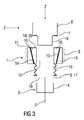
図1〜3は、本発明に記載のニードルアセンブリの取り外し可能デバイスの例示的な実施態様の概略の断面図を示す。 1-3 show a schematic cross-sectional view of an exemplary embodiment of a removable device of a needle assembly according to the present invention.
図1の例示的な実施態様で示す通り、ニードルアセンブリの取り外し可能デバイス1は、注射デバイス2に連結されたニードルアセンブリ3を取り外すために活用される。ニードルアセンブリ3は注射デバイス2の遠位端に嵌合するように適合されたニードルハブ4及びニードルハブ4に連結する針5を含み得る。針5は、注射デバイス2における薬剤カートリッジ内に挿入される近位部分を含み得て、そして患者の皮膚を穿孔し、そして薬剤の送達のための遠位部分を含み得る。ニードルハブ4が、ねじフィット、バヨネットフィット、スナップフィット、摩擦フィットなどを経由して注射デバイス2に連結し得る。 As shown in the exemplary embodiment of FIG. 1, the
例示的な実施態様において、注射デバイス2の遠位端は、ネック部分6、ネック部分6の近位にあるショルダ部分7、及びショルダ部分7の近位端にあるボディ部分8を含む。ボディ部分8は、薬剤カートリッジを囲み得て、そしてその遠位端でセプタムを含んでもよく、ここで、ニードルアセンブリ3が注射デバイスに連結されるとき、針5の近位部分により穿孔され得る。 In the exemplary embodiment, the distal end of the
例示的な実施態様において、ニードルアセンブリの取り外しデバイス1は、内側部分10及び外側部分15を含むハウジング9を含む。内側部分に形成されるチャンネル12は、近位開口部11及び遠位開口部18を含み得る。近位開口部11は、ニードルアセンブリ3のニードルハブ4を受け入れるように、サイズを決められ、形状を決められ得る。ハウジング9の外側部分15は、内側部分10を取り囲み得る。内側部分10は、インタフェースに沿って外側部分15に対して可動であり得る。例示的な実施態様において、インタフェースは、内側部分10上に形成される第一の傾斜面13及び外側部分15上に形成される第二の傾斜面14を含み得る。 In the exemplary embodiment, the needle
例示的な実施態様において、ばね16は、内側部分10の遠位端及びハウジング9の遠位端17に連結される。 In the exemplary embodiment,
図1における例示的な実施態様に示す通り、注射が投与された後、ニードルアセンブリ取り外しデバイス1は、ニードルアセンブリ3がチャンネル12の近位開口部11で受け入られるように、注射デバイス2上に置かれる。 As shown in the exemplary embodiment in FIG. 1, after an injection is administered, the needle
図2における例示的な実施態様に示すとおり、ニードルアセンブリ取り外しデバイス1は、内側部分10の近位端19が注射デバイス2のショルダ部分7に隣接するまで、第一の方向(例えば、近位に)に前進する。ニードルアセンブリの取り外しデバイス1は、更に、近位に前進するので、ばね16は圧縮し、そして外側部分15が内側部分10に対して近位に動く。外側部分15が内側部分10に対して、近位に動くので、外側部分15が内側部分10を押さえ、そして、近位開口部11の第一の幅を変化させる(例えば、低下させる)。近位開口部11が、第二の幅にあるとき、内側部分10がニードルアセンブリ3のニードルハブ4に係合する。インタフェースの曲がった方向付けに起因して、外側部分15の第一の方向への動きは、内側部分10を半径方向に動かす。ニードルハブ4の摩擦係合に起因して、ニードルアセンブリ3は、注射デバイス2に対してハウジング9を回転することにより取り外すことができる(例えば、ねじをまわしてはずす)。 As shown in the exemplary embodiment in FIG. 2, the needle
図3において例示的な実施態様で示す通り、ニードルアセンブリ3が注射デバイス2から取り外された後、ニードルアセンブリの取り外しデバイス1は、注射デバイス2から取り外され得る。ニードルアセンブリの取り外しデバイス1は、注射デバイス2から取り外されるとき、ばね6が伸び、そして外側部分15は、内側部分10に対して第二の方向(例えば、遠位に)に動く。外側部分15が、内側部分10に対して遠位に動くとき、内側部分10は外側の半径方向に動き、近位開口部11を第一の幅に戻ることを可能にし、それにより、ニードルアセンブリ3を解放する。近位開口部11又は遠位開口部18を容器に対して方向付けすることにより、ニードルアセンブリ3は処分され得る。遠位開口部18は第一の幅と同等又はそれより大きい第三の幅を有し得る。 As shown in the exemplary embodiment in FIG. 3, after the
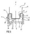
図4〜6は本発明に記載のニードルアセンブリの取り外しデバイス1の別の例示的な実施態様を示す。この例示的な実施態様において、ニードルアセンブリの取り外しデバイス1は、クランピングばね22を備えたハウジング9を含む。クランピングばね22は、近位開口部11と遠位開口部18を含む。クランピングばね22の近位開口部11は、ニードルアセンブリ3のニードルハブ4を受け入れるようにサイズを決め及び形状を決められ得る。スライダ21はハウジング9の近位開口部上に配置され、そしてクランピングばね22の近位部分に係合され得る。スライダ21がハウジング9に軸方向で可動に配設され得る。 4-6 show another exemplary embodiment of a needle
図4における例示的な実施態様で示す通り、注射を投与された後、ニードルアセンブリ取り外しデバイス1は、ニードルハブ4が、クランピングばね22の近位開口部11において受け入れるように心合わせするよう注射デバイス2と整合する。 As shown in the exemplary embodiment in FIG. 4, after the injection is administered, the needle
図5における例示的な実施態様で示す通り、ニードルアセンブリ取り外しデバイス1は、スライダ21の近端20が注射デバイス2のショルダ部分7に隣接するまで近位に前進する。ニードルアセンブリ取り外しデバイス1が更に近位に前進するとき、クランピングばね22が圧縮し、そしてスライダ21又はクランピングばね22のクランピング部24は、ニードルアセンブリ3のニードルハブを係合する。一つ又はそれ以上の止め具23は、ハウジング9に対してスライダ21の動きを制限するためにハウジング9内に形成され、又は逆もまたその通りである。この位置において、ニードルアセンブリ3がニードルアセンブリ取り外しデバイス1により係合されるとき、ニードルアセンブリ3は、注射デバイス2に対してハウジング9を回転することにより、取り外すことができる(例えば、ねじをまわしてはずす)。 As shown in the exemplary embodiment in FIG. 5, the needle
図6の例示的な実施態様で示す通り、ニードルアセンブリ3が注射デバイス2から取り外された後、ニードルアセンブリ取り外しデバイス1は、注射デバイス2から取り外され得る。ニードルアセンブリ取り外しデバイス1が注射デバイス2から取り外されるとき、クランピングばね6は伸長し、そしてスライダ21がハウジング9に対して近位に動く。スライダ21がハウジング9に対して近位に動くとき、スライダ21又はクランピングばね22のクランピング部24は、ニードルアセンブリ3を解放する。近位開口部11又は遠位開口部18を容器に対して方向付けすることにより、ニードルアセンブリ3が処分され得る。 As shown in the exemplary embodiment of FIG. 6, after the
当業者は、本明細書で記載したデバイス及び/又はシステム及び実施態様の様々な構成部材の改質(取付け及び/又は除去)は、そのような改質並びにそのいかなる及び全ての等価物も包含するが、本発明の完全な範囲及び精神から離れることなく作られ得ることを理解するであろう。 Those skilled in the art will appreciate that modifications (attachment and / or removal) of various components of the devices and / or systems and embodiments described herein include such modifications and any and all equivalents thereof. However, it will be understood that it can be made without departing from the full scope and spirit of the invention.
参照番号リスト
1:ニードルアセンブリの取り外しデバイス;
2:注射デバイス;
3:ニードルアセンブリ;
4:ニードルハブ;
5:針;
6:ネック部分;
7:ショルダ部分;
8:ボディ部分;
9:ハウジング;
10:内側部分;
11:近位開口部;
12:チャンネル;
13:第一の傾斜面;
14:第二の傾斜面;
15:外側部分;
16:ばね;
17:遠位端;
18:遠位開口部;
19:近位端;
20:近位端;
21:スライダ;
22:クランピングばね;
23:止め具;
24:クランピング部;
z:方向;Reference number list 1: Needle assembly removal device;
2: injection device;
3: Needle assembly;
4: Needle hub;
5: Needle;
6: neck part;
7: shoulder part;
8: Body part;
9: Housing;
10: inner part;
11: proximal opening;
12: Channel;
13: first inclined surface;
14: second inclined surface;
15: outer part;
16: Spring;
17: distal end;
18: distal opening;
19: proximal end;
20: proximal end;
21: Slider;
22: Clamping spring;
23: Stopper;
24: Clamping section;
z: direction;
Claims (9)
Translated fromJapanese内側部分(10);
内側部分(10)に形成され、近位開口部(11)を有するチャンネル(12);
内側部分(10)上に可動に配設された外側部分(15)、
を含んでなり、
ここで、内側部分(10)に対する外側部分(15)の第一の方向への動きにより、内側部分(10)が、近位開口部(11)を第一の幅から第二の幅へ変化させる、上記ニードルアセンブリの取り外しデバイス。A needle assembly removal device (1) comprising:
Inner part (10);
A channel (12) formed in the inner portion (10) and having a proximal opening (11);
An outer portion (15) movably disposed on the inner portion (10);
Comprising
Here, movement of the outer portion (15) in the first direction relative to the inner portion (10) causes the inner portion (10) to change the proximal opening (11) from the first width to the second width. A removal device of the needle assembly.
を更に含んでなる、請求項1〜7のいずれか1項に記載のニードルアセンブリの取り外しデバイス(1)。Spring (16) connected to the inner part (10):
The needle assembly removal device (1) according to any one of the preceding claims, further comprising:
ばね(16)が、内側部分(10)に対する外側部分(15)の第一の方向への動きの間、圧縮される請求項8に記載のニードルアセンブリの取り外しデバイス(1)。The needle assembly removal device (1) according to claim 8, wherein the spring (16) is compressed during movement of the outer part (15) in a first direction relative to the inner part (10).
Applications Claiming Priority (3)
| Application Number | Priority Date | Filing Date | Title |
|---|---|---|---|
| EP11168015.3 | 2011-05-30 | ||
| EP11168015AEP2529777A1 (en) | 2011-05-30 | 2011-05-30 | Needle assembly removal device |
| PCT/EP2012/059989WO2012163891A1 (en) | 2011-05-30 | 2012-05-29 | Needle assembly removal device |
Publications (1)
| Publication Number | Publication Date |
|---|---|
| JP2014516718Atrue JP2014516718A (en) | 2014-07-17 |
Family
ID=44991042
Family Applications (1)
| Application Number | Title | Priority Date | Filing Date |
|---|---|---|---|
| JP2014513149APendingJP2014516718A (en) | 2011-05-30 | 2012-05-29 | Needle assembly removal device |
Country Status (5)
| Country | Link |
|---|---|
| US (2) | US20140082933A1 (en) |
| EP (2) | EP2529777A1 (en) |
| JP (1) | JP2014516718A (en) |
| CA (1) | CA2836625A1 (en) |
| WO (1) | WO2012163891A1 (en) |
Cited By (1)
| Publication number | Priority date | Publication date | Assignee | Title |
|---|---|---|---|---|
| KR20160128251A (en)* | 2015-04-28 | 2016-11-07 | 주식회사 메덱셀 | Functional cover of the pen-type syringe |
Families Citing this family (5)
| Publication number | Priority date | Publication date | Assignee | Title |
|---|---|---|---|---|
| SE539276C2 (en)* | 2013-10-30 | 2017-06-13 | Danderyds Snickeri Ab | Method and apparatus for increasing safety when removing a cannula from a syringe |
| US10693269B2 (en) | 2016-06-28 | 2020-06-23 | Hubbell Incorporated | Splice assembly |
| EP4129108B1 (en) | 2017-05-31 | 2024-06-19 | Nike Innovate C.V. | Automated footwear lacing systems, devices, and techniques |
| US11744957B2 (en)* | 2017-12-28 | 2023-09-05 | Embecta Corp. | Pen needle assembly apparatus |
| CN110732062B (en)* | 2019-08-02 | 2021-07-20 | 宁波市北仑区人民医院 | Needle device is unloaded to formula of pushing down |
Citations (4)
| Publication number | Priority date | Publication date | Assignee | Title |
|---|---|---|---|---|
| JP2003533291A (en)* | 2000-05-15 | 2003-11-11 | アレス トレーディング ソシエテ アノニム | A device for separating the connection end of a hypodermic needle from the tip of the injection device |
| WO2004075806A1 (en)* | 2003-02-27 | 2004-09-10 | Showa Yakuhin Kako Co.,Ltd. | Syringe needle removing device for dental cartridge type syringes |
| JP2009225825A (en)* | 2008-03-19 | 2009-10-08 | Terumo Corp | Syringe needle remover and syringe needle disposal container |
| WO2010113388A1 (en)* | 2009-03-31 | 2010-10-07 | 株式会社みくに工業 | Container for collecting needle to be discarded and part for collecting needle to be discarded |
Family Cites Families (5)
| Publication number | Priority date | Publication date | Assignee | Title |
|---|---|---|---|---|
| BE1007352A3 (en)* | 1993-07-20 | 1995-05-23 | Moubax Jozef | Device for releasing used hypodermic needles |
| US6712207B2 (en)* | 2001-08-21 | 2004-03-30 | Tyco Healthcare Group Lp | Apparatus and method for unwinding a needle portion |
| US7984805B2 (en)* | 2005-08-31 | 2011-07-26 | Griff Industries Inc | Medical sharps retardation apparatus and a method of retarding medical sharps from future use |
| US20090014462A1 (en)* | 2007-07-10 | 2009-01-15 | Pharmadesign, Inc. | Needle dispenser system and hand tool for same |
| US20120145577A1 (en)* | 2009-04-30 | 2012-06-14 | Sanofi-Aventis Deutschland Gmbh | Needle remover and method for removing a needle |
- 2011
- 2011-05-30EPEP11168015Apatent/EP2529777A1/ennot_activeCeased
- 2012
- 2012-05-29USUS14/119,214patent/US20140082933A1/ennot_activeAbandoned
- 2012-05-29CACA2836625Apatent/CA2836625A1/ennot_activeAbandoned
- 2012-05-29EPEP12726060.2Apatent/EP2714154A1/ennot_activeWithdrawn
- 2012-05-29WOPCT/EP2012/059989patent/WO2012163891A1/enactiveApplication Filing
- 2012-05-29JPJP2014513149Apatent/JP2014516718A/enactivePending
- 2015
- 2015-04-15USUS14/686,946patent/US20150217062A1/ennot_activeAbandoned
Patent Citations (4)
| Publication number | Priority date | Publication date | Assignee | Title |
|---|---|---|---|---|
| JP2003533291A (en)* | 2000-05-15 | 2003-11-11 | アレス トレーディング ソシエテ アノニム | A device for separating the connection end of a hypodermic needle from the tip of the injection device |
| WO2004075806A1 (en)* | 2003-02-27 | 2004-09-10 | Showa Yakuhin Kako Co.,Ltd. | Syringe needle removing device for dental cartridge type syringes |
| JP2009225825A (en)* | 2008-03-19 | 2009-10-08 | Terumo Corp | Syringe needle remover and syringe needle disposal container |
| WO2010113388A1 (en)* | 2009-03-31 | 2010-10-07 | 株式会社みくに工業 | Container for collecting needle to be discarded and part for collecting needle to be discarded |
Cited By (2)
| Publication number | Priority date | Publication date | Assignee | Title |
|---|---|---|---|---|
| KR20160128251A (en)* | 2015-04-28 | 2016-11-07 | 주식회사 메덱셀 | Functional cover of the pen-type syringe |
| KR102317977B1 (en) | 2015-04-28 | 2021-10-28 | 주식회사 메덱셀 | Functional cover of the pen-type syringe |
Also Published As
| Publication number | Publication date |
|---|---|
| EP2714154A1 (en) | 2014-04-09 |
| US20140082933A1 (en) | 2014-03-27 |
| WO2012163891A1 (en) | 2012-12-06 |
| EP2529777A1 (en) | 2012-12-05 |
| US20150217062A1 (en) | 2015-08-06 |
| CA2836625A1 (en) | 2012-12-06 |
Similar Documents
| Publication | Publication Date | Title |
|---|---|---|
| US9078983B2 (en) | Prefilled safety pen needle | |
| CN102470219B (en) | Safety pen needle device | |
| CN204428546U (en) | There is the syringe of scalable penetration depth | |
| US10661020B2 (en) | Medication delivery device | |
| EP2726123B1 (en) | Needle assembly attachment and removal device | |
| JP7374105B2 (en) | Injection system with syringe and protection assembly | |
| CN111163819A (en) | Needle shield puller for drug delivery system | |
| EP2572745A1 (en) | Needle safety device | |
| US20210077723A1 (en) | Auto-injection drug delivery device | |
| CN110694143B (en) | Syringe assembly | |
| CN103025374A (en) | Safety device for a pre-filled syringe, injection device and injection kit | |
| JP2014516718A (en) | Needle assembly removal device | |
| EP2732835A1 (en) | Needle assembly magazine | |
| US12251543B2 (en) | Variable length injection syringe | |
| EP2661297B1 (en) | Injection device comprising a pre-filled syringe and a safety device | |
| US20130184678A1 (en) | Dual action syringe | |
| JP2008510546A (en) | Injection device including a syringe | |
| EP2586480A1 (en) | Needle hub and disposal device for single-use needle assemblies | |
| JP2024522024A (en) | Accident prevention needle device | |
| EP2559447A1 (en) | Single-use needle assembly and storage device | |
| HK1192174A (en) | Needle assembly attachment and removal device | |
| HK1192174B (en) | Needle assembly attachment and removal device |
Legal Events
| Date | Code | Title | Description |
|---|---|---|---|
| A621 | Written request for application examination | Free format text:JAPANESE INTERMEDIATE CODE: A621 Effective date:20150518 | |
| A977 | Report on retrieval | Free format text:JAPANESE INTERMEDIATE CODE: A971007 Effective date:20160315 | |
| A131 | Notification of reasons for refusal | Free format text:JAPANESE INTERMEDIATE CODE: A131 Effective date:20160329 | |
| A02 | Decision of refusal | Free format text:JAPANESE INTERMEDIATE CODE: A02 Effective date:20161108 |