JP2014516459A - LED lamp - Google Patents
LED lampDownload PDFInfo
- Publication number
- JP2014516459A JP2014516459AJP2014505228AJP2014505228AJP2014516459AJP 2014516459 AJP2014516459 AJP 2014516459AJP 2014505228 AJP2014505228 AJP 2014505228AJP 2014505228 AJP2014505228 AJP 2014505228AJP 2014516459 AJP2014516459 AJP 2014516459A
- Authority
- JP
- Japan
- Prior art keywords
- heat
- heat sink
- fins
- heat spreader
- base
- Prior art date
- Legal status (The legal status is an assumption and is not a legal conclusion. Google has not performed a legal analysis and makes no representation as to the accuracy of the status listed.)
- Pending
Links
- 239000004033plasticSubstances0.000claimsdescription11
- 229920003023plasticPolymers0.000claimsdescription11
- 238000006243chemical reactionMethods0.000claimsdescription10
- 230000003287optical effectEffects0.000claims2
- 239000000463materialSubstances0.000description16
- 230000008901benefitEffects0.000description10
- 230000009286beneficial effectEffects0.000description8
- 230000008859changeEffects0.000description8
- XAGFODPZIPBFFR-UHFFFAOYSA-NaluminiumChemical compound[Al]XAGFODPZIPBFFR-UHFFFAOYSA-N0.000description7
- 229910052782aluminiumInorganic materials0.000description7
- 238000007726management methodMethods0.000description7
- 238000007747platingMethods0.000description6
- 230000000712assemblyEffects0.000description5
- 238000000429assemblyMethods0.000description5
- 239000004593EpoxySubstances0.000description4
- 229910000679solderInorganic materials0.000description4
- 239000004020conductorSubstances0.000description3
- 239000011810insulating materialSubstances0.000description3
- 238000000465mouldingMethods0.000description3
- RYGMFSIKBFXOCR-UHFFFAOYSA-NCopperChemical compound[Cu]RYGMFSIKBFXOCR-UHFFFAOYSA-N0.000description2
- 239000000853adhesiveSubstances0.000description2
- 230000001070adhesive effectEffects0.000description2
- AZDRQVAHHNSJOQ-UHFFFAOYSA-NalumaneChemical group[AlH3]AZDRQVAHHNSJOQ-UHFFFAOYSA-N0.000description2
- 238000003491arrayMethods0.000description2
- 239000002131composite materialSubstances0.000description2
- 229910052802copperInorganic materials0.000description2
- 239000010949copperSubstances0.000description2
- 230000017525heat dissipationEffects0.000description2
- 238000005286illuminationMethods0.000description2
- 230000013011matingEffects0.000description2
- 230000009467reductionEffects0.000description2
- 239000000758substrateSubstances0.000description2
- 238000004873anchoringMethods0.000description1
- 239000011248coating agentSubstances0.000description1
- 238000000576coating methodMethods0.000description1
- 238000010276constructionMethods0.000description1
- 238000010292electrical insulationMethods0.000description1
- 239000012777electrically insulating materialSubstances0.000description1
- 238000005516engineering processMethods0.000description1
- 238000004519manufacturing processMethods0.000description1
- 239000007769metal materialSubstances0.000description1
- 238000000034methodMethods0.000description1
- 238000012986modificationMethods0.000description1
- 230000004048modificationEffects0.000description1
- 230000008520organizationEffects0.000description1
- 238000004382pottingMethods0.000description1
- 230000008569processEffects0.000description1
- 238000002310reflectometryMethods0.000description1
- 230000035945sensitivityEffects0.000description1
- 238000007493shaping processMethods0.000description1
Images


Classifications
- F—MECHANICAL ENGINEERING; LIGHTING; HEATING; WEAPONS; BLASTING
- F28—HEAT EXCHANGE IN GENERAL
- F28F—DETAILS OF HEAT-EXCHANGE AND HEAT-TRANSFER APPARATUS, OF GENERAL APPLICATION
- F28F3/00—Plate-like or laminated elements; Assemblies of plate-like or laminated elements
- F28F3/02—Elements or assemblies thereof with means for increasing heat-transfer area, e.g. with fins, with recesses, with corrugations
- F—MECHANICAL ENGINEERING; LIGHTING; HEATING; WEAPONS; BLASTING
- F21—LIGHTING
- F21K—NON-ELECTRIC LIGHT SOURCES USING LUMINESCENCE; LIGHT SOURCES USING ELECTROCHEMILUMINESCENCE; LIGHT SOURCES USING CHARGES OF COMBUSTIBLE MATERIAL; LIGHT SOURCES USING SEMICONDUCTOR DEVICES AS LIGHT-GENERATING ELEMENTS; LIGHT SOURCES NOT OTHERWISE PROVIDED FOR
- F21K9/00—Light sources using semiconductor devices as light-generating elements, e.g. using light-emitting diodes [LED] or lasers
- F21K9/20—Light sources comprising attachment means
- F21K9/23—Retrofit light sources for lighting devices with a single fitting for each light source, e.g. for substitution of incandescent lamps with bayonet or threaded fittings
- F21K9/233—Retrofit light sources for lighting devices with a single fitting for each light source, e.g. for substitution of incandescent lamps with bayonet or threaded fittings specially adapted for generating a spot light distribution, e.g. for substitution of reflector lamps
- F—MECHANICAL ENGINEERING; LIGHTING; HEATING; WEAPONS; BLASTING
- F21—LIGHTING
- F21K—NON-ELECTRIC LIGHT SOURCES USING LUMINESCENCE; LIGHT SOURCES USING ELECTROCHEMILUMINESCENCE; LIGHT SOURCES USING CHARGES OF COMBUSTIBLE MATERIAL; LIGHT SOURCES USING SEMICONDUCTOR DEVICES AS LIGHT-GENERATING ELEMENTS; LIGHT SOURCES NOT OTHERWISE PROVIDED FOR
- F21K9/00—Light sources using semiconductor devices as light-generating elements, e.g. using light-emitting diodes [LED] or lasers
- F21K9/60—Optical arrangements integrated in the light source, e.g. for improving the colour rendering index or the light extraction
- F—MECHANICAL ENGINEERING; LIGHTING; HEATING; WEAPONS; BLASTING
- F21—LIGHTING
- F21V—FUNCTIONAL FEATURES OR DETAILS OF LIGHTING DEVICES OR SYSTEMS THEREOF; STRUCTURAL COMBINATIONS OF LIGHTING DEVICES WITH OTHER ARTICLES, NOT OTHERWISE PROVIDED FOR
- F21V29/00—Protecting lighting devices from thermal damage; Cooling or heating arrangements specially adapted for lighting devices or systems
- F21V29/50—Cooling arrangements
- F21V29/70—Cooling arrangements characterised by passive heat-dissipating elements, e.g. heat-sinks
- F21V29/71—Cooling arrangements characterised by passive heat-dissipating elements, e.g. heat-sinks using a combination of separate elements interconnected by heat-conducting means, e.g. with heat pipes or thermally conductive bars between separate heat-sink elements
- F21V29/713—Cooling arrangements characterised by passive heat-dissipating elements, e.g. heat-sinks using a combination of separate elements interconnected by heat-conducting means, e.g. with heat pipes or thermally conductive bars between separate heat-sink elements in direct thermal and mechanical contact of each other to form a single system
- F—MECHANICAL ENGINEERING; LIGHTING; HEATING; WEAPONS; BLASTING
- F21—LIGHTING
- F21V—FUNCTIONAL FEATURES OR DETAILS OF LIGHTING DEVICES OR SYSTEMS THEREOF; STRUCTURAL COMBINATIONS OF LIGHTING DEVICES WITH OTHER ARTICLES, NOT OTHERWISE PROVIDED FOR
- F21V29/00—Protecting lighting devices from thermal damage; Cooling or heating arrangements specially adapted for lighting devices or systems
- F21V29/50—Cooling arrangements
- F21V29/70—Cooling arrangements characterised by passive heat-dissipating elements, e.g. heat-sinks
- F21V29/74—Cooling arrangements characterised by passive heat-dissipating elements, e.g. heat-sinks with fins or blades
- F21V29/77—Cooling arrangements characterised by passive heat-dissipating elements, e.g. heat-sinks with fins or blades with essentially identical diverging planar fins or blades, e.g. with fan-like or star-like cross-section
- F21V29/773—Cooling arrangements characterised by passive heat-dissipating elements, e.g. heat-sinks with fins or blades with essentially identical diverging planar fins or blades, e.g. with fan-like or star-like cross-section the planes containing the fins or blades having the direction of the light emitting axis
- F—MECHANICAL ENGINEERING; LIGHTING; HEATING; WEAPONS; BLASTING
- F21—LIGHTING
- F21V—FUNCTIONAL FEATURES OR DETAILS OF LIGHTING DEVICES OR SYSTEMS THEREOF; STRUCTURAL COMBINATIONS OF LIGHTING DEVICES WITH OTHER ARTICLES, NOT OTHERWISE PROVIDED FOR
- F21V29/00—Protecting lighting devices from thermal damage; Cooling or heating arrangements specially adapted for lighting devices or systems
- F21V29/50—Cooling arrangements
- F21V29/70—Cooling arrangements characterised by passive heat-dissipating elements, e.g. heat-sinks
- F21V29/83—Cooling arrangements characterised by passive heat-dissipating elements, e.g. heat-sinks the elements having apertures, ducts or channels, e.g. heat radiation holes
- F—MECHANICAL ENGINEERING; LIGHTING; HEATING; WEAPONS; BLASTING
- F21—LIGHTING
- F21V—FUNCTIONAL FEATURES OR DETAILS OF LIGHTING DEVICES OR SYSTEMS THEREOF; STRUCTURAL COMBINATIONS OF LIGHTING DEVICES WITH OTHER ARTICLES, NOT OTHERWISE PROVIDED FOR
- F21V29/00—Protecting lighting devices from thermal damage; Cooling or heating arrangements specially adapted for lighting devices or systems
- F21V29/50—Cooling arrangements
- F21V29/70—Cooling arrangements characterised by passive heat-dissipating elements, e.g. heat-sinks
- F—MECHANICAL ENGINEERING; LIGHTING; HEATING; WEAPONS; BLASTING
- F21—LIGHTING
- F21Y—INDEXING SCHEME ASSOCIATED WITH SUBCLASSES F21K, F21L, F21S and F21V, RELATING TO THE FORM OR THE KIND OF THE LIGHT SOURCES OR OF THE COLOUR OF THE LIGHT EMITTED
- F21Y2115/00—Light-generating elements of semiconductor light sources
- F21Y2115/10—Light-emitting diodes [LED]
Landscapes
- Engineering & Computer Science (AREA)
- General Engineering & Computer Science (AREA)
- Physics & Mathematics (AREA)
- Microelectronics & Electronic Packaging (AREA)
- Optics & Photonics (AREA)
- Thermal Sciences (AREA)
- Mechanical Engineering (AREA)
- Arrangement Of Elements, Cooling, Sealing, Or The Like Of Lighting Devices (AREA)
- Led Device Packages (AREA)
- Non-Portable Lighting Devices Or Systems Thereof (AREA)
Abstract
Translated fromJapaneseDescription
Translated fromJapanese(関連出願)
本出願は、2011年4月11日に出願された、米国特許仮出願第61/474,077号に対する優先権を主張し、その全体が参照により本明細書に組み込まれる。(Related application)
This application claims priority to US Provisional Application No. 61 / 474,077, filed Apr. 11, 2011, which is hereby incorporated by reference in its entirety.
本発明は、照明の分野に関し、より具体的には、発光ダイオードを用いて使用するためのランプに関する。 The present invention relates to the field of lighting, and more particularly to lamps for use with light emitting diodes.
典型的に、照明器具設計者は、全光出力(効率)と放射された光の所望の占有面積との間に所望の妥協をもたらすように、従来の既知の光源を使用し、放射された光を成形することに努力を集中させてきた。熱管理のような問題はあまり重要でなかった。しかしながら、発光ダイオード(LED)によって、時間経過に伴う光出力の変化、直流電力への変換に対する潜在的な必要性、および慎重な熱管理の必要性のような問題がより重大になってきている。さらに複雑なことに、LED技術が急速に進化し続け、LEDを器具に直接組み込む器具を設計することが困難になっている。 Typically, luminaire designers have used conventional known light sources to radiate to provide the desired compromise between total light output (efficiency) and the desired occupied area of emitted light. Efforts have been focused on shaping light. Issues like thermal management were not very important. However, light emitting diodes (LEDs) are making problems such as changes in light output over time, the potential need for conversion to DC power, and the need for careful thermal management become more serious. . To complicate matters, LED technology continues to evolve rapidly, making it difficult to design devices that incorporate LEDs directly into the device.
LEDに関する1つの既知の問題は、LEDの潜在耐用年数が維持され得るようにLEDの温度を十分に冷たく保つことが重要であるということである。そうしなければ、熱がLEDの光出力を短時間で劣化させ、そうでない場合にLEDが適切に機能しなくなるよりかなり前に、LEDが定格光出力を提供しなくなる。したがって、LEDの熱出力が極度ではないが、熱に対するLEDの相対感度は、熱管理を比較的重要な問題にさせている。既存の設計は、発生した熱を完全には考慮していないか、比較的制限されたルーメン出力を提供する傾向があるか、またはLED交換用電球の設計を極めて費用のかかる高価な熱管理解決法を使用する傾向がある。したがって、人々が費用効率の高い解決法を熱管理の問題に提供し得るLED光モジュールのさらなる改善を理解するであろう。 One known problem with LEDs is that it is important to keep the LED temperature cold enough so that the LED's potential useful life can be maintained. Otherwise, heat will quickly degrade the light output of the LED, otherwise the LED will not provide a rated light output long before the LED fails to function properly. Thus, although the LED thermal output is not extreme, the relative sensitivity of the LED to heat makes thermal management a relatively important issue. Existing designs do not fully account for the generated heat, tend to provide a relatively limited lumen output, or expensive replacement of LED replacement bulbs is an expensive thermal management solution There is a tendency to use the law. Thus, people will understand further improvements in LED light modules that can provide a cost-effective solution to the problem of thermal management.
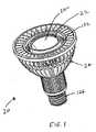
ランプが、基部に装着される発光ダイオード(LED)を含み、ヒートスプレッダに熱的に結合され、順にヒートシンクに熱的に接合される。ヒートシンクは、基部と、該基部から延在する複数のフィンとを有する。ヒートスプレッダは、基部によって支持され、熱をLEDからヒートシンクへ移動させるのを促す。一実施形態では、それぞれのフィンが、基部から外方に延在する下部と、基部から上方に延在し、かつ下部からオフセットされる上部とを含む。それぞれの上部を通って開口が提供され、そこを通って空気が通過するのを可能にしてもよい。別の実施形態では、ヒートスプレッダは、フィンおよびヒートシンクを含む。ヒートスプレッダは、ヒートシンクよりも前方にさらに延在し、熱管理を提供するのに役立てることができる。それぞれの実施形態では、ランプの高さは、500ルーメン超の出力を可能にしながら90mm未満であり得る。 The lamp includes a light emitting diode (LED) mounted to the base and is thermally coupled to the heat spreader and in turn thermally bonded to the heat sink. The heat sink has a base and a plurality of fins extending from the base. The heat spreader is supported by the base and facilitates the transfer of heat from the LED to the heat sink. In one embodiment, each fin includes a lower portion extending outward from the base and an upper portion extending upward from the base and offset from the lower portion. An opening may be provided through each upper portion to allow air to pass therethrough. In another embodiment, the heat spreader includes fins and a heat sink. The heat spreader extends further forward than the heat sink and can help provide thermal management. In each embodiment, the lamp height may be less than 90 mm while allowing an output greater than 500 lumens.
本発明の構造および運用の組織および様式は、そのさらなる目的および利点とともに、類似の参照番号が類似の要素を特定する添付図面と併せて読むことにより、以下の説明を参照しながら最良に理解することができる。 The organization and mode of operation and operation of the present invention, together with its further objects and advantages, are best understood by referring to the following description when read in conjunction with the accompanying drawings, wherein like reference numerals identify like elements. be able to.
本発明は、異なる形の実施形態として表わすことができるが、図面に示され、本開示が例示と見なされ、本明細書に例示され、記載されるような実施形態に本発明を限定することを意図しないことを理解して、本明細書で詳細な特定の実施形態に記載される。したがって、特に断らない限り、本明細書に開示される特徴は、簡潔さの目的のためにそれ以外に示されなかったさらなる組み合わせを形成するように組み合わせられてもよい。下部、上部などの用語が開示される実施形態を説明するのを容易にするために使用されるが、これらの用語が開示されるモジュールの使用のために必要とされる配向を示さないことが理解されるべきである。 While the invention may be represented as different forms of embodiments, it is to be understood that the present disclosure is to be considered illustrative and limited to the embodiments as illustrated and described herein. Are described in particular embodiments in detail herein. Thus, unless stated otherwise, the features disclosed herein may be combined to form further combinations not otherwise indicated for the sake of brevity. The terms bottom, top, etc. are used to facilitate describing the disclosed embodiments, but these terms may not indicate the orientation required for use of the disclosed module. Should be understood.
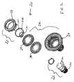
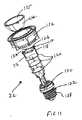
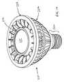
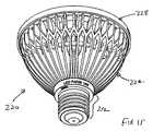
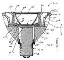
ランプ20、220(放物面反射鏡型ランプであると示されるような)が、LEDアセンブリ22、222と、LEDアセンブリ22、222によって生成される熱を放出させるためのヒートシンクアセンブリ24、224とを含む。ヒートシンクアセンブリ24、224は、ヒートシンク26、226と、ヒートスプレッダ28、228とを含む。ヒートシンク26、226とヒートスプレッダ28、228との間に熱パッド30が位置決めされてもよい。ヒートシンクアセンブリ24の一実施形態が図1〜12に示され、ヒートシンクアセンブリ224の別の実施形態が図14〜22に示される。
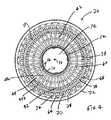
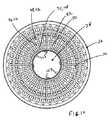
図1〜12に示されるヒートシンクアセンブリ24の実施形態に注意が喚起される。図3〜7に最良に示されるように、ヒートシンク26は、中央通路34を有する円筒状基部32を含み、そこを通って中心線36を画定する。複数の離間配置された細長いフィン38が基部32から延在する。それぞれのフィン38は、基部32から外方に延在する下部39と、基部32から上方に延在する上部62とを有する。 Attention is drawn to the embodiment of the
図7に最良に示されるように、それぞれのフィン38の下部39は、真っすぐであり、基部32から半径方向に外方に延在する下部セクション40と、基部32から半径方向に外方に延在する上部セクション42とを有する。それぞれの下部セクション40の図6の外縁44が同心円に沿う。これらの下部セクション40は真っすぐかつ半径方向として示されるが、他の形状が所望されるように使用され得る(例えば、下部セクション40は、波状であり、および/または基部32に対してある角度で延在してもよい)。それぞれのフィン38の上部セクション42は、それぞれの下部セクション40と垂直に整合される。それぞれの上部セクション42は、下部セクション40から上方に延在し、それぞれの下部セクション40に対して外方に湾曲する外縁46を有する。結果として、隣接する下部セクション40と上部セクション42との間に図4の垂直チャネル48が形成され、空気が基部32の底端部50から基部32の上端部52に循環することを可能にする。 As best shown in FIG. 7, the
図5に最良に示されるように、基部32の上端部52は、内側リング54を形成するように厚くされる。等間隔に離間配置された場所で、埋め立てられた領域56が、上部セクション42間の内側リング54から外方に延在し、ヒートスプレッダ28および熱パッド30(提供される場合)をヒートシンク26に取り付けるためにその中に孔58を有する固着点を提供する。図示されるように、基部32から離間配置される位置で隣接する上部セクション42間に弓状片60が提供され、そのため弓状片60および上部セクション42によってリングが形成される。このリングは、それぞれの垂直チャネル48を基部32の上端部52で内側セクション48aおよび外側セクション48bに分割する。 As best shown in FIG. 5, the
それぞれのフィン38の上部62は、上部セクション42から上方に延在し、基部32から離間配置される。図6に最良に示されるように、それぞれの上部62は、上部セクション42に対してある角度で延在する下部セクション64と、下部セクション64から上方に延在する上部セクション66とを含む。上部セクション66および上部セクション42は、互いに平行であるが、互いにオフセットされる。それぞれの上部62の外表面および上部セクション42の外表面は、上部セクション42の曲線を続ける。下部セクション64および上部セクション66の内表面65は、中心線36に平行に延在し、同心円に沿う。それぞれの上部セクション66の上端部67は、平坦であり、内表面65に概ね垂直である。 The
垂直チャネル48から隣接する上部セクション66間に形成されるチャネル70(図6参照)に流路を生成する下部セクション64を通って開口68が提供される。所望される場合、図面に示されるように、開口68は、下部セクション64から上部セクション66へ上方に延在し、より大きな空気流路を提供することができる。上部セクション66の上部の外端部69で図5および6参照の外側リング72が提供され、ともに上部セクション66に接続する。 An
ヒートシンク26の構造の結果として、フィン38によって複数のチャネル48、70が形成され、空気が基部32の底端部50からフィン38の上端部69に循環することを可能にする。開口68は、ヒートシンク26に沿って効率的な伝熱を提供するのに役立ち、そしてヒートシンク26の重量を最小限にしながら、フィン38にわたってより均一の温度を提供する。加えて、開口68は、空気がヒートシンク26を通って循環されるときに空気中に乱気流を促し、ヒートシンク26による放熱に役立つ。 As a result of the structure of the
所望される場合、図面に示されるように、それぞれのフィン38の上部セクション66を隣接するフィン38の上部セクション42に接続するように二次下部セクション74が提供され得る。二次下部セクション74は、下部セクション64に対して、かつ上部セクション42に対して角度を成す。このような二次下部セクション74が提供される場合、二次下部セクション74を通って開口76が提供され、垂直チャネル48から隣接する上部セクション66間に形成されるチャネル70にさらなる流路を形成してもよく、下部セクション64、74と上部セクション66とリング72との間に図4の別個のチャネル78が形成される。したがって、二次下部セクション74が提供される場合、図6に示されるように、一方のフィン38の上部セクション42、下部セクション64、および上部セクション66、ならびに隣接するフィン38の二次下部セクション74および上部セクション66によってY字型が概ね形成される。尖った角を有してY字型が示されるが、これらの角は、U字型が形成されるように丸みを帯びる可能性もあり、あるいは下部セクション66、74は、T字型が形成されるように水平である可能性もあることが理解されるべきである。 If desired, a secondary
図8に示されるように、ヒートスプレッダ28は、それぞれの上部セクション42の内表面43が沿う共通の円の形状に適合する外側の円形縁90を有するプレート88を含む。ヒートスプレッダ28は、同心円状に整合され、ヒートスプレッダ28の中心線94から半径方向に離間配置される開口92の第1の列と、互いに等間隔に離間配置され、同心円状に整合され、かつヒートスプレッダ28の中心線94から半径方向に離間配置される開口96の第2の列と、互いに等間隔に離間配置され、同心円状に整合され、かつヒートスプレッダ28の中心線94から半径方向に離間配置される開口98の第3の列とを含む。開口92の第1の列は、中心線94に最も近く、開口96の第2の列は、第1の列で開口92から半径方向に外方に位置決めされ、開口98の第3の列は、第2の列で開口96から半径方向に外方に位置決めされる。開口98の第3の列は、縁90に近接するが、そこから離間配置される。第1の列の開口92は、3つの組に分けられる。それぞれの組で、開口92は、互いに等間隔に離間配置される。第1の列で開口92のそれぞれの組の間で、締結具がLEDアセンブリ22をヒートシンク26に取り付けるために取り付けられるプレート88を通って貫通穴100が提供される。図示されるように、開口92、96、98のサイズは、第1の組から第2の組、第2の組から第3の組に増大する。LEDアセンブリ22をヒートスプレッダ28に取り付けるために開口92の第1の組の内方にプレート88を通って複数の貫通穴102が提供される。ヒートスプレッダ28は、薄く、熱伝導性であり、銅、アルミニウム、または高い熱伝導率を有する任意の他の材料等の材料から形成される可能性があり、この材料は、LEDアセンブリ22とヒートシンク26の外縁との間に低い熱抵抗率を提供することを促すことができ、一実施形態では、摂氏2度毎ワット(C/W)未満であり得る。 As shown in FIG. 8, the
ヒートスプレッダ28は、0.5mmを超える厚さ(上面(LEDアセンブリ22に隣接する)から底面(ヒートシンク26に近接する))を有する。ほとんどの用途では、高熱伝導性材料(例えば、100W/m−K超の熱伝導率を有する材料)がヒートスプレッダ28に使用されるとき、厚さ約1.2mmを超えるヒートスプレッダ28を有することに対する利点低下があり、1.5mm未満の厚さを有することは重量の観点から有益であり得ることが判明された。そのように示されたが、より高いワット数用途(例えば、12ワット超)では、より厚いヒートスプレッダ28がいくつかの利点をさらに提供する場合がある。 The
図9に示されるように、ヒートスプレッダ28の片側に熱パッド30(必要ではないが好ましい)が装着され、ヒートシンク26とヒートスプレッダ28との間に提供される。熱パッド30は、例えば、3Mの熱伝導性接着剤転写テープ8810等の熱伝導性接着ガスケットであり得、バルク貯蔵品から所望の形状に切除/刻まれ、従来の方法で適用され得る。図示されるように、熱パッド30は、そこを通って中央開口106を画定するリング状の本体104である。熱パッド30は、ヒートスプレッダ28を通って開口92の第1の列と整合し、それに形状で適合する開口110の第1の列と、ヒートスプレッダ28を通って開口96の第2の列と整合し、それに形状で適合する開口110の第2の列と、ヒートスプレッダ28を通って開口98の第3の列と整合し、それに形状で適合する開口112の第3の列とを含む。ヒートスプレッダ28の貫通穴102は、熱パッド30の中央開口106に隣接して位置決めされる。熱パッド30は、厚さを有し、熱的に効率的な系統が所望される場合、熱パッド30がヒートスプレッダ28の熱伝導率よりも1桁以上低い熱伝導率を有する傾向があるときに可能であれば厚さを減少させることが望ましい。一実施形態では、熱パッド30の厚さは、約1.0mmまたはそれ未満であり得、他の実施形態では、0.5mm未満であってもよい。 As shown in FIG. 9, a heat pad 30 (preferably, but not necessary) is attached to one side of the
ヒートスプレッダ28/熱パッド30は、内側リング54、埋め立てられた領域56、上部セクション42、および弓状片60に着座する。第1の列および第2の列の開口96/110、92/108は、ヒートシンク26のチャネル48aと整合する。第3の列の開口98/112は、ヒートシンク26のチャネル48bと整合する。貫通穴100は、領域56内の孔58と整合し、従来のねじ、押しピン型コネクタ、またはいくつかの他の締結具であってもよい締結具が、そこを通って提供され、ヒートスプレッダ28/熱パッド30をヒートシンク26に強固に結合する。熱パッド30の中央開口106は、ヒートシンク26の基部32を通って中央通路34に形状で適合するようにサイズ決めされる。結果として、ヒートスプレッダ28およびヒートシンク26は、実質的な重複領域を有する。当然ながら、すべての他の条件が等しいならば、領域を増大することは、ヒートスプレッダ28とヒートシンク26との間の熱抵抗率を低下させるのを促す傾向がある。熱パッド30が薄く、比較的高い熱伝導率を有するため、次にLEDアセンブリ22のLEDのサイズの3倍または5倍だけである均一な重複領域は、十分に低いLEDアセンブリ22のLEDとヒートシンク26との間に熱抵抗率を提供するのに十分である場合がある。 The
図2および11に示されるように、LEDアセンブリ22は、LEDモジュール114と、LEDモジュール114およびボード120(それぞれが従来のプリント回路で形成されてもよく、あるいは誘電体層に提供されるトレースであり得る)に接続される陽極116および陰極118と、基部アセンブリ122とを含む。 As shown in FIGS. 2 and 11, the
図11に最良に示されるように、LEDモジュール114は、絶縁基部124と、基部124に着座されるLEDと、基部124に着座され、LEDを覆うLEDカバー126とを含む。LEDは、単一LEDまたはアレイであってもよい。基部124は電子部品を収容する。基部124を通って複数の開口が提供される。陽極116および陰極118は、LEDに接続され、基部124を通って延在し、最上部のボード120に接続する。基部124の下面に熱パックまたは相変化パッドが提供されてもよい。熱パック/相変化パッドは、LEDモジュール114に統合され、熱伝導性エポキシによってそれに取り付けられる導電素子であってもよい。代替的な実施形態では、熱パック/相変化パッドは、熱伝導性エポキシまたははんだなど(それに限定しない)、分配された導電材料であり得る。 As best shown in FIG. 11, the
LEDモジュール114は、ヒートスプレッダ28の上面に着座し、そのため熱パック/相変化パッドが、提供される場合、ヒートスプレッダ28に接触する。したがって、ヒートスプレッダ28は、LEDモジュール114の下面とヒートシンク26との間に位置決めされる。ヒートスプレッダ28は、LEDモジュール114(または提供される場合、熱パック)の下面に隣接し、そのためLEDがヒートスプレッダ28に熱的に結合される。陽極116および陰極118は、ヒートスプレッダ28内の開口102のうちの2つを通って、かつ最上部のボード120に接続するために熱パッド30の中央通路106を通って延在する。 The
図示されるのが3つの数であるようなボード120は、LEDモジュール114の基部124の下に位置決めされ、それから離間配置される。ボード120は、電子部品を収容し、基部アセンブリ122、ならびに陽極116および陰極118に電気的に結合される。ボード120上の電子部品は、AC/DC変換をLEDモジュール114に提供してもよい。ボード120は典型的に、囲まれ、または注封材料(図示せず)で注封され、ヒートシンク26の基部32の中央通路34内に着座される。 A
1つ以上のLEDがLEDモジュール114で使用され、LEDアレイを提供することができ、LED(複数可)は、交流または直流電力によって作動されるように設計され得る。交流LEDを使用する利点は、従来のAC線間電圧を直流電圧に変換する必要性がないことである。これは、電力変換器回路が、高価になる傾向があるか、またはLED自体が持続することができる限り、持続する可能性が高くないかのいずれかであるときに費用が重要な推進力である場合に有利であり得る。したがって、LED器具から期待される30,000〜70,000時間を得るために、交流LEDの使用は有益であり得る。しかしながら、外部AC/DC変換がある用途では(例えば、線間電圧を有することが望ましくない用途では)、直流LEDは、既存の直流LEDが優れた性能を有する傾向があるときに利点を提供してもよい。LEDアレイがヒートスプレッダまたはヒートシンクに係合するLEDアレイと嵌合接点との間の低い熱抵抗のために構成される場合、この系統はより効率的になる傾向があることに留意すべきである。Bridgeluxから入手可能であるなどのLEDアレイが好適である(一実施形態では、例えば、LEDアレイとヒートスプレッダとの間の熱抵抗が摂氏1.5度毎ワット未満であり得、一実施形態では、高い熱効率のLEDアレイが使用される場合、摂氏1度毎ワット未満であり得る)。さらに、調光機能を改善するか、または電力線上のノイズに対する感受性を低減する制御が所望される場合、直流LEDの使用は、交流LEDを使用する系統と同等の費用がかかる系統を提供してもよい。 One or more LEDs can be used in the
基部アセンブリ122は、最下部のボード120に電気的に接続される。基部アセンブリ122は、ねじ込み口金128と、ヒートシンク26からねじ込み口金128を電気的に絶縁する誘電体リング130とを含む。LEDアセンブリ22は、誘電ハウジング132と、ハウジング132内に装着される反射体134と、反射体134の上端部に装着されるレンズカバー135とをさらに含む。 The
図12に最良に示されるように、ハウジング132は、複数のL字型のブレース140によって外側リング138に取り付けられる内側リング136から形成される。内側リング136は、外側リング138の高さを超える高さを有する。内側リング136および外側リング138は、同一の平面内に入る上面を有する。内側リング136の下端部は、その底端部から上方に延在する複数の等間隔に離間配置された切り欠き142を有する。それぞれのブレース140は、内側リング136の下端部から半径方向に外方に延在する第1の脚144と、第1の脚144に対して垂直に、外側リング138に対して上方に延在する第2の脚146とを有する。自由端部で返し150を有する複数のスナップ式のアーム148が、ヒートシンク26の上部セクション66の所定のもので形成される肩部との係合のために外側リング138から下方に延在する。使用中、ハウジング132は、ヒートスプレッダ28の上部に、かつヒートシンク26内に着座する。所望される場合、ハウジング132は、ヒートシンク26で一体的に形成され、ハウジング132は、ヒートシンク26がツーショット成形によって形成されるときに、ヒートシンク26の非めっき可能な第1のショットで形成され得る。 As best shown in FIG. 12, the
図11参照の反射体134は、下部開口および上部開口を有する開放型壁によって形成される。下部開口は、LEDカバー126のような形をしている。壁は、角度を成した内表面を含み、その上端部でその最大直径を有し、内方に先細りになる。反射体134は、好適な手段によってLEDモジュール114の基部124に装着され、そのためLEDカバー126が反射体134の下部開口内に位置決めされる。壁の上端部は、照明面を提供する。反射体134は熱伝導性であり得る(例えば、熱伝導性めっきによって提供され得る)。レンズ135は、上部開口内に固定される。ハウジング132は反射体134を取り囲む。ハウジング132内の切り欠き142は、反射体134およびLEDモジュール114からの熱が外方に放射することを可能にする。 The
LEDモジュール114内のLEDが駆動されるとき、LEDを通過する電流は、熱パック(提供される場合)に通される熱を発生させ、次に熱パックは、熱をヒートスプレッダ28に移動させる。次に、熱はヒートシンク26まで通り、熱がフィン38まで外方に広がる。開口68、96/110、92/108、98/112およびチャネル48、70(ならびに、提供される場合、開口76およびチャネル78)は、熱を伝導する効率的な伝熱経路を提供し、そのため熱がフィン38の長さにわたって放出され得る。結果として、めっきプラスチックがヒートシンク26に使用されるとき、熱がヒートシンク26全体にわたって効率的に放出される。 When the LEDs in the
熱パック(使用される場合)およびヒートスプレッダ28は、十分に高い熱導電率を有するように、ランプ20の熱抵抗率に実質的に無関係であるように、構成され得る。例えば、熱パックは、ヒートスプレッダ28にはんだ付けされることができ、はんだが15W/mK超の熱伝導率を有する傾向があり、かつ比較的薄く積層されるとき、それは、熱をLEDから離れて移動させている重要な因子でない傾向がある。さらに、熱パック(使用される場合)およびヒートスプレッダ28が高い熱伝導率(典型的に50W/mK超)を有する材料で作製される傾向があるとき、熱パックとヒートスプレッダ28の外縁との間にほとんど熱抵抗がない傾向がある。ヒートスプレッダ28はレンズ135に露出され、したがってヒートスプレッダ28のあらゆる露出された表面が反射的であることが有益であり得ることに留意すべきである。一実施形態では、ヒートスプレッダ28は、露出された表面に付着された反射層を有してもよい。別の実施形態では、ヒートスプレッダ28の露出された表面は、所望の反射率を提供するようにコーティングされ得る。 The heat pack (if used) and the
図13に示されるように、ヒートスプレッダ28は、切り欠き152を有する開口96、98の第2の列および第3の列を置き換えるように改良され得る。切り欠き152は、スポーク様フィンガ154を形成する。フィンガ154は概して、フィン38の上部62の内方であるフィン38の上部42の上面の形状に適合する。 As shown in FIG. 13, the
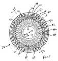
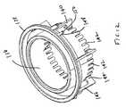
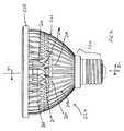
図14〜22に示されるヒートシンクアセンブリ224の実施形態に注意が喚起される。図19に最良に示されるように、ヒートシンク226は、中央通路234を有する円筒状基部232を含み、そこを通って中心線236を画定する。複数の離間配置された細長いフィン238が基部232から延在する。それぞれのフィン238は、基部232から外方に延在する下部239と、基部232の装着面232aから上方に延在する上部262とを有する。したがって、図21から理解され得るように、フィンの上部は、第1の方向Aに上方に延在し、ヒートスプレッダのフィンもまた第1の方向に延在するが、ヒートスプレッダのフィンは、第1の方向Aにさらに延在する。加えて、ヒートシンク226のフィンのいくつかは、プレート288の場所と比較して、第1の方向Aと反対である第2の方向Bに延在する。 Attention is drawn to the embodiment of the
図21に最良に示されるように、それぞれのフィン238の下部239は、基部232から半径方向に外方に延在する。それぞれの下部239は、基部232から外方に湾曲する外縁246を有する。結果として、図19の垂直チャネル248が隣接する下部239間に形成され、装着面232aの下に延在する。図示されるように、弓状片260が、基部232から離間配置される位置で隣接する下部239間に提供され、そのため外周243を有する円形リングが弓状片260および下部239によって形成される。このリングは、それぞれの垂直チャネル248を基部232の上端部252で内側セクション248aおよび外側セクション248bに分割する。 As best shown in FIG. 21, the
基部232の上端部252は、図19の内側リング254を形成するように厚くされる。等間隔に離間配置された場所で、埋め立てられた領域256は、内側リング254から外方に延在し、ヒートスプレッダ228および熱パッド(提供される場合)をヒートシンク226に取り付けるためにその中に孔258を有する固着点を提供する。一対の円形溝253a、253bが、基部232の上端部252から所定の距離で下方に延在する。 The
それぞれのフィン238の上部262は、下部239から上方に延在し、基部232から離間配置される。それぞれの上部262は、下部239に対してある角度で延在する下部セクション264と、下部セクション264から上方に延在する上部セクション266とを含む。上部セクション266および下部239は、互いに平行であるが、互いにオフセットされる。それぞれの上部262の外表面は、下部239の曲線を続ける。下部セクション264および上部セクション266の内表面265は、基部232の中心線236に対して上方かつ外方に湾曲する。隣接する上部セクション266間にチャネル270が形成される。上部セクション266の上部の外端部269で外側リング272が提供され、上部セクション266をともに接続する。ヒートシンク226の構造の結果として、フィン238によって複数のチャネル248、270が形成され、空気が基部232の底端部250からフィン238の上端部269に循環することを可能にする。 The
所望される場合、図面に示されるように、二次下部セクション274が提供され、それぞれフィン238の上部セクション266を隣接するフィン238の下部239に接続することができる。二次下部セクション274は、下部セクション264に対して、かつ上部セクション242に対して角度を成す。したがって、二次下部セクション274が提供される場合、図16に示されるように、下部239、一方のフィン238の下部セクション264および上部セクション266、ならびに隣接するフィン238の二次下部セクション274および上部セクション266によってY字型が概ね形成される。Y字型が尖った角を有して示されるが、これらの角は、U字型が形成されるように丸みを帯びる可能性があり、あるいは下部セクション266、274は、T字型が形成されるように水平である可能性もあることが理解されるべきである。 If desired, a secondary
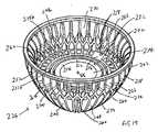
図20に示されるように、ヒートスプレッダ228は、リングの外周243の形状に概して適合する外側の円形縁290を有する薄いプレート288を含む。円形壁289が、プレート288の周囲の外縁290から上方に延在する。複数の離間配置されたフィン291が壁289から延在する。それぞれのフィン291は、壁289の高さに沿って延在する第1の部分291aと、壁289の上端部から上方かつ外方に延在する第2の部分291bとを有する。それぞれのフィン291の第2の部分291bの内表面および外表面は湾曲される。上部リング293が第2の部分291bの上端部とともに接続する。この構造の結果として、壁289の上端部と隣接するフィン291の上部291bと上部リング293との間に複数の開口292が形成される。 As shown in FIG. 20, the
一対のフランジ295(図示されるもののうちの1つのみ)が、外壁289から外方に延在し、締結具がヒートスプレッダ228をヒートシンク226に取り付けるように着座される中にそこを通って提供される貫通穴を有する。LEDアセンブリ222をヒートスプレッダ228に取り付けるためにプレート288を通って一対の貫通穴302が提供される。 A pair of flanges 295 (only one of those shown) extend outwardly from the
ヒートスプレッダ228は、熱伝導性であり、銅、アルミニウム、または高い熱伝導率を有する任意の他の材料等の材料から形成される可能性があり、この材料は、LEDアセンブリ222とヒートシンク226との間に低い熱抵抗率を提供することを促すことができ、一実施形態では、摂氏2度毎ワット(C/W)未満であり得、一実施形態では、1.5度未満であり得る。ヒートスプレッダ228のプレート288は、0.5mmを超える厚さ(上面288a(LEDアセンブリ222に隣接する)から底面(ヒートシンク226に近接する))を有する。ほとんどの用途では、高熱伝導性材料(例えば、100W/m−K超の熱伝導率を有する材料)がヒートスプレッダ228に使用されるとき、厚さ約1.2mmを超えるヒートスプレッダ228を有することに対する利点低下があり、1.5mm未満の厚さを有することは重量の観点から有益であり得ることが判明された。そのように示されたが、あるより高いワット数用途(例えば、10ワット超)では、より厚いプレート288がいくつかの利点をさらに提供する場合がある。さらに理解され得るように、ヒートスプレッダは、プレート288の前方に延在し、したがってヒートスプレッダが空洞から出口に向かって熱エネルギーを方向付けるのを促すため、ランプが凹型空洞内に装着される(例えば、ダウンライト用途)状況で改善された熱管理を提供することを促すのに有益であり得る。 The
図1〜12の実施形態で提供されるような熱パッド(図示せず)が、ヒートスプレッダ228の片側に装着され、ヒートシンク226とヒートスプレッダ228のプレート288との間に提供されてもよい。プレート288/熱パッドは、基部232の上端部252および弓状片260に着座され得る。フィン291は上部262に近接するが、そこから離間配置され、そのため隣接するフィン291と円形壁289と上部262との間に図21および22参照のチャネル297が形成される。ヒートスプレッダ228の外側リング293は、それを少なくとも部分的に塞ぐようにヒートシンク226の外側リング272に着座し、外側リング293は好ましくは、外側リング272が着座する凹部301を有する。所望される場合、外側リング272と外側リング293との間の接点に沿って熱ガスケットも提供され、それらの間に良好な熱接続を提供することを促すことができる。 A thermal pad (not shown) as provided in the embodiment of FIGS. 1-12 may be mounted on one side of the
図17のLEDアセンブリ222は、LEDモジュール314と、LEDダイを支持し、ボード320を含み得る基板315上に提供される陽極316および陰極318と、基部アセンブリ322とを含む。LEDモジュール314は、絶縁基部と、基部上に着座されるLEDと、基部上に着座され、LEDを覆うLEDカバー326とを含む。LEDは、単一LEDまたはアレイであってもよい。基部アセンブリ322は、ブロック322a内に電子部品(調光に対処するAC/DC変換電子部品など)を収容し、ブロック322aは、熱伝導性だが電気的絶縁材料内に注封されることによって支持される様々な所望の制御および変換回路であり得る。陽極316および陰極318は、LEDに接続され、基部を通って延在し、ボード320に接続する。ボード320は、電子部品も支持することができ、基部アセンブリ322に、かつ陽極316および陰極318に電気的に結合される。ボード320上の電子部品は、AC/DC変換をLEDモジュール314に提供してもよい。 The
図21に示されるように、LEDモジュール314は、ヒートスプレッダ228のプレート288の上面に着座する。したがって、ヒートスプレッダ228は、LEDモジュール314の下面とヒートシンク226との間に位置決めされる。ヒートスプレッダ228は、LEDがヒートスプレッダ228に熱的に結合されるようにLEDモジュール314の下面に隣接する。 As shown in FIG. 21, the
1つ以上のLEDがLEDモジュール314で使用され、LEDアレイを提供することができ、LED(複数可)は、交流または直流電力によって作動されるように設計され得る。交流LEDを使用する利点は、従来のAC線間電圧を直流電圧に変換する必要性がないことである。これは、電力変換器回路が、高価になる傾向があるか、またはLED自体が持続することができる限り、持続する可能性が高くないかのいずれかであるときに費用が重要な推進力である場合に有利であり得る。したがって、LED器具から期待される30,000〜70,000時間を得るために、交流LEDの使用は有益であり得る。しかしながら、外部AC/DC変換がある用途では(例えば、線間電圧を有することが望ましくない用途では)、または長期持続するように推進力が構成される状況では、直流LEDは、既存の直流LEDが優れた性能を有する傾向があるときに利点を提供してもよい。調光が望ましい場合、制御回路が必要とされてもよく、このような状況では、直流LEDの使用は、費用効率が高くなる可能性が高い。LEDアレイがヒートスプレッダまたはヒートシンクに係合するLEDアレイと嵌合接点との間の低い熱抵抗のために構成される場合、この系統はより効率的になる傾向があることに留意すべきである。Bridgeluxから入手可能であるなどのLEDアレイが好適である(一実施形態では、例えば、LEDアレイとヒートスプレッダとの間の熱抵抗が摂氏2度毎ワット未満であり得、一実施形態では、高い熱効率のLEDアレイが使用される場合、摂氏1度毎ワット未満であり得る)。 One or more LEDs can be used in the
LEDアセンブリ222は、誘電ハウジング332と、ハウジング332内に装着される反射体334と、反射体334の上端部に装着されるレンズカバー335とをさらに含む。図17に最良に示されるように、ハウジング332は、外側の円形壁338と、壁338の上端部から内方に延在する上壁339とから形成される。壁338の下端部は、ハウジング332をヒートスプレッダ228内の好適な開口341の中に位置決めおよび接続するためのスナップ式のアーム339等のコネクタを有する。ヒートシンクが以下に記載されるようにプラスチックおよび熱コーティングを含む複合構造で形成される場合、ハウジング332は、ヒートシンク226で一体的に形成され、ハウジング332は、ヒートシンク226がツーショット成形によって形成されるときにヒートシンク226の非めっき可能な第1のショットで形成され得る。 The
反射体334は、下部開口および上部開口を有する開放型壁によって形成される。下部開口は、LEDカバー326のような形をしている。壁は、角度を成した内表面を含み、その上端部でその最大直径を有し、内方に先細りになる。反射体334は、好適な手段によってLEDモジュール314の基部上に装着され、そのためLEDカバー326が反射体の下部開口内に位置決めされる。壁の上端部は、照明面を提供する。反射体334は熱伝導性であり得る(例えば、熱伝導性めっきによって提供され得る)。レンズ335は、上部開口内に固定される。ハウジング332は反射体334を取り囲む。 The
基部アセンブリ322は、ボード320に電気的に接続される(一実施形態では、以下に示されるように、ブロック322a内に回路を含む)。基部アセンブリ322は、ねじ込み口金328と、ヒートシンク226からねじ込み口金328を電気的に絶縁する誘電体リング330とを含む。誘電体リング330は、バヨネット取り付け等の好適な接続によってともに着脱可能に結合される2つの構成要素で形成され得る。ブロック322a(基部アセンブリ322内に位置決めされるように好適な任意の形状であり得る)が重複として図示されるが、実際には、ランプの望ましいアセンブリを可能にしながら必要とされる許容範囲に対処するのに好適であるより一層のライン間適合を提供するように構成され、位置決めされ得ることに留意すべきである。
LEDモジュール314内のLEDが駆動されるとき、LEDを通過する電流は、ヒートスプレッダ228に通される熱を発生させる。次に、熱はヒートシンク226まで通り、熱がフィン238まで外方に広がる。開口292およびチャネル248/270/297は、熱を伝導する効率的な伝熱経路を提供し、そのため熱がフィン238の長さにわたって放出され得る。結果として、めっきプラスチックがヒートシンク226に使用されるとき、熱がヒートシンク226全体にわたって効率的に放出される。下部セクション264および二次下部セクション274は、そこを通る開口を有して示されないが、開口(ヒートシンクアセンブリ26の開口68、76と同様)がこれらのセクション264、274のうちの1つまたは両方を通って提供され得ることを理解されるべきである。 When the LEDs in the
図23は、LEDモジュール314に組み込まれる熱パックまたは相変化パッド400を示す。熱パック/相変化パッド400は、LEDモジュール314の基部の下面に提供され、LEDモジュール314に統合され、熱伝導性エポキシによってそれに取り付けられる導電素子であってもよい。代替的な実施形態では、熱パック/相変化パッド400は、熱伝導性エポキシまたははんだなど(それに限定しない)、調合された導電材料であり得る。LEDモジュール314は、ヒートスプレッダ228のプレート288の上面に着座し、そのため熱パック/相変化パッド400がプレート288に接触し、LEDがヒートスプレッダ228に熱的に結合される。 FIG. 23 shows a heat pack or
熱パック400およびヒートスプレッダ228は、十分に高い熱導電率を有するように、ランプ220の熱抵抗率に実質的に無関係であるように、構成され得る。例えば、熱パック400は、ヒートスプレッダ228にはんだ付けされることができ、はんだが15W/mK超の熱伝導率を有する傾向があり、かつ比較的薄く積層されるとき、それは、熱をLEDから離れて移動させている重要な因子でない傾向がある。さらに、熱パック400およびヒートスプレッダ228が高い熱伝導率(典型的に50W/mK超)を有する材料で作製される傾向があるとき、熱パック400とヒートスプレッダ228との間にほとんど熱抵抗がない傾向がある。 The
それぞれの実施形態では、ヒートシンク26、226は、めっきプラスチックで形成され得る。ヒートシンク26、226上のめっきは、めっきプラスチックで一般的に使用される従来のめっきであってもよく、ヒートシンク26、226は、ツーショット成形プロセスによって形成されてもよい。ヒートシンク26、226がアルミニウム片として形成され得ることも想定される。アルミニウムの利点は、熱がヒートシンク26、226にわたって容易に伝導することであり、したがって熱源から熱を奪うように比較的単純にする。アルミニウムがその許容可能な伝熱性による良好なヒートシンクとして機能するが、アルミニウムは、複雑な形状に形成するのがより困難であり、したがってアルミニウムで可能となる設計は多少限定される。さらに、アルミニウムは、導体として機能し、したがってさらなる電気的絶縁を必要としてもよい。めっきプラスチックは、熱を伝導するために使用され、めっきが熱源から離れて表面に沿って熱を移動させるために使用され得る。望ましい性能レベルが達成されるべきである場合にめっきが伝熱の一次経路になる傾向があるため、めっきプラスチックが使用されるときに熱源から熱を奪うことはより複雑である。したがって、めっきプラスチックを効率的に使用するために、アルミニウムのヒートシンクに十分であるような単純なヒートシンク設計が所望の性能を提供するのに適切でなくてもよいことが判明された。図示された設計は、ヒートスプレッダと嵌合するヒートシンクの内表面と垂直チャネルの外表面との間に多くの垂直チャネル48、248を提供し、1つ以上の溝(図示されるように、円形溝253a、253b)と組み合わせて、ヒートシンクは、所望されるように成形され得る多くの熱チャネルを提供し、熱エネルギーが複合めっきプラスチック構成でヒートシンクの外表面に容易に通過することを可能にする。さらに、めっきプラスチック設計を使用して、ヒートシンク26、226では、LEDアセンブリ22、22aに対する支持および放熱の両方を提供することができる。ヒートシンクおよびヒートスプレッダのための他の選択肢としては、鋳型で形成され得るガラス状金属材料の使用が挙げられるが、このような材料は重くなる傾向があり、したがって製造の容易さが重量の検討事項と平衡を保つ必要がある。 In each embodiment, the heat sinks 26, 226 may be formed of plated plastic. The plating on the heat sinks 26, 226 may be conventional plating commonly used with plated plastics, and the heat sinks 26, 226 may be formed by a two-shot molding process. It is envisioned that the heat sinks 26, 226 may be formed as aluminum pieces. The advantage of aluminum is that heat is easily conducted across the heat sinks 26, 226, thus making it relatively simple to take heat away from the heat source. Although aluminum functions as a good heat sink due to its acceptable heat transfer properties, aluminum is more difficult to form into complex shapes, and thus the designs that are possible with aluminum are somewhat limited. Furthermore, aluminum functions as a conductor and may therefore require further electrical insulation. Plated plastic is used to conduct heat and the plating can be used to move heat away from the heat source along the surface. Since plating tends to be the primary path of heat transfer when the desired performance level is to be achieved, it is more complex to remove heat from the heat source when plated plastic is used. Thus, it has been found that a simple heat sink design, such as sufficient for an aluminum heat sink, may not be appropriate to provide the desired performance in order to efficiently use plated plastic. The illustrated design provides a number of
したがって、理解され得るように、熱負荷および他の設計の検討事項に応じて、他の材料もまたヒートシンク26、226に使用されてもよい。例えば、5ケルビン毎メートルワットを超える熱伝導率を有する絶縁材料がある用途に使用される可能性があり、20ケルビン毎メートルワットを超える熱伝導率を有する高性能絶縁材料が幅広い用途に有益であろう。しかしながら、現在まで、このような熱伝導率を有する絶縁材料は比較的高価であり、したがってそれらが機能的に望ましいとしても商業的に望ましいとされない場合がある。しかしながら、ランプ20、220の構築の結果として、ランプ20、220の高さは、500ルーメンを超える出力を可能にし、かつLEDアレイとヒートシンクの外表面との間に2度C/ワット未満の温度上昇(一実施形態では、1.5C/W未満であってもよい)を提供しながら、90mm未満であり得る。ヒートシンクの温度が完全に均一であると予測されないため、温度上昇は平均として決定され得る。一実施形態では、ランプの高さは90mm未満であり得るが、15ワット未満の電力を必要とし、かつ2C/W未満、好ましくは1.5C/W未満であるLEDアレイとヒートシンクの外表面との間の熱抵抗を有しながら、出力は650ルーメンを超え得る。 Thus, as can be appreciated, other materials may also be used for the heat sinks 26, 226, depending on the thermal load and other design considerations. For example, an insulating material having a thermal conductivity greater than 5 Kelvin per meter watt may be used in some applications, and a high performance insulating material having a thermal conductivity greater than 20 Kelvin per meter watt may be beneficial for a wide range of applications. I will. To date, however, insulating materials having such thermal conductivity are relatively expensive and therefore may not be commercially desirable even though they are functionally desirable. However, as a result of the construction of the
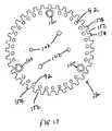
図24に示されるように、ヒートシンク26は、弓状片60を取り除くように改良され、そのためチャネル48a、48bが組み合わされ得る(ヒートシンク26の弓状片60が同様にチャネル48a、48bを組み合わせるように取り除かれ得る)。この改良されたヒートシンク26では、ヒートスプレッダ28の開口92、96、98の第1の列、第2の列、および第3の列は、それぞれの組み合わされたチャネル48a/48bの上に着座する。 As shown in FIG. 24, the
したがって、理解され得るように、ヒートスプレッダ228の第1の表面288aは、LEDアレイを支持する。それ故に、LEDアレイは、第1の方向Aに光を方向付けるように構成される。ヒートスプレッダ228は、第1の方向に第1の表面から延在するフィン291をさらに有する(したがって熱エネルギーが第1の方向に方向付けられることを可能にする)。ヒートシンク226は、熱エネルギーが第2の方向Bにヒートシンクの表面に沿って方向付けられることを可能にする熱チャネルを有する。それ故に、図示された設計は、双方向の熱転写を提供する。理解され得るように、ランプがソケット(缶型照明に慣習的であるような)内に装着される場合、フィン291は、ランプから離れて熱転写を改善するように缶の開口部により近い表面積を提供するのを促す。 Thus, as can be appreciated, the first surface 288a of the
ある用途では、LEDからさらにより効率的に熱が奪われ得るように、蒸気チャンバを含むヒートスプレッダまたはヒートシンクを提供することが望ましくあってもよいことに留意すべきである。このような用途としては、高出力のLEDアレイが挙げられる。しかしながら、他の用途では、高い熱伝導率を有する材料が十分であってもよい。ヒートシンク/ヒートスプレッダとともに使用するための蒸気チャンバは、当該技術分野において既知であり、米国特許第5,550,531号および同第6,639,799号に例として示され、その開示全体が参照により本明細書に組み込まれる。 It should be noted that in some applications it may be desirable to provide a heat spreader or heat sink that includes a vapor chamber so that heat can be removed from the LEDs even more efficiently. Such applications include high power LED arrays. However, for other applications, a material with high thermal conductivity may be sufficient. Steam chambers for use with heat sinks / heat spreaders are known in the art and are shown by way of example in US Pat. Nos. 5,550,531 and 6,639,799, the entire disclosure of which is hereby incorporated by reference Incorporated herein.
一般的に、経路に沿った熱抵抗がそれぞれの構成要素の熱抵抗と見なされ、接点が他の構成要素および同一経路の接点と直列であり得ることに留意すべきである。したがって、所望の全熱抵抗を提供するために、それぞれの構成要素が別々に最適化され得る。直列特質により、非効率である1つの構成要素を選択することは、全系統を意図されるように動かさないようにする可能性があることに留意すべきである。したがって、それぞれの構成要素が意図された性能レベルに最適化されることを確実にすることが有益であり得る。さらに、所望される場合、接点を避けるように(それぞれの接点が熱抵抗を増大する傾向があるように)ある構成要素が一体にされ得る。例えば、ヒートスプレッダおよびLEDモジュールの基部は統合され得る(例えば、LEDアレイはヒートスプレッダに相当するより大きな基部に装着され得る)。 It should be noted that in general, the thermal resistance along the path is considered the thermal resistance of each component, and the contacts can be in series with other components and contacts of the same path. Thus, each component can be optimized separately to provide the desired total thermal resistance. It should be noted that due to the series nature, selecting one component that is inefficient may prevent the entire system from moving as intended. Thus, it can be beneficial to ensure that each component is optimized to the intended performance level. In addition, if desired, certain components can be combined to avoid contacts (so that each contact tends to increase thermal resistance). For example, the base of the heat spreader and the LED module can be integrated (eg, the LED array can be mounted on a larger base corresponding to the heat spreader).
ある特定の好ましい実施形態が図示され、記載されるが、添付の特許請求の範囲の趣旨および範囲から逸脱することなく、当業者は図示された実施形態の様々な修正を案出することができると想定される。 While certain preferred embodiments have been illustrated and described, those skilled in the art can devise various modifications of the illustrated embodiments without departing from the spirit and scope of the appended claims. It is assumed.
Claims (19)
Translated fromJapanese前記第1の表面に熱的に結合される発光ダイオード(LED)アレイと、
表面を有する基部と、該基部から外方に延在する複数のフィンとを含むヒートシンクであって、前記複数のフィンの上部が、前記基部から第1の方向に延在し、前記複数のフィンの下部が、前記基部から第2の方向に延在する、ヒートシンクと、を備え、熱チャネルが前記基部の表面をフィンの下部と結合する、ランプ。A conductive heat spreader having a first surface and a plurality of fins positioned in a first direction from the first surface;
A light emitting diode (LED) array thermally coupled to the first surface;
A heat sink including a base having a surface and a plurality of fins extending outward from the base, wherein upper portions of the plurality of fins extend from the base in a first direction, and the plurality of fins And a heat sink extending in a second direction from the base, wherein a heat channel couples the surface of the base to the bottom of the fin.
プレート様形状を有する本体と、
該本体から上方に延在する複数の離間配置されたフィンと、を備える、ヒートスプレッダ。A conductive heat spreader,
A body having a plate-like shape;
And a plurality of spaced apart fins extending upwardly from the body.
プレートおよび第1の組のフィンを有する本体を有するヒートスプレッダであって、前記フィンは、離間配置され、前記プレートから第1の方向に延在する、ヒートスプレッダと、
前記ヒートスプレッダに熱的に結合されるヒートシンクであって、前記ヒートシンクは、第2の組のフィンを有し、前記第2の組のフィンの第1の部分が、前記第1の方向に延在し、前記第2の組のフィンの第2の部分が、前記第1の方向と反対の第2の方向に延在する、ヒートシンクと、を備える、熱系統。A thermal system,
A heat spreader having a body having a plate and a first set of fins, the fins being spaced apart and extending in a first direction from the plate;
A heat sink thermally coupled to the heat spreader, the heat sink having a second set of fins, wherein a first portion of the second set of fins extends in the first direction. And a heat sink, wherein a second portion of the second set of fins extends in a second direction opposite to the first direction.
Applications Claiming Priority (3)
| Application Number | Priority Date | Filing Date | Title |
|---|---|---|---|
| US201161474077P | 2011-04-11 | 2011-04-11 | |
| US61/474,077 | 2011-04-11 | ||
| PCT/US2012/032980WO2012142068A2 (en) | 2011-04-11 | 2012-04-11 | Led lamp |
Publications (1)
| Publication Number | Publication Date |
|---|---|
| JP2014516459Atrue JP2014516459A (en) | 2014-07-10 |
Family
ID=47009927
Family Applications (1)
| Application Number | Title | Priority Date | Filing Date |
|---|---|---|---|
| JP2014505228APendingJP2014516459A (en) | 2011-04-11 | 2012-04-11 | LED lamp |
Country Status (5)
| Country | Link |
|---|---|
| US (1) | US9335101B2 (en) |
| JP (1) | JP2014516459A (en) |
| CN (1) | CN103492802B (en) |
| TW (2) | TWM441089U (en) |
| WO (1) | WO2012142068A2 (en) |
Cited By (1)
| Publication number | Priority date | Publication date | Assignee | Title |
|---|---|---|---|---|
| JP2016029604A (en)* | 2014-07-25 | 2016-03-03 | 日立アプライアンス株式会社 | Lighting device |
Families Citing this family (19)
| Publication number | Priority date | Publication date | Assignee | Title |
|---|---|---|---|---|
| CN103244926A (en)* | 2012-02-14 | 2013-08-14 | 欧司朗股份有限公司 | Radiating device for lighting device, lighting device and lamp |
| CN103423721B (en)* | 2012-05-14 | 2018-02-13 | 欧司朗股份有限公司 | Heat abstractor and the lighting device with the heat abstractor |
| EP2885577B1 (en) | 2012-08-17 | 2017-03-29 | Philips Lighting Holding B.V. | Heat dissipation structure with splitted chimney structure |
| RU2659585C2 (en)* | 2012-09-18 | 2018-07-03 | Филипс Лайтинг Холдинг Б.В. | Lamp with heat sink |
| EP2725295B1 (en)* | 2012-10-26 | 2017-11-08 | LG Electronics Inc. | Lighting apparatus |
| CN103115342B (en)* | 2013-02-28 | 2016-03-16 | 成都易明半导体有限公司 | LED lamp radiator and LED lamp |
| US9052093B2 (en)* | 2013-03-14 | 2015-06-09 | Cree, Inc. | LED lamp and heat sink |
| KR101696722B1 (en)* | 2014-12-18 | 2017-02-01 | 엘지전자 주식회사 | Lighting device |
| CN105276550B (en)* | 2015-11-05 | 2020-08-25 | 漳州立达信光电子科技有限公司 | heat sink light cup |
| CN106678566A (en)* | 2015-11-09 | 2017-05-17 | 常州阿拉丁照明电器有限公司 | No-drive LED reflector lamp |
| CN105423249B (en)* | 2015-12-20 | 2019-03-29 | 西安智海电力科技有限公司 | The power storehouse wiring construction of Fast-Maintenance LED lamp |
| US10767849B2 (en)* | 2016-04-25 | 2020-09-08 | Shat-R-Shield, Inc. | LED luminaire |
| CN108253327B (en) | 2016-12-27 | 2021-06-15 | 通用电气照明解决方案有限公司 | Lamp and luminaire |
| KR101934033B1 (en)* | 2017-06-07 | 2018-12-31 | 이노컴퍼니(주) | LED floodlight having reinforced heat radiant function |
| CN111520653B (en)* | 2017-12-08 | 2022-03-11 | 嘉兴山蒲照明电器有限公司 | an LED light |
| EP3846751B1 (en)* | 2018-09-04 | 2024-12-18 | AMO Development, LLC | Narrow angle illumination ring for ophthalmic surgical laser system |
| US12092399B2 (en)* | 2020-07-14 | 2024-09-17 | Raytheon Company | Chimney cooler design for rugged maximum free convection heat transfer with minimum footprint |
| EP4569261A1 (en)* | 2022-08-08 | 2025-06-18 | Signify Holding B.V. | Light fixture heat sink with passive air flow |
| WO2024179950A1 (en) | 2023-03-02 | 2024-09-06 | Signify Holding B.V. | Heat spreader fixation |
Citations (3)
| Publication number | Priority date | Publication date | Assignee | Title |
|---|---|---|---|---|
| JP2010073569A (en)* | 2008-09-19 | 2010-04-02 | Toshiba Lighting & Technology Corp | Lamp device and illumination fixture |
| JP2010114060A (en)* | 2008-11-06 | 2010-05-20 | Taiyo Denki Kk | Led lighting fixture |
| JP3164817U (en)* | 2010-10-06 | 2010-12-16 | 東貝光電科技股▲ふん▼有限公司 | LED bulb |
Family Cites Families (19)
| Publication number | Priority date | Publication date | Assignee | Title |
|---|---|---|---|---|
| US6787999B2 (en) | 2002-10-03 | 2004-09-07 | Gelcore, Llc | LED-based modular lamp |
| US7679096B1 (en)* | 2003-08-21 | 2010-03-16 | Opto Technology, Inc. | Integrated LED heat sink |
| US7549774B2 (en)* | 2007-04-24 | 2009-06-23 | Hong Kuan Technology Co., Ltd. | LED lamp with plural radially arranged heat sinks |
| CN101368719B (en)* | 2007-08-13 | 2011-07-06 | 太一节能系统股份有限公司 | LED lamps |
| US20100242519A1 (en)* | 2007-12-07 | 2010-09-30 | Osram Gesellschaft Mit Beschraenkter Haftung | Heat sink and lighting device comprising a heat sink |
| WO2009071111A1 (en)* | 2007-12-07 | 2009-06-11 | Osram Gesellschaft mit beschränkter Haftung | Heat sink and lighting device comprising a heat sink |
| US20090296387A1 (en)* | 2008-05-27 | 2009-12-03 | Sea Gull Lighting Products, Llc | Led retrofit light engine |
| US7748870B2 (en) | 2008-06-03 | 2010-07-06 | Li-Hong Technological Co., Ltd. | LED lamp bulb structure |
| CN201237110Y (en) | 2008-07-15 | 2009-05-13 | 东莞市贻嘉光电科技有限公司 | LED (light-emitting diode) spotlight |
| CN101660735B (en)* | 2008-08-27 | 2012-07-04 | 富准精密工业(深圳)有限公司 | Light emitting diode (LED) lamp |
| US8240885B2 (en)* | 2008-11-18 | 2012-08-14 | Abl Ip Holding Llc | Thermal management of LED lighting systems |
| CN201322284Y (en) | 2008-12-12 | 2009-10-07 | 东莞市贻嘉光电科技有限公司 | Heat dissipation device of LED spotlight |
| KR101052894B1 (en) | 2009-05-19 | 2011-07-29 | 주식회사 포트론 | Heat Sink and LED Lamp for LED Lamp |
| KR100927114B1 (en)* | 2009-05-20 | 2009-11-18 | 주식회사 파인테크닉스 | LED lamp for halogen lamp |
| JP5354191B2 (en)* | 2009-06-30 | 2013-11-27 | 東芝ライテック株式会社 | Light bulb shaped lamp and lighting equipment |
| TW201104156A (en)* | 2009-07-28 | 2011-02-01 | Young Dong Tech Co Ltd | Light emitting diode lighting device |
| CN101846260B (en)* | 2010-06-04 | 2014-07-09 | 东莞市翔光光电科技有限公司 | LED illumination bulb and heat dissipation seat thereof |
| TWM401101U (en) | 2010-09-21 | 2011-04-01 | Unity Opto Technology Co Ltd | LED illumination lamp |
| US8618742B2 (en)* | 2011-02-11 | 2013-12-31 | Soraa, Inc. | Illumination source and manufacturing methods |
- 2012
- 2012-04-11TWTW101206559Upatent/TWM441089U/enunknown
- 2012-04-11TWTW101112795Apatent/TWI506226B/ennot_activeIP Right Cessation
- 2012-04-11WOPCT/US2012/032980patent/WO2012142068A2/enactiveApplication Filing
- 2012-04-11USUS14/110,654patent/US9335101B2/ennot_activeExpired - Fee Related
- 2012-04-11JPJP2014505228Apatent/JP2014516459A/enactivePending
- 2012-04-11CNCN201280018091.0Apatent/CN103492802B/ennot_activeExpired - Fee Related
Patent Citations (3)
| Publication number | Priority date | Publication date | Assignee | Title |
|---|---|---|---|---|
| JP2010073569A (en)* | 2008-09-19 | 2010-04-02 | Toshiba Lighting & Technology Corp | Lamp device and illumination fixture |
| JP2010114060A (en)* | 2008-11-06 | 2010-05-20 | Taiyo Denki Kk | Led lighting fixture |
| JP3164817U (en)* | 2010-10-06 | 2010-12-16 | 東貝光電科技股▲ふん▼有限公司 | LED bulb |
Cited By (1)
| Publication number | Priority date | Publication date | Assignee | Title |
|---|---|---|---|---|
| JP2016029604A (en)* | 2014-07-25 | 2016-03-03 | 日立アプライアンス株式会社 | Lighting device |
Also Published As
| Publication number | Publication date |
|---|---|
| CN103492802A (en) | 2014-01-01 |
| TW201312045A (en) | 2013-03-16 |
| US9335101B2 (en) | 2016-05-10 |
| TWI506226B (en) | 2015-11-01 |
| US20140055997A1 (en) | 2014-02-27 |
| CN103492802B (en) | 2018-06-05 |
| WO2012142068A3 (en) | 2012-12-27 |
| WO2012142068A2 (en) | 2012-10-18 |
| TWM441089U (en) | 2012-11-11 |
Similar Documents
| Publication | Publication Date | Title |
|---|---|---|
| JP2014516459A (en) | LED lamp | |
| US9791140B2 (en) | Light module | |
| US9052093B2 (en) | LED lamp and heat sink | |
| US9395074B2 (en) | LED lamp with LED assembly on a heat sink tower | |
| US9068701B2 (en) | Lamp structure with remote LED light source | |
| US9383088B2 (en) | Solid state lighting device having a packaged heat spreader | |
| US20130279175A1 (en) | Led lamp | |
| WO2013154931A1 (en) | Led lamp | |
| US8905601B2 (en) | Lighting apparatus having a thermal insulator | |
| WO2014179519A2 (en) | Led lamp | |
| US20110298352A1 (en) | Led lamp and methods of manufacturing the same | |
| CN201096280Y (en) | Lamp fitting | |
| KR20140053520A (en) | Lighting apparatus | |
| KR200462430Y1 (en) | Led lighter | |
| WO2011124386A1 (en) | Heat dissipation structure, led lamp and method of manufacturing a heat dissipation structure | |
| KR20110139466A (en) | LED lighting fixture and manufacturing method | |
| JP2011150926A (en) | High-efficiency type led lamp | |
| US8350450B2 (en) | LED lamp | |
| JP3160879U (en) | High efficiency LED lamp | |
| CN201100542Y (en) | lighting fixtures | |
| TWM394427U (en) | Structure of electricity/heat separated LED bulb module | |
| JP2014207172A (en) | Lighting device | |
| WO2011155851A1 (en) | Led lamp and method of manufacturing the same | |
| KR20150009003A (en) | Led lamp | |
| TW201017037A (en) | Light bar apparatus and recessed light using the same |
Legal Events
| Date | Code | Title | Description |
|---|---|---|---|
| A131 | Notification of reasons for refusal | Free format text:JAPANESE INTERMEDIATE CODE: A131 Effective date:20140930 | |
| A601 | Written request for extension of time | Free format text:JAPANESE INTERMEDIATE CODE: A601 Effective date:20141226 | |
| A601 | Written request for extension of time | Free format text:JAPANESE INTERMEDIATE CODE: A601 Effective date:20150129 | |
| A601 | Written request for extension of time | Free format text:JAPANESE INTERMEDIATE CODE: A601 Effective date:20150227 | |
| A02 | Decision of refusal | Free format text:JAPANESE INTERMEDIATE CODE: A02 Effective date:20150630 |