JP2014515624A - Syringe head, extrusion unit, and syringe formed therefrom - Google Patents
Syringe head, extrusion unit, and syringe formed therefromDownload PDFInfo
- Publication number
- JP2014515624A JP2014515624AJP2013554746AJP2013554746AJP2014515624AJP 2014515624 AJP2014515624 AJP 2014515624AJP 2013554746 AJP2013554746 AJP 2013554746AJP 2013554746 AJP2013554746 AJP 2013554746AJP 2014515624 AJP2014515624 AJP 2014515624A
- Authority
- JP
- Japan
- Prior art keywords
- syringe
- guide
- coupling
- locking
- syringe barrel
- Prior art date
- Legal status (The legal status is an assumption and is not a legal conclusion. Google has not performed a legal analysis and makes no representation as to the accuracy of the status listed.)
- Pending
Links
Images


Classifications
- A—HUMAN NECESSITIES
- A61—MEDICAL OR VETERINARY SCIENCE; HYGIENE
- A61M—DEVICES FOR INTRODUCING MEDIA INTO, OR ONTO, THE BODY; DEVICES FOR TRANSDUCING BODY MEDIA OR FOR TAKING MEDIA FROM THE BODY; DEVICES FOR PRODUCING OR ENDING SLEEP OR STUPOR
- A61M5/00—Devices for bringing media into the body in a subcutaneous, intra-vascular or intramuscular way; Accessories therefor, e.g. filling or cleaning devices, arm-rests
- A61M5/178—Syringes
- A61M5/31—Details
- A61M5/32—Needles; Details of needles pertaining to their connection with syringe or hub; Accessories for bringing the needle into, or holding the needle on, the body; Devices for protection of needles
- A61M5/34—Constructions for connecting the needle, e.g. to syringe nozzle or needle hub
- A61M5/347—Constructions for connecting the needle, e.g. to syringe nozzle or needle hub rotatable, e.g. bayonet or screw
- A—HUMAN NECESSITIES
- A61—MEDICAL OR VETERINARY SCIENCE; HYGIENE
- A61M—DEVICES FOR INTRODUCING MEDIA INTO, OR ONTO, THE BODY; DEVICES FOR TRANSDUCING BODY MEDIA OR FOR TAKING MEDIA FROM THE BODY; DEVICES FOR PRODUCING OR ENDING SLEEP OR STUPOR
- A61M5/00—Devices for bringing media into the body in a subcutaneous, intra-vascular or intramuscular way; Accessories therefor, e.g. filling or cleaning devices, arm-rests
- A61M5/178—Syringes
- A61M5/24—Ampoule syringes, i.e. syringes with needle for use in combination with replaceable ampoules or carpules, e.g. automatic
- A61M5/2455—Ampoule syringes, i.e. syringes with needle for use in combination with replaceable ampoules or carpules, e.g. automatic with sealing means to be broken or opened
- A61M5/2466—Ampoule syringes, i.e. syringes with needle for use in combination with replaceable ampoules or carpules, e.g. automatic with sealing means to be broken or opened by piercing without internal pressure increase
- A—HUMAN NECESSITIES
- A61—MEDICAL OR VETERINARY SCIENCE; HYGIENE
- A61M—DEVICES FOR INTRODUCING MEDIA INTO, OR ONTO, THE BODY; DEVICES FOR TRANSDUCING BODY MEDIA OR FOR TAKING MEDIA FROM THE BODY; DEVICES FOR PRODUCING OR ENDING SLEEP OR STUPOR
- A61M5/00—Devices for bringing media into the body in a subcutaneous, intra-vascular or intramuscular way; Accessories therefor, e.g. filling or cleaning devices, arm-rests
- A61M5/178—Syringes
- A61M5/28—Syringe ampoules or carpules, i.e. ampoules or carpules provided with a needle
- A61M5/285—Syringe ampoules or carpules, i.e. ampoules or carpules provided with a needle with sealing means to be broken or opened
- A61M5/288—Syringe ampoules or carpules, i.e. ampoules or carpules provided with a needle with sealing means to be broken or opened by piercing without internal pressure increase
- A—HUMAN NECESSITIES
- A61—MEDICAL OR VETERINARY SCIENCE; HYGIENE
- A61M—DEVICES FOR INTRODUCING MEDIA INTO, OR ONTO, THE BODY; DEVICES FOR TRANSDUCING BODY MEDIA OR FOR TAKING MEDIA FROM THE BODY; DEVICES FOR PRODUCING OR ENDING SLEEP OR STUPOR
- A61M5/00—Devices for bringing media into the body in a subcutaneous, intra-vascular or intramuscular way; Accessories therefor, e.g. filling or cleaning devices, arm-rests
- A61M5/178—Syringes
- A61M5/31—Details
- A61M5/32—Needles; Details of needles pertaining to their connection with syringe or hub; Accessories for bringing the needle into, or holding the needle on, the body; Devices for protection of needles
- A61M5/3205—Apparatus for removing or disposing of used needles or syringes, e.g. containers; Means for protection against accidental injuries from used needles
- A61M5/321—Means for protection against accidental injuries by used needles
- A61M5/322—Retractable needles, i.e. disconnected from and withdrawn into the syringe barrel by the piston
- A61M5/3234—Fully automatic needle retraction, i.e. in which triggering of the needle does not require a deliberate action by the user
- A—HUMAN NECESSITIES
- A61—MEDICAL OR VETERINARY SCIENCE; HYGIENE
- A61M—DEVICES FOR INTRODUCING MEDIA INTO, OR ONTO, THE BODY; DEVICES FOR TRANSDUCING BODY MEDIA OR FOR TAKING MEDIA FROM THE BODY; DEVICES FOR PRODUCING OR ENDING SLEEP OR STUPOR
- A61M5/00—Devices for bringing media into the body in a subcutaneous, intra-vascular or intramuscular way; Accessories therefor, e.g. filling or cleaning devices, arm-rests
- A61M5/178—Syringes
- A61M5/24—Ampoule syringes, i.e. syringes with needle for use in combination with replaceable ampoules or carpules, e.g. automatic
- A61M5/2455—Ampoule syringes, i.e. syringes with needle for use in combination with replaceable ampoules or carpules, e.g. automatic with sealing means to be broken or opened
- A61M5/2466—Ampoule syringes, i.e. syringes with needle for use in combination with replaceable ampoules or carpules, e.g. automatic with sealing means to be broken or opened by piercing without internal pressure increase
- A61M2005/2474—Ampoule syringes, i.e. syringes with needle for use in combination with replaceable ampoules or carpules, e.g. automatic with sealing means to be broken or opened by piercing without internal pressure increase with movable piercing means, e.g. ampoule remains fixed or steady
- A—HUMAN NECESSITIES
- A61—MEDICAL OR VETERINARY SCIENCE; HYGIENE
- A61M—DEVICES FOR INTRODUCING MEDIA INTO, OR ONTO, THE BODY; DEVICES FOR TRANSDUCING BODY MEDIA OR FOR TAKING MEDIA FROM THE BODY; DEVICES FOR PRODUCING OR ENDING SLEEP OR STUPOR
- A61M5/00—Devices for bringing media into the body in a subcutaneous, intra-vascular or intramuscular way; Accessories therefor, e.g. filling or cleaning devices, arm-rests
- A61M5/178—Syringes
- A61M5/31—Details
- A61M2005/3117—Means preventing contamination of the medicament compartment of a syringe
- A61M2005/3118—Means preventing contamination of the medicament compartment of a syringe via the distal end of a syringe, i.e. syringe end for mounting a needle cannula
- A61M2005/312—Means preventing contamination of the medicament compartment of a syringe via the distal end of a syringe, i.e. syringe end for mounting a needle cannula comprising sealing means, e.g. severable caps, to be removed prior to injection by, e.g. tearing or twisting
- A—HUMAN NECESSITIES
- A61—MEDICAL OR VETERINARY SCIENCE; HYGIENE
- A61M—DEVICES FOR INTRODUCING MEDIA INTO, OR ONTO, THE BODY; DEVICES FOR TRANSDUCING BODY MEDIA OR FOR TAKING MEDIA FROM THE BODY; DEVICES FOR PRODUCING OR ENDING SLEEP OR STUPOR
- A61M5/00—Devices for bringing media into the body in a subcutaneous, intra-vascular or intramuscular way; Accessories therefor, e.g. filling or cleaning devices, arm-rests
- A61M5/178—Syringes
- A61M5/31—Details
- A61M5/3129—Syringe barrels
- A61M5/3137—Specially designed finger grip means, e.g. for easy manipulation of the syringe rod
- A61M2005/3139—Finger grips not integrally formed with the syringe barrel, e.g. using adapter with finger grips
- A—HUMAN NECESSITIES
- A61—MEDICAL OR VETERINARY SCIENCE; HYGIENE
- A61M—DEVICES FOR INTRODUCING MEDIA INTO, OR ONTO, THE BODY; DEVICES FOR TRANSDUCING BODY MEDIA OR FOR TAKING MEDIA FROM THE BODY; DEVICES FOR PRODUCING OR ENDING SLEEP OR STUPOR
- A61M5/00—Devices for bringing media into the body in a subcutaneous, intra-vascular or intramuscular way; Accessories therefor, e.g. filling or cleaning devices, arm-rests
- A61M5/178—Syringes
- A61M5/31—Details
- A61M5/32—Needles; Details of needles pertaining to their connection with syringe or hub; Accessories for bringing the needle into, or holding the needle on, the body; Devices for protection of needles
- A61M5/3205—Apparatus for removing or disposing of used needles or syringes, e.g. containers; Means for protection against accidental injuries from used needles
- A61M5/321—Means for protection against accidental injuries by used needles
- A61M5/322—Retractable needles, i.e. disconnected from and withdrawn into the syringe barrel by the piston
- A61M5/3234—Fully automatic needle retraction, i.e. in which triggering of the needle does not require a deliberate action by the user
- A61M2005/3235—Fully automatic needle retraction, i.e. in which triggering of the needle does not require a deliberate action by the user triggered by radial deflection of the anchoring parts between needle mount and syringe barrel or needle housing, e.g. spreading of needle mount retaining hooks having slanted surfaces by engagement with correspondingly shaped surfaces on the piston at the end of an injection stroke
- A61M2005/3238—Trigger provided at the proximal end, i.e. syringe end opposite to needle mounting end
- A—HUMAN NECESSITIES
- A61—MEDICAL OR VETERINARY SCIENCE; HYGIENE
- A61M—DEVICES FOR INTRODUCING MEDIA INTO, OR ONTO, THE BODY; DEVICES FOR TRANSDUCING BODY MEDIA OR FOR TAKING MEDIA FROM THE BODY; DEVICES FOR PRODUCING OR ENDING SLEEP OR STUPOR
- A61M5/00—Devices for bringing media into the body in a subcutaneous, intra-vascular or intramuscular way; Accessories therefor, e.g. filling or cleaning devices, arm-rests
- A61M5/178—Syringes
- A61M5/31—Details
- A61M5/32—Needles; Details of needles pertaining to their connection with syringe or hub; Accessories for bringing the needle into, or holding the needle on, the body; Devices for protection of needles
- A61M5/3202—Devices for protection of the needle before use, e.g. caps
- A—HUMAN NECESSITIES
- A61—MEDICAL OR VETERINARY SCIENCE; HYGIENE
- A61M—DEVICES FOR INTRODUCING MEDIA INTO, OR ONTO, THE BODY; DEVICES FOR TRANSDUCING BODY MEDIA OR FOR TAKING MEDIA FROM THE BODY; DEVICES FOR PRODUCING OR ENDING SLEEP OR STUPOR
- A61M5/00—Devices for bringing media into the body in a subcutaneous, intra-vascular or intramuscular way; Accessories therefor, e.g. filling or cleaning devices, arm-rests
- A61M5/178—Syringes
- A61M5/31—Details
- A61M5/32—Needles; Details of needles pertaining to their connection with syringe or hub; Accessories for bringing the needle into, or holding the needle on, the body; Devices for protection of needles
- A61M5/34—Constructions for connecting the needle, e.g. to syringe nozzle or needle hub
- A61M5/344—Constructions for connecting the needle, e.g. to syringe nozzle or needle hub using additional parts, e.g. clamping rings or collets
- A61M5/345—Adaptors positioned between needle hub and syringe nozzle
- A—HUMAN NECESSITIES
- A61—MEDICAL OR VETERINARY SCIENCE; HYGIENE
- A61M—DEVICES FOR INTRODUCING MEDIA INTO, OR ONTO, THE BODY; DEVICES FOR TRANSDUCING BODY MEDIA OR FOR TAKING MEDIA FROM THE BODY; DEVICES FOR PRODUCING OR ENDING SLEEP OR STUPOR
- A61M5/00—Devices for bringing media into the body in a subcutaneous, intra-vascular or intramuscular way; Accessories therefor, e.g. filling or cleaning devices, arm-rests
- A61M5/50—Devices for bringing media into the body in a subcutaneous, intra-vascular or intramuscular way; Accessories therefor, e.g. filling or cleaning devices, arm-rests having means for preventing re-use, or for indicating if defective, used, tampered with or unsterile
- A61M5/5013—Means for blocking the piston or the fluid passageway to prevent illegal refilling of a syringe
- A61M5/502—Means for blocking the piston or the fluid passageway to prevent illegal refilling of a syringe for blocking the piston
- A—HUMAN NECESSITIES
- A61—MEDICAL OR VETERINARY SCIENCE; HYGIENE
- A61M—DEVICES FOR INTRODUCING MEDIA INTO, OR ONTO, THE BODY; DEVICES FOR TRANSDUCING BODY MEDIA OR FOR TAKING MEDIA FROM THE BODY; DEVICES FOR PRODUCING OR ENDING SLEEP OR STUPOR
- A61M5/00—Devices for bringing media into the body in a subcutaneous, intra-vascular or intramuscular way; Accessories therefor, e.g. filling or cleaning devices, arm-rests
- A61M5/50—Devices for bringing media into the body in a subcutaneous, intra-vascular or intramuscular way; Accessories therefor, e.g. filling or cleaning devices, arm-rests having means for preventing re-use, or for indicating if defective, used, tampered with or unsterile
- A61M5/508—Means for preventing re-use by disrupting the piston seal, e.g. by puncturing
Landscapes
- Health & Medical Sciences (AREA)
- Engineering & Computer Science (AREA)
- Hematology (AREA)
- Anesthesiology (AREA)
- Biomedical Technology (AREA)
- Heart & Thoracic Surgery (AREA)
- Vascular Medicine (AREA)
- Life Sciences & Earth Sciences (AREA)
- Animal Behavior & Ethology (AREA)
- General Health & Medical Sciences (AREA)
- Public Health (AREA)
- Veterinary Medicine (AREA)
- Environmental & Geological Engineering (AREA)
- Infusion, Injection, And Reservoir Apparatuses (AREA)
Abstract
Translated fromJapaneseDescription
Translated fromJapanese本発明は、注射器のための注射器ヘッドであって、ガイドスリーブ内に配置されて該ガイドスリーブ内でスライド可能なニードルユニットと、駆動装置とが設けられており、該駆動装置によって、該ニードルユニットが休止位置から作動位置へ向かって注射筒に対して軸方向に運動可能である形式のものに関する。 The present invention relates to a syringe head for a syringe, which is provided with a needle unit disposed in a guide sleeve and slidable within the guide sleeve, and a drive unit. Is of the type that can move axially relative to the syringe barrel from the rest position to the operating position.
本明細書において、「近位」及び「遠位」という方向は、患者側から見て定義される。従って、近位側は以下に記載する構成部分において、常に患者に向いており、そして遠位側は常に患者とは反対側に向いている。注射器、特に使い捨て注射器は、薬剤を投与するためのよく知られた手段である。しばしば患者自身によって使用される使い捨て注射器の場合、カニューレを使用直前に初めて回転運動によって注射筒に結合する。 In this specification, the directions “proximal” and “distal” are defined as viewed from the patient side. Accordingly, the proximal side is always facing the patient and the distal side is always facing away from the patient in the components described below. Syringes, especially disposable syringes, are well known means for administering medication. In the case of disposable syringes, often used by the patient himself, the cannula is first coupled to the syringe barrel by a rotational motion just prior to use.
オーストリア国特許第404 430号明細書に基づいて公知の注射器ヘッドの場合、カニューレは選択的に左回転又は右回転によって、注射筒の出口に設けられたシール板を穿刺するので、どの方向で回転しなければならないか、或いは一方の回転方向が注射器の安全な使用を阻害するかどうかという指示を患者は予め必要とはしない。このために、オーストリア国特許第404 430号明細書の教示内容によれば、カニューレ支持体がカニューレ支持体ガイド内に挿入されている。カニューレ支持体は、近位端に向かって分岐するY字形ガイド溝を有している。このガイド溝内には、ガイド支持体ガイド内のガイドピンが係合する。カニューレ支持体が回転すると、ガイドピンは溝の左側又は右側の脚部を通走し、これによりカニューレ支持体は右回転又は左回転でシール板方向に移動する。このような解決手段の欠点は、ガイドピンがカニューレ支持体ガイドの内側に配置されていなければならず、このことは製造上大きな手間がかかり、高い廃棄物発生率を伴うことにある。更なる欠点は、カニューレ支持体を終端位置から引き出すことがさらに可能であり、すなわち使用者がカニューレと、穿刺されたシール板との結合を意図的に又は意図せずに解離し得ることにある。さらに、カニューレの斜め面取りされた遠位端がシール板内に回し入れられ、そして穿孔が形成されると、シール板材料から成る摩耗粒子が発生して、これらが次いで流動状薬剤中に達し得ることも不都合である。さらに、利用したカニューレは使用後に、保護キャップの一部を改めて被せ嵌めることによってしか再び保護することができず、このことは刺し傷の発生に結び付くおそれがある。 In the case of a syringe head known from Austrian Patent No. 404 430, the cannula selectively punctures a sealing plate provided at the outlet of the syringe barrel by left or right rotation, so that it rotates in any direction. The patient does not need prior instructions as to whether or not one direction of rotation will interfere with the safe use of the syringe. For this purpose, according to the teaching of Austrian patent 404 430, a cannula support is inserted into the cannula support guide. The cannula support has a Y-shaped guide groove that branches towards the proximal end. A guide pin in the guide support guide engages in the guide groove. As the cannula support rotates, the guide pin runs through the left or right leg of the groove, thereby moving the cannula support toward the seal plate with a right or left turn. The disadvantage of such a solution is that the guide pins have to be arranged inside the cannula support guide, which is very laborious to manufacture and involves a high waste generation rate. A further disadvantage is that it is further possible to withdraw the cannula support from the end position, i.e. the user can intentionally or unintentionally disengage the connection between the cannula and the punctured seal plate. . In addition, when the beveled distal end of the cannula is turned into the seal plate and a perforation is formed, wear particles of seal plate material are generated that can then reach into the fluid medicament. That is also inconvenient. Furthermore, the used cannula can only be protected again after use by re-inserting a part of the protective cap, which can lead to the occurrence of punctures.
米国特許第5 250 037号明細書もしくは独国特許第693 19 702号明細書に基づいて公知の、冒頭で述べた形式の注射器ヘッドの場合、駆動装置が注射前にニードルユニットと注射筒とを結合する。この場合の欠点は、駆動装置が同時に注射器の保護キャップでもあり、操作後には注射器から取り外されることである。その結果、ニードルユニットは注射過程中、緩んだロックされていない状態でのみ注射筒と結合され続ける。ここでも、利用したカニューレは使用後に、保護キャップを改めて被せ嵌めることによってしか再び保護することができず、このことは刺し傷の発生に結び付くおそれがある。 In the case of a syringe head of the type mentioned at the outset, known from US Pat. No. 5,250,037 or DE 693 19 702, the drive unit is connected to the needle unit and the syringe barrel before injection. Join. The disadvantage in this case is that the drive device is also the protective cap of the syringe and is removed from the syringe after operation. As a result, the needle unit continues to be coupled with the syringe barrel only during the injection process in a loose and unlocked state. Again, the used cannula can only be protected again after use by re-inserting a protective cap, which can lead to the occurrence of a stab.
別の注射器が国際公開第2009/097634号パンフレットに基づいて公知となっている。このような注射器は、出発状態において保護キャップによってカバーされている注射器ヘッドを有している。注射器ヘッドは、カニューレホルダ内に保持されたカニューレ、カニューレホルダをカニューレと一緒に収容するガイドスリーブ、並びにカニューレをカニューレホルダと一緒に調節するための駆動部材を有している。注射筒に向いた端部には、ガイドスリーブにシール挿入体がスナップ嵌めされている。回転運動を保護キャップ先端から出発して駆動部材へ、さらに続いてカニューレホルダへ伝送するために、駆動部材は外側に滑子案内軌道を備えている。滑子案内軌道は、ガイドスリーブの内側に設けられたガイドピンと協働する。この場合の欠点も、ガイドピンがカニューレ支持体ガイドの内側に配置されており、このことは製造上大きな手間がかかり、高い廃棄物発生率につながることにある。しかし同時にまた、カニューレがシール挿入体の底部を貫通する、カニューレ及びそのカニューレホルダの作動位置における最終位置が一義的に与えられていない。さらに、ピストン栓に対するカップリング部材の意図せぬ変位が生じるおそれがある。これによりシール性、及びとりわけ滅菌性がもはや保証されない。 Another syringe is known on the basis of WO 2009/097634. Such a syringe has a syringe head which is covered by a protective cap in the starting state. The syringe head has a cannula held within the cannula holder, a guide sleeve that houses the cannula holder with the cannula, and a drive member for adjusting the cannula with the cannula holder. A seal insert is snapped onto the guide sleeve at the end facing the syringe barrel. In order to transmit the rotational movement from the tip of the protective cap to the drive member and subsequently to the cannula holder, the drive member is provided with a slider guide track on the outside. The slider guide track cooperates with a guide pin provided inside the guide sleeve. The disadvantages here are that the guide pins are arranged inside the cannula support guide, which is very labor intensive and leads to a high waste generation rate. At the same time, however, the final position in the working position of the cannula and its cannula holder is not uniquely given, where the cannula penetrates the bottom of the seal insert. Furthermore, there is a possibility that unintentional displacement of the coupling member with respect to the piston plug may occur. As a result, sealing properties and in particular sterility are no longer guaranteed.
本発明の課題は、このような欠点を回避し、そして特にカニューレと注射筒とを結合した後にカニューレの更なる運動を阻止する、冒頭で述べた形式の注射器ヘッド並びに押し出しユニットを提供することである。本発明の更なる目的は、摩耗粒子が発生しないようにカニューレと注射筒とを結合することである。さらに、ピストン栓と押し出しユニットのカップリング部材とのカップリング結合を改善することも望まれる。 The object of the present invention is to provide a syringe head as well as an extrusion unit of the type mentioned at the outset, which avoids such drawbacks and prevents further movement of the cannula, in particular after the cannula and syringe barrel have been combined. is there. A further object of the present invention is to connect the cannula and syringe so that no wear particles are generated. It is also desirable to improve the coupling coupling between the piston plug and the coupling member of the extrusion unit.
本発明による注射器ヘッドは、該駆動装置が少なくとも1つのガイドノブを有しており、該ガイドノブは、該ガイドスリーブ内に設けられた2つの滑子案内軌道のうちの一方と選択的に係合するようになっており、該滑子案内軌道が互いに反対方向の勾配を有していることによって前記目的を達成する。 In the syringe head according to the present invention, the driving device has at least one guide knob, and the guide knob selectively engages one of two slider guide tracks provided in the guide sleeve. The above-mentioned object is achieved by the fact that the slider guide tracks have gradients in opposite directions.
この場合の利点は、ガイドノブを成形技術的により簡単に形成することができ、そしてとりわけ注射器全体の機能の確実性を高め得ることである。さらに、滑子案内軌道の構成もより簡単になり、とりわけ使用に際してより確実になる。 The advantage in this case is that the guide knob can be formed more easily in terms of molding technology and in particular can increase the certainty of the function of the whole syringe. Furthermore, the construction of the slider guide track is simpler and in particular more reliable in use.
更なる構成では、該駆動装置が2つのガイドノブを有しており、該ガイドノブは、長手方向軸に対して垂直に向けられた平面内に、そして周方向に互いに所定の間隔を置いて配置されていて、また、該ニードルユニットを休止位置から作動位置へ変位させるために、該両ガイドノブのうちの一方だけが該両滑子案内軌道のうちの一方に係合するようになっている。これにより、動作確実性はさらに高められ、より良好な操作可能性がもたらされる。 In a further configuration, the drive device has two guide knobs which are arranged in a plane oriented perpendicular to the longitudinal axis and spaced apart from one another in the circumferential direction. And only one of the two guide knobs is adapted to engage one of the two slider guide tracks in order to displace the needle unit from the rest position to the operating position. This further increases operational certainty and provides better maneuverability.
更なる好ましい実施態様の特徴は、ガイドスリーブ内には、周方向で該両滑子案内軌道の間に空隙が形成されていて、該空隙は、ニードルユニットの移動中に該滑子案内軌道のいずれとも係合しないガイドノブを受容するのに役立つことである。これにより両方のガイドノブがあるにもかかわらず、一方では、両ノブのうちの一方のノブを正確にガイドすることができ、他方では、回転運動中の引っかかりを阻止することができる。 A further preferred embodiment is characterized in that a gap is formed in the guide sleeve between the two guide guide tracks in the circumferential direction, and the gap is defined by the guide guide track during movement of the needle unit. It is helpful to receive a guide knob that does not engage either. In this way, despite the presence of both guide knobs, on the one hand, one of the two knobs can be accurately guided and on the other hand it is possible to prevent catching during rotational movement.
別の実施態様の特徴は、該ニードルユニット、特にそのカニューレホルダと、該ガイドスリーブとが作動位置で、ロック装置の協働するロックエレメントによって軸方向に互いに位置決めされた状態で保持されていることである。これにより、薬剤送出前、送出時、及び送出後に、カニューレの保証された位置が常に達成され、望ましくない軸方向変位が回避される。 Another embodiment is characterized in that the needle unit, in particular its cannula holder, and the guide sleeve are held in an axial position relative to each other in the operating position by cooperating locking elements of the locking device. It is. This ensures that a guaranteed position of the cannula is always achieved before, during and after delivery of the drug, and undesirable axial displacement is avoided.
別の構成において、該ニードルユニット、特にそのカニューレホルダが該駆動装置と、長手方向軸を中心として回転可能に、しかし軸方向ではロックされた状態でカップリングされている。これにより、カニューレをカニューレホルダと一緒に駆動装置内に前組み付けすることができ、この場合、必要な回転運動自由度が制限されることはない。 In another configuration, the needle unit, in particular its cannula holder, is coupled with the drive device so as to be rotatable about a longitudinal axis but locked in the axial direction. This allows the cannula to be preassembled together with the cannula holder in the drive, in which case the required rotational freedom is not limited.
更なる好ましい実施態様の特徴は、該ニードルユニット、特にそのカニューレホルダが該ガイドスリーブ内で、軸方向に直線状に案内された状態で支承されていることである。これにより、シールエレメントの領域内での純然たる穿通運動が達成され、シールエレメントの粒子の放出が回避される。これにより、純度の面で見てさらに確実な薬剤送出が達成される。 A further preferred embodiment is characterized in that the needle unit, in particular its cannula holder, is supported in the guide sleeve in a linearly guided state in the axial direction. This achieves a pure penetration movement in the region of the sealing element and avoids the release of particles of the sealing element. This achieves more reliable drug delivery in terms of purity.
別の実施態様の特徴は、それぞれの滑子案内軌道の端部に、滑子案内拡張部が設けられており、該滑子案内拡張部内には、該ガイドノブが係止可能であることである。付加的な係止フックが存在する場合、係止フックもまた滑子案内拡張部内に係止可能に形成されていてよい。 A feature of another embodiment is that a slide guide extension is provided at the end of each slider guide track, in which the guide knob can be locked. . If additional locking hooks are present, the locking hooks may also be formed lockable in the slider guide extension.
更なる好ましい実施態様の特徴は、ガイドスリーブの遠位端がカップリング体として形成されていることである。その代わりに、ガイドスリーブの遠位端が平らに形成されていてもよい。 A further preferred embodiment is characterized in that the distal end of the guide sleeve is formed as a coupling body. Alternatively, the distal end of the guide sleeve may be formed flat.
更なる構成では、該ガイドスリーブの外側には少なくとも1つの長手方向リブが配置されており、該長手方向リブは、該注射器ヘッドを収容する保護キャップの係止機構に回動不能に支持されている。これにより、作動過程中のガイドスリーブの回動が阻止される。 In a further configuration, at least one longitudinal rib is arranged outside the guide sleeve, the longitudinal rib being non-rotatably supported by a locking mechanism of a protective cap that houses the syringe head. Yes. This prevents rotation of the guide sleeve during the operation process.
本発明はさらに、注射器のための押し出しユニットであって、該押し出しユニットは、ピストンロッド、基体と、該ピストンロッドとは反対側に突出したカップリング突出部とを備えたカップリング部材、並びに該ピストンロッドに向いた端部から出発して内方へ延びる袋孔を備えたピストン栓を有しており、該袋孔は底部で閉じられており、該カップリング突出部は該袋孔内に突入していて、非操作出発位置では該ピストン栓は軸方向で該基体から所定の間隔を置いて配置されており、そしてさらに、該袋孔の底部が該カップリング突出部のカップリング突出部端部によって穿通されていない形式のものに関する。 The present invention further provides an extrusion unit for a syringe, the extrusion unit comprising a piston rod, a base body, a coupling protrusion that protrudes on the opposite side of the piston rod, and the coupling member. A piston plug with a bag hole extending inward starting from the end facing the piston rod, the bag hole being closed at the bottom, and the coupling protrusion being in the bag hole; In a non-operating starting position, the piston plug is disposed at a predetermined distance from the base in the axial direction, and the bottom of the bag hole is further coupled to the coupling protrusion of the coupling protrusion. The type is not penetrated by the end.
本発明の課題は、該カップリング突出部に少なくとも1つの第1係止エレメントが配置されており、該第1係止エレメントは、非操作出発位置で、該ピストン栓の該袋孔の領域内に配置された係止切欠き内に挿入されていることによって独立して解決される。この請求項の特徴の組み合わせから生じる利点は、こうしてピストン栓を注射筒内へ前組み付けし、そしてとりわけ確実に挿入することができることにある。軸方向に作用するこのような保持力は薬剤の押し出しのために克服することができ、また、輸送中及び貯蔵中にピストン栓の袋孔領域内を無傷のままにしておくためにも役立つ。これにより、振動時にも、望ましくない変位が回避される。 The subject of the present invention is that at least one first locking element is arranged on the coupling protrusion, the first locking element being in a non-operating starting position in the region of the bag hole of the piston plug. It is solved independently by being inserted into the locking notch arranged in the. The advantage resulting from the combination of the features of this claim is that the piston plug can thus be preassembled into the syringe barrel and inserted particularly reliably. Such retention forces acting in the axial direction can be overcome for drug extrusion and also help to keep the piston plug pouch hole area intact during transport and storage. This avoids unwanted displacement even during vibration.
別の実施態様の特徴は、該第1係止エレメントが、基体と該ピストン栓とが互いに当接した位置に位置すると、該袋孔の底部の、該カップリング突出部によって貫通された領域に当接することである。これにより、穿通された底部の支持作用が達成され、ひいてはこのような区分内のシール性が薬剤押し出し時にも保証される。 Another embodiment is characterized in that when the first locking element is located at a position where the base and the piston plug are in contact with each other, the bottom of the bag hole is in a region penetrated by the coupling protrusion. It is to abut. As a result, the supporting action of the penetrated bottom is achieved, and as a result, the sealing performance in such a section is ensured even when the medicine is extruded.
別の構成では、該カップリング突出部の、該基体と該第1係止エレメントとの間に、更なる係止エレメントが配置されており、該更なる係止エレメントは、該押し出しユニットが戻し運動させられると、該ピストン栓の袋孔内に形成されたショルダに当接した状態で支持される。これにより、戻し運動は容易になり、さらに一緒に引っ張られる注射器ヘッドの脱離が阻止される。 In another configuration, a further locking element is arranged between the base and the first locking element of the coupling protrusion, the further locking element being returned by the extrusion unit. When moved, the piston plug is supported in contact with a shoulder formed in the bag hole of the piston stopper. This facilitates the return movement and further prevents the syringe head from being pulled together.
別の実施態様の特徴は、該カップリング突出部端部が、該ピストンロッドとは反対側に矢状にテーパした状態で形成されており、そして該カップリング突出部の断面から突出する少なくとも1つ、好ましくは2つの係止アームを有していることである。これにより、カップリング運動に際して、侵入力が低減され、さらに、より安定なショルダをシールエレメントに形成することによって、拘束力が高められる。さらにこれにより、まさにシールエレメントを潤滑剤で被覆すると、シールエレメントの弾性材料内の所定の領域へ侵入することによって、係止アームのより良好な固着作用もしくは爪係止作用を達成することができる。 Another embodiment is characterized in that at least one of the coupling protrusion ends is formed in a sagittal taper opposite the piston rod and protrudes from a cross section of the coupling protrusion. And preferably two locking arms. As a result, the invasion force is reduced during the coupling movement, and the restraint force is increased by forming a more stable shoulder on the seal element. In addition, this makes it possible to achieve a better locking or pawl locking action of the locking arm by entering a predetermined area in the elastic material of the sealing element, just as the sealing element is coated with a lubricant. .
更なる構成では、該カップリング部材の基体が、該ピストンロッドに向いた側に弾性変形可能なカップリングアームを有しており、該カップリングアームが、該ピストンロッドに形成されたカップリングエレメントと解離可能にカップリングされている。これにより、ニードルユニット全体の戻し運動後にピストンロッドを簡単に分離することができる。 In a further configuration, the base of the coupling member has an elastically deformable coupling arm on the side facing the piston rod, the coupling arm being a coupling element formed on the piston rod. And is detachably coupled. Thereby, a piston rod can be easily isolate | separated after the return movement of the whole needle unit.
更なる好ましい実施態様の特徴は、該押し出しユニットがさらにハンドリングエレメントを有しており、該ハンドリングエレメントは、注射筒の遠位端とカップリング可能であり、該ハンドリングエレメント内の貫通通路の遠位区分の内法幅は、該カップリングアームの非変形位置での外側断面寸法よりも大きく形成されていることである。これにより、注射筒は、その構造長さの最大部分全体にわたってほぼ同じ内側寸法を有するように単純に形成することができる。これにより注射筒製造時の成形コスト及び不正確さが回避される。付加的にカップリング可能なハンドリングエレメントによって動作確実性を高め、とりわけ、より簡単に形成し得る構造エレメントによる再使用を阻止することができる。 A further preferred embodiment is characterized in that the push-out unit further comprises a handling element, which can be coupled with the distal end of the syringe barrel and distal to the through passage in the handling element. The internal width of the section is formed to be larger than the outer cross-sectional dimension at the non-deformation position of the coupling arm. This allows the syringe barrel to be simply formed to have approximately the same inner dimensions throughout the largest portion of its structural length. This avoids molding costs and inaccuracies when manufacturing the syringe barrel. In addition, it is possible to increase operational certainty by means of a coupling element that can be coupled, in particular to prevent reuse by structural elements that can be formed more easily.
別の実施態様の特徴は、該カップリング部材の基体と該ハンドリングエレメントとの間に、保持装置が、協働する保持エレメントとともに形成されており、該保持エレメントは、該保持エレメントが係合すると、少なくとも、該カップリング部材が近位方向に軸方向移動するのを阻止することである。これにより、とりわけ意図せぬ再使用、及びこれに伴う病気の感染を阻止することができる。 Another embodiment is characterized in that a holding device is formed with a cooperating holding element between the base of the coupling member and the handling element, the holding element being engaged by the holding element. At least preventing the coupling member from moving axially in the proximal direction. As a result, it is possible to prevent, among other things, unintended reuse and infection of diseases associated therewith.
更なる構成では、該ハンドリングエレメントの遠位端領域内に少なくとも1つの誘導エレメントが配置されており、該誘導エレメントは該貫通通路の断面内に突入している。このようになっていると、ピストンロッドが、保護されたニードルユニットを有するカップリング部材から分離された後でも、新たな使用及び再使用が阻止される。 In a further configuration, at least one guide element is arranged in the distal end region of the handling element, the guide element protruding into the cross section of the through passage. In this way, new use and reuse are prevented even after the piston rod has been separated from the coupling member having the protected needle unit.
別の実施態様の特徴は、該ハンドリングエレメントと該ピストンロッドとの間に戻し装置が設けられており、該戻し装置によって、該ピストンロッド、該カップリング部材、該ピストン栓、並びに必要に応じて該ピストン栓にカップリング可能な該ニードルユニットを該注射筒に対して遠位方向に戻すことができることである。これにより、戻し装置の解放もしくはリリース後に、使用済みカニューレを注射筒内部の保護位置に自動的に到達させることができる。 Another embodiment is characterized in that a return device is provided between the handling element and the piston rod by means of the return device, the piston rod, the coupling member, the piston plug, and optionally The needle unit that can be coupled to the piston stopper can be returned to the distal direction with respect to the syringe barrel. This allows the used cannula to automatically reach the protected position inside the syringe barrel after release or release of the return device.
更なる構成では、該戻し装置が少なくとも1つのばねエレメントを有しており、該ばねエレメントの近位端が該ハンドリングエレメントに、そして遠位端が管状スライド体に支持されており、該スライド体は該ばねエレメントのプレロード位置で該ハンドリングエレメントに、拘束装置によって必要に応じて解離可能に保持されている。このようになっていると、形成もしくは蓄積された戻しエネルギーは、送出過程中不変のまま維持することができ、ピストンロッドは送出過程のために、妨げられることなしに運動することができる。 In a further configuration, the return device comprises at least one spring element, the proximal end of the spring element being supported on the handling element and the distal end supported on a tubular slide body, the slide body Is held on the handling element at a preload position of the spring element so as to be disengageable as required by a restraining device. In this way, the return energy formed or stored can be kept unchanged during the delivery process, and the piston rod can move unhindered for the delivery process.
更なる好ましい実施態様の特徴は、該ピストンロッドが該注射筒に対して所定の距離だけ移動したあと、該拘束装置が、協働する調節エレメントによって解放され、少なくとも1つの第1調節エレメントが該スライド体に、そして少なくとも1つの更なる調節エレメントが該ピストンロッドに配置されていることである。これにより、注射器利用者の付加的な支援なしに、戻し装置を自動的にリリースすることができる。これにより、特にカニューレの注射筒内へのいわゆる受動的ニードル引き込み(Nadelrueckzug)を達成することができる。これにより、調節エレメントを互いに作用係合させるために絶対に必要な所与もしくは所定の調節距離に応じて、一方では薬剤送出最小量を確定することができ、他方では利用者は、カニューレを保護位置に戻すために必ず実施しなければならないリリース運動を免れることができる。 A further preferred embodiment is characterized in that after the piston rod has moved a predetermined distance relative to the syringe barrel, the restraining device is released by a cooperating adjustment element, and at least one first adjustment element is The slide body and at least one further adjustment element are arranged on the piston rod. This allows the return device to be automatically released without additional assistance from the syringe user. This makes it possible in particular to achieve so-called passive needle retraction (Nadelrueckzug) into the syringe barrel. This allows the minimum amount of drug delivery to be determined on the one hand, depending on the given or predetermined adjustment distance that is absolutely necessary for the working engagement of the adjusting elements with each other, while the user protects the cannula. The release movement that must be performed to return to the position can be avoided.
本発明の対象はまた、注射筒と、前記構成の注射器ヘッドと、押し出しユニットとを有する注射器である。これにより、コンパクトであり、そしてとりわけ確実且つ簡単に取り扱うことができる注射器が提供される。この注射器は、医学専門家以外の者によって使用することもでき、高い動作確実性を有する。 The subject of the present invention is also a syringe having a syringe barrel, a syringe head having the above-described configuration, and an extrusion unit. This provides a syringe that is compact and can be handled particularly reliably and easily. The syringe can also be used by persons other than medical professionals and has high operational reliability.
図面に示された実施例に基づいて以下に本発明をより詳しく説明する。 The invention is explained in more detail below on the basis of the embodiment shown in the drawing.
図面はそれぞれ著しく概略的に単純化されて示されている。 Each drawing is shown in a highly schematic and simplified manner.
初めに念のため述べておくが、種々異なるものとして記載される実施態様において、同一部分には同一参照符号もしくは同一構成部分符号を付す。説明全体に含まれる開示内容は、同一参照符号もしくは同一構成部分符号を有する同一部分に、意味に即して転用することができる。また、説明において選択された位置の記述、例えば上、下、側方などは、直接に説明され図示された図面に関するものであり、そして位置が変化したときには、新しい位置に意味に即して転用することができる。 First, as a reminder, in the embodiments described as being different, the same reference numerals or the same component reference numerals are given to the same parts. The disclosure contained in the entire description can be diverted to the same parts having the same reference numerals or the same component codes according to the meaning. Also, the description of the position selected in the description, for example, up, down, side, etc., relates to the drawings that are directly explained and illustrated, and when the position changes, it is diverted to a new position according to meaning. can do.
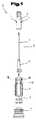
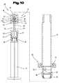
注射器ヘッド21は図1に示されているように、カニューレ3及びカニューレホルダ4を備えたニードルユニット12を有している。ニードルユニット12はガイドスリーブ5内に挿入される。注射直前にカニューレ3を封印済みの注射筒と結合するために、ニードルユニット12は、図示されていない注射筒の方向に駆動装置2によって駆動される。駆動装置2はニードルユニット12に被せ嵌められる。駆動装置2と、カニューレホルダ4と、ガイドスリーブ5とは好ましくはプラスチックから製造されている。 The
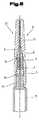
図3には、嵌め合わせ済みの注射器ヘッド21が示されている。駆動装置2は2つのガイドノブ1を有している。ガイドノブ1は、注射器ヘッド21の非操作状態において、それぞれ1つの滑子案内軌道10の入口の前に配置されている。滑子案内軌道10はガイドスリーブ5に設けられた切欠きである。滑子案内軌道10はガイドスリーブ5上でそれぞれ反対方向の勾配を有して延びている。駆動装置2が回転運動させられると(これは例えば、図1〜3に示されていない保護キャップの薄層が駆動装置2の、長手方向軸19に沿って延びるウェブ13内に係合することによって行うことができる)、ガイドノブ1のうちの一方が滑子案内軌道10のうちの一方の軌道内に案内されるのに対して、他方のガイドノブ1は妨害されることなしに、ガイドスリーブ5の一方の空間もしくは空隙18内に進入する。一方の滑子案内軌道10内に案内されているガイドノブ1は、この滑子案内軌道10の勾配に追従し、そして駆動装置2をニードルユニット12と一緒に注射筒の方向に動かす。このように、ニードルユニット12は左回転時にも右回転時にも注射筒に向かって動かされる。ニードルユニット12の周面、及びガイドスリーブ5に対応して成形された内側通路は、ニードルユニット12が駆動装置2による駆動時には回転することができず、線状に注射筒へ向かって動かされるように形成されている。図1〜3に示されているように、ニードルユニット12の完全な運動のための駆動装置2の回転は約90°である。 FIG. 3 shows the fitted
駆動装置2はさらに図2に示されているように、係止フック8を有している。係止フックはほぼガイドノブ1の高さで駆動装置2の他の周面側に配置されている。注射器ヘッド21の非操作状態において、係止フック8はガイドスリーブ5の窓9内に位置決めされている。係止フック8をこの位置から引き出すために、機械的な抵抗を克服することが必要となる。これにより、注射器ヘッド21の非操作状態では意図せぬ作動が防止される。駆動装置2が回転すると、係止フック8は、ガイドノブ1に割り当てられていない滑子案内軌道10の端部まで移動する。滑子案内軌道10はそれぞれ図3に示されているように、水平方向の滑子案内拡張部11を有している。駆動装置の回転完了後には、一方の滑子案内拡張部11内に一方のガイドノブ1が位置し、そして他方の滑子案内拡張部11内に係止フック8が位置する。駆動装置2を回し外すこと、ひいてはニードルユニット12をさらに動かすことは今やもはや不可能である。それというのも滑子案内軌道10の互いに反対方向の勾配が、ガイドノブ1及び係止フック8の運動を互いにブロックするからである。このことは注射器に対する安全な取り扱いを助成する。それというのも、カニューレと注射筒との複数回の結合及び解離が不可能だからである。 The
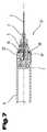
注射器ヘッド21は、図1〜3に示された第1実施態様では、その遠位端にカップリング体6を有している。カップリング体は好ましくはガイドスリーブ5の遠位端として形成されている。カップリング体6は例えば注射筒のシールエレメント7と嵌合の形で1つにまとめることができる。シールエレメント7の遠位端は注射筒と固く結合されているか、又は注射後に注射筒内に引き込み可能な構造群の一部であってよい。これにより、注射器ヘッド21は複数のタイプの注射器に被せ嵌めることができる。 The
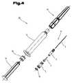
図4は、本発明による完全な状態の注射器20の第2実施態様を示している。ガイドスリーブ5の遠位端は平らに形成されており、シール板19に接続されている。1つにまとめられた状態では、シール板19は注射筒15の近位端に接触している。この注射筒内には、流体を動かすためのピストンロッド17とピストン栓16とが差し込まれている。注射筒15のヘッドは注射器ヘッド21とともに保護キャップ14によってカバーされる。 FIG. 4 shows a second embodiment of the
図5に示されているように、保護キャップ14は注射筒15に被せ嵌められ、これによりガイドスリーブ5をシール板19と、注射筒15の近位端とに押し付ける。保護キャップ14は周知の形式で保護キャップ基部22並びに保護キャップ先端23を有している。これらの保護キャップ基部22と保護キャップ先端23とは目標破断個所24を介して結合されている。保護キャップ先端23を回転させることにより、目標破断個所24は保護キャップ先端23と保護キャップ基部22との間で破断される。保護キャップ先端23の内側薄層は、駆動装置2のウェブ13内に係合し、これによりさらに駆動装置2を回転運動させる。これにより、最終的に駆動装置2とニードルユニット12とは上述のように注射筒15の方向に動かされ、シール板19が穿通される。 As shown in FIG. 5, the
これとは無関係に、駆動装置2にただ1つのガイドノブ1を設けるだけで十分であって、このガイドノブ1を選択された回転方向(時計回り方向又は反時計回り方向)に応じて、互いに反対方向に形成された両滑子案内軌道10のうちの一方に選択的に係合させ、これと相俟ってカニューレホルダ4をカニューレ3とともに注射筒15の方向に向かって移動させることも可能である。さらに、窓9と連携した状態で係止フック8を配置することもしくは設けることを全般的に省くこともできる。これにより、より簡単な形状を達成することができる。 Regardless of this, it is sufficient to provide the
図6〜12には、注射器20の更なる、そして場合によってはそれ自体独立した実施態様が示されている。ここでも先行の図1〜5と同じ部分には同じ符号もしくは構成部分符号を使用する。不要の繰り返しを避けるために先行の図1〜5における詳細な説明が参照される。 FIGS. 6 to 12 show a further, and possibly independent, embodiment of the
ここに示された注射器20、特にその注射器ヘッド21のこれらの更なる実施態様は、図1〜3において説明した注射器ヘッド21と同様に形成されている。 These further embodiments of the
注射器20は送出されるべき薬剤を収容するための注射筒15を有している。この場合注射筒の近位端には注射器ヘッド21が、そして遠位端には押し出しユニット25が配置されている。注射器ヘッド21は保護キャップ14によってカバーされ、これにより、休止位置もしくは出発位置において突出する、カニューレ3の近位側先端が、汚染並びに望まれない刺し傷を招くのを防止する。保護キャップ14の保護キャップ基部22は注射筒15の近位端に被せ嵌められ、もしくはスナップ嵌めされており、好ましくは保護キャップ基部22の半径方向のプレロードによってほぼ回動不能にこれに保持されている。互いに係合する対応保持手段によって、さらに保護キャップ基部22は軸方向で注射筒15の近位端に保持されている。さらに、注射筒15の近位端、特にその端面と、長手方向軸の方向に半径方向で突出する、保護キャップ基部22のショルダとの間に、シールリング60が配置されていると一層好ましい。これにより、注射筒15と保護キャップ14との移行領域内にも細菌密な閉鎖が達成される。 The
駆動装置2には、この図示の実施例では2つのガイドノブ1が配置されている。ガイドノブ1は、長手方向軸に対して垂直に向けられた平面内に、そして周方向に互いに所定の間隔を置いて配置されている。これらのガイドノブは、ニードルユニット12を休止位置から作動位置へ変位させるために、両滑子案内軌道10のうちの一方に係合するようになっている。これにより、カニューレ3はカニューレホルダ4と一緒に作動させられ、これと相俟って注射筒15の方向へ軸方向に移動させられ、その際にシールエレメント7はその近位端領域内でカニューレ先端によって穿通される。これにより、注射筒15の内室とカニューレ3との間にライン接続が提供される。駆動装置2は、長手方向軸を中心として保護キャップ先端23を相応に回転運動させることによって駆動される。駆動装置2のウェブ13は、保護キャップ先端23の前記内側薄層と係合している。 In the illustrated embodiment, two
図6,7並びに11をまとめて見るとより明らかなように、ガイドスリーブ5の近位端領域内には、両滑子案内軌道10を形成する領域が設けられている。互いに反対方向に向いて延びるこれらの両滑子案内軌道10は、周方向に互いにずらされて配置されていることにより、相応に作動させられると、両ガイドノブ1のうちの一方と係合する。両滑子案内軌道10のうちの一方と係合していない別のガイドノブ1に対して運動自由度を十分に提供するために、両滑子案内軌道10間の周面領域内に空隙18が形成されており、この空隙は両ガイドノブ1のうちの一方を受容するために役立つ。この実施例において、空隙18は、ガイドスリーブ5の壁厚の半径方向拡大部と、これに続く減少部とによって形成されている。両滑子案内軌道10はこれにより、ガイドスリーブ5の外壁に設けられた好ましくはスリット状の切欠きもしくは貫通部として形成されており、両ガイドノブ1のうちの一方のより良好なガイドを提供する。滑子案内軌道10の端部には、前述の好ましくは水平に形成された滑子案内拡張部11が形成されている。滑子案内拡張部11内には、両ガイドノブ1のうちの一方が相応の変位後に作動位置で配置される。 6 and 7 and 11 as a whole, a region for forming both the slider guide tracks 10 is provided in the proximal end region of the
組み付け過程をある程度容易にするために、ニードルユニット12、特にそのカニューレホルダ4が駆動装置2と、長手方向軸を中心として回転可能に、しかし軸方向ではロックされた状態でカップリングされていると有利である。このために、図11から最も明らかなように、カニューレホルダ4のシャフト28に半径方向に突出する少なくとも1つの突起26が配置されている。この突起は、駆動装置2内の好ましくは半径方向で環状に延びる切欠き27と係合することができる。好ましくは、突起26も環状に形成されていてよい。この突起は、互いにロックするために切欠き27を形成する好ましくはリング状の溝内に係合する。 In order to facilitate the assembly process to some extent, the
しかしこれとは無関係に、切欠き27をカニューレホルダ4のシャフト28に設け、そして突起26を駆動装置2に設けることも可能である。 Independently, however, it is also possible to provide a
カニューレホルダ4のシャフト28には、その遠位端領域内に付設部29が形成されている。この付設部はシャフト28から半径方向に突出している。好ましくはリング状に形成されたこのような付設部29の近位端は、ロック位置もしくは保持位置で駆動装置2の遠位端に当接することができる。 An
ガイドスリーブ5内でのカニューレ3の軸方向移動中、カニューレ3を正確に直線状に軸方向運動させるために、ニードルユニット12、特にカニューレホルダ4をガイドスリーブ5内で相応に直線状に案内することができる。このためには例えば、カニューレホルダ4の付設部29に少なくとも1つのガイド機構30が配置されていてよい。ガイド機構30は、ガイドスリーブ5の内側に設けられた詳しくは示されていないガイド軌道とガイド係合している。好ましくは、複数のガイド機構30が、ガイドスリーブ5の、これらと協働するガイド軌道とともに設けられていてもよい。さらにカニューレホルダ4は、ガイドスリーブ5内に挿入された後、休止位置もしくは出発位置において、近位側に向かって軸方向にロックされた状態でカップリングされていてもよい。これにより、組み付け過程時にも長手方向案内に加えてある程度のカップリング作用が達成され、ガイドスリーブ5からの意図されない解離が阻止される。 During the axial movement of the
既に前述したように、保護キャップ14の保護キャップ基部22は注射筒15の近位端に被せ嵌められ、その半径方向のプレロードによってほぼ回動不能に注射筒15に保持されている。また、保護キャップ14、特にその保護キャップ基部22に対するガイドスリーブ5の相対変位を阻止するために、ガイドスリーブ5の外側に、少なくとも1つの長手方向リブ31が配置もしくは形成されている。ガイドスリーブ5の一区分が保護キャップ基部22の貫通口内に収容されている。長手方向リブ31の近位端は、そのために設けられた係止機構32で、注射器ヘッド21を有する保護キャップ14の内側に支持されている。好ましくは複数の長手方向リブ31と係止機構32とが協働することによって、ガイドスリーブ5は保護キャップ14に対して、長手方向軸を中心とした回転をロックされた状態で保持されている。 As already described above, the protective
これにより、既に前述したように、長手方向軸を中心として、両方向のうちの一方(時計回り方向又は反時計回り方向)に保護キャップ先端23を回動させ、そしてこれにより保護キャップ先端23と保護キャップ基部22との間の目標破断個所24を分断することによって、ニードルユニット12が作動させられる。保護キャップ先端23と駆動装置2とを駆動接続することによって、そしてさらに続いて駆動装置2のガイドノブ1が滑子案内軌道10内で案内された状態で移動することによって、カニューレ3はカニューレホルダ4と一緒に遠位方向に注射筒15に向かって軸方向変位することになる。この際に、カニューレホルダ4はガイドスリーブ5内で直線状に案内された状態でシールエレメント7に向かって軸方向にスライドし、これを穿通する。 As a result, as described above, the
このような作動位置に達すると、特にカニューレホルダ4のニードルユニット12がガイドスリーブ5に軸方向に保持もしくはロックされる。このことは、一方ではカニューレホルダ4の付設部29の近位側が第1ロックエレメント33を形成することによって行われる。更なるロックエレメント34はガイドスリーブ5に形成もしくは配置されており、好ましくは半径方向に弾性変形可能なばねアームに配置されている。更なるロックエレメント34はニードルユニット12の作動位置において第1ロックエレメント33に背後から係合する。これにより、ニードルユニット12は近位方向に軸方向で保持される。両ロックエレメント33,34は作動位置においてロック装置35を形成する。特に付設部29のニードルユニット12は、作動位置において、ガイドスリーブ5の内部に配置された底部エレメント36に当接する。底部エレメント36には、カニューレ3の遠位端を貫通させるための貫通口が設けられている。このように一方では底部エレメント36によって、そして他方ではロックエレメント33,34が協働することによって、作動位置においてニードルユニット12の付設部29は軸方向で両側にロックされた状態で保持されている。ロックエレメント34によって、カニューレホルダ4の近位側での軸方向変位を阻止することができ、これにより、カニューレ3が注射器20から望まれない状態で解離もしくは離隔することなしに、押し出しユニット25によって薬剤を送出することができる。 When such an operating position is reached, in particular the
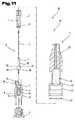
図6,8及び10をまとめて見ると、押し出しユニット25は、注射筒15の遠位端領域内に押し出しユニット25が位置していることが判る。押し出しユニット25は、ピストン栓16、ピストンロッド17、並びにピストンロッド17とピストン栓16とをカップリングもしくは結合するカップリング部材37を有している。ピストン栓16はピストンロッド17に向いた端部から出発してこのピストン栓内に延びる袋孔38を有している。袋孔は近位側で底部39によって閉じられている。ピストン栓16の外側はシール作用を有して、しかしスライド可能に注射筒15の内側に接触している。 6, 8 and 10 together, it can be seen that the
カップリング部材37は基体40を有している。この基体から出発してピストン栓16に向かって、すなわち近位方向に、突出したカップリング突出部41が延びている。カップリング突出部41のカップリング突出部端部42は袋孔38内に突入している。押し出しユニット25の非操作出発位置では、カップリング突出部端部42は好ましくは底部39から所定の間隔を置いて配置されているので、底部39は、穿通されていない膜を形成している。この膜は、ピストン栓16と協働して注射器15の内室を細菌密に閉鎖する。さらに、非操作出発位置では、ピストン栓16は軸方向で基体40から所定の間隔を置いて配置されている。カップリング突出部41にピストン栓16を位置ロックするために、カップリング突出部41には、少なくとも1つの第1係止エレメント43が配置もしくは形成されている。第1係止エレメント43は非操作出発位置では、ピストン栓16の袋孔38の領域内に配置された係止切欠き44内に係合もしくは挿入されている。これとは無関係に、係止エレメント43をピストン栓16に、そして係止切欠き44をカップリング突出部41に配置もしくは形成することも可能である。 The
第1係止エレメント43と係止切欠き44とが協働することによって、ピストン栓16はカップリング突出部41に軸方向に互いに保持もしくはロックされる。こうして、このような位置において、前組み付け済みの押し出しユニット25を、送出されるべき薬剤の充填後に注射筒15内へ挿入することができる。薬剤の充填前には、注射器ヘッド21のユニットをなおも注射筒15に組み付けなければならず、もしくは固定しなければならない。これにより、注射器ヘッド21のユニットを先ず組み立て、遠位端から出発して注射筒15内へ押し込むことができる。この際に、注射器ヘッド21のユニットは既に滅菌されていてよい。滅菌周囲条件において挿入した後、薬剤を充填することができる。続いて、やはり滅菌された押し出しユニット25を同様に挿入する。このように、薬剤を収容する内室は作動に至るまで滅菌状態である。作動によって初めて薬剤へのアクセスがカニューレ3を介して可能になる。 By the cooperation of the
カップリング突出部41のカップリング突出部端部42は、ピストンロッド17とは反対側、すなわちその近位端に、矢状にテーパした状態で形成されている。このような矢状のテーパは、シールエレメント7内に形成された更なる袋孔内に進入可能にし、そしてカップリング突出部端部42とシールエレメント7との間に、注射器ヘッド21のユニット全体を引き込み運動させるためのカップリング結合を可能にするために役立つ。このようなカップリング結合を形成するために、カップリング突出部端部42には、カップリング突出部41の断面から突出する少なくとも2つの係止アーム45が設けられている。係止アーム45はある程度の固有剛性を有しており、シールエレメント7の材料の弾性変形により、この更なる袋孔内に係止アーム45を押し込むことができる。係止アーム45のこのような構成によって、カップリング突出部端部42をシールエレメント7の袋孔内により容易に、そして大きい抵抗なしに進入させることができる。所定の距離だけ押し込まれた後、係止アーム45は、シールエレメント7の袋孔内に配置もしくは形成されたショルダの背後に配置されている。係止アーム45の強度及び選択された材料に応じて、係止アームはある程度の範囲内で弾性を有することができる。係止アーム45の断面が小さいため、係止アームはショルダと、シールエレメント7の袋孔内で所望のカップリング結合を形成する。これにより、係止アーム45は戻し運動時に弾性変形可能なシールエレメント7内にある程度固着もしくは係止される。まさにシールエレメント7の表面がシリコン処理されている場合には、係止アーム45のこのような構成は、大抵は環状に形成された係止円錐体の代わりとして有利である。このようにすると、ショルダと、遠位方向に前置された貫通口とをより小さな断面で形成することができる。この断面はカップリング突出部41の断面を収容するためにだけ役立つ。次いで、カップリング突出部41の周面全体に対して僅かな断面幅を有してここから突出する係止アーム45は、シールエレメント7の弾性変形に起因して、そして場合によってはカップリング突出部41の空隙と相俟って生じる係止アーム45の半径方向弾性変形に起因して、袋孔内に進入する。 The coupling
カップリング部材37とピストンロッド17とをカップリングするために、カップリング部材37の基体40には、ピストンロッド17に向いた側で、弾性変形可能なカップリングアーム46が設けられていてよい。カップリングアーム46は、ピストンロッド17に形成されたカップリングエレメント47に解離可能にカップリングすることができる。カップリングアーム46は好ましくは半径方向にばね弾性的に形成されており、ピストンロッド17に向いた側でカップリングエレメント47に背後から係合している。カップリングエレメント47とのカップリング位置におけるカップリングアーム46の寸法は、注射筒15の内側寸法にほぼ相当する外側寸法を有するように選択されている。これにより、カップリングエレメント46を半径方向に拡大させ得るように、ひいては分離過程を実施するために断面がある程度拡張されるまでは、ピストンロッド17を分離することはできない。注射筒15は大抵の場合ガラスから形成されているので、その内壁が全長にわたって、ほぼ同じ断面もしくは断面寸法を有していると有利である。 In order to couple the
図8からよりよく判るように、ここでは押し出しユニット25はその作動位置に位置しており、この作動位置では、カップリング突出部端部42はピストン栓16の底部39を穿通しており、その遠位端は基体40の近位端に当接もしくは支持されている。このような押し出し位置において、予めピストン栓16の係止切欠き44内に配置されていた第1係止エレメント43は相対変位後に、袋孔38の底部39の内側の、カップリング突出部41によって貫通された領域に当接する。底部39のこのような支持作用によって、ピストン栓の近位端面の、カップリング突出部41の接触領域もしくは貫通領域に対する付加的なシール作用がもたらされる。これは底部39の壁厚が比較的薄く、ひいては、送出過程中に発生する内圧がこの領域内で非シール性を招くことがないからである。 As can be seen better from FIG. 8, here the
図9には、注射筒15内部のニードルユニット12の引き込み位置、ひいては保護位置が示されている。この場合、ピストンロッド17は既にカップリング部材37から分離されている。ピストン栓16のこのような引き込み運動をよりよく実施できるようにするために、付加的にカップリング突出部41の、基体40と第1係止エレメント43との間に、少なくとも1つの更なる係止エレメント48が配置もしくは形成されていてよい。この係止エレメントは、押し出しユニット25の戻し運動時にニードルユニット12と一緒に、ピストン栓16の袋孔38内に形成されたショルダ49に当接する。ショルダ49を形成するために、袋孔は、異なる断面50,51を有する区分を有することができる。ここで示された実施例の場合、断面51は、底部39に向いた区分の領域における断面50よりも小さな断面寸法を有している。 FIG. 9 shows the retracted position of the
図9及び10をまとめて見るとより明らかなように、既に前述したように、注射筒15はその狭められた近位端から遠位端へ向かって、ほぼ同じ断面寸法を有している。注射筒15の遠位端には、さらに単純化されてハンドリングエレメント52が示されている。ハンドリングエレメント52は押し出しユニット25の構成部分であることが好ましい。このようなハンドリングエレメント52は半径方向で1つにまとめることができる2つの半割体から形成されることが好ましい。これらの半割体は、注射筒15の突出部53を介して注射筒に軸方向に固定された状態で保持されている。ハンドリングエレメント52を形成するために両半割体を相互に結合する際には、それぞれ周知のスナップエレメント及び/又は係止エレメントが役立つことができる。 As will be more apparent when viewing FIGS. 9 and 10 together, as already described above, the
ピストンロッド17のカップリングエレメント47とカップリング部材37のカップリングアーム46との前述の分離過程を実施できるようにするために、ハンドリングエレメント52の貫通通路55の、遠位区分における内法幅54は、カップリングアーム46の非変形位置における外側断面寸法よりも大きい。これにより、分離過程を実施できるようにするために、カップリングアーム46を半径方向に拡張することができる。 In order to be able to carry out the aforementioned separation process of the
注射筒15に対してカップリングエレメント47を軸方向に位置固定し、ひいては注射器20の新たな再使用を回避するために、特に基体40のカップリング部材37とハンドリングエレメント52との間に保持装置56が、協働する保持エレメント57,58とともに形成されている。ここに示したこのような実施例において、第1保持エレメント57はカップリング部材37の基部40に、例えば環状の溝状凹部の形で形成されている。この凹部内に、少なくともこの更なる保持エレメント58は固定位置において係止係合する。ハンドリングエレメント52の領域内のこの更なる保持エレメント58は半径方向にばね弾性的にもしくは弾性変形可能に形成されていてよい。保持エレメント58は、カップリング部材37の十分な戻し運動後、そのために設けられた第1保持エレメント57内にロックされた状態で係止される。相互に選択された保持エレメント57,58の構成及び種類に応じて、残された押し出しユニット25並びにニードルユニット12の少なくとも一方の方向(近位及び/又は遠位)への軸方向変位を阻止することができる。しかしまたこれにより、残された押し出しユニット25をニードルユニット12と一緒にさらに引き出すことを阻止できることも好ましい。 In order to fix the
ピストンロッド17のカップリングエレメント47を、カップリング部材37、特にその基体40のカップリングアーム46内に新たに挿入するのを阻止するために、ハンドリングエレメント52には、その遠位端の領域内に少なくとも1つの誘導エレメント59が配置されている。誘導エレメントは貫通通路55の断面内に突入している。誘導エレメント59は例えば長手方向軸に向かってアーチ状に湾曲するように形成されていてよい。しかしながら、ピストンロッド17を注射器20内へ新たに再挿入するのを阻止するためには複数の誘導エレメント59が設けられるのが好ましい。 In order to prevent the
もちろん、前記実施例は本発明の思想の範囲内で種々様々に、例えばガイドノブ1の相互の配置関係及び/又は係止フック8に対する配置関係に関して、滑子案内軌道10の材料並びに勾配角度に関して変更を加えることができる。 Of course, the embodiments described above vary in various ways within the scope of the idea of the invention, for example with respect to the mutual arrangement of the guide knobs 1 and / or the arrangement with respect to the locking hooks 8 and with respect to the material of the
前記注射器20は、既に薬剤が充填されていて送出の準備ができているタイプの注射器である。これは充填済み注射器(Fertigspritze)、特にガラス製充填済み注射器と呼ばれる。注射筒15の材料はガラスから選択されている。薬剤を収容する注射器内室の近位端は、作動させるまでは穿通されないシールエレメント7によって、そして遠位端はやはりまだ穿通されていないピストン栓16によって、注射筒7の内壁に対して細菌密にシールされる。保護キャップ先端23を回動させることによって注射器ヘッド21を作動させて初めて、カニューレ3の遠位端はシールエレメント7の底部を穿通し、これにより注射筒15の内室、ひいては薬剤とのライン接続を形成する。次いで貯えられた薬剤を放出することができる。 The
図13〜16には、注射器20の更なる、そして場合によってはそれ自体独立した実施態様が示されている。ここでも先の図1〜12と同じ部分には同じ符号もしくは構成部分符号を使用する。不要の繰り返しを避けるために先の図1〜12における詳細な説明が参照される。 FIGS. 13-16 show a further and possibly independent embodiment of the
ここに示されたこのような注射器20は、既に特に図6〜12において説明したものと同様に形成されている。このような実施変更形の場合、注射筒15の内部に貯えられた薬剤を放出した後、利用者の更なる支援なしに使用済みニードルの保護位置に達することが、この種の注射器20の利用者もしくは使用者に可能になる。利用者の支援なしにこれを行うことを受動的ニードル保護システムと呼ぶことができる。これに対して注射筒から薬剤を送出した後、利用者によって独自のステップを設定する場合に、ニードル保護位置に達することは、能動的ニードル保護システムと呼ばれる。このような独自のステップは、メカニズムの意識的且つ意図的な作動であってよい。 Such a
このように、ここに示された注射器20は、詳しくは示されていない薬剤を収容するための注射筒15と、ピストンロッド17及びこれにカップリングされたカップリング部材37とを有している。カップリング部材37には、ピストン栓16が配置されていてもよい。ニードルユニット12は、これが非利用位置では保護キャップ14によってカバーされ、カニューレ3の遠位端が注射筒15の内室とはまだ流れ接続されないように形成されている。流れ接続を形成するためには、カニューレ3の遠位端がシールエレメント7を穿通しなければならない。これにより所望の流れ接続を形成することができる。保護キャップ14は保護キャップ基部22と、これに配布状態では結合されている保護キャップ先端23とを有することができる。保護キャップ先端23によって、既に前述したように、カニューレ3を作動させることができる。 Thus, the
カップリング部材37はここでも、ピストン栓16とピストンロッド17とを互いにカップリングもしくは結合するのに役立つ。このためには、カップリング部分37の基体40に、ピストンロッド17に向いた側で、固有のカップリング装置61が設けられている。カップリング装置61は、互いに協働するカップリングエレメント62,63を有することができる。ここに示された第1カップリングエレメント62は例えば円錐台状の付設部として形成されていてよい。この付設部は基体40に向いた側にアンダカットを備えていて軸方向に延びている。ピストンロッド17の近位端には、更なるカップリングエレメント63が配置されている。このカップリングエレメント63はカップリング位置において第1カップリングエレメント62とカップリング係合している。 The
さらに、注射筒15の遠位端には、前述のハンドリングエレメント52が配置されている。ハンドリングエレメント52の中心はピストンロッド17によって貫通されている。ハンドリングエレメント52は好ましくは注射筒15の突出部53に保持されている。 Furthermore, the
ハンドリングエレメント52とピストンロッド17との間には、ここでは戻し装置64が設けられている。「間」とはここでは、戻し装置64が一方ではハンドリングエレメント52に支持されていて、他方ではその解放後に、ピストンロッド17、カップリング部材37、ピストン栓16、並びにピストン栓に必要に応じてカップリング可能なニードルユニット12が、注射筒15に対して遠位方向に、近位位置から遠位位置へ向かって変位させられることを意味する。このような戻し位置は図16に示されている。 Here, a
例えば戻し装置64は少なくとも1つのばねエレメント65を有していてよい。ばねエレメントはプレロード位置において、軸方向に作用する移動力を形成する。この移動力は戻し装置64の係止解除もしくは解離後に作用する。ばねエレメント65は圧縮ばね、特にらせんばねであってよい。ここでは、ばねエレメント65の近位端はハンドリングエレメント52に直接に支持されている。さらにここでは半径方向で見て、ばねエレメント65とピストンロッド17との間に、固有の、特に管状に形成されたスライド体66が配置されている。スライド体66の外周もしくはスライド体の周りに、ばねエレメント65が配置されている。スライド体66はばねエレメント65をその遠位端で支持するために役立つ。さらに、スライド体66は、ばねエレメント65のプレロード位置においてハンドリングエレメント52の遠位端領域内に、拘束装置67によって必要に応じて解離可能に保持もしくは支持されている。 For example, the
拘束装置67は、協働する拘束エレメント68,69を有することができる。ここでは例えば拘束エレメント68はノーズ状付設部としてスライド体66に配置されている。付設部はスライド体66から半径方向に突出している。拘束エレメント68は解放されたばねアームに配置されていてよい。これにより拘束エレメント68は半径方向で長手方向軸に向かって旋回させられる。これと協働する更なる拘束エレメント69は、例えばハンドリングエレメント52の切欠き、スリット、又は貫通口であってよい。この更なる拘束エレメント69には、第1拘束エレメント68がばねエレメント65のばね力を散逸させながら支持されている。 The restraining
これにより、プレロードをかけられたばね蓄圧器を提供することができる。蓄圧器は操作もしくはリリース時には自動的な戻し、ひいては受動的なニードル引き込みを生じさせる。Thereby, a preloaded spring accumulator can be provided. The accumulator will automatically return when operated or released, thus creating a passive needle retraction.
注射器20は、既に前述したように予め薬剤を貯えられそして配布される。送出過程のための操作は、図1〜12において既に前述したように行うことができる。しかしながら、図1〜12に示した実施態様の場合、保護位置に到達するためには、利用者は能動的にニードルを戻すことを介してニードルを注射器15内部に自分で引き戻すことが必要である。 The
図15からよりよく判るように、この場合には既に、十分な量の薬剤が注射筒15から送出されている。カップリング部材37のカップリング突出部端部42はシールエレメント7、並びにシールエレメントにカップリングされたニードルユニット12とカップリング係合されている。 As can be seen from FIG. 15, in this case, a sufficient amount of medicine has already been delivered from the
拘束装置67はここでは、協働する調節エレメント70,71によってリリースされる。これらの調節エレメント70,71は、ピストンロッド17が注射筒15、もしくは注射筒に配置されたハンドリングエレメント52に対して所定の距離だけ移動したあと、拘束装置67の協働する拘束エレメント68,69は、プレロードをかけられた戻し装置64のばねエレメント65が戻し力を生じさせるまで係合解離される。これにより、少なくともニードルユニット12のカニューレ3の近位端が、注射筒15内部もしくはこれに保持された保護キャップ基部22内部に位置するまで、ピストンロッド17をこれにカップリングされた構成部分もしくはエレメントと一緒に戻すことができる。 The restraining
調節エレメント70,71は例えば注射器20の長手方向軸に対して円錐状もしくはアングル状に延びるように配向された調節面72,73を有することができる。調節面72,73の同一の円錐状の配向もしくはアングル状の傾斜によって、これらの調節面は図15から判るように互いに接触する。これにより、前述の拘束エレメント68,69は相互の係止係合状態を解離される。傾斜した調節面72,73は相互に接触すると、ここではノーズ状に形成された拘束エレメント68は半径方向で長手方向軸に向かって変位させられ、ひいては更なる拘束エレメント69との係合状態を解離される。これら両拘束エレメント68,69が係合解離されると、戻し装置64のばねエレメント65は、スライド体66がピストンロッド70にその遠位端で接触した状態で、ピストンロッド17を、これにカップリングされた構成部分と一緒に戻すことができる。ニードルユニット12のこのような保護位置は図16から判る。この場合、例えば第1調節エレメント70がスライド体66に、そして更なる調節エレメント71がピストンロッド17に配置されもしくは設けられている。このように、拘束エレメント68,69は送出過程中に自動的且つ自己作動的にリリースされ、更なる別個のリリース過程を実施する必要はない。 The
注射器20の新たな操作を回避するために、カップリング部材37、特にその基体40と、ハンドリングエレメント52との間に、前述の保持装置56がその保持エレメント57,58と一緒に設けられていてよい。保持エレメント57,58は例えば、協働する係止フックもしくは係止ノーズによって形成されていてよい。これらの係止フックもしくは係止ノーズは、その係合位置において新たな操作、ひいては注射筒15に対するニードルユニット12の相対変位が確実に回避されるように互いに係合している。 In order to avoid a new operation of the
注射筒15内部に位置するカニューレ3のカニューレ先端のこのような保護位置において、次いでためらうことなしに、注射器20全体を廃棄処分することができる。 In such a protected position of the cannula tip of the
従って、戻し装置64のこのような構成によって、利用者はカニューレ3を保護位置に到達させるために、付加的なリリースステップを設定せずにすみ、受動的ニードル引き込み中に戻し装置64によってこれを自動的に行うことができる。 Thus, with this configuration of the
しかし前述の戻し装置64は、これとは独立して例えば国際公開第2007/112470号パンフレットに記載されているような注射器と組み合わせることもできる。このような注射器はここに示した実施態様とは、カニューレが既に初めから注射筒の内室と、ひいては薬剤と流体接続している点においてのみ異なっている。ここで図1〜16に記載されたこのような実施態様において、カニューレ3の遠位端は、薬剤を意図的に送出する直前になって初めて注射筒15の内室と、ひいては内室内に貯えられた薬剤と流体接続される。 However, the
さらに、個々の構成部分の非利用位置は、休止位置もしくは元状態と呼ばれ、そして注射筒15の内室とライン接続が形成されているニードルユニット12の位置は、作動位置と呼ばれる。押し出しユニット25の同じ動作状態もしくは位置もこのような記述で表すことができる。ニードルユニット12が注射筒15内へ戻されている場合には、廃棄処理位置もしくは保護位置と呼ぶことができる。 Furthermore, the non-use position of the individual components is called the rest position or the original state, and the position of the
規則上最後に述べておくが、注射器20の構造をよりよく理解するために、注射器ヘッド21もしくはその押し出しユニット25、その構成部分は部分的に一定の尺度でなく、且つ/又は拡大し、且つ/又は縮小して示した。 As a rule last, in order to better understand the structure of the
独立した本発明の解決手段の根底を成す課題は、明細書から明らかである。 The problem underlying the independent solution of the present invention is clear from the description.
当該記述における値範囲に関する全ての数値は、これらの任意の、及び全ての部分範囲を一緒に含むように理解されるべきである。例えば、数値1〜10は、下限値1及び上限値10から出発する全ての部分範囲が一緒に含まれるように、すなわち、全ての部分領域が下限値1以上で始まり、そして上限値10以下で終わる、例えば1〜1.7、又は3.2〜8.1、又は5.5〜10であるように理解されるべきである。 All numerical values relating to value ranges in the description should be understood to include any and all of these subranges together. For example, the
これらの実施態様は、注射器20、特にその注射器ヘッド21並びにその押し出しユニット25の可能な実施変更形を示す。ここでは、本発明は具体的に示された実施変更形に限定されることはなく、むしろ個々の実施変更形の種々の組み合わせが互いに可能であり、そしてこのような変更は、この技術分野で活動する当業者の能力範囲内で、本発明による技術的行為のための教示内容に基づいて可能であることに留意されたい。つまり、上記実施変更形の個々の詳細を組み合わせることにより可能になる、考えられ得る全体的な実施変更形も、権利範囲に含まれる。さらに、図示され説明された種々異なる実施態様の個々の特徴又は特徴の組み合わせも、それ自体独立した、本発明の、又は本発明による解決手段であり得る。 These embodiments show possible implementation variants of the
とりわけ、図1,2,3;4;5;6〜12;13〜16に示された実施態様における個々のものが、独立した本発明の解決手段の対象を形成することができる。これに関する本発明による課題及び手段は、これらの図面の詳細な説明から明らかである。 In particular, the individual ones in the embodiments shown in FIGS. 1, 2, 3; 4; 5; 6-12; 13-16 can form the subject of an independent solution of the invention. The subject matter and means of the present invention in this regard will become apparent from the detailed description of these drawings.
1 ガイドノブ
2 駆動装置
3 カニューレ
4 カニューレホルダ
5 ガイドスリーブ
6 カップリング体
7 シールエレメント
8 係止フック
9 窓
10 滑子案内軌道
11 滑子案内拡張部
12 ニードルユニット
13 ウェブ
14 保護キャップ
15 注射筒
16 ピストン栓
17 ピストンロッド
18 空隙
19 シール板
20 注射器
21 注射器ヘッド
22 保護キャップ基部
23 保護キャップ先端
24 目標破断個所
25 押し出しユニット
26 突起
27 切欠き
28 シャフト
29 付設部
30 ガイド機構
31 長手方向リブ
32 係止機構
33 ロックエレメント
34 ロックエレメント
35 ロック装置
36 底部エレメント
37 カップリング部材
38 袋孔
39 底部
40 基体
41 カップリング突出部
42 カップリング突出部端部
43 係止エレメント
44 係止切欠き
45 係止アーム
46 カップリングアーム
47 カップリングエレメント
48 係止エレメント
49 ショルダ
50 断面
51 断面
52 ハンドリングエレメント
53 突出部
54 内法幅
55 貫通通路
56 保持装置
57 保持エレメント
58 保持エレメント
59 誘導エレメント
60 シールリング
61 カップリング装置
62 カップリングエレメント
63 カップリングエレメント
64 戻し装置
65 ばねエレメント
66 スライド体
67 拘束装置
68 拘束エレメント
69 拘束エレメント
70 調節エレメント
71 調節エレメント
72 調節面
73 調節面DESCRIPTION OF
本発明は、送出されるべき薬剤を収容するための注射筒と、該注射筒の遠位端に配置された押し出しユニットと、該注射筒の近位端に配置された注射器ヘッドとを有する注射器であって、該注射器ヘッドは、ガイドスリーブ内に配置されて該ガイドスリーブ内でスライド可能な、カニューレ及びカニューレホルダを備えたニードルユニットと、駆動装置とを有しており、該駆動装置によって、該ニードルユニットが休止位置から作動位置へ向かって該注射筒に対して軸方向に運動可能であり、該注射器ヘッドはさらに、該ガイドスリーブの遠位端に配置されたシールエレメントを有しており、該シールエレメントは、該ニードルユニットの休止位置では該カニューレによって穿通されておらず、そして該ニードルユニットの作動位置では該カニューレによって穿通されている形式のものに関する。The present invention relates to a syringe having a syringe barrel for containing a medicine to be delivered, an extrusion unit disposed at the distal end of the syringe barrel, and a syringe head disposed at the proximal end of the syringe barrel. The syringe head includes a needle unit with a cannula and a cannula holder disposed within the guide sleeve and slidable within the guide sleeve, and a drive device, The needle unit is movable axially relative to the syringe barrel from a rest position to an actuated position, the syringe head further comprising a sealing element disposed at the distal end of the guide sleeve; The sealing element is not pierced by the cannula in the rest position of the needle unit and the cartridge is in the actuated position of the needle unit. About of the type which is penetrated by Yure.
本明細書において、「近位」及び「遠位」という方向は、患者側から見て定義される。従って、近位側は以下に記載する構成部分において、常に患者に向いており、そして遠位側は常に患者とは反対側に向いている。注射器、特に使い捨て注射器は、薬剤を投与するためのよく知られた手段である。しばしば患者自身によって使用される使い捨て注射器の場合、カニューレを使用直前に初めて回転運動によって注射筒に結合する。 In this specification, the directions “proximal” and “distal” are defined as viewed from the patient side. Accordingly, the proximal side is always facing the patient and the distal side is always facing away from the patient in the components described below. Syringes, especially disposable syringes, are well known means for administering medication. In the case of disposable syringes, often used by the patient himself, the cannula is first coupled to the syringe barrel by a rotational motion just prior to use.
オーストリア国特許第404 430号明細書に基づいて公知の注射器ヘッドの場合、カニューレは選択的に左回転又は右回転によって、注射筒の出口に設けられたシール板を穿刺するので、どの方向で回転しなければならないか、或いは一方の回転方向が注射器の安全な使用を阻害するかどうかという指示を患者は予め必要とはしない。このために、オーストリア国特許第404 430号明細書の教示内容によれば、カニューレ支持体がカニューレ支持体ガイド内に挿入されている。カニューレ支持体は、近位端に向かって分岐するY字形ガイド溝を有している。このガイド溝内には、ガイド支持体ガイド内のガイドピンが係合する。カニューレ支持体が回転すると、ガイドピンは溝の左側又は右側の脚部を通走し、これによりカニューレ支持体は右回転又は左回転でシール板方向に移動する。このような解決手段の欠点は、ガイドピンがカニューレ支持体ガイドの内側に配置されていなければならず、このことは製造上大きな手間がかかり、高い廃棄物発生率を伴うことにある。更なる欠点は、カニューレ支持体を終端位置から引き出すことがさらに可能であり、すなわち使用者がカニューレと、穿刺されたシール板との結合を意図的に又は意図せずに解離し得ることにある。さらに、カニューレの斜め面取りされた遠位端がシール板内に回し入れられ、そして穿孔が形成されると、シール板材料から成る摩耗粒子が発生して、これらが次いで流動状薬剤中に達し得ることも不都合である。さらに、利用したカニューレは使用後に、保護キャップの一部を改めて被せ嵌めることによってしか再び保護することができず、このことは刺し傷の発生に結び付くおそれがある。 In the case of a syringe head known from Austrian Patent No. 404 430, the cannula selectively punctures a sealing plate provided at the outlet of the syringe barrel by left or right rotation, so that it rotates in any direction. The patient does not need prior instructions as to whether or not one direction of rotation will interfere with the safe use of the syringe. For this purpose, according to the teaching of Austrian patent 404 430, a cannula support is inserted into the cannula support guide. The cannula support has a Y-shaped guide groove that branches towards the proximal end. A guide pin in the guide support guide engages in the guide groove. As the cannula support rotates, the guide pin runs through the left or right leg of the groove, thereby moving the cannula support toward the seal plate with a right or left turn. The disadvantage of such a solution is that the guide pins have to be arranged inside the cannula support guide, which is very laborious to manufacture and involves a high waste generation rate. A further disadvantage is that it is further possible to withdraw the cannula support from the end position, i.e. the user can intentionally or unintentionally disengage the connection between the cannula and the punctured seal plate. . In addition, when the beveled distal end of the cannula is turned into the seal plate and a perforation is formed, wear particles of seal plate material are generated that can then reach into the fluid medicament. That is also inconvenient. Furthermore, the used cannula can only be protected again after use by re-inserting a part of the protective cap, which can lead to the occurrence of punctures.
米国特許第5 250 037号明細書もしくは独国特許第693 19 702号明細書に基づいて公知の、冒頭で述べた形式の注射器ヘッドの場合、駆動装置が注射前にニードルユニットと注射筒とを結合する。この場合の欠点は、駆動装置が同時に注射器の保護キャップでもあり、操作後には注射器から取り外されることである。その結果、ニードルユニットは注射過程中、緩んだロックされていない状態でのみ注射筒と結合され続ける。ここでも、利用したカニューレは使用後に、保護キャップを改めて被せ嵌めることによってしか再び保護することができず、このことは刺し傷の発生に結び付くおそれがある。 In the case of a syringe head of the type mentioned at the outset, known from US Pat. No. 5,250,037 or DE 693 19 702, the drive unit is connected to the needle unit and the syringe barrel before injection. Join. The disadvantage in this case is that the drive device is also the protective cap of the syringe and is removed from the syringe after operation. As a result, the needle unit continues to be coupled with the syringe barrel only during the injection process in a loose and unlocked state. Again, the used cannula can only be protected again after use by re-inserting a protective cap, which can lead to the occurrence of a stab.
別の注射器が国際公開第2009/097634号パンフレットに基づいて公知となっている。このような注射器は、出発状態において保護キャップによってカバーされている注射器ヘッドを有している。注射器ヘッドは、カニューレホルダ内に保持されたカニューレ、カニューレホルダをカニューレと一緒に収容するガイドスリーブ、並びにカニューレをカニューレホルダと一緒に調節するための駆動部材を有している。注射筒に向いた端部には、ガイドスリーブにシール挿入体がスナップ嵌めされている。回転運動を保護キャップ先端から出発して駆動部材へ、さらに続いてカニューレホルダへ伝送するために、駆動部材は外側に滑子案内軌道を備えている。滑子案内軌道は、ガイドスリーブの内側に設けられたガイドピンと協働する。この場合の欠点も、ガイドピンがカニューレ支持体ガイドの内側に配置されており、このことは製造上大きな手間がかかり、高い廃棄物発生率につながることにある。しかし同時にまた、カニューレがシール挿入体の底部を貫通する、カニューレ及びそのカニューレホルダの作動位置における最終位置が一義的に与えられていない。さらに、ピストン栓に対するカップリング部材の意図せぬ変位が生じるおそれがある。これによりシール性、及びとりわけ滅菌性がもはや保証されない。米国特許第6,613,016号明細書に基づき、送出されるべき薬剤を収容するための注射筒を備えた注射器が公知である。この公知の注射器の場合、注射筒の遠位端には押し出しユニットが、そして近位端には注射器ヘッドが配置されている。注射器ヘッドは、注射筒内にスライド可能に支承された保持エレメントを、これに挿入可能なニードル装置のために有している。ニードル装置は常に注射筒の内室と流体接続している。押し出しユニットは、ロッド状エレメントが固く結合されたピストンロッドを有している。ロッド状エレメントは注射筒の内室に向いた側で、矢尻状もしくは円錐状に形成された端部を有している。ロッド状に形成されたこのようなピストンロッド体には、管状のアダプタがスライド可能に支承されている。アダプタは出発位置において、ロック装置もしくは係止装置を介して、ロッド状のピストンロッド体に対してこれにロックされた状態で保持されている。注射筒に向いたその端部には、弾性変形可能なピストン栓が保持もしくは配置されている。送出されるべき薬剤を完全に噴出させた後、ロック装置は管状のアダプタとロッド状のピストンロッド体との間で係合解離し、ピストンロッド体の矢尻状端部はシール栓を穿通し、さらに続いて注射器ヘッドの保持エレメント内に侵入する。これにより、注射器ヘッド全体を注射筒の内室内に引き込むことができる。Another syringe is known on the basis of WO 2009/097634. Such a syringe has a syringe head which is covered by a protective cap in the starting state. The syringe head has a cannula held within the cannula holder, a guide sleeve that houses the cannula holder with the cannula, and a drive member for adjusting the cannula with the cannula holder. A seal insert is snapped onto the guide sleeve at the end facing the syringe barrel. In order to transmit the rotational movement from the tip of the protective cap to the drive member and subsequently to the cannula holder, the drive member is provided with a slider guide track on the outside. The slider guide track cooperates with a guide pin provided inside the guide sleeve. The disadvantages here are that the guide pins are arranged inside the cannula support guide, which is very labor intensive and leads to a high waste generation rate. At the same time, however, the final position in the working position of the cannula and its cannula holder is not uniquely given, where the cannula penetrates the bottom of the seal insert. Furthermore, there is a possibility that unintentional displacement of the coupling member with respect to the piston plug may occur. As a result, sealing properties and in particular sterility are no longer guaranteed.According to US Pat. No. 6,613,016, a syringe with a syringe barrel for containing a medicine to be delivered is known. In this known syringe, an extrusion unit is arranged at the distal end of the syringe barrel and a syringe head is arranged at the proximal end. The syringe head has a holding element slidably mounted in the syringe barrel for a needle device which can be inserted therein. The needle device is always in fluid connection with the inner chamber of the syringe barrel. The extrusion unit has a piston rod to which rod-like elements are firmly coupled. The rod-shaped element has an end formed in an arrowhead shape or a conical shape on the side facing the inner chamber of the syringe barrel. A tubular adapter is slidably supported on such a piston rod body formed in a rod shape. In the starting position, the adapter is held in a locked state with respect to the rod-shaped piston rod body via a locking device or a locking device. At its end facing the syringe barrel, an elastically deformable piston plug is held or arranged. After completely ejecting the medicine to be delivered, the locking device disengages between the tubular adapter and the rod-shaped piston rod body, the sagittal end of the piston rod body penetrates the seal plug, Furthermore, it penetrates into the holding element of the syringe head. Thereby, the whole syringe head can be drawn into the inner chamber of the syringe barrel.
本発明の課題は、このような欠点を回避し、そして特にカニューレと注射筒とを結合した後にカニューレの更なる運動を阻止する、冒頭で述べた形式の注射器ヘッド並びに押し出しユニットを有する注射器を提供することである。本発明の更なる目的は、摩耗粒子が発生しないようにカニューレと注射筒とを結合することである。さらに、ピストン栓と押し出しユニットのカップリング部材とのカップリング結合を改善することも望まれる。The object of the present inventionis to providea syringe having a syringe head and an extrusion unit of the type mentioned at the outset, which avoids such drawbacks and prevents further movement of the cannula, in particular after coupling the cannula and the syringe barrel. It is to be. A further object of the present invention is to connect the cannula and syringe so that no wear particles are generated. It is also desirable to improve the coupling coupling between the piston plug and the coupling member of the extrusion unit.
本発明による注射器ヘッドは、該駆動装置が少なくとも1つのガイドノブを有しており、該ガイドノブは、該ガイドスリーブ内に設けられた2つの滑子案内軌道のうちの一方と選択的に係合するようになっており、該滑子案内軌道が互いに反対方向の勾配を有していることによって前記目的を達成する。 In the syringe head according to the present invention, the driving device has at least one guide knob, and the guide knob selectively engages one of two slider guide tracks provided in the guide sleeve. The above-mentioned object is achieved by the fact that the slider guide tracks have gradients in opposite directions.
この場合の利点は、ガイドノブを成形技術的により簡単に形成することができ、そしてとりわけ注射器全体の機能の確実性を高め得ることである。さらに、滑子案内軌道の構成もより簡単になり、とりわけ使用に際してより確実になる。これにより、コンパクトであり、そしてとりわけ確実且つ簡単に取り扱うことができる注射器が提供される。この注射器は、医学専門家以外の者によって使用することもでき、高い動作確実性を有する。The advantage in this case is that the guide knob can be formed more easily in terms of molding technology and in particular can increase the certainty of the function of the whole syringe. Furthermore, the construction of the slider guide track is simpler and in particular more reliable in use.This provides a syringe that is compact and can be handled particularly reliably and easily. The syringe can also be used by persons other than medical professionals and has high operational reliability.
更なる構成では、該駆動装置が2つのガイドノブを有しており、該ガイドノブは、長手方向軸に対して垂直に向けられた平面内に、そして周方向に互いに所定の間隔を置いて配置されていて、また、該ニードルユニットを休止位置から作動位置へ変位させるために、該両ガイドノブのうちの一方だけが該両滑子案内軌道のうちの一方に係合するようになっている。これにより、動作確実性はさらに高められ、より良好な操作可能性がもたらされる。 In a further configuration, the drive device has two guide knobs which are arranged in a plane oriented perpendicular to the longitudinal axis and spaced apart from one another in the circumferential direction. And only one of the two guide knobs is adapted to engage one of the two slider guide tracks in order to displace the needle unit from the rest position to the operating position. This further increases operational certainty and provides better maneuverability.
更なる好ましい実施態様の特徴は、ガイドスリーブ内には、周方向で該両滑子案内軌道の間に空隙が形成されていて、該空隙は、ニードルユニットの移動中に該滑子案内軌道のいずれとも係合しないガイドノブを受容するのに役立つことである。これにより両方のガイドノブがあるにもかかわらず、一方では、両ノブのうちの一方のノブを正確にガイドすることができ、他方では、回転運動中の引っかかりを阻止することができる。 A further preferred embodiment is characterized in that a gap is formed in the guide sleeve between the two guide guide tracks in the circumferential direction, and the gap is defined by the guide guide track during movement of the needle unit. It is helpful to receive a guide knob that does not engage either. In this way, despite the presence of both guide knobs, on the one hand, one of the two knobs can be accurately guided and on the other hand it is possible to prevent catching during rotational movement.
別の実施態様の特徴は、該ニードルユニット、特にそのカニューレホルダと、該ガイドスリーブとが作動位置で、ロック装置の協働するロックエレメントによって軸方向に互いに位置決めされた状態で保持されていることである。これにより、薬剤送出前、送出時、及び送出後に、カニューレの保証された位置が常に達成され、望ましくない軸方向変位が回避される。 Another embodiment is characterized in that the needle unit, in particular its cannula holder, and the guide sleeve are held in an axial position relative to each other in the operating position by cooperating locking elements of the locking device. It is. This ensures that a guaranteed position of the cannula is always achieved before, during and after delivery of the drug, and undesirable axial displacement is avoided.
別の構成において、該ニードルユニット、特にそのカニューレホルダが該駆動装置と、長手方向軸を中心として回転可能に、しかし軸方向ではロックされた状態でカップリングされている。これにより、カニューレをカニューレホルダと一緒に駆動装置内に前組み付けすることができ、この場合、必要な回転運動自由度が制限されることはない。 In another configuration, the needle unit, in particular its cannula holder, is coupled with the drive device so as to be rotatable about a longitudinal axis but locked in the axial direction. This allows the cannula to be preassembled together with the cannula holder in the drive, in which case the required rotational freedom is not limited.
更なる好ましい実施態様の特徴は、該ニードルユニット、特にそのカニューレホルダが該ガイドスリーブ内で、軸方向に直線状に案内された状態で支承されていることである。これにより、シールエレメントの領域内での純然たる穿通運動が達成され、シールエレメントの粒子の放出が回避される。これにより、純度の面で見てさらに確実な薬剤送出が達成される。 A further preferred embodiment is characterized in that the needle unit, in particular its cannula holder, is supported in the guide sleeve in a linearly guided state in the axial direction. This achieves a pure penetration movement in the region of the sealing element and avoids the release of particles of the sealing element. This achieves more reliable drug delivery in terms of purity.
別の実施態様の特徴は、それぞれの滑子案内軌道の端部に、滑子案内拡張部が設けられており、該滑子案内拡張部内には、該ガイドノブが係止可能であることである。付加的な係止フックが存在する場合、係止フックもまた滑子案内拡張部内に係止可能に形成されていてよい。 A feature of another embodiment is that a slide guide extension is provided at the end of each slider guide track, in which the guide knob can be locked. . If additional locking hooks are present, the locking hooks may also be formed lockable in the slider guide extension.
更なる好ましい実施態様の特徴は、ガイドスリーブの遠位端がカップリング体として形成されていることである。その代わりに、ガイドスリーブの遠位端が平らに形成されていてもよい。 A further preferred embodiment is characterized in that the distal end of the guide sleeve is formed as a coupling body. Alternatively, the distal end of the guide sleeve may be formed flat.
更なる構成では、該ガイドスリーブの外側には少なくとも1つの長手方向リブが配置されており、該長手方向リブは、該注射器ヘッドを収容する保護キャップの係止機構に回動不能に支持されている。これにより、作動過程中のガイドスリーブの回動が阻止される。 In a further configuration, at least one longitudinal rib is arranged outside the guide sleeve, the longitudinal rib being non-rotatably supported by a locking mechanism of a protective cap that houses the syringe head. Yes. This prevents rotation of the guide sleeve during the operation process.
更なる好ましい実施態様の特徴は、該押し出しユニットは、ピストンロッド、基体と、該ピストンロッドとは反対側に突出したカップリング突出部とを備えたカップリング部材、並びにピストン栓を有しており、該カップリング部材の該基体は該カップリングロッドと解離可能にカップリングされており、そして該ピストン栓は、該ピストンロッドに向いた端部から出発して内方へ延びる袋孔を有しており、該袋孔は底部で閉じられており、該カップリング部材の該カップリング突出部は該袋孔内に突入していて、非操作出発位置では該ピストン栓は軸方向で該基体から所定の間隔を置いて配置されており、そしてさらに、該袋孔の底部が該カップリング突出部のカップリング突出部端部によって穿通されておらず、該カップリング突出部に少なくとも1つの第1係止エレメントが配置されており、該第1係止エレメントは、非操作出発位置で、該ピストン栓の該袋孔の領域内に配置された係止切欠き内に挿入されていることである。In a further preferred embodiment, the push-out unit has a piston rod, a base member, a coupling member having a coupling protrusion protruding on the opposite side of the piston rod, and a piston plug. The base of the coupling member is releasably coupled to the coupling rod, and the piston plug has a bore extending inwardly starting from an end facing the piston rod. The bag hole is closed at the bottom, the coupling protrusion of the coupling member projects into the bag hole, and in a non-operation starting position, the piston plug is axially away from the substrate. And the bottom portion of the bag hole is not penetrated by the coupling protrusion end of the coupling protrusion, and the coupling protrusion At least one first locking element is arranged, which is inserted in a locking notch arranged in the region of the bag hole of the piston plug in a non-operating starting position. It has been done.
このことから生じる利点は、こうしてピストン栓を注射筒内へ前組み付けし、そしてとりわけ確実に挿入することができることにある。軸方向に作用するこのような保持力は薬剤の押し出しのために克服することができ、また、輸送中及び貯蔵中にピストン栓の袋孔領域内を無傷のままにしておくためにも役立つ。これにより、振動時にも、望ましくない変位が回避される。The advantage resulting from this is that the piston plug can thus be preassembled into the syringe barrel and inserted particularly reliably. Such retention forces acting in the axial direction can be overcome for drug extrusion and also help to keep the piston plug pouch hole area intact during transport and storage. This avoids unwanted displacement even during vibration.
別の実施態様の特徴は、該第1係止エレメントが、基体と該ピストン栓とが互いに当接した位置に位置すると、該袋孔の底部の、該カップリング突出部によって貫通された領域に当接することである。これにより、穿通された底部の支持作用が達成され、ひいてはこのような区分内のシール性が薬剤押し出し時にも保証される。 Another embodiment is characterized in that when the first locking element is located at a position where the base and the piston plug are in contact with each other, the bottom of the bag hole is in a region penetrated by the coupling protrusion. It is to abut. As a result, the supporting action of the penetrated bottom is achieved, and as a result, the sealing performance in such a section is ensured even when the medicine is extruded.
別の構成では、該カップリング突出部の、該基体と該第1係止エレメントとの間に、更なる係止エレメントが配置されており、該更なる係止エレメントは、該押し出しユニットが戻し運動させられると、該ピストン栓の袋孔内に形成されたショルダに当接した状態で支持される。これにより、戻し運動は容易になり、さらに一緒に引っ張られる注射器ヘッドの脱離が阻止される。 In another configuration, a further locking element is arranged between the base and the first locking element of the coupling protrusion, the further locking element being returned by the extrusion unit. When moved, the piston plug is supported in contact with a shoulder formed in the bag hole of the piston stopper. This facilitates the return movement and further prevents the syringe head from being pulled together.
別の実施態様の特徴は、該カップリング突出部端部が、該ピストンロッドとは反対側に矢状にテーパした状態で形成されており、そして該カップリング突出部の断面から突出する少なくとも1つ、好ましくは2つの係止アームを有していることである。これにより、カップリング運動に際して、侵入力が低減され、さらに、より安定なショルダをシールエレメントに形成することによって、拘束力が高められる。さらにこれにより、まさにシールエレメントを潤滑剤で被覆すると、シールエレメントの弾性材料内の所定の領域へ侵入することによって、係止アームのより良好な固着作用もしくは爪係止作用を達成することができる。 Another embodiment is characterized in that at least one of the coupling protrusion ends is formed in a sagittal taper opposite the piston rod and protrudes from a cross section of the coupling protrusion. And preferably two locking arms. As a result, the invasion force is reduced during the coupling movement, and the restraint force is increased by forming a more stable shoulder on the seal element. In addition, this makes it possible to achieve a better locking or pawl locking action of the locking arm by entering a predetermined area in the elastic material of the sealing element, just as the sealing element is coated with a lubricant. .
更なる構成では、該カップリング部材の基体が、該ピストンロッドに向いた側に弾性変形可能なカップリングアームを有しており、該カップリングアームが、該ピストンロッドに形成されたカップリングエレメントと解離可能にカップリングされている。これにより、ニードルユニット全体の戻し運動後にピストンロッドを簡単に分離することができる。 In a further configuration, the base of the coupling member has an elastically deformable coupling arm on the side facing the piston rod, the coupling arm being a coupling element formed on the piston rod. And is detachably coupled. Thereby, a piston rod can be easily isolate | separated after the return movement of the whole needle unit.
更なる好ましい実施態様の特徴は、該押し出しユニットがさらにハンドリングエレメントを有しており、該ハンドリングエレメントは、注射筒の遠位端とカップリング可能であり、該ハンドリングエレメント内の貫通通路の遠位区分の内法幅は、該カップリングアームの非変形位置での外側断面寸法よりも大きく形成されていることである。これにより、注射筒は、その構造長さの最大部分全体にわたってほぼ同じ内側寸法を有するように単純に形成することができる。これにより注射筒製造時の成形コスト及び不正確さが回避される。付加的にカップリング可能なハンドリングエレメントによって動作確実性を高め、とりわけ、より簡単に形成し得る構造エレメントによる再使用を阻止することができる。 A further preferred embodiment is characterized in that the push-out unit further comprises a handling element, which can be coupled with the distal end of the syringe barrel and distal to the through passage in the handling element. The internal width of the section is formed to be larger than the outer cross-sectional dimension at the non-deformation position of the coupling arm. This allows the syringe barrel to be simply formed to have approximately the same inner dimensions throughout the largest portion of its structural length. This avoids molding costs and inaccuracies when manufacturing the syringe barrel. In addition, it is possible to increase operational certainty by means of a coupling element that can be coupled, in particular to prevent reuse by structural elements that can be formed more easily.
別の実施態様の特徴は、該カップリング部材の基体と該ハンドリングエレメントとの間に、保持装置が、協働する保持エレメントとともに形成されており、該保持エレメントは、該保持エレメントが係合すると、少なくとも、該カップリング部材が近位方向に軸方向移動するのを阻止することである。これにより、とりわけ意図せぬ再使用、及びこれに伴う病気の感染を阻止することができる。 Another embodiment is characterized in that a holding device is formed with a cooperating holding element between the base of the coupling member and the handling element, the holding element being engaged by the holding element. At least preventing the coupling member from moving axially in the proximal direction. As a result, it is possible to prevent, among other things, unintended reuse and infection of diseases associated therewith.
更なる構成では、該ハンドリングエレメントの遠位端領域内に少なくとも1つの誘導エレメントが配置されており、該誘導エレメントは該貫通通路の断面内に突入している。このようになっていると、ピストンロッドが、保護されたニードルユニットを有するカップリング部材から分離された後でも、新たな使用及び再使用が阻止される。 In a further configuration, at least one guide element is arranged in the distal end region of the handling element, the guide element protruding into the cross section of the through passage. In this way, new use and reuse are prevented even after the piston rod has been separated from the coupling member having the protected needle unit.
別の実施態様の特徴は、該ハンドリングエレメントと該ピストンロッドとの間に戻し装置が設けられており、該戻し装置によって、該ピストンロッド、該カップリング部材、該ピストン栓、並びに必要に応じて該ピストン栓にカップリング可能な該ニードルユニットを該注射筒に対して遠位方向に戻すことができることである。これにより、戻し装置の解放もしくはリリース後に、使用済みカニューレを注射筒内部の保護位置に自動的に到達させることができる。 Another embodiment is characterized in that a return device is provided between the handling element and the piston rod by means of the return device, the piston rod, the coupling member, the piston plug, and optionally The needle unit that can be coupled to the piston stopper can be returned to the distal direction with respect to the syringe barrel. This allows the used cannula to automatically reach the protected position inside the syringe barrel after release or release of the return device.
更なる構成では、該戻し装置が少なくとも1つのばねエレメントを有しており、該ばねエレメントの近位端が該ハンドリングエレメントに、そして遠位端が管状スライド体に支持されており、該スライド体は該ばねエレメントのプレロード位置で該ハンドリングエレメントに、拘束装置によって必要に応じて解離可能に保持されている。このようになっていると、形成もしくは蓄積された戻しエネルギーは、送出過程中不変のまま維持することができ、ピストンロッドは送出過程のために、妨げられることなしに運動することができる。 In a further configuration, the return device comprises at least one spring element, the proximal end of the spring element being supported on the handling element and the distal end supported on a tubular slide body, the slide body Is held on the handling element at a preload position of the spring element so as to be disengageable as required by a restraining device. In this way, the return energy formed or stored can be kept unchanged during the delivery process, and the piston rod can move unhindered for the delivery process.
更なる好ましい実施態様の特徴は、該ピストンロッドが該注射筒に対して所定の距離だけ移動したあと、該拘束装置が、協働する調節エレメントによって解放され、少なくとも1つの第1調節エレメントが該スライド体に、そして少なくとも1つの更なる調節エレメントが該ピストンロッドに配置されていることである。これにより、注射器利用者の付加的な支援なしに、戻し装置を自動的にリリースすることができる。これにより、特にカニューレの注射筒内へのいわゆる受動的ニードル引き込み(Nadelrueckzug)を達成することができる。これにより、調節エレメントを互いに作用係合させるために絶対に必要な所与もしくは所定の調節距離に応じて、一方では薬剤送出最小量を確定することができ、他方では利用者は、カニューレを保護位置に戻すために必ず実施しなければならないリリース運動を免れることができる。 A further preferred embodiment is characterized in that after the piston rod has moved a predetermined distance relative to the syringe barrel, the restraining device is released by a cooperating adjustment element, and at least one first adjustment element is The slide body and at least one further adjustment element are arranged on the piston rod. This allows the return device to be automatically released without additional assistance from the syringe user. This makes it possible in particular to achieve so-called passive needle retraction (Nadelrueckzug) into the syringe barrel. This allows the minimum amount of drug delivery to be determined on the one hand, depending on the given or predetermined adjustment distance that is absolutely necessary for the working engagement of the adjusting elements with each other, while the user protects the cannula. The release movement that must be performed to return to the position can be avoided.
別の実施態様の特徴は、該注射筒の材料がガラスから選択されており、そして注射内室内には薬剤が充填されて送出の準備ができており、該薬剤を収容する該注射内室は近位端では、作動に向かうまでは穿通されていないシールエレメントによって完全に、そして遠位端では、やはりまだ穿通されていないピストン栓によって、注射筒の内室に対して細菌密にシールされていることにある。従ってこれは、既に薬剤が充填されていて送出の準備ができているタイプの注射器である。これは充填済み注射器(Fertigspritze)、特にガラス製充填済み注射器と呼ばれる。保護キャップ先端を回動させることによって注射器ヘッドを作動させて初めて、カニューレの遠位端はシールエレメントの底部を穿通し、これにより注射筒の内室、ひいては薬剤とのライン接続を形成する。次いで貯えられた薬剤を送出することができる。Another embodiment is characterized in that the syringe barrel material is selected from glass and the injection chamber is filled with a drug and ready for delivery, the injection chamber containing the drug being At the proximal end it is completely sealed by a sealing element that is not pierced until it is actuated, and at the distal end it is sealed tightly against the inner chamber of the syringe barrel by a piston stopper that is also not yet pierced. There is to be. This is therefore a type of syringe that is already filled with medication and ready for delivery. This is called a Fertigspritze, in particular a glass filled syringe. Only after the syringe head is actuated by pivoting the protective cap tip, the distal end of the cannula penetrates the bottom of the sealing element, thereby forming a line connection with the inner chamber of the syringe barrel and thus the drug. The stored medication can then be delivered.
図面に示された実施例に基づいて以下に本発明をより詳しく説明する。 The invention is explained in more detail below on the basis of the embodiment shown in the drawing.
図面はそれぞれ著しく概略的に単純化されて示されている。 Each drawing is shown in a highly schematic and simplified manner.
初めに念のため述べておくが、種々異なるものとして記載される実施態様において、同一部分には同一参照符号もしくは同一構成部分符号を付す。説明全体に含まれる開示内容は、同一参照符号もしくは同一構成部分符号を有する同一部分に、意味に即して転用することができる。また、説明において選択された位置の記述、例えば上、下、側方などは、直接に説明され図示された図面に関するものであり、そして位置が変化したときには、新しい位置に意味に即して転用することができる。 First, as a reminder, in the embodiments described as being different, the same reference numerals or the same component reference numerals are given to the same parts. The disclosure contained in the entire description can be diverted to the same parts having the same reference numerals or the same component codes according to the meaning. Also, the description of the position selected in the description, for example, up, down, side, etc., relates to the drawings that are directly explained and illustrated, and when the position changes, it is diverted to a new position according to meaning. can do.
注射器ヘッド21は図1に示されているように、カニューレ3及びカニューレホルダ4を備えたニードルユニット12を有している。ニードルユニット12はガイドスリーブ5内に挿入される。注射直前にカニューレ3を封印済みの注射筒と結合するために、ニードルユニット12は、図示されていない注射筒の方向に駆動装置2によって駆動される。駆動装置2はニードルユニット12に被せ嵌められる。駆動装置2と、カニューレホルダ4と、ガイドスリーブ5とは好ましくはプラスチックから製造されている。 The
図3には、嵌め合わせ済みの注射器ヘッド21が示されている。駆動装置2は2つのガイドノブ1を有している。ガイドノブ1は、注射器ヘッド21の非操作状態において、それぞれ1つの滑子案内軌道10の入口の前に配置されている。滑子案内軌道10はガイドスリーブ5に設けられた切欠きである。滑子案内軌道10はガイドスリーブ5上でそれぞれ反対方向の勾配を有して延びている。駆動装置2が回転運動させられると(これは例えば、図1〜3に示されていない保護キャップの薄層が駆動装置2の、長手方向軸19に沿って延びるウェブ13内に係合することによって行うことができる)、ガイドノブ1のうちの一方が滑子案内軌道10のうちの一方の軌道内に案内されるのに対して、他方のガイドノブ1は妨害されることなしに、ガイドスリーブ5の一方の空間もしくは空隙18内に進入する。一方の滑子案内軌道10内に案内されているガイドノブ1は、この滑子案内軌道10の勾配に追従し、そして駆動装置2をニードルユニット12と一緒に注射筒の方向に動かす。このように、ニードルユニット12は左回転時にも右回転時にも注射筒に向かって動かされる。ニードルユニット12の周面、及びガイドスリーブ5に対応して成形された内側通路は、ニードルユニット12が駆動装置2による駆動時には回転することができず、線状に注射筒へ向かって動かされるように形成されている。図1〜3に示されているように、ニードルユニット12の完全な運動のための駆動装置2の回転は約90°である。 FIG. 3 shows the fitted
駆動装置2はさらに図2に示されているように、係止フック8を有している。係止フックはほぼガイドノブ1の高さで駆動装置2の他の周面側に配置されている。注射器ヘッド21の非操作状態において、係止フック8はガイドスリーブ5の窓9内に位置決めされている。係止フック8をこの位置から引き出すために、機械的な抵抗を克服することが必要となる。これにより、注射器ヘッド21の非操作状態では意図せぬ作動が防止される。駆動装置2が回転すると、係止フック8は、ガイドノブ1に割り当てられていない滑子案内軌道10の端部まで移動する。滑子案内軌道10はそれぞれ図3に示されているように、水平方向の滑子案内拡張部11を有している。駆動装置の回転完了後には、一方の滑子案内拡張部11内に一方のガイドノブ1が位置し、そして他方の滑子案内拡張部11内に係止フック8が位置する。駆動装置2を回し外すこと、ひいてはニードルユニット12をさらに動かすことは今やもはや不可能である。それというのも滑子案内軌道10の互いに反対方向の勾配が、ガイドノブ1及び係止フック8の運動を互いにブロックするからである。このことは注射器に対する安全な取り扱いを助成する。それというのも、カニューレと注射筒との複数回の結合及び解離が不可能だからである。 The
注射器ヘッド21は、図1〜3に示された第1実施態様では、その遠位端にカップリング体6を有している。カップリング体は好ましくはガイドスリーブ5の遠位端として形成されている。カップリング体6は例えば注射筒のシールエレメント7と嵌合の形で1つにまとめることができる。シールエレメント7の遠位端は注射筒と固く結合されているか、又は注射後に注射筒内に引き込み可能な構造群の一部であってよい。これにより、注射器ヘッド21は複数のタイプの注射器に被せ嵌めることができる。 The
図4は、本発明による完全な状態の注射器20の第2実施態様を示している。ガイドスリーブ5の遠位端は平らに形成されており、シール板19に接続されている。1つにまとめられた状態では、シール板19は注射筒15の近位端に接触している。この注射筒内には、流体を動かすためのピストンロッド17とピストン栓16とが差し込まれている。注射筒15のヘッドは注射器ヘッド21とともに保護キャップ14によってカバーされる。 FIG. 4 shows a second embodiment of the
図5に示されているように、保護キャップ14は注射筒15に被せ嵌められ、これによりガイドスリーブ5をシール板19と、注射筒15の近位端とに押し付ける。保護キャップ14は周知の形式で保護キャップ基部22並びに保護キャップ先端23を有している。これらの保護キャップ基部22と保護キャップ先端23とは目標破断個所24を介して結合されている。保護キャップ先端23を回転させることにより、目標破断個所24は保護キャップ先端23と保護キャップ基部22との間で破断される。保護キャップ先端23の内側薄層は、駆動装置2のウェブ13内に係合し、これによりさらに駆動装置2を回転運動させる。これにより、最終的に駆動装置2とニードルユニット12とは上述のように注射筒15の方向に動かされ、シール板19が穿通される。 As shown in FIG. 5, the
これとは無関係に、駆動装置2にただ1つのガイドノブ1を設けるだけで十分であって、このガイドノブ1を選択された回転方向(時計回り方向又は反時計回り方向)に応じて、互いに反対方向に形成された両滑子案内軌道10のうちの一方に選択的に係合させ、これと相俟ってカニューレホルダ4をカニューレ3とともに注射筒15の方向に向かって移動させることも可能である。さらに、窓9と連携した状態で係止フック8を配置することもしくは設けることを全般的に省くこともできる。これにより、より簡単な形状を達成することができる。 Regardless of this, it is sufficient to provide the
図6〜12には、注射器20の更なる、そして場合によってはそれ自体独立した実施態様が示されている。ここでも先行の図1〜5と同じ部分には同じ符号もしくは構成部分符号を使用する。不要の繰り返しを避けるために先行の図1〜5における詳細な説明が参照される。 FIGS. 6 to 12 show a further, and possibly independent, embodiment of the
ここに示された注射器20、特にその注射器ヘッド21のこれらの更なる実施態様は、図1〜3において説明した注射器ヘッド21と同様に形成されている。 These further embodiments of the
注射器20は送出されるべき薬剤を収容するための注射筒15を有している。この場合注射筒の近位端には注射器ヘッド21が、そして遠位端には押し出しユニット25が配置されている。注射器ヘッド21は保護キャップ14によってカバーされ、これにより、休止位置もしくは出発位置において突出する、カニューレ3の近位側先端が、汚染並びに望まれない刺し傷を招くのを防止する。保護キャップ14の保護キャップ基部22は注射筒15の近位端に被せ嵌められ、もしくはスナップ嵌めされており、好ましくは保護キャップ基部22の半径方向のプレロードによってほぼ回動不能にこれに保持されている。互いに係合する対応保持手段によって、さらに保護キャップ基部22は軸方向で注射筒15の近位端に保持されている。さらに、注射筒15の近位端、特にその端面と、長手方向軸の方向に半径方向で突出する、保護キャップ基部22のショルダとの間に、シールリング60が配置されていると一層好ましい。これにより、注射筒15と保護キャップ14との移行領域内にも細菌密な閉鎖が達成される。 The
駆動装置2には、この図示の実施例では2つのガイドノブ1が配置されている。ガイドノブ1は、長手方向軸に対して垂直に向けられた平面内に、そして周方向に互いに所定の間隔を置いて配置されている。これらのガイドノブは、ニードルユニット12を休止位置から作動位置へ変位させるために、両滑子案内軌道10のうちの一方に係合するようになっている。これにより、カニューレ3はカニューレホルダ4と一緒に作動させられ、これと相俟って注射筒15の方向へ軸方向に移動させられ、その際にシールエレメント7はその近位端領域内でカニューレ先端によって穿通される。これにより、注射筒15の内室とカニューレ3との間にライン接続が提供される。駆動装置2は、長手方向軸を中心として保護キャップ先端23を相応に回転運動させることによって駆動される。駆動装置2のウェブ13は、保護キャップ先端23の前記内側薄層と係合している。 In the illustrated embodiment, two
図6,7並びに11をまとめて見るとより明らかなように、ガイドスリーブ5の近位端領域内には、両滑子案内軌道10を形成する領域が設けられている。互いに反対方向に向いて延びるこれらの両滑子案内軌道10は、周方向に互いにずらされて配置されていることにより、相応に作動させられると、両ガイドノブ1のうちの一方と係合する。両滑子案内軌道10のうちの一方と係合していない別のガイドノブ1に対して運動自由度を十分に提供するために、両滑子案内軌道10間の周面領域内に空隙18が形成されており、この空隙は両ガイドノブ1のうちの一方を受容するために役立つ。この実施例において、空隙18は、ガイドスリーブ5の壁厚の半径方向拡大部と、これに続く減少部とによって形成されている。両滑子案内軌道10はこれにより、ガイドスリーブ5の外壁に設けられた好ましくはスリット状の切欠きもしくは貫通部として形成されており、両ガイドノブ1のうちの一方のより良好なガイドを提供する。滑子案内軌道10の端部には、前述の好ましくは水平に形成された滑子案内拡張部11が形成されている。滑子案内拡張部11内には、両ガイドノブ1のうちの一方が相応の変位後に作動位置で配置される。 6 and 7 and 11 as a whole, a region for forming both the slider guide tracks 10 is provided in the proximal end region of the
組み付け過程をある程度容易にするために、ニードルユニット12、特にそのカニューレホルダ4が駆動装置2と、長手方向軸を中心として回転可能に、しかし軸方向ではロックされた状態でカップリングされていると有利である。このために、図11から最も明らかなように、カニューレホルダ4のシャフト28に半径方向に突出する少なくとも1つの突起26が配置されている。この突起は、駆動装置2内の好ましくは半径方向で環状に延びる切欠き27と係合することができる。好ましくは、突起26も環状に形成されていてよい。この突起は、互いにロックするために切欠き27を形成する好ましくはリング状の溝内に係合する。 In order to facilitate the assembly process to some extent, the
しかしこれとは無関係に、切欠き27をカニューレホルダ4のシャフト28に設け、そして突起26を駆動装置2に設けることも可能である。 Independently, however, it is also possible to provide a
カニューレホルダ4のシャフト28には、その遠位端領域内に付設部29が形成されている。この付設部はシャフト28から半径方向に突出している。好ましくはリング状に形成されたこのような付設部29の近位端は、ロック位置もしくは保持位置で駆動装置2の遠位端に当接することができる。 An
ガイドスリーブ5内でのカニューレ3の軸方向移動中、カニューレ3を正確に直線状に軸方向運動させるために、ニードルユニット12、特にカニューレホルダ4をガイドスリーブ5内で相応に直線状に案内することができる。このためには例えば、カニューレホルダ4の付設部29に少なくとも1つのガイド機構30が配置されていてよい。ガイド機構30は、ガイドスリーブ5の内側に設けられた詳しくは示されていないガイド軌道とガイド係合している。好ましくは、複数のガイド機構30が、ガイドスリーブ5の、これらと協働するガイド軌道とともに設けられていてもよい。さらにカニューレホルダ4は、ガイドスリーブ5内に挿入された後、休止位置もしくは出発位置において、近位側に向かって軸方向にロックされた状態でカップリングされていてもよい。これにより、組み付け過程時にも長手方向案内に加えてある程度のカップリング作用が達成され、ガイドスリーブ5からの意図されない解離が阻止される。 During the axial movement of the
既に前述したように、保護キャップ14の保護キャップ基部22は注射筒15の近位端に被せ嵌められ、その半径方向のプレロードによってほぼ回動不能に注射筒15に保持されている。また、保護キャップ14、特にその保護キャップ基部22に対するガイドスリーブ5の相対変位を阻止するために、ガイドスリーブ5の外側に、少なくとも1つの長手方向リブ31が配置もしくは形成されている。ガイドスリーブ5の一区分が保護キャップ基部22の貫通口内に収容されている。長手方向リブ31の近位端は、そのために設けられた係止機構32で、注射器ヘッド21を有する保護キャップ14の内側に支持されている。好ましくは複数の長手方向リブ31と係止機構32とが協働することによって、ガイドスリーブ5は保護キャップ14に対して、長手方向軸を中心とした回転をロックされた状態で保持されている。 As already described above, the protective
これにより、既に前述したように、長手方向軸を中心として、両方向のうちの一方(時計回り方向又は反時計回り方向)に保護キャップ先端23を回動させ、そしてこれにより保護キャップ先端23と保護キャップ基部22との間の目標破断個所24を分断することによって、ニードルユニット12が作動させられる。保護キャップ先端23と駆動装置2とを駆動接続することによって、そしてさらに続いて駆動装置2のガイドノブ1が滑子案内軌道10内で案内された状態で移動することによって、カニューレ3はカニューレホルダ4と一緒に遠位方向に注射筒15に向かって軸方向変位することになる。この際に、カニューレホルダ4はガイドスリーブ5内で直線状に案内された状態でシールエレメント7に向かって軸方向にスライドし、これを穿通する。 As a result, as described above, the
このような作動位置に達すると、特にカニューレホルダ4のニードルユニット12がガイドスリーブ5に軸方向に保持もしくはロックされる。このことは、一方ではカニューレホルダ4の付設部29の近位側が第1ロックエレメント33を形成することによって行われる。更なるロックエレメント34はガイドスリーブ5に形成もしくは配置されており、好ましくは半径方向に弾性変形可能なばねアームに配置されている。更なるロックエレメント34はニードルユニット12の作動位置において第1ロックエレメント33に背後から係合する。これにより、ニードルユニット12は近位方向に軸方向で保持される。両ロックエレメント33,34は作動位置においてロック装置35を形成する。特に付設部29のニードルユニット12は、作動位置において、ガイドスリーブ5の内部に配置された底部エレメント36に当接する。底部エレメント36には、カニューレ3の遠位端を貫通させるための貫通口が設けられている。このように一方では底部エレメント36によって、そして他方ではロックエレメント33,34が協働することによって、作動位置においてニードルユニット12の付設部29は軸方向で両側にロックされた状態で保持されている。ロックエレメント34によって、カニューレホルダ4の近位側での軸方向変位を阻止することができ、これにより、カニューレ3が注射器20から望まれない状態で解離もしくは離隔することなしに、押し出しユニット25によって薬剤を送出することができる。 When such an operating position is reached, in particular the
図6,8及び10をまとめて見ると、押し出しユニット25は、注射筒15の遠位端領域内に押し出しユニット25が位置していることが判る。押し出しユニット25は、ピストン栓16、ピストンロッド17、並びにピストンロッド17とピストン栓16とをカップリングもしくは結合するカップリング部材37を有している。ピストン栓16はピストンロッド17に向いた端部から出発してこのピストン栓内に延びる袋孔38を有している。袋孔は近位側で底部39によって閉じられている。ピストン栓16の外側はシール作用を有して、しかしスライド可能に注射筒15の内側に接触している。 6, 8 and 10 together, it can be seen that the
カップリング部材37は基体40を有している。この基体から出発してピストン栓16に向かって、すなわち近位方向に、突出したカップリング突出部41が延びている。カップリング突出部41のカップリング突出部端部42は袋孔38内に突入している。押し出しユニット25の非操作出発位置では、カップリング突出部端部42は好ましくは底部39から所定の間隔を置いて配置されているので、底部39は、穿通されていない膜を形成している。この膜は、ピストン栓16と協働して注射器15の内室を細菌密に閉鎖する。さらに、非操作出発位置では、ピストン栓16は軸方向で基体40から所定の間隔を置いて配置されている。カップリング突出部41にピストン栓16を位置ロックするために、カップリング突出部41には、少なくとも1つの第1係止エレメント43が配置もしくは形成されている。第1係止エレメント43は非操作出発位置では、ピストン栓16の袋孔38の領域内に配置された係止切欠き44内に係合もしくは挿入されている。これとは無関係に、係止エレメント43をピストン栓16に、そして係止切欠き44をカップリング突出部41に配置もしくは形成することも可能である。 The
第1係止エレメント43と係止切欠き44とが協働することによって、ピストン栓16はカップリング突出部41に軸方向に互いに保持もしくはロックされる。こうして、このような位置において、前組み付け済みの押し出しユニット25を、送出されるべき薬剤の充填後に注射筒15内へ挿入することができる。薬剤の充填前には、注射器ヘッド21のユニットをなおも注射筒15に組み付けなければならず、もしくは固定しなければならない。これにより、注射器ヘッド21のユニットを先ず組み立て、遠位端から出発して注射筒15内へ押し込むことができる。この際に、注射器ヘッド21のユニットは既に滅菌されていてよい。滅菌周囲条件において挿入した後、薬剤を充填することができる。続いて、やはり滅菌された押し出しユニット25を同様に挿入する。このように、薬剤を収容する内室は作動に至るまで滅菌状態である。作動によって初めて薬剤へのアクセスがカニューレ3を介して可能になる。 By the cooperation of the
カップリング突出部41のカップリング突出部端部42は、ピストンロッド17とは反対側、すなわちその近位端に、矢状にテーパした状態で形成されている。このような矢状のテーパは、シールエレメント7内に形成された更なる袋孔内に進入可能にし、そしてカップリング突出部端部42とシールエレメント7との間に、注射器ヘッド21のユニット全体を引き込み運動させるためのカップリング結合を可能にするために役立つ。このようなカップリング結合を形成するために、カップリング突出部端部42には、カップリング突出部41の断面から突出する少なくとも2つの係止アーム45が設けられている。係止アーム45はある程度の固有剛性を有しており、シールエレメント7の材料の弾性変形により、この更なる袋孔内に係止アーム45を押し込むことができる。係止アーム45のこのような構成によって、カップリング突出部端部42をシールエレメント7の袋孔内により容易に、そして大きい抵抗なしに進入させることができる。所定の距離だけ押し込まれた後、係止アーム45は、シールエレメント7の袋孔内に配置もしくは形成されたショルダの背後に配置されている。係止アーム45の強度及び選択された材料に応じて、係止アームはある程度の範囲内で弾性を有することができる。係止アーム45の断面が小さいため、係止アームはショルダと、シールエレメント7の袋孔内で所望のカップリング結合を形成する。これにより、係止アーム45は戻し運動時に弾性変形可能なシールエレメント7内にある程度固着もしくは係止される。まさにシールエレメント7の表面がシリコン処理されている場合には、係止アーム45のこのような構成は、大抵は環状に形成された係止円錐体の代わりとして有利である。このようにすると、ショルダと、遠位方向に前置された貫通口とをより小さな断面で形成することができる。この断面はカップリング突出部41の断面を収容するためにだけ役立つ。次いで、カップリング突出部41の周面全体に対して僅かな断面幅を有してここから突出する係止アーム45は、シールエレメント7の弾性変形に起因して、そして場合によってはカップリング突出部41の空隙と相俟って生じる係止アーム45の半径方向弾性変形に起因して、袋孔内に進入する。 The coupling
カップリング部材37とピストンロッド17とをカップリングするために、カップリング部材37の基体40には、ピストンロッド17に向いた側で、弾性変形可能なカップリングアーム46が設けられていてよい。カップリングアーム46は、ピストンロッド17に形成されたカップリングエレメント47に解離可能にカップリングすることができる。カップリングアーム46は好ましくは半径方向にばね弾性的に形成されており、ピストンロッド17に向いた側でカップリングエレメント47に背後から係合している。カップリングエレメント47とのカップリング位置におけるカップリングアーム46の寸法は、注射筒15の内側寸法にほぼ相当する外側寸法を有するように選択されている。これにより、カップリングエレメント46を半径方向に拡大させ得るように、ひいては分離過程を実施するために断面がある程度拡張されるまでは、ピストンロッド17を分離することはできない。注射筒15は大抵の場合ガラスから形成されているので、その内壁が全長にわたって、ほぼ同じ断面もしくは断面寸法を有していると有利である。 In order to couple the
図8からよりよく判るように、ここでは押し出しユニット25はその作動位置に位置しており、この作動位置では、カップリング突出部端部42はピストン栓16の底部39を穿通しており、その遠位端は基体40の近位端に当接もしくは支持されている。このような押し出し位置において、予めピストン栓16の係止切欠き44内に配置されていた第1係止エレメント43は相対変位後に、袋孔38の底部39の内側の、カップリング突出部41によって貫通された領域に当接する。底部39のこのような支持作用によって、ピストン栓の近位端面の、カップリング突出部41の接触領域もしくは貫通領域に対する付加的なシール作用がもたらされる。これは底部39の壁厚が比較的薄く、ひいては、送出過程中に発生する内圧がこの領域内で非シール性を招くことがないからである。 As can be seen better from FIG. 8, here the
図9には、注射筒15内部のニードルユニット12の引き込み位置、ひいては保護位置が示されている。この場合、ピストンロッド17は既にカップリング部材37から分離されている。ピストン栓16のこのような引き込み運動をよりよく実施できるようにするために、付加的にカップリング突出部41の、基体40と第1係止エレメント43との間に、少なくとも1つの更なる係止エレメント48が配置もしくは形成されていてよい。この係止エレメントは、押し出しユニット25の戻し運動時にニードルユニット12と一緒に、ピストン栓16の袋孔38内に形成されたショルダ49に当接する。ショルダ49を形成するために、袋孔は、異なる断面50,51を有する区分を有することができる。ここで示された実施例の場合、断面51は、底部39に向いた区分の領域における断面50よりも小さな断面寸法を有している。 FIG. 9 shows the retracted position of the
図9及び10をまとめて見るとより明らかなように、既に前述したように、注射筒15はその狭められた近位端から遠位端へ向かって、ほぼ同じ断面寸法を有している。注射筒15の遠位端には、さらに単純化されてハンドリングエレメント52が示されている。ハンドリングエレメント52は押し出しユニット25の構成部分であることが好ましい。このようなハンドリングエレメント52は半径方向で1つにまとめることができる2つの半割体から形成されることが好ましい。これらの半割体は、注射筒15の突出部53を介して注射筒に軸方向に固定された状態で保持されている。ハンドリングエレメント52を形成するために両半割体を相互に結合する際には、それぞれ周知のスナップエレメント及び/又は係止エレメントが役立つことができる。 As will be more apparent when viewing FIGS. 9 and 10 together, as already described above, the
ピストンロッド17のカップリングエレメント47とカップリング部材37のカップリングアーム46との前述の分離過程を実施できるようにするために、ハンドリングエレメント52の貫通通路55の、遠位区分における内法幅54は、カップリングアーム46の非変形位置における外側断面寸法よりも大きい。これにより、分離過程を実施できるようにするために、カップリングアーム46を半径方向に拡張することができる。 In order to be able to carry out the aforementioned separation process of the
注射筒15に対してカップリングエレメント47を軸方向に位置固定し、ひいては注射器20の新たな再使用を回避するために、特に基体40のカップリング部材37とハンドリングエレメント52との間に保持装置56が、協働する保持エレメント57,58とともに形成されている。ここに示したこのような実施例において、第1保持エレメント57はカップリング部材37の基部40に、例えば環状の溝状凹部の形で形成されている。この凹部内に、少なくともこの更なる保持エレメント58は固定位置において係止係合する。ハンドリングエレメント52の領域内のこの更なる保持エレメント58は半径方向にばね弾性的にもしくは弾性変形可能に形成されていてよい。保持エレメント58は、カップリング部材37の十分な戻し運動後、そのために設けられた第1保持エレメント57内にロックされた状態で係止される。相互に選択された保持エレメント57,58の構成及び種類に応じて、残された押し出しユニット25並びにニードルユニット12の少なくとも一方の方向(近位及び/又は遠位)への軸方向変位を阻止することができる。しかしまたこれにより、残された押し出しユニット25をニードルユニット12と一緒にさらに引き出すことを阻止できることも好ましい。 In order to fix the
ピストンロッド17のカップリングエレメント47を、カップリング部材37、特にその基体40のカップリングアーム46内に新たに挿入するのを阻止するために、ハンドリングエレメント52には、その遠位端の領域内に少なくとも1つの誘導エレメント59が配置されている。誘導エレメントは貫通通路55の断面内に突入している。誘導エレメント59は例えば長手方向軸に向かってアーチ状に湾曲するように形成されていてよい。しかしながら、ピストンロッド17を注射器20内へ新たに再挿入するのを阻止するためには複数の誘導エレメント59が設けられるのが好ましい。 In order to prevent the
もちろん、前記実施例は本発明の思想の範囲内で種々様々に、例えばガイドノブ1の相互の配置関係及び/又は係止フック8に対する配置関係に関して、滑子案内軌道10の材料並びに勾配角度に関して変更を加えることができる。 Of course, the embodiments described above vary in various ways within the scope of the idea of the invention, for example with respect to the mutual arrangement of the guide knobs 1 and / or the arrangement with respect to the locking hooks 8 and with respect to the material of the
前記注射器20は、既に薬剤が充填されていて送出の準備ができているタイプの注射器である。これは充填済み注射器(Fertigspritze)、特にガラス製充填済み注射器と呼ばれる。注射筒15の材料はガラスから選択されている。薬剤を収容する注射器内室の近位端は、作動させるまでは穿通されないシールエレメント7によって、そして遠位端はやはりまだ穿通されていないピストン栓16によって、注射筒7の内壁に対して細菌密にシールされる。保護キャップ先端23を回動させることによって注射器ヘッド21を作動させて初めて、カニューレ3の遠位端はシールエレメント7の底部を穿通し、これにより注射筒15の内室、ひいては薬剤とのライン接続を形成する。次いで貯えられた薬剤を放出することができる。 The
図13〜16には、注射器20の更なる、そして場合によってはそれ自体独立した実施態様が示されている。ここでも先の図1〜12と同じ部分には同じ符号もしくは構成部分符号を使用する。不要の繰り返しを避けるために先の図1〜12における詳細な説明が参照される。 FIGS. 13-16 show a further and possibly independent embodiment of the
ここに示されたこのような注射器20は、既に特に図6〜12において説明したものと同様に形成されている。このような実施変更形の場合、注射筒15の内部に貯えられた薬剤を放出した後、利用者の更なる支援なしに使用済みニードルの保護位置に達することが、この種の注射器20の利用者もしくは使用者に可能になる。利用者の支援なしにこれを行うことを受動的ニードル保護システムと呼ぶことができる。これに対して注射筒から薬剤を送出した後、利用者によって独自のステップを設定する場合に、ニードル保護位置に達することは、能動的ニードル保護システムと呼ばれる。このような独自のステップは、メカニズムの意識的且つ意図的な作動であってよい。 Such a
このように、ここに示された注射器20は、詳しくは示されていない薬剤を収容するための注射筒15と、ピストンロッド17及びこれにカップリングされたカップリング部材37とを有している。カップリング部材37には、ピストン栓16が配置されていてもよい。ニードルユニット12は、これが非利用位置では保護キャップ14によってカバーされ、カニューレ3の遠位端が注射筒15の内室とはまだ流れ接続されないように形成されている。流れ接続を形成するためには、カニューレ3の遠位端がシールエレメント7を穿通しなければならない。これにより所望の流れ接続を形成することができる。保護キャップ14は保護キャップ基部22と、これに配布状態では結合されている保護キャップ先端23とを有することができる。保護キャップ先端23によって、既に前述したように、カニューレ3を作動させることができる。 Thus, the
カップリング部材37はここでも、ピストン栓16とピストンロッド17とを互いにカップリングもしくは結合するのに役立つ。このためには、カップリング部分37の基体40に、ピストンロッド17に向いた側で、固有のカップリング装置61が設けられている。カップリング装置61は、互いに協働するカップリングエレメント62,63を有することができる。ここに示された第1カップリングエレメント62は例えば円錐台状の付設部として形成されていてよい。この付設部は基体40に向いた側にアンダカットを備えていて軸方向に延びている。ピストンロッド17の近位端には、更なるカップリングエレメント63が配置されている。このカップリングエレメント63はカップリング位置において第1カップリングエレメント62とカップリング係合している。 The
さらに、注射筒15の遠位端には、前述のハンドリングエレメント52が配置されている。ハンドリングエレメント52の中心はピストンロッド17によって貫通されている。ハンドリングエレメント52は好ましくは注射筒15の突出部53に保持されている。 Furthermore, the
ハンドリングエレメント52とピストンロッド17との間には、ここでは戻し装置64が設けられている。「間」とはここでは、戻し装置64が一方ではハンドリングエレメント52に支持されていて、他方ではその解放後に、ピストンロッド17、カップリング部材37、ピストン栓16、並びにピストン栓に必要に応じてカップリング可能なニードルユニット12が、注射筒15に対して遠位方向に、近位位置から遠位位置へ向かって変位させられることを意味する。このような戻し位置は図16に示されている。 Here, a
例えば戻し装置64は少なくとも1つのばねエレメント65を有していてよい。ばねエレメントはプレロード位置において、軸方向に作用する移動力を形成する。この移動力は戻し装置64の係止解除もしくは解離後に作用する。ばねエレメント65は圧縮ばね、特にらせんばねであってよい。ここでは、ばねエレメント65の近位端はハンドリングエレメント52に直接に支持されている。さらにここでは半径方向で見て、ばねエレメント65とピストンロッド17との間に、固有の、特に管状に形成されたスライド体66が配置されている。スライド体66の外周もしくはスライド体の周りに、ばねエレメント65が配置されている。スライド体66はばねエレメント65をその遠位端で支持するために役立つ。さらに、スライド体66は、ばねエレメント65のプレロード位置においてハンドリングエレメント52の遠位端領域内に、拘束装置67によって必要に応じて解離可能に保持もしくは支持されている。 For example, the
拘束装置67は、協働する拘束エレメント68,69を有することができる。ここでは例えば拘束エレメント68はノーズ状付設部としてスライド体66に配置されている。付設部はスライド体66から半径方向に突出している。拘束エレメント68は解放されたばねアームに配置されていてよい。これにより拘束エレメント68は半径方向で長手方向軸に向かって旋回させられる。これと協働する更なる拘束エレメント69は、例えばハンドリングエレメント52の切欠き、スリット、又は貫通口であってよい。この更なる拘束エレメント69には、第1拘束エレメント68がばねエレメント65のばね力を散逸させながら支持されている。 The restraining
これにより、プレロードをかけられたばね蓄圧器を提供することができる。蓄圧器は操作もしくはリリース時には自動的な戻し、ひいては受動的なニードル引き込みを生じさせる。 Thereby, a preloaded spring accumulator can be provided. The accumulator will automatically return when operated or released, thus creating a passive needle retraction.
注射器20は、既に前述したように予め薬剤を貯えられそして配布される。送出過程のための操作は、図1〜12において既に前述したように行うことができる。しかしながら、図1〜12に示した実施態様の場合、保護位置に到達するためには、利用者は能動的にニードルを戻すことを介してニードルを注射器15内部に自分で引き戻すことが必要である。 The
図15からよりよく判るように、この場合には既に、十分な量の薬剤が注射筒15から送出されている。カップリング部材37のカップリング突出部端部42はシールエレメント7、並びにシールエレメントにカップリングされたニードルユニット12とカップリング係合されている。 As can be seen from FIG. 15, in this case, a sufficient amount of medicine has already been delivered from the
拘束装置67はここでは、協働する調節エレメント70,71によってリリースされる。これらの調節エレメント70,71は、ピストンロッド17が注射筒15、もしくは注射筒に配置されたハンドリングエレメント52に対して所定の距離だけ移動したあと、拘束装置67の協働する拘束エレメント68,69は、プレロードをかけられた戻し装置64のばねエレメント65が戻し力を生じさせるまで係合解離される。これにより、少なくともニードルユニット12のカニューレ3の近位端が、注射筒15内部もしくはこれに保持された保護キャップ基部22内部に位置するまで、ピストンロッド17をこれにカップリングされた構成部分もしくはエレメントと一緒に戻すことができる。 The restraining
調節エレメント70,71は例えば注射器20の長手方向軸に対して円錐状もしくはアングル状に延びるように配向された調節面72,73を有することができる。調節面72,73の同一の円錐状の配向もしくはアングル状の傾斜によって、これらの調節面は図15から判るように互いに接触する。これにより、前述の拘束エレメント68,69は相互の係止係合状態を解離される。傾斜した調節面72,73は相互に接触すると、ここではノーズ状に形成された拘束エレメント68は半径方向で長手方向軸に向かって変位させられ、ひいては更なる拘束エレメント69との係合状態を解離される。これら両拘束エレメント68,69が係合解離されると、戻し装置64のばねエレメント65は、スライド体66がピストンロッド70にその遠位端で接触した状態で、ピストンロッド17を、これにカップリングされた構成部分と一緒に戻すことができる。ニードルユニット12のこのような保護位置は図16から判る。この場合、例えば第1調節エレメント70がスライド体66に、そして更なる調節エレメント71がピストンロッド17に配置されもしくは設けられている。このように、拘束エレメント68,69は送出過程中に自動的且つ自己作動的にリリースされ、更なる別個のリリース過程を実施する必要はない。 The
注射器20の新たな操作を回避するために、カップリング部材37、特にその基体40と、ハンドリングエレメント52との間に、前述の保持装置56がその保持エレメント57,58と一緒に設けられていてよい。保持エレメント57,58は例えば、協働する係止フックもしくは係止ノーズによって形成されていてよい。これらの係止フックもしくは係止ノーズは、その係合位置において新たな操作、ひいては注射筒15に対するニードルユニット12の相対変位が確実に回避されるように互いに係合している。 In order to avoid a new operation of the
注射筒15内部に位置するカニューレ3のカニューレ先端のこのような保護位置において、次いでためらうことなしに、注射器20全体を廃棄処分することができる。 In such a protected position of the cannula tip of the
従って、戻し装置64のこのような構成によって、利用者はカニューレ3を保護位置に到達させるために、付加的なリリースステップを設定せずにすみ、受動的ニードル引き込み中に戻し装置64によってこれを自動的に行うことができる。 Thus, with this configuration of the
しかし前述の戻し装置64は、これとは独立して例えば国際公開第2007/112470号パンフレットに記載されているような注射器と組み合わせることもできる。このような注射器はここに示した実施態様とは、カニューレが既に初めから注射筒の内室と、ひいては薬剤と流体接続している点においてのみ異なっている。ここで図1〜16に記載されたこのような実施態様において、カニューレ3の遠位端は、薬剤を意図的に送出する直前になって初めて注射筒15の内室と、ひいては内室内に貯えられた薬剤と流体接続される。 However, the
さらに、個々の構成部分の非利用位置は、休止位置もしくは元状態と呼ばれ、そして注射筒15の内室とライン接続が形成されているニードルユニット12の位置は、作動位置と呼ばれる。押し出しユニット25の同じ動作状態もしくは位置もこのような記述で表すことができる。ニードルユニット12が注射筒15内へ戻されている場合には、廃棄処理位置もしくは保護位置と呼ぶことができる。 Furthermore, the non-use position of the individual components is called the rest position or the original state, and the position of the
規則上最後に述べておくが、注射器20の構造をよりよく理解するために、注射器ヘッド21もしくはその押し出しユニット25、その構成部分は部分的に一定の尺度でなく、且つ/又は拡大し、且つ/又は縮小して示した。 As a rule last, in order to better understand the structure of the
独立した本発明の解決手段の根底を成す課題は、明細書から明らかである。 The problem underlying the independent solution of the present invention is clear from the description.
当該記述における値範囲に関する全ての数値は、これらの任意の、及び全ての部分範囲を一緒に含むように理解されるべきである。例えば、数値1〜10は、下限値1及び上限値10から出発する全ての部分範囲が一緒に含まれるように、すなわち、全ての部分領域が下限値1以上で始まり、そして上限値10以下で終わる、例えば1〜1.7、又は3.2〜8.1、又は5.5〜10であるように理解されるべきである。 All numerical values relating to value ranges in the description should be understood to include any and all of these subranges together. For example, the
これらの実施態様は、注射器20、特にその注射器ヘッド21並びにその押し出しユニット25の可能な実施変更形を示す。ここでは、本発明は具体的に示された実施変更形に限定されることはなく、むしろ個々の実施変更形の種々の組み合わせが互いに可能であり、そしてこのような変更は、この技術分野で活動する当業者の能力範囲内で、本発明による技術的行為のための教示内容に基づいて可能であることに留意されたい。つまり、上記実施変更形の個々の詳細を組み合わせることにより可能になる、考えられ得る全体的な実施変更形も、権利範囲に含まれる。さらに、図示され説明された種々異なる実施態様の個々の特徴又は特徴の組み合わせも、それ自体独立した、本発明の、又は本発明による解決手段であり得る。 These embodiments show possible implementation variants of the
とりわけ、図1,2,3;4;5;6〜12;13〜16に示された実施態様における個々のものが、独立した本発明の解決手段の対象を形成することができる。これに関する本発明による課題及び手段は、これらの図面の詳細な説明から明らかである。 In particular, the individual ones in the embodiments shown in FIGS. 1, 2, 3; 4; 5; 6-12; 13-16 can form the subject of an independent solution of the invention. The subject matter and means of the present invention in this regard will become apparent from the detailed description of these drawings.
1 ガイドノブ
2 駆動装置
3 カニューレ
4 カニューレホルダ
5 ガイドスリーブ
6 カップリング体
7 シールエレメント
8 係止フック
9 窓
10 滑子案内軌道
11 滑子案内拡張部
12 ニードルユニット
13 ウェブ
14 保護キャップ
15 注射筒
16 ピストン栓
17 ピストンロッド
18 空隙
19 シール板
20 注射器
21 注射器ヘッド
22 保護キャップ基部
23 保護キャップ先端
24 目標破断個所
25 押し出しユニット
26 突起
27 切欠き
28 シャフト
29 付設部
30 ガイド機構
31 長手方向リブ
32 係止機構
33 ロックエレメント
34 ロックエレメント
35 ロック装置
36 底部エレメント
37 カップリング部材
38 袋孔
39 底部
40 基体
41 カップリング突出部
42 カップリング突出部端部
43 係止エレメント
44 係止切欠き
45 係止アーム
46 カップリングアーム
47 カップリングエレメント
48 係止エレメント
49 ショルダ
50 断面
51 断面
52 ハンドリングエレメント
53 突出部
54 内法幅
55 貫通通路
56 保持装置
57 保持エレメント
58 保持エレメント
59 誘導エレメント
60 シールリング
61 カップリング装置
62 カップリングエレメント
63 カップリングエレメント
64 戻し装置
65 ばねエレメント
66 スライド体
67 拘束装置
68 拘束エレメント
69 拘束エレメント
70 調節エレメント
71 調節エレメント
72 調節面
73 調節面DESCRIPTION OF
Claims (21)
Translated fromJapanese該駆動装置(2)が少なくとも1つのガイドノブ(1)を有しており、該ガイドノブは、該ガイドスリーブ(5)内に設けられた2つの滑子案内軌道(10)のうちの一方と選択的に係合するようになっており、該滑子案内軌道(10)が互いに反対方向の勾配を有している
ことを特徴とする、注射器のための注射器ヘッド。A syringe head (21) for a syringe (20), comprising a needle unit (12) disposed in the guide sleeve (5) and slidable within the guide sleeve, and a drive device (2). The needle unit (12) is movable axially relative to the syringe barrel (15) from the rest position to the operating position by the drive device,
The drive device (2) has at least one guide knob (1), which guide knob is selected with one of two slider guide tracks (10) provided in the guide sleeve (5) Syringe head for a syringe, characterized in that the slider guide track (10) has a gradient opposite to each other.
該カップリング突出部(41)に少なくとも1つの第1係止エレメント(43)が配置されており、該第1係止エレメントは、非操作出発位置で、該ピストン栓(16)の該袋孔(38)の領域内に配置された係止切欠き(44)内に挿入されている
ことを特徴とする、押し出しユニット(25)。An extrusion unit (25) for a syringe (20), the extrusion unit comprising a piston rod (17), a base body (40), and a coupling protrusion protruding to the opposite side of the piston rod (17) A coupling member (37) with (41) and a piston plug (16) with a bag hole (38) extending inward starting from the end facing the piston rod (17) The bag hole is closed at the bottom (39), the coupling protrusion (41) projects into the bag hole (38), and the piston plug (16) in the non-operation starting position. Is disposed at a predetermined distance from the base body (40) in the axial direction, and further, the bottom (39) of the bag hole (38) is coupled to the coupling protrusion end of the coupling protrusion (41). Penetrated by the part (42) In the stomach format things,
At least one first locking element (43) is arranged on the coupling protrusion (41), the first locking element in the non-operating starting position in the bag hole of the piston plug (16). Extrusion unit (25), characterized in that it is inserted into a locking notch (44) arranged in the region of (38).
Applications Claiming Priority (5)
| Application Number | Priority Date | Filing Date | Title |
|---|---|---|---|
| AT1072011 | 2011-02-23 | ||
| ATGM107/2011 | 2011-02-23 | ||
| ATA680/2011 | 2011-05-12 | ||
| ATA680/2011AAT511259A3 (en) | 2011-02-23 | 2011-05-12 | INJECTION SPRAY HEAD, SPRING UNIT, AND INJECTION SPREADING THEREFOR |
| PCT/AT2012/050024WO2012113008A1 (en) | 2011-02-23 | 2012-02-23 | Syringe head, ejector unit, and syringe formed from same |
Publications (1)
| Publication Number | Publication Date |
|---|---|
| JP2014515624Atrue JP2014515624A (en) | 2014-07-03 |
Family
ID=46720004
Family Applications (1)
| Application Number | Title | Priority Date | Filing Date |
|---|---|---|---|
| JP2013554746APendingJP2014515624A (en) | 2011-02-23 | 2012-02-23 | Syringe head, extrusion unit, and syringe formed therefrom |
Country Status (8)
| Country | Link |
|---|---|
| US (1) | US9289563B2 (en) |
| EP (1) | EP2678054B1 (en) |
| JP (1) | JP2014515624A (en) |
| CN (1) | CN103492006A (en) |
| AT (1) | AT511259A3 (en) |
| CA (1) | CA2831102C (en) |
| RU (1) | RU2013142914A (en) |
| WO (1) | WO2012113008A1 (en) |
Families Citing this family (19)
| Publication number | Priority date | Publication date | Assignee | Title |
|---|---|---|---|---|
| US9173999B2 (en) | 2011-01-26 | 2015-11-03 | Kaleo, Inc. | Devices and methods for delivering medicaments from a multi-chamber container |
| FR2991578B1 (en) | 2012-06-06 | 2019-12-27 | L'oreal | COMPOUNDS FOR ANTI-AGING AND DRY SKIN APPLICATION |
| DE102013007063A1 (en) | 2013-04-19 | 2014-10-23 | Kocher-Plastik Maschinenbau Gmbh | container |
| EP2886147A1 (en)* | 2013-12-20 | 2015-06-24 | Sanofi-Aventis Deutschland GmbH | Safety device for a drug delivery device |
| RU2685684C2 (en)* | 2014-02-18 | 2019-04-22 | Петер СКУФЦА | Delivery system for delivering medical or pharmaceutical compounds |
| DE102014008610A1 (en)* | 2014-06-06 | 2015-12-17 | Kocher-Plastik Maschinenbau Gmbh | dispenser |
| US10695495B2 (en) | 2015-03-24 | 2020-06-30 | Kaleo, Inc. | Devices and methods for delivering a lyophilized medicament |
| CA2990950A1 (en) | 2015-06-30 | 2017-01-05 | Kaleo, Inc. | Auto-injectors for administration of a medicament within a prefilled syringe |
| DE102015111840B4 (en)* | 2015-07-21 | 2019-08-01 | Gerresheimer Bünde Gmbh | Safety device for a syringe |
| ITUA20164113A1 (en)* | 2016-06-06 | 2017-12-06 | Pikdare S R L | Carpule syringe. |
| WO2018119218A1 (en) | 2016-12-23 | 2018-06-28 | Kaleo, Inc. | Medicament delivery device and methods for delivering drugs to infants and children |
| US10888693B2 (en) | 2017-08-22 | 2021-01-12 | Warsaw Orthopedic, Inc. | Drug pellet injector needle and method |
| DE202018107232U1 (en)* | 2018-12-18 | 2019-02-07 | FMW Technology Consulting GmbH | Device for the needle tube of a syringe |
| CN117379640A (en)* | 2019-07-02 | 2024-01-12 | 里珍纳龙药品有限公司 | Autoinjector and associated method of use |
| CA3145580A1 (en) | 2019-08-09 | 2021-02-18 | Kaleo, Inc. | Devices and methods for delivery of substances within a prefilled syringe |
| CN111374680B (en)* | 2020-03-31 | 2020-10-02 | 江苏苏云医疗器材有限公司 | Blood taking needle head protection device |
| TW202237207A (en) | 2020-12-31 | 2022-10-01 | 美商再生元醫藥公司 | Auto-injector and related methods of use |
| US12268847B1 (en) | 2021-02-10 | 2025-04-08 | Kaleo, Inc. | Devices and methods for delivery of substances within a medicament container |
| CN112870491A (en)* | 2021-03-01 | 2021-06-01 | 广州联合丽拓生物科技有限公司 | Feite needle |
Family Cites Families (7)
| Publication number | Priority date | Publication date | Assignee | Title |
|---|---|---|---|---|
| US5250037A (en)* | 1992-12-18 | 1993-10-05 | Becton, Dickinson And Company | Syringe having needle isolation features |
| AT404430B (en)* | 1996-06-25 | 1998-11-25 | Med Plastic Ag | INJECTION SYRINGE HEAD WITH ORIGINAL LOCK |
| EP1232763A1 (en) | 2001-02-14 | 2002-08-21 | Sergio Restelli | Disposable syringe |
| AT410897B (en)* | 2002-01-09 | 2003-08-25 | Pickhard Brigitte | INJECTION SYRINGE HEAD WITH ORIGINAL LOCK |
| US6613016B1 (en)* | 2003-01-21 | 2003-09-02 | Jen Chuan Ku | Safety hypodermic syringe |
| AT502791B1 (en) | 2006-04-06 | 2007-05-15 | Pharma Consult Ges M B H & Co | Injection syringe, has plastic needle holder enclosing stainless steel injection needle, where holder receives injection solution in relation to interior of cylinder and is sealed off by sealing insert, by which rear end of needle protrudes |
| AT505616B1 (en) | 2008-02-07 | 2009-03-15 | Pickhard Brigitte | INJECTION sYRINGE |
- 2011
- 2011-05-12ATATA680/2011Apatent/AT511259A3/ennot_activeApplication Discontinuation
- 2012
- 2012-02-23CACA2831102Apatent/CA2831102C/enactiveActive
- 2012-02-23WOPCT/AT2012/050024patent/WO2012113008A1/enactiveApplication Filing
- 2012-02-23RURU2013142914/14Apatent/RU2013142914A/ennot_activeApplication Discontinuation
- 2012-02-23EPEP12714924.3Apatent/EP2678054B1/enactiveActive
- 2012-02-23USUS14/000,927patent/US9289563B2/enactiveActive
- 2012-02-23CNCN201280010097.3Apatent/CN103492006A/enactivePending
- 2012-02-23JPJP2013554746Apatent/JP2014515624A/enactivePending
Also Published As
| Publication number | Publication date |
|---|---|
| CN103492006A (en) | 2014-01-01 |
| CA2831102A1 (en) | 2012-08-30 |
| AT511259A2 (en) | 2012-10-15 |
| CA2831102C (en) | 2019-04-02 |
| WO2012113008A1 (en) | 2012-08-30 |
| EP2678054A1 (en) | 2014-01-01 |
| EP2678054B1 (en) | 2015-04-08 |
| AT511259A3 (en) | 2012-12-15 |
| US20140052071A1 (en) | 2014-02-20 |
| US9289563B2 (en) | 2016-03-22 |
| RU2013142914A (en) | 2015-03-27 |
Similar Documents
| Publication | Publication Date | Title |
|---|---|---|
| JP2014515624A (en) | Syringe head, extrusion unit, and syringe formed therefrom | |
| JP7625291B2 (en) | Systems and methods for safety syringes | |
| CN101193674B (en) | Safety needle | |
| US10960130B2 (en) | Syringe having a spring action plunger rod | |
| CN107921208B (en) | Removable activation cap for use with an auto-injector assembly | |
| CN110072578B (en) | Safety needle device | |
| JP2005508656A (en) | Prefilled safe vial injector | |
| US6277102B1 (en) | Hypodermic syringe system and method of manufacture | |
| US11311683B2 (en) | Self-retracting mechanized syringe and methods of use | |
| JP2018524108A (en) | Drug packaging | |
| MXPA05008537A (en) | A safety needle. | |
| JP2022546840A (en) | Pen needle with retractable shield | |
| TW201841664A (en) | Administration assembly for a medicament delivery device | |
| CN105517583A (en) | Sealed self-activating injecton device for delivery of medicine from a prefilled cartridge or vial | |
| US20240399065A1 (en) | Syringe System | |
| BR112013022382B1 (en) | hypodermic syringe | |
| JP5591221B2 (en) | Puncture device assembly and chemical injection device | |
| EP3448473B1 (en) | Pen needle magazine | |
| CN100358594C (en) | needle retractable syringe | |
| US20140371675A1 (en) | Infusion device assembly | |
| CN112672782B (en) | Safety conduits to prevent reuse | |
| EP4306151A1 (en) | Autoinjector | |
| ES2241685T3 (en) | MEDICAL DEVICES CONTAINING A SAFETY NEEDLE. | |
| JP2023052861A (en) | Reuse-prevention safety catheter | |
| HK1114032A (en) | A safety needle |