JP2014512904A - Clasped hands - Google Patents
Clasped handsDownload PDFInfo
- Publication number
- JP2014512904A JP2014512904AJP2014501460AJP2014501460AJP2014512904AJP 2014512904 AJP2014512904 AJP 2014512904AJP 2014501460 AJP2014501460 AJP 2014501460AJP 2014501460 AJP2014501460 AJP 2014501460AJP 2014512904 AJP2014512904 AJP 2014512904A
- Authority
- JP
- Japan
- Prior art keywords
- grip
- lever
- movement element
- hand
- movable
- Prior art date
- Legal status (The legal status is an assumption and is not a legal conclusion. Google has not performed a legal analysis and makes no representation as to the accuracy of the status listed.)
- Granted
Links
Images


Classifications
- A—HUMAN NECESSITIES
- A61—MEDICAL OR VETERINARY SCIENCE; HYGIENE
- A61B—DIAGNOSIS; SURGERY; IDENTIFICATION
- A61B17/00—Surgical instruments, devices or methods
- A61B17/28—Surgical forceps
- A—HUMAN NECESSITIES
- A61—MEDICAL OR VETERINARY SCIENCE; HYGIENE
- A61B—DIAGNOSIS; SURGERY; IDENTIFICATION
- A61B17/00—Surgical instruments, devices or methods
- A61B17/28—Surgical forceps
- A61B17/29—Forceps for use in minimally invasive surgery
- A61B17/2909—Handles
- A—HUMAN NECESSITIES
- A61—MEDICAL OR VETERINARY SCIENCE; HYGIENE
- A61B—DIAGNOSIS; SURGERY; IDENTIFICATION
- A61B17/00—Surgical instruments, devices or methods
- A61B17/28—Surgical forceps
- A61B17/29—Forceps for use in minimally invasive surgery
- A61B17/2909—Handles
- A61B2017/2912—Handles transmission of forces to actuating rod or piston
- A61B2017/2919—Handles transmission of forces to actuating rod or piston details of linkages or pivot points
- A61B2017/292—Handles transmission of forces to actuating rod or piston details of linkages or pivot points connection of actuating rod to handle, e.g. ball end in recess
Landscapes
- Health & Medical Sciences (AREA)
- Surgery (AREA)
- Life Sciences & Earth Sciences (AREA)
- Biomedical Technology (AREA)
- Nuclear Medicine, Radiotherapy & Molecular Imaging (AREA)
- Engineering & Computer Science (AREA)
- Ophthalmology & Optometry (AREA)
- Heart & Thoracic Surgery (AREA)
- Medical Informatics (AREA)
- Molecular Biology (AREA)
- Animal Behavior & Ethology (AREA)
- General Health & Medical Sciences (AREA)
- Public Health (AREA)
- Veterinary Medicine (AREA)
- Surgical Instruments (AREA)
Abstract
Translated fromJapaneseDescription
Translated fromJapanese 本発明は、請求項1のプリアンブルに挙げられた種類の握り手に関する。 The invention relates to a handgrip of the kind mentioned in the preamble of
このような握り手は、外科用器具の一部であり、そのエンドエフェクタが鉗子又は剪刀として形成されてよく、たいていは非常に長く伸びる細い柄の遠位の端部にある。そのような器具は例えば内視鏡の又は腹腔鏡の柄付き鉗子に使用可能である。この使用目的のために、柄を握り手から取外し可能であることは、洗浄と滅菌が楽になるため有利である。しかし現場では医療従事者、すなわち技術的な訓練をあまり受けていない人員が取付け及び取外しを行うため、この工程は可能な限り楽に行えるようにしなければならない。 Such a handgrip is part of a surgical instrument, whose end effector may be formed as a forceps or scissors, and is usually at the distal end of a very long elongated handle. Such instruments can be used, for example, with endoscopic or laparoscopic handle forceps. For this purpose of use, it is advantageous to be able to remove the handle from the hand because it is easier to clean and sterilize. However, this process should be made as easy as possible because the field is installed and removed by medical personnel, i.e. personnel with little technical training.
柄を握り手に取り付ける際の問題の1つは、握り手の可動の握りレバーにあるマウントに操作ロッドの近位の末端部を常に正しく挿入することである。そのため、この工程は、可動の握りレバーが異なった位置で収容され得るのに正しい取付けに良く適した位置は1つしかないために、特に困難な構成となる。 One problem with attaching the handle to the handgrip is that the proximal end of the operating rod is always properly inserted into the mount on the handgrip's movable grip lever. This process is therefore particularly difficult because there is only one position that is well suited for correct installation, although the movable grip lever can be accommodated at different positions.
特許文献1(米国特許第4,084,594A号明細書)はこの種類の握り手を示しており、この握り手では、可動の握りレバーが握りを操作する握りバネによって末端部の正しい挿入に適したマウント位置に動かされる。 Patent Document 1 (US Pat. No. 4,084,594A) shows a grip of this type, in which a movable grip lever is used for correct insertion of the distal end by a grip spring that operates the grip. Moved to a suitable mounting position.
それによって取付けの構成は非常に簡単になる。なぜなら可動の握りレバーは手が放されるとすぐに、常に握りバネによって正しいマウント位置に保たれるからである。取付け時に正しい位置を試す面倒な手間は省略される。 Thereby the installation configuration is very simple. This is because the movable grip lever is always held in the correct mounting position by the grip spring as soon as the hand is released. The troublesome work of testing the correct position during installation is omitted.
ただし、この公知の構造の不利な点は、常に握りバネによって握りレバーに力がかけられることである。それゆえに執刀医の手による握り手の通常の作業条件下で、操作する指の動作は絶えず握りバネの力とは逆向きであり、それによって時間がたつにつれて疲労し、その結果操作ミスが生じかねない。 However, a disadvantage of this known structure is that a force is always applied to the grip lever by the grip spring. Therefore, under the normal working conditions of the hand of the surgeon's hand, the operation of the operating finger is constantly opposite to the force of the gripping spring, which causes fatigue over time, resulting in operational errors. It might be.
さらに、握りバネは常にエンドエフェクタを望ましくないかもしれない位置になるよう強制する。握りバネによってあらかじめ設定された、可動握りレバーのマウント位置は、たいていの場合エンドエフェクタが開いた位置に相当する。しかしこのことは器具の取扱い、例えば套管針スリーブを通した挿入などを難しくする。この場合挿入のために握り手をつかんで握りバネに反対の力をかけてエンドエフェクタを閉じなければならない。 In addition, the grip springs always force the end effector into a position that may not be desirable. The mounting position of the movable grip lever, which is set in advance by the grip spring, usually corresponds to the position where the end effector is opened. This, however, makes handling of the instrument difficult, such as insertion through a trocar sleeve. In this case, the end effector must be closed by grasping the grip for insertion and applying the opposite force to the grip spring.
本発明の課題は、簡単な取付けを実現し、執刀医による取扱い時に邪魔なバネ作用がない、この種類の握り手を作り出すことである。 The object of the present invention is to create a grip of this kind which is easy to mount and has no disturbing spring action when handled by the surgeon.
この課題は、請求項1の特徴部分の特徴によって解決される。 This problem is solved by the features of the characterizing part of
本発明により、握り手は作動解除装置を備えており、この作動解除装置は、操作ロッドが握り手に取り付けられている場合に、つまり外科用器具が使用可能状態である場合に、握りバネによる握りレバーへの力の適用を作動解除する。したがって握りバネは組立前及び組立中に可動握りレバーに作用し、可動握りレバーを組立のために正しいマウント位置に保持する。続いて操作ロッドが取り付けられるが、握りバネは作動が解除される。したがって握り手を使った作業中は可動握りレバーには力がかかっておらず、それによって執刀医は長時間の手術中に疲れることなく操作することができる。その際握りバネがエンドエフェクタの強制位置をあらかじめ決定することも防止される。本発明により、握りバネが常に作用することに起因するすべての妨害的結果が防止される。 According to the invention, the hand grip is provided with a deactivation device which is activated by a grip spring when the operating rod is attached to the hand grip, i.e. when the surgical instrument is ready for use. Deactivate the application of force to the grip lever. Thus, the grip spring acts on the movable grip lever before and during assembly to hold the movable grip lever in the correct mounting position for assembly. Subsequently, the operating rod is attached, but the operation of the grip spring is released. Therefore, during work with a hand grip, the movable grip lever is not stressed, which allows the surgeon to operate without fatigue during prolonged surgery. At this time, it is also possible to prevent the grip spring from predetermining the forced position of the end effector. The present invention prevents all disturbing consequences resulting from the constant action of the grip spring.
有利には請求項2の特徴が備えられている。これにより、単純な動作機構を配設した機械的構造が可能になり、この構造は可動の運動要素の場合、2つの問題なく定義された機能位置を提供し、その際好ましくは請求項3に従い非作動解除位置が、すなわち操作ロッドの組立位置が、運動要素に作用するテンションスプリングによって優先される。 Advantageously, the features of
好ましくは請求項4に従い、運動要素が可動握りレバーに支承され、可動握りレバーにはその機能のために運動要素は最良に収容されている。その際好ましくは請求項5に従い、運動要素は操作ロッドに対して横向きに可動に支承される。それによって運動要素による意図しない影響が操作ロッドの動きによって防止される。 Preferably, according to
請求項6に従い、運動要素の力の適用は操作ロッドに対して傾斜して配置されている面で行われる。 According to claim 6, the application of the force of the movement element is carried out on a plane that is inclined with respect to the operating rod.
請求項7に従い、操作要素は有利には操作ロッドと可動握りレバーとの間の相対運動の際に、すなわちいずれにせよ組立によって実施され、好ましくは請求項8に従い、可動の握り要素のヒンジ連結の支承による旋回運動から構成される相対運動の際に動かされる。 According to
請求項9に従い、運動要素はまず可動握りレバーにより操作ロッドに当たるまで動かされ、及び次に可動握りレバーに対して動かされるように支承される。そこから、作動解除装置を正確に制御するために良く適している、運動要素のための運動動作機構がもたらされる。 According to
請求項10に従い、運動要素は有利には末端部をマウントへ挿入する際に末端部によってつかまれ及びさらに動かされるように配置されている。またこれは作動解除装置を正確に制御するための非常に効果的な構造的手段をもたらす。 According to
別法は有利には請求項11によって提示される。このとき、運動要素は、柄及びそれによって操作ロッドも取り付けられる場合に、可動握りレバーの運動によってではなく、握りボディに対する柄の動きによって操作される。 An alternative is advantageously presented by
この運動要素によって、有利には請求項12に従い、その非作動解除位置に握りバネ用のストッパーが形成され、その作動解除位置で握りバネが解放され、その結果握りバネが無力状態となることで、作動解除が作動される。 According to
別の有利な可能性は、請求項13に従い、運動要素自体がストッパーを形成するのではなく、その作動解除位置でストッパーを覆うことである。 Another advantageous possibility is that, according to
請求項14に従い、有利には運動要素がその作動解除位置で握りバネがストッパーとかみ合わないようにするよう形成される。 According to
図面では、本発明が例として、模式的に示される。 In the drawings, the invention is schematically shown by way of example.
図1〜図13を用いて、本発明は外科用器具の5つの実施形態によって説明される。 With reference to FIGS. 1-13, the present invention is illustrated by five embodiments of surgical instruments.
第一の実施形態(図1〜4)
図1は、柄付き鉗子1の形の外科用器具の大幅に模式化された図であり、この柄付き鉗子は実質的に柄部分2と握り手3から構成されている。柄部分2は例えば、外科的な目的で使用される柄付き鉗子1の修理又は交換目的で、主として洗浄及び滅菌目的でも、握り手3から取外し可能である。First embodiment (FIGS. 1 to 4)
FIG. 1 is a highly schematic view of a surgical instrument in the form of a
柄部分2はパイプとして形成されている柄4と、柄4を貫通する操作ロッド5を備えている。柄4の遠位の端部には、エンドエフェクタが鉗子を形成するハサミ部6の形で配置されており、このハサミ部は操作ロッド5の、柄4に対して縦方向の運動によって操作される。 The
握り手3は握りボディ7を備え、この握りボディには柄4の近位の端部に図示していない手段が分離可能に連結されている。握りボディ7には不動の握りレバー8が固定されており、この握りレバーは本実施例では握りボディと一体的に形成されている。握りボディ7にはさらに軸9上に可動の握りレバー10が支承されている。すなわち、握りレバー10が取り外し可能な状態に支持されている。2つの握りレバー8及び10は、本実施例ではその自由端に図示された指輪を備えており、例えば執刀医の手の人差し指と親指で操作可能である。 The
操作ロッド5の遠位の端部には、末端部11が球の形で配置されており、この末端部は可動の握りピース10内のマウント12内に、握りピースから引く方向及び押す方向に力が操作ロッド5にかけられるように配設可能である。これは、このような連結部の普通の構造では、可動握りレバー10の1つの角度位置、マウント位置、でのみ可能である。この位置は、図1に従った位置で、この位置では握りレバー8及び10は可能な限り互いに離れて動き、マウント12は可能な限り握りボディ7に近くにある。可動握りレバー10は、そのために図1に示された矢印の方向に動かされなければならず、そのように作られた、図1に示されたマウント位置で、末端部11の挿入中に保持される。 A
図1は、可動握りレバー1のマウント位置で、柄付き鉗子1のハサミ部6は開いている。図2は図1の、ハサミ部6が閉じた位置の柄付き鉗子1を示している。そのために、操作ロッド5は近位の方向に動き、可動握りレバー10は時計回りに軸9の周りを旋回する。握りレバー8及び10を指で操作することで、任意の中間位置に置かれ、示された柄付き鉗子1と共に機能する。柄部分2一式を柄4及び操作ロッド5も含めて握り手3から取り外すことで、柄付き鉗子1が分解される。その際末端部11はマウント12から外れる。組立の際は逆の順序で行われ、その際可動握りレバー10が図1に従ったその旋回位置、つまりマウント位置にあることに注意しなければならない。なぜならこの位置でのみ末端部11がマウント12内に挿入可能であるからである。 In FIG. 1, the scissor portion 6 of the
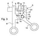
組立の簡素化のために、マウント位置の保持、つまり図1に従った可動握りレバー10の位置の保持を保証するために、握り手3には握りバネ13が備えられており、この握りバネは図の簡素化のために図1及び2では省略されているが、図3では見て取れる。 In order to simplify the assembly, the
図3には、可動握りレバー10が同じ旋回位置にある、図1に示された握り手3が示されているが、拡大図であり、図1では図の簡素化のために省略されたいくつかの詳細が追加されている。 FIG. 3 shows the
図3に示されたように、握りバネ13は軸9の回りに巻かれた、2つの自由端14及び15を備えたコイルバネとして形成されている。その中の自由な端部14は、2つの方向に固定された、対になった止め具16に保持されており、この止め具は不動の握りレバー8又は握りボディ7に固定されている。もう一方の端部15にはストッパー17に対する握りバネ13の圧力がかかり、このストッパーは運動要素18の端部に形成されており、この運動要素はアームが2つある旋回レバーとして、軸19の周りを旋回可能に可動握りレバー10に支承されている。 As shown in FIG. 3, the gripping
握りバネ13は、一方で止め具16によって握りレバー8を支え、他方でストッパー17によって可動握りレバー10を支えている。これはしかし、図3に示されたようにストッパー17が握りバネ13の自由な端部15とかみ合っている限りにおいてのみである。 On the one hand, the
図4に示されたように、運動要素18において、ストッパー17の反対側にある運動要素18のかみ合い端部20が操作ロッド5に当たり得る。このことは可動握りレバー10が図3に示されたマウント位置から出て、時計回りに旋回すると生じる。図3に示された、運動要素18のかみ合い端部20と操作ロッド5の間にあるわずかな遊びが越えられると、かみ合い端部20は操作ロッド5に当たり、図4に示されたように可動握りレバー10自体がさらに旋回すると、軸19の周りを旋回する。 As shown in FIG. 4, in the
図4には、可動握りレバー10自体が時計回りに旋回すると、かみ合い端部20が操作ロッド5に当たることにより、図3及び図4の比較で示されるように、運動要素18が可動握りレバー10に対して反時計回りに旋回されることが示されている。その際ストッパー17は握りバネ13の自由な端部15とのかみ合いから外れる。したがってこの自由な端部15は、図4に示されるように自由である。ここで握りバネ13は可動握りレバー10へかける力はなく、可動握りレバーはここで無力で可動である。 In FIG. 4, when the
図3及び図4の運動要素18は、テンションスプリング21によって圧縮応力がかけられ、このテンションスプリングは運動要素18を時計回り方向に圧縮応力をかけている。運動要素10が図4の旋回位置から再び図3に示されたマウント位置へ旋回して戻されると、運動要素18のかみ合い端部20は操作ロッド5とかみ合う。この運動要素18は、ここでテンションスプリング21によって時計回りに旋回され、及び再びストッパー17が握りバネ13の自由な端部15を支持し得る、図3に示されている位置に来る。 The
図3及び図4に示されたように、図3の位置では作動解除とはならない作動解除装置が作り出される。握りバネ13は、作動解除装置のこの位置では、一方が不動の握りレバー8に、他方が可動握りレバー10に支持され、及びこれが可動握りレバー10の旋回から見て反時計回りに作用し、その結果可動握りレバー10は、図3に示された位置、つまり末端部11がマウント12とかみ合うようにすることが可能なマウント位置にされる。執刀医が鉗子を手に持ち、握りピース8及び10を互いに合わせるように動かして最初の試験操作を行うと、図4に従い、記述されたようにストッパー17を持上げることによって握りバネ13が解放される、鉗子はここで握りバネ13の力から自由に操作される。 As shown in FIGS. 3 and 4, a deactivation device is created that does not deactivate in the position of FIG. At this position of the deactivation device, the
図1〜図4に示された鉗子の第一の実施形態では、握りバネ13によって可動握りレバー10がマウント位置に保持される、すなわち可動握りレバー10が動いているときも、操作ロッド5がそこにない限りにおいて、保持される。操作ロッドが来るとすぐに可動握りレバー10の最初の動きによって運動要素18のかみ合い端部20が操作ロッド5に当たる。示された作動解除装置は、ここでストッパー17をかみ合っていない状態にする。握りバネ13はここで作動解除になる。 In the first embodiment of the forceps shown in FIGS. 1 to 4, the
第二の実施形態(図5〜8)
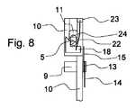
図5〜図8は、第二の実施形態の握り手3を示している。その際図5は、握り手を図1の旋回位置、つまりマウント位置に及び図7は図2に従った旋回位置の握り手を示している。図6及び図8は、それぞれその断面図である。これらの図では、可能な限り前述の実施形態の符号が使用されている。Second embodiment (FIGS. 5 to 8)
5-8 has shown the
図5及び図6は、運動要素18を備えた作動解除装置を示しており、この場合、自由な端部に板バネ22が固定され、この板バネはその不動の端部で、保持ピース23によって可動握りレバー10に固定されている。板バネ22は、その板面の1つの面で軸19に対して横向きに伸びている。したがって運動要素18は、図5及び図6で示されたように、板バネ22が図5又は図6の図面に対して横向きの方向に変形することによって、右から左へ動かされる。その際図6は、運動要素18に力が作用していない場合、ノーマル状態を示している。運動要素18が自由で、図6に示されたように、可動握りレバー10の面からいくらか突き出している場合、握りバネ13の自由な端部15はストッパー17として機能する運動要素18の突き出た角にかみ合う。 FIGS. 5 and 6 show a deactivation device with a
図7及び図8は、同じ、旋回した位置の可動の握り要素10を示している。旋回によって、図7及び図8に示されたように運動要素18は操作ロッド5に対して押された。その際、図6と比較すると、傾斜面24が操作ロッド5とかみ合い、運動要素18と操作ロッド5の間の相対運動によって、側方に、図8の位置へ動かされた。図8と図6を比較すると、このことによって運動要素18が左へ動かされ、その結果もはや可動握りレバー10の面より上に突き出ていないことがわかる。 FIGS. 7 and 8 show the movable
これによって、図7及び8に示されたように、握りバネ13の自由な端部15は解放される。その結果としてここでは、握りバネ13によって再び可動握りレバー10が力の適用から自由に動き得る。図6及び図8には図を簡素化するために不動の握りレバー8は省略されていることを、完全性のために言及しておく。 This releases the
第三の実施形態(図9〜11)
図9〜図11では、作動解除装置の第三の変形例を備えた握り手3の第三の実施形態が示されている。ここでも、可能な限り同じ部品と符号が使用されている。Third embodiment (FIGS. 9 to 11)
In FIGS. 9-11, 3rd embodiment of the
図9及び図10では、握り手3は可動握りレバー10が同じ旋回位置、つまりマウント位置、すなわち図1に従った位置にある。しかし図9では、操作ロッド5が遠位の方向にいくらか引き戻され、その結果末端部11はマウント12とかみ合う寸前である。図10は、マウント12内の末端部11と最終的に組み立てられた位置にある操作ロッド5を示している。 In FIGS. 9 and 10, the
図11は、図10の矢線11−11での、挿入された末端部11を備えた、可動握りレバー10内のマウント12の断面図を示しており、この末端部は普通の球形に形成されており、操作ロッド5の遠位の端部にある。マウント12の範囲には、図11に示されたように、可動握りレバー10内に横向きに伸びる空洞25が形成され、この空洞は片側が開いている。空洞内には運動要素18が横向きにスライド可能に支承されている。運動要素18では、ここでもやはり傾斜面24を形成している。末端部11が操作ロッド5の方向に、矢印方向に、図11に示されたその停止位置にスライドされると、横向きスライダーとして形成された運動要素18は矢印方向に空洞25から押し出される。 FIG. 11 shows a cross-sectional view of the
図9〜図11に示された作動解除装置の実施形態では、ストッパー17は、可動握りレバーのところで、握りバネ13の自由な端部15に対して押しつけられ、傾斜路形状の隆起部として可動握りレバー10の表面に形成される。図9では、握りバネ13の自由な端部15がストッパー17に当たっている。図11では、自由端15のこの状態は破線で示されている。この状態は運動要素18が空洞25内に入ってきて、可動握りレバー10の表面より上に出ていない場合にのみ可能である。 In the embodiment of the deactivation device shown in FIGS. 9 to 11, the
末端部11はマウント12内に挿入され、それによって運動要素18が空洞25から押し出され、こうして握りバネの自由な端部15が運動要素18から外へ押され、ここで引かれた実線で図11に示された位置に到達し、この位置は図10にも示されている。ここで握りバネ13はもはや可動の握り要素10を支えておらず、握り手はそれゆえに無力の状態で操作され得る。握りバネは作動解除装置によって作動解除される。 The
第四の実施形態(図12)
図12には図11の変形形態が示されている。握りバネ13の自由な端部15は、ここでは可動握りレバー10の側面から突き出たストッパー17の後ろにあり、このストッパーはスライダーとして形成された運動要素18の一部であり、この運動要素はこの場合、図11の実施例と類似して横向きにスライド可能に配置されており、及び同様に傾斜面24を備えており、この傾斜面は操作ロッド5を矢印方向にスライドする際に運動要素18が矢印方向に動くように形成されている。その際ストッパー17は、可動握りレバー10の側面の下まで引き戻され、その結果握りバネの自由な端部15が解放される。したがって作動解除装置の本実施形態でも、末端部11がマウント12内にある位置で操作ロッド5が動く場合に、バネ13の可動握りレバー10とのかみ合いの作動解除が達成される。Fourth embodiment (FIG. 12)
FIG. 12 shows a modification of FIG. The
図12の運動要素18はそのストッパー17により、本実施形態で板バネ27によって作動位置に押され、この位置ではストッパー17が突き出ており、それによってストッパーとして機能できる。作動解除のために、操作ロッド5の末端部11は傾斜面24に当たって、運動要素18を板バネ27の力に反して下側へ押す。板バネ27は保持ピース28及び29に固定され、この保持ピースは片方が可動握りレバー10に、もう片方が運動要素18に固定されている。 The
第五の実施形態(図13)
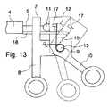
図13は、図1に従った位置にある握り手3の、本発明の第五の実施形態の側面図である。図2に従った、可動握りレバー10の旋回位置は、図13では破線で記載されている。ここでもやはり、可能な限り、同じ部品が図示され、同じ符号が使用されている。Fifth embodiment (FIG. 13)
FIG. 13 is a side view of the fifth embodiment of the present invention of the
図13には、握りボディ7から柄4が連結解除され、同様にマウント12から末端部11が連結解除されていることが示されている。ここには、柄4が操作ロッド5及び末端部11と連結するために握り手3に取り付ける位置が示されている。その際柄4が図13に示された位置から、近位の方向に、つまり右に、握りボディ7に向かって動かされる。その際柄はその近位の正面で可動部材18の遠位の端部に当たり、この端部はこの場合ロッドとして形成されており、このロッドはその縦伸びの方向に、握りボディ7内で縦方向にスライド可能に支承されている。 FIG. 13 shows that the
図13では、引かれた破線で示された運動要素18の位置で、この柄がその近位の側の端部で握りバネ13の自由な端部15と当たっている。ここで柄4は連結のためにさらに近位に、握りボディ7まで動かされ、それによって運動要素18も図13に破線で示されたように、近位にスライドされる。その際運動要素18はバネ13の自由な端部15をつかみ、端部15を図13に破線で示された位置にもってくる。その際握りバネ13の自由な端部15は、可動握りレバー10のストッパー17から遠ざかる。ここで可動握りレバー10はそのストッパー17と共に自由であり得、握りバネ13の力の介入なしに、時計回りに図13に破線で示された位置まで旋回される。 In FIG. 13, the handle hits the
作動解除装置の第五の実施形態でも、末端部11が可動握りレバー10のマウント12に連結する際、運動要素18のスライドによって握りバネ13が作動解除されることが達成され、その際本実施形態では、運動要素18が直接バネに作用し、バネの自由な端部15がバネの圧縮応力がかかっている状態でかみ合いから押し外されることが達成される。 The fifth embodiment of the deactivation device also achieves the deactivation of the
図13を見ると、柄4が連結を外されると作動解除装置がすぐに再びオフの状態になることはすぐに明らかである。握りバネ13の自由な端部15は、端部側で運動要素18が押し戻され、その結果バネは再びストッパー17とかみ合う。
Looking at FIG. 13, it is readily apparent that when the
Claims (14)
Translated fromJapanese握りボディ(7)と、前記握りボディに不動に形成された固定の握りレバー(8)と、前記握りボディ(7)に可動に配置された可動握りレバー(10)と、前記柄内を通り抜け、前記柄(4)の遠位の端部に配置されたエンドエフェクタ(6)を操作する操作ロッド(5)の近位の末端部(11)を備え、前記可動握りレバー(10)に配置されたマウント(12)と、を有し、
前記マウント(12)が、前記可動握りレバー(10)のマウント位置で、前記柄(4)を前記握り手(3)へ取り付けるために前記末端部(11)を収容するように形成され、又は、前記握り手(3)から前記柄(4)を取り外すために前記末端部(11)を解放するために形成されており、
前記握り手は、さらに、握りバネ(13)を有し、
前記握りバネは、前記操作ロッド(5)が取り付けられていない場合に、前記握りバネの一方端では、前記固定の握りレバー(8)又は前記握りボディ(7)で支持し、他方端では、前記可動握りレバー(10)のストッパー(17)で支持した状態で、前記可動握りレバーが前記マウント位置に動くように、前記可動握りレバー(10)に力を加えるようにした握り手において、
前記握り手(3)は、作動解除装置を備え、
前記作動解除装置は、前記握り手(3)に前記操作ロッド(5)が取り付けられる際、前記可動握りレバー(10)の力の適用を前記握りバネ(13)によって作動解除するように構成されていることを特徴とする握り手。A hand grip (3) of a surgical instrument (1) with a handle (4),
A grip body (7), a fixed grip lever (8) formed immovably on the grip body, a movable grip lever (10) movably disposed on the grip body (7), and passing through the handle A proximal end (11) of an operating rod (5) for manipulating an end effector (6) disposed at the distal end of the handle (4) and disposed on the movable grip lever (10) A mounted mount (12),
The mount (12) is configured to receive the distal end (11) for mounting the handle (4) to the grip (3) at the mount position of the movable grip lever (10); or , Formed to release the end (11) to remove the handle (4) from the hand grip (3),
The hand grip further comprises a grip spring (13),
When the operating rod (5) is not attached, the grip spring is supported by the fixed grip lever (8) or the grip body (7) at one end of the grip spring, and at the other end, In a gripping hand in which a force is applied to the movable gripping lever (10) so that the movable gripping lever moves to the mount position while being supported by a stopper (17) of the movable gripping lever (10),
Said hand grip (3) comprises an actuation release device;
The operation release device is configured to release the application of the force of the movable grip lever (10) by the grip spring (13) when the operating rod (5) is attached to the grip hand (3). A handgrip characterized by
前記運動要素は、作動解除位置と非作動解除位置の間を可動に配置されていることを特徴とする、請求項1に記載の握り手。The deactivation device comprises a movement element (18) for producing deactivation;
The hand grip according to claim 1, wherein the movement element is movably disposed between an operation release position and a non-operation release position.
The movement element (18) is arranged and formed by the movement element (18) so that the grip spring (13) does not engage with the stopper (17) in the deactivation position of the movement element. The handgrip according to any one of claims 2 to 11, characterized in that.
Applications Claiming Priority (3)
| Application Number | Priority Date | Filing Date | Title |
|---|---|---|---|
| DE102011015617ADE102011015617B3 (en) | 2011-03-30 | 2011-03-30 | handle |
| DE102011015617.8 | 2011-03-30 | ||
| PCT/EP2012/000570WO2012130355A1 (en) | 2011-03-30 | 2012-02-08 | Handle |
Publications (2)
| Publication Number | Publication Date |
|---|---|
| JP2014512904Atrue JP2014512904A (en) | 2014-05-29 |
| JP6001637B2 JP6001637B2 (en) | 2016-10-05 |
Family
ID=45688413
Family Applications (1)
| Application Number | Title | Priority Date | Filing Date |
|---|---|---|---|
| JP2014501460AActiveJP6001637B2 (en) | 2011-03-30 | 2012-02-08 | Clasped hands |
Country Status (5)
| Country | Link |
|---|---|
| US (1) | US9433431B2 (en) |
| JP (1) | JP6001637B2 (en) |
| CN (1) | CN103429176B (en) |
| DE (1) | DE102011015617B3 (en) |
| WO (1) | WO2012130355A1 (en) |
Cited By (2)
| Publication number | Priority date | Publication date | Assignee | Title |
|---|---|---|---|---|
| JP2019502514A (en)* | 2015-12-21 | 2019-01-31 | ジャイラス エーシーエムアイ インク | High surface energy part on medical device |
| WO2019069457A1 (en)* | 2017-10-06 | 2019-04-11 | オリンパス株式会社 | Medical apparatus |
Families Citing this family (3)
| Publication number | Priority date | Publication date | Assignee | Title |
|---|---|---|---|---|
| US9131950B2 (en)* | 2011-04-15 | 2015-09-15 | Endoplus, Inc. | Laparoscopic instrument |
| HRP20221526T1 (en)* | 2013-08-06 | 2023-02-17 | Universität Basel | Sample holder for an afm |
| WO2017031493A1 (en) | 2015-08-20 | 2017-02-23 | Lsi Solutions, Inc. | Adjustable motion limiter for a minimally invasive surgical device |
Citations (2)
| Publication number | Priority date | Publication date | Assignee | Title |
|---|---|---|---|---|
| US4084594A (en)* | 1976-10-08 | 1978-04-18 | American Hospital Supply Corporation | Surgical instrument and handle assembly therefor |
| US5507297A (en)* | 1991-04-04 | 1996-04-16 | Symbiosis Corporation | Endoscopic instruments having detachable proximal handle and distal portions |
Family Cites Families (8)
| Publication number | Priority date | Publication date | Assignee | Title |
|---|---|---|---|---|
| US5314424A (en)* | 1992-04-06 | 1994-05-24 | United States Surgical Corporation | Surgical instrument locking mechanism |
| US5342391A (en) | 1992-10-06 | 1994-08-30 | Linvatec Corporation | Cleanable endoscopic surgical instrument |
| DE102005011787A1 (en)* | 2005-03-11 | 2006-09-14 | Olympus Winter & Ibe Gmbh | Medical instrument with operating handle |
| CN200977196Y (en) | 2006-10-11 | 2007-11-21 | 徐天松 | Rotary dismantling rongeur |
| CN200970253Y (en) | 2006-11-24 | 2007-11-07 | 徐生源 | Detachable clamp |
| CN201091596Y (en)* | 2007-11-23 | 2008-07-30 | 徐生源 | Detachable and disposable operating forceps |
| CN201211234Y (en) | 2008-05-13 | 2009-03-25 | 徐天松 | Handle of medical biclamp |
| CN201211231Y (en) | 2008-05-13 | 2009-03-25 | 徐天松 | Tongs handles of celioscope operation forceps |
- 2011
- 2011-03-30DEDE102011015617Apatent/DE102011015617B3/enactiveActive
- 2012
- 2012-02-08USUS14/003,356patent/US9433431B2/enactiveActive
- 2012-02-08WOPCT/EP2012/000570patent/WO2012130355A1/enactiveApplication Filing
- 2012-02-08JPJP2014501460Apatent/JP6001637B2/enactiveActive
- 2012-02-08CNCN201280012647.5Apatent/CN103429176B/enactiveActive
Patent Citations (2)
| Publication number | Priority date | Publication date | Assignee | Title |
|---|---|---|---|---|
| US4084594A (en)* | 1976-10-08 | 1978-04-18 | American Hospital Supply Corporation | Surgical instrument and handle assembly therefor |
| US5507297A (en)* | 1991-04-04 | 1996-04-16 | Symbiosis Corporation | Endoscopic instruments having detachable proximal handle and distal portions |
Cited By (4)
| Publication number | Priority date | Publication date | Assignee | Title |
|---|---|---|---|---|
| JP2019502514A (en)* | 2015-12-21 | 2019-01-31 | ジャイラス エーシーエムアイ インク | High surface energy part on medical device |
| WO2019069457A1 (en)* | 2017-10-06 | 2019-04-11 | オリンパス株式会社 | Medical apparatus |
| JPWO2019069457A1 (en)* | 2017-10-06 | 2020-10-22 | オリンパス株式会社 | Medical equipment |
| US11589883B2 (en) | 2017-10-06 | 2023-02-28 | Olympus Corporation | Medical instrument |
Also Published As
| Publication number | Publication date |
|---|---|
| US9433431B2 (en) | 2016-09-06 |
| US20130345743A1 (en) | 2013-12-26 |
| CN103429176A (en) | 2013-12-04 |
| CN103429176B (en) | 2016-01-06 |
| JP6001637B2 (en) | 2016-10-05 |
| WO2012130355A1 (en) | 2012-10-04 |
| DE102011015617B3 (en) | 2012-06-14 |
Similar Documents
| Publication | Publication Date | Title |
|---|---|---|
| CN100563585C (en) | Be particularly useful for the instrument of laparoscopic surgery | |
| JP6609699B2 (en) | Partially disposable surgical clip applier for endoscope | |
| ATE446054T1 (en) | MEDICAL INSTRUMENT FOR GRABING AN OBJECT, IN PARTICULAR A NEEDLE HOLDER | |
| JP6001637B2 (en) | Clasped hands | |
| AU2011201242B2 (en) | Surgical instrument, particularly electrosurgical instrument | |
| AU2012302365B2 (en) | A surgical suture apparatus | |
| US20060206144A1 (en) | Medical instrument with actuating handle | |
| JP2014527422A (en) | Laparoscopic surgery | |
| US9827141B2 (en) | Systems and techniques for tissue manipulation during ocular surgery | |
| CA2482660A1 (en) | Actuation mechanism for flexible endoscopic device | |
| EP3841991B1 (en) | Laparoscopic instrument | |
| EP3610806A1 (en) | Bilateral spring for surgical instruments and surgical instruments including the same | |
| JP6211596B2 (en) | Toggle ergonomic surgical instrument | |
| JP6161790B2 (en) | Ergonomic locking mechanism | |
| JP6126304B2 (en) | Forceps with continuous latch | |
| JP2013526362A (en) | Surgical forceps for venectomy | |
| CN202843708U (en) | Laparoscope cyst separation forceps | |
| RU222611U1 (en) | SURGICAL INSTRUMENT WITH KREMALIER LOCK | |
| EP3518723B1 (en) | A set comprising an endoscope and a work tool unit | |
| JP2015526180A (en) | Surgical forceps |
Legal Events
| Date | Code | Title | Description |
|---|---|---|---|
| A621 | Written request for application examination | Free format text:JAPANESE INTERMEDIATE CODE: A621 Effective date:20140814 | |
| A131 | Notification of reasons for refusal | Free format text:JAPANESE INTERMEDIATE CODE: A131 Effective date:20150414 | |
| A977 | Report on retrieval | Free format text:JAPANESE INTERMEDIATE CODE: A971007 Effective date:20150417 | |
| A521 | Request for written amendment filed | Free format text:JAPANESE INTERMEDIATE CODE: A523 Effective date:20150709 | |
| A131 | Notification of reasons for refusal | Free format text:JAPANESE INTERMEDIATE CODE: A131 Effective date:20160105 | |
| A521 | Request for written amendment filed | Free format text:JAPANESE INTERMEDIATE CODE: A523 Effective date:20160331 | |
| TRDD | Decision of grant or rejection written | ||
| A01 | Written decision to grant a patent or to grant a registration (utility model) | Free format text:JAPANESE INTERMEDIATE CODE: A01 Effective date:20160805 | |
| A61 | First payment of annual fees (during grant procedure) | Free format text:JAPANESE INTERMEDIATE CODE: A61 Effective date:20160901 | |
| R150 | Certificate of patent or registration of utility model | Ref document number:6001637 Country of ref document:JP Free format text:JAPANESE INTERMEDIATE CODE: R150 | |
| R250 | Receipt of annual fees | Free format text:JAPANESE INTERMEDIATE CODE: R250 | |
| R250 | Receipt of annual fees | Free format text:JAPANESE INTERMEDIATE CODE: R250 | |
| R250 | Receipt of annual fees | Free format text:JAPANESE INTERMEDIATE CODE: R250 | |
| R250 | Receipt of annual fees | Free format text:JAPANESE INTERMEDIATE CODE: R250 | |
| R250 | Receipt of annual fees | Free format text:JAPANESE INTERMEDIATE CODE: R250 | |
| R250 | Receipt of annual fees | Free format text:JAPANESE INTERMEDIATE CODE: R250 | |
| R250 | Receipt of annual fees | Free format text:JAPANESE INTERMEDIATE CODE: R250 |