JP2014512004A - Electrochemical energy accumulator leak test apparatus and method - Google Patents
Electrochemical energy accumulator leak test apparatus and methodDownload PDFInfo
- Publication number
- JP2014512004A JP2014512004AJP2014503023AJP2014503023AJP2014512004AJP 2014512004 AJP2014512004 AJP 2014512004AJP 2014503023 AJP2014503023 AJP 2014503023AJP 2014503023 AJP2014503023 AJP 2014503023AJP 2014512004 AJP2014512004 AJP 2014512004A
- Authority
- JP
- Japan
- Prior art keywords
- battery
- housing
- unit
- gas concentration
- electrochemical energy
- Prior art date
- Legal status (The legal status is an assumption and is not a legal conclusion. Google has not performed a legal analysis and makes no representation as to the accuracy of the status listed.)
- Ceased
Links
- 238000000034methodMethods0.000titleclaimsabstractdescription14
- 238000012360testing methodMethods0.000titleclaimsabstractdescription13
- 238000001514detection methodMethods0.000claimsabstractdescription64
- 238000011156evaluationMethods0.000claimsabstractdescription32
- 229910044991metal oxideInorganic materials0.000claimsabstractdescription23
- 150000004706metal oxidesChemical class0.000claimsabstractdescription23
- 239000011230binding agentSubstances0.000claimsabstractdescription9
- 239000003792electrolyteSubstances0.000claimsdescription8
- 239000002904solventSubstances0.000claimsdescription8
- 238000010998test methodMethods0.000claimsdescription3
- 230000003213activating effectEffects0.000claimsdescription2
- 239000007789gasSubstances0.000description57
- 239000007767bonding agentSubstances0.000description19
- 239000008151electrolyte solutionSubstances0.000description9
- 230000007246mechanismEffects0.000description8
- 239000000203mixtureSubstances0.000description6
- MWUXSHHQAYIFBG-UHFFFAOYSA-NNitric oxideChemical compoundO=[N]MWUXSHHQAYIFBG-UHFFFAOYSA-N0.000description5
- 238000012544monitoring processMethods0.000description5
- CURLTUGMZLYLDI-UHFFFAOYSA-NCarbon dioxideChemical compoundO=C=OCURLTUGMZLYLDI-UHFFFAOYSA-N0.000description4
- 239000000567combustion gasSubstances0.000description4
- 230000006866deteriorationEffects0.000description4
- 239000002360explosiveSubstances0.000description4
- 239000007788liquidSubstances0.000description4
- BASFCYQUMIYNBI-UHFFFAOYSA-NplatinumChemical compound[Pt]BASFCYQUMIYNBI-UHFFFAOYSA-N0.000description4
- 239000012491analyteSubstances0.000description3
- 230000010287polarizationEffects0.000description3
- 125000006850spacer groupChemical group0.000description3
- 239000000126substanceSubstances0.000description3
- UGFAIRIUMAVXCW-UHFFFAOYSA-NCarbon monoxideChemical compound[O+]#[C-]UGFAIRIUMAVXCW-UHFFFAOYSA-N0.000description2
- 230000002159abnormal effectEffects0.000description2
- 239000002250absorbentSubstances0.000description2
- 230000002745absorbentEffects0.000description2
- 229910002092carbon dioxideInorganic materials0.000description2
- 239000001569carbon dioxideSubstances0.000description2
- 229910002091carbon monoxideInorganic materials0.000description2
- 230000015556catabolic processEffects0.000description2
- 239000000919ceramicSubstances0.000description2
- 230000008859changeEffects0.000description2
- 238000000354decomposition reactionMethods0.000description2
- 238000006731degradation reactionMethods0.000description2
- 238000010586diagramMethods0.000description2
- 239000000446fuelSubstances0.000description2
- 229910001416lithium ionInorganic materials0.000description2
- 239000000463materialSubstances0.000description2
- 239000002082metal nanoparticleSubstances0.000description2
- 239000002105nanoparticleSubstances0.000description2
- 229910052697platinumInorganic materials0.000description2
- 229920000642polymerPolymers0.000description2
- BVKZGUZCCUSVTD-UHFFFAOYSA-LCarbonateChemical compound[O-]C([O-])=OBVKZGUZCCUSVTD-UHFFFAOYSA-L0.000description1
- UFHFLCQGNIYNRP-UHFFFAOYSA-NHydrogenChemical compound[H][H]UFHFLCQGNIYNRP-UHFFFAOYSA-N0.000description1
- HBBGRARXTFLTSG-UHFFFAOYSA-NLithium ionChemical compound[Li+]HBBGRARXTFLTSG-UHFFFAOYSA-N0.000description1
- 230000009471actionEffects0.000description1
- 230000001588bifunctional effectEffects0.000description1
- 239000006229carbon blackSubstances0.000description1
- 230000009849deactivationEffects0.000description1
- 230000008020evaporationEffects0.000description1
- 238000001704evaporationMethods0.000description1
- 239000000383hazardous chemicalSubstances0.000description1
- 231100000206health hazardToxicity0.000description1
- 239000001257hydrogenSubstances0.000description1
- 229910052739hydrogenInorganic materials0.000description1
- 238000004519manufacturing processMethods0.000description1
- 238000005259measurementMethods0.000description1
- 238000003032molecular dockingMethods0.000description1
- 230000003647oxidationEffects0.000description1
- 238000007254oxidation reactionMethods0.000description1
- 230000008569processEffects0.000description1
- 230000001681protective effectEffects0.000description1
- 230000008439repair processEffects0.000description1
- 230000035807sensationEffects0.000description1
- 230000005236sound signalEffects0.000description1
Images


Classifications
- H—ELECTRICITY
- H01—ELECTRIC ELEMENTS
- H01M—PROCESSES OR MEANS, e.g. BATTERIES, FOR THE DIRECT CONVERSION OF CHEMICAL ENERGY INTO ELECTRICAL ENERGY
- H01M10/00—Secondary cells; Manufacture thereof
- H01M10/42—Methods or arrangements for servicing or maintenance of secondary cells or secondary half-cells
- H01M10/4228—Leak testing of cells or batteries
- H—ELECTRICITY
- H01—ELECTRIC ELEMENTS
- H01M—PROCESSES OR MEANS, e.g. BATTERIES, FOR THE DIRECT CONVERSION OF CHEMICAL ENERGY INTO ELECTRICAL ENERGY
- H01M10/00—Secondary cells; Manufacture thereof
- H01M10/42—Methods or arrangements for servicing or maintenance of secondary cells or secondary half-cells
- H01M10/4235—Safety or regulating additives or arrangements in electrodes, separators or electrolyte
- H—ELECTRICITY
- H01—ELECTRIC ELEMENTS
- H01M—PROCESSES OR MEANS, e.g. BATTERIES, FOR THE DIRECT CONVERSION OF CHEMICAL ENERGY INTO ELECTRICAL ENERGY
- H01M10/00—Secondary cells; Manufacture thereof
- H01M10/42—Methods or arrangements for servicing or maintenance of secondary cells or secondary half-cells
- H01M10/4285—Testing apparatus
- H—ELECTRICITY
- H01—ELECTRIC ELEMENTS
- H01M—PROCESSES OR MEANS, e.g. BATTERIES, FOR THE DIRECT CONVERSION OF CHEMICAL ENERGY INTO ELECTRICAL ENERGY
- H01M6/00—Primary cells; Manufacture thereof
- H01M6/50—Methods or arrangements for servicing or maintenance, e.g. for maintaining operating temperature
- H01M6/5083—Testing apparatus
- H—ELECTRICITY
- H01—ELECTRIC ELEMENTS
- H01M—PROCESSES OR MEANS, e.g. BATTERIES, FOR THE DIRECT CONVERSION OF CHEMICAL ENERGY INTO ELECTRICAL ENERGY
- H01M2200/00—Safety devices for primary or secondary batteries
- H—ELECTRICITY
- H01—ELECTRIC ELEMENTS
- H01M—PROCESSES OR MEANS, e.g. BATTERIES, FOR THE DIRECT CONVERSION OF CHEMICAL ENERGY INTO ELECTRICAL ENERGY
- H01M6/00—Primary cells; Manufacture thereof
- H01M6/50—Methods or arrangements for servicing or maintenance, e.g. for maintaining operating temperature
- H01M6/5044—Cells or batteries structurally combined with cell condition indicating means
- Y—GENERAL TAGGING OF NEW TECHNOLOGICAL DEVELOPMENTS; GENERAL TAGGING OF CROSS-SECTIONAL TECHNOLOGIES SPANNING OVER SEVERAL SECTIONS OF THE IPC; TECHNICAL SUBJECTS COVERED BY FORMER USPC CROSS-REFERENCE ART COLLECTIONS [XRACs] AND DIGESTS
- Y02—TECHNOLOGIES OR APPLICATIONS FOR MITIGATION OR ADAPTATION AGAINST CLIMATE CHANGE
- Y02E—REDUCTION OF GREENHOUSE GAS [GHG] EMISSIONS, RELATED TO ENERGY GENERATION, TRANSMISSION OR DISTRIBUTION
- Y02E60/00—Enabling technologies; Technologies with a potential or indirect contribution to GHG emissions mitigation
- Y02E60/10—Energy storage using batteries
Landscapes
- Engineering & Computer Science (AREA)
- Manufacturing & Machinery (AREA)
- Chemical & Material Sciences (AREA)
- Chemical Kinetics & Catalysis (AREA)
- Electrochemistry (AREA)
- General Chemical & Material Sciences (AREA)
- Secondary Cells (AREA)
- Battery Mounting, Suspending (AREA)
- Examining Or Testing Airtightness (AREA)
- Connection Of Batteries Or Terminals (AREA)
Abstract
Translated fromJapaneseDescription
Translated fromJapanese本発明は、電気化学的エネルギーアキュムレータの漏れ試験装置および方法に関し、このアキュムレータは、バッテリ個別セルとして、もしくは、並列および/または直列に接続された複数のバッテリ個別セルを備えるバッテリとして形成され、少なくとも1つの検知ユニットが設けられており、この検知ユニットを使ってハウジング内のガス濃度を検知することができる。 The present invention relates to a leak test apparatus and method for an electrochemical energy accumulator, the accumulator being formed as a battery individual cell or a battery comprising a plurality of battery individual cells connected in parallel and / or in series, at least One detection unit is provided, and this detection unit can be used to detect the gas concentration in the housing.
特許文献1から、バッテリ内の漏れを点検するシステムおよびバッテリの漏れを検知する方法が知られている。このシステムは、ガス感受性のナノ粒子構造を備えるガスセンサを有し、このナノ粒子構造は、二官能性または多官能性有機分子に結合した金属ナノ粒子を有している。ガス感受性ナノ粒子構造は金属ナノ粒子/有機結合構造であり、半導体ポリマー構造および/またはポリマー/カーボンブラック結合構造と組み合わされている。この構造は、揮発性薬品に対して非常に高い感受性を有している。ガスセンサは、センサの導電率、容量、インダクタンス、誘電体誘導率、分極、インピーダンス、熱容量または温度の検体誘発変化に基づいて作動するセンサである。この方法は、ガス感受性ガスセンサがバッテリの近くに配置され、異常のあるバッテリを示す、ガスセンサ内の導電率、容量、インダクタンス、誘電体誘導率、分極、インピーダンス、熱容量または温度の検体誘発変化を検知する。ガスセンサ内で導電率、容量、インダクタンス、誘電体誘導率、分極、インピーダンス、熱容量または温度の検体誘起変化が検知されると、光による信号、音による信号および/またはデータ信号が出力される。次の手順では、検出された異常なバッテリが自動的に選び出される。 From
本発明の課題は、従来技術と比べ改善された電気化学的エネルギーアキュムレータの漏れ試験装置および方法を提供することであり、このアキュムレータは、バッテリ個別セルとして、もしくは、並列および/または直列に接続された複数のバッテリ個別セルを備えるバッテリとして形成されている。 It is an object of the present invention to provide an electrochemical energy accumulator leak testing apparatus and method which is improved compared to the prior art, which accumulator is connected as a battery individual cell or in parallel and / or in series. It is formed as a battery provided with a plurality of individual battery cells.
この課題は、本発明に基づき、装置に関して、請求項1に記載の特徴によって解決され、方法に関しては請求項7に記載の特徴によって解決される。
電気化学的エネルギーアキュムレータの漏れ試験装置および方法の場合、このアキュムレータは、バッテリ個別セルとして、もしくは、並列および/または直列に接続された複数のバッテリ個別セルを備えるバッテリとして形成され、少なくとも1つの検知ユニットが設けられており、この検知ユニットを使ってハウジング内のガス濃度を検知することができる。本発明に基づき、このハウジングはバッテリハウジングとして形成され、閉鎖可能であり、その際、検知ユニットは金属酸化物センサであり、この金属酸化物センサは評価ユニットに接続されており、検知されたガス濃度に応じて、例えば電気化学的エネルギーアキュムレータを作動停止にするため、及び/又は接合剤放出ユニットを作動するための制御信号が、評価ユニットを用いて自動的に生成可能である。This problem is solved according to the invention by the features of
In the case of an electrochemical energy accumulator leak test apparatus and method, the accumulator is formed as a battery individual cell or as a battery comprising a plurality of battery individual cells connected in parallel and / or in series, and at least one sensing A unit is provided, and the gas concentration in the housing can be detected using this detection unit. According to the invention, this housing is formed as a battery housing and can be closed, in which case the detection unit is a metal oxide sensor, which is connected to the evaluation unit and the detected gas Depending on the concentration, for example, a control signal for deactivating the electrochemical energy accumulator and / or activating the binder release unit can be automatically generated using the evaluation unit.
本発明に基づく装置を用いることにより、電気化学的エネルギーアキュムレータを取り扱う人間の安全性が、アキュムレータの作動中および非作動中の両方において特に有利な方法で高められる。バッテリの作動を確実に行えるようにするため、この電気化学的エネルギーアキュムレータは、その気密性に関して少なくとも1つの検知ユニットによって連続的に監視することができる。 By using the device according to the invention, the safety of the person handling the electrochemical energy accumulator is increased in a particularly advantageous manner both during and without operation of the accumulator. In order to ensure that the battery can be operated, the electrochemical energy accumulator can be continuously monitored by at least one sensing unit for its tightness.
電気化学的エネルギーアキュムレータは、好ましくは、電気自動車、ハイブリッド車又は燃料電池で作動する車両の高電圧バッテリであり、バッテリの個別セルは、特にチリウムイオンセルである。 The electrochemical energy accumulator is preferably a high voltage battery of a vehicle operating on an electric vehicle, a hybrid vehicle or a fuel cell, and the individual cell of the battery is in particular a thyllium ion cell.
少なくとも1つの金属酸化物センサの検知信号は評価ユニットに供給可能であるため、引火性の、さらに爆発性のガス組成を検出することができ、それに応じて、人間の安全性に関して少なくとも1つの措置が評価ユニットにより自動的に開始される。 The detection signal of the at least one metal oxide sensor can be supplied to the evaluation unit, so that a flammable and more explosive gas composition can be detected, and accordingly at least one measure regarding human safety. Is automatically started by the evaluation unit.
ガス濃度の検知ユニットである金属酸化物センサは、好ましくはプラチナ微細構造をもつセラミックチップと、例えば還元可能なガス、酸化しやすいガスおよび酸化しにくいガスに対する3つのガス感受性金属酸化物層を備えており、これらの構成部品は、少なくとも部分的にセンサハウジングの中に配置することができる。 The metal oxide sensor, which is a gas concentration sensing unit, preferably comprises a ceramic chip with a platinum microstructure and three gas sensitive metal oxide layers for example for a reducible gas, a oxidizable gas and a non-oxidizable gas. And these components can be at least partially disposed within the sensor housing.
金属酸化物センサの機能方法は、酸化可能な、及び/又は還元可能なガスと接触する際に生じる、ガス感受性金属酸化物の導電率の変化に基づいている。この場合、金属酸化物センサの測定範囲はガスの種類に左右され、相対的な量として百万分の1(parts per million)のガス濃度が検知可能である。 The metal oxide sensor functional method is based on the change in conductivity of the gas sensitive metal oxide that occurs upon contact with an oxidizable and / or reducible gas. In this case, the measurement range of the metal oxide sensor depends on the type of gas, and a gas concentration in parts per million (parts per million) can be detected as a relative amount.
バッテリハウジング内が、少なくとも1つの検知ユニットによって検出可能なガス濃度である場合、バッテリの少なくとも1つのバッテリ個別セルに漏れがあり、電解液および/または揮発性の高い電解液の溶剤成分が流出し、それによって少なくともバッテリ付近にいる人間への危険が存在すると判断することができる。 When the gas concentration in the battery housing is detectable by at least one detection unit, there is a leak in at least one individual battery cell of the battery, and the electrolyte solution and / or the solvent component of the highly volatile electrolyte flow out. Thus, it can be determined that there is a danger to a person at least near the battery.
さらに、金属酸化物センサとして実施されている検知ユニットによって、例えば、バッテリハウジング内で電子機器の火災および/またはケーブル火災が発生した場合には、燃焼ガスを検出し、その検知信号を評価ユニットに送信することができる。このようなケースでは、評価ユニットの制御信号を使って、例えばバッテリを作動停止にすることができる。 Further, when a detection unit implemented as a metal oxide sensor, for example, fires of electronic equipment and / or cable fires occur in the battery housing, the combustion gas is detected and the detection signal is sent to the evaluation unit. Can be sent. In such a case, for example, the battery can be deactivated using the control signal of the evaluation unit.
特に好ましい実施形態では、バッテリハウジング自体に接合剤放出ユニットが配置されており、それにより、接合剤がバッテリハウジング内で放出可能であり、漏れのあるバッテリ個別セルから流出している電解液にバッテリハウジング内で結合させる。従って、電解液がバッテリハウジングから流出し、それによって人間への危険となる可能性がほぼ排除される。 In a particularly preferred embodiment, a bonding agent discharge unit is arranged on the battery housing itself, so that the bonding agent can be discharged in the battery housing and the battery is discharged into the electrolyte flowing from the leaking battery individual cells. Join in the housing. Therefore, the possibility that the electrolyte flows out of the battery housing and thereby poses a danger to humans is almost eliminated.
接合剤放出ユニットは閉鎖可能な開口部を備える容器を有し、評価ユニットは、有利には、開口部を閉鎖する放出機構と接続されている。評価ユニットと放出機構との間の接続により、手動によって操作することなく接合剤放出ユニットを自動的に作動させることが可能である。接合剤は放出され、バッテリハウジング内に分散する。例えば、接合剤は液体の有機物質に用いる液体の吸収剤である。 The bonding agent release unit has a container with a closable opening, and the evaluation unit is advantageously connected to a release mechanism that closes the opening. Due to the connection between the evaluation unit and the release mechanism, it is possible to automatically activate the binder release unit without manual operation. The bonding agent is released and dispersed within the battery housing. For example, the bonding agent is a liquid absorbent used for liquid organic substances.
有利な実施形態においては、光、音および/または触覚による警告信号を出力するための出力ユニットが設けられているため、例えば車両の運転者は、電気化学的エネルギーアキュムレータに危険が存在することに対する警告を受ける。漏れのあるバッテリ個別セルは、漏れがあってもその完全な機能を有することができるため、故障が発見されないままとなる。 In an advantageous embodiment, an output unit is provided for outputting light, sound and / or tactile warning signals, so that, for example, a vehicle driver may be aware that there is a danger in the electrochemical energy accumulator. Get a warning. A leaky battery individual cell can have its full functionality in the presence of a leak, so that no faults remain discovered.
好ましくは、複数の検知ユニットをバッテリハウジングの中に配置することもでき、それによって、複数の電気化学的エネルギーアキュムレータが配置されている場合は、それぞれのアキュムレータに各々1つの検知ユニットが割り当てられる。検知された信号は評価ユニットに送信可能であるため、検知されたガス濃度に基づいて、バッテリハウジング内で、漏れのある電気化学的エネルギーアキュムレータがどこにあるのか、または漏れのあるバッテリ個別セルがどこにあるのかを調べることができるので有利である。 Preferably, a plurality of sensing units can also be arranged in the battery housing, whereby when a plurality of electrochemical energy accumulators are arranged, one sensing unit is assigned to each accumulator. Since the detected signal can be sent to the evaluation unit, where in the battery housing there is a leaking electrochemical energy accumulator or where there is a leaking battery individual cell based on the detected gas concentration It is advantageous because it can be checked whether it exists.
もう1つの有利な実施形態では、検知ユニットがバッテリハウジングの内部スペースにおいて、バッテリ個別セルに接して、および/またはバッテリ個別セルの中に配置されて、ガス濃度を検知する。バッテリ個別セル内に検知ユニットが配置されている場合、このユニット内でガス濃度を検知することができるため、バッテリ個別セルの品質状態およびさらに劣化状態も調べることができる。この場合、バッテリ個別セルの中に配置されている検知ユニットを用いて、電解液の分解物質が検知可能であり、このことからバッテリ個別セルの品質状態ならびに劣化状態を調べることができる。 In another advantageous embodiment, a detection unit is arranged in the interior space of the battery housing in contact with and / or in the battery individual cell to detect the gas concentration. When the detection unit is arranged in the battery individual cell, the gas concentration can be detected in the unit, so that the quality state and further the deterioration state of the battery individual cell can be examined. In this case, the decomposition unit of the electrolytic solution can be detected using the detection unit arranged in the battery individual cell, and from this, the quality state and the deterioration state of the battery individual cell can be examined.
特に、電気化学的エネルギーアキュムレータの品質状態および/または劣化状態に関する情報は、中古品のバッテリ個別セルからバッテリを組み立てる場合に利用できる。さらに、調査された1つまたは複数の品質状態および/または劣化状態は、電気化学的エネルギーアキュムレータの交換、修理、材料の再利用および/または廃棄の際の重要なパラメータである。 In particular, information regarding the quality state and / or degradation state of the electrochemical energy accumulator can be used when assembling a battery from second-hand battery individual cells. Furthermore, the investigated one or more quality and / or degradation conditions are important parameters in the replacement, repair, material reuse and / or disposal of electrochemical energy accumulators.
さらに、この電気化学的エネルギーアキュムレータの漏れ試験方法は、電気化学的エネルギーアキュムレータの製造時にも使用可能である。 Further, this electrochemical energy accumulator leakage test method can also be used when manufacturing an electrochemical energy accumulator.
バッテリハウジングの外部環境に対して、バッテリハウジング内に少なくとも短時間、例えば一定の間隔で技術的に負圧を発生させることも考えられる。このことにより、電気化学的エネルギーアキュムレータに漏れがある場合は、電解液成分の気化を加速させることができる。 It is also conceivable to technically generate a negative pressure in the battery housing at least for a short time, for example at regular intervals, with respect to the external environment of the battery housing. Thereby, when there is a leak in the electrochemical energy accumulator, the evaporation of the electrolyte component can be accelerated.
バッテリ個別セルとして、または並列および/または直列に接続された複数のバッテリ個別セルを備えるバッテリとして形成されている電気化学的エネルギーアキュムレータの漏れ試験方法は、少なくとも1つの検知ユニットによってハウジング内のガス濃度が検知されるようになっている。本発明に基づき、このハウジングはバッテリハウジングとして形成され、閉鎖されており、その際、バッテリハウジング内において、検知ユニットである金属酸化物センサによってガス濃度が検知され、その検知信号が評価ユニットに送信され、検知されたガス濃度に応じて、電気化学的エネルギーアキュムレータをオフにするため、及び/又は接合剤放出ユニットを作動するため、および/または運転者に警告を発するための制御信号が生成される。 An electrochemical energy accumulator leak test method, formed as a battery individual cell or as a battery comprising a plurality of battery individual cells connected in parallel and / or in series, the gas concentration in the housing by at least one detection unit Is to be detected. According to the invention, this housing is formed as a battery housing and is closed, in which the gas concentration is detected by a metal oxide sensor, which is a detection unit, and the detection signal is transmitted to the evaluation unit. Depending on the sensed gas concentration, a control signal is generated to turn off the electrochemical energy accumulator and / or to activate the binder release unit and / or to alert the driver. The
電気化学的エネルギーアキュムレータが車両内に配置されている場合、ガス濃度は、特に有利な方法で連続的に、すなわち車両走行中も、停止中も検知される。 If an electrochemical energy accumulator is arranged in the vehicle, the gas concentration is detected in a particularly advantageous manner continuously, i.e. while the vehicle is running and when it is stopped.
有利な実施形態では、検知ユニットによって揮発性の高い電解液の溶剤成分が検知され、電気化学的エネルギーアキュムレータがリチウムイオンセルまたはリチウムイオンバッテリとして実施されている場合、揮発性の高い溶剤成分は有機カーボネートである。揮発性の高い溶剤成分の検知により、ハウジング内の引火性の、さらには爆発性のガス組成を検出することができる。 In an advantageous embodiment, when the sensing unit detects the solvent component of the highly volatile electrolyte and the electrochemical energy accumulator is implemented as a lithium ion cell or lithium ion battery, the highly volatile solvent component is organic. Carbonate. By detecting a highly volatile solvent component, a flammable or explosive gas composition in the housing can be detected.
この種のガス組成が検出された場合、評価ユニットによって少なくとも1つの警告信号が生成可能であり、出力可能である。引火性の、さらには爆発性のガス組成を検知することができ、それによって、警告信号が生成可能であり、出力できることから、電気化学的エネルギーアキュムレータの付近にいる人間への健康被害が回避される。 If such a gas composition is detected, at least one warning signal can be generated and output by the evaluation unit. It can detect flammable and even explosive gas compositions, which can generate and output warning signals, thereby avoiding health hazards to people in the vicinity of electrochemical energy accumulators. The
特に、有利な方法では、複数の電気化学的エネルギーアキュムレータが配置されている場合、各エネルギーアキュムレータにそれぞれ1つの検知ユニットが金属酸化物センサの形で割り当てられているため、ガス濃度が検知された場合、漏れのある電気化学的エネルギーアキュムレータがどこにあるのか、評価ユニットを用いて調べることができる。この場合、この装置により、漏れのあるバッテリ個別セルの探索が極めて簡単になる。検知ユニットである金属酸化物センサは、寸法が比較的小さく、調達コストも比較的安いため、電気化学的エネルギーアキュムレータの漏れ試験のために複数の検知ユニットをバッテリハウジングの中に配置することが可能である。 In particular, in an advantageous manner, when a plurality of electrochemical energy accumulators are arranged, the gas concentration is detected because one sensing unit is assigned to each energy accumulator in the form of a metal oxide sensor. If so, the evaluation unit can be used to determine where the leaky electrochemical energy accumulator is located. In this case, this device makes it very easy to search for leaky battery individual cells. The sensing unit metal oxide sensor is relatively small in size and relatively inexpensive to procure, allowing multiple sensing units to be placed in the battery housing for leak testing of electrochemical energy accumulators It is.
本発明の実施例を、図に基づいて以下に詳しく説明する。 Embodiments of the present invention will be described in detail below with reference to the drawings.
互いに対応する部品は、全ての図の中で同一の記号が付されている。 Parts corresponding to each other are given the same symbol in all the drawings.
図1は、本発明に基づく、電気化学的エネルギーアキュムレータの漏れ試験装置の断面図を示し、このエネルギーアキュムレータはバッテリ1またはバッテリ個別セル2として形成されている。 FIG. 1 shows a cross-sectional view of an electrochemical energy accumulator leak test apparatus according to the present invention, which is formed as a
バッテリ1は、電気自動車、ハイブリッド車又は燃料電池で作動する車両の高電圧バッテリである。 The
この装置は、バッテリハウジング3として形成されているハウジング、検知ユニット4としての複数の金属酸化物センサ、評価ユニット5、ならびに接合剤放出ユニット6を備えている。 This device comprises a housing formed as a
バッテリハウジング3はボックス型で閉鎖可能に形成され、バッテリハウジング3は閉じられた状態でほぼ気密に実施されている。 The
バッテリハウジング3内には、規定の数のバッテリ個別セル2、7が電気化学的エネルギーアキュムレータとして配置されており、これらのセルは並列および/または直列に互いに接続されている。この場合、バッテリ個別セル2の中には、漏れのあるバッテリ個別セル7がある。 Within the
バッテリ個別セル2、7は、それぞれセルハウジング2.1を有し、この中にはアノード層、カソード層およびそれらの間にあるセパレータ層から成る電極構造(図示されていない)が配置されている。 The
セルハウジング2.1の上端部であるセルカバー2.2内には、少なくとも2つの開口部が取り付けられており、これらの開口部にはバッテリ個別セル2、7の極8がそれぞれ配置されている。 At least two openings are attached in the cell cover 2.2 which is the upper end of the cell housing 2.1, and the
セルハウジング2.1内で、極8の一方は電極コイルのアノード層に接続され、もう一方の極8はカソード層に接続されている。 Within the cell housing 2.1, one of the
バッテリハウジング3の内側の上部には、金属酸化物センサとして実施されている複数の検知ユニット4が配置されており、これらのユニットは、バッテリ監視ユニットの評価ユニット5に接続されている。この場合、検知ユニット4は、好ましくは、バッテリ個別セル2の上方に直接配置され、検知ユニット4の検出面はバッテリ個別セル2の方向に向けられている。 A plurality of
金属酸化物センサとして実施されている検知ユニット4は、詳しく図示されていないセンサハウジングを備え、このハウジング内にはプラチナ微細構造をもつセラミックチップと、好ましくは、還元可能なガスならびに酸化しやすいガスおよび酸化しにくいガスを検知する3つのガス感受性金属酸化物層とが配置されている。 The
さらに、バッテリ個別セル2、7の漏れ試験装置は接合剤放出ユニット6を備え、このユニットは、同様にバッテリハウジング3内に配置されている。 Furthermore, the leak test apparatus for the
接合剤放出ユニット6は容器6.1を備え、この容器内には、接合剤9が、例えば液体の有機物質に用いる液体の吸収剤の形で保存されている。 The bonding
容器6.1の使用に対する代替として、接合剤9を貯蔵するためのカセット又はその他の装置を設けることもできる。 As an alternative to the use of container 6.1, a cassette or other device for storing the
容器6.1は、放出機構6.2によって閉鎖可能な開口部を有し、この開口部にはバルブ6.3が配置されている。このバルブ6.3は、着火式、電気式および/または電磁的に作動可能な放出機構6.2によって開かれる。これにより、接合剤9が容器6.1から放出され、バッテリハウジング3の中へ流出する。電気式作動の場合、例えば容器6.1または配管部分などの規定破断箇所が溶かされ、それによって接合剤9を放出する開口部が開放されるように設けることができる。 The container 6.1 has an opening that can be closed by a discharge mechanism 6.2, in which a valve 6.3 is arranged. This valve 6.3 is opened by an ignition mechanism 6.2 that can be ignited, electrically and / or electromagnetically actuated. As a result, the
バルブ6.3の追加または代替として、ノズル、いわゆるバルブアクチュエータまたはその他の閉鎖可能な装置を容器6.1に配置することもできる。 As an addition or alternative to the valve 6.3, a nozzle, so-called valve actuator or other closable device can also be arranged in the container 6.1.
好ましくは、容器6.1および放出機構6.2がバッテリ監視ユニットの評価ユニット5に接続されている。 Preferably, the container 6.1 and the discharge mechanism 6.2 are connected to the
バッテリ1の作動中ならびに非作動中に、金属酸化物センサとして実施されている検知ユニット4を用いて、バッテリハウジング3内でガス濃度が検知される。 During operation and non-operation of the
漏れのあるバッテリ個別セル7は漏れ部分を有しており、この漏れ部分から、バッテリ個別セル7の電解液10の揮発性の高い溶剤成分が気化する。さらに、バッテリ個別セル2内で優勢となっている許容されない内圧、例えば内部ショートなどによって、図5に詳しく図示されているように、閉鎖エレメント11で閉鎖されている破断解放部2.3が開くおそれがある。破断解放部2.3を開くことによって、セルハウジング2.1が破裂することなく、圧力を制御しながらセルハウジング2.1から圧力を逃すことができる。この破断解放部2.3が閉鎖されなくなった場合、電解液10がセルハウジングから流出し、バッテリ1の周辺にいる人間への危険となる可能性がある。電解液10が流出する場合、揮発性の高い溶剤成分が気化し、その際、これらの成分が検知ユニット4によって検知される。 The leaky battery
電解液10の揮発性の高い溶剤成分が、バッテリハウジング3の上方に配置されている、金属酸化物センサの形での検知ユニット4に接触すると、ガス感受性金属酸化物センサの導電率が変化するため、ガス濃度を検知することができる。すなわち、各検知ユニット4は、その検出面部分でガス濃度を検知する。 When the highly volatile solvent component of the
各検知ユニット4の検知信号は、評価ユニット5に送信され、ガス濃度に関して、保存されている限界値S1〜S3と比較される。Detection signals of the
1つまたは複数の検知されたガス濃度が保存されている第1の限界値S1を超えている場合、評価ユニット5に連結されている出力ユニット(図示されていない)によって第1の制御信号が生成され、この信号によって、光、音および/または触覚による警告信号の出力が作動可能である。 If one or more detected gas concentrations exceed a stored first limit value S1, a first control signal is output by an output unit (not shown) connected to the
バッテリ3と、従ってバッテリ個別セル2の漏れ試験装置とが車両内に配置されている場合、光による警告信号は、好ましくは、インストルメントパネル内に配置されている制御可能な少なくとも1つのランプによって出力される。 If the
音による警告信号は、好ましくは、車両内に配置されているスピーカによって出力され、触覚の警告信号としては、例えばステアリングホイールまたは車両シートを振動させることができる。 The sound warning signal is preferably output by a speaker arranged in the vehicle. As the tactile warning signal, for example, a steering wheel or a vehicle seat can be vibrated.
警告信号の出力によって、運転者はバッテリ1の故障について情報が与えられる。 The driver is informed about the failure of the
検知ユニット4のいずれかで検知されたガス濃度が、評価ユニット5に保存されている第2の限界値S2を超過した場合、評価ユニット5によって第2の制御信号が生成され、この信号はバッテリ監視ユニットに送信される。第2の制御信号によって、バッテリ1は、バッテリ監視ユニットによって自動的に作動停止され、車内および車両のすぐ近くにいる人間への危険を大幅に排除する。保護部が自動的に開くことによって、バッテリ1の電気的作動を中断することも可能である。Detected gas concentration in either the
好ましくは、バッテリ1を作動停止する前に規定時間の範囲内で、これから行われる作動停止プロセスについて、例えば別の音および/または光および/または触覚による警告信号によって自動車の運転者に情報が送られる。これにより、その他の道路利用者を妨げるか、もしくは危険にさらすことなく、例えば路肩など適切な場所に車両を止めることが可能である。 Preferably, information is sent to the driver of the vehicle, for example by another sound and / or light and / or tactile warning signal, about the deactivation process to be performed within a specified time before deactivating the
次に、バッテリ1を専門家が点検し、バッテリ監視ユニットに配置されている診断インタフェースまたはドッキングシステムによって評価ユニット5を読み取ることができる。評価ユニット5内には、各検知ユニット4によって個々に検知されたガス濃度が保存され、読み出すことができるため、検知したガス濃度に基づいて、バッテリハウジング3内で漏れのあるバッテリ個別セル7がどこにあるのかを調べることができる。つまり、いずれかの検知ユニット4が、その他での検知されたガス濃度よりも高い値を有しているガス濃度を検知した場合、漏れのあるバッテリ個別セル7がこの検知ユニット4の検出範囲内にある可能性は比較的高い。漏れのあるバッテリ個別セル7は正常なバッテリ個別セル2と交換し、バッテリ1を再び作動させることが可能である。 The
検知ユニット4のいずれかによって、保存されている第3の限界値S3を超過するガス濃度が検知された場合、第3の制御信号が生成され、接合剤放出ユニット6の放出機構6.2に送信される。第3の制御信号によって、接合剤放出ユニット6が自動的に作動する。放出機構6.2によってバルブ6.3が開かれるため、接合剤9が放出され、バッテリハウジング3の中で分散し、流出している電解液10に結合する。Either by the
さらに、バッテリハウジング3内に配置されている複数の検知ユニット4によって、例えばケーブル火災および/または電子機器火災の際に発生する燃焼ガスも検出されるように設けることができる。燃焼ガスとしては、例えば、一酸化炭素、二酸化炭素および/または水素が検知される。この種の燃焼ガスが検出された場合、好ましくは、もう1つの制御信号が生成され、バッテリ1は、例えば電気的作動を停止するなど、安全な状態にされる。 Further, the plurality of
さらに、この装置によって、バッテリハウジング3内の引火性かつ爆発性のガス組成を検知することも可能である。この種のガス組成が検知された場合、出力ユニットにより、少なくとも1つの警告信号が出力され、好ましくはバッテリ1が作動停止される。 Furthermore, it is possible to detect a flammable and explosive gas composition in the
図2には、バッテリ1のバッテリ個別セル2の漏れ点検試験装置の代替の実施形態が示されている。 FIG. 2 shows an alternative embodiment of a leak check test device for a battery
この場合、この装置は、バッテリハウジング3内に配置されている検知ユニット4を備え、このユニットによってガス濃度が検知される。検知ユニット4は、評価ユニット5に接続されており、このユニットは検知された信号を評価し、保存されている限界値S1、S2の少なくともいずれか一方を上回っている場合は、生成された制御信号によって該当する措置を開始する。図2に基づく装置は、接合剤放出ユニット6を備えていないため、ガス濃度が検知された場合、特に好ましくは、バッテリ1が自動的に作動停止される。 In this case, the device includes a
図3は、互いに直列に接続された6つのバッテリ個別セル2を上から見た図を示し、それぞれ1つの負極8が別のバッテリ個別セル2の正極8に接続されている。 FIG. 3 shows a view of six battery
エッジ側に隣り合って配置されている2つのバッテリ個別セル2には、発生した電圧を取り出すため、一方の極性の直列接続部12がそれぞれ1つ配置され、その直列接続部12には電気負荷13が配置されているため、電気エネルギーが供給される。 In order to take out the generated voltage, two
それぞれのバッテリ個別セル2のセルカバー2.2の上には、検知ユニット4が金属酸化物センサの形で配置されている。バッテリ個別セル2の検知ユニット4は、好ましくは、データバスを介して評価ユニット5に接続されている。この場合、セルカバー2.2上の検知ユニット4は、バッテリハウジング3の上方に配置されている検知ユニット4の追加または代替として設けることができる。 On the cell cover 2.2 of each battery
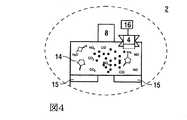
図4は、検知ユニット4を備えるバッテリ個別セル2のセルヘッドの拡大図を示している。 FIG. 4 shows an enlarged view of the cell head of the battery
セルカバー2.2の中には開口部が取り付けられ、この開口部内に、金属酸化物センサの形で検知ユニット4が配置されている。検知ユニット4の検出面は、この場合、セルハウジング2.1内にあり、その際、検出面は超過圧力を調整するためのスペース14内に突き出している。 An opening is mounted in the cell cover 2.2, in which the
例えば、バッテリ個別セル2の中では、バッテリ個別セル2の充電および放電の際にセルハウジング2.1内で発生する熱により、超過圧力が生じる。さらに、プレッシャリリーフバルブをセルカバー2.2に配置することができ、このバルブは、流体技術的にスペース14とも、バッテリ個別セル2の周辺とも接続されている。セルハウジング2.1内で優勢になっている超過圧力を調整するスペース14が不十分な場合、すなわち、超過圧力がセルハウジング2.1には許容できないほど上昇した場合、このプレッシャリリーフバルブが開くことによって、超過圧力が逃がされる。 For example, in the battery
さらに、バッテリ個別セル2のセルヘッドにはスペーサエレメント15があり、これらは、例えばセルハウジング2.1が変形した場合に、電極コイルがセルカバー2.2に接触するのを防止する。セルカバー2.2および電極コイルが接触すると、セルハウジング2.1内でショートが発生するおそれがある。さらに、スペーサエレメント15は、電極コイルとセルカバー2.2との間にスペース14の容積を規定するために用いられる。 Furthermore, the cell head of the battery
セルハウジング2.1内で優勢となっている超過圧力を、スペース14およびプレッシャリリーフバルブによっても逃がすことができない場合、バッテリ個別セル2が破裂し、セルハウジング2.1が突然故障する危険が生じる。例えば、この場合、優勢となっている超過圧力のために、セルハウジング2.1に亀裂が生じるおそれがある。 If the overpressure prevailing in the cell housing 2.1 cannot be released even by the
セルハウジング2.1が制御不能になって破裂するのを回避するため、破裂解放部2.3が設けられている。破裂開口部2.3は例えばダイヤフラムなどの閉鎖エレメント11によって閉鎖されており、セルハウジング2.1内に特定の圧力生じると、図5に詳しく図示されているように、閉鎖エレメントが開くように形成されているため、超過圧力が逃がされる。 In order to prevent the cell housing 2.1 from being out of control and rupturing, a rupture release 2.3 is provided. The rupture opening 2.3 is closed by a
検知ユニット4は制御ユニット16に接続されており、この制御ユニットに検知信号を送信することができる。 The
検知ユニット4の検出面はスペース14の中に突き出しているため、スペース14内にあるガス濃度が検知される。この場合、窒素酸化物、一酸化窒素、一酸化炭素および/または二酸化炭素が電解液の分解成分として検知ユニット4によって検知される。この検知信号が制御ユニット16に送信され、評価される。例えば、制御ユニット16内に限界値が保存されており、この限界値と、検知されたガス濃度におけるそれぞれのガスの割合とが比較される。この比較に基づき、バッテリ個別ユニット2の品質状態が調査される。追加または代替として、バッテリ個別セル2の劣化状態も、検知されたガス濃度に基づいて調べることができる。 Since the detection surface of the
品質状態および/またはバッテリ個別セル2の劣化状態に関する情報は、例えばバッテリ個別セル2の交換、材料の再利用および排気の際などに重要な要素となる。 The information regarding the quality state and / or the deterioration state of the battery
図5は、破断解放部2.3が開いているバッテリ個別セル2の底面部分を示している。電解液10がセルハウジング2.1に関して破断解放部2.3から外へ流出し、その際、接合剤放出ユニット6によって放出された接合剤9が電解液10に結合している。 FIG. 5 shows a bottom surface portion of the battery
1 バッテリ
2 バッテリ個別セル
2.1 セルハウジング
2.2 セルカバー
2.3 破断解放部
3 バッテリハウジング
4 検知ユニット
5 評価ユニット
6 接合剤放出ユニット
6.1 圧力容器
6.2 放出機構
6.3 バルブ
7 漏れのあるバッテリ個別セル
8 極
9 接合剤
10 電解液
11 閉鎖エレメント
12 直列接続部
13 電気負荷
14 スペース
15 スペーサエレメント
16 制御ユニット
S1 第1の限界値
S2 第2の限界値
S3 第3の限界値DESCRIPTION OF
Claims (10)
Translated fromJapanese前記ハウジング(2.1、3)は閉鎖可能であり、前記検知ユニット(4)は金属酸化物センサであり、該センサは評価ユニット(5)に接続されており、検知された前記ガス濃度に応じて、接合剤放出ユニット(6)を作動するための制御信号が、前記評価ユニット(5)を用いて自動的に生成可能であることを特徴とする装置。Electrochemical energy accumulator leak test apparatus, the accumulator as a battery individual cell (2) or as a battery (1) comprising a plurality of battery individual cells (2) connected in parallel and / or in series An apparatus formed and provided with at least one detection unit (4), which can detect the gas concentration in the housing using the detection unit,
The housing (2.1, 3) can be closed, the detection unit (4) is a metal oxide sensor, which is connected to the evaluation unit (5), and detects the detected gas concentration. In response, a control signal for operating the binder release unit (6) can be automatically generated using the evaluation unit (5).
前記ハウジングが閉鎖され、前記ハウジング(2.1、3)内において、検知ユニット(4)である金属酸化物センサによって前記ガス濃度が検知され、その検知信号が評価ユニット(5)に送信され、前記検知されたガス濃度に応じて、前記電気化学的エネルギーアキュムレータを作動停止にするため、及び/又は接合剤放出ユニット(6)を作動するため、および/または運転者に警告を発するための制御信号が生成される方法であって、
複数の前記電気化学的エネルギーアキュムレータが配置されている場合、それぞれの前記アキュムレータに各々1つの検知ユニット(4)が割り当てられていることを特徴とする方法。Electrochemical energy accumulator leak test method, the accumulator being formed as a battery individual cell (2) or as a battery (1) comprising a plurality of battery individual cells (2) connected in parallel and / or in series The gas concentration in the housing is detected using at least one detection unit (4),
The housing is closed, and in the housing (2.1, 3), the gas concentration is detected by a metal oxide sensor which is a detection unit (4), and the detection signal is transmitted to the evaluation unit (5), Control for deactivating the electrochemical energy accumulator and / or activating the binder release unit (6) and / or alerting the driver in response to the sensed gas concentration A method by which a signal is generated,
If a plurality of said electrochemical energy accumulators are arranged, one sensing unit (4) is assigned to each said accumulator.
Applications Claiming Priority (3)
| Application Number | Priority Date | Filing Date | Title |
|---|---|---|---|
| DE102011016527ADE102011016527A1 (en) | 2011-04-08 | 2011-04-08 | Apparatus and method for leak detection of an electrochemical energy storage device |
| DE102011016527.4 | 2011-04-08 | ||
| PCT/EP2012/001487WO2012136357A2 (en) | 2011-04-08 | 2012-04-04 | Device and method for checking the leak-tightness of an electrochemical energy accumulator |
Publications (2)
| Publication Number | Publication Date |
|---|---|
| JP2014512004Atrue JP2014512004A (en) | 2014-05-19 |
| JP2014512004A5 JP2014512004A5 (en) | 2015-02-19 |
Family
ID=46001120
Family Applications (1)
| Application Number | Title | Priority Date | Filing Date |
|---|---|---|---|
| JP2014503023ACeasedJP2014512004A (en) | 2011-04-08 | 2012-04-04 | Electrochemical energy accumulator leak test apparatus and method |
Country Status (6)
| Country | Link |
|---|---|
| US (1) | US20140038006A1 (en) |
| EP (1) | EP2695228A2 (en) |
| JP (1) | JP2014512004A (en) |
| CN (1) | CN103460471A (en) |
| DE (1) | DE102011016527A1 (en) |
| WO (1) | WO2012136357A2 (en) |
Cited By (3)
| Publication number | Priority date | Publication date | Assignee | Title |
|---|---|---|---|---|
| KR20170031940A (en)* | 2015-09-14 | 2017-03-22 | 주식회사 엘지화학 | System and method for detecting battery swelling |
| JP2023105943A (en)* | 2022-01-20 | 2023-08-01 | トヨタ自動車株式会社 | Secondary battery control device and secondary battery control system |
| JP2025517071A (en)* | 2022-04-22 | 2025-06-03 | プラスチック・オムニウム・クリーン・エナジー・システムズ・リサーチ | Automotive Battery Module |
Families Citing this family (27)
| Publication number | Priority date | Publication date | Assignee | Title |
|---|---|---|---|---|
| DE102012207152A1 (en)* | 2012-04-30 | 2013-10-31 | Robert Bosch Gmbh | Method and device for triggering at least one safety function in the presence of a safety-critical state of an electrochemical energy store and electrochemical energy storage system |
| DE102014015852B4 (en) | 2014-10-25 | 2019-02-14 | Audi Ag | Intelligent tank and / or recharge advice |
| WO2016142036A1 (en)* | 2015-03-11 | 2016-09-15 | Ssb Wind Systems Gmbh & Co. Kg | Emergency power supply device for an actuator of a rotor blade adjusting system of a wind turbine |
| US10707526B2 (en) | 2015-03-27 | 2020-07-07 | New Dominion Enterprises Inc. | All-inorganic solvents for electrolytes |
| CN105733339A (en)* | 2016-02-03 | 2016-07-06 | 郑州宇通客车股份有限公司 | Thermal decomposition material, clad material for power system and power system |
| CN107123769B (en)* | 2016-02-25 | 2019-09-13 | 比亚迪股份有限公司 | Single cells, battery modules, battery packs and electric vehicles |
| CA2961094A1 (en) | 2016-03-16 | 2017-09-16 | Tti (Macao Commercial Offshore) Limited | Power tool battery pack with wireless communication |
| US10707531B1 (en) | 2016-09-27 | 2020-07-07 | New Dominion Enterprises Inc. | All-inorganic solvents for electrolytes |
| KR102179683B1 (en)* | 2016-10-25 | 2020-11-17 | 주식회사 엘지화학 | Method Capable of Easily Checking Defect of Battery Pack |
| CN108627305B (en)* | 2017-03-23 | 2020-05-29 | 青岛海尔空调器有限总公司 | Air conditioning system and method for detecting air conditioning system tightness |
| DE102018200919A1 (en)* | 2018-01-22 | 2019-07-25 | Bayerische Motoren Werke Aktiengesellschaft | Detecting device for detecting a deformation of a housing of a high-voltage accumulator of a motor vehicle |
| DE102018211162A1 (en)* | 2018-07-06 | 2020-01-09 | Bayerische Motoren Werke Aktiengesellschaft | Vehicle with a high-voltage battery and method for generating an acoustic warning signal |
| CN110873626A (en)* | 2018-08-29 | 2020-03-10 | 领凡新能源科技(北京)有限公司 | Sealing performance detection equipment and method |
| CN109900431A (en)* | 2018-11-13 | 2019-06-18 | 阿里巴巴集团控股有限公司 | The detection method and device of container state, electronic equipment |
| CN112117480A (en)* | 2019-06-20 | 2020-12-22 | 南京德朔实业有限公司 | Battery pack and electric tool adopting same |
| AU2019451585B2 (en) | 2019-06-20 | 2024-02-08 | Nanjing Chervon Industry Co., Ltd. | Battery pack and combination of a power tool and the battery pack |
| SE544643C2 (en)* | 2019-11-08 | 2022-10-04 | Northvolt Ab | Arrangement and method for detecting malfunction in a battery |
| CN111547487A (en)* | 2020-03-23 | 2020-08-18 | 江苏长电科技股份有限公司 | A kind of punching machine and control method for detecting the lack of material tube and preventing foolishness |
| KR102754477B1 (en)* | 2020-07-29 | 2025-01-17 | 주식회사 엘지에너지솔루션 | Cell Module Assembly Gas Detector and Method for Detecting Gas |
| EP4148848A1 (en)* | 2021-09-10 | 2023-03-15 | Tofwerk AG | Method and apparatus for detecting one or more leaks in a battery enclosure of a battery |
| US12136711B2 (en) | 2022-03-10 | 2024-11-05 | Lyten, Inc. | Battery safety system for detecting analytes |
| MX2024010395A (en)* | 2022-03-10 | 2024-09-06 | Lyten Inc | Battery safety system for detecting analytes. |
| CN114887912B (en)* | 2022-05-05 | 2024-01-09 | 湖南金凯循环科技股份有限公司 | Lithium battery cover plate testing device with leakage detection qualified product output function |
| CN116125471B (en)* | 2022-12-15 | 2025-09-23 | 北京联合大学 | A fast local BP imaging method for high-speed and ultra-short-range SAR |
| CN116577106A (en)* | 2023-05-15 | 2023-08-11 | 北京亿华通科技股份有限公司 | Movable test bin for fuel cell engine |
| DE102023002541B4 (en) | 2023-06-23 | 2025-02-27 | Mercedes-Benz Group AG | Device for monitoring an electrical housing, in particular a battery housing |
| CN120252748B (en)* | 2025-06-09 | 2025-09-16 | 中国电子科技集团公司第五十四研究所 | Map/laser/inertial tight coupling-based underground large space positioning method |
Citations (15)
| Publication number | Priority date | Publication date | Assignee | Title |
|---|---|---|---|---|
| JPH06290812A (en)* | 1993-03-30 | 1994-10-18 | Nippondenso Co Ltd | Chemical battery with safety mechanism |
| JPH07226232A (en)* | 1994-02-14 | 1995-08-22 | Sony Corp | Non-aqueous electrolyte secondary battery and power source device |
| US5490572A (en)* | 1991-12-04 | 1996-02-13 | Honda Giken Kogyo Kabushiki Kaisha | Battery temperature control system in electric automobile |
| JPH09274936A (en)* | 1996-04-03 | 1997-10-21 | Toshiba Battery Co Ltd | Air battery |
| JP2001332237A (en)* | 2000-05-19 | 2001-11-30 | Shikoku Electric Power Co Inc | Battery device |
| JP2005322471A (en)* | 2004-05-07 | 2005-11-17 | Toyota Motor Corp | Detection device for detecting state of battery safety valve, battery having the detection device, and battery assembly |
| JP2007265725A (en)* | 2006-03-28 | 2007-10-11 | Dainippon Printing Co Ltd | Lithium ion battery |
| JP2007265658A (en)* | 2006-03-27 | 2007-10-11 | Denso Corp | Electric storage element module |
| JP2007304086A (en)* | 2006-03-31 | 2007-11-22 | Sony Deutsche Gmbh | System for detecting leakage of battery |
| JP2009043592A (en)* | 2007-08-09 | 2009-02-26 | Toshiba Corp | Battery module |
| US20110005781A1 (en)* | 2008-03-11 | 2011-01-13 | Panasonic Corporation | Power apparatus and electronic apparatus using the same |
| US20110059341A1 (en)* | 2008-06-12 | 2011-03-10 | Junichi Matsumoto | Electric vehicle |
| WO2011030254A1 (en)* | 2009-09-09 | 2011-03-17 | Panacis Inc. | Sensor system and method to prevent battery flaming in overcharge |
| JP2011060554A (en)* | 2009-09-09 | 2011-03-24 | Semiconductor Energy Lab Co Ltd | Energy storage system |
| US20120312562A1 (en)* | 2009-08-03 | 2012-12-13 | Thomas Woehrle | Method for fighting and/or preventing fires in lithium ion cells and lithium ion polymer cells |
Family Cites Families (10)
| Publication number | Priority date | Publication date | Assignee | Title |
|---|---|---|---|---|
| DE3826262A1 (en)* | 1988-08-02 | 1990-02-08 | Siemens Ag | Measurement arrangement and method for measuring and controlling the charge level of an accumulator which develops gases during the charging process |
| US5483228A (en)* | 1994-01-31 | 1996-01-09 | Eveready Battery Company, Inc. | Safety indicating device for flashlights |
| JP3276288B2 (en)* | 1996-03-19 | 2002-04-22 | 勝夫 江原 | Method and apparatus for detecting leakage from lithium battery |
| ITMI20071147A1 (en)* | 2007-06-05 | 2008-12-06 | Getters Spa | RECHARGEABLE LITHIUM BATTERIES INCLUDING VEHICLES FOR THE ABSORPTION OF HARMFUL SUBSTANCES |
| DE102008043789A1 (en)* | 2008-11-17 | 2010-05-20 | Robert Bosch Gmbh | battery module |
| DE102009027177A1 (en)* | 2009-06-25 | 2010-12-30 | SB LiMotive Company Ltd., Suwon | Warning system for battery systems |
| DE102009028276A1 (en)* | 2009-08-06 | 2011-02-10 | Robert Bosch Gmbh | Protection device for a test facility |
| DE102009028271A1 (en)* | 2009-08-06 | 2011-02-10 | Robert Bosch Gmbh | Protection device for a test facility |
| DE102009058783A1 (en)* | 2009-12-18 | 2011-06-22 | Continental Automotive GmbH, 30165 | Energy storage device |
| EP2613400B1 (en)* | 2010-09-02 | 2017-11-29 | GS Yuasa International Ltd. | Battery and battery system |
- 2011
- 2011-04-08DEDE102011016527Apatent/DE102011016527A1/ennot_activeWithdrawn
- 2012
- 2012-04-04CNCN2012800172416Apatent/CN103460471A/enactivePending
- 2012-04-04WOPCT/EP2012/001487patent/WO2012136357A2/enactiveApplication Filing
- 2012-04-04EPEP12716237.8Apatent/EP2695228A2/ennot_activeWithdrawn
- 2012-04-04USUS14/110,205patent/US20140038006A1/ennot_activeAbandoned
- 2012-04-04JPJP2014503023Apatent/JP2014512004A/ennot_activeCeased
Patent Citations (15)
| Publication number | Priority date | Publication date | Assignee | Title |
|---|---|---|---|---|
| US5490572A (en)* | 1991-12-04 | 1996-02-13 | Honda Giken Kogyo Kabushiki Kaisha | Battery temperature control system in electric automobile |
| JPH06290812A (en)* | 1993-03-30 | 1994-10-18 | Nippondenso Co Ltd | Chemical battery with safety mechanism |
| JPH07226232A (en)* | 1994-02-14 | 1995-08-22 | Sony Corp | Non-aqueous electrolyte secondary battery and power source device |
| JPH09274936A (en)* | 1996-04-03 | 1997-10-21 | Toshiba Battery Co Ltd | Air battery |
| JP2001332237A (en)* | 2000-05-19 | 2001-11-30 | Shikoku Electric Power Co Inc | Battery device |
| JP2005322471A (en)* | 2004-05-07 | 2005-11-17 | Toyota Motor Corp | Detection device for detecting state of battery safety valve, battery having the detection device, and battery assembly |
| JP2007265658A (en)* | 2006-03-27 | 2007-10-11 | Denso Corp | Electric storage element module |
| JP2007265725A (en)* | 2006-03-28 | 2007-10-11 | Dainippon Printing Co Ltd | Lithium ion battery |
| JP2007304086A (en)* | 2006-03-31 | 2007-11-22 | Sony Deutsche Gmbh | System for detecting leakage of battery |
| JP2009043592A (en)* | 2007-08-09 | 2009-02-26 | Toshiba Corp | Battery module |
| US20110005781A1 (en)* | 2008-03-11 | 2011-01-13 | Panasonic Corporation | Power apparatus and electronic apparatus using the same |
| US20110059341A1 (en)* | 2008-06-12 | 2011-03-10 | Junichi Matsumoto | Electric vehicle |
| US20120312562A1 (en)* | 2009-08-03 | 2012-12-13 | Thomas Woehrle | Method for fighting and/or preventing fires in lithium ion cells and lithium ion polymer cells |
| WO2011030254A1 (en)* | 2009-09-09 | 2011-03-17 | Panacis Inc. | Sensor system and method to prevent battery flaming in overcharge |
| JP2011060554A (en)* | 2009-09-09 | 2011-03-24 | Semiconductor Energy Lab Co Ltd | Energy storage system |
Cited By (6)
| Publication number | Priority date | Publication date | Assignee | Title |
|---|---|---|---|---|
| KR20170031940A (en)* | 2015-09-14 | 2017-03-22 | 주식회사 엘지화학 | System and method for detecting battery swelling |
| KR101942908B1 (en) | 2015-09-14 | 2019-04-17 | 주식회사 엘지화학 | System and method for detecting battery swelling |
| JP2023105943A (en)* | 2022-01-20 | 2023-08-01 | トヨタ自動車株式会社 | Secondary battery control device and secondary battery control system |
| JP7533493B2 (en) | 2022-01-20 | 2024-08-14 | トヨタ自動車株式会社 | Secondary battery control device and secondary battery control system |
| JP2025517071A (en)* | 2022-04-22 | 2025-06-03 | プラスチック・オムニウム・クリーン・エナジー・システムズ・リサーチ | Automotive Battery Module |
| US12407053B2 (en) | 2022-04-22 | 2025-09-02 | Plastic Omnium Clean Energy Systems Research | Battery module for a motor vehicle |
Also Published As
| Publication number | Publication date |
|---|---|
| WO2012136357A3 (en) | 2013-01-03 |
| US20140038006A1 (en) | 2014-02-06 |
| DE102011016527A1 (en) | 2012-10-11 |
| WO2012136357A2 (en) | 2012-10-11 |
| CN103460471A (en) | 2013-12-18 |
| EP2695228A2 (en) | 2014-02-12 |
Similar Documents
| Publication | Publication Date | Title |
|---|---|---|
| JP2014512004A (en) | Electrochemical energy accumulator leak test apparatus and method | |
| US8862414B2 (en) | Detection of high voltage electrolysis of coolant in a battery pack | |
| CN104272493B (en) | For the wrapping of current element, electrochemical energy accumulator, electrochemistry energy-storage system, for wrapping up the flexible membrane of current element and for the method for the state parameter for determining electrochemical energy accumulator | |
| JP4194085B2 (en) | Self-diagnosis method and gas detector for proton conductor gas sensor | |
| US10714735B2 (en) | Response to high voltage electrolysis of coolant in a battery pack | |
| US20130073234A1 (en) | Response to Low Voltage Electrolysis in a Battery Pack | |
| JP2014512004A5 (en) | Electrochemical energy accumulator leak inspection apparatus and method | |
| US20120169296A1 (en) | Sensor system and method to prevent battery flaming in overcharge | |
| US20150132616A1 (en) | Method and device for triggering at least one safety function in the event of a state of an electrochemical store that is critical with regard to safety, and electrochemical energy storage system | |
| CN113316863A (en) | System for improving safety and reliability of lithium ion (Li-ion) batteries | |
| KR20120136830A (en) | Apparatus and method for extinguishing fire of high voltage battery pack | |
| JP2023545632A (en) | Thermal runaway detection system for batteries inside the housing and how to use it | |
| JP6873160B2 (en) | Gas detectors, gas detector systems, fuel cell vehicles, and gas detection methods | |
| US12027678B2 (en) | Thermal runaway detection system and battery system | |
| CN103682505B (en) | Accumulator with sealing monitoring | |
| EP3840083B1 (en) | Thermal runaway detection system and battery system | |
| JP2020187941A (en) | Abnormality detection device for battery pack | |
| KR20210075235A (en) | Fire detection sensor module for lithium ion battery and system including the same | |
| US20140295218A1 (en) | Method of detecting lithium-ion cell damage via vapor detection | |
| US20140242422A1 (en) | Li-ion battery monitor | |
| CN120322342A (en) | Battery monitoring system and method for monitoring battery status | |
| JP2008309712A (en) | Alarm | |
| WO2016075998A1 (en) | Hydrogen storage system and hydrogen storage device | |
| KR20140069142A (en) | Method to monitor safe operation of an ultracapacitor | |
| CN116569438A (en) | Thermal runaway detection system for battery within enclosure and method of using same |
Legal Events
| Date | Code | Title | Description |
|---|---|---|---|
| A977 | Report on retrieval | Free format text:JAPANESE INTERMEDIATE CODE: A971007 Effective date:20140820 | |
| A131 | Notification of reasons for refusal | Free format text:JAPANESE INTERMEDIATE CODE: A131 Effective date:20140902 | |
| A601 | Written request for extension of time | Free format text:JAPANESE INTERMEDIATE CODE: A601 Effective date:20141129 | |
| A602 | Written permission of extension of time | Free format text:JAPANESE INTERMEDIATE CODE: A602 Effective date:20141208 | |
| A524 | Written submission of copy of amendment under article 19 pct | Free format text:JAPANESE INTERMEDIATE CODE: A524 Effective date:20141224 | |
| A131 | Notification of reasons for refusal | Free format text:JAPANESE INTERMEDIATE CODE: A131 Effective date:20150407 | |
| A521 | Request for written amendment filed | Free format text:JAPANESE INTERMEDIATE CODE: A523 Effective date:20150706 | |
| A01 | Written decision to grant a patent or to grant a registration (utility model) | Free format text:JAPANESE INTERMEDIATE CODE: A01 Effective date:20151222 | |
| A045 | Written measure of dismissal of application [lapsed due to lack of payment] | Free format text:JAPANESE INTERMEDIATE CODE: A045 Effective date:20160426 |