JP2014511249A - Easy transfer system - Google Patents
Easy transfer systemDownload PDFInfo
- Publication number
- JP2014511249A JP2014511249AJP2013556940AJP2013556940AJP2014511249AJP 2014511249 AJP2014511249 AJP 2014511249AJP 2013556940 AJP2013556940 AJP 2013556940AJP 2013556940 AJP2013556940 AJP 2013556940AJP 2014511249 AJP2014511249 AJP 2014511249A
- Authority
- JP
- Japan
- Prior art keywords
- movable member
- vial
- housing
- leg
- piercing
- Prior art date
- Legal status (The legal status is an assumption and is not a legal conclusion. Google has not performed a legal analysis and makes no representation as to the accuracy of the status listed.)
- Pending
Links
- 238000003780insertionMethods0.000claimsabstractdescription4
- 230000037431insertionEffects0.000claimsabstractdescription4
- 238000002347injectionMethods0.000claimsdescription5
- 239000007924injectionSubstances0.000claimsdescription5
- 239000003814drugSubstances0.000description13
- 229940079593drugDrugs0.000description11
- 239000007788liquidSubstances0.000description5
- 239000000203mixtureSubstances0.000description5
- 239000000546pharmaceutical excipientSubstances0.000description4
- 239000012530fluidSubstances0.000description2
- 238000002483medicationMethods0.000description2
- POIUWJQBRNEFGX-XAMSXPGMSA-NcathelicidinChemical compoundC([C@@H](C(=O)N[C@@H](CCCNC(N)=N)C(=O)N[C@@H](CCCCN)C(=O)N[C@@H](CO)C(=O)N[C@@H](CCCCN)C(=O)N[C@@H](CCC(O)=O)C(=O)N[C@@H](CCCCN)C(=O)N[C@@H]([C@@H](C)CC)C(=O)NCC(=O)N[C@@H](CCCCN)C(=O)N[C@@H](CCC(O)=O)C(=O)N[C@@H](CC=1C=CC=CC=1)C(=O)N[C@@H](CCCCN)C(=O)N[C@@H](CCCNC(N)=N)C(=O)N[C@@H]([C@@H](C)CC)C(=O)N[C@@H](C(C)C)C(=O)N[C@@H](CCC(N)=O)C(=O)N[C@@H](CCCNC(N)=N)C(=O)N[C@@H]([C@@H](C)CC)C(=O)N[C@@H](CCCCN)C(=O)N[C@@H](CC(O)=O)C(=O)N[C@@H](CC=1C=CC=CC=1)C(=O)N[C@@H](CC(C)C)C(=O)N[C@@H](CCCNC(N)=N)C(=O)N[C@@H](CC(N)=O)C(=O)N[C@@H](CC(C)C)C(=O)N[C@@H](C(C)C)C(=O)N1[C@@H](CCC1)C(=O)N[C@@H](CCCNC(N)=N)C(=O)N[C@@H]([C@@H](C)O)C(=O)N[C@@H](CCC(O)=O)C(=O)N[C@@H](CO)C(O)=O)NC(=O)[C@H](CC=1C=CC=CC=1)NC(=O)[C@H](CC(O)=O)NC(=O)CNC(=O)[C@H](CC(C)C)NC(=O)[C@@H](N)CC(C)C)C1=CC=CC=C1POIUWJQBRNEFGX-XAMSXPGMSA-N0.000description1
- 238000011109contaminationMethods0.000description1
- 239000004615ingredientSubstances0.000description1
- 239000000463materialSubstances0.000description1
- 239000007787solidSubstances0.000description1
Images


Classifications
- A—HUMAN NECESSITIES
- A61—MEDICAL OR VETERINARY SCIENCE; HYGIENE
- A61J—CONTAINERS SPECIALLY ADAPTED FOR MEDICAL OR PHARMACEUTICAL PURPOSES; DEVICES OR METHODS SPECIALLY ADAPTED FOR BRINGING PHARMACEUTICAL PRODUCTS INTO PARTICULAR PHYSICAL OR ADMINISTERING FORMS; DEVICES FOR ADMINISTERING FOOD OR MEDICINES ORALLY; BABY COMFORTERS; DEVICES FOR RECEIVING SPITTLE
- A61J1/00—Containers specially adapted for medical or pharmaceutical purposes
- A61J1/14—Details; Accessories therefor
- A61J1/20—Arrangements for transferring or mixing fluids, e.g. from vial to syringe
- A61J1/2096—Combination of a vial and a syringe for transferring or mixing their contents
- A—HUMAN NECESSITIES
- A61—MEDICAL OR VETERINARY SCIENCE; HYGIENE
- A61J—CONTAINERS SPECIALLY ADAPTED FOR MEDICAL OR PHARMACEUTICAL PURPOSES; DEVICES OR METHODS SPECIALLY ADAPTED FOR BRINGING PHARMACEUTICAL PRODUCTS INTO PARTICULAR PHYSICAL OR ADMINISTERING FORMS; DEVICES FOR ADMINISTERING FOOD OR MEDICINES ORALLY; BABY COMFORTERS; DEVICES FOR RECEIVING SPITTLE
- A61J1/00—Containers specially adapted for medical or pharmaceutical purposes
- A61J1/14—Details; Accessories therefor
- A61J1/20—Arrangements for transferring or mixing fluids, e.g. from vial to syringe
- A61J1/2003—Accessories used in combination with means for transfer or mixing of fluids, e.g. for activating fluid flow, separating fluids, filtering fluid or venting
- A61J1/2006—Piercing means
- A61J1/201—Piercing means having one piercing end
- Y—GENERAL TAGGING OF NEW TECHNOLOGICAL DEVELOPMENTS; GENERAL TAGGING OF CROSS-SECTIONAL TECHNOLOGIES SPANNING OVER SEVERAL SECTIONS OF THE IPC; TECHNICAL SUBJECTS COVERED BY FORMER USPC CROSS-REFERENCE ART COLLECTIONS [XRACs] AND DIGESTS
- Y10—TECHNICAL SUBJECTS COVERED BY FORMER USPC
- Y10T—TECHNICAL SUBJECTS COVERED BY FORMER US CLASSIFICATION
- Y10T137/00—Fluid handling
- Y10T137/9029—With coupling
Landscapes
- Health & Medical Sciences (AREA)
- Pharmacology & Pharmacy (AREA)
- Life Sciences & Earth Sciences (AREA)
- Animal Behavior & Ethology (AREA)
- General Health & Medical Sciences (AREA)
- Public Health (AREA)
- Veterinary Medicine (AREA)
- Medical Preparation Storing Or Oral Administration Devices (AREA)
- Infusion, Injection, And Reservoir Apparatuses (AREA)
Abstract
Translated fromJapaneseDescription
Translated fromJapanese本発明は、移送システムに、特に、容器間で薬剤の混合物の少なくとも1つの成分を移送するためのアセンブリに関する。 The present invention relates to an assembly for transferring at least one component of a drug mixture to a transfer system, in particular between containers.
代表的には、注射器は、通常、浸透可能なクロージャを有する薬剤用小瓶から液体の薬剤成分を吸引することによって手動で充填される。注射器は、浸透可能なクロージャを貫通する針を有し、注射器は、代表的には、空気を注射器の本体に引き込んで、針を小瓶の貫通可能なクロージャと整列させて、貫通可能なクロージャを貫通して小瓶に針を挿入することによって充填される。その後、小瓶が逆さにされて、空気が注射器の本体から小瓶に追い出される。そして、プランジャが、所望の量の薬剤成分を注射器から引き出すために引き下げられて、針が小瓶から取り外される。 Typically, syringes are typically manually filled by aspirating a liquid drug component from a drug vial having a penetrable closure. The syringe has a needle that penetrates the penetrable closure, and the syringe typically draws air into the body of the syringe and aligns the needle with the penetrable closure of the vial to provide the penetrable closure. It is filled by inserting a needle through the vial. The vial is then inverted and air is expelled from the syringe body into the vial. The plunger is then pulled down to draw the desired amount of drug component from the syringe and the needle is removed from the vial.
多くの薬剤の準備がなされなければならず、このような薬剤は、代表的には固体成分及び液体成分である複数の別々の成分として販売されている。これらは、投与の直前に混合される。いくつかの例では、複数の成分の各々が液体であり、患者への投与の前に混合する必要がある。 Many medications must be prepared and such medications are sold as multiple separate components, typically a solid component and a liquid component. These are mixed just prior to administration. In some examples, each of the plurality of components is a liquid and needs to be mixed prior to administration to a patient.
本発明の目的は、第1の容器の内容物を第2の容器に移送するためのアセンブリを提供することである。 It is an object of the present invention to provide an assembly for transferring the contents of a first container to a second container.
本発明の一態様によれば、上部と、側壁と、内部への小瓶の挿入を可能にする開いた底部とを有するハウジングと、前記ハウジング内に装着され、その底端部に位置された穿孔先端部を有し、その中に形成された内部通路を有する穿孔部材と、前記上部の外側に位置されたコネクタと、前記ハウジング内に装着される可動部材とを具備し、前記可動部材は、前記可動部材が前記穿孔先端部にアクセスするのを防ぐ第1の位置と、前記小瓶が前記ハウジング中に挿入されたときに前記穿孔先端部にアクセスするのを可能にする第2の位置とを移動可能である移送装置が提供される。 In accordance with one aspect of the present invention, a housing having a top, a side wall, and an open bottom that allows insertion of a vial into the interior, and a perforation mounted within the housing and located at the bottom end thereof A perforating member having a distal end portion and having an internal passage formed therein; a connector positioned outside the upper portion; and a movable member mounted in the housing, the movable member comprising: A first position that prevents the movable member from accessing the piercing tip and a second position that allows access to the piercing tip when the vial is inserted into the housing. A transfer device is provided that is movable.
ほとんどの場合、本発明の移送装置は、小瓶と注射器との容易な連結を与え、これにより、成分が、患者への注射の準備ができている注射器中の混合物を作り出すために混合されることができる。 In most cases, the transfer device of the present invention provides an easy connection between the vial and the syringe so that the components are mixed to create a mixture in the syringe that is ready for injection to the patient. Can do.
小瓶の内容物は、適切な薬剤成分であることができるが、多くの例では、凍結乾燥された物質のような乾燥した薬剤成分である。しかしながら、既に述べられたように、液体成分であってもよい。 The contents of the vial can be a suitable drug component, but in many instances it is a dry drug component such as a lyophilized material. However, as already mentioned, it may be a liquid component.
注射器は、通常、しばしば小瓶中の活性薬剤成分用の賦形剤である液体成分を収容する。注射器は、さまざまな製造業者から容易に入手可能な通常の注射器であることができる。代表的には、注射器は、ピストンを収容し、その一端部に取り付けられた戻り止め又はフィンガフランジを有する。プランジャロッドは、注射器のピストンに取り付け可能である。 Syringes usually contain a liquid component that is often an excipient for the active drug component in a vial. The syringe can be a conventional syringe that is readily available from various manufacturers. Typically, a syringe contains a piston and has a detent or finger flange attached to one end thereof. The plunger rod can be attached to the syringe piston.
周知の移送装置に関する問題は、移送装置内の針又はプラスチック製の注射針(spike)へのアクセスが、偶発的に刺さるのを防ぐために最小にされるべきであるということである。このような移送装置は、国際出願PCT/CA2010/001399に開示されており、その教示は参照としてここに組み込まれる。この移送装置では、キャップは、装置の注射器側へのアクセスを可能にするように設けられており、ルアー接続部は、キャップが取り外されるまでアクセスされることができない。しかしながら、キャップは、装置が小瓶に結合されるとき、ただ取り外されることができるだけである。 A problem with known transfer devices is that access to the needles or plastic spikes in the transfer device should be minimized to prevent accidental sticks. Such a transfer device is disclosed in international application PCT / CA2010 / 001399, the teachings of which are incorporated herein by reference. In this transfer device, the cap is provided to allow access to the syringe side of the device, and the luer connection cannot be accessed until the cap is removed. However, the cap can only be removed when the device is coupled to the vial.
いくつかの場合には、移送装置を再使用することが望ましいと考えられる。上述の移送装置では、小瓶が移送装置に取り付けられたままであり両方がユニットとして取り扱われるので、再使用は可能でない。 In some cases, it may be desirable to reuse the transfer device. In the transfer device described above, reuse is not possible because the vial remains attached to the transfer device and both are handled as a unit.
他の場合には、起こりうる汚染を考慮して移送装置の再使用を可能としないことが最も実際的であると考えられる。しかしながら、針又は注射針から使用者を保護することはなおも望ましい。 In other cases, it may be most practical not to allow reuse of the transfer device in view of possible contamination. However, it is still desirable to protect the user from the needle or needle.
本発明の一実施の形態では、装置は再使用されることができず、可動部材は、小瓶がハウジングに挿入されたとき、上向きの動きの際にハウジングの壁と係合する。回転移動により可動部材が上方位置に動き、小瓶が引き下げられると、可動部材が、偶発的に注射針が刺さるのを保護する位置に動き、ロック位置にされると再び上向きに動かされることができない。 In one embodiment of the invention, the device cannot be reused and the movable member engages the housing wall during upward movement when the vial is inserted into the housing. When the movable member moves to the upper position due to the rotational movement and the vial is pulled down, the movable member moves to a position that protects the injection needle from being accidentally stuck and cannot be moved upward again when it is in the locked position. .
さらなる実施の形態では、可動部材は、移送装置の再使用を可能にする開始位置に引き下げられる。 In a further embodiment, the movable member is pulled down to a starting position that allows reuse of the transfer device.
本発明が、本発明の一実施の形態を示す添付図面を参照して概略的に説明される。 The present invention will be schematically described with reference to the accompanying drawings illustrating an embodiment of the present invention.
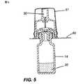
より詳細な図面及びその中の参照符号を参照して、参照符号10によって概略的に示され、参照符号12によって概略的に示される小瓶と共に使用するのに適した移送システムが説明される。 With reference to the more detailed drawings and reference numerals therein, a transfer system is described that is schematically indicated by
小瓶12は、キャップ18の上部を覆っている隔壁16でシールされたネックを備えた本体14を有する。薬剤20は、本体14内に収容される。薬剤は、代表的には、乾燥した成分であるが、流体もまた利用されることができる。 The
移送システム10は、外側ハウジング24と、円筒状の側壁26とを有する。円筒状の側壁26には、その底部の近くに突出部28が設けられている。その上端部には、ルアー接続部30が設けられている。内壁32は、当然に中空である針34を装着しており、この針は、穿孔端部36を有する。既に述べられたように、針34は、注射針であることができる。 The
可動部材40が、外側ハウジング24の内側に装着される。可動部材40は、針34の通路を与えるためにその中で中心に位置された開口44を備えた上壁42を有する。第1の脚46及び第2の脚48が、上壁42から下向きに延びている。第1の脚46は、その底部に、外向きに延びているフランジ50を有し、第2の脚48もまた、外向きに延びているフランジ52を有する。 A
カバー56は、移送システム10を収容するように設けられる。カバー56は、移送システム10を所定の位置に保持するために突出部28と係合するように構成された側壁57を有する。側壁57には、その底部に、外向きに延びているフランジ60が設けられている。フランジ60は、ハーメチックシールされたパッケージを与えるように、剥離可能なシールストリップ62を受けるように設計されている。
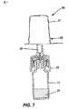
本発明の移送システムは、好ましくは、注射器本体66と、これに装着されるプランジャ68とを有する注射器と共に利用される。プランジャロッド70は、プランジャ68と螺合可能に係合するように設計されている。注射器本体66は、使用者の手で適切に把持されるように、戻り止め72を有する。注射器本体66は、その前端部にルアーコネクタ74を有する。代表的には、注射器本体66は、賦形剤76で充填されるが、他の所望の流体が利用されてもよい。 The transfer system of the present invention is preferably utilized with a syringe having a
図8並びに図9に示されるように、プランジャロッド70は、プランジャ68に接続されて、賦形剤76が、図10に示されるような小瓶本体14に追い出される。そして、薬剤及び賦形剤が混合されることができ、アセンブリが、図11に示されるように逆さにされる。そして、混合物80が、注射器本体66に吸い戻される。さらに、針アセンブリがルアーコネクタ74に接続されると、混合物80の注射の準備が整う。 As shown in FIGS. 8 and 9, the
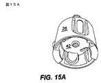
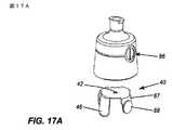
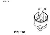
図17Aないし図17Hの実施の形態では、外側ハウジング24には、側壁26に1対の開口86が設けられている。また、この実施の形態では、さらなる1対の脚87が設けられ、これら脚が、それぞれ、その外面に形成されたボタン88を有する。この実施の形態では、可動部材40が上向きに動くと、ボタン88が開口86とそれぞれ係合する。 In the embodiment of FIGS. 17A-17H, the outer housing 24 is provided with a pair of
壁26の内面には、その中に形成された溝92を有するリブ90が設けられている。従って、小瓶12が引き出されるのにしたがって圧力がこれらボタン88に加えられると、上壁42が溝92と係合するまで可動部材40が下向きに動く。これにより、さらなる使用のために所定の位置で可動部材40が保持される。
図18ないし図19Dの実施の形態では、上壁42には、突出部96とロック用ラッチ98とが設けられていることが言及される。内部には、リブ100と、斜めの側壁部分102とが設けられている。この構成では、可動部材94の上向きの動きの際に、突出部96が、可動部材40を回動させるために斜めの側壁102と係合する。引き出す際には、ロック用ラッチ98が、移送部材のさらなる使用を防ぐようにリブ100と係合する。 In the embodiment of FIGS. 18-19D, it is noted that the
Claims (8)
Translated fromJapanese前記ハウジング(24)内に装着され、その底端部に位置された穿孔先端部(36)を有し、その中に形成された内部通路を有する穿孔部材(34)と、
前記上部の外側に位置されたコネクタ(30)と、
前記ハウジング(24)内に装着される可動部材(40)とを具備し、
前記可動部材(40)は、前記可動部材(40)が前記穿孔先端部(36)にアクセスするのを防ぐ第1の位置と、前記小瓶が前記ハウジング中に挿入されたときに前記穿孔先端部にアクセスするのを可能にする第2の位置とを移動可能である移送装置。A housing (24) having a top, a side wall (26), and an open bottom allowing insertion of the vial (12) therein;
A piercing member (34) mounted in the housing (24) and having a piercing tip (36) positioned at the bottom end thereof and having an internal passage formed therein;
A connector (30) located outside the top;
A movable member (40) mounted in the housing (24),
The movable member (40) includes a first position that prevents the movable member (40) from accessing the piercing tip (36) and the piercing tip when the vial is inserted into the housing. A transfer device movable between a second position allowing access to the device.
前記可動部材は、前記小瓶の取り外しの際に第3のロック位置に戻り、前記第3のロック位置では、さらなる小瓶が前記ハウジングに挿入されることができないようになっている請求項1の移送装置。The movable member (40) and the housing (24) rotate the movable member (40) when the movable member (40) moves upward when the small bottle (12) is inserted,
2. The transfer of claim 1, wherein the movable member returns to a third locked position upon removal of the vial, wherein no further vials can be inserted into the housing in the third locked position. apparatus.
前記ハウジングは、その中に形成された凹部を有し、
前記可動部材が前記第2の位置にあるとき、前記脚が前記凹部に係合し、
前記可動部材は、前記小瓶の取り外しの際に、前記凹部から前記脚を解放するように、前記脚への圧力によって前記第1の位置に復元可能である請求項1の移送装置。The movable member has at least one leg (46);
The housing has a recess formed therein;
When the movable member is in the second position, the leg engages the recess;
The transfer device according to claim 1, wherein the movable member can be restored to the first position by pressure on the leg so as to release the leg from the recess when the vial is removed.
Applications Claiming Priority (5)
| Application Number | Priority Date | Filing Date | Title |
|---|---|---|---|
| CA2733446ACA2733446A1 (en) | 2011-03-04 | 2011-03-04 | Easy linking device with retractable protector |
| CA2,733,446 | 2011-03-04 | ||
| CA2,746,031 | 2011-07-06 | ||
| CA2746031ACA2746031A1 (en) | 2011-07-06 | 2011-07-06 | Easy linking device with retractable protector |
| PCT/CA2012/000190WO2012119225A1 (en) | 2011-03-04 | 2012-03-05 | Easy linking transfer system |
Related Child Applications (1)
| Application Number | Title | Priority Date | Filing Date |
|---|---|---|---|
| JP2017062340ADivisionJP6502412B2 (en) | 2011-03-04 | 2017-03-28 | Easy to connect transport system |
Publications (1)
| Publication Number | Publication Date |
|---|---|
| JP2014511249Atrue JP2014511249A (en) | 2014-05-15 |
Family
ID=46797353
Family Applications (3)
| Application Number | Title | Priority Date | Filing Date |
|---|---|---|---|
| JP2013556940APendingJP2014511249A (en) | 2011-03-04 | 2012-03-05 | Easy transfer system |
| JP2017062340AActiveJP6502412B2 (en) | 2011-03-04 | 2017-03-28 | Easy to connect transport system |
| JP2018234525AActiveJP6676740B2 (en) | 2011-03-04 | 2018-12-14 | Easy connection system |
Family Applications After (2)
| Application Number | Title | Priority Date | Filing Date |
|---|---|---|---|
| JP2017062340AActiveJP6502412B2 (en) | 2011-03-04 | 2017-03-28 | Easy to connect transport system |
| JP2018234525AActiveJP6676740B2 (en) | 2011-03-04 | 2018-12-14 | Easy connection system |
Country Status (8)
| Country | Link |
|---|---|
| US (1) | US9381135B2 (en) |
| EP (1) | EP2680807B1 (en) |
| JP (3) | JP2014511249A (en) |
| CN (1) | CN103501751B (en) |
| AU (1) | AU2012225163B2 (en) |
| CA (1) | CA2827993C (en) |
| ES (1) | ES2593266T3 (en) |
| WO (1) | WO2012119225A1 (en) |
Cited By (2)
| Publication number | Priority date | Publication date | Assignee | Title |
|---|---|---|---|---|
| JP2019528978A (en)* | 2016-09-30 | 2019-10-17 | アイシーユー・メディカル・インコーポレーテッド | Pressure regulating vial access device and method |
| US12377022B2 (en) | 2014-06-20 | 2025-08-05 | Icu Medical, Inc. | Pressure-regulating vial adaptors |
Families Citing this family (42)
| Publication number | Priority date | Publication date | Assignee | Title |
|---|---|---|---|---|
| US7547300B2 (en) | 2006-04-12 | 2009-06-16 | Icu Medical, Inc. | Vial adaptor for regulating pressure |
| WO2010022095A1 (en) | 2008-08-20 | 2010-02-25 | Icu Medical, Inc. | Anti-reflux vial adaptors |
| ES3004613T3 (en) | 2009-07-29 | 2025-03-12 | Icu Medical Inc | Fluid transfer devices |
| JP2014511249A (en)* | 2011-03-04 | 2014-05-15 | デュオジェクト・メディカル・システムズ・インコーポレイテッド | Easy transfer system |
| CA3176437A1 (en) | 2011-08-18 | 2013-02-21 | Icu Medical, Inc. | Pressure-regulating vial adaptors |
| KR102145639B1 (en) | 2011-12-22 | 2020-08-19 | 아이씨유 메디칼 인코퍼레이티드 | Fluid transfer devices and methods of use |
| DK2802377T3 (en) | 2012-01-13 | 2017-03-20 | Icu Medical Inc | Pressure regulating bottle adapter and method |
| AU2013204180B2 (en) | 2012-03-22 | 2016-07-21 | Icu Medical, Inc. | Pressure-regulating vial adaptors |
| ES2634011T3 (en)* | 2012-05-21 | 2017-09-26 | Carmel Pharma Ab | Protective cap |
| ES2739291T3 (en) | 2013-01-23 | 2020-01-30 | Icu Medical Inc | Pressure regulation vial adapters |
| US9089475B2 (en) | 2013-01-23 | 2015-07-28 | Icu Medical, Inc. | Pressure-regulating vial adaptors |
| EP2759285A1 (en)* | 2013-01-28 | 2014-07-30 | Becton Dickinson France | Adaptor for coupling with a medical container |
| US9597260B2 (en) | 2013-03-15 | 2017-03-21 | Becton Dickinson and Company Ltd. | System for closed transfer of fluids |
| US9414990B2 (en) | 2013-03-15 | 2016-08-16 | Becton Dickinson and Company Ltd. | Seal system for cannula |
| CA3179530A1 (en) | 2013-07-19 | 2015-01-22 | Icu Medical, Inc. | Pressure-regulating fluid transfer systems and methods |
| EP3065694B1 (en) | 2013-11-06 | 2020-04-29 | Becton Dickinson and Company Limited | System for closed transfer of fluids having connector |
| ES2780857T3 (en) | 2013-11-06 | 2020-08-27 | Becton Dickinson & Co Ltd | Connection device for a medical device |
| CA2929476C (en) | 2013-11-06 | 2019-01-22 | Becton Dickinson and Company Limited | System for closed transfer of fluids with a locking member |
| ES2780856T3 (en) | 2013-11-06 | 2020-08-27 | Becton Dickinson & Co Ltd | Medical connector having locking coupling |
| ES2805051T3 (en) | 2013-11-25 | 2021-02-10 | Icu Medical Inc | Procedures and system for filling I.V. bags with therapeutic liquid |
| CN106232082B (en) | 2014-04-16 | 2019-03-12 | 贝克顿迪金森有限公司 | Fluid delivery device with axially and rotatably movable parts |
| BR112016024680B8 (en)* | 2014-04-21 | 2021-11-09 | Becton Dickinson & Co Ltd | Syringe adapter |
| EP3134057B1 (en) | 2014-04-21 | 2018-06-27 | Becton Dickinson and Company Limited | Syringe adapter with compound motion disengagement |
| AU2015249915B2 (en) | 2014-04-21 | 2017-11-30 | Becton Dickinson and Company Limited | System for closed transfer of fluids |
| EP3134058B1 (en) | 2014-04-21 | 2020-03-18 | Becton Dickinson and Company Limited | Fluid transfer device and packaging therefor |
| ES2792512T3 (en) | 2014-04-21 | 2020-11-11 | Becton Dickinson & Co Ltd | Fluid transfer device and packaging for it |
| EP3398583A1 (en) | 2014-04-21 | 2018-11-07 | Becton Dickinson and Company Limited | System with adapter for closed transfer of fluids |
| CN110353993B (en) | 2014-04-21 | 2022-04-12 | 贝克顿迪金森有限公司 | Bottle stabilizer base with attachable bottle adapter |
| EP4091597A1 (en) | 2014-04-21 | 2022-11-23 | Becton Dickinson and Company Limited | Syringe adapter with disconnection feedback mechanism |
| DE102015201288B4 (en) | 2015-01-26 | 2017-01-05 | Bayer Pharma AG | Hollow-needle assembly |
| DE102015201275A1 (en) | 2015-01-26 | 2016-07-28 | Bayer Pharma AG | Device for transferring a liquid between a storage container and at least one further use container |
| EP4534065A3 (en) | 2015-12-04 | 2025-06-04 | ICU Medical, Inc. | Systems methods and components for transferring medical fluids |
| IL243108B (en) | 2015-12-22 | 2018-08-30 | Kriheli Marino | Connector section |
| EP3397231B1 (en) | 2016-01-29 | 2022-03-02 | ICU Medical, Inc. | Pressure-regulating vial adaptors |
| DE102016110569B3 (en)* | 2016-06-08 | 2017-10-26 | Sfm Medical Devices Gmbh | adapter |
| USD851745S1 (en) | 2016-07-19 | 2019-06-18 | Icu Medical, Inc. | Medical fluid transfer system |
| EP3487468B1 (en) | 2016-07-25 | 2025-10-01 | ICU Medical, Inc. | Systems and components for trapping air bubbles in medical fluid transfer modules and systems |
| AU2018210833B2 (en)* | 2017-01-17 | 2023-05-04 | Becton Dickinson and Company Limited | Syringe adapter |
| EP4374891A3 (en)* | 2017-10-16 | 2024-08-28 | Enable Injections, Inc. | Pressurized gas powered liquid transfer device and system |
| US11590057B2 (en) | 2020-04-03 | 2023-02-28 | Icu Medical, Inc. | Systems, methods, and components for transferring medical fluids |
| JP2023538204A (en)* | 2020-06-25 | 2023-09-07 | バード・ペリフェラル・バスキュラー・インコーポレーテッド | Vial geometry for optimal mixing |
| JP2024529125A (en)* | 2021-08-12 | 2024-08-01 | ベクトン・ディキンソン・アンド・カンパニー | Syringe adapter with needle hub |
Citations (1)
| Publication number | Priority date | Publication date | Assignee | Title |
|---|---|---|---|---|
| JPH0686738U (en)* | 1992-06-16 | 1994-12-20 | 森下ルセル株式会社 | Medical container |
Family Cites Families (68)
| Publication number | Priority date | Publication date | Assignee | Title |
|---|---|---|---|---|
| US3047178A (en)* | 1958-06-24 | 1962-07-31 | Baxter Laboratories Inc | Closure system |
| SE434700B (en)* | 1983-05-20 | 1984-08-13 | Bengt Gustavsson | DEVICE FOR AIRED TRANSFER OF SUBSTANCE FROM A KERLE TO ANOTHER |
| WO1984004673A1 (en)* | 1983-05-20 | 1984-12-06 | Bengt Gustavsson | A device for transferring a substance |
| CA1335167C (en)* | 1988-01-25 | 1995-04-11 | Steven C. Jepson | Pre-slit injection site and associated cannula |
| JPH021277A (en)* | 1988-03-31 | 1990-01-05 | Fujisawa Pharmaceut Co Ltd | infusion container |
| US5171214A (en)* | 1990-12-26 | 1992-12-15 | Abbott Laboratories | Drug storage and delivery system |
| JPH06239352A (en)* | 1993-02-05 | 1994-08-30 | Nissho Corp | Solution injection set |
| US5429614A (en)* | 1993-06-30 | 1995-07-04 | Baxter International Inc. | Drug delivery system |
| RU2141306C1 (en)* | 1993-09-07 | 1999-11-20 | Дебиотек С.А. | Syringe device for mixing of two components |
| US5526853A (en)* | 1994-08-17 | 1996-06-18 | Mcgaw, Inc. | Pressure-activated medication transfer system |
| FR2726768A1 (en)* | 1994-11-14 | 1996-05-15 | Debiotech Sa | SYRINGE DEVICE ATTACHABLE TO A VIAL |
| US5647845A (en)* | 1995-02-01 | 1997-07-15 | Habley Medical Technology Corporation | Generic intravenous infusion system |
| IL114960A0 (en)* | 1995-03-20 | 1995-12-08 | Medimop Medical Projects Ltd | Flow control device |
| DK0928182T3 (en)* | 1996-01-11 | 2002-08-26 | Duoject Inc | Delivery system for medicines packed in pharmaceutical bottles |
| US5989237A (en)* | 1997-12-04 | 1999-11-23 | Baxter International Inc. | Sliding reconstitution device with seal |
| US6378714B1 (en)* | 1998-04-20 | 2002-04-30 | Becton Dickinson And Company | Transferset for vials and other medical containers |
| US6209738B1 (en)* | 1998-04-20 | 2001-04-03 | Becton, Dickinson And Company | Transfer set for vials and medical containers |
| US6022339A (en)* | 1998-09-15 | 2000-02-08 | Baxter International Inc. | Sliding reconstitution device for a diluent container |
| CA2345439C (en)* | 1998-10-29 | 2005-08-09 | Minimed, Inc. | Compact pump drive system |
| FR2789369B1 (en)* | 1999-02-10 | 2001-04-27 | Biodome | CONNECTION DEVICE BETWEEN A CONTAINER AND A CONTAINER AND READY-TO-USE ASSEMBLY COMPRISING SUCH A DEVICE |
| FR2790948B1 (en)* | 1999-03-18 | 2001-06-22 | Sedat | DEVICE FOR BIDIRECTIONAL TRANSFER OF A LIQUID BETWEEN A BOTTLE AND A CAPSULE |
| US7470258B2 (en)* | 2001-03-13 | 2008-12-30 | Mdc Investment Holdings, Inc. | Pre-filled safety vial injector |
| US6796967B2 (en)* | 2001-10-22 | 2004-09-28 | Nps Pharmaceuticals, Inc. | Injection needle assembly |
| US6875205B2 (en)* | 2002-02-08 | 2005-04-05 | Alaris Medical Systems, Inc. | Vial adapter having a needle-free valve for use with vial closures of different sizes |
| NZ538754A (en)* | 2002-09-03 | 2010-04-30 | Medical Instill Tech Inc | Sealed vial with a reseable stopper and methods of making and filling same |
| WO2004041148A1 (en)* | 2002-11-08 | 2004-05-21 | Duoject Medical Systems Inc. | Pharmaceutical delivery systems and methods for using same |
| US7678333B2 (en)* | 2003-01-22 | 2010-03-16 | Duoject Medical Systems Inc. | Fluid transfer assembly for pharmaceutical delivery system and method for using same |
| FR2856660A1 (en)* | 2003-06-30 | 2004-12-31 | Biodome | CONNECTION DEVICE BETWEEN A CONTAINER AND A CONTAINER AND READY-TO-USE ASSEMBLY COMPRISING SUCH A DEVICE |
| IN2014MN00187A (en)* | 2003-10-30 | 2015-08-21 | Teva Medical Ltd | |
| US7530546B2 (en)* | 2004-01-13 | 2009-05-12 | Rymed Technologies, Inc. | Swabbable needle-free injection port valve system with zero fluid displacement |
| IL161660A0 (en)* | 2004-04-29 | 2004-09-27 | Medimop Medical Projects Ltd | Liquid drug delivery device |
| US20060184103A1 (en)* | 2005-02-17 | 2006-08-17 | West Pharmaceutical Services, Inc. | Syringe safety device |
| US7648491B2 (en)* | 2005-05-13 | 2010-01-19 | Bob Rogers | Medical substance transfer system |
| GB0510057D0 (en)* | 2005-05-17 | 2005-06-22 | Glaxosmithkline Biolog Sa | Novel device |
| WO2007015233A1 (en)* | 2005-08-01 | 2007-02-08 | Medimop Medical Projects Ltd | Liquid drug delivery system |
| PL1971531T3 (en)* | 2005-11-30 | 2010-01-29 | Biocorp Rech Et Developpement | Plug device for a container and container provided with one such device |
| EP1993503A1 (en)* | 2006-03-06 | 2008-11-26 | Novo Nordisk A/S | A drug mixing device |
| WO2007101772A1 (en)* | 2006-03-07 | 2007-09-13 | Novo Nordisk A/S | A drug mixing device |
| US7547300B2 (en)* | 2006-04-12 | 2009-06-16 | Icu Medical, Inc. | Vial adaptor for regulating pressure |
| CA2652206C (en)* | 2006-05-25 | 2014-02-11 | Bayer Healthcare Llc | Reconstitution device |
| US8211082B2 (en)* | 2006-06-19 | 2012-07-03 | Nipro Corporation | Drug solution preparing kit |
| CA2564061A1 (en)* | 2006-10-16 | 2008-04-16 | Duoject Medical Systems Inc. | Reconstitution system for mixing the contents of a vial containing a first substance with a second substance stored in a cartridge |
| US8167863B2 (en)* | 2006-10-16 | 2012-05-01 | Carefusion 303, Inc. | Vented vial adapter with filter for aerosol retention |
| FR2911493B1 (en)* | 2007-01-24 | 2009-03-13 | Technoflex Sa | METHOD AND SET FOR TRANSFERRING A FLUID BETWEEN TWO CONTAINERS. |
| US20080262466A1 (en)* | 2007-04-19 | 2008-10-23 | Steve Smith | Storage container |
| KR101507841B1 (en)* | 2007-04-23 | 2015-04-07 | 플라스트메드 리미티드 | Method and apparatus for contamination-free transfer of a hazardous drug |
| US20080306439A1 (en)* | 2007-06-08 | 2008-12-11 | Nelson M Bud | Devices for mixing and applying a fluid composition |
| US8287513B2 (en)* | 2007-09-11 | 2012-10-16 | Carmel Pharma Ab | Piercing member protection device |
| AU2009203557B2 (en)* | 2008-01-09 | 2014-02-20 | Novartis Ag | Unitary withdrawal spike unit suitable for factory fitting |
| FR2928539B1 (en)* | 2008-03-12 | 2012-02-24 | Vygon | INTERFACING DEVICE FOR PERFORATING BOTTLES FOR THE PREPARATION OF PERFUME FLUIDS |
| EP2391329B1 (en)* | 2009-01-30 | 2017-06-28 | Biocompatibles UK Limited | Method for increasing the leakage resistance in a closed, pressurized system comprising a septum-sealed container |
| US8864725B2 (en)* | 2009-03-17 | 2014-10-21 | Baxter Corporation Englewood | Hazardous drug handling system, apparatus and method |
| US8277424B2 (en)* | 2009-07-17 | 2012-10-02 | Pan Hsiu-Feng | Needle-less syringe adapter |
| US9662271B2 (en)* | 2009-10-23 | 2017-05-30 | Amgen Inc. | Vial adapter and system |
| EP2493546A4 (en)* | 2009-10-30 | 2014-08-13 | Revance Therapeutics Inc | DEVICE AND METHOD FOR THE TOPICAL APPLICATION OF THERAPEUTIC OR COSMETIC COMPOSITIONS |
| IL202070A0 (en)* | 2009-11-12 | 2010-06-16 | Medimop Medical Projects Ltd | Inline liquid drug medical device |
| US9492353B2 (en)* | 2009-11-20 | 2016-11-15 | Carmel Pharma Ab | Medical device connector |
| US9205248B2 (en)* | 2010-02-24 | 2015-12-08 | Becton, Dickinson And Company | Safety Drug delivery connectors |
| CN103167857B (en)* | 2010-06-30 | 2014-12-10 | 泰尔茂株式会社 | Connector and connector assembly |
| JP2014511249A (en)* | 2011-03-04 | 2014-05-15 | デュオジェクト・メディカル・システムズ・インコーポレイテッド | Easy transfer system |
| US9480623B2 (en)* | 2011-10-14 | 2016-11-01 | Novo Nordisk Healthcare Ag | Pre-assembled fluid transfer arrangement |
| EP2787951B1 (en)* | 2011-12-08 | 2016-03-16 | Novo Nordisk Health Care AG | Medical device having integrated sequence control |
| JP5510986B2 (en)* | 2012-04-02 | 2014-06-04 | 株式会社メディカルクリエーション | Drug transfer device |
| IL221634A0 (en)* | 2012-08-26 | 2012-12-31 | Medimop Medical Projects Ltd | Universal drug vial adapter |
| US9724269B2 (en)* | 2012-11-30 | 2017-08-08 | Becton Dickinson and Company Ltd. | Connector for fluid communication |
| US9597260B2 (en)* | 2013-03-15 | 2017-03-21 | Becton Dickinson and Company Ltd. | System for closed transfer of fluids |
| JP6446438B2 (en)* | 2013-09-23 | 2018-12-26 | ベクトン ディキンソン アンド カンパニー リミテッド | Puncture member for container access device |
| EP3065694B1 (en)* | 2013-11-06 | 2020-04-29 | Becton Dickinson and Company Limited | System for closed transfer of fluids having connector |
- 2012
- 2012-03-05JPJP2013556940Apatent/JP2014511249A/enactivePending
- 2012-03-05EPEP12754579.6Apatent/EP2680807B1/enactiveActive
- 2012-03-05ESES12754579.6Tpatent/ES2593266T3/enactiveActive
- 2012-03-05CNCN201280020984.9Apatent/CN103501751B/enactiveActive
- 2012-03-05AUAU2012225163Apatent/AU2012225163B2/enactiveActive
- 2012-03-05WOPCT/CA2012/000190patent/WO2012119225A1/enactiveApplication Filing
- 2012-03-05USUS13/261,729patent/US9381135B2/enactiveActive
- 2012-03-05CACA2827993Apatent/CA2827993C/enactiveActive
- 2017
- 2017-03-28JPJP2017062340Apatent/JP6502412B2/enactiveActive
- 2018
- 2018-12-14JPJP2018234525Apatent/JP6676740B2/enactiveActive
Patent Citations (1)
| Publication number | Priority date | Publication date | Assignee | Title |
|---|---|---|---|---|
| JPH0686738U (en)* | 1992-06-16 | 1994-12-20 | 森下ルセル株式会社 | Medical container |
Cited By (8)
| Publication number | Priority date | Publication date | Assignee | Title |
|---|---|---|---|---|
| US12377022B2 (en) | 2014-06-20 | 2025-08-05 | Icu Medical, Inc. | Pressure-regulating vial adaptors |
| JP2019528978A (en)* | 2016-09-30 | 2019-10-17 | アイシーユー・メディカル・インコーポレーテッド | Pressure regulating vial access device and method |
| JP7063891B2 (en) | 2016-09-30 | 2022-05-09 | アイシーユー・メディカル・インコーポレーテッド | Vial adapter |
| JP2022097539A (en)* | 2016-09-30 | 2022-06-30 | アイシーユー・メディカル・インコーポレーテッド | adapter |
| US11744775B2 (en) | 2016-09-30 | 2023-09-05 | Icu Medical, Inc. | Pressure-regulating vial access devices and methods |
| JP7384954B2 (en) | 2016-09-30 | 2023-11-21 | アイシーユー・メディカル・インコーポレーテッド | adapter |
| JP2023184692A (en)* | 2016-09-30 | 2023-12-28 | アイシーユー・メディカル・インコーポレーテッド | Pressure regulating vial access device and method thereof |
| JP7556120B2 (en) | 2016-09-30 | 2024-09-25 | アイシーユー・メディカル・インコーポレーテッド | Pressure-regulated vial access device and method thereof |
Also Published As
| Publication number | Publication date |
|---|---|
| CA2827993C (en) | 2018-04-17 |
| CN103501751A (en) | 2014-01-08 |
| JP2019072508A (en) | 2019-05-16 |
| JP6676740B2 (en) | 2020-04-08 |
| ES2593266T3 (en) | 2016-12-07 |
| JP6502412B2 (en) | 2019-04-17 |
| US9381135B2 (en) | 2016-07-05 |
| EP2680807A4 (en) | 2014-08-27 |
| JP2017140419A (en) | 2017-08-17 |
| CA2827993A1 (en) | 2012-09-13 |
| AU2012225163B2 (en) | 2016-05-12 |
| WO2012119225A1 (en) | 2012-09-13 |
| US20140000738A1 (en) | 2014-01-02 |
| EP2680807B1 (en) | 2016-08-10 |
| EP2680807A1 (en) | 2014-01-08 |
| AU2012225163A1 (en) | 2013-09-12 |
| CN103501751B (en) | 2016-11-23 |
Similar Documents
| Publication | Publication Date | Title |
|---|---|---|
| JP6676740B2 (en) | Easy connection system | |
| US8480645B1 (en) | Multi-dose device for insertion into a vial and method of using the same | |
| JP6271549B2 (en) | Reconstruction device | |
| US8869635B2 (en) | Easy-link device for fluid transfer | |
| JP2001514029A (en) | Mixing flask for contacting two compounds separated from each other before collection and injection by syringe | |
| US9956142B2 (en) | Reconstitution device with tip cap | |
| US10736818B2 (en) | Reconstitution device with tip cap | |
| CN113573682B (en) | Fluid transfer device | |
| WO2020037393A1 (en) | Easy linking transfer system with venting | |
| CA2746031A1 (en) | Easy linking device with retractable protector | |
| CA2733446A1 (en) | Easy linking device with retractable protector |
Legal Events
| Date | Code | Title | Description |
|---|---|---|---|
| A621 | Written request for application examination | Free format text:JAPANESE INTERMEDIATE CODE: A621 Effective date:20150223 | |
| A131 | Notification of reasons for refusal | Free format text:JAPANESE INTERMEDIATE CODE: A131 Effective date:20151208 | |
| A601 | Written request for extension of time | Free format text:JAPANESE INTERMEDIATE CODE: A601 Effective date:20160304 | |
| A521 | Request for written amendment filed | Free format text:JAPANESE INTERMEDIATE CODE: A523 Effective date:20160608 | |
| A02 | Decision of refusal | Free format text:JAPANESE INTERMEDIATE CODE: A02 Effective date:20161129 |