JP2014511209A - Reading and adjusting tool for hydrocephalus shunt valve - Google Patents
Reading and adjusting tool for hydrocephalus shunt valveDownload PDFInfo
- Publication number
- JP2014511209A JP2014511209AJP2013552005AJP2013552005AJP2014511209AJP 2014511209 AJP2014511209 AJP 2014511209AJP 2013552005 AJP2013552005 AJP 2013552005AJP 2013552005 AJP2013552005 AJP 2013552005AJP 2014511209 AJP2014511209 AJP 2014511209A
- Authority
- JP
- Japan
- Prior art keywords
- valve
- reading
- signal
- coil
- adjusting tool
- Prior art date
- Legal status (The legal status is an assumption and is not a legal conclusion. Google has not performed a legal analysis and makes no representation as to the accuracy of the status listed.)
- Granted
Links
- 208000003906hydrocephalusDiseases0.000titledescription8
- 230000005284excitationEffects0.000claimsabstractdescription41
- 230000005672electromagnetic fieldEffects0.000claimsabstractdescription11
- 230000001105regulatory effectEffects0.000claimsdescription3
- 230000004044responseEffects0.000claimsdescription3
- 210000001175cerebrospinal fluidAnatomy0.000description16
- 239000012530fluidSubstances0.000description8
- 230000007246mechanismEffects0.000description8
- 239000003990capacitorSubstances0.000description7
- 230000008859changeEffects0.000description7
- 230000003750conditioning effectEffects0.000description7
- 238000000034methodMethods0.000description7
- 238000002595magnetic resonance imagingMethods0.000description5
- ZLGYJAIAVPVCNF-UHFFFAOYSA-N1,2,4-trichloro-5-(3,5-dichlorophenyl)benzeneChemical compoundClC1=CC(Cl)=CC(C=2C(=CC(Cl)=C(Cl)C=2)Cl)=C1ZLGYJAIAVPVCNF-UHFFFAOYSA-N0.000description4
- 210000004556brainAnatomy0.000description4
- 238000010586diagramMethods0.000description4
- 230000004907fluxEffects0.000description4
- 210000000683abdominal cavityAnatomy0.000description3
- 230000008878couplingEffects0.000description3
- 238000010168coupling processMethods0.000description3
- 238000005859coupling reactionMethods0.000description3
- 230000006870functionEffects0.000description3
- 230000008901benefitEffects0.000description2
- 210000005013brain tissueAnatomy0.000description2
- 210000005166vasculatureAnatomy0.000description2
- 230000000007visual effectEffects0.000description2
- PIVBPZFQXKMHBD-UHFFFAOYSA-N1,2,3-trichloro-5-(2,5-dichlorophenyl)benzeneChemical compoundClC1=CC=C(Cl)C(C=2C=C(Cl)C(Cl)=C(Cl)C=2)=C1PIVBPZFQXKMHBD-UHFFFAOYSA-N0.000description1
- 206010008111Cerebral haemorrhageDiseases0.000description1
- 208000017667Chronic DiseaseDiseases0.000description1
- 238000010521absorption reactionMethods0.000description1
- 238000009825accumulationMethods0.000description1
- 230000032683agingEffects0.000description1
- 238000004873anchoringMethods0.000description1
- 230000009286beneficial effectEffects0.000description1
- 239000000560biocompatible materialSubstances0.000description1
- 239000003086colorantSubstances0.000description1
- 238000005336crackingMethods0.000description1
- 230000001627detrimental effectEffects0.000description1
- 230000002068genetic effectEffects0.000description1
- 238000002513implantationMethods0.000description1
- 208000014674injuryDiseases0.000description1
- 230000003993interactionEffects0.000description1
- 239000004973liquid crystal related substanceSubstances0.000description1
- 239000000696magnetic materialSubstances0.000description1
- 230000037361pathwayEffects0.000description1
- 230000008569processEffects0.000description1
- 230000008844regulatory mechanismEffects0.000description1
- 229910001285shape-memory alloyInorganic materials0.000description1
- 210000003625skullAnatomy0.000description1
- 230000008733traumaEffects0.000description1
- 230000002792vascularEffects0.000description1
Images


Classifications
- F—MECHANICAL ENGINEERING; LIGHTING; HEATING; WEAPONS; BLASTING
- F16—ENGINEERING ELEMENTS AND UNITS; GENERAL MEASURES FOR PRODUCING AND MAINTAINING EFFECTIVE FUNCTIONING OF MACHINES OR INSTALLATIONS; THERMAL INSULATION IN GENERAL
- F16K—VALVES; TAPS; COCKS; ACTUATING-FLOATS; DEVICES FOR VENTING OR AERATING
- F16K37/00—Special means in or on valves or other cut-off apparatus for indicating or recording operation thereof, or for enabling an alarm to be given
- F16K37/0025—Electrical or magnetic means
- F16K37/0041—Electrical or magnetic means for measuring valve parameters
- A—HUMAN NECESSITIES
- A61—MEDICAL OR VETERINARY SCIENCE; HYGIENE
- A61M—DEVICES FOR INTRODUCING MEDIA INTO, OR ONTO, THE BODY; DEVICES FOR TRANSDUCING BODY MEDIA OR FOR TAKING MEDIA FROM THE BODY; DEVICES FOR PRODUCING OR ENDING SLEEP OR STUPOR
- A61M27/00—Drainage appliance for wounds or the like, i.e. wound drains, implanted drains
- A61M27/002—Implant devices for drainage of body fluids from one part of the body to another
- A61M27/006—Cerebrospinal drainage; Accessories therefor, e.g. valves
- Y—GENERAL TAGGING OF NEW TECHNOLOGICAL DEVELOPMENTS; GENERAL TAGGING OF CROSS-SECTIONAL TECHNOLOGIES SPANNING OVER SEVERAL SECTIONS OF THE IPC; TECHNICAL SUBJECTS COVERED BY FORMER USPC CROSS-REFERENCE ART COLLECTIONS [XRACs] AND DIGESTS
- Y10—TECHNICAL SUBJECTS COVERED BY FORMER USPC
- Y10T—TECHNICAL SUBJECTS COVERED BY FORMER US CLASSIFICATION
- Y10T137/00—Fluid handling
- Y10T137/7722—Line condition change responsive valves
- Y10T137/7758—Pilot or servo controlled
- Y10T137/7761—Electrically actuated valve
- Y—GENERAL TAGGING OF NEW TECHNOLOGICAL DEVELOPMENTS; GENERAL TAGGING OF CROSS-SECTIONAL TECHNOLOGIES SPANNING OVER SEVERAL SECTIONS OF THE IPC; TECHNICAL SUBJECTS COVERED BY FORMER USPC CROSS-REFERENCE ART COLLECTIONS [XRACs] AND DIGESTS
- Y10—TECHNICAL SUBJECTS COVERED BY FORMER USPC
- Y10T—TECHNICAL SUBJECTS COVERED BY FORMER US CLASSIFICATION
- Y10T137/00—Fluid handling
- Y10T137/8158—With indicator, register, recorder, alarm or inspection means
- Y10T137/8225—Position or extent of motion indicator
- Y10T137/8242—Electrical
Landscapes
- Health & Medical Sciences (AREA)
- Engineering & Computer Science (AREA)
- Biomedical Technology (AREA)
- General Engineering & Computer Science (AREA)
- Hematology (AREA)
- Otolaryngology (AREA)
- Anesthesiology (AREA)
- Heart & Thoracic Surgery (AREA)
- Ophthalmology & Optometry (AREA)
- Life Sciences & Earth Sciences (AREA)
- Animal Behavior & Ethology (AREA)
- General Health & Medical Sciences (AREA)
- Public Health (AREA)
- Veterinary Medicine (AREA)
- Neurology (AREA)
- Mechanical Engineering (AREA)
- External Artificial Organs (AREA)
Abstract
Translated fromJapaneseDescription
Translated fromJapanese本開示は、一般に、外科的に埋め込まれる生理的シャントシステム、および関連する流量制御装置に関する。本開示は、より詳細には、脳室から外に流れる脳脊髄液(CSF)の流量を制御し、流体が脳室内に逆流するのを防止する一方向流量制御弁の可変の圧力または流量の設定を有するこうしたシャントシステムのための位置インジケータおよび調整工具に関する。 The present disclosure generally relates to surgically implanted physiological shunt systems and associated flow control devices. The present disclosure more particularly controls the flow rate of cerebrospinal fluid (CSF) flowing out of the ventricle and prevents the fluid from flowing back into the ventricle with a variable pressure or flow rate variable. It relates to a position indicator and adjustment tool for such a shunt system with settings.
典型的な大人は、全体で約120〜150立方センチメートル(cc)、脳室内に約40ccのCSFを有する。典型的な大人は、また、約400〜500cc/日のCSFを生成し、その全てが血流に常に再吸収される。 A typical adult has a total CSF of about 120-150 cubic centimeters (cc) and about 40 cc in the ventricle. A typical adult also produces about 400-500 cc / day of CSF, all of which is constantly reabsorbed into the bloodstream.
時に、脳が過剰なCSFを生成し、または、正常なCSFの経路、および/あるいは吸収部位が遮断され、水頭症として知られた状態になることがある。水頭症は、脳室または脳組織にCSFが過剰に蓄積された状態である。水頭症は、遺伝的状況、脳の出血外傷に起因して、または加齢によって生じる可能性がある。 Sometimes the brain produces excess CSF, or normal CSF pathways and / or absorption sites are blocked, leading to a condition known as hydrocephalus. Hydrocephalus is a condition in which CSF is excessively accumulated in the ventricle or brain tissue. Hydrocephalus can result from a genetic condition, cerebral hemorrhage trauma, or due to aging.
水頭症、または他の原因によるCSFの過剰な蓄積は、脳内の圧力増加として現れる。原因が何であれ、徐々に、このCSF圧力の増加によって脳組織に障害が生じる。CSF圧力の緩和が治療的に有益であることが判明している。この緩和は、通常、CSFを脳室から排出することによって行われる。 Excessive accumulation of CSF due to hydrocephalus or other causes manifests as increased pressure in the brain. Whatever the cause, gradually, this increase in CSF pressure causes damage to brain tissue. It has been found that relief of CSF pressure is therapeutically beneficial. This relaxation is usually done by draining CSF from the ventricle.
水頭症の患者は、通常、少なくとも幾らかの期間にわたり、過剰なCSFを連続的に排出して、脳内の正常なCSF圧力を維持する必要がある。脳室内に蓄積された過剰なCSFは、通常、シャントシステムを使用して脳から排出される。 Hydrocephalic patients usually need to continuously drain excess CSF over at least some period to maintain normal CSF pressure in the brain. Excess CSF accumulated in the ventricle is usually drained from the brain using a shunt system.
水頭症が慢性状態の場合、シャントシステムでは、通常、CSFを患者の腹腔、または患者の脈管系内に排出する。こうしたシャントシステムは、通常、脳室内に埋め込まれたカテーテルを有する。カテーテルは流体制御装置に連結され、流体制御装置は、患者の腹腔または患者の脈管系内に排出するカテーテルに連結される。流体制御装置の一例が、William J.Bertrand、およびDavid A.Watsonに発行された1997年6月10日の「Implantable Adjustable Fluid Flow Control Valve」という名称の米国特許第5,637,083号に示されているに示されており、その教示の全体が参照により本明細書に組み込まれる。流れ流体制御装置は、入口コネクタ、出口コネクタ、および入口コネクタと出口コネクタの間に位置付けられた弁を含む。弁は、弁を通る流体の流れを制御する機構を含む。幾つかの例では、機構は弁内に埋め込まれた磁石を含む。回転子を回転させ、または他の方法で回転子の位置を移動させることによって、機構の内部構成が変わる。機構の内部構成の変更によって、弁の様々な圧力、または流れ特性が生成される。弁の内部構成が変わると、弁の圧力または流れ特性が変わる。 When hydrocephalus is a chronic condition, the shunt system typically drains CSF into the patient's abdominal cavity or into the patient's vasculature. Such shunt systems typically have a catheter implanted in the ventricle. The catheter is coupled to a fluid control device, which is coupled to a catheter that drains into the patient's abdominal cavity or the patient's vasculature. An example of a fluid control device is William J. et al. Bertrand, and David A.M. US Pat. No. 5,637,083 entitled “Implantable Adjustable Flow Control Valve” issued June 10, 1997 to Watson, the entire teachings of which are hereby incorporated by reference. Incorporated herein. The flow fluid control device includes an inlet connector, an outlet connector, and a valve positioned between the inlet connector and the outlet connector. The valve includes a mechanism that controls the flow of fluid through the valve. In some examples, the mechanism includes a magnet embedded in the valve. By rotating the rotor or otherwise moving the position of the rotor, the internal configuration of the mechanism changes. Changes in the internal configuration of the mechanism create various pressure or flow characteristics of the valve. As the internal configuration of the valve changes, the pressure or flow characteristics of the valve change.
使用の際は、弁が患者の頭骨上の皮下に配置される。患者の脳室内に入るカテーテルは、入口コネクタに取り付けられる。患者の腹腔または脈管系に入るカテーテルは出口コネクタに取り付けられる。こうすると、入口コネクタから弁を通って出口コネクタに流れる方向が確立される。外部磁石を内部磁石に結合し、外部磁石を回転させることによって、機構の内部構成が変わり、シャントの内部に運動が生じ、弁を通る様々な圧力または流れ特性が生成される。 In use, the valve is placed subcutaneously on the patient's skull. A catheter that enters the patient's ventricle is attached to the inlet connector. A catheter that enters the patient's abdominal cavity or vascular system is attached to the outlet connector. This establishes the direction of flow from the inlet connector through the valve to the outlet connector. By coupling the external magnet to the internal magnet and rotating the external magnet, the internal configuration of the mechanism changes, creating movement within the shunt and generating various pressure or flow characteristics through the valve.
幾つかの異なる設定を有して、弁の様々な圧力、および/または流れ特性を得ることが望ましい。埋め込み後の流量調整可能な弁の1つの問題は、弁の設定の決定、かつ/または弁の設定の調整が難しいことである。弁の設定をより多く有すると、弁の設定の決定、かつ/または調整がさらに難しくなるだけである。幾つかの調整可能な弁では、X線像を使用して、弁の現在の状態、または調整後の状態が決定される。X線を必要とするため、弁設定の決定および調整に時間とコストがかかり、また、X線被曝の問題により、患者の最大の利益にならない。 It is desirable to have several different settings to obtain various pressure and / or flow characteristics of the valve. One problem with adjustable flow valves after implantation is that it is difficult to determine valve settings and / or adjust valve settings. Having more valve settings only makes it more difficult to determine and / or adjust the valve settings. In some adjustable valves, the x-ray image is used to determine the current state of the valve or the state after adjustment. Because X-rays are required, the determination and adjustment of valve settings is time consuming and costly, and the problems of X-ray exposure do not provide the greatest benefit for the patient.
流量調整可能な弁の他の問題は、磁気共鳴映像法(MRI)処置との適合性である。多くの流量調整可能な弁が、弁の設定の調整および/または決定に磁石を使用しているため、弁の磁気成分とMRI処置中に生成される与えられた磁界との相互作用により、その機能が破壊される恐れがある。具体的には、弁設定が無作為の望ましくない設定に変更される可能性がある。MRI処置後に弁設定が望ましい設定に戻されないと、この状況が、患者に非常に有害な可能性がある。したがって、MRI処置の終了後に、弁設定を望ましい設定に即座に再設定する必要がある。いずれにしても、水頭症の治療のための弁の改良は大きな恩恵をもたらすことができる。 Another problem with flow adjustable valves is compatibility with magnetic resonance imaging (MRI) procedures. Many flow-adjustable valves use magnets to adjust and / or determine valve settings so that interaction between the magnetic component of the valve and the applied magnetic field generated during the MRI procedure causes its Function may be destroyed. Specifically, the valve setting may be changed to a random undesirable setting. This situation can be very detrimental to the patient if the valve settings are not returned to the desired settings after the MRI procedure. Therefore, it is necessary to immediately reset the valve setting to the desired setting after completion of the MRI procedure. In any case, improved valves for the treatment of hydrocephalus can provide significant benefits.
本明細書で示す概念は、埋め込み可能な医療装置の圧力または流量の設定の決定および/または調整に関する。 The concepts presented herein relate to determining and / or adjusting pressure or flow settings for an implantable medical device.
一実施形態では、複数の圧力または流量の設定に調整可能な圧力または流量の設定を有する弁と共に使用する読取および調整工具を開示する。工具は、信号発生器、および信号発生器に結合された励振コイルを含む。信号発生器は、圧力または流量の設定を調整するための調整信号を発生するように構成された調整インターフェース、および、弁の圧力または流量の設定を読み取るための読取信号を発生する読取インターフェースを含む。少なくとも1つの励振コイルが信号発生器に接続され、調整信号および読取信号の1つに基づいて振動電磁界を生成するように構成される。 In one embodiment, a reading and adjusting tool for use with a valve having adjustable pressure or flow settings for multiple pressure or flow settings is disclosed. The tool includes a signal generator and an excitation coil coupled to the signal generator. The signal generator includes an adjustment interface configured to generate an adjustment signal for adjusting a pressure or flow setting, and a read interface for generating a read signal for reading the valve pressure or flow setting. . At least one excitation coil is connected to the signal generator and is configured to generate an oscillating electromagnetic field based on one of the adjustment signal and the read signal.
他の実施形態では、複数の圧力または流量の設定に調整可能な圧力または流量の設定を有する弁と共に使用する手持型の弁の読取および調整工具を開示する。工具は、信号発生器、および信号発生器に結合された励振コイルを含む。読取コイルは、励振コイルの第1の側部に位置付けられた第1のコイル部分、および励振コイルの第1の部分の反対側に位置付けられた第2のコイル部分を含む。工具は、さらに、読取コイルに結合された信号検出器を含む。信号発生器は、読取信号を弁に送るように構成され、読取コイルは、読取信号に基づく圧力または流量の設定の提示を受信するように構成される。 In another embodiment, a handheld valve reading and adjusting tool for use with a valve having adjustable pressure or flow settings for multiple pressure or flow settings is disclosed. The tool includes a signal generator and an excitation coil coupled to the signal generator. The read coil includes a first coil portion positioned on the first side of the excitation coil and a second coil portion positioned on the opposite side of the first portion of the excitation coil. The tool further includes a signal detector coupled to the reading coil. The signal generator is configured to send a read signal to the valve, and the read coil is configured to receive an indication of a pressure or flow rate setting based on the read signal.
図1は、埋め込み可能な流量制御装置12(たとえばシャント)、並びに、電子弁読取および調整工具14を含む、調整可能なシャントシステム10の概略ブロック図である。全般的に、装置12を患者の体内に埋め込んで、装置12の(弁設定としても知られる)圧力または流量の設定に基づき、患者の体内の流体(たとえば上記で論じたCSF)の流量を調整することができる。工具14は、装置12に近接するように位置付けられた場合に、装置12の圧力あるいは流量の設定を皮下で読み取り、かつ/または調整するように構成された手持型機構でもよい。具体的には、工具14は、装置12によって受けられる振動電磁界を生成することができる。以下で論じるように、磁界は、装置12が圧力あるいは流量の設定を調整し、かつ/または、圧力もしくは流量の設定を示すフィードバックを提供するようにさせることができる。 FIG. 1 is a schematic block diagram of an
装置12は、弁16、調整回路アセンブリ18、読取回路アセンブリ20、および、弁16を調整回路アセンブリ18と読取回路アセンブリ20に結合するコネクタアセンブリ22を含む。一実施形態では、調整回路アセンブリ18は、コネクタアセンブリ22の弁16に対する相対位置を変更して、弁16の圧力または流量の設定を変更させる調整機構を含む。さらに、コネクタアセンブリ22は、コネクタアセンブリ22と弁16の相対位置の関数として、読取回路アセンブリ20の共振周波数を変更する素子を含むことができる。一例の弁が、さらに、本明細書と同日付で出願された「Adjustment for Hydrocephalus Shunt Valve」という名称の同時係属の米国特許出願第13/015,174号に記載されており、その内容全体が参照により本明細書に組み込まれる。全般的に、流体は、(弁16が逆止め弁として動作する場合)弁16のクラッキング圧力を示す弁設定によって、弁16を通って入口コネクタ24から出口コネクタ26に流れることができる。弁16は、装置12を通る流体の圧力および/または流れ特性を変える幾つかの設定を規定する。調整回路アセンブリ18は、弁16にコネクタアセンブリ22によって結合されて、工具14からの信号(たとえば電磁界)に基づき、圧力または流量の設定を変える。読取回路20も弁16にコネクタアセンブリ22よって結合され、工具14からの信号(たとえば電磁界)に応答して、圧力または流量の設定を示す信号を工具14に提供するように構成される。装置12を生体適合性材料で形成して、患者の皮下に位置付けることができる。さらに、材料の磁気材料の使用を制限して、装置12の圧力または流量の設定がMRI処置中に変更されないようにすることができる。 The
工具14は、信号発生器32、コイルアセンブリ34、信号検出器36、およびユーザインターフェース38に電力を供給するように構成された電源30を含む。工具14の信号発生器32は、出力信号(たとえば電磁界)をコイルアセンブリ34によって装置12内の調整回路アセンブリ18および読取回路アセンブリ20に提供するように適合される。具体的には、信号発生器32はコイルアセンブリ34に結合され、調整回路アセンブリ18および読取回路アセンブリ20の共振周波数と一致する出力信号を送って、調整回路アセンブリ18および読取回路アセンブリ20に電流を誘導することができる。調整回路アセンブリ内に誘導された電流を使用して、弁16の圧力または流量の設定を変更する調整機構が駆動される。さらに、工具14によって感知される電流を使用して、生体内調整回路アセンブリ18とコイルアセンブリ34の結合が推定される。この結合の推定を使用して、設定する場合に、ユーザを弁に案内し、生体内調整回路アセンブリ18に送られる電力を制限することができる。一実施形態では、調整機構は、形状記憶合金で形成されたワイアであり、電流がワイアに誘導されると収縮し、圧力または流量の設定を変更させる。一実施形態では、調整回路アセンブリ18の共振周波数は約100kHzであるが、他の周波数を使用することもできる。 Tool 14 includes a
同様に、信号発生器32は、また、読取回路アセンブリ20の共振周波数と一致する出力信号(たとえば電磁界)を読取回路アセンブリ20に送るように適合される。しかし、読取回路アセンブリ20の共振周波数は、弁16の圧力または流量の設定の関数として変わる。その結果、信号発生器32は、(たとえば走査操作を行うことによって)複数の周波数の信号を伝送し、どの周波数が読取回路アセンブリ20の共振周波数かを決定するように構成される。具体的には、手持形器の信号の周波数が弁に十分近い場合、信号発生器32によって送られた信号が読取回路アセンブリ20中に電流を誘導し、磁界が生成され、その磁界を信号検出器36が感知することができる。信号検出器36によって検出された信号の強度に基づいて、工具14から装置までの距離を推定することができる。一実施形態では、読取回路アセンブリ20の共振周波数は(通常)約1MHzであり、信号発生器32によって発生することができる周波数の範囲内に調整可能である。共振周波数情報を使用して、弁16の圧力または流量の設定を、たとえば参照表を使用して、決定することができる。 Similarly, the
ユーザインターフェース38は、信号発生器32および信号検出器36の操作の可視指示を提供し、工具14への入力を可能にし、工具14の装置12への近接を示す可視指示を提供することができる。たとえば、ユーザインターフェース38は、圧力情報を表示するスクリーン、工具14の操作を変更する1つまたは複数のボタン、および/または1組のインジケータを含むことができる。一実施形態では、1組のインジケータは、検出器36によって検出された信号の強度を示すことができる。検出された信号が弱すぎる場合、ユーザは、工具14が許容可能な動作範囲内に入るまで工具14を装置12に近づけることができる。 The
図2は、弁12の圧力あるいは流量の設定を調整し、かつ/または読み取るように動作可能な工具14内の選択構成要素の概略ブロック図である。図2は、図1の信号発生器32、コイルアセンブリ34、および信号検出器36を示している。信号発生器32は、リレー54に動作可能に結合された調整インターフェース50および読取インターフェース52を含み、リレー54はコイルアセンブリ34に結合される。コイルアセンブリ34は、励振コイル56、および励振コイル56の両側に位置付けられた第1のコイル部分58aおよび第2のコイル部分58bを有する感知(または読取)コイル58を含む。一実施形態では、コイル部分58aおよび58bは励振コイル56から等しい間隔をおいて配置される。したがって、励振コイル56によって生成される電磁界からの磁束がコイル58内で取り消され、ゆえに、信号検出器36はコイル58内の信号を検出しない。換言すれば、読取回路アセンブリ20からの磁束の感知は、励振コイル56によって提供される信号とは無関係である。具体的には、コイル部分58aを通過する磁束はコイル部分58b中に生成される電圧に並列の電圧を生成し、感知コイル58内の励振コイル56からの信号が取り消される。励振コイル56からの信号が取り消されないと、校正プロセスが行われて、励振コイル56中に信号が発生されると、コイル58が信号を検出しない可能性がある。リレー54は、工具14が装置12の圧力あるいは流量の設定を調整するモード、または装置12の圧力もしくは流量の設定を読み取るモードにあるかどうかによって、信号を調整インターフェース50または読取インターフェース52から励振コイル56に送るように動作可能である。こうすると、リレー54は、コイル56に送られる出力信号として、調整インターフェース50からの調整信号および読取インターフェース52からの読取信号の1つを選択することができる。一代替実施形態では、調整インターフェース50からの信号を提供するコイル、および読取インターフェース52からの信号を提供するコイルの2つの励振コイルを使用することができる。この実施形態では、リレー54を省くことができる。 FIG. 2 is a schematic block diagram of selected components within the tool 14 operable to adjust and / or read the pressure or flow settings of the
調整インターフェース50は、調整駆動回路60、および1つまたは複数のコンデンサ62を含む。調整駆動回路60およびコンデンサ62は、図1の調整回路アセンブリ18の共振周波数と一致する信号を発生するように構成される。一実施形態では、調整駆動回路60は、1つまたは複数のコンデンサ62に電圧を加えるH橋として実施される。装置14が調整モードで動作する場合、リレー54はコンデンサ62から励振コイル56に電流を送る。励振コイル56は、調整駆動回路60およびコンデンサ62の動作に基づいて振動電磁界を生成し、振動電磁界が装置12によって受けられて、装置12の圧力または流量の設定が調整される。 The
読取インターフェース52は、読取駆動回路64、インダクタ66を含む。別法として、要望通りに、インダクタ66をコンデンサに代えることができる。一例では、読取駆動回路64は、幾つかの異なる周波数を走査して、読取回路アセンブリ20の特定の周波数と一致させるように構成された直接ディジタルサンプラとして実施される。読取駆動回路64はリレー54によってコイルアセンブリ34の励振コイル56に連結される。弁が励振コイルの範囲内に存在する場合に、読取回路アセンブリ20中に電流が誘導される。読取回路アセンブリ20中の電流が、次いで、感知コイル58によって感知される。具体的には、読取回路アセンブリ20中の電流によって生成された磁束がコイル58中に電流を生成する。検出器36はコイル58に結合されて(すなわち、読取回路アセンブリ20中に生成された電流から読取コイル58に誘導された電流を感知することによって)、読取回路アセンブリ20が共振する周波数を決定するようになされる。決定された周波数は、装置12の圧力または流量の設定を示すものである。この設定をたとえば、ユーザインターフェース38によって、工具14のユーザに送ることができる。 The
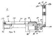
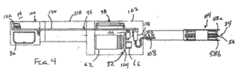
図3〜5は、工具14の一実施形態の概略図である。工具14は、本体部分102、および旋回アセンブリ108の周りで本体部分102に対して旋回可能なコイルアセンブリハウジング104を含むハウジング100(全般的に参照)を含む。コイルアセンブリハウジング104は、図3で示したように、本体部分102の長さに対して全般的に垂直の位置、および図4で示したように、全般的に水平の位置を含む複数の位置に位置付けることができる。別法として、他の実施形態では、コイルアセンブリハウジング104は、たとえばコードで係留することによって、ハウジング100に対して可動であり、またはハウジング100の周りで回転可能である。一実施形態では、旋回アセンブリ108は、複数の角度の中で選択される位置を可能にし、図3および4のコイルアセンブリハウジング104の位置を含む、摩擦ヒンジである。本体部分102は、ユーザが便利に把持するための細くなった中央部分110を含む。したがって、ユーザは、工具14を容易に位置付けることができ、具体的には、コイルアセンブリハウジング104を患者の体内に埋め込まれた装置12に近接するように位置付けることができる。 3-5 are schematic views of one embodiment of the tool 14. The tool 14 includes a housing 100 (see generally) that includes a
上記で論じた工具14の構成要素はハウジング100内に位置付けられる。電源30、信号発生器32、信号検出器36、およびユーザインターフェース38は、全て本体部分102内に位置付けられ、コイルアセンブリ34はコイルアセンブリハウジング104内に位置付けられる。電源30は、図で示した実施形態では、本体部分102内に位置付けられた主プリント回路板(PCB)120に電気的に結合された電池である。コネクタ122は、従来の120ボルトの交流(AC)出口など、ACからDCへの外部電源に接続可能である。コネクタ122を従来の出口に接続することによって、電池30を再充電することができる。信号発生器32は、コンデンサ62およびインダクタ66を主PCB120にコネクタ126によって接続する対応するプリント回路板(PCB)124を含む。図2で示したリレー54、調整駆動回路60、および読取駆動回路64が図3〜5に示されていないが、要望通りに、PCB120またはPCB124上に位置付けることができる。さらに、ユーザインターフェース38(全般的に参照)用の回路をPCB120上に位置付けることができ、本体部分102の頂部付近に位置付けて、ユーザが容易に見ることができるようにする。コイルアセンブリ34はPCB120に適したコネクタ128によって結合される。 The components of the tool 14 discussed above are positioned within the
工具14の動作は、ユーザインターフェース38によって制御され、その一例が図6に示されている。ユーザインターフェース38は、電源ボタン150、読取選択ボタン152、調整選択ボタン154、並びに、圧力または流量の設定ボタン156および158を含む。電源ボタン150は選択的に工具14の電源を入れたり切ったりする。読取選択ボタン152、および調整選択ボタン154は、それぞれ(装置12の圧力または流量の設定を読み取る)読取モード、および(装置12の圧力または流量の設定を調整する)調整モードに選択するように構成される。調整モードが選択された後、圧力または流量の設定ボタン156および158を押して、それぞれ装置12の圧力を上昇または低下させるように調整することができる。 The operation of the tool 14 is controlled by the
ユーザインターフェース38は、さらに、(本明細書で発光ダイオード(LED)として示されている)1組のインジケータ160、および(本明細書で液晶ディスプレイとして示されている)ディスプレイスクリーン162を含む。1組のインジケータ160は、ユーザに工具14と装置12の近接を示す提示を与えることができる。たとえば、全てのインジケータが点灯した場合、これは工具14が装置12に近接近して、工具14が装置12の圧力あるいは流量の設定を読み取り、かつ/または調整する動作可能な範囲内に存在することを示すことができる。インジケータ160が1つも点灯されない場合、または全てより少ない数のインジケータ160が点灯された場合、これはユーザに工具14を装置12により近接するように移動させることを示すことができる。様々な色のLEDなど、ユーザに提示を与える他の方法を使用することができる。スクリーン162を使用して、装置12から受信した圧力または流量の設定の情報を表示し、かつ/または行われる圧力または流量の設定の調整を示すことができる。 The
本開示を好ましい実施形態を参照して記載したが、当業者には理解されるように、本開示の精神および範囲から逸脱することなく、形態および詳細に変更を加えることができる。 Although the present disclosure has been described with reference to preferred embodiments, changes can be made in form and detail without departing from the spirit and scope of the disclosure, as will be appreciated by those skilled in the art.
Claims (23)
Translated fromJapanese信号発生器であって、
前記弁の前記圧力または流量の設定を調整するための調整信号を発生するように構成された調整インターフェース、および
前記弁の前記圧力または流量の設定を読み取るための読取信号を発生するように構成された読取インターフェースを備える、信号発生器と、
前記信号発生器に接続され、前記調整信号および前記読取信号の少なくとも1つに基づいて振動電磁界を生成するように構成された少なくとも1つの励振コイルとを備える、弁の読取および調整工具。A valve reading and adjusting tool for use with a valve having adjustable pressure or flow settings for multiple pressure or flow settings,
A signal generator,
An adjustment interface configured to generate an adjustment signal for adjusting the pressure or flow setting of the valve, and configured to generate a read signal for reading the pressure or flow setting of the valve A signal generator comprising a read interface,
A valve reading and adjusting tool comprising: at least one excitation coil connected to the signal generator and configured to generate an oscillating electromagnetic field based on at least one of the adjusting signal and the reading signal.
前記励振コイルの第1の側部に位置付けられた第1の感知コイル部分、および
前記励振コイルの前記第1の部分の反対側に位置付けられた第2の感知コイル部分を備える感知コイルをさらに含む、請求項1に記載の弁の読取および調整工具。A sensing coil,
A sensing coil further comprising a first sensing coil portion positioned on a first side of the excitation coil and a second sensing coil portion positioned on an opposite side of the first portion of the excitation coil. A valve reading and adjusting tool according to claim 1.
信号発生器と、
前記信号発生器に結合された励振コイルと、
感知コイルであって、
前記前記励振コイルの第1の側部に位置付けられた第1のコイル部分、および
前記励振コイルの前記第1の部分の反対側に位置付けられた第2のコイル部分を備える感知コイルと、
前記励振コイルに結合された信号検出器とを備え、
前記信号発生器が読取信号を前記弁に送るように構成され、前記感知コイルが前記読取信号に基づく前記圧力または流量の設定の提示を受信するように構成される、弁の読取および調整工具。A handheld valve reading and adjusting tool for use with a valve having adjustable pressure or flow settings for multiple pressure or flow settings, a signal generator;
An excitation coil coupled to the signal generator;
A sensing coil,
A sensing coil comprising a first coil portion positioned on a first side of the excitation coil, and a second coil portion positioned on the opposite side of the first portion of the excitation coil;
A signal detector coupled to the excitation coil;
A valve reading and adjusting tool, wherein the signal generator is configured to send a read signal to the valve and the sensing coil is configured to receive an indication of the pressure or flow setting based on the read signal.
Applications Claiming Priority (3)
| Application Number | Priority Date | Filing Date | Title |
|---|---|---|---|
| US13/015,195 | 2011-01-27 | ||
| US13/015,195US8813757B2 (en) | 2011-01-27 | 2011-01-27 | Reading and adjusting tool for hydrocephalus shunt valve |
| PCT/US2012/021563WO2012102905A1 (en) | 2011-01-27 | 2012-01-17 | Reading and adjusting tool for hydrocephalus shunt valve |
Publications (2)
| Publication Number | Publication Date |
|---|---|
| JP2014511209Atrue JP2014511209A (en) | 2014-05-15 |
| JP6009461B2 JP6009461B2 (en) | 2016-10-19 |
Family
ID=45768278
Family Applications (1)
| Application Number | Title | Priority Date | Filing Date |
|---|---|---|---|
| JP2013552005AExpired - Fee RelatedJP6009461B2 (en) | 2011-01-27 | 2012-01-17 | Reading and adjusting tool for hydrocephalus shunt valve |
Country Status (8)
| Country | Link |
|---|---|
| US (2) | US8813757B2 (en) |
| EP (1) | EP2667924B1 (en) |
| JP (1) | JP6009461B2 (en) |
| CN (1) | CN103547309B (en) |
| AU (2) | AU2012209460C1 (en) |
| CA (2) | CA2825868C (en) |
| ES (1) | ES2582639T3 (en) |
| WO (1) | WO2012102905A1 (en) |
Families Citing this family (9)
| Publication number | Priority date | Publication date | Assignee | Title |
|---|---|---|---|---|
| US8813757B2 (en)* | 2011-01-27 | 2014-08-26 | Medtronic Xomed, Inc. | Reading and adjusting tool for hydrocephalus shunt valve |
| US8298168B2 (en) | 2011-01-27 | 2012-10-30 | Medtronic Xomed, Inc. | Adjustment for hydrocephalus shunt valve |
| ES2881330T3 (en) | 2012-06-21 | 2021-11-29 | Medtronic Xomed Inc | Rotors and magnets with increased resistance to inadvertent configuration changes |
| DE102012017886A1 (en) | 2012-09-11 | 2014-03-13 | C. Miethke Gmbh & Co. Kg | Adjustable hydrocephalus valve |
| US10569065B2 (en) | 2012-09-11 | 2020-02-25 | Christoph Miethke Gmbh & Co Kg | Adjustable hydrocephalus valve |
| US9126010B2 (en) | 2013-03-14 | 2015-09-08 | Medtronic Xomed, Inc. | Device and method for finding the center and reading the setting of an implantable medical device |
| CN106267536B (en)* | 2016-08-09 | 2019-11-12 | 山东省医疗器械产品质量检验中心 | A kind of Multifunctional brain ponding current divider automatic checkout system and method |
| CN108310477B (en)* | 2018-01-24 | 2020-12-11 | 山东百多安医疗器械股份有限公司 | Rechargeable implanted automatic voltage regulation and distribution system with program control function |
| CN119327016B (en)* | 2024-12-11 | 2025-09-23 | 兰州理工大学 | An SMA-driven hydrocephalus shunt valve and pressure reading tool |
Citations (7)
| Publication number | Priority date | Publication date | Assignee | Title |
|---|---|---|---|---|
| US4026276A (en)* | 1976-04-05 | 1977-05-31 | The Johns Hopkins University | Intracranial pressure monitor |
| JPS6040063A (en)* | 1983-07-21 | 1985-03-02 | カーロス・エイ・ハキム | Surgically embedded apparatus |
| JP2001170162A (en)* | 1999-12-20 | 2001-06-26 | Seiko Instruments Inc | Pressure-variable valve device and set pressure regulator of the valve device |
| JP2004513681A (en)* | 2000-07-21 | 2004-05-13 | メドトロニック,インコーポレイテッド | Apparatus and method for measuring and communicating biological parameters |
| JP2005131369A (en)* | 2003-09-05 | 2005-05-26 | Codman & Shurtleff Inc | Method and apparatus for adjusting cerebrospinal fluid flow in a hydrocephalic patient |
| US20060020239A1 (en)* | 2004-07-20 | 2006-01-26 | Geiger Mark A | Cerebral spinal fluid flow sensing device |
| JP2009189815A (en)* | 2008-02-13 | 2009-08-27 | Codman Neurosciences Sarl | Combined pressure and flow sensor integrated into shunt system |
Family Cites Families (22)
| Publication number | Priority date | Publication date | Assignee | Title |
|---|---|---|---|---|
| US4361153A (en)* | 1980-05-27 | 1982-11-30 | Cordis Corporation | Implant telemetry system |
| US4615691A (en)* | 1983-12-08 | 1986-10-07 | Salomon Hakim | Surgically-implantable stepping motor |
| US4595390A (en) | 1983-07-21 | 1986-06-17 | Salomon Hakim | Magnetically-adjustable cerebrospinal fluid shunt valve |
| JP2572688B2 (en) | 1991-10-03 | 1997-01-16 | ローム株式会社 | Thermal print head |
| DE69326963T2 (en) | 1992-12-17 | 2000-02-17 | Stmicroelectronics, Inc. | Method and apparatus for operating multi-phase DC motors with a pulse duration modulated signal for determining zero crossing |
| US5425382A (en) | 1993-09-14 | 1995-06-20 | University Of Washington | Apparatus and method for locating a medical tube in the body of a patient |
| US5704352A (en)* | 1995-11-22 | 1998-01-06 | Tremblay; Gerald F. | Implantable passive bio-sensor |
| US5637083A (en) | 1996-01-19 | 1997-06-10 | Pudenz-Schulte Medical Research Corporation | Implantable adjustable fluid flow control valve |
| US5879297A (en) | 1997-05-08 | 1999-03-09 | Lucent Medical Systems, Inc. | System and method to determine the location and orientation of an indwelling medical device |
| US6129668A (en) | 1997-05-08 | 2000-10-10 | Lucent Medical Systems, Inc. | System and method to determine the location and orientation of an indwelling medical device |
| FR2769428B1 (en) | 1997-10-06 | 1999-12-24 | Micro Beam | METHOD AND DEVICE FOR CONTROLLING A PERMANENT MAGNET SYNCHRONOUS MOTOR |
| DE60024437T2 (en) | 1999-03-17 | 2006-07-13 | Medtronic, Inc., Minneapolis | TOOL FOR ADJUSTING AN IMPLANTABLE AND ADJUSTABLE FLOW RATE VALVE |
| US6206835B1 (en)* | 1999-03-24 | 2001-03-27 | The B. F. Goodrich Company | Remotely interrogated diagnostic implant device with electrically passive sensor |
| US7245117B1 (en)* | 2004-11-01 | 2007-07-17 | Cardiomems, Inc. | Communicating with implanted wireless sensor |
| US7334582B2 (en) | 2003-10-31 | 2008-02-26 | Medtronic, Inc. | Electronic valve reader |
| ATE434862T1 (en) | 2004-02-06 | 2009-07-15 | Micro Beam Sa | METHOD AND DEVICE FOR CONTROLLING A SYNCHRONOUS MOTOR WITH PERMANENT MAGNETS |
| US7183734B2 (en) | 2005-02-18 | 2007-02-27 | Atmel Corporation | Sensorless control of two-phase brushless DC motor |
| US7842004B2 (en)* | 2007-10-31 | 2010-11-30 | Codman & Shurtleff, Inc. | Wireless pressure setting indicator |
| ES2416206T3 (en) | 2007-12-14 | 2013-07-30 | Sophysa | Locator, device and procedure for electronically locating and reading the position of an adjustable valve |
| US8241240B2 (en) | 2009-11-09 | 2012-08-14 | Medtronic Xomed, Inc. | Adjustable valve setting with motor control |
| US8298168B2 (en)* | 2011-01-27 | 2012-10-30 | Medtronic Xomed, Inc. | Adjustment for hydrocephalus shunt valve |
| US8813757B2 (en)* | 2011-01-27 | 2014-08-26 | Medtronic Xomed, Inc. | Reading and adjusting tool for hydrocephalus shunt valve |
- 2011
- 2011-01-27USUS13/015,195patent/US8813757B2/enactiveActive
- 2012
- 2012-01-17ESES12706125.7Tpatent/ES2582639T3/enactiveActive
- 2012-01-17CACA2825868Apatent/CA2825868C/enactiveActive
- 2012-01-17CNCN201280012829.2Apatent/CN103547309B/enactiveActive
- 2012-01-17CACA3047623Apatent/CA3047623C/enactiveActive
- 2012-01-17AUAU2012209460Apatent/AU2012209460C1/ennot_activeCeased
- 2012-01-17WOPCT/US2012/021563patent/WO2012102905A1/enactiveApplication Filing
- 2012-01-17JPJP2013552005Apatent/JP6009461B2/ennot_activeExpired - Fee Related
- 2012-01-17EPEP12706125.7Apatent/EP2667924B1/enactiveActive
- 2014
- 2014-08-25USUS14/467,587patent/US9423049B2/enactiveActive
- 2016
- 2016-06-02AUAU2016203668Apatent/AU2016203668B2/ennot_activeCeased
Patent Citations (7)
| Publication number | Priority date | Publication date | Assignee | Title |
|---|---|---|---|---|
| US4026276A (en)* | 1976-04-05 | 1977-05-31 | The Johns Hopkins University | Intracranial pressure monitor |
| JPS6040063A (en)* | 1983-07-21 | 1985-03-02 | カーロス・エイ・ハキム | Surgically embedded apparatus |
| JP2001170162A (en)* | 1999-12-20 | 2001-06-26 | Seiko Instruments Inc | Pressure-variable valve device and set pressure regulator of the valve device |
| JP2004513681A (en)* | 2000-07-21 | 2004-05-13 | メドトロニック,インコーポレイテッド | Apparatus and method for measuring and communicating biological parameters |
| JP2005131369A (en)* | 2003-09-05 | 2005-05-26 | Codman & Shurtleff Inc | Method and apparatus for adjusting cerebrospinal fluid flow in a hydrocephalic patient |
| US20060020239A1 (en)* | 2004-07-20 | 2006-01-26 | Geiger Mark A | Cerebral spinal fluid flow sensing device |
| JP2009189815A (en)* | 2008-02-13 | 2009-08-27 | Codman Neurosciences Sarl | Combined pressure and flow sensor integrated into shunt system |
Also Published As
| Publication number | Publication date |
|---|---|
| WO2012102905A1 (en) | 2012-08-02 |
| AU2012209460A1 (en) | 2013-08-15 |
| CA3047623A1 (en) | 2012-08-02 |
| US9423049B2 (en) | 2016-08-23 |
| US20140360598A1 (en) | 2014-12-11 |
| CN103547309B (en) | 2016-01-06 |
| AU2012209460C1 (en) | 2016-03-31 |
| CA3047623C (en) | 2021-10-19 |
| JP6009461B2 (en) | 2016-10-19 |
| AU2016203668A1 (en) | 2016-06-16 |
| AU2016203668B2 (en) | 2017-02-23 |
| CA2825868C (en) | 2019-09-10 |
| EP2667924B1 (en) | 2016-05-04 |
| US8813757B2 (en) | 2014-08-26 |
| AU2012209460B2 (en) | 2016-03-03 |
| CN103547309A (en) | 2014-01-29 |
| CA2825868A1 (en) | 2012-08-02 |
| US20120197178A1 (en) | 2012-08-02 |
| EP2667924A1 (en) | 2013-12-04 |
| ES2582639T3 (en) | 2016-09-14 |
Similar Documents
| Publication | Publication Date | Title |
|---|---|---|
| JP6009461B2 (en) | Reading and adjusting tool for hydrocephalus shunt valve | |
| US8506514B2 (en) | System for regulating intracranial pressure | |
| US9205184B2 (en) | Automated body fluid drain control apparatus and method | |
| JP5558010B2 (en) | Combined pressure and flow sensor integrated into shunt system | |
| JP2020096932A (en) | System for magnetic feedback with information in adjustable implants | |
| CA2826001C (en) | Adjustment for hydrocephalus shunt valve | |
| US20170304596A1 (en) | Automated body fluid drain control apparatus | |
| US11617870B2 (en) | System and method for automatically adjusting an external ventricular drain | |
| CN113194824B (en) | Self-adjusting hydrocephalus valve | |
| JP2009165836A (en) | Optimizing operation of restriction system | |
| WO2014160481A1 (en) | Portable automated body fluid drain control apparatus | |
| US20220401712A1 (en) | Automated body fluid drain control apparatus with one or more cameras |
Legal Events
| Date | Code | Title | Description |
|---|---|---|---|
| A621 | Written request for application examination | Free format text:JAPANESE INTERMEDIATE CODE: A621 Effective date:20150109 | |
| A977 | Report on retrieval | Free format text:JAPANESE INTERMEDIATE CODE: A971007 Effective date:20151211 | |
| A131 | Notification of reasons for refusal | Free format text:JAPANESE INTERMEDIATE CODE: A131 Effective date:20151216 | |
| A601 | Written request for extension of time | Free format text:JAPANESE INTERMEDIATE CODE: A601 Effective date:20160315 | |
| A521 | Request for written amendment filed | Free format text:JAPANESE INTERMEDIATE CODE: A523 Effective date:20160413 | |
| TRDD | Decision of grant or rejection written | ||
| A01 | Written decision to grant a patent or to grant a registration (utility model) | Free format text:JAPANESE INTERMEDIATE CODE: A01 Effective date:20160816 | |
| A61 | First payment of annual fees (during grant procedure) | Free format text:JAPANESE INTERMEDIATE CODE: A61 Effective date:20160914 | |
| R150 | Certificate of patent or registration of utility model | Ref document number:6009461 Country of ref document:JP Free format text:JAPANESE INTERMEDIATE CODE: R150 | |
| R250 | Receipt of annual fees | Free format text:JAPANESE INTERMEDIATE CODE: R250 | |
| R250 | Receipt of annual fees | Free format text:JAPANESE INTERMEDIATE CODE: R250 | |
| R250 | Receipt of annual fees | Free format text:JAPANESE INTERMEDIATE CODE: R250 | |
| LAPS | Cancellation because of no payment of annual fees |