JP2014509068A - Electroactive compositions for electronic technology applications - Google Patents
Electroactive compositions for electronic technology applicationsDownload PDFInfo
- Publication number
- JP2014509068A JP2014509068AJP2013546289AJP2013546289AJP2014509068AJP 2014509068 AJP2014509068 AJP 2014509068AJP 2013546289 AJP2013546289 AJP 2013546289AJP 2013546289 AJP2013546289 AJP 2013546289AJP 2014509068 AJP2014509068 AJP 2014509068A
- Authority
- JP
- Japan
- Prior art keywords
- aryl
- group
- formula
- layer
- different
- Prior art date
- Legal status (The legal status is an assumption and is not a legal conclusion. Google has not performed a legal analysis and makes no representation as to the accuracy of the status listed.)
- Pending
Links
- 239000000203mixtureSubstances0.000titleclaimsabstractdescription40
- 238000005516engineering processMethods0.000titledescription2
- 150000001875compoundsChemical class0.000claimsabstractdescription111
- 125000003118aryl groupChemical group0.000claimsabstractdescription70
- 239000002019doping agentSubstances0.000claimsabstractdescription48
- 229910052805deuteriumInorganic materials0.000claimsabstractdescription18
- 229910052739hydrogenInorganic materials0.000claimsabstractdescription16
- VVVPGLRKXQSQSZ-UHFFFAOYSA-Nindolo[3,2-c]carbazoleChemical groupC1=CC=CC2=NC3=C4C5=CC=CC=C5N=C4C=CC3=C21VVVPGLRKXQSQSZ-UHFFFAOYSA-N0.000claimsabstractdescription14
- 239000000463materialSubstances0.000claimsdescription110
- -1cyano, vinylChemical group0.000claimsdescription48
- 229910052751metalInorganic materials0.000claimsdescription34
- 239000002184metalSubstances0.000claimsdescription34
- 125000000217alkyl groupChemical group0.000claimsdescription32
- 239000004065semiconductorSubstances0.000claimsdescription29
- 125000001424substituent groupChemical group0.000claimsdescription21
- 239000000758substrateSubstances0.000claimsdescription21
- 125000002524organometallic groupChemical group0.000claimsdescription20
- 229910052741iridiumInorganic materials0.000claimsdescription17
- 125000001997phenyl groupChemical group[H]C1=C([H])C([H])=C(*)C([H])=C1[H]0.000claimsdescription17
- BASFCYQUMIYNBI-UHFFFAOYSA-NplatinumChemical compound[Pt]BASFCYQUMIYNBI-UHFFFAOYSA-N0.000claimsdescription17
- MWPLVEDNUUSJAV-UHFFFAOYSA-NanthraceneChemical compoundC1=CC=CC2=CC3=CC=CC=C3C=C21MWPLVEDNUUSJAV-UHFFFAOYSA-N0.000claimsdescription16
- WDECIBYCCFPHNR-UHFFFAOYSA-NchryseneChemical compoundC1=CC=CC2=CC=C3C4=CC=CC=C4C=CC3=C21WDECIBYCCFPHNR-UHFFFAOYSA-N0.000claimsdescription16
- 125000001624naphthyl groupChemical group0.000claimsdescription15
- 229910052760oxygenInorganic materials0.000claimsdescription15
- SMWDFEZZVXVKRB-UHFFFAOYSA-NQuinolineChemical compoundN1=CC=CC2=CC=CC=C21SMWDFEZZVXVKRB-UHFFFAOYSA-N0.000claimsdescription14
- AWJUIBRHMBBTKR-UHFFFAOYSA-NisoquinolineChemical compoundC1=NC=CC2=CC=CC=C21AWJUIBRHMBBTKR-UHFFFAOYSA-N0.000claimsdescription14
- VQGHOUODWALEFC-UHFFFAOYSA-N2-phenylpyridineChemical compoundC1=CC=CC=C1C1=CC=CC=N1VQGHOUODWALEFC-UHFFFAOYSA-N0.000claimsdescription12
- UFWIBTONFRDIAS-UHFFFAOYSA-NNaphthaleneChemical compoundC1=CC=CC2=CC=CC=C21UFWIBTONFRDIAS-UHFFFAOYSA-N0.000claimsdescription12
- 125000003545alkoxy groupChemical group0.000claimsdescription12
- ZUOUZKKEUPVFJK-UHFFFAOYSA-NdiphenylChemical compoundC1=CC=CC=C1C1=CC=CC=C1ZUOUZKKEUPVFJK-UHFFFAOYSA-N0.000claimsdescription12
- GKOZUEZYRPOHIO-UHFFFAOYSA-Niridium atomChemical compound[Ir]GKOZUEZYRPOHIO-UHFFFAOYSA-N0.000claimsdescription11
- 229910052697platinumInorganic materials0.000claimsdescription11
- 125000004104aryloxy groupChemical group0.000claimsdescription10
- 125000000609carbazolyl groupChemical groupC1(=CC=CC=2C3=CC=CC=C3NC12)*0.000claimsdescription10
- YNPNZTXNASCQKK-UHFFFAOYSA-NphenanthreneChemical compoundC1=CC=C2C3=CC=CC=C3C=CC2=C1YNPNZTXNASCQKK-UHFFFAOYSA-N0.000claimsdescription10
- 238000005401electroluminescenceMethods0.000claimsdescription9
- 1250000039032-propenyl groupChemical group[H]C([*])([H])C([H])=C([H])[H]0.000claimsdescription8
- 229960005544indolocarbazoleDrugs0.000claimsdescription8
- 125000005504styryl groupChemical group0.000claimsdescription8
- 239000010409thin filmSubstances0.000claimsdescription8
- JYEUMXHLPRZUAT-UHFFFAOYSA-N1,2,3-triazineChemical compoundC1=CN=NN=C1JYEUMXHLPRZUAT-UHFFFAOYSA-N0.000claimsdescription6
- UJOBWOGCFQCDNV-UHFFFAOYSA-NCarbazoleNatural productsC1=CC=C2C3=CC=CC=C3NC2=C1UJOBWOGCFQCDNV-UHFFFAOYSA-N0.000claimsdescription6
- 239000004215Carbon black (E152)Substances0.000claimsdescription6
- 235000010290biphenylNutrition0.000claimsdescription6
- 239000004305biphenylSubstances0.000claimsdescription6
- JVZRCNQLWOELDU-UHFFFAOYSA-Ngamma-PhenylpyridineNatural productsC1=CC=CC=C1C1=CC=NC=C1JVZRCNQLWOELDU-UHFFFAOYSA-N0.000claimsdescription6
- 229930195733hydrocarbonNatural products0.000claimsdescription6
- 125000000391vinyl groupChemical group[H]C([*])=C([H])[H]0.000claimsdescription6
- 229920002554vinyl polymerPolymers0.000claimsdescription6
- SLGBZMMZGDRARJ-UHFFFAOYSA-NTriphenyleneNatural productsC1=CC=C2C3=CC=CC=C3C3=CC=CC=C3C2=C1SLGBZMMZGDRARJ-UHFFFAOYSA-N0.000claimsdescription5
- DGEZNRSVGBDHLK-UHFFFAOYSA-N[1,10]phenanthrolineChemical compoundC1=CN=C2C3=NC=CC=C3C=CC2=C1DGEZNRSVGBDHLK-UHFFFAOYSA-N0.000claimsdescription5
- 125000005580triphenylene groupChemical group0.000claimsdescription5
- YJTKZCDBKVTVBY-UHFFFAOYSA-N1,3-DiphenylbenzeneChemical groupC1=CC=CC=C1C1=CC=CC(C=2C=CC=CC=2)=C1YJTKZCDBKVTVBY-UHFFFAOYSA-N0.000claimsdescription4
- 125000004076pyridyl groupChemical group0.000claimsdescription3
- LOAUVZALPPNFOQ-UHFFFAOYSA-Nquinaldic acidChemical classC1=CC=CC2=NC(C(=O)O)=CC=C21LOAUVZALPPNFOQ-UHFFFAOYSA-N0.000claimsdescription3
- 125000001181organosilyl groupChemical group[SiH3]*0.000claims9
- XSCHRSMBECNVNS-UHFFFAOYSA-NquinoxalineChemical compoundN1=CC=NC2=CC=CC=C21XSCHRSMBECNVNS-UHFFFAOYSA-N0.000claims4
- 239000010410layerSubstances0.000description176
- YXFVVABEGXRONW-UHFFFAOYSA-NTolueneChemical compoundCC1=CC=CC=C1YXFVVABEGXRONW-UHFFFAOYSA-N0.000description39
- 239000003446ligandSubstances0.000description32
- YMWUJEATGCHHMB-UHFFFAOYSA-NDichloromethaneChemical compoundClCClYMWUJEATGCHHMB-UHFFFAOYSA-N0.000description24
- 230000005525hole transportEffects0.000description20
- 229910052757nitrogenInorganic materials0.000description20
- 229920000642polymerPolymers0.000description20
- 238000000034methodMethods0.000description19
- IJGRMHOSHXDMSA-UHFFFAOYSA-NAtomic nitrogenChemical compoundN#NIJGRMHOSHXDMSA-UHFFFAOYSA-N0.000description18
- OKKJLVBELUTLKV-UHFFFAOYSA-NMethanolChemical compoundOCOKKJLVBELUTLKV-UHFFFAOYSA-N0.000description18
- 239000000243solutionSubstances0.000description16
- 238000002347injectionMethods0.000description15
- 239000007924injectionSubstances0.000description15
- VLKZOEOYAKHREP-UHFFFAOYSA-Nn-HexaneChemical compoundCCCCCCVLKZOEOYAKHREP-UHFFFAOYSA-N0.000description15
- 230000006870functionEffects0.000description12
- 150000002739metalsChemical class0.000description12
- 239000010408filmSubstances0.000description11
- 239000007787solidSubstances0.000description11
- VYPSYNLAJGMNEJ-UHFFFAOYSA-NSilicium dioxideChemical compoundO=[Si]=OVYPSYNLAJGMNEJ-UHFFFAOYSA-N0.000description10
- 229920001940conductive polymerPolymers0.000description10
- 239000011521glassSubstances0.000description10
- 239000000178monomerSubstances0.000description10
- 230000008901benefitEffects0.000description9
- 238000010586diagramMethods0.000description9
- 239000011541reaction mixtureSubstances0.000description9
- HEDRZPFGACZZDS-UHFFFAOYSA-NChloroformChemical compoundClC(Cl)ClHEDRZPFGACZZDS-UHFFFAOYSA-N0.000description8
- LFQSCWFLJHTTHZ-UHFFFAOYSA-NEthanolChemical compoundCCOLFQSCWFLJHTTHZ-UHFFFAOYSA-N0.000description8
- 230000015572biosynthetic processEffects0.000description8
- 125000003808silyl groupChemical group[H][Si]([H])([H])[*]0.000description8
- XLYOFNOQVPJJNP-UHFFFAOYSA-NwaterSubstancesOXLYOFNOQVPJJNP-UHFFFAOYSA-N0.000description8
- OKTJSMMVPCPJKN-UHFFFAOYSA-NCarbonChemical compound[C]OKTJSMMVPCPJKN-UHFFFAOYSA-N0.000description7
- 125000004429atomChemical group0.000description7
- 229920001577copolymerPolymers0.000description7
- 238000000151depositionMethods0.000description7
- 239000006185dispersionSubstances0.000description7
- 238000002360preparation methodMethods0.000description7
- 230000005855radiationEffects0.000description7
- 238000003786synthesis reactionMethods0.000description7
- FSEXLNMNADBYJU-UHFFFAOYSA-N2-phenylquinolineChemical compoundC1=CC=CC=C1C1=CC=C(C=CC=C2)C2=N1FSEXLNMNADBYJU-UHFFFAOYSA-N0.000description6
- WEVYAHXRMPXWCK-UHFFFAOYSA-NAcetonitrileChemical compoundCC#NWEVYAHXRMPXWCK-UHFFFAOYSA-N0.000description6
- CTQNGGLPUBDAKN-UHFFFAOYSA-NO-XyleneChemical groupCC1=CC=CC=C1CCTQNGGLPUBDAKN-UHFFFAOYSA-N0.000description6
- CDBYLPFSWZWCQE-UHFFFAOYSA-LSodium CarbonateChemical compound[Na+].[Na+].[O-]C([O-])=OCDBYLPFSWZWCQE-UHFFFAOYSA-L0.000description6
- 229910052782aluminiumInorganic materials0.000description6
- XAGFODPZIPBFFR-UHFFFAOYSA-NaluminiumChemical compound[Al]XAGFODPZIPBFFR-UHFFFAOYSA-N0.000description6
- 125000004432carbon atomChemical groupC*0.000description6
- 238000001816coolingMethods0.000description6
- RAXXELZNTBOGNW-UHFFFAOYSA-NimidazoleNatural productsC1=CNC=N1RAXXELZNTBOGNW-UHFFFAOYSA-N0.000description6
- 239000012044organic layerSubstances0.000description6
- 238000002207thermal evaporationMethods0.000description6
- RIOQSEWOXXDEQQ-UHFFFAOYSA-NtriphenylphosphineChemical compoundC1=CC=CC=C1P(C=1C=CC=CC=1)C1=CC=CC=C1RIOQSEWOXXDEQQ-UHFFFAOYSA-N0.000description6
- KDLHZDBZIXYQEI-UHFFFAOYSA-NPalladiumChemical compound[Pd]KDLHZDBZIXYQEI-UHFFFAOYSA-N0.000description5
- 229910052799carbonInorganic materials0.000description5
- 239000011248coating agentSubstances0.000description5
- 238000000576coating methodMethods0.000description5
- 239000006260foamSubstances0.000description5
- 125000005842heteroatomChemical group0.000description5
- 238000004020luminiscence typeMethods0.000description5
- 229920000767polyanilinePolymers0.000description5
- 239000000047productSubstances0.000description5
- 150000003384small moleculesChemical class0.000description5
- 239000002904solventSubstances0.000description5
- 238000004528spin coatingMethods0.000description5
- 238000003756stirringMethods0.000description5
- 239000000126substanceSubstances0.000description5
- 238000005481NMR spectroscopyMethods0.000description4
- 229920001609Poly(3,4-ethylenedioxythiophene)Polymers0.000description4
- JUJWROOIHBZHMG-UHFFFAOYSA-NPyridineChemical groupC1=CC=NC=C1JUJWROOIHBZHMG-UHFFFAOYSA-N0.000description4
- KAESVJOAVNADME-UHFFFAOYSA-NPyrroleChemical compoundC=1C=CNC=1KAESVJOAVNADME-UHFFFAOYSA-N0.000description4
- XUIMIQQOPSSXEZ-UHFFFAOYSA-NSiliconChemical compound[Si]XUIMIQQOPSSXEZ-UHFFFAOYSA-N0.000description4
- 239000002253acidSubstances0.000description4
- 230000009471actionEffects0.000description4
- UHOVQNZJYSORNB-UHFFFAOYSA-NbenzeneSubstancesC1=CC=CC=C1UHOVQNZJYSORNB-UHFFFAOYSA-N0.000description4
- 238000006243chemical reactionMethods0.000description4
- TXCDCPKCNAJMEE-UHFFFAOYSA-NdibenzofuranChemical compoundC1=CC=C2C3=CC=CC=C3OC2=C1TXCDCPKCNAJMEE-UHFFFAOYSA-N0.000description4
- 230000005281excited stateEffects0.000description4
- 230000005669field effectEffects0.000description4
- GVEPBJHOBDJJJI-UHFFFAOYSA-NfluoranthreneNatural productsC1=CC(C2=CC=CC=C22)=C3C2=CC=CC3=C1GVEPBJHOBDJJJI-UHFFFAOYSA-N0.000description4
- 229920001519homopolymerPolymers0.000description4
- 238000007641inkjet printingMethods0.000description4
- 238000004519manufacturing processMethods0.000description4
- 150000002902organometallic compoundsChemical class0.000description4
- 238000000746purificationMethods0.000description4
- BBEAQIROQSPTKN-UHFFFAOYSA-NpyreneChemical compoundC1=CC=C2C=CC3=CC=CC4=CC=C1C2=C43BBEAQIROQSPTKN-UHFFFAOYSA-N0.000description4
- 239000010703siliconSubstances0.000description4
- 229910052710siliconInorganic materials0.000description4
- 239000000377silicon dioxideSubstances0.000description4
- MFRIHAYPQRLWNB-UHFFFAOYSA-Nsodium tert-butoxideChemical compound[Na+].CC(C)(C)[O-]MFRIHAYPQRLWNB-UHFFFAOYSA-N0.000description4
- 229910052717sulfurInorganic materials0.000description4
- 238000012360testing methodMethods0.000description4
- BWHDROKFUHTORW-UHFFFAOYSA-Ntritert-butylphosphaneChemical compoundCC(C)(C)P(C(C)(C)C)C(C)(C)CBWHDROKFUHTORW-UHFFFAOYSA-N0.000description4
- RYHBNJHYFVUHQT-UHFFFAOYSA-N1,4-DioxaneChemical compoundC1COCCO1RYHBNJHYFVUHQT-UHFFFAOYSA-N0.000description3
- YZCKVEUIGOORGS-OUBTZVSYSA-NDeuteriumChemical compound[2H]YZCKVEUIGOORGS-OUBTZVSYSA-N0.000description3
- RTZKZFJDLAIYFH-UHFFFAOYSA-NDiethyl etherChemical compoundCCOCCRTZKZFJDLAIYFH-UHFFFAOYSA-N0.000description3
- 239000000956alloySubstances0.000description3
- 229910045601alloyInorganic materials0.000description3
- QVGXLLKOCUKJST-UHFFFAOYSA-Natomic oxygenChemical compound[O]QVGXLLKOCUKJST-UHFFFAOYSA-N0.000description3
- 229910052788bariumInorganic materials0.000description3
- 229910052791calciumInorganic materials0.000description3
- 239000011575calciumSubstances0.000description3
- 239000002800charge carrierSubstances0.000description3
- 238000004440column chromatographyMethods0.000description3
- 229920000547conjugated polymerPolymers0.000description3
- IYYZUPMFVPLQIF-UHFFFAOYSA-Ndibenzothiophene sulfoxideNatural productsC1=CC=C2C3=CC=CC=C3SC2=C1IYYZUPMFVPLQIF-UHFFFAOYSA-N0.000description3
- RBTKNAXYKSUFRK-UHFFFAOYSA-Nheliogen blueChemical compound[Cu].[N-]1C2=C(C=CC=C3)C3=C1N=C([N-]1)C3=CC=CC=C3C1=NC([N-]1)=C(C=CC=C3)C3=C1N=C([N-]1)C3=CC=CC=C3C1=N2RBTKNAXYKSUFRK-UHFFFAOYSA-N0.000description3
- 150000002390heteroarenesChemical class0.000description3
- AMGQUBHHOARCQH-UHFFFAOYSA-Nindium;oxotinChemical compound[In].[Sn]=OAMGQUBHHOARCQH-UHFFFAOYSA-N0.000description3
- 239000007788liquidSubstances0.000description3
- QJGQUHMNIGDVPM-UHFFFAOYSA-Nnitrogen groupChemical group[N]QJGQUHMNIGDVPM-UHFFFAOYSA-N0.000description3
- 239000001301oxygenSubstances0.000description3
- NFHFRUOZVGFOOS-UHFFFAOYSA-Npalladium;triphenylphosphaneChemical compound[Pd].C1=CC=CC=C1P(C=1C=CC=CC=1)C1=CC=CC=C1.C1=CC=CC=C1P(C=1C=CC=CC=1)C1=CC=CC=C1.C1=CC=CC=C1P(C=1C=CC=CC=1)C1=CC=CC=C1.C1=CC=CC=C1P(C=1C=CC=CC=1)C1=CC=CC=C1NFHFRUOZVGFOOS-UHFFFAOYSA-N0.000description3
- 125000002080perylenyl groupChemical groupC1(=CC=C2C=CC=C3C4=CC=CC5=CC=CC(C1=C23)=C45)*0.000description3
- CSHWQDPOILHKBI-UHFFFAOYSA-NperyreneNatural productsC1=CC(C2=CC=CC=3C2=C2C=CC=3)=C3C2=CC=CC3=C1CSHWQDPOILHKBI-UHFFFAOYSA-N0.000description3
- 238000000206photolithographyMethods0.000description3
- 229920000515polycarbonatePolymers0.000description3
- 239000004417polycarbonateSubstances0.000description3
- 229920002530polyetherether ketonePolymers0.000description3
- 238000007639printingMethods0.000description3
- 238000007650screen-printingMethods0.000description3
- 229910000029sodium carbonateInorganic materials0.000description3
- 239000000725suspensionSubstances0.000description3
- 238000012546transferMethods0.000description3
- 125000005259triarylamine groupChemical group0.000description3
- 238000007740vapor depositionMethods0.000description3
- CYPYTURSJDMMMP-WVCUSYJESA-N(1e,4e)-1,5-diphenylpenta-1,4-dien-3-one;palladiumChemical compound[Pd].[Pd].C=1C=CC=CC=1\C=C\C(=O)\C=C\C1=CC=CC=C1.C=1C=CC=CC=1\C=C\C(=O)\C=C\C1=CC=CC=C1.C=1C=CC=CC=1\C=C\C(=O)\C=C\C1=CC=CC=C1CYPYTURSJDMMMP-WVCUSYJESA-N0.000description2
- ICPSWZFVWAPUKF-UHFFFAOYSA-N1,1'-spirobi[fluorene]Chemical compoundC1=CC=C2C=C3C4(C=5C(C6=CC=CC=C6C=5)=CC=C4)C=CC=C3C2=C1ICPSWZFVWAPUKF-UHFFFAOYSA-N0.000description2
- LPCWDYWZIWDTCV-UHFFFAOYSA-N1-phenylisoquinolineChemical compoundC1=CC=CC=C1C1=NC=CC2=CC=CC=C12LPCWDYWZIWDTCV-UHFFFAOYSA-N0.000description2
- IXHWGNYCZPISET-UHFFFAOYSA-N2-[4-(dicyanomethylidene)-2,3,5,6-tetrafluorocyclohexa-2,5-dien-1-ylidene]propanedinitrileChemical compoundFC1=C(F)C(=C(C#N)C#N)C(F)=C(F)C1=C(C#N)C#NIXHWGNYCZPISET-UHFFFAOYSA-N0.000description2
- JESXATFQYMPTNL-UHFFFAOYSA-N2-ethenylphenolChemical compoundOC1=CC=CC=C1C=CJESXATFQYMPTNL-UHFFFAOYSA-N0.000description2
- PXHHNXSPPVLYCK-UHFFFAOYSA-N3,6-diphenyl-9-[3-(4,4,5,5-tetramethyl-1,3,2-dioxaborolan-2-yl)phenyl]carbazoleChemical compoundO1C(C)(C)C(C)(C)OB1C1=CC=CC(N2C3=CC=C(C=C3C3=CC(=CC=C32)C=2C=CC=CC=2)C=2C=CC=CC=2)=C1PXHHNXSPPVLYCK-UHFFFAOYSA-N0.000description2
- GOLORTLGFDVFDW-UHFFFAOYSA-N3-(1h-benzimidazol-2-yl)-7-(diethylamino)chromen-2-oneChemical compoundC1=CC=C2NC(C3=CC4=CC=C(C=C4OC3=O)N(CC)CC)=NC2=C1GOLORTLGFDVFDW-UHFFFAOYSA-N0.000description2
- ZVFQEOPUXVPSLB-UHFFFAOYSA-N3-(4-tert-butylphenyl)-4-phenyl-5-(4-phenylphenyl)-1,2,4-triazoleChemical compoundC1=CC(C(C)(C)C)=CC=C1C(N1C=2C=CC=CC=2)=NN=C1C1=CC=C(C=2C=CC=CC=2)C=C1ZVFQEOPUXVPSLB-UHFFFAOYSA-N0.000description2
- DHDHJYNTEFLIHY-UHFFFAOYSA-N4,7-diphenyl-1,10-phenanthrolineChemical compoundC1=CC=CC=C1C1=CC=NC2=C1C=CC1=C(C=3C=CC=CC=3)C=CN=C21DHDHJYNTEFLIHY-UHFFFAOYSA-N0.000description2
- 229920003026AcenePolymers0.000description2
- CSCPPACGZOOCGX-UHFFFAOYSA-NAcetoneChemical compoundCC(C)=OCSCPPACGZOOCGX-UHFFFAOYSA-N0.000description2
- OYPRJOBELJOOCE-UHFFFAOYSA-NCalciumChemical compound[Ca]OYPRJOBELJOOCE-UHFFFAOYSA-N0.000description2
- KXDHJXZQYSOELW-UHFFFAOYSA-NCarbamic acidChemical classNC(O)=OKXDHJXZQYSOELW-UHFFFAOYSA-N0.000description2
- VYZAMTAEIAYCRO-UHFFFAOYSA-NChromiumChemical compound[Cr]VYZAMTAEIAYCRO-UHFFFAOYSA-N0.000description2
- XFXPMWWXUTWYJX-UHFFFAOYSA-NCyanideChemical compoundN#[C-]XFXPMWWXUTWYJX-UHFFFAOYSA-N0.000description2
- 239000004593EpoxySubstances0.000description2
- 229920002430Fibre-reinforced plasticPolymers0.000description2
- KFZMGEQAYNKOFK-UHFFFAOYSA-NIsopropanolChemical compoundCC(C)OKFZMGEQAYNKOFK-UHFFFAOYSA-N0.000description2
- PXHVJJICTQNCMI-UHFFFAOYSA-NNickelChemical compound[Ni]PXHVJJICTQNCMI-UHFFFAOYSA-N0.000description2
- YXLXNENXOJSQEI-UHFFFAOYSA-LOxine-copperChemical class[Cu+2].C1=CN=C2C([O-])=CC=CC2=C1.C1=CN=C2C([O-])=CC=CC2=C1YXLXNENXOJSQEI-UHFFFAOYSA-L0.000description2
- XYFCBTPGUUZFHI-UHFFFAOYSA-NPhosphineChemical compoundPXYFCBTPGUUZFHI-UHFFFAOYSA-N0.000description2
- 239000004642PolyimideSubstances0.000description2
- 239000004793PolystyreneSubstances0.000description2
- BQCADISMDOOEFD-UHFFFAOYSA-NSilverChemical compound[Ag]BQCADISMDOOEFD-UHFFFAOYSA-N0.000description2
- RTAQQCXQSZGOHL-UHFFFAOYSA-NTitaniumChemical compound[Ti]RTAQQCXQSZGOHL-UHFFFAOYSA-N0.000description2
- 125000001931aliphatic groupChemical group0.000description2
- 150000004703alkoxidesChemical class0.000description2
- 125000000129anionic groupChemical group0.000description2
- 150000001450anionsChemical class0.000description2
- 150000001454anthracenesChemical class0.000description2
- 150000001491aromatic compoundsChemical class0.000description2
- 150000004945aromatic hydrocarbonsChemical class0.000description2
- 125000000732arylene groupChemical group0.000description2
- DSAJWYNOEDNPEQ-UHFFFAOYSA-Nbarium atomChemical compound[Ba]DSAJWYNOEDNPEQ-UHFFFAOYSA-N0.000description2
- 230000004888barrier functionEffects0.000description2
- 239000002041carbon nanotubeSubstances0.000description2
- 229910021393carbon nanotubeInorganic materials0.000description2
- 150000007942carboxylatesChemical class0.000description2
- 239000003054catalystSubstances0.000description2
- 229910052804chromiumInorganic materials0.000description2
- 239000011651chromiumSubstances0.000description2
- 230000000052comparative effectEffects0.000description2
- 125000004122cyclic groupChemical group0.000description2
- 230000008021depositionEffects0.000description2
- 238000003618dip coatingMethods0.000description2
- KPUWHANPEXNPJT-UHFFFAOYSA-NdisiloxaneChemical compound[SiH3]O[SiH3]KPUWHANPEXNPJT-UHFFFAOYSA-N0.000description2
- 239000011263electroactive materialSubstances0.000description2
- 239000003480eluentSubstances0.000description2
- 239000011151fibre-reinforced plasticSubstances0.000description2
- 238000001914filtrationMethods0.000description2
- 125000001153fluoro groupChemical groupF*0.000description2
- 125000003709fluoroalkyl groupChemical group0.000description2
- 239000011888foilSubstances0.000description2
- PCHJSUWPFVWCPO-UHFFFAOYSA-NgoldChemical compound[Au]PCHJSUWPFVWCPO-UHFFFAOYSA-N0.000description2
- 229910052737goldInorganic materials0.000description2
- 239000010931goldSubstances0.000description2
- 238000007646gravure printingMethods0.000description2
- 150000004820halidesChemical class0.000description2
- 238000010438heat treatmentMethods0.000description2
- 238000004770highest occupied molecular orbitalMethods0.000description2
- 229910010272inorganic materialInorganic materials0.000description2
- 239000011147inorganic materialSubstances0.000description2
- 238000004768lowest unoccupied molecular orbitalMethods0.000description2
- 229910044991metal oxideInorganic materials0.000description2
- 150000004706metal oxidesChemical class0.000description2
- QPJVMBTYPHYUOC-UHFFFAOYSA-Nmethyl benzoateChemical compoundCOC(=O)C1=CC=CC=C1QPJVMBTYPHYUOC-UHFFFAOYSA-N0.000description2
- 229910003455mixed metal oxideInorganic materials0.000description2
- 238000012986modificationMethods0.000description2
- 230000004048modificationEffects0.000description2
- IBHBKWKFFTZAHE-UHFFFAOYSA-Nn-[4-[4-(n-naphthalen-1-ylanilino)phenyl]phenyl]-n-phenylnaphthalen-1-amineChemical compoundC1=CC=CC=C1N(C=1C2=CC=CC=C2C=CC=1)C1=CC=C(C=2C=CC(=CC=2)N(C=2C=CC=CC=2)C=2C3=CC=CC=C3C=CC=2)C=C1IBHBKWKFFTZAHE-UHFFFAOYSA-N0.000description2
- 230000007935neutral effectEffects0.000description2
- 229940078552o-xyleneDrugs0.000description2
- 150000002894organic compoundsChemical class0.000description2
- 229920000620organic polymerPolymers0.000description2
- FDPIMTJIUBPUKL-UHFFFAOYSA-Npentan-3-oneChemical compoundCCC(=O)CCFDPIMTJIUBPUKL-UHFFFAOYSA-N0.000description2
- 229920000553poly(phenylenevinylene)Polymers0.000description2
- 229920001467poly(styrenesulfonates)Polymers0.000description2
- 229920000139polyethylene terephthalatePolymers0.000description2
- 239000005020polyethylene terephthalateSubstances0.000description2
- 229920002098polyfluorenePolymers0.000description2
- 229920001721polyimidePolymers0.000description2
- 239000002861polymer materialSubstances0.000description2
- 229920000069polyphenylene sulfidePolymers0.000description2
- 229920002223polystyrenePolymers0.000description2
- 239000000843powderSubstances0.000description2
- UMJSCPRVCHMLSP-UHFFFAOYSA-NpyridineNatural productsCOC1=CC=CN=C1UMJSCPRVCHMLSP-UHFFFAOYSA-N0.000description2
- 238000010791quenchingMethods0.000description2
- 230000000171quenching effectEffects0.000description2
- 150000003252quinoxalinesChemical class0.000description2
- 230000004044responseEffects0.000description2
- YYMBJDOZVAITBP-UHFFFAOYSA-NrubreneChemical compoundC1=CC=CC=C1C(C1=C(C=2C=CC=CC=2)C2=CC=CC=C2C(C=2C=CC=CC=2)=C11)=C(C=CC=C2)C2=C1C1=CC=CC=C1YYMBJDOZVAITBP-UHFFFAOYSA-N0.000description2
- 238000004544sputter depositionMethods0.000description2
- 150000007944thiolatesChemical class0.000description2
- ODHXBMXNKOYIBV-UHFFFAOYSA-NtriphenylamineChemical compoundC1=CC=CC=C1N(C=1C=CC=CC=1)C1=CC=CC=C1ODHXBMXNKOYIBV-UHFFFAOYSA-N0.000description2
- LWIHDJKSTIGBAC-UHFFFAOYSA-Ktripotassium phosphateChemical compound[K+].[K+].[K+].[O-]P([O-])([O-])=OLWIHDJKSTIGBAC-UHFFFAOYSA-K0.000description2
- 238000004704ultra performance liquid chromatographyMethods0.000description2
- 238000002061vacuum sublimationMethods0.000description2
- JRTIUDXYIUKIIE-KZUMESAESA-N(1z,5z)-cycloocta-1,5-diene;nickelChemical compound[Ni].C\1C\C=C/CC\C=C/1.C\1C\C=C/CC\C=C/1JRTIUDXYIUKIIE-KZUMESAESA-N0.000description1
- BQHVXFQXTOIMQM-UHFFFAOYSA-N(4-naphthalen-1-ylphenyl)boronic acidChemical compoundC1=CC(B(O)O)=CC=C1C1=CC=CC2=CC=CC=C12BQHVXFQXTOIMQM-UHFFFAOYSA-N0.000description1
- PFNQVRZLDWYSCW-UHFFFAOYSA-N(fluoren-9-ylideneamino) n-naphthalen-1-ylcarbamateChemical compoundC12=CC=CC=C2C2=CC=CC=C2C1=NOC(=O)NC1=CC=CC2=CC=CC=C12PFNQVRZLDWYSCW-UHFFFAOYSA-N0.000description1
- VYXHVRARDIDEHS-UHFFFAOYSA-N1,5-cyclooctadieneChemical compoundC1CC=CCCC=C1VYXHVRARDIDEHS-UHFFFAOYSA-N0.000description1
- 2390000049121,5-cyclooctadieneSubstances0.000description1
- WTAPZWXVSZMMDG-UHFFFAOYSA-N1,5-diphenylpenta-1,4-dien-3-one;palladiumChemical compound[Pd].C=1C=CC=CC=1C=CC(=O)C=CC1=CC=CC=C1WTAPZWXVSZMMDG-UHFFFAOYSA-N0.000description1
- YDFHRBGWDLALOB-UHFFFAOYSA-N1-bromo-3-(3-phenylphenyl)benzeneChemical groupBrC1=CC=CC(C=2C=C(C=CC=2)C=2C=CC=CC=2)=C1YDFHRBGWDLALOB-UHFFFAOYSA-N0.000description1
- USYQKCQEVBFJRP-UHFFFAOYSA-N1-bromo-3-phenylbenzeneChemical groupBrC1=CC=CC(C=2C=CC=CC=2)=C1USYQKCQEVBFJRP-UHFFFAOYSA-N0.000description1
- SEULWJSKCVACTH-UHFFFAOYSA-N1-phenylimidazoleChemical compoundC1=NC=CN1C1=CC=CC=C1SEULWJSKCVACTH-UHFFFAOYSA-N0.000description1
- ZYZYQCACSQDPSB-UHFFFAOYSA-N12,15-dioxatricyclo[8.6.0.02,7]hexadeca-1(10),2,4,6,8-pentaene-11,16-dioneChemical compoundO=C1OCCOC(=O)C2=C1C=CC1=CC=CC=C21ZYZYQCACSQDPSB-UHFFFAOYSA-N0.000description1
- SGPZQRDTKWINJJ-UHFFFAOYSA-N2,3,4-triphenylpyridineChemical compoundC1=CC=CC=C1C1=CC=NC(C=2C=CC=CC=2)=C1C1=CC=CC=C1SGPZQRDTKWINJJ-UHFFFAOYSA-N0.000description1
- VMAUSAPAESMXAB-UHFFFAOYSA-N2,3-bis(4-fluorophenyl)quinoxalineChemical compoundC1=CC(F)=CC=C1C1=NC2=CC=CC=C2N=C1C1=CC=C(F)C=C1VMAUSAPAESMXAB-UHFFFAOYSA-N0.000description1
- YMMGRPLNZPTZBS-UHFFFAOYSA-N2,3-dihydrothieno[2,3-b][1,4]dioxineChemical compoundO1CCOC2=C1C=CS2YMMGRPLNZPTZBS-UHFFFAOYSA-N0.000description1
- STTGYIUESPWXOW-UHFFFAOYSA-N2,9-dimethyl-4,7-diphenyl-1,10-phenanthrolineChemical compoundC=12C=CC3=C(C=4C=CC=CC=4)C=C(C)N=C3C2=NC(C)=CC=1C1=CC=CC=C1STTGYIUESPWXOW-UHFFFAOYSA-N0.000description1
- HTQKPETUMFKKIC-UHFFFAOYSA-N2-(3-dibenzothiophen-4-ylphenyl)-4,4,5,5-tetramethyl-1,3,2-dioxaborolaneChemical compoundO1C(C)(C)C(C)(C)OB1C1=CC=CC(C=2C=3SC4=CC=CC=C4C=3C=CC=2)=C1HTQKPETUMFKKIC-UHFFFAOYSA-N0.000description1
- RIKNNBBGYSDYAX-UHFFFAOYSA-N2-[1-[2-(4-methyl-n-(4-methylphenyl)anilino)phenyl]cyclohexyl]-n,n-bis(4-methylphenyl)anilineChemical compoundC1=CC(C)=CC=C1N(C=1C(=CC=CC=1)C1(CCCCC1)C=1C(=CC=CC=1)N(C=1C=CC(C)=CC=1)C=1C=CC(C)=CC=1)C1=CC=C(C)C=C1RIKNNBBGYSDYAX-UHFFFAOYSA-N0.000description1
- GEQBRULPNIVQPP-UHFFFAOYSA-N2-[3,5-bis(1-phenylbenzimidazol-2-yl)phenyl]-1-phenylbenzimidazoleChemical compoundC1=CC=CC=C1N1C2=CC=CC=C2N=C1C1=CC(C=2N(C3=CC=CC=C3N=2)C=2C=CC=CC=2)=CC(C=2N(C3=CC=CC=C3N=2)C=2C=CC=CC=2)=C1GEQBRULPNIVQPP-UHFFFAOYSA-N0.000description1
- SVNMSEVGOAHNKQ-UHFFFAOYSA-N2-chloro-4,6-bis(3-phenylphenyl)-1,3,5-triazineChemical compoundN=1C(Cl)=NC(C=2C=C(C=CC=2)C=2C=CC=CC=2)=NC=1C(C=1)=CC=CC=1C1=CC=CC=C1SVNMSEVGOAHNKQ-UHFFFAOYSA-N0.000description1
- DDGPPAMADXTGTN-UHFFFAOYSA-N2-chloro-4,6-diphenyl-1,3,5-triazineChemical compoundN=1C(Cl)=NC(C=2C=CC=CC=2)=NC=1C1=CC=CC=C1DDGPPAMADXTGTN-UHFFFAOYSA-N0.000description1
- OXPDQFOKSZYEMJ-UHFFFAOYSA-N2-phenylpyrimidineChemical compoundC1=CC=CC=C1C1=NC=CC=N1OXPDQFOKSZYEMJ-UHFFFAOYSA-N0.000description1
- QLPKTAFPRRIFQX-UHFFFAOYSA-N2-thiophen-2-ylpyridineChemical compoundC1=CSC(C=2N=CC=CC=2)=C1QLPKTAFPRRIFQX-UHFFFAOYSA-N0.000description1
- FVKFHMNJTHKMRX-UHFFFAOYSA-N3,4,6,7,8,9-hexahydro-2H-pyrimido[1,2-a]pyrimidineChemical classC1CCN2CCCNC2=N1FVKFHMNJTHKMRX-UHFFFAOYSA-N0.000description1
- WHKZBVQIMVUGIH-UHFFFAOYSA-N3-hydroxyquinoline-2-carboxylic acidChemical compoundC1=CC=C2C=C(O)C(C(=O)O)=NC2=C1WHKZBVQIMVUGIH-UHFFFAOYSA-N0.000description1
- OGGKVJMNFFSDEV-UHFFFAOYSA-N3-methyl-n-[4-[4-(n-(3-methylphenyl)anilino)phenyl]phenyl]-n-phenylanilineChemical compoundCC1=CC=CC(N(C=2C=CC=CC=2)C=2C=CC(=CC=2)C=2C=CC(=CC=2)N(C=2C=CC=CC=2)C=2C=C(C)C=CC=2)=C1OGGKVJMNFFSDEV-UHFFFAOYSA-N0.000description1
- YGBCLRRWZQSURU-UHFFFAOYSA-N4-[(diphenylhydrazinylidene)methyl]-n,n-diethylanilineChemical compoundC1=CC(N(CC)CC)=CC=C1C=NN(C=1C=CC=CC=1)C1=CC=CC=C1YGBCLRRWZQSURU-UHFFFAOYSA-N0.000description1
- ZOKIJILZFXPFTO-UHFFFAOYSA-N4-methyl-n-[4-[1-[4-(4-methyl-n-(4-methylphenyl)anilino)phenyl]cyclohexyl]phenyl]-n-(4-methylphenyl)anilineChemical compoundC1=CC(C)=CC=C1N(C=1C=CC(=CC=1)C1(CCCCC1)C=1C=CC(=CC=1)N(C=1C=CC(C)=CC=1)C=1C=CC(C)=CC=1)C1=CC=C(C)C=C1ZOKIJILZFXPFTO-UHFFFAOYSA-N0.000description1
- MVIXNQZIMMIGEL-UHFFFAOYSA-N4-methyl-n-[4-[4-(4-methyl-n-(4-methylphenyl)anilino)phenyl]phenyl]-n-(4-methylphenyl)anilineChemical compoundC1=CC(C)=CC=C1N(C=1C=CC(=CC=1)C=1C=CC(=CC=1)N(C=1C=CC(C)=CC=1)C=1C=CC(C)=CC=1)C1=CC=C(C)C=C1MVIXNQZIMMIGEL-UHFFFAOYSA-N0.000description1
- ZAFAQZFYQKKGCU-UHFFFAOYSA-N5,12-bis(3-phenylphenyl)indolo[3,2-c]carbazoleChemical compoundC1=CC=CC=C1C1=CC=CC(N2C3=C(C=4N(C=5C=C(C=CC=5)C=5C=CC=CC=5)C5=CC=CC=C5C=4C=C3)C3=CC=CC=C32)=C1ZAFAQZFYQKKGCU-UHFFFAOYSA-N0.000description1
- GOANIOUUZYOGLI-UHFFFAOYSA-N5,12-bis[3-(3-phenylphenyl)phenyl]indolo[3,2-c]carbazoleChemical compoundC1=CC=CC=C1C1=CC=CC(C=2C=C(C=CC=2)N2C3=C(C=4N(C=5C=C(C=CC=5)C=5C=C(C=CC=5)C=5C=CC=CC=5)C5=CC=CC=C5C=4C=C3)C3=CC=CC=C32)=C1GOANIOUUZYOGLI-UHFFFAOYSA-N0.000description1
- XSUYIZJJKIKWFN-UHFFFAOYSA-N5,7-Dihydro-2-methylthieno[3,4-d]pyrimidineChemical compoundCC1=NC=C2CSCC2=N1XSUYIZJJKIKWFN-UHFFFAOYSA-N0.000description1
- OEDUIFSDODUDRK-UHFFFAOYSA-N5-phenyl-1h-pyrazoleChemical compoundN1N=CC=C1C1=CC=CC=C1OEDUIFSDODUDRK-UHFFFAOYSA-N0.000description1
- SFBHJDZYFDQEEY-UHFFFAOYSA-N9-cyclobutylcarbazoleChemical compoundC1CCC1N1C2=CC=CC=C2C2=CC=CC=C21SFBHJDZYFDQEEY-UHFFFAOYSA-N0.000description1
- GJCOSYZMQJWQCA-UHFFFAOYSA-N9H-xantheneChemical compoundC1=CC=C2CC3=CC=CC=C3OC2=C1GJCOSYZMQJWQCA-UHFFFAOYSA-N0.000description1
- ROFVEXUMMXZLPA-UHFFFAOYSA-NBipyridylChemical groupN1=CC=CC=C1C1=CC=CC=N1ROFVEXUMMXZLPA-UHFFFAOYSA-N0.000description1
- UFHFLCQGNIYNRP-UHFFFAOYSA-NHydrogenChemical compound[H][H]UFHFLCQGNIYNRP-UHFFFAOYSA-N0.000description1
- 239000002841Lewis acidSubstances0.000description1
- FUJCRWPEOMXPAD-UHFFFAOYSA-NLi2OInorganic materials[Li+].[Li+].[O-2]FUJCRWPEOMXPAD-UHFFFAOYSA-N0.000description1
- FYYHWMGAXLPEAU-UHFFFAOYSA-NMagnesiumChemical compound[Mg]FYYHWMGAXLPEAU-UHFFFAOYSA-N0.000description1
- ZMXDDKWLCZADIW-UHFFFAOYSA-NN,N-DimethylformamideChemical compoundCN(C)C=OZMXDDKWLCZADIW-UHFFFAOYSA-N0.000description1
- 229910002651NO3Inorganic materials0.000description1
- NHNBFGGVMKEFGY-UHFFFAOYSA-NNitrateChemical compound[O-][N+]([O-])=ONHNBFGGVMKEFGY-UHFFFAOYSA-N0.000description1
- CBENFWSGALASAD-UHFFFAOYSA-NOzoneChemical compound[O-][O+]=OCBENFWSGALASAD-UHFFFAOYSA-N0.000description1
- 229920000144PEDOT:PSSPolymers0.000description1
- URLKBWYHVLBVBO-UHFFFAOYSA-NPara-XyleneChemical compoundCC1=CC=C(C)C=C1URLKBWYHVLBVBO-UHFFFAOYSA-N0.000description1
- 239000004696Poly ether ether ketoneSubstances0.000description1
- 239000004952PolyamideSubstances0.000description1
- 229920000265PolyparaphenylenePolymers0.000description1
- 239000004721Polyphenylene oxideSubstances0.000description1
- WTKZEGDFNFYCGP-UHFFFAOYSA-NPyrazoleChemical compoundC=1C=NNC=1WTKZEGDFNFYCGP-UHFFFAOYSA-N0.000description1
- CZPWVGJYEJSRLH-UHFFFAOYSA-NPyrimidineChemical compoundC1=CN=CN=C1CZPWVGJYEJSRLH-UHFFFAOYSA-N0.000description1
- NRCMAYZCPIVABH-UHFFFAOYSA-NQuinacridoneChemical compoundN1C2=CC=CC=C2C(=O)C2=C1C=C1C(=O)C3=CC=CC=C3NC1=C2NRCMAYZCPIVABH-UHFFFAOYSA-N0.000description1
- 229910052772SamariumInorganic materials0.000description1
- 229910052581Si3N4Inorganic materials0.000description1
- BLRPTPMANUNPDV-UHFFFAOYSA-NSilaneChemical compound[SiH4]BLRPTPMANUNPDV-UHFFFAOYSA-N0.000description1
- QAOWNCQODCNURD-UHFFFAOYSA-LSulfateChemical compound[O-]S([O-])(=O)=OQAOWNCQODCNURD-UHFFFAOYSA-L0.000description1
- NINIDFKCEFEMDL-UHFFFAOYSA-NSulfurChemical compound[S]NINIDFKCEFEMDL-UHFFFAOYSA-N0.000description1
- XBDYBAVJXHJMNQ-UHFFFAOYSA-NTetrahydroanthraceneNatural productsC1=CC=C2C=C(CCCC3)C3=CC2=C1XBDYBAVJXHJMNQ-UHFFFAOYSA-N0.000description1
- GWEVSGVZZGPLCZ-UHFFFAOYSA-NTitan oxideChemical compoundO=[Ti]=OGWEVSGVZZGPLCZ-UHFFFAOYSA-N0.000description1
- 239000007983Tris bufferSubstances0.000description1
- 239000005083Zinc sulfideSubstances0.000description1
- QCWXUUIWCKQGHC-UHFFFAOYSA-NZirconiumChemical compound[Zr]QCWXUUIWCKQGHC-UHFFFAOYSA-N0.000description1
- 230000001133accelerationEffects0.000description1
- 150000007513acidsChemical class0.000description1
- NIXOWILDQLNWCW-UHFFFAOYSA-Nacrylic acid groupChemical groupC(C=C)(=O)ONIXOWILDQLNWCW-UHFFFAOYSA-N0.000description1
- 229910052768actinideInorganic materials0.000description1
- 150000001255actinidesChemical class0.000description1
- 230000002730additional effectEffects0.000description1
- 239000000654additiveSubstances0.000description1
- 230000000996additive effectEffects0.000description1
- 150000001338aliphatic hydrocarbonsChemical class0.000description1
- 229910052783alkali metalInorganic materials0.000description1
- 150000001340alkali metalsChemical class0.000description1
- 125000003282alkyl amino groupChemical group0.000description1
- VSCWAEJMTAWNJL-UHFFFAOYSA-Kaluminium trichlorideChemical compoundCl[Al](Cl)ClVSCWAEJMTAWNJL-UHFFFAOYSA-K0.000description1
- 125000002178anthracenyl groupChemical groupC1(=CC=CC2=CC3=CC=CC=C3C=C12)*0.000description1
- 229940111121antirheumatic drug quinolinesDrugs0.000description1
- 239000007864aqueous solutionSubstances0.000description1
- 125000006615aromatic heterocyclic groupChemical group0.000description1
- 125000005264aryl amine groupChemical group0.000description1
- 125000001769aryl amino groupChemical group0.000description1
- 150000003851azolesChemical class0.000description1
- 229910052454barium strontium titanateInorganic materials0.000description1
- 229910002113barium titanateInorganic materials0.000description1
- JRPBQTZRNDNNOP-UHFFFAOYSA-Nbarium titanateChemical compound[Ba+2].[Ba+2].[O-][Ti]([O-])([O-])[O-]JRPBQTZRNDNNOP-UHFFFAOYSA-N0.000description1
- 229910021523barium zirconateInorganic materials0.000description1
- DQBAOWPVHRWLJC-UHFFFAOYSA-Nbarium(2+);dioxido(oxo)zirconiumChemical compound[Ba+2].[O-][Zr]([O-])=ODQBAOWPVHRWLJC-UHFFFAOYSA-N0.000description1
- JUPQTSLXMOCDHR-UHFFFAOYSA-Nbenzene-1,4-diol;bis(4-fluorophenyl)methanoneChemical compoundOC1=CC=C(O)C=C1.C1=CC(F)=CC=C1C(=O)C1=CC=C(F)C=C1JUPQTSLXMOCDHR-UHFFFAOYSA-N0.000description1
- 125000001797benzyl groupChemical group[H]C1=C([H])C([H])=C(C([H])=C1[H])C([H])([H])*0.000description1
- 239000011230binding agentSubstances0.000description1
- 238000004166bioassayMethods0.000description1
- 230000005540biological transmissionEffects0.000description1
- UFVXQDWNSAGPHN-UHFFFAOYSA-Kbis[(2-methylquinolin-8-yl)oxy]-(4-phenylphenoxy)alumaneChemical compound[Al+3].C1=CC=C([O-])C2=NC(C)=CC=C21.C1=CC=C([O-])C2=NC(C)=CC=C21.C1=CC([O-])=CC=C1C1=CC=CC=C1UFVXQDWNSAGPHN-UHFFFAOYSA-K0.000description1
- 239000012267brineSubstances0.000description1
- 239000000872bufferSubstances0.000description1
- LOWLCVUIPJQUDJ-UHFFFAOYSA-Nc(cc1)ccc1-c1cccc(-c2nc(-c3cc(-c4c5[s]c(cccc6)c6c5ccc4)ccc3)nc(-c3cccc(-c4ccccc4)c3)n2)c1Chemical compoundc(cc1)ccc1-c1cccc(-c2nc(-c3cc(-c4c5[s]c(cccc6)c6c5ccc4)ccc3)nc(-c3cccc(-c4ccccc4)c3)n2)c1LOWLCVUIPJQUDJ-UHFFFAOYSA-N0.000description1
- 150000004657carbamic acid derivativesChemical class0.000description1
- 150000001716carbazolesChemical class0.000description1
- 238000005266castingMethods0.000description1
- 239000010406cathode materialSubstances0.000description1
- 239000000919ceramicSubstances0.000description1
- 230000008859changeEffects0.000description1
- 238000012512characterization methodMethods0.000description1
- 238000005229chemical vapour depositionMethods0.000description1
- 238000004587chromatography analysisMethods0.000description1
- ILSGDBURWYKYHE-UHFFFAOYSA-Nchrysene-1,2-diamineChemical compoundC1=CC=CC2=CC=C3C4=CC=C(N)C(N)=C4C=CC3=C21ILSGDBURWYKYHE-UHFFFAOYSA-N0.000description1
- 238000004140cleaningMethods0.000description1
- 239000002322conducting polymerSubstances0.000description1
- 239000004020conductorSubstances0.000description1
- 239000000470constituentSubstances0.000description1
- 150000004775coumarinsChemical class0.000description1
- 230000008878couplingEffects0.000description1
- 238000005859coupling reactionMethods0.000description1
- 238000007766curtain coatingMethods0.000description1
- 239000011903deuterated solventsSubstances0.000description1
- 125000004986diarylamino groupChemical group0.000description1
- IYYZUPMFVPLQIF-ALWQSETLSA-NdibenzothiopheneChemical groupC1=CC=CC=2[34S]C3=C(C=21)C=CC=C3IYYZUPMFVPLQIF-ALWQSETLSA-N0.000description1
- 239000003989dielectric materialSubstances0.000description1
- 125000001664diethylamino groupChemical group[H]C([H])([H])C([H])([H])N(*)C([H])([H])C([H])([H])[H]0.000description1
- XUCJHNOBJLKZNU-UHFFFAOYSA-Mdilithium;hydroxideChemical compound[Li+].[Li+].[OH-]XUCJHNOBJLKZNU-UHFFFAOYSA-M0.000description1
- 239000000539dimerSubstances0.000description1
- HNPSIPDUKPIQMN-UHFFFAOYSA-Ndioxosilane;oxo(oxoalumanyloxy)alumaneChemical compoundO=[Si]=O.O=[Al]O[Al]=OHNPSIPDUKPIQMN-UHFFFAOYSA-N0.000description1
- 239000012153distilled waterSubstances0.000description1
- 239000012990dithiocarbamateSubstances0.000description1
- 150000004659dithiocarbamatesChemical class0.000description1
- 238000007606doctor blade methodMethods0.000description1
- 239000000975dyeSubstances0.000description1
- 230000005684electric fieldEffects0.000description1
- 230000005611electricityEffects0.000description1
- 239000007772electrode materialSubstances0.000description1
- 238000001194electroluminescence spectrumMethods0.000description1
- 230000005670electromagnetic radiationEffects0.000description1
- 238000000295emission spectrumMethods0.000description1
- 239000000839emulsionSubstances0.000description1
- 230000007613environmental effectEffects0.000description1
- 239000003822epoxy resinSubstances0.000description1
- UAIZDWNSWGTKFZ-UHFFFAOYSA-Lethylaluminum(2+);dichlorideChemical compoundCC[Al](Cl)ClUAIZDWNSWGTKFZ-UHFFFAOYSA-L0.000description1
- 230000005284excitationEffects0.000description1
- 238000009501film coatingMethods0.000description1
- 239000000706filtrateSubstances0.000description1
- 229920002457flexible plasticPolymers0.000description1
- 150000002219fluoranthenesChemical class0.000description1
- RMBPEFMHABBEKP-UHFFFAOYSA-NfluoreneChemical compoundC1=CC=C2C3=C[CH]C=CC3=CC2=C1RMBPEFMHABBEKP-UHFFFAOYSA-N0.000description1
- 229910052731fluorineInorganic materials0.000description1
- NBVXSUQYWXRMNV-UHFFFAOYSA-NfluoromethaneChemical compoundFCNBVXSUQYWXRMNV-UHFFFAOYSA-N0.000description1
- 239000010439graphiteSubstances0.000description1
- 229910002804graphiteInorganic materials0.000description1
- 238000007756gravure coatingMethods0.000description1
- 229910052735hafniumInorganic materials0.000description1
- VBJZVLUMGGDVMO-UHFFFAOYSA-Nhafnium atomChemical compound[Hf]VBJZVLUMGGDVMO-UHFFFAOYSA-N0.000description1
- LNEPOXFFQSENCJ-UHFFFAOYSA-NhaloperidolChemical compoundC1CC(O)(C=2C=CC(Cl)=CC=2)CCN1CCCC(=O)C1=CC=C(F)C=C1LNEPOXFFQSENCJ-UHFFFAOYSA-N0.000description1
- 125000004404heteroalkyl groupChemical group0.000description1
- 125000001072heteroaryl groupChemical group0.000description1
- 150000004678hydridesChemical class0.000description1
- 239000001257hydrogenSubstances0.000description1
- 239000012535impuritySubstances0.000description1
- 229910052738indiumInorganic materials0.000description1
- APFVFJFRJDLVQX-UHFFFAOYSA-Nindium atomChemical compound[In]APFVFJFRJDLVQX-UHFFFAOYSA-N0.000description1
- 239000011810insulating materialSubstances0.000description1
- 150000002537isoquinolinesChemical class0.000description1
- 229910052747lanthanoidInorganic materials0.000description1
- 150000002602lanthanoidsChemical class0.000description1
- 239000002346layers by functionSubstances0.000description1
- 150000007517lewis acidsChemical class0.000description1
- QDLAGTHXVHQKRE-UHFFFAOYSA-NlichenxanthoneNatural productsCOC1=CC(O)=C2C(=O)C3=C(C)C=C(OC)C=C3OC2=C1QDLAGTHXVHQKRE-UHFFFAOYSA-N0.000description1
- PQXKHYXIUOZZFA-UHFFFAOYSA-Mlithium fluorideInorganic materials[Li+].[F-]PQXKHYXIUOZZFA-UHFFFAOYSA-M0.000description1
- 125000000040m-tolyl groupChemical group[H]C1=C([H])C(*)=C([H])C(=C1[H])C([H])([H])[H]0.000description1
- 229910052749magnesiumInorganic materials0.000description1
- 239000011777magnesiumSubstances0.000description1
- 230000000873masking effectEffects0.000description1
- 238000004949mass spectrometryMethods0.000description1
- 238000005259measurementMethods0.000description1
- 229910021645metal ionInorganic materials0.000description1
- 229940095102methyl benzoateDrugs0.000description1
- 238000000813microcontact printingMethods0.000description1
- HDCXQTPVTAIPNZ-UHFFFAOYSA-Nn-({[4-(aminosulfonyl)phenyl]amino}carbonyl)-4-methylbenzenesulfonamideChemical compoundC1=CC(C)=CC=C1S(=O)(=O)NC(=O)NC1=CC=C(S(N)(=O)=O)C=C1HDCXQTPVTAIPNZ-UHFFFAOYSA-N0.000description1
- JGOAZQAXRONCCI-SDNWHVSQSA-Nn-[(e)-benzylideneamino]anilineChemical compoundC=1C=CC=CC=1N\N=C\C1=CC=CC=C1JGOAZQAXRONCCI-SDNWHVSQSA-N0.000description1
- 150000002790naphthalenesChemical class0.000description1
- 125000004957naphthylene groupChemical group0.000description1
- 229910052759nickelInorganic materials0.000description1
- 125000004433nitrogen atomChemical groupN*0.000description1
- 229910052755nonmetalInorganic materials0.000description1
- NIHNNTQXNPWCJQ-UHFFFAOYSA-No-biphenylenemethaneNatural productsC1=CC=C2CC3=CC=CC=C3C2=C1NIHNNTQXNPWCJQ-UHFFFAOYSA-N0.000description1
- 239000011368organic materialSubstances0.000description1
- TWNQGVIAIRXVLR-UHFFFAOYSA-Noxo(oxoalumanyloxy)alumaneChemical compoundO=[Al]O[Al]=OTWNQGVIAIRXVLR-UHFFFAOYSA-N0.000description1
- BPUBBGLMJRNUCC-UHFFFAOYSA-Noxygen(2-);tantalum(5+)Chemical compound[O-2].[O-2].[O-2].[O-2].[O-2].[Ta+5].[Ta+5]BPUBBGLMJRNUCC-UHFFFAOYSA-N0.000description1
- 125000001037p-tolyl groupChemical group[H]C1=C([H])C(=C([H])C([H])=C1*)C([H])([H])[H]0.000description1
- 229910052763palladiumInorganic materials0.000description1
- YJVFFLUZDVXJQI-UHFFFAOYSA-Lpalladium(ii) acetateChemical compound[Pd+2].CC([O-])=O.CC([O-])=OYJVFFLUZDVXJQI-UHFFFAOYSA-L0.000description1
- 238000000059patterningMethods0.000description1
- CBHCDHNUZWWAPP-UHFFFAOYSA-NpecazineChemical compoundC1N(C)CCCC1CN1C2=CC=CC=C2SC2=CC=CC=C21CBHCDHNUZWWAPP-UHFFFAOYSA-N0.000description1
- 125000005010perfluoroalkyl groupChemical group0.000description1
- 230000000737periodic effectEffects0.000description1
- FVDOBFPYBSDRKH-UHFFFAOYSA-Nperylene-3,4,9,10-tetracarboxylic acidChemical compoundC=12C3=CC=C(C(O)=O)C2=C(C(O)=O)C=CC=1C1=CC=C(C(O)=O)C2=C1C3=CC=C2C(=O)OFVDOBFPYBSDRKH-UHFFFAOYSA-N0.000description1
- 150000002987phenanthrenesChemical class0.000description1
- 150000005041phenanthrolinesChemical class0.000description1
- 125000005561phenanthryl groupChemical group0.000description1
- 125000000843phenylene groupChemical groupC1(=C(C=CC=C1)*)*0.000description1
- 150000005359phenylpyridinesChemical class0.000description1
- FVZVCSNXTFCBQU-UHFFFAOYSA-NphosphanylChemical group[PH2]FVZVCSNXTFCBQU-UHFFFAOYSA-N0.000description1
- 229910052698phosphorusInorganic materials0.000description1
- 229910000073phosphorus hydrideInorganic materials0.000description1
- 238000005240physical vapour depositionMethods0.000description1
- SIOXPEMLGUPBBT-UHFFFAOYSA-MpicolinateChemical compound[O-]C(=O)C1=CC=CC=N1SIOXPEMLGUPBBT-UHFFFAOYSA-M0.000description1
- SIOXPEMLGUPBBT-UHFFFAOYSA-Npicolinic acidChemical classOC(=O)C1=CC=CC=N1SIOXPEMLGUPBBT-UHFFFAOYSA-N0.000description1
- CLYVDMAATCIVBF-UHFFFAOYSA-Npigment red 224Chemical compoundC=12C3=CC=C(C(OC4=O)=O)C2=C4C=CC=1C1=CC=C2C(=O)OC(=O)C4=CC=C3C1=C42CLYVDMAATCIVBF-UHFFFAOYSA-N0.000description1
- 229920003023plasticPolymers0.000description1
- 239000004033plasticSubstances0.000description1
- 229920003227poly(N-vinyl carbazole)Polymers0.000description1
- 229920000636poly(norbornene) polymerPolymers0.000description1
- 229920000548poly(silane) polymerPolymers0.000description1
- 229920000172poly(styrenesulfonic acid)Polymers0.000description1
- 229920001798poly[2-(acrylamido)-2-methyl-1-propanesulfonic acid] polymerPolymers0.000description1
- 229920000058polyacrylatePolymers0.000description1
- 229920002647polyamidePolymers0.000description1
- 125000003367polycyclic groupChemical group0.000description1
- 229920000647polyepoxidePolymers0.000description1
- 229920000728polyesterPolymers0.000description1
- 229920001470polyketonePolymers0.000description1
- 238000006116polymerization reactionMethods0.000description1
- 229920000193polymethacrylatePolymers0.000description1
- 229920006380polyphenylene oxidePolymers0.000description1
- 229960002796polystyrene sulfonateDrugs0.000description1
- 239000011970polystyrene sulfonateSubstances0.000description1
- 229920000123polythiophenePolymers0.000description1
- 229910000160potassium phosphateInorganic materials0.000description1
- 235000011009potassium phosphatesNutrition0.000description1
- 239000002244precipitateSubstances0.000description1
- 238000001556precipitationMethods0.000description1
- 239000002243precursorSubstances0.000description1
- 230000008569processEffects0.000description1
- 238000012545processingMethods0.000description1
- 239000011241protective layerSubstances0.000description1
- BUAWIRPPAOOHKD-UHFFFAOYSA-Npyrene-1,2-diamineChemical compoundC1=CC=C2C=CC3=C(N)C(N)=CC4=CC=C1C2=C43BUAWIRPPAOOHKD-UHFFFAOYSA-N0.000description1
- 150000003242quaternary ammonium saltsChemical class0.000description1
- 150000003248quinolinesChemical class0.000description1
- 229910052761rare earth metalInorganic materials0.000description1
- 238000005215recombinationMethods0.000description1
- 230000006798recombinationEffects0.000description1
- 238000001953recrystallisationMethods0.000description1
- 230000027756respiratory electron transport chainEffects0.000description1
- PYWVYCXTNDRMGF-UHFFFAOYSA-Nrhodamine BChemical compound[Cl-].C=12C=CC(=[N+](CC)CC)C=C2OC2=CC(N(CC)CC)=CC=C2C=1C1=CC=CC=C1C(O)=OPYWVYCXTNDRMGF-UHFFFAOYSA-N0.000description1
- 238000002390rotary evaporationMethods0.000description1
- 229960001860salicylateDrugs0.000description1
- YGSDEFSMJLZEOE-UHFFFAOYSA-MsalicylateChemical compoundOC1=CC=CC=C1C([O-])=OYGSDEFSMJLZEOE-UHFFFAOYSA-M0.000description1
- 229940058287salicylic acid derivative anticestodalsDrugs0.000description1
- 150000003872salicylic acid derivativesChemical class0.000description1
- 150000003839saltsChemical class0.000description1
- KZUNJOHGWZRPMI-UHFFFAOYSA-Nsamarium atomChemical compound[Sm]KZUNJOHGWZRPMI-UHFFFAOYSA-N0.000description1
- 229910000077silaneInorganic materials0.000description1
- 229910002027silica gelInorganic materials0.000description1
- 239000000741silica gelSubstances0.000description1
- 235000012239silicon dioxideNutrition0.000description1
- HQVNEWCFYHHQES-UHFFFAOYSA-Nsilicon nitrideChemical compoundN12[Si]34N5[Si]62N3[Si]51N64HQVNEWCFYHHQES-UHFFFAOYSA-N0.000description1
- 229910052814silicon oxideInorganic materials0.000description1
- 229910052709silverInorganic materials0.000description1
- 239000004332silverSubstances0.000description1
- 238000007764slot die coatingMethods0.000description1
- HPALAKNZSZLMCH-UHFFFAOYSA-Msodium;chloride;hydrateChemical compoundO.[Na+].[Cl-]HPALAKNZSZLMCH-UHFFFAOYSA-M0.000description1
- FNXKBSAUKFCXIK-UHFFFAOYSA-Msodium;hydrogen carbonate;8-hydroxy-7-iodoquinoline-5-sulfonic acidChemical class[Na+].OC([O-])=O.C1=CN=C2C(O)=C(I)C=C(S(O)(=O)=O)C2=C1FNXKBSAUKFCXIK-UHFFFAOYSA-M0.000description1
- 238000010129solution processingMethods0.000description1
- 238000001228spectrumMethods0.000description1
- 238000005507sprayingMethods0.000description1
- 238000000859sublimationMethods0.000description1
- 230000008022sublimationEffects0.000description1
- 238000006467substitution reactionMethods0.000description1
- SEEPANYCNGTZFQ-UHFFFAOYSA-NsulfadiazineChemical compoundC1=CC(N)=CC=C1S(=O)(=O)NC1=NC=CC=N1SEEPANYCNGTZFQ-UHFFFAOYSA-N0.000description1
- 229940124530sulfonamideDrugs0.000description1
- 150000003871sulfonatesChemical class0.000description1
- 150000003460sulfonic acidsChemical class0.000description1
- 239000011593sulfurSubstances0.000description1
- 229910001936tantalum oxideInorganic materials0.000description1
- IFLREYGFSNHWGE-UHFFFAOYSA-NtetraceneChemical compoundC1=CC=CC2=CC3=CC4=CC=CC=C4C=C3C=C21IFLREYGFSNHWGE-UHFFFAOYSA-N0.000description1
- JIIYLLUYRFRKMG-UHFFFAOYSA-NtetrathianaphthaceneChemical compoundC1=CC=CC2=C3SSC(C4=CC=CC=C44)=C3C3=C4SSC3=C21JIIYLLUYRFRKMG-UHFFFAOYSA-N0.000description1
- 238000002230thermal chemical vapour depositionMethods0.000description1
- VLLMWSRANPNYQX-UHFFFAOYSA-NthiadiazoleChemical compoundC1=CSN=N1.C1=CSN=N1VLLMWSRANPNYQX-UHFFFAOYSA-N0.000description1
- 150000004867thiadiazolesChemical class0.000description1
- 229910052719titaniumInorganic materials0.000description1
- 239000010936titaniumSubstances0.000description1
- OGIDPMRJRNCKJF-UHFFFAOYSA-Ntitanium oxideInorganic materials[Ti]=OOGIDPMRJRNCKJF-UHFFFAOYSA-N0.000description1
- 125000003944tolyl groupChemical group0.000description1
- 230000007704transitionEffects0.000description1
- 229910052723transition metalInorganic materials0.000description1
- 150000003624transition metalsChemical class0.000description1
- AYNNSCRYTDRFCP-UHFFFAOYSA-NtriazeneChemical compoundNN=NAYNNSCRYTDRFCP-UHFFFAOYSA-N0.000description1
- 150000003918triazinesChemical class0.000description1
- WLPUWLXVBWGYMZ-UHFFFAOYSA-NtricyclohexylphosphineChemical compoundC1CCCCC1P(C1CCCCC1)C1CCCCC1WLPUWLXVBWGYMZ-UHFFFAOYSA-N0.000description1
- DTQVDTLACAAQTR-DYCDLGHISA-Ntrifluoroacetic acid-d1Chemical compound[2H]OC(=O)C(F)(F)FDTQVDTLACAAQTR-DYCDLGHISA-N0.000description1
- 125000006617triphenylamine groupChemical group0.000description1
- 150000003643triphenylenesChemical class0.000description1
- 238000007738vacuum evaporationMethods0.000description1
- 238000003828vacuum filtrationMethods0.000description1
- 230000000007visual effectEffects0.000description1
- 229910052984zinc sulfideInorganic materials0.000description1
- DRDVZXDWVBGGMH-UHFFFAOYSA-Nzinc;sulfideChemical compound[S-2].[Zn+2]DRDVZXDWVBGGMH-UHFFFAOYSA-N0.000description1
- 229910052726zirconiumInorganic materials0.000description1
Images


Classifications
- C—CHEMISTRY; METALLURGY
- C07—ORGANIC CHEMISTRY
- C07D—HETEROCYCLIC COMPOUNDS
- C07D209/00—Heterocyclic compounds containing five-membered rings, condensed with other rings, with one nitrogen atom as the only ring hetero atom
- C07D209/56—Ring systems containing three or more rings
- C07D209/80—[b, c]- or [b, d]-condensed
- C07D209/82—Carbazoles; Hydrogenated carbazoles
- H—ELECTRICITY
- H10—SEMICONDUCTOR DEVICES; ELECTRIC SOLID-STATE DEVICES NOT OTHERWISE PROVIDED FOR
- H10K—ORGANIC ELECTRIC SOLID-STATE DEVICES
- H10K50/00—Organic light-emitting devices
- H10K50/10—OLEDs or polymer light-emitting diodes [PLED]
- H10K50/11—OLEDs or polymer light-emitting diodes [PLED] characterised by the electroluminescent [EL] layers
- H10K50/12—OLEDs or polymer light-emitting diodes [PLED] characterised by the electroluminescent [EL] layers comprising dopants
- C—CHEMISTRY; METALLURGY
- C09—DYES; PAINTS; POLISHES; NATURAL RESINS; ADHESIVES; COMPOSITIONS NOT OTHERWISE PROVIDED FOR; APPLICATIONS OF MATERIALS NOT OTHERWISE PROVIDED FOR
- C09K—MATERIALS FOR MISCELLANEOUS APPLICATIONS, NOT PROVIDED FOR ELSEWHERE
- C09K11/00—Luminescent, e.g. electroluminescent, chemiluminescent materials
- C09K11/06—Luminescent, e.g. electroluminescent, chemiluminescent materials containing organic luminescent materials
- H—ELECTRICITY
- H05—ELECTRIC TECHNIQUES NOT OTHERWISE PROVIDED FOR
- H05B—ELECTRIC HEATING; ELECTRIC LIGHT SOURCES NOT OTHERWISE PROVIDED FOR; CIRCUIT ARRANGEMENTS FOR ELECTRIC LIGHT SOURCES, IN GENERAL
- H05B33/00—Electroluminescent light sources
- H05B33/12—Light sources with substantially two-dimensional radiating surfaces
- H05B33/14—Light sources with substantially two-dimensional radiating surfaces characterised by the chemical or physical composition or the arrangement of the electroluminescent material, or by the simultaneous addition of the electroluminescent material in or onto the light source
- H—ELECTRICITY
- H10—SEMICONDUCTOR DEVICES; ELECTRIC SOLID-STATE DEVICES NOT OTHERWISE PROVIDED FOR
- H10K—ORGANIC ELECTRIC SOLID-STATE DEVICES
- H10K10/00—Organic devices specially adapted for rectifying, amplifying, oscillating or switching; Organic capacitors or resistors having potential barriers
- H10K10/40—Organic transistors
- H10K10/46—Field-effect transistors, e.g. organic thin-film transistors [OTFT]
- H10K10/462—Insulated gate field-effect transistors [IGFETs]
- H10K10/484—Insulated gate field-effect transistors [IGFETs] characterised by the channel regions
- H10K10/488—Insulated gate field-effect transistors [IGFETs] characterised by the channel regions the channel region comprising a layer of composite material having interpenetrating or embedded materials, e.g. a mixture of donor and acceptor moieties, that form a bulk heterojunction
- H—ELECTRICITY
- H10—SEMICONDUCTOR DEVICES; ELECTRIC SOLID-STATE DEVICES NOT OTHERWISE PROVIDED FOR
- H10K—ORGANIC ELECTRIC SOLID-STATE DEVICES
- H10K50/00—Organic light-emitting devices
- H10K50/10—OLEDs or polymer light-emitting diodes [PLED]
- H10K50/11—OLEDs or polymer light-emitting diodes [PLED] characterised by the electroluminescent [EL] layers
- H—ELECTRICITY
- H10—SEMICONDUCTOR DEVICES; ELECTRIC SOLID-STATE DEVICES NOT OTHERWISE PROVIDED FOR
- H10K—ORGANIC ELECTRIC SOLID-STATE DEVICES
- H10K59/00—Integrated devices, or assemblies of multiple devices, comprising at least one organic light-emitting element covered by group H10K50/00
- H10K59/10—OLED displays
- H10K59/12—Active-matrix OLED [AMOLED] displays
- H10K59/125—Active-matrix OLED [AMOLED] displays including organic TFTs [OTFT]
- H—ELECTRICITY
- H10—SEMICONDUCTOR DEVICES; ELECTRIC SOLID-STATE DEVICES NOT OTHERWISE PROVIDED FOR
- H10K—ORGANIC ELECTRIC SOLID-STATE DEVICES
- H10K85/00—Organic materials used in the body or electrodes of devices covered by this subclass
- H10K85/60—Organic compounds having low molecular weight
- H10K85/615—Polycyclic condensed aromatic hydrocarbons, e.g. anthracene
- H10K85/624—Polycyclic condensed aromatic hydrocarbons, e.g. anthracene containing six or more rings
- H—ELECTRICITY
- H10—SEMICONDUCTOR DEVICES; ELECTRIC SOLID-STATE DEVICES NOT OTHERWISE PROVIDED FOR
- H10K—ORGANIC ELECTRIC SOLID-STATE DEVICES
- H10K85/00—Organic materials used in the body or electrodes of devices covered by this subclass
- H10K85/60—Organic compounds having low molecular weight
- H10K85/615—Polycyclic condensed aromatic hydrocarbons, e.g. anthracene
- H10K85/626—Polycyclic condensed aromatic hydrocarbons, e.g. anthracene containing more than one polycyclic condensed aromatic rings, e.g. bis-anthracene
- H—ELECTRICITY
- H10—SEMICONDUCTOR DEVICES; ELECTRIC SOLID-STATE DEVICES NOT OTHERWISE PROVIDED FOR
- H10K—ORGANIC ELECTRIC SOLID-STATE DEVICES
- H10K85/00—Organic materials used in the body or electrodes of devices covered by this subclass
- H10K85/60—Organic compounds having low molecular weight
- H10K85/649—Aromatic compounds comprising a hetero atom
- H10K85/654—Aromatic compounds comprising a hetero atom comprising only nitrogen as heteroatom
- H—ELECTRICITY
- H10—SEMICONDUCTOR DEVICES; ELECTRIC SOLID-STATE DEVICES NOT OTHERWISE PROVIDED FOR
- H10K—ORGANIC ELECTRIC SOLID-STATE DEVICES
- H10K85/00—Organic materials used in the body or electrodes of devices covered by this subclass
- H10K85/60—Organic compounds having low molecular weight
- H10K85/649—Aromatic compounds comprising a hetero atom
- H10K85/657—Polycyclic condensed heteroaromatic hydrocarbons
- H10K85/6572—Polycyclic condensed heteroaromatic hydrocarbons comprising only nitrogen in the heteroaromatic polycondensed ring system, e.g. phenanthroline or carbazole
- H—ELECTRICITY
- H10—SEMICONDUCTOR DEVICES; ELECTRIC SOLID-STATE DEVICES NOT OTHERWISE PROVIDED FOR
- H10K—ORGANIC ELECTRIC SOLID-STATE DEVICES
- H10K85/00—Organic materials used in the body or electrodes of devices covered by this subclass
- H10K85/60—Organic compounds having low molecular weight
- H10K85/649—Aromatic compounds comprising a hetero atom
- H10K85/657—Polycyclic condensed heteroaromatic hydrocarbons
- H10K85/6576—Polycyclic condensed heteroaromatic hydrocarbons comprising only sulfur in the heteroaromatic polycondensed ring system, e.g. benzothiophene
- C—CHEMISTRY; METALLURGY
- C09—DYES; PAINTS; POLISHES; NATURAL RESINS; ADHESIVES; COMPOSITIONS NOT OTHERWISE PROVIDED FOR; APPLICATIONS OF MATERIALS NOT OTHERWISE PROVIDED FOR
- C09K—MATERIALS FOR MISCELLANEOUS APPLICATIONS, NOT PROVIDED FOR ELSEWHERE
- C09K2211/00—Chemical nature of organic luminescent or tenebrescent compounds
- C09K2211/10—Non-macromolecular compounds
- C09K2211/1018—Heterocyclic compounds
- C09K2211/1025—Heterocyclic compounds characterised by ligands
- C09K2211/1059—Heterocyclic compounds characterised by ligands containing three nitrogen atoms as heteroatoms
- H—ELECTRICITY
- H10—SEMICONDUCTOR DEVICES; ELECTRIC SOLID-STATE DEVICES NOT OTHERWISE PROVIDED FOR
- H10K—ORGANIC ELECTRIC SOLID-STATE DEVICES
- H10K2101/00—Properties of the organic materials covered by group H10K85/00
- H10K2101/90—Multiple hosts in the emissive layer
Landscapes
- Chemical & Material Sciences (AREA)
- Engineering & Computer Science (AREA)
- Materials Engineering (AREA)
- Physics & Mathematics (AREA)
- Spectroscopy & Molecular Physics (AREA)
- Organic Chemistry (AREA)
- Optics & Photonics (AREA)
- Microelectronics & Electronic Packaging (AREA)
- Composite Materials (AREA)
- Electroluminescent Light Sources (AREA)
- Nitrogen And Oxygen Or Sulfur-Condensed Heterocyclic Ring Systems (AREA)
- Indole Compounds (AREA)
- Thin Film Transistor (AREA)
- Nitrogen Condensed Heterocyclic Rings (AREA)
- Plural Heterocyclic Compounds (AREA)
Abstract
Translated fromJapaneseDescription
Translated fromJapanese関連出願
本出願は、米国特許法第119条(e)に基づき、その記載内容全体が参照により援用される2010年12月20日に出願された米国仮特許出願第61/424,984号明細書の優先権を主張する。RELATED APPLICATION This application is based on US Provisional Patent Application No. 61 / 424,984, filed on December 20, 2010, which is hereby incorporated by reference in its entirety, under US Patent Act 119 (e). Claim the priority of the book.
本発明は、電子デバイスにおいて有用であるトリアジン誘導体化合物を含む電気活性組成物に関する。また、少なくとも1層の電気活性層がそのような化合物を含む電子デバイスにも関する。 The present invention relates to electroactive compositions comprising triazine derivative compounds that are useful in electronic devices. It also relates to an electronic device in which at least one electroactive layer comprises such a compound.
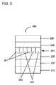
ディスプレイを構成する発光ダイオードなどの光を発する有機電子デバイスは、多くの様々な種類の電子装置に存在する。そのようなデバイスの全てにおいて、有機電気活性層は2層の電気接触層の間に挟まれている。電気接触層の少なくとも1層は光透過性であるため、光は電気接触層を通過することができる。有機電気活性層は、電気接触層の間に電気が加えられると、光透過性電気接触層を通して光を発する。 Organic electronic devices that emit light, such as light emitting diodes that make up displays, exist in many different types of electronic devices. In all such devices, the organic electroactive layer is sandwiched between two electrical contact layers. Since at least one of the electrical contact layers is light transmissive, light can pass through the electrical contact layer. The organic electroactive layer emits light through the light transmissive electrical contact layer when electricity is applied between the electrical contact layers.
発光ダイオード中の電気活性成分として有機エレクトロルミネッセンス化合物が使用されることは周知である。アントラセン、チアジアゾール誘導体およびクマリン誘導体などの単純な有機分子がエレクトロルミネセンスを示すことが知られている。半導性共役ポリマーもエレクトロルミネセント成分として使用されており、例えば、米国特許第5,247,190号明細書、同第5,408,109号明細書および欧州特許出願公開第443861号明細書に開示されている。多くの場合、エレクトロルミネセント化合物は、ホスト材料中にドーパントとして存在する。 It is well known that organic electroluminescent compounds are used as electroactive components in light emitting diodes. Simple organic molecules such as anthracene, thiadiazole derivatives and coumarin derivatives are known to exhibit electroluminescence. Semiconducting conjugated polymers have also been used as electroluminescent components, for example, U.S. Pat. Nos. 5,247,190, 5,408,109 and EP-A-443861. Is disclosed. In many cases, the electroluminescent compound is present as a dopant in the host material.
電子デバイスのための新規材料が引き続き必要とされている。 There is a continuing need for new materials for electronic devices.
(a)380〜750nmで発光極大を有するエレクトロルミネセンスが可能なドーパントと、(b)少なくとも1単位の式I (A) a dopant capable of electroluminescence having an emission maximum at 380 to 750 nm, and (b) at least one unit of formula I

(式中、Ar1、Ar2およびAr3は、同一であるか、または異なっており、H、Dまたはアリール基であるが、ただし、Ar1、Ar2およびAr3のうちの少なくとも2つがアリールであり、かつAr1、Ar2およびAr3のいずれもインドロカルバゾール部分を含まない)を有する第1のホスト化合物と、
(c)第2のホスト化合物とを含んでなる組成物を提供する。Wherein Ar1 , Ar2 and Ar3 are the same or different and are H, D or an aryl group, provided that at least two of Ar1 , Ar2 and Ar3 are A first host compound having an aryl and Ar1 , Ar2 and Ar3 do not contain an indolocarbazole moiety),
(C) A composition comprising a second host compound is provided.
上記組成物を含んでなる電気活性層を含んでなる電子デバイスも提供される。 There is also provided an electronic device comprising an electroactive layer comprising the composition.
少なくとも1単位の式Iを有する化合物を含んでなる有機半導体層を含んでなる薄膜トランジスタも提供される。 Also provided is a thin film transistor comprising an organic semiconductor layer comprising a compound having at least one unit of formula I.
本明細書において提示される概念の理解を深めるために、添付の図面に実施形態を説明する。 In order to better understand the concepts presented herein, embodiments are described in the accompanying drawings.
当業者は、図面中の物体が、平易かつ明快にするために示されており、必ずしも縮尺通りに描かれているわけではないことを認識する。例えば、実施形態の理解を高めるために、図面中の一部の物体の寸法が他の物体よりも誇張されていてもよい。 Those skilled in the art recognize that the objects in the drawings are shown for simplicity and clarity and have not necessarily been drawn to scale. For example, in order to enhance the understanding of the embodiment, the dimensions of some objects in the drawings may be exaggerated more than other objects.
多くの態様および実施形態を以上に説明しているが、これらは例示的で非限定的なものである。本明細書を読めば、本発明の範囲から逸脱することなく他の態様および実施形態が可能であることは当業者に認識される。 Many aspects and embodiments have been described above and are exemplary and not limiting. After reading this specification, skilled artisans will recognize that other aspects and embodiments are possible without departing from the scope of the invention.
いずれか1つまたはそれ以上の実施形態のその他の特徴および利点は、以下の詳細な説明および特許請求の範囲から明らかとなるであろう。詳細な説明では、最初に用語の定義および説明を記載し、続いて電気活性組成物、電子デバイス、そして最後に実施例を記載する。 Other features and advantages of any one or more embodiments will be apparent from the following detailed description and from the claims. In the detailed description, definitions and explanations of terms are given first, followed by electroactive compositions, electronic devices, and finally examples.
1.用語の定義および説明
以下に記載される実施形態の詳細を記載する前に、一部の用語について定義または説明を行う。1. Definitions and Explanations of Terms Before describing the details of the embodiments described below, some terms are defined or explained.
本明細書に使用される場合、用語「脂肪族環」は、非局在化パイ電子を有さない環基を意味することが意図される。いくつかの実施形態において、脂肪族環は不飽和を有さない。いくつかの実施形態において、環は1つの二重結合または三重結合を有する。 As used herein, the term “aliphatic ring” is intended to mean a cyclic group having no delocalized pi electrons. In some embodiments, the aliphatic ring has no unsaturation. In some embodiments, the ring has one double or triple bond.
用語「アルコキシ」は、Rがアルキルである基RO−を指す。 The term “alkoxy” refers to the group RO—, where R is alkyl.
用語「アルキル」は、1つの結合点を有する脂肪族炭化水素から誘導される基を意味することが意図され、直鎖、分枝、または環式基を含む。この用語は、ヘテロアルキルを含むことが意図される。用語「炭化水素アルキル」は、ヘテロ原子を有さないアルキル基を指す。用語「重水素化アルキル」は、Dによって置き換えられる少なくとも1個の利用可能なHを有する炭化水素アルキルである。いくつかの実施形態において、アルキル基は1〜20個の炭素原子を有する。 The term “alkyl” is intended to mean a group derived from an aliphatic hydrocarbon having one point of attachment, and includes straight chain, branched, or cyclic groups. The term is intended to include heteroalkyl. The term “hydrocarbon alkyl” refers to an alkyl group having no heteroatoms. The term “deuterated alkyl” is a hydrocarbon alkyl having at least one available H replaced by D. In some embodiments, the alkyl group has 1-20 carbon atoms.
用語「アリール」は、1つの結合点を有する芳香族炭化水素から誘導される基を意味することが意図される。用語「芳香族化合物」は、非局在化パイ電子を有する少なくとも1個の不飽和環基を含んでなる有機化合物を意味することが意図される。この用語は、ヘテロアリールを含むことが意図される。用語「炭化水素アリール」は、環にヘテロ原子を有さない芳香族化合物を意味することが意図される。用語アリールは、単環を有する基、および単結合で結合可能であるか、または一緒に縮合可能である複数の環を有する基を含む。用語「重水素化アリール」は、Dによって置き換えられた、アリールに直接結合した少なくとも1個の利用可能なHを有するアリール基を指す。用語「アリーレン」は、2つの結合点を有する芳香族炭化水素から誘導される基を意味することが意図される。いくつかの実施形態において、アリール基は3〜60個の炭素原子を有する。 The term “aryl” is intended to mean a group derived from an aromatic hydrocarbon having one point of attachment. The term “aromatic compound” is intended to mean an organic compound comprising at least one unsaturated ring group having delocalized pi electrons. The term is intended to include heteroaryl. The term “hydrocarbon aryl” is intended to mean an aromatic compound having no heteroatoms in the ring. The term aryl includes groups having a single ring and groups having multiple rings that can be joined by a single bond or fused together. The term “deuterated aryl” refers to an aryl group having at least one available H directly attached to aryl, replaced by D. The term “arylene” is intended to mean a group derived from an aromatic hydrocarbon having two points of attachment. In some embodiments, the aryl group has 3 to 60 carbon atoms.
用語「アリールオキシ」は、Rがアリールである基RO−を指す。 The term “aryloxy” refers to the group RO— where R is aryl.
用語「カルバゾリル」は、以下の単位 The term “carbazolyl” means the unit
(式中、RはH、D、アルキル、アリールまたは結合点であり、かつYはアリールまたは結合点である)を含有する基を指す。用語N−カルバゾリルは、Yが結合点であるカルバゾリル基を指す。Wherein R is H, D, alkyl, aryl or a point of attachment, and Y is an aryl or point of attachment. The term N-carbazolyl refers to a carbazolyl group where Y is the point of attachment.
用語「化合物」は、物理的手段で分離することができない原子からさらになる分子から構成される荷電していない物質を意味することが意図される。句「隣接する」は、デバイス中の層に関して使用される場合、ある層が別の層のすぐ次にあることを必ずしも意味するというわけではない。他方、句「隣接するR基」は、化学的式中で互いに隣にあるR基(すなわち結合している原子上にあるR基)を指すために使用される。 The term “compound” is intended to mean an uncharged substance composed of molecules further composed of atoms that cannot be separated by physical means. The phrase “adjacent” when used in reference to a layer in a device does not necessarily mean that one layer is immediately next to another layer. On the other hand, the phrase “adjacent R groups” is used to refer to R groups that are next to each other in a chemical formula (ie, R groups that are on the atoms to which they are attached).
用語「重水素化」は、少なくとも1個のHがDによって置き換えられたことを意味することが意図される。重水素は天然存在量の少なくとも100倍で存在する。化合物Xの「重水素化類似体」は、化合物Xと同じ構造を有するが、少なくとも1個のDが水素を置換している。 The term “deuteration” is intended to mean that at least one H has been replaced by D. Deuterium is present at least 100 times its natural abundance. A “deuterated analog” of Compound X has the same structure as Compound X, but at least one D replaces hydrogen.
用語「ドーパント」は、ホスト材料を含む層中で、そのような材料を含まない場合の層の放射線放出の電子的特徴または波長、受容、またはフィルタリングと比較して、層の放射線放出の電子的特徴または標的波長、受容、またはフィルタリングを変化させる材料を意味することが意図される。 The term “dopant” refers to a layer's radiation emitting electronic characteristics in a layer that includes a host material, as compared to the electronic characteristics or wavelength, acceptance, or filtering of the radiation emission of the layer without such material. It is intended to mean a material that changes characteristics or target wavelength, acceptance, or filtering.
用語「電気活性」は、層または材料に関して言及される場合、電子または電気放射特性を示す層または材料を意味することが意図される。電子デバイスにおいて、電気活性材料は、デバイスの作動を電子的に促進する。電気活性材料の例には、限定されないが、電子または正孔のいずれかであることができる電荷を伝達するか、注入するか、輸送するか、ブロックする材料、および放射線を放出するか、または放射線を受け取るときに電子正孔対の濃度の変化を示す材料が含まれる。不活性材料の例には、限定されないが、平坦化材料、絶縁材料および環境障壁材料が含まれる。 The term “electroactive”, when referred to with respect to a layer or material, is intended to mean a layer or material that exhibits electronic or electrical emission properties. In electronic devices, the electroactive material electronically facilitates device operation. Examples of electroactive materials include, but are not limited to, materials that transmit, inject, transport, block, and emit radiation, which can be either electrons or holes, or Included are materials that exhibit a change in the concentration of electron-hole pairs when receiving radiation. Examples of inert materials include, but are not limited to, planarization materials, insulating materials, and environmental barrier materials.
接頭辞「ヘテロ」は、1個またはそれ以上の炭素原子が異なる原子に置き換えられたことを示す。いくつかの実施形態において、異なる原子は、N、OまたはSである。 The prefix “hetero” indicates that one or more carbon atoms have been replaced with a different atom. In some embodiments, the different atom is N, O, or S.
用語「ホスト材料」は、ドーパントが添加されていてもよい材料を意味することが意図される。ホスト材料は、電子的特性、もしくは放射線の放出、受容、またはフィルタリングする能力を有していてもよく、または有さなくてもよい。いくつかの実施形態において、ホスト材料はより高濃度で存在する。 The term “host material” is intended to mean a material to which a dopant may be added. The host material may or may not have electronic properties or the ability to emit, accept or filter radiation. In some embodiments, the host material is present at a higher concentration.
用語「インドロカルバゾール」は、以下の部分 The term “indolocarbazole” has the following parts:
(式中、Qは、窒素含有環がいずれかの配向で縮合するフェニル環を表し、かつ、RはHまたは置換基を表す)を指す。(Wherein Q represents a phenyl ring on which the nitrogen-containing ring is condensed in any orientation, and R represents H or a substituent).
用語「層」は、用語「膜」と同義的に使用され、所望の領域を覆うコーティングを意味する。この用語は大きさによって限定されることはない。この領域は、デバイス全体の大きさであることが可能であり、実際の視覚的表示などの特殊機能領域の小ささ、または1つのサブピクセルの小ささであることも可能である。層および膜は、気相堆積、液相堆積(連続的技術および不連続的技術)などの従来の任意の堆積技術および熱転写によって形成することができる。連続堆積技術としては、スピンコーティング、グラビアコーティング、カーテンコーティング、浸漬コーティング、スロットダイコーティング、スプレーコーティング、および連続ノズルコーティングが挙げられるが、これらに限定されるものではない。不連続堆積技術としては、インクジェット印刷、グラビア印刷、およびスクリーン印刷が挙げられるが、これらに限定されるものではない。 The term “layer” is used interchangeably with the term “film” and refers to a coating covering a desired area. The term is not limited by size. This area can be the size of the entire device, it can be as small as a special function area such as an actual visual display, or as small as one sub-pixel. Layers and films can be formed by any conventional deposition technique such as vapor deposition, liquid deposition (continuous and discontinuous techniques) and thermal transfer. Continuous deposition techniques include, but are not limited to, spin coating, gravure coating, curtain coating, dip coating, slot die coating, spray coating, and continuous nozzle coating. Discontinuous deposition techniques include, but are not limited to, ink jet printing, gravure printing, and screen printing.
用語「ルミネセンス」は、発光体の温度のみに起因することが不可能であるが、化学反応、電子衝撃、電磁放射および電界などの原因から生じる発光を指す。用語「ルミネセント」は、ルミネセンスが可能な材料を指す。The term “luminescence” refers to luminescence that cannot be attributed solely to the temperature of the illuminant, but arises from causes such as chemical reactions, electron impact, electromagnetic radiation and electric fields. The term “luminescent” refers to a material capable of luminescence.
用語「N−複素環」は、芳香環に少なくとも1個の窒素を有する複素環式芳香族化合物または基を指す。 The term “N-heterocycle” refers to a heteroaromatic compound or group having at least one nitrogen in the aromatic ring.
用語「O−複素環」は、芳香環に少なくとも1個の酸素を有する複素環式芳香族化合物または基を指す。 The term “O-heterocycle” refers to a heteroaromatic compound or group having at least one oxygen in the aromatic ring.
用語「N,O,S−複素環」は、芳香環に少なくとも1個のN、OもしくはSであるヘテロ原子を有する複素環式芳香族化合物または基を指す。N,O,S−複素環は、2種以上のヘテロ原子を有してもよい。 The term “N, O, S-heterocycle” refers to a heterocyclic aromatic compound or group having at least one heteroatom that is N, O or S in the aromatic ring. The N, O, S-heterocycle may have two or more heteroatoms.
用語「有機電子デバイス」または単に「電子デバイス」は、1種またはそれ以上の有機半導体層または材料を含むデバイスを意味することが意図される。 The term “organic electronic device” or simply “electronic device” is intended to mean a device comprising one or more organic semiconductor layers or materials.
用語「有機金属」は、炭素−金属結合がある材料を指す。 The term “organometallic” refers to a material with a carbon-metal bond.
用語「光活性」は、印加電圧によって活性化されるときに光を発する(発光ダイオードまたは化学電池など)か、または印加バイアス電圧の有無にかかわらず放射エネルギーに反応して信号を生じる(光検出器または光電池など)材料または層を意味することが意図される。 The term “photoactive” either emits light when activated by an applied voltage (such as a light emitting diode or a chemical cell) or produces a signal in response to radiant energy with or without an applied bias voltage (photodetection). Is intended to mean a material or layer.
用語「S−複素環」は、芳香環に少なくとも1個の硫黄を有する複素環式芳香族化合物または基を指す。 The term “S-heterocycle” refers to a heteroaromatic compound or group having at least one sulfur in the aromatic ring.
用語「シロキサン」は、RがH、D、C1〜20アルキルまたはフルオロアルキルである基(RO)3Si−を指す。 The term “siloxane” refers to the group (RO) 3 Si— where R is H, D, C 1-20 alkyl or fluoroalkyl.
用語「シリル」は、RがH、D、C1〜20アルキル、フルオロアルキルまたはアリールである基R3Si−を指す。いくつかの実施形態において、Rアルキル基中の1個またはそれ以上の炭素はSiに置き換えられる。 The term “silyl” refers to the group R 3 Si—, where R is H, D, C 1-20 alkyl, fluoroalkyl or aryl. In some embodiments, one or more carbons in the R alkyl group are replaced with Si.
特に明記しない限り、全ての基は未置換であることも、置換されていることも可能である。いくつかの実施形態において、置換基は、D、ハロゲン化物、アルキル、アルコキシ、アリール、アリールオキシ、シアノ、シリル、シロキサン、およびRがアルキルまたはアリールであるNR2からなる群から選択される。 Unless otherwise specified, all groups can be unsubstituted or substituted. In some embodiments, the substituent is selected from the group consisting of D, halide, alkyl, alkoxy, aryl, aryloxy, cyano, silyl, siloxane, and NR2 where R is alkyl or aryl.
特に定義しない限り、本明細書において使用される全ての技術用語および科学用語は、本発明が属する技術分野の当業者によって一般に理解されている意味と同じ意味を有する。本明細書に記載されているものと類似または同等の方法および材料を、本発明の実施または試験において使用することができるが、好適な方法および材料については以下に説明する。本明細書において言及されるいずれの刊行物、特許出願、特許、およびその他の参考文献も、それらの記載内容全体が援用される。矛盾が生じる場合には、定義を含めて本明細書に従うものとする。さらに、材料、方法、および実施例は、単に説明的なものであって、限定を意図したものではない。 Unless defined otherwise, all technical and scientific terms used herein have the same meaning as commonly understood by one of ordinary skill in the art to which this invention belongs. Although methods and materials similar or equivalent to those described herein can be used in the practice or testing of the present invention, suitable methods and materials are described below. Any publications, patent applications, patents, and other references mentioned herein are incorporated by reference in their entirety. In case of conflict, the present specification, including definitions, will control. In addition, the materials, methods, and examples are illustrative only and not intended to be limiting.
全体を通して、周期表の族が左から右へ1から18まで番号づけられるIUPAC番号方式が使用される(CRC Handbook of Chemistry and Physics,81st Edition,2000)。本明細書中、対象の実施形態が、特定の特徴または要素を含んでなるか、含むか、含有するか、有するか、それらから構成されるかものとして明示または記載される使用の文脈によって、明白に明示されるか、または逆に示されない限り、明白に明示されるか、または記載されるものに加えて、1つまたはそれ以上の特徴または要素が実施形態に存在してもよい。開示された本明細書の対象の別の実施形態は、特定の特徴または要素から本質的になるものとして記載され、そのような実施形態においては、実施形態の作動原理または顕著な特徴を大いに変更する特徴または要素は存在しない。開示された本明細書の対象のさらに別の実施形態は、特定の特徴または要素からなるものとして記載され、そのような実施形態においては、またはそれらのごくわずかな変形形態においては、具体的に記述または記載された特徴または要素のみが存在する。 Throughout, an IUPAC numbering system is used in which periodic table families are numbered from left to right from 1 to 18 (CRC Handbook of Chemistry and Physics, 81st Edition, 2000). As used herein, subject embodiments are explicitly or described as comprising, including, containing, having, or consisting of particular features or elements, depending on the context of use. Unless explicitly stated or indicated otherwise, one or more features or elements may be present in an embodiment in addition to those explicitly shown or described. Other embodiments of the disclosed subject matter are described as consisting essentially of particular features or elements, and in such embodiments, the working principles or salient features of the embodiments are greatly modified. No feature or element exists. Further embodiments of the subject matter disclosed herein are described as consisting of particular features or elements, and in such embodiments, or in only a few variations thereof, are specifically Only the features or elements described or described are present.
さらに、反対の意味で明記されない限り、「または」は、包含的な「または」を意味するのであって、排他的な「または」を意味するのではない。例えば、条件AまたはBが満たされるのは、Aが真であり(または存在し)Bが偽である(または存在しない)、Aが偽であり(または存在せず)Bが真である(または存在する)、ならびにAおよびBの両方が真である(または存在する)のいずれか1つによってである。 Further, unless stated to the contrary, “or” means an inclusive “or” and not an exclusive “or”. For example, condition A or B is satisfied when A is true (or present) and B is false (or does not exist), A is false (or does not exist) and B is true ( Or both) and both A and B are true (or present).
また、本発明の要素および成分を説明するために「a」または「an」も使用されている。これは単に便宜的なものであり、本発明の一般的な意味を提供するために行われている。この記述は、1つまたは少なくとも1つを含むものと読むべきであり、明らかにそうではない場合を除けば、単数形は複数形も含んでいる。 “A” or “an” is also used to describe elements and components of the present invention. This is merely for convenience and is done to provide a general sense of the invention. This description should be read to include one or at least one and the singular also includes the plural unless it is clearly not the case.
2.電気活性組成物
電気活性組成物は、
(a)380〜750nmで発光極大を有するエレクトロルミネセンスが可能なドーパントと、(b)少なくとも1単位の式I2. Electroactive composition The electroactive composition is
(A) a dopant capable of electroluminescence having an emission maximum at 380 to 750 nm, and (b) at least one unit of formula I
(式中、Ar1、Ar2およびAr3は、同一であるか、または異なっており、H、Dまたはアリール基であるが、ただし、Ar1、Ar2およびAr3のうちの少なくとも2つがアリールであり、かつAr1、Ar2およびAr3のいずれもインドロカルバゾール部分を含まない)を有するホスト化合物と、
(c)第2のホスト化合物とを含んでなる。Wherein Ar1 , Ar2 and Ar3 are the same or different and are H, D or an aryl group, provided that at least two of Ar1 , Ar2 and Ar3 are A host compound having an aryl and Ar1 , Ar2 and Ar3 do not contain an indolocarbazole moiety),
(C) a second host compound.
「少なくとも1単位を有する」とは、ホストが、式Iを有する化合物、2単位以上の式Iを有するオリゴマーもしくはホモポリマー、または式Iの単位および1種もしくはそれ以上の追加のモノマーの単位を有するコポリマーであることができることを意味する。オリゴマー、ホモポリマーおよびコポリマーの単位は、置換基を通して結合可能である。 “Having at least one unit” means that the host comprises a compound having formula I, two or more units of an oligomer or homopolymer having formula I, or a unit of formula I and one or more additional monomer units. It means that it can be a copolymer having. Oligomeric, homopolymeric and copolymeric units can be linked through substituents.
少なくとも1単位の式Iを有する化合物は、任意の色の発光を有するドーパントのためのコホストとして使用することができる。いくつかの実施形態において、少なくとも1単位の式Iを有する化合物を、有機金属エレクトロルミネセント材料のためのコホストとして使用する。 A compound having at least one unit of Formula I can be used as a cohost for dopants having any color emission. In some embodiments, at least one unit of the compound having Formula I is used as a cohost for the organometallic electroluminescent material.
いくつかの実施形態において、光活性組成物は、(a)380〜750nmで発光極大を有するエレクトロルミネセンスが可能な光活性ドーパントと、(b)少なくとも1単位の式Iを有するホスト化合物と、(c)第2のホスト化合物とから本質的になる。 In some embodiments, the photoactive composition comprises (a) a photoactive dopant capable of electroluminescence having an emission maximum at 380-750 nm, and (b) a host compound having at least one unit of Formula I; (C) essentially consisting of a second host compound.
組成物に存在するドーパントの量は、一般に、光活性組成物の全重量に基づき、3〜20重量%、いくつかの実施形態においては5〜15重量%の範囲にある。式Iを有する第1のホスト対第2のホストの比率は、一般に、1:20〜20:1、いくつかの実施形態においては5:15〜15:5の範囲である。いくつかの実施形態において、式Iを有する第1のホスト材料は、全ホスト材料の少なくとも50重量%、いくつかの実施形態においては少なくとも70重量%である。 The amount of dopant present in the composition is generally in the range of 3-20% by weight, and in some embodiments 5-15% by weight, based on the total weight of the photoactive composition. The ratio of the first host having the formula I to the second host is generally in the range of 1:20 to 20: 1, in some embodiments 5:15 to 15: 5. In some embodiments, the first host material having Formula I is at least 50% by weight of the total host material, and in some embodiments at least 70% by weight.
(a)ドーパント
光活性層のドーパントとして使用可能なエレクトロルミネセント(「EL」)材料としては、限定されないが、小分子有機ルミネセント化合物、ルミネセント金属錯体、共役ポリマーおよびそれらの混合物が含まれる。小分子ルミネセント有機化合物の例としては、限定されないが、クリセン、ピレン、ペリレン、ルブレン、クマリン、アントラセン、チアジアゾール、それらの誘導体およびそれらの混合物が含まれる。金属錯体の例としては、限定されないが、金属キレート化オキシノイド化合物、ならびにイリジウムおよび白金などの金属のシクロメタレート化された錯体が含まれる。共役ポリマーの例としては、限定されないが、ポリ(フェニレンビニレン)、ポリフルオレン、ポリ(スピロビフルオレン)、ポリチオフェン、ポリ(p−フェニレン)、それらのコポリマー、およびそれらの混合物が含まれる。(A) Dopants Electroluminescent (“EL”) materials that can be used as dopants in the photoactive layer include, but are not limited to, small molecule organic luminescent compounds, luminescent metal complexes, conjugated polymers, and mixtures thereof. . Examples of small molecule luminescent organic compounds include, but are not limited to, chrysene, pyrene, perylene, rubrene, coumarin, anthracene, thiadiazole, derivatives thereof and mixtures thereof. Examples of metal complexes include, but are not limited to, metal chelated oxinoid compounds, and cyclometallated complexes of metals such as iridium and platinum. Examples of conjugated polymers include, but are not limited to, poly (phenylene vinylene), polyfluorene, poly (spirobifluorene), polythiophene, poly (p-phenylene), copolymers thereof, and mixtures thereof.
赤色発光材料の例としては、限定されないが、フェニルキノリンまたはフェニルイソキノリン配位子を有するIrの錯体、ペリフランテン、フルオランテンおよびペリレンが含まれる。赤色発光材料は、例えば、米国特許第6,875,524号明細書および米国特許出願公開第2005−0158577号明細書に開示されている。 Examples of red light emitting materials include, but are not limited to, Ir complexes with phenylquinoline or phenylisoquinoline ligands, perifanthene, fluoranthene, and perylene. Red light emitting materials are disclosed, for example, in US Pat. No. 6,875,524 and US Patent Application Publication No. 2005-0158577.
緑色発光材料の例としては、限定されないが、フェニルピリジン配位子を有するIrの錯体、ビス(ジアリールアミノ)アントラセンおよびポリフェニレンビニレンポリマーが含まれる。緑色発光材料は、例えば、国際公開第2007/021117号パンフレットに開示されている。 Examples of green light emitting materials include, but are not limited to, Ir complexes with phenylpyridine ligands, bis (diarylamino) anthracenes, and polyphenylene vinylene polymers. The green light emitting material is disclosed in, for example, International Publication No. 2007/021117.
青色発光材料の例としては、限定されないが、フェニルピリジンまたはフェニルイミダゾール配位子を有するIrの錯体、ジアリールアントラセン、ジアミノクリセン、ジアミノピレンおよびポリフルオレンポリマーが含まれる。青色発光材料は、例えば、米国特許第6,875,524号明細書、ならびに米国特許出願公開第2007−0292713号明細書および同第2007−0063638号明細書に開示されている。 Examples of blue light-emitting materials include, but are not limited to, Ir complexes with phenylpyridine or phenylimidazole ligands, diarylanthracenes, diaminochrysene, diaminopyrene and polyfluorene polymers. Blue light-emitting materials are disclosed, for example, in US Pat. No. 6,875,524 and US Patent Publication Nos. 2007-0292713 and 2007-0063638.
いくつかの実施形態において、ドーパントは有機金属錯体である。いくつかの実施形態において、有機金属錯体は、シクロメタレート化される。「シクロメタレート化される」とは、錯体が少なくとも2点で金属と結合する少なくとも1個の配位子を含有して、少なくとも1個の炭素−金属結合を有する少なくとも1個の5−または6員環を形成することを意味する。いくつかの実施形態において、金属はイリジウムまたは白金である。いくつかの実施形態において、有機金属錯体は電気的に中性であり、そして式IrL3を有するイリジウムのトリスシクロメタレート化錯体であるか、または式IrL2Yを有するイリジウムのビスシクロメタレート化錯体である。いくつかの実施形態において、Lは、炭素原子および窒素原子によって配位するモノアニオン二座シクロメタレート化配位子である。いくつかの実施形態において、Lは、アリールがフェニルまたはナフチルであり、そしてN−複素環がピリジン、キノリン、イソキノリン、ジアジン、ピロール、ピラゾールまたはイミダゾールであるアリールN−複素環である。いくつかの実施形態において、Yはモノアニオン二座配位子である。いくつかの実施形態において、Lはフェニルピリジン、フェニルキノリンまたはフェニルイソキノリンである。いくつかの実施形態において、Yは、β−ジエノレート、ジケチミン、ピコリネートまたはN−アルコキシピラゾールである。配位子は未置換であっても、またはF、D、アルキル、ペルフルオロアルキル、アルコキシル、アルキルアミノ、アリールアミノ、CN、シリル、フルオロアルコキシルもしくはアリール基で置換されてもよい。 In some embodiments, the dopant is an organometallic complex. In some embodiments, the organometallic complex is cyclometallated. “Cyclometallated” means at least one 5- or at least one carbon-metal bond containing at least one ligand that binds the metal at least two points. It means forming a 6-membered ring. In some embodiments, the metal is iridium or platinum. In some embodiments, the organometallic complex is electrically neutral and is a triscyclometallated complex of iridium having the formula IrL3 or a biscyclometalated complex of iridium having the formula IrL2Y. is there. In some embodiments, L is a monoanionic bidentate cyclometallated ligand coordinated by carbon and nitrogen atoms. In some embodiments, L is an aryl N-heterocycle wherein aryl is phenyl or naphthyl and the N-heterocycle is pyridine, quinoline, isoquinoline, diazine, pyrrole, pyrazole or imidazole. In some embodiments, Y is a monoanionic bidentate ligand. In some embodiments, L is phenylpyridine, phenylquinoline or phenylisoquinoline. In some embodiments, Y is β-dienolate, diketimine, picolinate or N-alkoxypyrazole. The ligand may be unsubstituted or substituted with an F, D, alkyl, perfluoroalkyl, alkoxyl, alkylamino, arylamino, CN, silyl, fluoroalkoxyl or aryl group.
いくつかの実施形態において、ドーパントは、イリジウムまたは白金のシクロメタレート化錯体である。そのような材料は、例えば、米国特許第6,670,645号明細書、国際公開第03/063555号パンフレット、同第2004/016710号パンフレットおよび同第03/040257号パンフレットに開示されている。 In some embodiments, the dopant is a iridium or platinum cyclometallated complex. Such materials are disclosed, for example, in US Pat. No. 6,670,645, WO 03/063555, 2004/0167710, and 03/040257.
いくつかの実施形態において、ドーパントは、式Ir(L1)a(L2)b(L3)c
(式中、
L1は、炭素および窒素によって配位するシクロメタレート化されたモノアニオン二座配位子であり、
L2は、炭素によって配位しないモノアニオン二座配位子であり、
L3は、単座配位子であり、
aは1〜3であり、
bおよびcは、独立して0〜2であり、そして
a、bおよびcは、イリジウムが六配位であり、錯体が電気的に中性であるように選択される)を有する錯体である。In some embodiments, the dopant is of the formula Ir (L1) a (L2) b (L3) c
(Where
L1 is a cyclometallated monoanionic bidentate ligand coordinated by carbon and nitrogen;
L2 is a monoanionic bidentate ligand that is not coordinated by carbon;
L3 is a monodentate ligand;
a is 1-3,
b and c are independently 0 to 2 and a, b and c are complexes with iridium selected to be hexacoordinate and the complex is electrically neutral) .
式のいくつかの例には、限定されないが、Ir(L1)3、Ir(L1)2(L2)およびIr(L1)2(L3)(L3’)(式中、L3はアニオンであり、そしてL3’は非イオンである)が含まれる。 Some examples of the formula include, but are not limited to, Ir (L1) 3, Ir (L1) 2 (L2) and Ir (L1) 2 (L3) (L3 ′) where L3 is an anion, And L3 ′ is non-ionic).
L1配位子の例には、限定されないが、フェニルピリジン、フェニルキノリン、フェニルピリミジン、フェニルピラゾール、チエニルピリジン、チエニルキノリンおよびチエニルピリミジンが含まれる。本明細書に使用される場合、用語「キノリン」は、特記しない限り、「イソキノリン」を含む。フッ素化誘導体は、1種またはそれ以上のフッ素置換基を有することができる。いくつかの実施形態において、1〜3個のフッ素置換基が配位子の非窒素環上にある。 Examples of L1 ligands include, but are not limited to, phenylpyridine, phenylquinoline, phenylpyrimidine, phenylpyrazole, thienylpyridine, thienylquinoline and thienylpyrimidine. As used herein, the term “quinoline” includes “isoquinoline” unless otherwise indicated. The fluorinated derivative can have one or more fluorine substituents. In some embodiments, 1 to 3 fluorine substituents are on the non-nitrogen ring of the ligand.
モノアニオン二座配位子、L2は、金属配位化学において周知である。一般に、これらの配位子は、配位原子としてN、O、PまたはSを有し、イリジウムに配位する場合は5−または6員環を形成する。適切な配位基には、アミノ、イミノ、アミド、アルコキシド、カルボキシレート、ホスフィノ、チオレートなどが含まれる。これらの配位子のための適切な親化合物の例は、β−ジカルボニル(β−エノレート配位子)ならびにそれらのNおよびS類似体、アミノカルボン酸(アミノカルボキシレート配位子)、ピリジンカルボン酸(イミノカルボキシレート配位子)、サリチル酸誘導体(サリチレート配位子)、ヒドロキシキノリン(ヒドロキシキノリネート配位子)およびそれらのS類似体、ならびにホスフィノアルカノール(ホスフィノアルコキシド配位子)が含まれる。 The monoanionic bidentate ligand, L2, is well known in metal coordination chemistry. In general, these ligands have N, O, P or S as coordinating atoms and form a 5- or 6-membered ring when coordinated to iridium. Suitable coordinating groups include amino, imino, amide, alkoxide, carboxylate, phosphino, thiolate and the like. Examples of suitable parent compounds for these ligands are β-dicarbonyl (β-enolate ligand) and their N and S analogs, aminocarboxylic acids (aminocarboxylate ligand), pyridine Carboxylic acids (iminocarboxylate ligands), salicylic acid derivatives (salicylate ligands), hydroxyquinolines (hydroxyquinolinate ligands) and their S analogs, and phosphinoalkanols (phosphinoalkoxide ligands) Is included.
単座配位子L3は、アニオンまたは非イオンであることができる。アニオン配位子には、限定されないが、H−(「水素化物」)および配位原子としてC、OまたはSを有する配位子が含まれる。配位基には、限定されないが、アルコキシド、カルボキシレート、チオカルボキシレート、ジチオカルボキシレート、スルホネート、チオレート、カルバメート、ジチオカルバメート、チオカルバゾンアニオン、スルホンアミドアニオンなどが含まれる。いくつかの場合、β−エノラートおよびホスフィノアルコキシドなどのL2として上記される配位子は、単座配位子として機能することができる。単座配位子は、ハロゲン化物、シアン化物、イソシアン化物、硝酸塩、硫酸塩、ヘキサハロアンチモネートなどの配位アニオンであることもできる。これらの配位子は、一般に商業的に入手可能である。 Monodentate ligand L3 can be anionic or non-ionic. Anionic ligands include, but are not limited to, H — (“hydride”) and ligands having C, O, or S as coordinating atoms. Coordinating groups include, but are not limited to, alkoxides, carboxylates, thiocarboxylates, dithiocarboxylates, sulfonates, thiolates, carbamates, dithiocarbamates, thiocarbazone anions, sulfonamide anions, and the like. In some cases, ligands described above as L2 such as β-enolates and phosphinoalkoxides can function as monodentate ligands. The monodentate ligand can also be a coordinating anion such as halide, cyanide, isocyanide, nitrate, sulfate, hexahaloantimonate. These ligands are generally commercially available.
単座L3配位子は、COまたは単座ホスフィン配位子などの非イオン配位子であることもできる。 The monodentate L3 ligand can also be a nonionic ligand such as CO or a monodentate phosphine ligand.
いくつかの実施形態において、配位子の1個またはそれ以上は、Fおよびフッ素化アルキルからなる群から選択される少なくとも1個の置換基を有する。 In some embodiments, one or more of the ligands have at least one substituent selected from the group consisting of F and fluorinated alkyl.
イリジウム錯体ドーパントは、例えば、米国特許第6,670,645号明細書に記載されるような標準的な合成技術を使用して製造することができる。 Iridium complex dopants can be made using standard synthetic techniques, for example, as described in US Pat. No. 6,670,645.
赤色発光を有する有機金属イリジウム錯体の例としては、限定されないが、以下の化合物D1〜D10が含まれる。 Examples of the organometallic iridium complex having red emission include, but are not limited to, the following compounds D1 to D10.
緑色発光を有する有機金属Ir錯体の例としては、限定されないが、以下の化合物D11〜D33が含まれる。 Examples of organometallic Ir complexes having green emission include, but are not limited to, the following compounds D11 to D33.
青色発光を有する有機金属Ir錯体の例としては、限定されないが、以下の化合物D34〜D51が含まれる。 Examples of the organometallic Ir complex having blue emission include, but are not limited to, the following compounds D34 to D51.
いくつかの実施形態において、ドーパントは小有機ルミネセント化合物である。いくつかの実施形態において、ドーパントは、非ポリマースピロビフルオレン化合物およびフルオランテン化合物からなる群から選択される。 In some embodiments, the dopant is a small organic luminescent compound. In some embodiments, the dopant is selected from the group consisting of non-polymer spirobifluorene compounds and fluoranthene compounds.
いくつかの実施形態において、ドーパントはアリールアミン基を有する化合物である。いくつかの実施形態において、ドーパントは、次式: In some embodiments, the dopant is a compound having an arylamine group. In some embodiments, the dopant has the formula:
(式中、
Aは、それぞれ出現するごとに、同一であるか、または異なっており、3〜60個の炭素原子を有する芳香族基であり、
Q’は、単結合または3〜60個の炭素原子を有する芳香族基であり、
pおよびqは、独立して、1〜6の整数である)から選択される。(Where
Each occurrence of A is the same or different and is an aromatic group having 3 to 60 carbon atoms,
Q ′ is a single bond or an aromatic group having 3 to 60 carbon atoms,
p and q are independently an integer from 1 to 6).
上記式のいくつかの実施形態において、各式のAおよびQ’の少なくとも1個は、少なくとも3つの縮合環を有する。いくつかの実施形態において、pおよびqは1に等しい。 In some embodiments of the above formula, at least one of A and Q 'in each formula has at least 3 fused rings. In some embodiments, p and q are equal to 1.
いくつかの実施形態において、Q’はスチリルまたはスチリルフェニル基である。 In some embodiments, Q 'is a styryl or styrylphenyl group.
いくつかの実施形態において、Q’は、少なくとも2個の縮合環を有する芳香族基である。いくつかの実施形態において、Q’は、ナフタレン、アントラセン、クリセン、ピレン、テトラセン、キサンテン、ペリレン、クマリン、ローダミン、キナクリドンおよびルブレンからなる群から選択される。 In some embodiments, Q 'is an aromatic group having at least two fused rings. In some embodiments, Q 'is selected from the group consisting of naphthalene, anthracene, chrysene, pyrene, tetracene, xanthene, perylene, coumarin, rhodamine, quinacridone and rubrene.
いくつかの実施形態において、Aは、フェニル、ビフェニル、トリル、ナフチル、ナフチルフェニルおよびアントラセニル基からなる群から選択される。 In some embodiments, A is selected from the group consisting of phenyl, biphenyl, tolyl, naphthyl, naphthylphenyl, and anthracenyl groups.
いくつかの実施形態において、ドーパントは次式: In some embodiments, the dopant has the formula:
(式中、
Yは、それぞれ出現するごとに、同一であるか、または異なっており、3〜60個の炭素原子を有する芳香族基であり、
Q’’は、芳香族基、二価トリフェニルアミン残基または単結合である)を有する。(Where
Y is the same or different for each occurrence and is an aromatic group having 3 to 60 carbon atoms;
Q ″ has an aromatic group, a divalent triphenylamine residue or a single bond).
いくつかの実施形態において、ドーパントはアリールアセンである。いくつかの実施形態において、ドーパントは非対称アリールアセンである。 In some embodiments, the dopant is aryl acene. In some embodiments, the dopant is an asymmetric aryl acene.
小分子有機緑色ドーパントのいくつかの例としては、限定されないが、以下の化合物D52〜D59が含まれる。 Some examples of small molecule organic green dopants include, but are not limited to, the following compounds D52-D59.
小分子有機青色ドーパントの例としては、限定されないが、以下の化合物D60〜D67が含まれる。 Examples of small molecule organic blue dopants include, but are not limited to, the following compounds D60-D67.
いくつかの実施形態において、ドーパントは、アミノ置換クリセンおよびアミノ置換アントラセンからなる群から選択される。 In some embodiments, the dopant is selected from the group consisting of amino-substituted chrysene and amino-substituted anthracene.
(b)第1のホスト
第1のホストは、上記式I有する少なくとも1単位を有する化合物である。(B) First Host The first host is a compound having at least one unit having the above formula I.
いくつかの実施形態において、式Iの化合物は少なくとも10%重水素化される。これは、少なくとも10%のHがDによって置き換えられることを意味する。いくつかの実施形態において化合物は少なくとも20%重水素化され、いくつかの実施形態において化合物は少なくとも30%重水素化され、いくつかの実施形態において化合物は少なくとも40%重水素化され、いくつかの実施形態において化合物は少なくとも50%重水素化され、いくつかの実施形態において化合物は少なくとも60%重水素化され、いくつかの実施形態において化合物は少なくとも70%重水素化され、いくつかの実施形態において化合物は少なくとも80%重水素化され、いくつかの実施形態において化合物は少なくとも90%重水素化され、いくつかの実施形態において化合物は100%重水素化される。 In some embodiments, the compound of formula I is at least 10% deuterated. This means that at least 10% of H is replaced by D. In some embodiments, the compound is at least 20% deuterated, in some embodiments the compound is at least 30% deuterated, in some embodiments the compound is at least 40% deuterated, some In some embodiments, the compound is at least 50% deuterated, in some embodiments the compound is at least 60% deuterated, in some embodiments the compound is at least 70% deuterated, and in some embodiments In a form, the compound is at least 80% deuterated, in some embodiments the compound is at least 90% deuterated, and in some embodiments, the compound is 100% deuterated.
いくつかの実施形態において、重水素は、アリール基Ar1〜Ar3の1つまたはそれ以上において存在する。いくつかの実施形態において、重水素は、アリール基上の1つまたはそれ以上の置換基において存在する。In some embodiments, the deuterium is present in one or more aryl groupsAr 1 to Ar3. In some embodiments, deuterium is present at one or more substituents on the aryl group.
式Iのいくつかの実施形態において、アリール基は、フェニル、ナフチル、置換ナフチル、スチリル、カルバゾリル、N,O,S−複素環、それらの重水素化類似体、および式IIの置換基 In some embodiments of Formula I, aryl groups are phenyl, naphthyl, substituted naphthyl, styryl, carbazolyl, N, O, S-heterocycle, deuterated analogs thereof, and substituents of Formula II.
(式中、
R1およびR2は、それぞれ出現するごとに、同一であるか、または異なっており、D、アルキル、アリール、シリル、アルコキシ、アリールオキシ、シアノ、ビニル、アリルもしくはそれらの重水素化類似体であるか、または隣接するR基は一緒に結合して、6員芳香族環を形成することができ、
aは、0〜5の整数であるが、ただし、a=5である場合、d=e=0、
bは、0〜5の整数であるが、ただし、b=5である場合、e=0、
cは0〜5の整数であり、
dは0〜5の整数であり、
eは0または1である)からなる群から選択される。(Where
R1 and R2 are the same or different at each occurrence and are D, alkyl, aryl, silyl, alkoxy, aryloxy, cyano, vinyl, allyl or their deuterated analogs. Any or adjacent R groups can be joined together to form a 6-membered aromatic ring;
a is an integer of 0 to 5, provided that when a = 5, d = e = 0,
b is an integer of 0 to 5, provided that when b = 5, e = 0,
c is an integer of 0 to 5,
d is an integer of 0 to 5;
e is 0 or 1).
式IIのいくつかの実施形態において、d=1である。式IIのいくつかの実施形態において、R1およびR2は、D、アルキルまたはアリールである。いくつかの実施形態において、R2の少なくとも1つは、フェニル、ナフチル、カルバゾリル、ジフェニルカルバゾリル、トリフェニルシリル、ピリジルまたはそれらの重水素化類似体である。いくつかの実施形態において、R2置換基は末端環上にある。In some embodiments of Formula II, d = 1. In some embodiments of Formula II, R1 and R2 are D, alkyl, or aryl. In some embodiments, at least one of R2 is phenyl, naphthyl, carbazolyl, diphenylcarbazolyl, triphenylsilyl, pyridyl, or deuterated analogs thereof. In some embodiments, the R2 substituent is on the terminal ring.
式Iのいくつかの実施形態において、Ar1〜Ar3のうちの1つはHまたはDであり、かつAr1〜Ar3のうちの2つはアリールである。いくつかの実施形態において、アリールは、フェニル、ビフェニル、テルフェニル、ナフチル、ナフチルフェニル、フェニルナフチル、N−カルバゾリルまたはそれらの重水素化類似体である。In some embodiments of Formula I, one of Ar1 -Ar3 is H or D, and two of Ar1 -Ar3 are aryl. In some embodiments, aryl is phenyl, biphenyl, terphenyl, naphthyl, naphthylphenyl, phenylnaphthyl, N-carbazolyl, or deuterated analogs thereof.
式Iのいくつかの実施形態において、Ar1〜Ar3の3つ全てがアリールである。いくつかの実施形態において、アリールはフェニル、ビフェニル、テルフェニル、ナフチル、ナフチルフェニル、フェニルナフチル、N−カルバゾリルまたはそれらの重水素化類似体である。In some embodiments of Formula I, allthree of Ar1 -Ar3 are aryl. In some embodiments, aryl is phenyl, biphenyl, terphenyl, naphthyl, naphthylphenyl, phenylnaphthyl, N-carbazolyl, or deuterated analogs thereof.
式Iのいくつかの実施形態において、Ar1〜Ar3の3つ全てが同一である。式Iのいくつかの実施形態において、Ar1〜Ar3のうちの1つは他の2つとは異なる。式Iのいくつかの実施形態において、Ar1〜Ar3の3つ全てが異なる。In some embodiments of Formula I, allthree of Ar1 -Ar3 are the same. In some embodiments of Formula I, one of Ar1 -Ar3 is different from the other two. In some embodiments of Formula I, allthree of Ar1 -Ar3 are different.
式Iのいくつかの実施形態において、Ar1〜Ar3の少なくとも1つは、N,O,S−複素環である置換基を有する。式Iのいくつかの実施形態において、Ar1〜Ar3の少なくとも1つは、N−複素環である置換基を有する。いくつかの実施形態において、N−複素環は、ピリジン、ピリミジン、トリアジン、ピロールまたはそれらの重水素化類似体である。式Iのいくつかの実施形態において、Ar1〜Ar3の少なくとも1つは、O−複素環である置換基を有する。いくつかの実施形態において、O−複素環は、ジベンゾピラン、ジベンゾフランまたはそれらの重水素化類似体である。式Iのいくつかの実施形態において、Ar1〜Ar3の少なくとも1つは、S−複素環である置換基を有する。いくつかの実施形態において、S−複素環は、ジベンゾチオフェンまたはそれらの重水素化類似体である。In some embodiments of Formula I, at least one of Ar1 -Ar3 has a substituent that is an N, O, S-heterocycle. In some embodiments of Formula I, at least one of Ar1 -Ar3 has a substituent that is an N-heterocycle. In some embodiments, the N-heterocycle is pyridine, pyrimidine, triazine, pyrrole, or deuterated analogs thereof. In some embodiments of Formula I, at least one of Ar1 -Ar3 has a substituent that is an O-heterocycle. In some embodiments, the O-heterocycle is dibenzopyran, dibenzofuran, or a deuterated analog thereof. In some embodiments of Formula I, at least one of Ar1 -Ar3 has a substituent that is an S-heterocycle. In some embodiments, the S-heterocycle is dibenzothiophene or a deuterated analog thereof.
式Iのいくつかの実施形態において、Ar1〜Ar3の少なくとも1つは、フェニル、ナフチル、カルバゾリル、ジフェニルカルバゾリル、トリフェニルシリル、ピリジルまたはそれらの重水素化類似体である置換基を有する。In some embodiments of Formula I, at least one of Ar1 -Ar3 has a substituent that is phenyl, naphthyl, carbazolyl, diphenylcarbazolyl, triphenylsilyl, pyridyl, or a deuterated analog thereof. Have.
いくつかの実施形態において、第1のホストは、1単位の式Iを有する化合物である。 In some embodiments, the first host is a compound having 1 unit of Formula I.
いくつかの実施形態において、第1のホストは、2単位以上のいずれかの式Iを有するオリゴマーまたはホモポリマーである。 In some embodiments, the first host is an oligomer or homopolymer having any two or more units of Formula I.
いくつかの実施形態において、第1のホストは、式Iを有する1個の第1のモノマー単位と、少なくとも1個の第2のモノマー単位とを有するコポリマーである。いくつかの実施形態において、第2のモノマー単位も式Iを有するが、第1のモノマー単位とは異なる。いくつかの実施形態において、第2のモノマー単位はアリーレンである。第2のモノマー単位のいくつかの例には、限定されないが、フェニレン、ナフチレン、トリアリールアミン、フルオレン、N,O,S−複素環、ジベンゾフラン、ジベンゾピラン、ジベンゾチオフェンおよびそれらの重水素化類似体が含まれる。 In some embodiments, the first host is a copolymer having one first monomer unit having Formula I and at least one second monomer unit. In some embodiments, the second monomer unit also has the formula I, but is different from the first monomer unit. In some embodiments, the second monomer unit is arylene. Some examples of second monomer units include, but are not limited to, phenylene, naphthylene, triarylamine, fluorene, N, O, S-heterocycle, dibenzofuran, dibenzopyran, dibenzothiophene and their deuterated analogs. Contains the body.
少なくとも1単位の式Iを有する化合物のいくつかの実施形態において、以下のいずれの組み合わせも存在することが可能である。 In some embodiments of the compound having at least one unit of Formula I, any combination of the following may be present.
(i)重水素化、
(ii)アリール基は、フェニル、ナフチル、置換ナフチル、スチリル、カルバゾリル、N,O,S−複素環、それらの重水素化類似体、および上記で定義された式IIの置換基からなる群から選択される、
(iii)Ar1〜Ar3のうちの1つがHまたはDであり、かつAr1〜Ar3のうちの2つがアリールであるか、あるいはAr1〜Ar3の3つ全てがアリールである、
(iv)Ar1〜Ar3の3つ全てが同一であるか、あるいはAr1〜Ar3の1つは他の2つと異なるか、あるいはAr1〜Ar3の3つ全てが異なる、
(v)Ar1〜Ar3の少なくとも1つは、N,O,S−複素環である置換基を有する、
(vi)化合物は1単位の式Iを有するか、あるいは化合物は、2単位以上のいずれかの式Iを有するオリゴマーまたはホモポリマーであるか、あるいは化合物は、式Iを有する1個の第1のモノマー単位と、少なくとも1個の第2のモノマー単位とを有するコポリマーである。(I) deuteration,
(Ii) an aryl group from the group consisting of phenyl, naphthyl, substituted naphthyl, styryl, carbazolyl, N, O, S-heterocycle, their deuterated analogs, and substituents of formula II as defined above Selected,
(Iii)one of Ar1 to Ar3 is H or D and two of Ar1 to Ar3 are aryl, or allthree of Ar1 to Ar3 are aryl,
(Iv) Allthree of Ar1 to Ar3 are the same, orone of Ar1 to Ar3 is different from the other two, or allthree of Ar1 to Ar3 are different,
(V) At least one of Ar1 to Ar3 has a substituent that is an N, O, S-heterocycle,
(Vi) the compound has one unit of formula I, or the compound is an oligomer or homopolymer having any one or more units of formula I, or the compound has one first having formula I And a copolymer having at least one second monomer unit.
少なくとも1単位の式Iを有する化合物のいくつかの非限定的な例には、以下が含まれる。
化合物H1Some non-limiting examples of compounds having at least one unit of Formula I include:
Compound H1
化合物H2Compound H2
化合物H3Compound H3
化合物H4Compound H4
化合物H5Compound H5
化合物H6Compound H6
化合物H7Compound H7
化合物H8Compound H8
化合物H9Compound H9
化合物H10Compound H10
化合物H11Compound H11
化合物H12Compound H12
化合物H13Compound H13
化合物H14Compound H14
化合物H15Compound H15
化合物H16Compound H16
化合物H17Compound H17
化合物H18Compound H18
化合物H19Compound H19
化合物H20Compound H20
(式中、nは1より大きい整数である)
上記構造において、Phはフェニル基を表す。(Where n is an integer greater than 1)
In the above structure, Ph represents a phenyl group.
少なくとも1単位の式Iを有する化合物は、既知のカップリングおよび置換反応によって調製することができる。そのような反応は周知であり、文献で広範囲に記載されている。典型的な参考文献としては、Yamamoto,Progress in Polymer Science,Vol.17,p1153(1992);Colonら,Journal of Polymer Science,Part A,Polymer chemistry Edition,Vol.28,p.367(1990);米国特許第5,962,631号明細書,および国際公開第00/53565号パンフレット;T.Ishiyamaら,J.Org.Chem.1995 60,7508−7510;M.Murataら,J.Org.Chem.1997 62,6458−6459;M.Murataら,J.Org.Chem.2000 65,164−168;L.Zhu,ら,J.Org.Chem.2003 68,3729−3732;Stille,J.K.Angew.Chem.Int.Ed.Engl.1986,25,508;Kumada,M.Pure.Appl.Chem.1980,52,669;Negishi,E.Acc.Chem.Res.1982,15,340;Hartwig,J.,Synlett 2006,No.9,pp.1283−1294;Hartwig,J.,Nature 455,No.18,pp.314−322;Buchwald,S.L.,ら,Adv.Synth.Catal,2006,348,23−39;Buchwald,S.L.,ら,Acc.Chem.Res.(1998),37,805−818;ならびにBuchwald,S.L.,ら,J.Organomet.Chem.576(1999),125−146が挙げられる。 Compounds having at least one unit of formula I can be prepared by known coupling and substitution reactions. Such reactions are well known and have been extensively described in the literature. Typical references include Yamamoto, Progress in Polymer Science, Vol. 17, p 1153 (1992); Colon et al., Journal of Polymer Science, Part A, Polymer Chemistry Edition, Vol. 28, p. 367 (1990); US Pat. No. 5,962,631 and WO 00/53565; Ishiyama et al. Org. Chem. 1995 60, 7508-7510; Murata et al. Org. Chem. 1997 62, 6458-6459; Murata et al. Org. Chem. 2000 65,164-168; Zhu, et al. Org. Chem. 2003 68, 3729-3732; Stille, J. et al. K. Angew. Chem. Int. Ed. Engl. 1986, 25, 508; Kumada, M .; Pure. Appl. Chem. 1980, 52, 669; Negishi, E .; Acc. Chem. Res. 1982, 15, 340; Hartwig, J. et al. , Synlett 2006, no. 9, pp. 1283-1294; Hartwig, J. et al. , Nature 455, No. 18, pp. 314-322; Buchwald, S .; L. , Et al., Adv. Synth. Catal, 2006, 348, 23-39; Buchwald, S .; L. , Et al., Acc. Chem. Res. (1998), 37, 805-818; and Buchwald, S .; L. , Et al. Organomet. Chem. 576 (1999), 125-146.
重水素化類似体化合物は、重水素化前駆体材料を使用して、同様の方法で調製することができ、または、一般に、三塩化アルミニウムもしくは塩化エチルアルミニウム、またはCF3COOD、DClなどの酸などのルイス酸H/D交換触媒の存在下で、d6−ベンゼンなどの重水素化溶媒で非重水素化化合物を処理することによって調製することができる。重水素化反応は、国際公開第2011−053334号パンフレットとして公開された同時係属出願にも記載されている。 Deuterated analog compounds can be prepared in a similar manner using deuterated precursor materials, or generally such as aluminum trichloride or ethylaluminum chloride, or acids such as CF3COOD, DCl, etc. It can be prepared by treating a non-deuterated compound with a deuterated solvent such as d6-benzene in the presence of a Lewis acid H / D exchange catalyst. The deuteration reaction is also described in a co-pending application published as International Publication No. 2011-053334.
本明細書に記載される化合物は、液相堆積技術を使用して、膜に形成することができる。 The compounds described herein can be formed into films using liquid deposition techniques.
(c)第2のホスト
いくつかの実施形態において、第2のホストは重水素化される。いくつかの実施形態において、第2のホストは少なくとも10%重水素化され、いくつかの実施形態において少なくとも20%重水素化され、いくつかの実施形態において少なくとも30%重水素化され、いくつかの実施形態において少なくとも40%重水素化され、いくつかの実施形態において少なくとも50%重水素化され、いくつかの実施形態において少なくとも60%重水素化され、いくつかの実施形態において少なくとも70%重水素化され、いくつかの実施形態において少なくとも80%重水素化され、いくつかの実施形態において少なくとも90%重水素化される。いくつかの実施形態においては100%重水素化される。(C) Second host In some embodiments, the second host is deuterated. In some embodiments, the second host is at least 10% deuterated, in some embodiments at least 20% deuterated, in some embodiments at least 30% deuterated, some At least 40% deuterated, in some embodiments at least 50% deuterated, in some embodiments at least 60% deuterated, in some embodiments at least 70% deuterated. Hydrogenated, in some embodiments at least 80% deuterated, and in some embodiments at least 90% deuterated. In some embodiments, 100% deuterated.
第2のホスト材料の例には、限定されないが、カルバゾール類、インドロカルバゾール類、クリセン類、フェナントレン類、トリフェニレン類、フェナントロリン類、トリアジン類、ナフタレン類、アントラセン類、キノリン類、イソキノリン類、キノキサリン類、フェニルピリジン類、ベンゾジフラン類、金属キノリネート錯体およびそれらの重水素化類似体が含まれる。 Examples of the second host material include, but are not limited to, carbazoles, indolocarbazoles, chrysene, phenanthrenes, triphenylenes, phenanthrolines, triazines, naphthalenes, anthracenes, quinolines, isoquinolines, quinoxalines , Phenylpyridines, benzodifurans, metal quinolinate complexes and their deuterated analogs.
いくつかの実施形態において、第2のホスト材料は、式III: In some embodiments, the second host material is of formula III:
(式中、
Ar4は、それぞれ出現するごとに、同一であるか、または異なっており、アリールであり、
Qは、多価アリール基および(Where
Ar4 is the same or different for each occurrence and is aryl;
Q is a polyvalent aryl group and
からなる群から選択され、
Tは、(CR’)g、SiR2、S、SO2、PR、PO、PO2、BRおよびRからなる群から選択され、
Rは、それぞれ出現するごとに、同一であるか、または異なっており、アルキル、アリール、シリルまたはそれらの重水素化類似体からなる群から選択され、
R’は、それぞれ出現するごとに、同一であるか、または異なっており、H、D、アルキルとシリルからなる群から選択され、
gは1〜6の整数であり、かつ
mは0〜6の整数である)を有する。Selected from the group consisting of
T is selected from the group consisting of (CR ′)g , SiR2 , S, SO2 , PR, PO, PO2 , BR and R;
Each occurrence of R is the same or different and is selected from the group consisting of alkyl, aryl, silyl, or deuterated analogs thereof;
R ′ is the same or different at each occurrence and is selected from the group consisting of H, D, alkyl and silyl;
g is an integer of 1 to 6, and m is an integer of 0 to 6.
式IIIのいくつかの実施形態において、隣接するAr4基は一緒に結合して、カルバゾールなどの環を形成する。式III中、「隣接する」は、Ar基が同一のNに結合することを意味する。In some embodiments of Formula III, adjacent Ar4 groups are joined together to form a ring such as carbazole. In formula III, “adjacent” means that Ar groups are attached to the same N.
いくつかの実施形態において、Ar4基は、フェニル、ビフェニル、テルフェニル、クオーターフェニル、ナフチル、フェナントリル、ナフチルフェニル、フェナントリルフェニルおよびそれらの重水素化類似体からなる群から独立して選択される。5〜10個のフェニル環を有するクオーターフェニルより高い類似体を使用することもできる。In some embodiments, the Ar4 group is independently selected from the group consisting of phenyl, biphenyl, terphenyl, quarterphenyl, naphthyl, phenanthryl, naphthylphenyl, phenanthrylphenyl, and deuterated analogs thereof. The Higher analogs than quarter phenyl with 5-10 phenyl rings can also be used.
いくつかの実施形態において、少なくとも1つのAr4は、少なくとも1つの置換基を有する。置換基は、ホスト材料の物理的または電子的特性を変更するために存在することが可能である。いくつかの実施形態において、置換基はホスト材料の加工性を改善する。いくつかの実施形態において、置換基は、溶解度を増加させ、かつ/またはホスト材料のTgを増加させる。いくつかの実施形態において、置換基は、アルキル基、アルコキシ基、シリル基、それらの重水素化類似体およびそれらの組み合わせからなる群から選択される。In some embodiments, at least one Ar4 has at least one substituent. Substituents can be present to alter the physical or electronic properties of the host material. In some embodiments, the substituent improves the processability of the host material. In some embodiments, the substituents increase solubility and / or increase the Tg of the host material. In some embodiments, the substituent is selected from the group consisting of alkyl groups, alkoxy groups, silyl groups, deuterated analogs thereof, and combinations thereof.
いくつかの実施形態において、Qは、少なくとも2個の縮合環を有するアリール基である。いくつかの実施形態において、Qは、3〜5個の縮合芳香環を有する。いくつかの実施形態において、Qは、クリセン、フェナントレン、トリフェニレン、フェナントロリン、ナフタレン、アントラセン、キノリン、イソキノリンおよびそれらの重水素化類似体からなる群から選択される。 In some embodiments, Q is an aryl group having at least 2 fused rings. In some embodiments, Q has 3-5 fused aromatic rings. In some embodiments, Q is selected from the group consisting of chrysene, phenanthrene, triphenylene, phenanthroline, naphthalene, anthracene, quinoline, isoquinoline and their deuterated analogs.
いくつかの実施形態において、第2のホストは、式IV In some embodiments, the second host is of formula IV
(式中、
Q’は、次式(Where
Q 'is the following formula
を有する縮合環結合であり、
R3は、それぞれ出現するごとに、同一であるか、または異なっており、D、アルキル、アリール、シリル、アルコキシ、アリールオキシ、シアノ、スチリル、ビニルまたはアリルであり、
R4は、それぞれ出現するごとに、同一であるか、または異なっており、H、D、アルキル、炭化水素アリールまたはスチリルであるか、あるいはR2の両方はN−複素環であり、
R5は、それぞれ出現するごとに、同一であるか、または異なっており、アルキル、アリール、シリル、アルコキシ、アリールオキシ、シアノ、スチリル、ビニルまたはアリルであり、
pは、それぞれ出現するごとに、同一であるか、または異なっており、0〜4の整数である)を有する。A fused ring bond having
Each occurrence of R3 is the same or different and is D, alkyl, aryl, silyl, alkoxy, aryloxy, cyano, styryl, vinyl or allyl;
Each occurrence of R4 is the same or different and is H, D, alkyl, hydrocarbon aryl or styryl, or both R2 are N-heterocycles;
Each occurrence of R5 is the same or different and is alkyl, aryl, silyl, alkoxy, aryloxy, cyano, styryl, vinyl or allyl;
p is the same or different for each occurrence and is an integer from 0 to 4.
用語「縮合環結合」は、任意の配向において、Q基が両窒素含有環に縮合することを示すために使用される。 The term “fused ring bond” is used to indicate that the Q group is fused to both nitrogen-containing rings in any orientation.
3.有機電子デバイス
本明細書に記載の重水素化材料を含んでなる1層またはそれ以上の層を有することから有益となり得る有機電子デバイスとしては、限定されないが、(1)電気エネルギーを放射線に変換するデバイス(例えば、発光ダイオード、発光ダイオードディスプレイ、発光照明器具、またはダイオードレーザー)、(2)電子的プロセスを介して信号を検出するデバイス(例えば、光検出器、光導電セル、フォトレジスタ、光スイッチ、光トランジスタ、光電管、IR検出器)、(3)放射線を電気エネルギーに変換するデバイス(例えば、光起電力デバイスまたは太陽電池)、ならびに(4)1つまたはそれ以上の有機半導体層を含む1つまたはそれ以上の電子部品を含むデバイス(例えば、薄膜トランジスタまたはダイオード)が挙げられる。発明の化合物は、バイオアッセイの酸素感応性インジケータおよびルミネセントインジケータなどの用途でしばしば有用となることが可能性である。3. Organic electronic devices Organic electronic devices that may benefit from having one or more layers comprising the deuterated materials described herein include, but are not limited to: (1) converting electrical energy into radiation (2) devices that detect signals through electronic processes (eg, light detectors, photoconductive cells, photo-resistors, light) Switches, phototransistors, phototubes, IR detectors), (3) devices that convert radiation into electrical energy (eg, photovoltaic devices or solar cells), and (4) one or more organic semiconductor layers A device (eg, a thin film transistor or a diode) that includes one or more electronic components ). The compounds of the invention can often be useful in applications such as oxygen sensitive indicators and luminescent indicators in bioassays.
一実施形態において、有機電子デバイスは、上記式Iを少なくとも1単位有する化合物を含んでなる少なくとも1層を含んでなる。 In one embodiment, the organic electronic device comprises at least one layer comprising a compound having at least one unit of Formula I above.
a.第1の例示的なデバイス
トランジスタの特に有用な種類である薄膜トランジスタ(TFT)は、一般に、ゲート電極、ゲート電極上のゲート誘電体、ソース電極、ゲート誘電体に隣接したドレイン電極、ならびにゲート誘電体に隣接し、そしてソースおよびドレイン電極に隣接する半導体層を含む(例えば、S.M.Sze,Physics of Semiconductor Devices,2nd edition,John Wiley and Sons,page 492を参照のこと)。これらの成分は、様々な構造で組み立てることができる。有機薄膜トランジスタ(OTFT)は、有機半導体層を有することを特徴とする。a. First Exemplary Device A thin film transistor (TFT), a particularly useful type of transistor, generally comprises a gate electrode, a gate dielectric on the gate electrode, a source electrode, a drain electrode adjacent to the gate dielectric, and a gate dielectric. And includes a semiconductor layer adjacent to the source and drain electrodes (see, eg, S. S. Sze, Physics of Semiconductor Devices, 2nd edition, John Wiley and Sons, page 492). These components can be assembled in various structures. An organic thin film transistor (OTFT) is characterized by having an organic semiconductor layer.
一実施形態において、OTFTは、
基板と、
絶縁層と、
ゲート電極と、
ソース電極と、
ドレイン電極と、
式Iを有する少なくとも1単位を含んでなる有機半導体層と
を含んでなり、ゲート電極および半導体層が両方とも絶縁層と接触し、ソース電極およびドレイン電極が両方とも半導体層と接触し、そして電極は互いに接触しないという条件の下で、任意の配列において、絶縁層、ゲート電極、半導体層、ソース電極およびドレイン電極を配置することができる。In one embodiment, the OTFT is
A substrate,
An insulating layer;
A gate electrode;
A source electrode;
A drain electrode;
An organic semiconductor layer comprising at least one unit having the formula I, wherein both the gate electrode and the semiconductor layer are in contact with the insulating layer, the source electrode and the drain electrode are both in contact with the semiconductor layer, and the electrode The insulating layer, the gate electrode, the semiconductor layer, the source electrode, and the drain electrode can be arranged in any arrangement under the condition that are not in contact with each other.
図1Aにおいて、有機電界効果トランジスタ(OTFT)は概略的に説明され、「底面接触モード」におけるそのようなデバイスの電気活性層の相対的な位置を示す。(OTFTの「底面接触モード」において、ソースおよびドレイン電極ならびに任意の残存する曝露されたゲート誘電層上へ電気活性有機半導体層を堆積させる前に、ドレインおよびソース電極はゲート誘電層上へ堆積される。)基板112は、ゲート電極102および絶縁層104と接触しており、その上にソース電極106およびドレイン電極108が堆積される。ソースおよびドレイン電極の上部および間は、少なくとも1単位の式Iを有する電気活性化合物を含んでなる有機半導体層110である。 In FIG. 1A, an organic field effect transistor (OTFT) is schematically illustrated and shows the relative position of the electroactive layer of such a device in “bottom contact mode”. (In “bottom contact mode” of OTFT, the drain and source electrodes are deposited on the gate dielectric layer before depositing the electroactive organic semiconductor layer on the source and drain electrodes and any remaining exposed gate dielectric layer. The
図1Bは、上面接触モードにおけるそのようなデバイスの電気活性層の相対的な位置を示すOTFTの概略図である。(「上面接触モード」において、OTFTのドレインおよびソース電極は電気活性有機半導体層上面へ堆積される。) FIG. 1B is a schematic diagram of an OTFT showing the relative position of the electroactive layer of such a device in top contact mode. (In “top contact mode”, the drain and source electrodes of the OTFT are deposited on top of the electroactive organic semiconductor layer.)
図1Cは、ゲートが上面にある底面接触モードのそのようなデバイスの電気活性層の相対的な位置を示すOTFTの概略図である。 FIG. 1C is a schematic diagram of an OTFT showing the relative position of the electroactive layer of such a device in bottom contact mode with the gate on top.
図1Dは、ゲートが上面にある上面接触モードのそのようなデバイスの電気活性層の相対的な位置を示すOTFTの概略図である。 FIG. 1D is a schematic diagram of an OTFT showing the relative position of the electroactive layer of such a device in top contact mode with the gate on top.
基板は、無機ガラス、セラミック箔、ポリマー材料(例えば、アクリル、エポキシ、ポリアミド、ポリカーボネート、ポリイミド、ポリケトン、ポリ(オキシ−1,4−フェニレンオキシ−1,4−フェニレンカルボニル−1,4−フェニレン)(ポリ(エーテルエーテルケトン)またはPEEKと呼ばれることもある)、ポリノルボルネン、ポリフェニレンオキシド、ポリ(エチレンナフタレンジカルボキシレート)(PEN)、ポリ(エチレンテレフタレート)(PET)、ポリ(フェニレンスルフィド)(PPS))、充填ポリマー材料(例えば、繊維強化プラスチック(FRP))、および/またはコーティングされた金属箔を含んでなることが可能である。基板の厚さは、約10マイクロメートル〜10ミリメートル超であることが可能であり、例えば、可撓性プラスチック基板に関しては約50〜約100マイクロメートル、そしてガラスまたはシリコンなどの剛性基板に関しては約1〜約10ミリメートルであることが可能である。典型的に、基板は、製造、試験および/または使用の間、OTFTを支持する。任意選択で、基板は、ソース、ドレインおよび電極へのバスライン接続、ならびにOTFTのための回路などの電気的機能を提供することができる。 The substrate is inorganic glass, ceramic foil, polymer material (for example, acrylic, epoxy, polyamide, polycarbonate, polyimide, polyketone, poly (oxy-1,4-phenyleneoxy-1,4-phenylenecarbonyl-1,4-phenylene) (Sometimes called poly (ether ether ketone) or PEEK), polynorbornene, polyphenylene oxide, poly (ethylene naphthalene dicarboxylate) (PEN), poly (ethylene terephthalate) (PET), poly (phenylene sulfide) (PPS) )), Filled polymeric material (eg, fiber reinforced plastic (FRP)), and / or coated metal foil. The thickness of the substrate can be greater than about 10 micrometers to 10 millimeters, for example, about 50 to about 100 micrometers for flexible plastic substrates, and about about rigid substrates such as glass or silicon. It can be from 1 to about 10 millimeters. Typically, the substrate supports the OTFT during manufacturing, testing and / or use. Optionally, the substrate can provide electrical functions such as bus line connections to sources, drains and electrodes, and circuitry for OTFTs.
ゲート電極は、金属薄膜、導電性ポリマー膜、導電性インクもしくはペーストから製造された導電性膜、または基板自体、例えば高濃度にドープされたシリコンであることができる。適切なゲート電極材料の例には、アルミニウム、金、クロム、インジウムスズ酸化物、ポリスチレンスルホネートがドープされたポリ(3,4−エチレンジオキシチオフェン)(PSS−PEDOT)などの導電性ポリマー、カーボンブラック/グラファイトから構成される導電性インク/ペースト、または高分子バインダー中のコロイド状銀の分散系が含まれる。いくつかのOTFTにおいては、同一材料でゲート電極機能を提供することができ、また基板の支持体機能を提供することができる。例えば、ドープされたシリコンはゲート電極として機能することができ、OTFTを支持することができる。 The gate electrode can be a metal thin film, a conductive polymer film, a conductive film made from a conductive ink or paste, or the substrate itself, eg, highly doped silicon. Examples of suitable gate electrode materials include conductive polymers such as aluminum, gold, chromium, indium tin oxide, poly (3,4-ethylenedioxythiophene) doped with polystyrene sulfonate (PSS-PEDOT), carbon A conductive ink / paste composed of black / graphite or a colloidal silver dispersion in a polymeric binder is included. In some OTFTs, the same material can provide a gate electrode function and can also provide a substrate support function. For example, doped silicon can function as a gate electrode and can support an OTFT.
ゲート電極を、真空蒸発、金属または導電性金属酸化物のスパッタリング、スピンコーティング、キャスティング、または印刷による導電性ポリマー溶液または導電性インクのコーティングによって調製することができる。ゲート電極の厚さは、例えば、金属膜に関しては約10〜約200ナノメートル、そしてポリマー導体に関しては約1〜約10マイクロメートルであることが可能である。 The gate electrode can be prepared by coating a conductive polymer solution or conductive ink by vacuum evaporation, sputtering of a metal or conductive metal oxide, spin coating, casting, or printing. The thickness of the gate electrode can be, for example, from about 10 to about 200 nanometers for metal films and from about 1 to about 10 micrometers for polymer conductors.
ソースおよびドレイン電極は、半導体層とソースおよびドレイン電極との間の接触の抵抗が半導体層の抵抗より低いように、低い抵抗接点を半導体層にもたらす材料から製造することができる。チャネル抵抗は、半導体層の伝導性である。典型的に、抵抗はチャネル抵抗未満である。ソースおよびドレイン電極としての使用に適切な典型的な材料には、アルミニウム、バリウム、カルシウム、クロム、金、銀、ニッケル、パラジウム、白金、チタンおよびそれらの合金、カーボンナノチューブ、ポリアニリンおよびポリ(3,4−エチレンジオキシチオフェン)/ポリ−(スチレンスルホネート)(PEDOT:PSS)などの導電性ポリマー、導電性ポリマー中のカーボンナノチューブの分散系、導電性ポリマー中の金属の分散系、ならびにそれらの多層フィルムが含まれる。当業者に既知であるように、これらの材料のいくつかはN型半導体材料の用途に適切であり、そして他はP型半導体材料の用途に適切である。ソースおよびドレイン電極の典型的な厚さはおおよそ、例えば、約40ナノメートル〜約1マイクロメートルである。いくつかの実施形態において、厚さは約100〜約400ナノメートルである。 The source and drain electrodes can be fabricated from materials that provide a low resistance contact to the semiconductor layer such that the resistance of the contact between the semiconductor layer and the source and drain electrodes is lower than the resistance of the semiconductor layer. Channel resistance is the conductivity of the semiconductor layer. Typically, the resistance is less than the channel resistance. Typical materials suitable for use as source and drain electrodes include aluminum, barium, calcium, chromium, gold, silver, nickel, palladium, platinum, titanium and their alloys, carbon nanotubes, polyaniline and poly (3, Conductive polymers such as 4-ethylenedioxythiophene) / poly- (styrene sulfonate) (PEDOT: PSS), dispersions of carbon nanotubes in conductive polymers, dispersions of metals in conductive polymers, and multilayers thereof Film is included. As is known to those skilled in the art, some of these materials are suitable for N-type semiconductor material applications, and others are suitable for P-type semiconductor material applications. Typical thicknesses of the source and drain electrodes are approximately, for example, from about 40 nanometers to about 1 micrometer. In some embodiments, the thickness is from about 100 to about 400 nanometers.
絶縁層は、無機材料膜または有機ポリマー膜を含んでなる。絶縁層として適切な無機材料の実例としては、酸化アルミニウム、酸化ケイ素、酸化タンタル、酸化チタン、窒化ケイ素、チタン酸バリウム、チタン酸バリウムストロンチウム、チタン酸ジルコン酸バリウム、セレン化亜鉛および硫化亜鉛が含まれる。加えて、上記材料の合金、組み合わせおよび多層フィルムを絶縁層に使用することができる。絶縁層のための有機ポリマーの実例としては、ポリエステル、ポリカーボネート、ポリ(ビニルフェノール)、ポリイミド、ポリスチレン、ポリ(メタクリレート)、ポリ(アクリレート)、エポキシ樹脂、ならびにそれらのブレンドおよび多層フィルムが含まれる。絶縁層の厚さは、使用される誘電体材料の誘電率に応じて、例えば約10ナノメートル〜約500ナノメートルである。例えば、絶縁層の厚さは約100ナノメートル〜約500ナノメートルであることができる。絶縁層は、例えば、約10−12S/cm(S=ジーメンス=1/オーム)未満である伝導性を有することができる。 The insulating layer includes an inorganic material film or an organic polymer film. Examples of suitable inorganic materials for the insulating layer include aluminum oxide, silicon oxide, tantalum oxide, titanium oxide, silicon nitride, barium titanate, barium strontium titanate, barium zirconate titanate, zinc selenide and zinc sulfide. It is. In addition, alloys, combinations and multilayer films of the above materials can be used for the insulating layer. Illustrative organic polymers for the insulating layer include polyester, polycarbonate, poly (vinylphenol), polyimide, polystyrene, poly (methacrylate), poly (acrylate), epoxy resins, and blends and multilayer films thereof. The thickness of the insulating layer is, for example, from about 10 nanometers to about 500 nanometers, depending on the dielectric constant of the dielectric material used. For example, the thickness of the insulating layer can be from about 100 nanometers to about 500 nanometers. The insulating layer can have a conductivity that is, for example, less than about 10-12 S / cm (S = Siemens = 1 / Ohm).
絶縁層、ゲート電極、半導体層、ソース電極およびドレイン電極は、ゲート電極および半導体層の両方が絶縁層と接触し、そしてソース電極およびドレイン電極の両方が半導体層と接触する限り、任意の配列で形成される。「任意の配列で」という句は、連続および同時形成を含む。例えば、ソース電極およびドレイン電極は、同時に、または連続的に形成されることができる。ゲート電極、ソース電極およびドレイン電極は、物理気相堆積(例えば、熱蒸発もしくはスパッタリング)、またはインクジェット印刷などの既知の方法を使用して提供されることができる。電極のパターン化は、シャドーマスキング、アディティブフォトリソグラフィー、サブトラクティブフォトリソグラフィー、印刷、マイクロコンタクト印刷およびパターンコーティングなどの既知の方法によって達成することができる。 The insulating layer, gate electrode, semiconductor layer, source electrode and drain electrode can be in any arrangement as long as both the gate electrode and semiconductor layer are in contact with the insulating layer and both the source electrode and drain electrode are in contact with the semiconductor layer It is formed. The phrase “in any sequence” includes sequential and simultaneous formation. For example, the source electrode and the drain electrode can be formed simultaneously or sequentially. The gate electrode, source electrode and drain electrode can be provided using known methods such as physical vapor deposition (eg, thermal evaporation or sputtering), or ink jet printing. Electrode patterning can be accomplished by known methods such as shadow masking, additive photolithography, subtractive photolithography, printing, microcontact printing and pattern coating.
底面接触モードのOTFに関して(図1A)、フォトリソグラフ法を使用して、それぞれソースおよびドレインのためのチャネルを形成する電極106および108を二酸化ケイ素層上に形成することができる。次いで、半導体層110を、電極106および108ならびに層104の表面上に堆積する。 For bottom contact mode OTF (FIG. 1A), photolithography can be used to form
一実施形態において、半導体層110は式Iを有する少なくとも1単位を有する1種またはそれ以上の化合物を含んでなる。半導体層110は、当該技術で既知の様々な技術によって堆積することができる。これらの技術には、熱蒸発、化学気相堆積、熱移動、インクジェット印刷およびスクリーン印刷が含まれる。堆積のための分散系薄膜コーティング技術には、スピンコーティング、ドクターブレードコーティング、ドロップキャスティングおよび他の既知の技術が含まれる。 In one embodiment, the
上面接触モードのOTFTに関して(図1B)、電極106および108の製造の前に、層110を層104上に堆積する。 For top contact mode OTFT (FIG. 1B),
b.第2の例示的なデバイス
また本発明は、2層の電気接触層の間に配置される少なくとも1層の電気活性層を含んでなり、デバイスの少なくとも1層の電気活性層が、少なくとも1単位の式Iを有する電気活性化合物を含む電子デバイスに関する。b. Second exemplary device The present invention also comprises at least one electroactive layer disposed between two electrical contact layers, wherein at least one electroactive layer of the device comprises at least one unit. To an electronic device comprising an electroactive compound having the formula I.
有機電子デバイス構造の別の例を図2に示す。デバイス200は、第1の電気接触層、アノード層210、第2の電気接触層、カソード層260、およびそれらの間の光活性層240を有する。アノードに隣接して、正孔注入層220が存在してもよい。正孔注入層に隣接して、正孔輸送材料を含んでなる正孔輸送層230が存在してもよい。カソードに隣接して、電子輸送材料を含んでなる電子輸送層250が存在してもよい。デバイスは、アノード210の隣に1つまたはそれ以上の追加の正孔注入層または正孔輸送層(図示せず)、および/またはカソード260の隣に1つまたはそれ以上の追加の電子注入または電子輸送層(図示せず)を使用することができる。 Another example of an organic electronic device structure is shown in FIG. The
層220〜250は、個々に、そして集合的に、電気活性層と呼ばれる。 Layers 220-250 are referred to individually and collectively as electroactive layers.
いくつかの実施形態において、光活性層240は図3で示すようにピクセル化される。層240は層上に繰り返されるピクセルまたはサブピクセルユニット241、242および243に分離される。各ピクセルまたはサブピクセルユニットは異なる色を表す。いくつかの実施形態において、サブピクセルユニットは、赤色、緑色、青色である。3つのサブピクセルユニットが図に示されるが、2つまたは4つ以上が使用されてもよい。 In some embodiments, the
一実施形態において、種々の層は以下の厚さの範囲を有する。アノード210、500〜5000Å、一実施形態において1000〜2000Å、正孔注入層220、50〜2000Å、一実施形態において200〜1000Å、正孔輸送層230、50〜2000Å、一実施形態において200〜1000Å、電気活性層240、10〜2000Å、一実施形態において100〜1000Å、層250、50〜2000Å、一実施形態において100〜1000Å、カソード260、200〜10000Å、一実施形態において300〜5000Å。デバイスの電子正孔再結合領域の位置、したがって、デバイスの発光スペクトルは、各層の相対的な厚さに影響を受けることができる。層の厚さの所望の比は、使用される材料の厳密な性質に依存する。いくつかの実施形態において、デバイスは、処理を補助するか、機能性を改善するための追加的な層を有する。 In one embodiment, the various layers have the following thickness ranges:
デバイス200の用途によって、光活性層240は、印加電圧によって活性化される発光層(発光ダイオードもしくは発光電気化学電池など)、または印加バイアス電圧の有無にかかわらず放射エネルギーに反応して信号を生じる材料の層(光検出器など)であることができる。光検出器の例には、光伝導電池、フォトレジスタ、フォトスイッチ、フォトトランジスタおよび光電管、ならびに光電池が含まれる。これらの用語については、Markus,John,Electronics and Nucleonics Dictionary,470 and 476(McGraw−Hill,Inc.1966)に説明されているとおりである。発光層を有するデバイスは、ディスプレイを形成するため、または白色光証明器具などの照明用途のために使用されてもよい。 Depending on the application of the
有機発光ダイオード(「OLED」)デバイスにおいて、発光材料は、Ir、Pt、Os、Rhなどの重原子を含有する有機金属化合物であることが多い。これらの有機金属化合物の最低励起状態は、しばしば混合シングレットおよびトリプレット特徴を有する(Yersin,Hartmut;Finkenzeller,Walter J.,Triplet emitters for organic light−emitting diodes:basic properties.Highly Efficient OLEDs with Phosphorescent Materials(2008))。トリプレット特徴のため、励起状態はそのエネルギーを、同一であるか、または隣接している層にあってもよい近くの分子のトリプレット状態へ移動することができる。これによって、ルミネセンス消光が示される。OLEDデバイスにおけるそのようなルミネセンス消光を防止するため、OLEDデバイスの様々な層で使用される材料のトリプレット状態エネルギーは、有機金属発光体の最低励起状態エネルギーに匹敵するか、またはそれより高くなければならない。励起輝度は、ホスト材料のトリプレットエネルギーに最も感応性となる傾向ある。有機金属発光体の励起状態エネルギーは、輝度スペクトルの0−0トランジッションから決定することができ、それは典型的に輝度ピークより高いエネルギーである。 In organic light emitting diode (“OLED”) devices, the luminescent material is often an organometallic compound containing heavy atoms such as Ir, Pt, Os, Rh. The lowest excited states of these organometallic compounds often have mixed singlet and triplet characteristics (Yersin, Hartmut; Finkenzeller, Walter J., Triplet emitters for organic light-emittering diodes: Basic properties. )). Because of the triplet feature, the excited state can transfer its energy to the triplet state of a nearby molecule that may be the same or in an adjacent layer. This indicates luminescence quenching. In order to prevent such luminescence quenching in OLED devices, the triplet state energy of the materials used in the various layers of the OLED device must be comparable to or higher than the lowest excited state energy of the organometallic emitter. I must. Excitation brightness tends to be most sensitive to the triplet energy of the host material. The excited state energy of the organometallic emitter can be determined from the 0-0 transition of the luminance spectrum, which is typically higher than the luminance peak.
いくつかの実施形態において、少なくとも1単位の式Iを有する化合物は、より高いトリプレットエネルギーを有し、したがって、有機金属ドーパントと一緒にホストとして使用するために適切である。 In some embodiments, a compound having at least one unit of Formula I has a higher triplet energy and is therefore suitable for use as a host with an organometallic dopant.
光活性層
いくつかの実施形態において、光活性層は、(a)380〜750nmで発光極大を有するエレクトロルミネセンスが可能なドーパントと、(b)少なくとも1単位の式Iを有する化合物と、(c)第2のホストとを含んでなる。Photoactive Layer In some embodiments, the photoactive layer comprises (a) an electroluminescent dopant having an emission maximum at 380-750 nm, and (b) at least one unit of a compound having Formula I; c) a second host.
いくつかの実施形態において、ドーパントは有機金属材料である。いくつかの実施形態において、有機金属材料は、IrまたはPtの錯体である。いくつかの実施形態において、有機金属材料は、Irのシクロメタレート化された錯体である。 In some embodiments, the dopant is an organometallic material. In some embodiments, the organometallic material is a complex of Ir or Pt. In some embodiments, the organometallic material is a cyclometallated complex of Ir.
いくつかの実施形態において、光活性層は、(a)ドーパント、(b)式Iを有する第1のホスト材料および(c)第2のホスト材料とから本質的になる。いくつかの実施形態において、光活性層は、(a)IrまたはPtの有機金属錯体、(b)式Iを有する第1のホスト材料および(c)第2のホスト材料とから本質的になる。いくつかの実施形態において、光活性層は、(a)Irのシクロメタレート化錯体、(b)式Iを有する第1のホスト材料および(c)第2のホスト材料とから本質的になる。 In some embodiments, the photoactive layer consists essentially of (a) a dopant, (b) a first host material having Formula I, and (c) a second host material. In some embodiments, the photoactive layer consists essentially of (a) an organometallic complex of Ir or Pt, (b) a first host material having Formula I, and (c) a second host material. . In some embodiments, the photoactive layer consists essentially of (a) a cyclometallated complex of Ir, (b) a first host material having Formula I, and (c) a second host material. .
いくつかの実施形態において、光活性層は、(a)ドーパント、(b)式IIを有する第1のホスト材料および(c)第2のホスト材料とから本質的になる。いくつかの実施形態において、光活性層は、(a)IrまたはPtの有機金属錯体、(b)式IIを有する第1のホスト材料および(c)第2のホスト材料とから本質的になる。いくつかの実施形態において、光活性層は、(a)Irのシクロメタレート化錯体、(b)式IIを有する第1のホスト材料および(c)第2のホスト材料とから本質的になる。 In some embodiments, the photoactive layer consists essentially of (a) a dopant, (b) a first host material having Formula II, and (c) a second host material. In some embodiments, the photoactive layer consists essentially of (a) an organometallic complex of Ir or Pt, (b) a first host material having Formula II, and (c) a second host material. . In some embodiments, the photoactive layer consists essentially of (a) a cyclometallated complex of Ir, (b) a first host material having Formula II, and (c) a second host material. .
いくつかの実施形態において、光活性層は、(a)ドーパント、(b)化合物が重水素化された式Iを有する第1のホスト材料および(c)第2のホスト材料とから本質的になる。いくつかの実施形態において、光活性層は、(a)IrまたはPtの有機金属錯体、(b)化合物が重水素化された式Iを有する第1のホスト材料および(c)第2のホスト材料とから本質的になる。いくつかの実施形態において、光活性層は、(a)Irのシクロメタレート化錯体、(b)化合物が重水素化された式Iを有する第1のホスト材料および(c)第2のホスト材料とから本質的になる。いくつかの実施形態において、少なくとも1単位の式Iを有する重水素化化合物は、少なくとも10%重水素化され、いくつかの実施形態において、少なくとも50%重水素化される。いくつかの実施形態に、第2のホスト材料は重水素化される。いくつかの実施形態において、第2のホスト材料は、少なくとも10%重水素化され、いくつかの実施形態において、少なくとも50%重水素化される。 In some embodiments, the photoactive layer consists essentially of (a) a dopant, (b) a first host material having Formula I in which the compound is deuterated, and (c) a second host material. Become. In some embodiments, the photoactive layer comprises (a) an organometallic complex of Ir or Pt, (b) a first host material having Formula I wherein the compound is deuterated, and (c) a second host. It consists essentially of materials. In some embodiments, the photoactive layer comprises (a) a cyclometallated complex of Ir, (b) a first host material having Formula I wherein the compound is deuterated, and (c) a second host. It consists essentially of materials. In some embodiments, at least one unit of deuterated compound having Formula I is at least 10% deuterated, and in some embodiments, at least 50% deuterated. In some embodiments, the second host material is deuterated. In some embodiments, the second host material is at least 10% deuterated, and in some embodiments, at least 50% deuterated.
他のデバイス層
デバイスの他の層は、そのような層で有用であることが知られている任意の材料から製造することができる。Other Device Layers Other layers of the device can be made from any material known to be useful in such layers.
アノード210は、正電荷キャリアの注入に特に有効な電極である。これは、例えば、金属、混合金属、合金、金属酸化物、または混合金属酸化物を含有する材料から製造することができ、または導電性ポリマー、もしくはそれらの混合物でることもできる。適切な金属としては、11族金属、4〜6族金属および8〜10族遷移金属が挙げられる。アノードが光透過性となる場合には、インジウムスズ酸化物などの12族、13族、および14族金属の混合金属酸化物が一般に使用される。アノード210は、“Flexible light−emitting diodes made from soluble conducting polymer”,Nature vol.357,pp477−479(1992年6月11日)に記載されるようなポリアニリンなどの有機材料を含んでなることができる。アノードおよびカソードの少なくとも1つは、発生した光を観察できるように、望ましくは少なくとも部分的に透明となる。 The
正孔注入層220は正孔注入材料を含んでなり、有機電子デバイスにおいて、限定されないが、下にある層の平坦化、電荷輸送および/または電荷注入特性、酸素または金属イオンなどの不純物の捕捉、ならびに有機電子デバイスの性能を促進または改善する他の特徴を含む1つまたはそれ以上の機能を有することができる。正孔注入材料は、ポリマー、オリゴマーまたは小分子でもよい。それらは気相堆積されるか、または溶液、分散系、懸濁液、エマルジョン、コロイド状混合物もしくは他の組成物の形態であってもよい液体から堆積されてもよい。 The
正孔注入層は、プロトン酸がしばしばドープされるポリアニリン(PANI)またはポリエチレンジオキシチオフェン(PEDOT)などのポリマー材料を使用して形成することができる。プロトン酸は、例えば、ポリ(スチレンスルホン酸)、ポリ(2−アクリルアミド−2−メチル−1−プロパンスルホン酸)などであることができる。 The hole injection layer can be formed using a polymer material such as polyaniline (PANI) or polyethylenedioxythiophene (PEDOT), which is often doped with a protonic acid. The protic acid can be, for example, poly (styrenesulfonic acid), poly (2-acrylamido-2-methyl-1-propanesulfonic acid), and the like.
正孔注入層は、銅フタロシアニンおよびテトラチアフルバレン−テトラシアノキノジメタン系(TTF−TCNQ)などの電荷輸送化合物などを含むことができる。 The hole injection layer can include copper phthalocyanine and a charge transport compound such as tetrathiafulvalene-tetracyanoquinodimethane (TTF-TCNQ).
いくつかの実施形態において、正孔注入層は、少なくとも1種の導電性ポリマーと少なくとも1種のフッ素化酸ポリマーとを含んでなる。そのような材料は、例えば、米国特許出願公開第2004/0102577号明細書、同第2004/0127637号明細書、同第2005/0205860号明細書および国際公開第2009/018009号パンフレットに記載されている。 In some embodiments, the hole injection layer comprises at least one conductive polymer and at least one fluorinated acid polymer. Such materials are described, for example, in U.S. Patent Application Publication Nos. 2004/0102577, 2004/0127637, 2005/0205860 and WO 2009/018009. Yes.
いくつかの実施形態において、正孔輸送層230は、少なくとも1単位の式Iを有する化合物を含んでなる。いくつかの実施形態において、正孔輸送層230は、少なくとも1単位の式Iを有する化合物から本質的になる。いくつかの実施形態において、正孔輸送層230は、化合物が重水素化されている少なくとも1単位の式Iを有する化合物を含んでなる。いくつかの実施形態において、化合物は少なくとも50%重水素化される。いくつかの実施形態において、正孔輸送層230は、化合物が重水素化されている少なくとも1単位の式Iを有する化合物から本質的になる。いくつかの実施形態において、化合物は少なくとも50%重水素化される。 In some embodiments, the
層230の他の正孔輸送材料の例は、例えば、Y.Wangにより,Kirk−Othmer Encyclopedia of Chemical Technology,Fourth Edition,Vol.18,p.837−860,1996にまとめられている。正孔輸送分子およびポリマーの両方を使用することができる。一般に使用される正孔輸送分子としては、N,N’−ジフェニル−N,N’−ビス(3−メチルフェニル)−[1,1’−ビフェニル]−4,4’−ジアミン(TPD)、1,1−ビス[(ジ−4−トリルアミノ)フェニル]シクロヘキサン(TAPC)、N,N’−ビス(4−メチルフェニル)−N,N’−ビス(4−エチルフェニル)−[1,1’−(3,3’−ジメチル)ビフェニル]−4,4’−ジアミン(ETPD)、テトラキス−(3−メチルフェニル)−N,N,N’,N’−2,5−フェニレンジアミン(PDA)、α−フェニル−4−N,N−ジフェニルアミノスチレン(TPS)、p−(ジエチルアミノ)ベンズアルデヒドジフェニルヒドラゾン(DEH)、トリフェニルアミン(TPA)、ビス[4−(N,N−ジエチルアミノ)−2−メチルフェニル](4−メチルフェニル)メタン(MPMP)、1−フェニル−3−[p−(ジエチルアミノ)スチリル]−5−[p−(ジエチルアミノ)フェニル]ピラゾリン(PPRまたはDEASP)、1,2−トランス−ビス(9H−カルバゾール−9−イル)シクロブタン(DCZB)、N,N,N’,N’−テトラキス(4−メチルフェニル)−(1,1’−ビフェニル)−4,4’−ジアミン(TTB)、N,N’−ビス(ナフタレン−1−イル)−N,N’−ビス−(フェニル)ベンジジン(α−NPB)、および銅フタロシアニンなどのポルフィリン系化合物が挙げられる。一般に使用される正孔輸送ポリマーは、ポリビニルカルバゾール、(フェニルメチル)ポリシラン、およびポリアニリンである。ポリスチレンおよびポリカーボネートなどのポリマー中に上記などの正孔輸送分子をドープすることによって、正孔輸送ポリマーを得ることもできる。場合によっては、トリアリールアミンポリマー、特にトリアリールアミン−フルオレンコポリマーが使用される。場合によっては、これらのポリマーおよびコポリマーは架橋性である。いくつかの実施形態において、正孔輸送層は、p−ドーパントをさらに含んでなる。いくつかの実施形態において、正孔輸送層は、p−ドーパントでドープされる。p−ドーパントの例には、限定されないが、テトラフルオロテトラシアノキノジメタン(F4−TCNQ)およびペリレン−3,4,9,10−テトラカルボン酸−3,4,9,10−二無水物(PTCDA)が含まれる。 Examples of other hole transport materials of
いくつかの実施形態において、電子輸送層250は、少なくとも1単位の式Iを有する化合物を含んでなる。層250で使用可能である他の電子輸送材料の例としては、限定されないが、トリス(8−ヒドロキシキノラト)アルミニウム(AlQ)、ビス(2−メチル−8−キノリノラト)(p−フェニルフェノラト)アルミニウム(BAlq)、テトラキス−(8−ヒドロキシキノラト)ハフニウム(HfQ)、およびテトラキス−(8−ヒドロキシキノラト)ジルコニウム(ZrQ)などの金属キノレート誘導体などを含む金属キレート化オキシノイド化合物;ならびに2−(4−ビフェニリル)−5−(4−t−ブチルフェニル)−1,3,4−オキサジアゾール(PBD)、3−(4−ビフェニリル)−4−フェニル−5−(4−t−ブチルフェニル)−1,2,4−トリアゾール(TAZ)、および1,3,5−トリ(フェニル−2−ベンズイミダゾール)ベンゼン(TPBI)などのアゾール化合物;2,3−ビス(4−フルオロフェニル)キノキサリンなどのキノキサリン誘導体;4,7−ジフェニル−1,10−フェナントロリン(DPA)および2,9−ジメチル−4,7−ジフェニル−1,10−フェナントロリン(DDPA)などのフェナントロリン;ならびにそれらの混合物が挙げられる。いくつかの実施形態において、電子輸送層は、n−ドーパントをさらに含む。n−ドーパント材料は周知である。n−ドーパントとしては、限定されないが、1族および2族金属;1族および2族金属の塩、例えば、LiF、CsF、およびCs2CO3;1族および2族金属の有機化合物、例えばLiキノレート;ならびに分子n−ドーパント、例えばロイコ染料、W2(hpp)4(式中、hpp=1,3,4,6,7,8−ヘキサヒドロ−2H−ピリミド−[1,2−a]−ピリミジンである)などの金属錯体、ならびにコバルトセン、テトラチアナフタセン、ビス(エチレンジチオ)テトラチアフルバレン、複素環式ラジカルまたはジラジカル、ならびに複素環式ラジカルまたはジラジカルのダイマー、オリゴマー、ポリマー、ジスピロ化合物、および多環化合物が挙げられる。In some embodiments, the
層250は、電子輸送を促進することと、層界面での励起子の消滅を防止するための緩衝層または閉じ込め(confinement)層として役立つことの両方の機能が可能である。好ましくは、この層は電子移動性を促進して、励起子消滅を低下させる。
カソード260は、電子または負電荷キャリアの注入に特に効率的な電極である。カソードは、アノードよりも低い仕事関数を有するいずれの金属または非金属であってよい。カソードの材料は、1族のアルカリ金属(例えば、Li、Cs)、2族(アルカリ土類)金属、12族金属、例えば希土類元素およびランタニド、ならびにアクチニドから選択することができる。アルミニウム、インジウム、カルシウム、バリウム、サマリウム、およびマグネシウム、ならびにそれらの組み合わせなどの材料を使用することができる。作動電圧を下げるために、Li−またはCs含有有機金属化合物、LiF、CsF、およびLi2Oを有機層とカソード層との間に堆積することもできる。 The
有機電子デバイス中に別の層が存在することが知られている。例えば、注入される正電荷の量を制御するため、および/または層のバンドギャップを一致させるため、または保護層として機能させるために、アノード210と正孔注入層220との間に層(図示せず)が存在することができる。銅フタロシアニン、ケイ素オキシ窒化物、フルオロカーボン、シラン、またはPtなどの金属の超薄層などの当技術分野において周知の層を使用することができる。あるいは、アノード層210、電気活性層220、230、240および250、またはカソード層260の一部または全てを、電荷キャリア輸送効率を増加させるために表面処理することができる。それぞれの構成層の材料の選択は、好ましくは、高エレクトロルミネッセンス効率を有するデバイスを得るために発光層中の正電荷および負電荷のバランスがとられるように行われる。 It is known that another layer exists in organic electronic devices. For example, to control the amount of positive charge injected and / or to match the band gap of the layer or to function as a protective layer, a layer (see FIG. (Not shown) can exist. Layers well known in the art such as copper phthalocyanine, silicon oxynitride, fluorocarbon, silane, or ultrathin layers of metals such as Pt can be used. Alternatively, some or all of
それぞれの機能層を2層以上の層で構成することができることは理解される。 It is understood that each functional layer can be composed of two or more layers.
適切な基板上での個々の層の連続的気相堆積を含む様々な技術によって、デバイスを調製することができる。ガラス、プラスチックおよび金属などの基板を使用することができる。熱蒸発、化学気相堆積などの従来の気相堆積技術を使用することができる。あるいは、限定されないが、スピンコーティング、ディップコーティング、ロール−ツー−ロール技術、インクジェット印刷、スクリーン印刷、グラビア印刷などを含む従来のコーティングまたは印刷技術を使用して、適切な溶媒中の溶液または分散系から有機層を塗布することができる。 The device can be prepared by a variety of techniques including sequential vapor deposition of individual layers on a suitable substrate. Substrates such as glass, plastic and metal can be used. Conventional vapor deposition techniques such as thermal evaporation, chemical vapor deposition and the like can be used. Alternatively, solutions or dispersions in a suitable solvent using conventional coating or printing techniques including but not limited to spin coating, dip coating, roll-to-roll techniques, ink jet printing, screen printing, gravure printing, etc. An organic layer can be applied.
効率の高いLEDを達成するため、正孔輸送材料のHOMO(最高被占分子軌道)は、望ましくはアノードの仕事関数と一致し、そして電子伝達材料のLUMO(最低空分子軌道)は、望ましくはカソードの仕事関数と一致する。材料の化学適合性および昇華温度も、電子および正孔輸送材料を選択する時に考慮すべきこととなり得る。 In order to achieve a highly efficient LED, the HOMO (highest occupied molecular orbital) of the hole transport material desirably matches the work function of the anode, and the LUMO (lowest unoccupied molecular orbital) of the electron transfer material desirably Consistent with the work function of the cathode. The chemical compatibility and sublimation temperature of the material can also be considered when selecting electron and hole transport materials.
本明細書に記載のトリアゾール化合物によって製造されるデバイスの効率を、デバイスの他の層を最適化することによってさらに改善することができることは理解される。例えば、Ca、BaまたはLiFなどのより効率的なカソードを使用することができる。作動電圧の低下をもたらすか、または量子効率を増加させる成形基板および新規正孔輸送材料も適用可能である。様々な層のエネルギー準位を調整し、エレクトロルミネセンスを促進するために、追加の層を加えることもできる。 It is understood that the efficiency of devices made with the triazole compounds described herein can be further improved by optimizing other layers of the device. For example, more efficient cathodes such as Ca, Ba or LiF can be used. Shaped substrates and new hole transport materials that result in lower operating voltages or increase quantum efficiency are also applicable. Additional layers can be added to adjust the energy levels of the various layers and promote electroluminescence.
以下の実施例に本発明の特定の特徴および利点を説明する。これらは、本発明の実例であるが、限定することを意図しない。特に明記しない限り、全てのパーセントは重量による。 The following examples illustrate certain features and advantages of the present invention. These are illustrative of the invention but are not intended to be limiting. Unless otherwise noted, all percentages are by weight.
合成実施例1
本実施例は、化合物H1の調製を説明する。Synthesis Example 1
This example illustrates the preparation of compound H1.
この化合物は、以下のスキームに従って製造した。 This compound was prepared according to the following scheme.
2−クロロ−4,6−ジフェニル−1,3,5−トリアジン(5.5g、20.54mmol)、3,6−ジフェニル−9−(3−(4,4,5,5−テトラメチル−1,3,2−ジオキサボロラン−2−イル)フェニル)−9H−カルバゾール(11.249g、21.57mmol)、炭酸ナトリウム(10.888g、102.72mmol)、第四級アンモニウム塩(0.570g)、トルエン(114mL)および水(114mL)を500mL2つ口フラスコに添加した。得られた溶液を30分間N2でスパージした。スパージ後、テトラキス(トリフェニルホスフィン)Pd(0)(1.187g、1.03mmol)を反応混合物へ固体として添加し、これをさらに10分間スパージした。次いで、この混合物を16時間100Cまで加熱した。室温まで冷却後、反応混合物をジクロロメタンで希釈し、そして2層を分離した。有機層をMgSO4上で乾燥した。シリカおよびジクロロメタン:ヘキサン(0〜60%の勾配)を使用して、生成物をカラムクロマトグラフィによって精製した。化合物SH−5をクロロホルム/アセトニトリルから再結晶した。最終物質は、収率75%(9.7g)および99.9%の純度で得られた。構造を1H NMR分析によって確認した。2-chloro-4,6-diphenyl-1,3,5-triazine (5.5 g, 20.54 mmol), 3,6-diphenyl-9- (3- (4,4,5,5-tetramethyl- 1,3,2-dioxaborolan-2-yl) phenyl) -9H-carbazole (11249 g, 21.57 mmol), sodium carbonate (10.888 g, 102.72 mmol), quaternary ammonium salt (0.570 g) , Toluene (114 mL) and water (114 mL) were added to a 500 mL two-necked flask. The resulting solution was sparged with N2 for 30 minutes. After sparging, tetrakis (triphenylphosphine) Pd (0) (1.187 g, 1.03 mmol) was added as a solid to the reaction mixture, which was sparged for an additional 10 minutes. The mixture was then heated to 100C for 16 hours. After cooling to room temperature, the reaction mixture was diluted with dichloromethane and the two layers were separated. The organic layer was dried over MgSO4. The product was purified by column chromatography using silica and dichloromethane: hexane (0-60% gradient). Compound SH-5 was recrystallized from chloroform / acetonitrile. The final material was obtained in 75% yield (9.7 g) and 99.9% purity. The structure was confirmed by1 H NMR analysis.
合成実施例2
本実施例は、以下に示される化合物H−2の調製を説明する。Synthesis Example 2
This example illustrates the preparation of compound H-2 shown below.
冷却器および窒素インレットを備えた500mLの1つ口丸底フラスコに、5.55gのリン酸カリウム(26.1mmol)および100mLのDI水を加えた。この溶液に、6.74g(17.44mmol)の2−(3−(ジベンゾ[b,d]チオフェン−4−イル)フェニル)−4,4,5,5−テトラメチル−1,3,2−ジオキサボロラン、6.1g(14.53mmol)の2,4−ジ(ビフェニル−3−イル)−6−クロロ−1,3,5−トリアジンおよび160mLの1,4−ジオキサンを添加した。反応混合物を35分間窒素でスパージした。ドライボックス中、0.4g(0.44mmol)のトリス(ジベンジリデンアセトン)ジパラジウム(0)および0.28g(1.15mmol)のトリシクロヘキシルホスフィンを40mLの1,4−ジオキサン中で一緒に混合し、ドライボックスから取り出し、反応混合物に添加した。反応混合物を5分間窒素スパージし、次いで、18時間還流した。反応物を室温まで冷却し、そして1,4−ジオキサンをロータリー蒸発器上で除去した。残渣を塩化メチレンおよび水で希釈し、次いで、塩水を混合物に添加し、これを30分間静置した。下の層を灰色固体と一緒に除去した。水層を二塩化メチレンでさらに2回抽出した。乾燥するまで、組み合わせた有機層を取り除いた。得られた灰色の固体を、粗いフリットガラス漏斗の底部で濾紙上に置き、そして100mLの水、800mLのLC等級メタノールおよび500mLのジエチルエーテルで洗浄した。固体を最小量の熱トルエンから再結晶した。5.48g(59%)の所望の生成物が得られた。質量分析および1H NMR(CDCl2CCl2D)データは、所望の生成物の構造と一致していた。To a 500 mL one-neck round bottom flask equipped with a condenser and nitrogen inlet was added 5.55 g potassium phosphate (26.1 mmol) and 100 mL DI water. To this solution, 6.74 g (17.44 mmol) of 2- (3- (dibenzo [b, d] thiophen-4-yl) phenyl) -4,4,5,5-tetramethyl-1,3,2 -Dioxaborolane, 6.1 g (14.53 mmol) of 2,4-di (biphenyl-3-yl) -6-chloro-1,3,5-triazine and 160 mL of 1,4-dioxane were added. The reaction mixture was sparged with nitrogen for 35 minutes. In a dry box, 0.4 g (0.44 mmol) tris (dibenzylideneacetone) dipalladium (0) and 0.28 g (1.15 mmol) tricyclohexylphosphine were mixed together in 40 mL 1,4-dioxane. And removed from the dry box and added to the reaction mixture. The reaction mixture was sparged with nitrogen for 5 minutes and then refluxed for 18 hours. The reaction was cooled to room temperature and 1,4-dioxane was removed on a rotary evaporator. The residue was diluted with methylene chloride and water, then brine was added to the mixture, which was left for 30 minutes. The lower layer was removed along with the gray solid. The aqueous layer was extracted twice more with methylene dichloride. The combined organic layer was removed until dry. The resulting gray solid was placed on the filter paper at the bottom of a coarse fritted glass funnel and washed with 100 mL water, 800 mL LC grade methanol and 500 mL diethyl ether. The solid was recrystallized from a minimal amount of hot toluene. 5.48 g (59%) of the desired product was obtained. Mass spectrometry and1 H NMR (CDCl2 CCl2 D) data were consistent with the structure of the desired product.
合成実施例3
本実施例は、化合物H3の調製を説明する。Synthesis Example 3
This example illustrates the preparation of compound H3.
この化合物は、以下のスキームに従って製造した。 This compound was prepared according to the following scheme.
トリアジン1は、Kostas,I.D.,Andreadaki,F,J.,Medlycott,E.A.,Hanan,G.S.,Monflier,E.Tetrahedron Letters 2009,50,1851に報告される調製に従って合成した。 Triazine 1 is described in Kostas, I .; D. , Andrewaki, F, J .; Medlycott, E .; A. Hanan, G .; S. Monflier, E .; Synthesized according to the preparation reported in Tetrahedron Letters 2009, 50, 1851.
トリアジン1(5.6g、9.52mmol)、4−(ナフタレン−1−イル)フェニルボロン酸(7.441g、29.99mmol)、炭酸ナトリウム(15.895g、149.97mmol)、Aliquot 336(0.240g)、トルエン(100mL)および水(100mL)を500mL2つ口フラスコに添加した。得られた溶液に30分間N2スパージした。スパージ後、テトラキス(トリフェニルホスフィン)Pd(0)(1.733g、1.50mmol)を反応混合物へ固体として添加し、これをさらに10分間スパージした。次いで、この混合物を22時間100Cまで加熱した。室温まで冷却後、2層を分離し、そして有機層をMgSO4上で乾燥した。シリカおよびジクロロメタン:ヘキサン(0〜60%の勾配)を使用して、生成物をカラムクロマトグラフィによって精製した。化合物H3を熱DCM/エタノールから再結晶し、続いて、クロロホルム/エタノールおよびトルエン/アセトニトリルから再結晶した。最終物質は、収率87%(7.9g)および99.9%の純度で得られた。構造を1H NMR分析によって確認した。Triazine 1 (5.6 g, 9.52 mmol), 4- (naphthalen-1-yl) phenylboronic acid (7.441 g, 29.99 mmol), sodium carbonate (15.895 g, 149.97 mmol), Aliquot 336 (0 240 g), toluene (100 mL) and water (100 mL) were added to a 500 mL two-necked flask. The resulting solution was sparged with N2 for 30 minutes. After sparging, tetrakis (triphenylphosphine) Pd (0) (1.733 g, 1.50 mmol) was added as a solid to the reaction mixture, which was sparged for an additional 10 minutes. The mixture was then heated to 100 C for 22 hours. After cooling to room temperature, the two layers were separated and the organic layer was dried over MgSO4 . The product was purified by column chromatography using silica and dichloromethane: hexane (0-60% gradient). Compound H3 was recrystallized from hot DCM / ethanol followed by recrystallization from chloroform / ethanol and toluene / acetonitrile. The final material was obtained in 87% yield (7.9 g) and 99.9% purity. The structure was confirmed by1 H NMR analysis.
合成実施例4
本実施例は、化合物H4の調製を説明する。Synthesis Example 4
This example illustrates the preparation of compound H4.
この化合物は、以下のスキームに従って製造した。 This compound was prepared according to the following scheme.
トリアジン1(1.0g、1.7mmol)、3,6−ジフェニル−9−(3−(4,4,5,5−テトラメチル−1,3,2−ジオキサボロラン−2−イル)フェニル)−9H−カルバゾール(5.61g、2.926mmol)、炭酸ナトリウム(2.70g、25.5mmol)、オルトキシレン(34mL)および水(17mL)を250mL2つ口フラスコに添加した。得られた溶液に30分間N2スパージした。スパージ後、テトラキス(トリフェニルホスフィン)Pd(0)(0.312g、0.27mmol)を反応混合物へ固体として添加し、これをさらに10分間スパージした。次いで、この混合物を64時間110℃まで加熱した。室温まで冷却後、2層を分離し、そして有機層をトルエン(50mL)で希釈し、水(1×20mL)で洗浄し、MgSO4上で乾燥した。シリカおよびジクロロメタン:ヘキサン(20〜50%の勾配)を使用して、生成物をカラムクロマトグラフィによって精製した。化合物H4を熱DCM/エタノールから再結晶し、収率65%(1.7g)および99.9%の純度の黄色粉末として単離した。構造を1H NMR分析によって確認した。Triazine 1 (1.0 g, 1.7 mmol), 3,6-diphenyl-9- (3- (4,4,5,5-tetramethyl-1,3,2-dioxaborolan-2-yl) phenyl)- 9H-carbazole (5.61 g, 2.926 mmol), sodium carbonate (2.70 g, 25.5 mmol), orthoxylene (34 mL) and water (17 mL) were added to a 250 mL two-necked flask. The resulting solution was sparged with N2 for 30 minutes. After sparging, tetrakis (triphenylphosphine) Pd (0) (0.312 g, 0.27 mmol) was added as a solid to the reaction mixture, which was sparged for an additional 10 minutes. The mixture was then heated to 110 ° C. for 64 hours. After cooling to room temperature, the two layers were separated and the organic layer was diluted with toluene (50 mL), washed with water (1 × 20 mL) and dried over MgSO4 . The product was purified by column chromatography using silica and dichloromethane: hexane (20-50% gradient). Compound H4 was recrystallized from hot DCM / ethanol and isolated as a yellow powder with 65% yield (1.7 g) and 99.9% purity. The structure was confirmed by1 H NMR analysis.
合成実施例5
本実施例は、化合物H27を調製できる方法を説明する。Synthesis Example 5
This example illustrates how a compound H27 can be prepared.
特に明記しない限り、全ての操作は、窒素パージされたグローブボックス中で実行される。モノマーA(0.50mmol)をシンチレーションガラス瓶に加えて、20mLトルエンに溶解する。清潔な乾燥50mL Schlenk管にビス(1,5−シクロオクタジエン)ニッケル(0)(1.01mmol)を入れる。2,2’−ジピリジル(1.01mmol)および1,5−シクロオクタジエン(1.01mmol)をシンチレーションガラス瓶に計り入れ、そして5mLのN,N’−ジメチルホルムアミドに溶解する。この溶液をSchlenk管に添加する。Schlenk管をアルミニウムブロックに挿入し、そしてブロックをホットプレート/攪拌器上で、60℃の内部温度が得られる設定で加熱する。この触媒系を30分間60℃で保持する。トルエン中のモノマー溶液をSchlenk管に添加し、そして管を封着する。重合混合物を6時間60℃で攪拌する。次いで、Schlenk管をブロックから取り外し、次いで室温まで冷却する。管をグローブボックスから取り出し、そして内容物を濃HCl/MeOH(1.5%v/v濃HCl)溶液に注ぎ入れる。45分間攪拌後、ポリマーを真空濾過によって回収し、高真空下で乾燥させる。ポリマーを、トルエンからHCl/MeOH(1%v/v濃HCl)、MeOH、トルエン(CMOS等級)、および3−ペンタノンへの連続沈殿によって精製する。 Unless otherwise stated, all operations are performed in a nitrogen purged glove box. Monomer A (0.50 mmol) is added to a scintillation glass bottle and dissolved in 20 mL toluene. Place bis (1,5-cyclooctadiene) nickel (0) (1.01 mmol) into a clean, dry 50 mL Schlenk tube. 2,2'-dipyridyl (1.01 mmol) and 1,5-cyclooctadiene (1.01 mmol) are weighed into a scintillation glass bottle and dissolved in 5 mL of N, N'-dimethylformamide. Add this solution to the Schlenk tube. A Schlenk tube is inserted into the aluminum block and the block is heated on a hot plate / stirrer at a setting that gives an internal temperature of 60 ° C. The catalyst system is held at 60 ° C. for 30 minutes. A monomer solution in toluene is added to the Schlenk tube and the tube is sealed. The polymerization mixture is stirred for 6 hours at 60 ° C. The Schlenk tube is then removed from the block and then cooled to room temperature. The tube is removed from the glove box and the contents poured into a concentrated HCl / MeOH (1.5% v / v concentrated HCl) solution. After stirring for 45 minutes, the polymer is recovered by vacuum filtration and dried under high vacuum. The polymer is purified by sequential precipitation from toluene to HCl / MeOH (1% v / v conc. HCl), MeOH, toluene (CMOS grade), and 3-pentanone.
合成実施例6
本実施例は、第2のホストSH−1:5,12−ジ([1,1’−ビフェニル]−3−イル)−5,12−ジヒドロインドロ[3,2−a]カルバゾールの調製を説明する。Synthesis Example 6
This example illustrates the preparation of the second host SH-1: 5,12-di ([1,1′-biphenyl] -3-yl) -5,12-dihydroindolo [3,2-a] carbazole. Will be explained.
インドロ[3,2−a]カルバゾールは、Janosik,T.;Bergman,J.Tetrahedron(1999),55,2371の文献手順に従って、2,3’−ビインドリルから合成した。2,3’−ビインドリルは、Robertson,N.;Parsons,S.;MacLean,E.J.;Coxall,R.A.;Mount,Andrew R.Journal of Materials Chemistry(2000),10,2043に記載の手順に従って合成した。 Indolo [3,2-a] carbazole is described in Janosik, T .; Bergman, J .; Synthesized from 2,3'-biindolyl according to the literature procedure of Tetrahedron (1999), 55, 2371. 2,3'-biindolyl is described by Robertson, N .; Parsons, S .; MacLean, E .; J. et al. Coxall, R .; A. Mount, Andrew R .; Synthesized according to the procedure described in Journal of Materials Chemistry (2000), 10,2043.
インドロ[3,2−a]カルバゾール(7.00g、27.3mmol)を窒素下で270mlのo−キシレン中に懸濁させ、そして3−ブロモビフェニル(13.4g、57.5mmol)、続いて、ナトリウムt−ブトキシド(7.87g、81.9mmol)で処理した。混合物を撹拌し、次いで、トリ−t−ブチルホスフィン(0.89g、4.4mmol)、続いて、パラジウムジベンジリデンアセトン(2.01g、2.2mmol)によって処理した。得られた暗赤色の懸濁液を20分間かけて128〜130℃まで加温したところ、この間に混合物は暗褐色となった。加熱を1.25時間128〜130℃で保持し、次いで反応混合物を室温まで冷却し、シリカゲルのショートパッドを通して濾過した。濾液を濃縮し、暗琥珀色ガラスを得た。この物質を、Biotage(登録商標)自動化フラッシュ精製システムにおいて溶離剤としてクロロホルム/ヘキサンを使用してクロマトグラフィを行った。最も純度の高い留分を乾燥するまで濃縮し、10.4gの白色フォームを得た。このフォームを35mLのトルエンに溶解し、攪拌しながら滴下により400mLのエタノールに添加した。添加の間、白色固体が沈殿した。固体を濾去し、乾燥して、UPLCによって決定された99.46%の純度で、7.35gのN,N’−ビス([1,1’−ビフェニル]−3−イル)インドロ[3,2−a]カルバゾールを得た。真空昇華によるその後の精製によって、デバイスでの試験に関して99.97%の純度の物質が得られた。Tg=113.0℃。 Indolo [3,2-a] carbazole (7.00 g, 27.3 mmol) was suspended in 270 ml o-xylene under nitrogen and 3-bromobiphenyl (13.4 g, 57.5 mmol) followed by , Sodium t-butoxide (7.87 g, 81.9 mmol). The mixture was stirred and then treated with tri-t-butylphosphine (0.89 g, 4.4 mmol) followed by palladium dibenzylideneacetone (2.01 g, 2.2 mmol). The resulting dark red suspension was warmed to 128-130 ° C. over 20 minutes, during which time the mixture became dark brown. Heating was held at 128-130 ° C. for 1.25 hours, then the reaction mixture was cooled to room temperature and filtered through a short pad of silica gel. The filtrate was concentrated to give a dark blue glass. This material was chromatographed in a Biotage® automated flash purification system using chloroform / hexane as the eluent. The purest fraction was concentrated to dryness to give 10.4 g of white foam. This foam was dissolved in 35 mL of toluene and added dropwise to 400 mL of ethanol with stirring. A white solid precipitated during the addition. The solid was filtered off, dried and 7.35 g N, N′-bis ([1,1′-biphenyl] -3-yl) indolo [3] with 99.46% purity as determined by UPLC. , 2-a] carbazole was obtained. Subsequent purification by vacuum sublimation yielded a material of 99.97% purity for testing on the device. Tg = 113.0.degree.
合成実施例7
本実施例は、第2のホストSH−2:5,12−ジヒドロ−5,12−ビス(3’−フェニルビフェニル−3−イル)−インドロ[3,2−a]カルバゾールの調製を説明する。Synthesis Example 7
This example illustrates the preparation of the second host SH-2: 5,12-dihydro-5,12-bis (3′-phenylbiphenyl-3-yl) -indolo [3,2-a] carbazole. .
500mL丸底フラスコに、インドロ[3,2−a]カルバゾール(5.09(99%)、19.7mmol)、3−ブロモ−3’−フェニルビフェニル(13.1(98%)、41.3mmol)、ナトリウムt−ブトキシド(5.7g、59.1mmol)、および280mlのo−キシレンを添加した。この系を15分間攪拌しながら窒素でパージし、次いで、酢酸パラジウム(0.35g、1.6mmol)、続いて、トリ−t−ブチルホスフィン(0.64g、3.1mmol)で処理した。得られた赤色懸濁液を20分間かけて128〜130℃まで加熱したところ、この間に混合物は暗茶色となった。加熱を3時間128〜130℃で続けて、次いで反応混合物を室温まで冷却し、トルエンで溶離させてショートクロマトグラフィカラムを通して濾過した。溶媒をロータリー蒸発によって除去し、そして得られた褐色フォームを40mLの塩化メチレンに溶解した。この溶液を撹拌しながら滴下により500mLのメタノールに添加した。沈殿物を濾過して、真空オーブンで乾燥し、褐色粉末物質を得た。この物質を、CombiFlash(登録商標)自動化フラッシュ精製システムにおいて溶離剤としてクロロホルム/ヘキサンを使用してクロマトグラフィを行った。最も純度の高い留分を乾燥するまで濃縮し、白色フォームを得た。このフォームを30mLのトルエンに溶解し、攪拌しながら滴下により500mLのメタノールに添加した。添加の間、白色固体が沈殿した。固体を濾去し、乾燥して、UPLCによって決定された99.9%の純度で、9.8gの5,12−ジヒドロ−5,12−ビス(3’−フェニルビフェニル−3−イル)−インドロ[3,2−a]カルバゾールを得た。真空昇華によるその後の精製によって、デバイスでの試験に関して99.99%の純度の物質が得られた。Tg=116.3℃。 Indolo [3,2-a] carbazole (5.09 (99%), 19.7 mmol), 3-bromo-3′-phenylbiphenyl (13.1 (98%), 41.3 mmol in a 500 mL round bottom flask. ), Sodium t-butoxide (5.7 g, 59.1 mmol), and 280 ml o-xylene. The system was purged with nitrogen with stirring for 15 minutes and then treated with palladium acetate (0.35 g, 1.6 mmol) followed by tri-t-butylphosphine (0.64 g, 3.1 mmol). The resulting red suspension was heated to 128-130 ° C. over 20 minutes, during which time the mixture became dark brown. Heating was continued for 3 hours at 128-130 ° C., then the reaction mixture was cooled to room temperature and filtered through a short chromatography column eluting with toluene. The solvent was removed by rotary evaporation and the resulting brown foam was dissolved in 40 mL of methylene chloride. This solution was added dropwise to 500 mL methanol with stirring. The precipitate was filtered and dried in a vacuum oven to give a brown powder material. This material was chromatographed on a CombiFlash® automated flash purification system using chloroform / hexane as the eluent. The purest fraction was concentrated to dryness to give a white foam. This foam was dissolved in 30 mL of toluene and added dropwise to 500 mL of methanol with stirring. A white solid precipitated during the addition. The solid was filtered off, dried and 9.8 g of 5,12-dihydro-5,12-bis (3′-phenylbiphenyl-3-yl)-with a purity of 99.9% as determined by UPLC Indolo [3,2-a] carbazole was obtained. Subsequent purification by vacuum sublimation yielded 99.99% pure material for device testing. Tg = 116.3 ° C.
デバイス実施例
(1)材料
D68は、フェニル置換基を有するイリジウムのトリス−フェニルピリジン錯体である緑色ドーパントである。Device Example (1) Material D68 is a green dopant which is a tris-phenylpyridine complex of iridium having a phenyl substituent.
ET−1は、金属キノレート錯体である電子輸送材料である。 ET-1 is an electron transport material that is a metal quinolate complex.
HIJ−1は、導電性ポリマーおよびポリマーフッ素化スルホン酸の水性分散系から製造された正孔注入材料である。そのような材料は、例えば、米国特許出願公開第2004/0102577号明細書、同第2004/0127637号明細書および同第2005/0205860号明細書、ならびに国際公開第2009/018009号パンフレットに記載されている。 HIJ-1 is a hole injection material made from an aqueous dispersion of conductive polymer and polymer fluorinated sulfonic acid. Such materials are described, for example, in U.S. Patent Application Publication Nos. 2004/0102577, 2004/0127637, and 2005/0205860, and International Publication No. 2009/018009. ing.
HT−1、HT−2およびHT−3は、トリアリールアミンポリマーである正孔輸送材料である。そのような材料は、例えば、国際公開第2009/067419号パンフレットおよび同時係属出願[UC1001]に記載されている。 HT-1, HT-2 and HT-3 are hole transport materials that are triarylamine polymers. Such materials are described, for example, in WO 2009/067419 and co-pending application [UC1001].
(2)デバイス製造
溶液処理および熱蒸発技術の組み合わせによってOLEDデバイスを製造した。Thin Film Devices,Incからのパターン化されたインジウムスズ酸化物(ITO)コーティングガラス基板を使用した。これらのITO基板は、30オーム/スクエアのシート抵抗および80%の光透過率を有するITOでコーティングされたCorning 1737ガラスをベースとした。パターン化されたITO基板を洗浄水溶液中で超音波によって洗浄し、蒸留水ですすいだ。その後、パターン化されたITOをアセトン中で超音波によって洗浄し、イソプロパノールですすぎ、そして窒素流中で乾燥させた。(2) Device manufacture OLED devices were manufactured by a combination of solution processing and thermal evaporation techniques. A patterned indium tin oxide (ITO) coated glass substrate from Thin Film Devices, Inc was used. These ITO substrates were based on Corning 1737 glass coated with ITO having a sheet resistance of 30 ohms / square and 80% light transmission. The patterned ITO substrate was cleaned with ultrasonic waves in a cleaning aqueous solution and rinsed with distilled water. The patterned ITO was then cleaned ultrasonically in acetone, rinsed with isopropanol and dried in a stream of nitrogen.
デバイス製造直前に、洗浄してパターン化されたITO基板を10分間UVオゾンで処理した。冷却直後に、HIJ−1の水分散系をITO表面上にスピンコーティングし、加熱して溶媒を除去した。冷却後、次いで基板をHT−1のトルエン溶液でスピンコーティングし、次いで加熱して溶媒を除去した。冷却後、ホストおよびドーパントの基板を安息香酸メチル溶液でスピンコーティングし、加熱して溶媒を除去した。基板をマスクし、真空チャンバー中に置いた。ET−1の層を熱蒸発によって堆積し、続いて、CsFの層を堆積した。次いで、真空でマスクを変化させ、そしてAlの層を熱蒸発によって堆積した。チャンバーを排気し、そしてデバイスを、ガラスの蓋、防湿剤およびUV硬化性エポキシを使用して封入した。 Immediately before device fabrication, the cleaned and patterned ITO substrate was treated with UV ozone for 10 minutes. Immediately after cooling, an aqueous dispersion of HIJ-1 was spin coated on the ITO surface and heated to remove the solvent. After cooling, the substrate was then spin coated with a HT-1 toluene solution and then heated to remove the solvent. After cooling, the host and dopant substrates were spin coated with a methyl benzoate solution and heated to remove the solvent. The substrate was masked and placed in a vacuum chamber. A layer of ET-1 was deposited by thermal evaporation followed by a layer of CsF. The mask was then changed in vacuum and a layer of Al was deposited by thermal evaporation. The chamber was evacuated and the device was encapsulated using a glass lid, moisture barrier and UV curable epoxy.
(3)デバイス特徴決定
OLED試料は、それらの(1)電流−電圧(I−V)曲線、(2)電圧に対するエレクトロルミネセンス放射輝度、および(3)電圧に対するエレクトロルミネセンススペクトルを測定することによって特徴決定した。3つの測定は全て同時に実行されて、コンピュータで制御された。特定の電圧でのデバイスの電流効率は、LEDのエレクトロルミネセンス放射輝度をデバイスを作動するために必要とされる電流密度で割ることによって決定する。単位はcd/Aである。電力効率は、作動電圧で割った電流効率である。単位はlm/Wである。色座標は、Minolta CS−100メーターまたはPhotoresearch PR−705メーターを使用して決定した。(3) Device characterization OLED samples measure their (1) current-voltage (IV) curve, (2) electroluminescence radiance against voltage, and (3) electroluminescence spectrum against voltage. Was characterized by All three measurements were performed simultaneously and controlled by a computer. The current efficiency of the device at a particular voltage is determined by dividing the electroluminescence radiance of the LED by the current density required to operate the device. The unit is cd / A. Power efficiency is the current efficiency divided by the operating voltage. The unit is lm / W. Color coordinates were determined using a Minolta CS-100 meter or a Photoresearch PR-705 meter.
実施例1および比較例A
本実施例は、上記の新規光活性組成物を含む光活性層を有するデバイスのデバイス性能を説明する。ドーパントは、白色発光を生じるドーパントの組み合わせであった。光活性層は、16重量%のD39、0.13重量%のD68および0.8重量%のD9を含有した。Example 1 and Comparative Example A
This example illustrates the device performance of a device having a photoactive layer comprising the novel photoactive composition described above. The dopant was a combination of dopants that produced white light emission. The photoactive layer contained 16 wt% D39, 0.13 wt% D68 and 0.8 wt% D9.
実施例1において、第1のホストはH2(23重量%)であり、そして第2のホストはSH−1(60重量%)であった。 In Example 1, the first host was H2 (23 wt%) and the second host was SH-1 (60 wt%).
比較例Aにおいて、第1のホストH2のみが存在した(83重量%)。 In Comparative Example A, only the first host H2 was present (83 wt%).
重量パーセントは、光活性層の全重量に基づく。 The weight percent is based on the total weight of the photoactive layer.
デバイス層は以下の厚さを有した。 The device layer had the following thickness:
アノード=ITO=120nm
正孔注入層=HIJ−1=50nm
正孔輸送層=HT−2=20nm
光活性層(以下に記載)=50nm
電子輸送層=ET−1=10nm
電子注入層/カソード=CsF/Al=0.7nm/100nmAnode = ITO = 120 nm
Hole injection layer = HIJ-1 = 50 nm
Hole transport layer = HT-2 = 20 nm
Photoactive layer (described below) = 50 nm
Electron transport layer = ET-1 = 10 nm
Electron injection layer / cathode = CsF / Al = 0.7 nm / 100 nm
デバイス結果を下記の表1に示す。 The device results are shown in Table 1 below.
表1から、少なくとも1単位の式Iを有するホストが第2のホストに存在する場合、効率が非常に増加することがわかる。 From Table 1 it can be seen that the efficiency is greatly increased when a host having at least one unit of Formula I is present in the second host.
実施例2
本実施例は、本明細書に記載される光活性組成物による別のOLEDデバイスを説明する。Example 2
This example illustrates another OLED device with the photoactive composition described herein.
第2のホストがSH−2であり、そして光活性層の厚さが64nmであったことを除き、デバイスを実施例1の場合と同様に製造した。 The device was fabricated as in Example 1 except that the second host was SH-2 and the photoactive layer thickness was 64 nm.
結果は以下の通りである。 The results are as follows.
EQE=8.4%
PE=13lm/W
CIE x,y=0.41、0.444
略語は実施例5の場合と同一の意味を有する。EQE = 8.4%
PE = 13lm / W
CIE x, y = 0.41, 0.444
Abbreviations have the same meaning as in Example 5.
実施例3および4
これらの実施例は、上記の新規光活性組成物を含む光活性層を有するデバイスのデバイス性能を説明する。Examples 3 and 4
These examples illustrate the device performance of a device having a photoactive layer comprising the novel photoactive composition described above.
ドーパントは、D39(16重量%)であった。 The dopant was D39 (16 wt%).
実施例3において、第1のホストはH1(24重量%)であり、そして第2のホストはSH−1(60重量%)であった。 In Example 3, the first host was H1 (24 wt%) and the second host was SH-1 (60 wt%).
実施例4において、第1のホストはH1(24重量%)であり、そして第2のホストは、以下に示されるSH−5(60重量%)であった。 In Example 4, the first host was H1 (24 wt%) and the second host was SH-5 (60 wt%) as shown below.
重量パーセントは、光活性層の全重量に基づく。 The weight percent is based on the total weight of the photoactive layer.
デバイスの結果を表2に示す。 The device results are shown in Table 2.
実施例5
本実施例は、上記の新規光活性組成物を含む光活性層を有するデバイスのデバイス性能を説明する。Example 5
This example illustrates the device performance of a device having a photoactive layer comprising the novel photoactive composition described above.
ドーパントは、D20(16重量%)であった。 The dopant was D20 (16 wt%).
第1のホストは、H4(49重量%)であった。 The first host was H4 (49 wt%).
第2のホストは、SH−2(35重量%)であった。 The second host was SH-2 (35% by weight).
結果は以下の通りである。 The results are as follows.
EQE=19.5%
PE=51.9lm/W
CIE x,y=0.324、0.631
略語は実施例5の場合と同一の意味を有する。EQE = 19.5%
PE = 51.9lm / W
CIE x, y = 0.324, 0.631
Abbreviations have the same meaning as in Example 5.
デバイスの予測T50は、1000ニトで150,000であった。予測T50は、加速係数1.8を使用して算出された、デバイスが1000ニトにおいて初期輝度の半分に達するまでの時間(hr)である。 The predicted T50 for the device was 150,000 at 1000 nits. The prediction T50 is the time (hr) until the device reaches half of the initial luminance at 1000 nits, calculated using an acceleration factor of 1.8.
一般的説明または実施例において前述した全ての行為が必要であるとは限らず、特定の行為の一部は不要である場合があり、記載の行為に加えて1つ以上のさらなる行為を行うことができることを留意されたい。さらに、行為が記載される順序は、必ずしもそれらが行われる順序ではない。 Not all actions described above in the general description or examples may be necessary, and some of the specific actions may not be necessary, and one or more additional actions in addition to the actions described Note that you can. Further, the order in which actions are listed is not necessarily the order in which they are performed.
以上の明細書において、具体的な実施形態を参照しながら本発明の概念を説明してきた。しかし、当業者であれば、以下の特許請求の範囲に記載される本発明の範囲から逸脱せずに種々の修正および変更を行えることを認識する。したがって、本明細書および図面は、限定的な意味ではなく説明的なものであると見なすべきであり、すべてのこのような修正形態は本発明の範囲内に含まれることを意図している。 In the foregoing specification, the concepts of the invention have been described with reference to specific embodiments. However, one of ordinary skill in the art appreciates that various modifications and changes can be made without departing from the scope of the present invention as set forth in the claims below. The specification and drawings are, accordingly, to be regarded in an illustrative rather than a restrictive sense, and all such modifications are intended to be included within the scope of the present invention.
特定の実施形態に関して、利益、その他の利点、および問題に対する解決法を以上に記載してきた。しかし、これらの利益、利点、問題の解決法、ならびに、なんらかの利益、利点、または解決法を発生させたり、より顕著にしたりすることがある、いずれの特徴も、特許請求の範囲のいずれかまたはすべての重要、必要、または本質的な特徴であるとして解釈すべきではない。 Benefits, other advantages, and solutions to problems have been described above with regard to specific embodiments. However, any benefit, advantage, solution to a problem, as well as any feature that may cause or make any benefit, advantage, or solution, any of the claims or It should not be construed as all important, necessary or essential features.
別々の実施形態の状況において、明確にするために本明細書に記載されている特定の複数の特徴は、1つの実施形態の中で組み合わせても提供できることを理解されたい。逆に、簡潔にするため1つの実施形態の状況において説明した種々の特徴も、別々に提供したり、任意の副次的な組み合わせで提供したりすることができる。さらに、ある範囲内にあると記載される値への言及は、その範囲内のありとあらゆる値を含んでいる。 It should be understood that in the context of separate embodiments, the specific features described herein for clarity may be provided in combination in one embodiment. Conversely, the various features described in the context of one embodiment for the sake of brevity can also be provided separately or in any sub-combination. Further, references to values stated to be within a range include every and every value within that range.
Claims (19)
Translated fromJapanese(c)第2のホスト化合物とを含んでなる組成物。(A) a dopant capable of electroluminescence having an emission maximum at 380 to 750 nm, and (b) at least one unit of formula I
(C) A composition comprising a second host compound.
R1およびR2は、それぞれ出現するごとに、同一であるか、または異なっており、D、アルキル、アリール、シリル、アルコキシ、アリールオキシ、シアノ、ビニル、アリルもしくはそれらの重水素化類似体であるか、または隣接するR基は一緒に結合して、6員芳香族環を形成することができ、
aは、0〜5の整数であるが、ただし、a=5である場合、d=e=0、
bは、0〜5の整数であるが、ただし、b=5である場合、e=0、
cは0〜5の整数であり、
dは0〜5の整数であり、
eは0または1である)からなる群から選択される、請求項1または2に記載の組成物。The aryl group is phenyl, naphthyl, substituted naphthyl, styryl, carbazolyl, N, O, S-heterocycle, deuterated analogs thereof, and substituents of formula II
R1 and R2 are the same or different at each occurrence and are D, alkyl, aryl, silyl, alkoxy, aryloxy, cyano, vinyl, allyl or their deuterated analogs. Any or adjacent R groups can be joined together to form a 6-membered aromatic ring;
a is an integer of 0 to 5, provided that when a = 5, d = e = 0,
b is an integer of 0 to 5, provided that when b = 5, e = 0,
c is an integer of 0 to 5,
d is an integer of 0 to 5;
3. The composition of claim 1 or 2, wherein e is 0 or 1.
(式中、
Ar4は、それぞれ出現するごとに、同一であるか、または異なっており、アリールであり、
Qは、多価アリール基および
Tは、(CR’)g、SiR2、S、SO2、PR、PO、PO2、BRおよびRからなる群から選択され、
Rは、それぞれ出現するごとに、同一であるか、または異なっており、アルキル、アリール、シリルまたはそれらの重水素化類似体からなる群から選択され、
R’は、それぞれ出現するごとに、同一であるか、または異なっており、H、D、アルキルとシリルからなる群から選択され、
gは1〜6の整数であり、かつ
mは0〜6の整数である)を有する、請求項1〜6のいずれか一項に記載の組成物。Said second host material is of formula III:
(Where
Ar4 is the same or different for each occurrence and is aryl;
Q is a polyvalent aryl group and
T is selected from the group consisting of (CR ′)g , SiR2 , S, SO2 , PR, PO, PO2 , BR and R;
Each occurrence of R is the same or different and is selected from the group consisting of alkyl, aryl, silyl, or deuterated analogs thereof;
R ′ is the same or different at each occurrence and is selected from the group consisting of H, D, alkyl and silyl;
g is an integer of 1-6, and m is an integer of 0-6.) The composition as described in any one of Claims 1-6.
Q’は、次式
R3は、それぞれ出現するごとに、同一であるか、または異なっており、D、アルキル、アリール、シリル、アルコキシ、アリールオキシ、シアノ、スチリル、ビニルまたはアリルであり、
R4は、それぞれ出現するごとに、同一であるか、または異なっており、H、D、アルキル、炭化水素アリールまたはスチリルであるか、あるいはR2の両方はN−複素環であり、
R5は、それぞれ出現するごとに、同一であるか、または異なっており、アルキル、アリール、シリル、アルコキシ、アリールオキシ、シアノ、スチリル、ビニルまたはアリルであり、
pは、それぞれ出現するごとに、同一であるか、または異なっており、0〜4の整数である)を有する、請求項1〜6のいずれか一項に記載の組成物。Said second host is of formula IV
Q 'is the following formula
Each occurrence of R3 is the same or different and is D, alkyl, aryl, silyl, alkoxy, aryloxy, cyano, styryl, vinyl or allyl;
Each occurrence of R4 is the same or different and is H, D, alkyl, hydrocarbon aryl or styryl, or both R2 are N-heterocycles;
Each occurrence of R5 is the same or different and is alkyl, aryl, silyl, alkoxy, aryloxy, cyano, styryl, vinyl or allyl;
The composition according to any one of claims 1 to 6, wherein p is the same or different at each occurrence and has an integer of 0 to 4.
(c)第2のホスト化合物とを含んでなる、デバイス。An organic electronic device comprising a first electrical contact layer, a second electrical contact layer, and a photoactive layer therebetween, wherein the photoactive layer is (a) a light emission maximum at 380 to 750 nm And (b) at least one unit of formula I
(C) A device comprising a second host compound.
(式中、
Ar4は、それぞれ出現するごとに、同一であるか、または異なっており、アリールであり、
Qは、多価アリール基および
Tは、(CR’)g、SiR2、S、SO2、PR、PO、PO2、BRおよびRからなる群から選択され、
Rは、それぞれ出現するごとに、同一であるか、または異なっており、アルキル、アリール、シリルまたはそれらの重水素化類似体からなる群から選択され、
R’は、それぞれ出現するごとに、同一であるか、または異なっており、H、D、アルキルとシリルからなる群から選択され、
gは1〜6の整数であり、かつ
mは0〜6の整数である)を有する、請求項10〜12のいずれか一項に記載のデバイス。Said second host material is of formula III:
(Where
Ar4 is the same or different for each occurrence and is aryl;
Q is a polyvalent aryl group and
T is selected from the group consisting of (CR ′)g , SiR2 , S, SO2 , PR, PO, PO2 , BR and R;
Each occurrence of R is the same or different and is selected from the group consisting of alkyl, aryl, silyl, or deuterated analogs thereof;
R ′ is the same or different at each occurrence and is selected from the group consisting of H, D, alkyl and silyl;
The device according to any one of claims 10 to 12, wherein g is an integer of 1 to 6 and m is an integer of 0 to 6.
Q’は、次式
R3は、それぞれ出現するごとに、同一であるか、または異なっており、D、アルキル、アリール、シリル、アルコキシ、アリールオキシ、シアノ、スチリル、ビニルまたはアリルであり、
R4は、それぞれ出現するごとに、同一であるか、または異なっており、H、D、アルキル、炭化水素アリールまたはスチリルであるか、あるいはR2の両方はN−複素環であり、
R5は、それぞれ出現するごとに、同一であるか、または異なっており、アルキル、アリール、シリル、アルコキシ、アリールオキシ、シアノ、スチリル、ビニルまたはアリルであり、
pは、それぞれ出現するごとに、同一であるか、または異なっており、0〜4の整数である)を有する、請求項10〜12のいずれか一項に記載のデバイス。Said second host is of formula IV
Q 'is the following formula
Each occurrence of R3 is the same or different and is D, alkyl, aryl, silyl, alkoxy, aryloxy, cyano, styryl, vinyl or allyl;
Each occurrence of R4 is the same or different and is H, D, alkyl, hydrocarbon aryl or styryl, or both R2 are N-heterocycles;
Each occurrence of R5 is the same or different and is alkyl, aryl, silyl, alkoxy, aryloxy, cyano, styryl, vinyl or allyl;
13. The device according to any one of claims 10 to 12, wherein p is the same or different for each occurrence and is an integer from 0 to 4.
絶縁層と、
ゲート電極と、
ソース電極と、
ドレイン電極と、
少なくとも1単位の式I
を含んでなる有機薄膜トランジスタであって、前記ゲート電極および前記半導体層が両方とも前記絶縁層と接触し、前記ソース電極および前記ドレイン電極が両方とも前記半導体層と接触し、かつ前記電極が互いに接触しないという条件の下で、任意の配列で、前記絶縁層、前記ゲート電極、前記半導体層、前記ソース電極および前記ドレイン電極を配置することができる有機薄膜トランジスタ。A substrate,
An insulating layer;
A gate electrode;
A source electrode;
A drain electrode;
At least one unit of formula I
Applications Claiming Priority (3)
| Application Number | Priority Date | Filing Date | Title |
|---|---|---|---|
| US201061424984P | 2010-12-20 | 2010-12-20 | |
| US61/424,984 | 2010-12-20 | ||
| PCT/US2011/065894WO2012087961A2 (en) | 2010-12-20 | 2011-12-19 | Electroactive compositions for electronic applications |
Publications (1)
| Publication Number | Publication Date |
|---|---|
| JP2014509068Atrue JP2014509068A (en) | 2014-04-10 |
Family
ID=45531540
Family Applications (1)
| Application Number | Title | Priority Date | Filing Date |
|---|---|---|---|
| JP2013546289APendingJP2014509068A (en) | 2010-12-20 | 2011-12-19 | Electroactive compositions for electronic technology applications |
Country Status (6)
| Country | Link |
|---|---|
| US (1) | US20130264561A1 (en) |
| EP (1) | EP2655548A2 (en) |
| JP (1) | JP2014509068A (en) |
| KR (2) | KR20140015298A (en) |
| TW (1) | TW201231459A (en) |
| WO (1) | WO2012087961A2 (en) |
Cited By (4)
| Publication number | Priority date | Publication date | Assignee | Title |
|---|---|---|---|---|
| JP2020143038A (en)* | 2018-05-17 | 2020-09-10 | 東ソー株式会社 | Triazine compound having para-substituted pyridyl group, use therefor, and a precursor thereof |
| JP2021066689A (en)* | 2019-10-23 | 2021-04-30 | 東ソー株式会社 | Triazine compound having group 14 element |
| JP2023057461A (en)* | 2021-10-11 | 2023-04-21 | 東ソー株式会社 | Triazine compound having a dipyridylphenyl group |
| WO2024117109A1 (en)* | 2022-11-30 | 2024-06-06 | 三菱ケミカル株式会社 | Composition for forming light emitting layer of organic electroluminescent element, organic electroluminescent element and method for producing same, and display device |
Families Citing this family (20)
| Publication number | Priority date | Publication date | Assignee | Title |
|---|---|---|---|---|
| US20110101312A1 (en)* | 2009-10-29 | 2011-05-05 | E. I. Du Pont De Nemours And Company | Deuterated compounds for electronic applications |
| KR101853013B1 (en)* | 2011-01-17 | 2018-04-30 | 삼성전자주식회사 | Polymer and organic light emitting diode comprising the same |
| KR102046775B1 (en) | 2011-11-22 | 2019-11-20 | 이데미쓰 고산 가부시키가이샤 | Aromatic heterocyclic derivative, material for organic electroluminescent element, and organic electroluminescent element |
| TWI585091B (en)* | 2012-03-30 | 2017-06-01 | 新日鐵住金化學股份有限公司 | Organic electroluminescent elements |
| JP6317544B2 (en) | 2013-02-15 | 2018-04-25 | 出光興産株式会社 | Organic electroluminescence device and electronic device |
| US9831437B2 (en) | 2013-08-20 | 2017-11-28 | Universal Display Corporation | Organic electroluminescent materials and devices |
| US10074806B2 (en) | 2013-08-20 | 2018-09-11 | Universal Display Corporation | Organic electroluminescent materials and devices |
| KR102024981B1 (en)* | 2015-08-21 | 2019-09-24 | 주식회사 엘지화학 | Compound and organic electronic device comprising the same |
| KR102445081B1 (en)* | 2015-09-24 | 2022-09-20 | 엘지디스플레이 주식회사 | organic light emitting device |
| KR102491790B1 (en)* | 2015-09-25 | 2023-01-26 | 엘지디스플레이 주식회사 | Organic Light Emitting Diode Device |
| JP2019521995A (en) | 2016-06-22 | 2019-08-08 | 出光興産株式会社 | Benzofuro- or benzothienoquinoline substituted at specific positions for organic light-emitting diodes |
| CN110337480B (en) | 2017-02-28 | 2023-05-23 | 三星Sdi株式会社 | Composition for organic optoelectronic device, organic optoelectronic device and display device |
| CN107686467A (en)* | 2017-05-11 | 2018-02-13 | 南京工业大学 | Synthesis of triazine-based blue fluorescent bipolar material and application of triazine-based blue fluorescent bipolar material in organic light-emitting diode |
| KR102487503B1 (en)* | 2017-07-04 | 2023-01-12 | 솔루스첨단소재 주식회사 | Organic compound and organic electroluminescent device using the same |
| KR20200023984A (en)* | 2018-08-27 | 2020-03-06 | 삼성전자주식회사 | Heterocyclic compound and organic light emitting device including the same |
| US12120949B2 (en) | 2018-11-27 | 2024-10-15 | Lg Chem, Ltd. | Organic light emitting diode |
| KR102712988B1 (en)* | 2018-12-20 | 2024-10-04 | 덕산네오룩스 주식회사 | An organic electronic element comprising compound for organic electronic element and an electronic device thereof |
| KR102508499B1 (en)* | 2019-10-04 | 2023-03-10 | 삼성디스플레이 주식회사 | Organic light emitting device and device with same |
| KR20210041166A (en) | 2019-10-04 | 2021-04-15 | 삼성디스플레이 주식회사 | Organic light emitting device and apparatus including the same |
| US11063226B1 (en)* | 2020-10-26 | 2021-07-13 | Duk San Neolux Co., Ltd. | Organic electronic element comprising compound for organic electronic element and an electronic device thereof |
Citations (13)
| Publication number | Priority date | Publication date | Assignee | Title |
|---|---|---|---|---|
| JP2004022334A (en)* | 2002-06-17 | 2004-01-22 | Konica Minolta Holdings Inc | Organic electroluminescence element and display device |
| JP2006013482A (en)* | 2004-06-25 | 2006-01-12 | Samsung Sdi Co Ltd | Organic electroluminescence device |
| JP2006140434A (en)* | 2004-11-12 | 2006-06-01 | Samsung Sdi Co Ltd | Organic electroluminescence device |
| US20060134461A1 (en)* | 2004-12-17 | 2006-06-22 | Shouquan Huo | Organometallic materials and electroluminescent devices |
| JP2006245565A (en)* | 2005-03-05 | 2006-09-14 | Samsung Sdi Co Ltd | Organic light emitting device |
| JP2007223929A (en)* | 2006-02-22 | 2007-09-06 | Tosoh Corp | Terphenylyl-1,3,5-triazine derivative, process for producing the same, and organic electroluminescent device comprising the same |
| JP2008524848A (en)* | 2004-12-17 | 2008-07-10 | イーストマン コダック カンパニー | Phosphorescent OLED with exciton blocking layer |
| JP2009035524A (en)* | 2007-08-03 | 2009-02-19 | Chemiprokasei Kaisha Ltd | Novel bicarbazole derivative, host material and organic electroluminescence device using the same |
| JP2010503193A (en)* | 2006-08-31 | 2010-01-28 | シーディーティー オックスフォード リミテッド | Compounds used in photoelectric devices |
| WO2010075421A2 (en)* | 2008-12-22 | 2010-07-01 | E. I. Du Pont De Nemours And Company | Electronic devices having long lifetime |
| WO2010098246A1 (en)* | 2009-02-27 | 2010-09-02 | 新日鐵化学株式会社 | Organic electroluminescent element |
| WO2010136109A1 (en)* | 2009-05-29 | 2010-12-02 | Merck Patent Gmbh | Materials for organic electroluminescent devices |
| US20100314612A1 (en)* | 2009-06-11 | 2010-12-16 | Meng-Ting Lee | White organic light-emitting device |
Family Cites Families (51)
| Publication number | Priority date | Publication date | Assignee | Title |
|---|---|---|---|---|
| GB8909011D0 (en) | 1989-04-20 | 1989-06-07 | Friend Richard H | Electroluminescent devices |
| EP0443861B2 (en) | 1990-02-23 | 2008-05-28 | Sumitomo Chemical Company, Limited | Organic electroluminescence device |
| JP3069139B2 (en)* | 1990-03-16 | 2000-07-24 | 旭化成工業株式会社 | Dispersion type electroluminescent device |
| US5408109A (en) | 1991-02-27 | 1995-04-18 | The Regents Of The University Of California | Visible light emitting diodes fabricated from soluble semiconducting polymers |
| US5708130A (en) | 1995-07-28 | 1998-01-13 | The Dow Chemical Company | 2,7-aryl-9-substituted fluorenes and 9-substituted fluorene oligomers and polymers |
| US6008399A (en) | 1999-03-11 | 1999-12-28 | Mobil Oil Corporation | Process for preparing organic carbonates |
| US7476452B2 (en) | 2000-06-30 | 2009-01-13 | E. I. Du Pont De Nemours And Company | Electroluminescent iridium compounds with fluorinated phenylpyridine ligands, and devices made with such compounds |
| US6670645B2 (en) | 2000-06-30 | 2003-12-30 | E. I. Du Pont De Nemours And Company | Electroluminescent iridium compounds with fluorinated phenylpyridines, phenylpyrimidines, and phenylquinolines and devices made with such compounds |
| US7166368B2 (en) | 2001-11-07 | 2007-01-23 | E. I. Du Pont De Nemours And Company | Electroluminescent platinum compounds and devices made with such compounds |
| IL158314A0 (en) | 2001-12-26 | 2004-05-12 | Du Pont | Electroluminescent iridium compounds with fluorinated phenylpyridines, phenylpyrimidines, and phenylquinolines and devices made with such compounds |
| EP2169028B1 (en)* | 2002-03-22 | 2018-11-21 | Idemitsu Kosan Co., Ltd. | Material for organic electroluminescent devices and organic electroluminescent devices made by using the same |
| TWI314947B (en)* | 2002-04-24 | 2009-09-21 | Eastman Kodak Compan | Organic light emitting diode devices with improved operational stability |
| JP4161262B2 (en) | 2002-06-26 | 2008-10-08 | ソニー株式会社 | ORGANIC ELECTROLUMINESCENT ELEMENT AND LIGHT EMITTING OR DISPLAY DEVICE USING THE SAME |
| US6963005B2 (en) | 2002-08-15 | 2005-11-08 | E. I. Du Pont De Nemours And Company | Compounds comprising phosphorus-containing metal complexes |
| AU2003275203A1 (en) | 2002-09-24 | 2004-04-19 | E.I. Du Pont De Nemours And Company | Water dispersible polythiophenes made with polymeric acid colloids |
| JP2006500461A (en) | 2002-09-24 | 2006-01-05 | イー・アイ・デュポン・ドウ・ヌムール・アンド・カンパニー | Water-dispersible polyaniline produced using polymer acid colloids for electronics applications |
| US6875524B2 (en) | 2003-08-20 | 2005-04-05 | Eastman Kodak Company | White light-emitting device with improved doping |
| JP2004346082A (en)* | 2003-09-16 | 2004-12-09 | Tetsuya Nishio | Tertiary amine compound and organic semiconductor device using the same |
| JP2005170911A (en)* | 2003-12-15 | 2005-06-30 | Idemitsu Kosan Co Ltd | Aromatic compound and organic electroluminescence device using the same |
| KR101169812B1 (en) | 2004-02-19 | 2012-07-30 | 이데미쓰 고산 가부시키가이샤 | White color organic electroluminescence device |
| US7351358B2 (en) | 2004-03-17 | 2008-04-01 | E.I. Du Pont De Nemours And Company | Water dispersible polypyrroles made with polymeric acid colloids for electronics applications |
| US7388100B2 (en)* | 2004-07-16 | 2008-06-17 | Tetsuya Nishio | Tertiary amine compounds |
| JP4515227B2 (en)* | 2004-11-15 | 2010-07-28 | 古河機械金属株式会社 | Vapor growth equipment |
| JP4790260B2 (en)* | 2004-12-22 | 2011-10-12 | 出光興産株式会社 | Organic electroluminescence device using anthracene derivative |
| KR100788254B1 (en) | 2005-08-16 | 2007-12-27 | (주)그라쎌 | Green electroluminescent compounds and organic electroluminescent device using the same |
| JPWO2007063796A1 (en)* | 2005-12-01 | 2009-05-07 | 新日鐵化学株式会社 | Organic electroluminescence device |
| KR101187994B1 (en)* | 2007-07-13 | 2012-10-05 | 쇼와 덴코 가부시키가이샤 | Organic light-emitting device using triazine ring-containing polymer compound |
| KR101187949B1 (en)* | 2007-07-13 | 2012-10-05 | 쇼와 덴코 가부시키가이샤 | Triazine ring-containing polymer compound and organic light-emitting device using the polymer compound |
| KR100904070B1 (en)* | 2007-07-18 | 2009-06-23 | 제일모직주식회사 | Compound for organic photoelectric device and organic photoelectric device using same |
| WO2009018009A1 (en) | 2007-07-27 | 2009-02-05 | E. I. Du Pont De Nemours And Company | Aqueous dispersions of electrically conducting polymers containing inorganic nanoparticles |
| JP2009076865A (en)* | 2007-08-29 | 2009-04-09 | Fujifilm Corp | Organic electroluminescence device |
| US8063399B2 (en) | 2007-11-19 | 2011-11-22 | E. I. Du Pont De Nemours And Company | Electroactive materials |
| KR101504266B1 (en)* | 2007-12-27 | 2015-03-19 | 신닛테츠 수미킨 가가쿠 가부시키가이샤 | Compound for organic electroluminescent device and organic electroluminescent device using the same |
| US20090295274A1 (en)* | 2008-02-04 | 2009-12-03 | Kuo-Chu Hwang | Deuterated Semiconducting Organic Compounds for Use in Light-Emitting Devices |
| JP5314602B2 (en)* | 2008-02-22 | 2013-10-16 | 昭和電工株式会社 | Polymer compound and organic electroluminescence device using the same |
| JP2009246097A (en)* | 2008-03-31 | 2009-10-22 | Konica Minolta Holdings Inc | Organic electroluminescence device, display device, and illuminating device |
| JP5748948B2 (en)* | 2008-10-03 | 2015-07-15 | 東ソー株式会社 | 1,3,5-triazine derivative, method for producing the same, and organic electroluminescent device comprising the same |
| TWI475011B (en)* | 2008-12-01 | 2015-03-01 | Tosoh Corp | 1,3,5-triazine derivatives and method for producing thereof, and organic electroluminescent elements using them as components |
| KR101288557B1 (en)* | 2008-12-24 | 2013-07-22 | 제일모직주식회사 | Novel compound for organic photoelectric device and organic photoelectric device including the same |
| KR101233377B1 (en)* | 2008-12-30 | 2013-02-18 | 제일모직주식회사 | Novel compound for organic photoelectricand organic photoelectric device including the same |
| CN102369614B (en)* | 2009-03-30 | 2013-06-19 | 东丽株式会社 | Light-emitting element material and light-emitting element |
| KR101741415B1 (en)* | 2009-04-29 | 2017-05-30 | 롬엔드하스전자재료코리아유한회사 | Novel organic electroluminescent compounds and organic electroluminescent device using the same |
| WO2011005060A2 (en)* | 2009-07-10 | 2011-01-13 | 제일모직 주식회사 | Compound for an organic photoelectric element, and an organic photoelectric element comprising the same |
| JP5662461B2 (en) | 2009-10-26 | 2015-01-28 | イー・アイ・デュポン・ドウ・ヌムール・アンド・カンパニーE.I.Du Pont De Nemours And Company | Process for preparing deuterated aromatic compounds |
| KR101212669B1 (en)* | 2009-12-28 | 2012-12-14 | 제일모직주식회사 | Novel compound for organic photoelectric device and organic photoelectric device including the same |
| KR101387738B1 (en)* | 2009-12-29 | 2014-04-22 | 제일모직주식회사 | Compound for organic photoelectric device and organic photoelectric device including the same |
| WO2011105161A1 (en)* | 2010-02-26 | 2011-09-01 | 新日鐵化学株式会社 | Organic electroluminescent element |
| JPWO2011148909A1 (en)* | 2010-05-24 | 2013-07-25 | 出光興産株式会社 | Organic electroluminescence device |
| US8932734B2 (en)* | 2010-10-08 | 2015-01-13 | Universal Display Corporation | Organic electroluminescent materials and devices |
| KR20130130788A (en)* | 2010-12-20 | 2013-12-02 | 이 아이 듀폰 디 네모아 앤드 캄파니 | Triazine derivatives for electronic applications |
| US9293716B2 (en)* | 2010-12-20 | 2016-03-22 | Ei Du Pont De Nemours And Company | Compositions for electronic applications |
- 2011
- 2011-12-19WOPCT/US2011/065894patent/WO2012087961A2/enactiveApplication Filing
- 2011-12-19JPJP2013546289Apatent/JP2014509068A/enactivePending
- 2011-12-19KRKR1020137019079Apatent/KR20140015298A/ennot_activeCeased
- 2011-12-19TWTW100147062Apatent/TW201231459A/enunknown
- 2011-12-19USUS13/993,081patent/US20130264561A1/ennot_activeAbandoned
- 2011-12-19KRKR1020197035668Apatent/KR102158326B1/enactiveActive
- 2011-12-19EPEP11813484.0Apatent/EP2655548A2/ennot_activeWithdrawn
Patent Citations (13)
| Publication number | Priority date | Publication date | Assignee | Title |
|---|---|---|---|---|
| JP2004022334A (en)* | 2002-06-17 | 2004-01-22 | Konica Minolta Holdings Inc | Organic electroluminescence element and display device |
| JP2006013482A (en)* | 2004-06-25 | 2006-01-12 | Samsung Sdi Co Ltd | Organic electroluminescence device |
| JP2006140434A (en)* | 2004-11-12 | 2006-06-01 | Samsung Sdi Co Ltd | Organic electroluminescence device |
| JP2008524848A (en)* | 2004-12-17 | 2008-07-10 | イーストマン コダック カンパニー | Phosphorescent OLED with exciton blocking layer |
| US20060134461A1 (en)* | 2004-12-17 | 2006-06-22 | Shouquan Huo | Organometallic materials and electroluminescent devices |
| JP2006245565A (en)* | 2005-03-05 | 2006-09-14 | Samsung Sdi Co Ltd | Organic light emitting device |
| JP2007223929A (en)* | 2006-02-22 | 2007-09-06 | Tosoh Corp | Terphenylyl-1,3,5-triazine derivative, process for producing the same, and organic electroluminescent device comprising the same |
| JP2010503193A (en)* | 2006-08-31 | 2010-01-28 | シーディーティー オックスフォード リミテッド | Compounds used in photoelectric devices |
| JP2009035524A (en)* | 2007-08-03 | 2009-02-19 | Chemiprokasei Kaisha Ltd | Novel bicarbazole derivative, host material and organic electroluminescence device using the same |
| WO2010075421A2 (en)* | 2008-12-22 | 2010-07-01 | E. I. Du Pont De Nemours And Company | Electronic devices having long lifetime |
| WO2010098246A1 (en)* | 2009-02-27 | 2010-09-02 | 新日鐵化学株式会社 | Organic electroluminescent element |
| WO2010136109A1 (en)* | 2009-05-29 | 2010-12-02 | Merck Patent Gmbh | Materials for organic electroluminescent devices |
| US20100314612A1 (en)* | 2009-06-11 | 2010-12-16 | Meng-Ting Lee | White organic light-emitting device |
Cited By (6)
| Publication number | Priority date | Publication date | Assignee | Title |
|---|---|---|---|---|
| JP2020143038A (en)* | 2018-05-17 | 2020-09-10 | 東ソー株式会社 | Triazine compound having para-substituted pyridyl group, use therefor, and a precursor thereof |
| JP7318302B2 (en) | 2018-05-17 | 2023-08-01 | 東ソー株式会社 | Triazine compound characterized by having a para-substituted pyridyl group, use thereof, and precursor thereof |
| JP2021066689A (en)* | 2019-10-23 | 2021-04-30 | 東ソー株式会社 | Triazine compound having group 14 element |
| JP7361564B2 (en) | 2019-10-23 | 2023-10-16 | 東ソー株式会社 | Triazine compounds containing Group 14 elements |
| JP2023057461A (en)* | 2021-10-11 | 2023-04-21 | 東ソー株式会社 | Triazine compound having a dipyridylphenyl group |
| WO2024117109A1 (en)* | 2022-11-30 | 2024-06-06 | 三菱ケミカル株式会社 | Composition for forming light emitting layer of organic electroluminescent element, organic electroluminescent element and method for producing same, and display device |
Also Published As
| Publication number | Publication date |
|---|---|
| EP2655548A2 (en) | 2013-10-30 |
| US20130264561A1 (en) | 2013-10-10 |
| WO2012087961A3 (en) | 2012-08-23 |
| TW201231459A (en) | 2012-08-01 |
| KR102158326B1 (en) | 2020-09-21 |
| KR20140015298A (en) | 2014-02-06 |
| KR20190136140A (en) | 2019-12-09 |
| WO2012087961A2 (en) | 2012-06-28 |
Similar Documents
| Publication | Publication Date | Title |
|---|---|---|
| JP5727038B2 (en) | Compositions for electronic technology applications | |
| KR102158326B1 (en) | Electroactive compositions for electronic applications | |
| US20130264560A1 (en) | Triazine derivatives for electronic applications | |
| JP5926286B2 (en) | Electronic devices containing pyrimidine compounds | |
| JP5837611B2 (en) | Electroactive materials and devices manufactured using such materials | |
| EP2493887A1 (en) | Deuterated compounds for electronic applications | |
| WO2016033167A1 (en) | Compositions for electronic applications | |
| JP6821234B2 (en) | Electroactive material | |
| JP2015515463A (en) | Green light emitting material | |
| JP6463696B2 (en) | Electronic devices containing diazachrysene derivatives | |
| US9876174B2 (en) | Electronic device including a fluoranthene derivative |
Legal Events
| Date | Code | Title | Description |
|---|---|---|---|
| A621 | Written request for application examination | Free format text:JAPANESE INTERMEDIATE CODE: A621 Effective date:20141128 | |
| A977 | Report on retrieval | Free format text:JAPANESE INTERMEDIATE CODE: A971007 Effective date:20150914 | |
| A131 | Notification of reasons for refusal | Free format text:JAPANESE INTERMEDIATE CODE: A131 Effective date:20151006 | |
| A02 | Decision of refusal | Free format text:JAPANESE INTERMEDIATE CODE: A02 Effective date:20160308 |