JP2014507987A - Optical sensing for endoscopic relative tracking - Google Patents
Optical sensing for endoscopic relative trackingDownload PDFInfo
- Publication number
- JP2014507987A JP2014507987AJP2013550968AJP2013550968AJP2014507987AJP 2014507987 AJP2014507987 AJP 2014507987AJP 2013550968 AJP2013550968 AJP 2013550968AJP 2013550968 AJP2013550968 AJP 2013550968AJP 2014507987 AJP2014507987 AJP 2014507987A
- Authority
- JP
- Japan
- Prior art keywords
- endoscope
- small
- telescopic
- tracker
- optical
- Prior art date
- Legal status (The legal status is an assumption and is not a legal conclusion. Google has not performed a legal analysis and makes no representation as to the accuracy of the status listed.)
- Granted
Links
Images


Classifications
- A—HUMAN NECESSITIES
- A61—MEDICAL OR VETERINARY SCIENCE; HYGIENE
- A61B—DIAGNOSIS; SURGERY; IDENTIFICATION
- A61B1/00—Instruments for performing medical examinations of the interior of cavities or tubes of the body by visual or photographical inspection, e.g. endoscopes; Illuminating arrangements therefor
- A61B1/012—Instruments for performing medical examinations of the interior of cavities or tubes of the body by visual or photographical inspection, e.g. endoscopes; Illuminating arrangements therefor characterised by internal passages or accessories therefor
- A61B1/0125—Endoscope within endoscope
- A—HUMAN NECESSITIES
- A61—MEDICAL OR VETERINARY SCIENCE; HYGIENE
- A61B—DIAGNOSIS; SURGERY; IDENTIFICATION
- A61B1/00—Instruments for performing medical examinations of the interior of cavities or tubes of the body by visual or photographical inspection, e.g. endoscopes; Illuminating arrangements therefor
- A61B1/005—Flexible endoscopes
- A61B1/009—Flexible endoscopes with bending or curvature detection of the insertion part
- A—HUMAN NECESSITIES
- A61—MEDICAL OR VETERINARY SCIENCE; HYGIENE
- A61B—DIAGNOSIS; SURGERY; IDENTIFICATION
- A61B1/00—Instruments for performing medical examinations of the interior of cavities or tubes of the body by visual or photographical inspection, e.g. endoscopes; Illuminating arrangements therefor
- A61B1/267—Instruments for performing medical examinations of the interior of cavities or tubes of the body by visual or photographical inspection, e.g. endoscopes; Illuminating arrangements therefor for the respiratory tract, e.g. laryngoscopes, bronchoscopes
- A61B1/2676—Bronchoscopes
- A—HUMAN NECESSITIES
- A61—MEDICAL OR VETERINARY SCIENCE; HYGIENE
- A61B—DIAGNOSIS; SURGERY; IDENTIFICATION
- A61B5/00—Measuring for diagnostic purposes; Identification of persons
- A61B5/06—Devices, other than using radiation, for detecting or locating foreign bodies ; Determining position of diagnostic devices within or on the body of the patient
- A61B5/061—Determining position of a probe within the body employing means separate from the probe, e.g. sensing internal probe position employing impedance electrodes on the surface of the body
- A61B5/064—Determining position of a probe within the body employing means separate from the probe, e.g. sensing internal probe position employing impedance electrodes on the surface of the body using markers
- A—HUMAN NECESSITIES
- A61—MEDICAL OR VETERINARY SCIENCE; HYGIENE
- A61B—DIAGNOSIS; SURGERY; IDENTIFICATION
- A61B5/00—Measuring for diagnostic purposes; Identification of persons
- A61B5/06—Devices, other than using radiation, for detecting or locating foreign bodies ; Determining position of diagnostic devices within or on the body of the patient
- A61B5/065—Determining position of the probe employing exclusively positioning means located on or in the probe, e.g. using position sensors arranged on the probe
- G—PHYSICS
- G02—OPTICS
- G02B—OPTICAL ELEMENTS, SYSTEMS OR APPARATUS
- G02B23/00—Telescopes, e.g. binoculars; Periscopes; Instruments for viewing the inside of hollow bodies; Viewfinders; Optical aiming or sighting devices
- G02B23/24—Instruments or systems for viewing the inside of hollow bodies, e.g. fibrescopes
- G02B23/2476—Non-optical details, e.g. housings, mountings, supports
- A—HUMAN NECESSITIES
- A61—MEDICAL OR VETERINARY SCIENCE; HYGIENE
- A61B—DIAGNOSIS; SURGERY; IDENTIFICATION
- A61B1/00—Instruments for performing medical examinations of the interior of cavities or tubes of the body by visual or photographical inspection, e.g. endoscopes; Illuminating arrangements therefor
- A61B1/00131—Accessories for endoscopes
- A61B1/00135—Oversleeves mounted on the endoscope prior to insertion
- A—HUMAN NECESSITIES
- A61—MEDICAL OR VETERINARY SCIENCE; HYGIENE
- A61B—DIAGNOSIS; SURGERY; IDENTIFICATION
- A61B1/00—Instruments for performing medical examinations of the interior of cavities or tubes of the body by visual or photographical inspection, e.g. endoscopes; Illuminating arrangements therefor
- A61B1/00147—Holding or positioning arrangements
- A61B1/00154—Holding or positioning arrangements using guiding arrangements for insertion
- A—HUMAN NECESSITIES
- A61—MEDICAL OR VETERINARY SCIENCE; HYGIENE
- A61B—DIAGNOSIS; SURGERY; IDENTIFICATION
- A61B1/00—Instruments for performing medical examinations of the interior of cavities or tubes of the body by visual or photographical inspection, e.g. endoscopes; Illuminating arrangements therefor
- A61B1/012—Instruments for performing medical examinations of the interior of cavities or tubes of the body by visual or photographical inspection, e.g. endoscopes; Illuminating arrangements therefor characterised by internal passages or accessories therefor
- A61B1/018—Instruments for performing medical examinations of the interior of cavities or tubes of the body by visual or photographical inspection, e.g. endoscopes; Illuminating arrangements therefor characterised by internal passages or accessories therefor for receiving instruments
- A—HUMAN NECESSITIES
- A61—MEDICAL OR VETERINARY SCIENCE; HYGIENE
- A61B—DIAGNOSIS; SURGERY; IDENTIFICATION
- A61B34/00—Computer-aided surgery; Manipulators or robots specially adapted for use in surgery
- A61B34/20—Surgical navigation systems; Devices for tracking or guiding surgical instruments, e.g. for frameless stereotaxis
- A61B2034/2046—Tracking techniques
- A61B2034/2061—Tracking techniques using shape-sensors, e.g. fiber shape sensors with Bragg gratings
- A—HUMAN NECESSITIES
- A61—MEDICAL OR VETERINARY SCIENCE; HYGIENE
- A61B—DIAGNOSIS; SURGERY; IDENTIFICATION
- A61B90/00—Instruments, implements or accessories specially adapted for surgery or diagnosis and not covered by any of the groups A61B1/00 - A61B50/00, e.g. for luxation treatment or for protecting wound edges
- A61B90/08—Accessories or related features not otherwise provided for
- A61B2090/0807—Indication means
- A61B2090/0811—Indication means for the position of a particular part of an instrument with respect to the rest of the instrument, e.g. position of the anvil of a stapling instrument
- A—HUMAN NECESSITIES
- A61—MEDICAL OR VETERINARY SCIENCE; HYGIENE
- A61M—DEVICES FOR INTRODUCING MEDIA INTO, OR ONTO, THE BODY; DEVICES FOR TRANSDUCING BODY MEDIA OR FOR TAKING MEDIA FROM THE BODY; DEVICES FOR PRODUCING OR ENDING SLEEP OR STUPOR
- A61M25/00—Catheters; Hollow probes
- A61M25/01—Introducing, guiding, advancing, emplacing or holding catheters
- A61M25/0105—Steering means as part of the catheter or advancing means; Markers for positioning
- A61M2025/0166—Sensors, electrodes or the like for guiding the catheter to a target zone, e.g. image guided or magnetically guided
- G—PHYSICS
- G02—OPTICS
- G02B—OPTICAL ELEMENTS, SYSTEMS OR APPARATUS
- G02B23/00—Telescopes, e.g. binoculars; Periscopes; Instruments for viewing the inside of hollow bodies; Viewfinders; Optical aiming or sighting devices
- G02B23/24—Instruments or systems for viewing the inside of hollow bodies, e.g. fibrescopes
- G02B23/2407—Optical details
- G02B23/2423—Optical details of the distal end
Landscapes
- Health & Medical Sciences (AREA)
- Life Sciences & Earth Sciences (AREA)
- Surgery (AREA)
- Physics & Mathematics (AREA)
- Engineering & Computer Science (AREA)
- Biophysics (AREA)
- Veterinary Medicine (AREA)
- General Health & Medical Sciences (AREA)
- Animal Behavior & Ethology (AREA)
- Pathology (AREA)
- Molecular Biology (AREA)
- Medical Informatics (AREA)
- Public Health (AREA)
- Biomedical Technology (AREA)
- Heart & Thoracic Surgery (AREA)
- Optics & Photonics (AREA)
- Radiology & Medical Imaging (AREA)
- Nuclear Medicine, Radiotherapy & Molecular Imaging (AREA)
- Pulmonology (AREA)
- Human Computer Interaction (AREA)
- Otolaryngology (AREA)
- Physiology (AREA)
- Astronomy & Astrophysics (AREA)
- General Physics & Mathematics (AREA)
- Endoscopes (AREA)
- Instruments For Viewing The Inside Of Hollow Bodies (AREA)
Abstract
Translated fromJapaneseDescription
Translated fromJapanese本発明は、広くは、大型第1内視鏡の器具経路内に配置される小型第2内視鏡を持つ伸縮式(telescopic)内視鏡の相対的追跡に関する。本発明は、具体的には、小型第2内視鏡の個別の光学的追跡によって起こりうる位置誤差を最小化する第1及び第2内視鏡の両方の統合された追跡に関する。 The present invention relates generally to relative tracking of a telescopic endoscope having a small second endoscope disposed within the instrument path of a large first endoscope. The present invention specifically relates to the integrated tracking of both the first and second endoscopes that minimizes position errors that can occur due to individual optical tracking of the small second endoscope.
肺の末端領域に対するアクセスは、しばしば、生検を実行するのに必要である。気管支樹の5番目ないし6番目の分岐点より末端である領域に対する内視鏡アクセスに対して、小型第2は、前記小型第2内視鏡が典型的に大型第1内視鏡の器具経路を通って配置される場合に、使用されうる。例えば、図1は、第1内視鏡20内に配置された小型第2内視鏡21を示し、これにより小型第2内視鏡21は、第1内視鏡20の末端Dから所望の程度で伸ばされることができる。 Access to the distal region of the lung is often necessary to perform a biopsy. For endoscope access to a region distal to the fifth to sixth branch point of the bronchial tree, the small second is typically the instrument path of the large first endoscope. Can be used when placed through. For example, FIG. 1 shows a small
医師により直面される小型第2内視鏡に関連する重大な問題は、既知の生体構造(例えば、術前CTスキャンで撮像される生体構造)に対する気管支樹内の前記小型第2内視鏡の末端の位置を決定することである。リアルタイムで内視鏡の位置を追跡することは、この問題の解決法である。内視鏡追跡の従来技術は、電磁システム及び光ファイバ形状センサ(例えば、ファイバ・ブラッグ・グレーティング及びレイリー散乱)を含む、いくつかの方法で実行されている。 A significant problem associated with small second endoscopes faced by physicians is that of the small second endoscope in the bronchial tree relative to known anatomy (eg, anatomy imaged in a preoperative CT scan). It is to determine the position of the end. Tracking the position of the endoscope in real time is a solution to this problem. Prior art of endoscope tracking has been implemented in several ways, including electromagnetic systems and fiber optic shape sensors (eg, fiber Bragg grating and Rayleigh scattering).
光ファイバベースの形状センサは、電磁追跡のような他の追跡方法に対して多くの利点を持つ。しかしながら、光ファイバベースの形状センサの1つの制限は、非常に長い可撓性プローブ、特に多量のねじれを可能にするものを用いて、高精度を達成することが、非常にチャレンジングでありうることである。特に、位置誤差は、長さに対して二乗で増加することが知られている。結果的に、光ファイバ形状センサを用いる可撓性小型第2内視鏡の正確な位置追跡は、大型かつ可撓性の低い従来の第1内視鏡を追跡するより大幅にチャレンジングである。例えば、図1に示されるように、光ファイバ形状センサを用いる可撓性小型第2内視鏡21の正確な位置追跡は、大型かつ可撓性の低い第1内視鏡20を追跡するより大幅にチャレンジングである。 Fiber optic based shape sensors have many advantages over other tracking methods such as electromagnetic tracking. However, one limitation of fiber optic based shape sensors can be very challenging to achieve high accuracy using very long flexible probes, especially those that allow a large amount of twist. That is. In particular, it is known that the position error increases with the square of the length. As a result, accurate position tracking of a flexible miniature second endoscope using a fiber optic shape sensor is significantly more challenging than tracking a large, less flexible conventional first endoscope. . For example, as shown in FIG. 1, accurate position tracking of the flexible small
本発明は、光ファイバ感知で大型第1内視鏡及び小型第2内視鏡を同時に追跡する技術を提供し、前記小型第2内視鏡を個別に追跡することにより生じる位置誤差が、最小化されることができる。更に、マルチコアファイバスコープが、前記小型第2内視鏡として機能することができ、これにより、前記マルチコアファイバスコープの個別の画素ファイバが、レイリー散乱反射パターンを使用する形状感知インタロゲーションに対して使用されることができる。 The present invention provides a technique for simultaneously tracking a large first endoscope and a small second endoscope by optical fiber sensing, and a positional error caused by individually tracking the small second endoscope is minimized. Can be Furthermore, a multi-core fiberscope can function as the small second endoscope, whereby individual pixel fibers of the multi-core fiber scope can be used for shape sensing interrogation using a Rayleigh scattering reflection pattern. Can be used.
本発明の目的に対して、用語"第1(primary)"及び"小型第2(miniature secondary)"は、これらの用語により記載される特定の寸法を規定することを意図されない。用語の実際の使用は、これらの用語により記述される装置の相対的な寸法を差別化することである。 For the purposes of the present invention, the terms “primary” and “miniature secondary” are not intended to define the specific dimensions described by these terms. The actual use of the terms is to differentiate the relative dimensions of the devices described by these terms.
本発明の一形式は、第1内視鏡、小型第2内視鏡及び内視鏡トラッカを含む伸縮式内視鏡である。前記第1内視鏡は、器具経路を持ち、前記小型第2内視鏡は、前記第1内視鏡の前記器具経路内に配置され、前記内視鏡トラッカは、前記第1内視鏡の前記器具経路の末端から伸びる前記小型第2内視鏡の部分を感知するために1つ又は複数のセンサ及び1つ又は複数のマーカを含む。 One form of the present invention is a telescopic endoscope including a first endoscope, a small second endoscope, and an endoscope tracker. The first endoscope has an instrument path, the small second endoscope is disposed in the instrument path of the first endoscope, and the endoscope tracker is the first endoscope. One or more sensors and one or more markers for sensing a portion of the miniature second endoscope extending from the distal end of the instrument path.
本発明の第2の形式は、前記第1内視鏡の器具経路内の前記小型第2内視鏡の配置、及び前記第1内視鏡の前記器具経路の末端から伸びる前記小型第2内視鏡の部分を感知する前記内視鏡トラッカの動作を含む光学的追跡方法である。 The second form of the present invention is the arrangement of the small second endoscope in the instrument path of the first endoscope, and the small second interior extending from the end of the instrument path of the first endoscope. An optical tracking method including an operation of the endoscope tracker for sensing a portion of an endoscope.
本発明の上述の形式及び他の形式並びに本発明の様々なフィーチャ及び利点は、添付の図面と併せて読まれる本発明の様々な典型的な実施例の以下の詳細な説明から更に明らかになる。前記詳細な説明及び図面は、本発明を限定するのではなく単に説明し、本発明の範囲は、添付の請求項及びその同等物により規定される。 The foregoing and other forms of the present invention and various features and advantages of the present invention will become more apparent from the following detailed description of various exemplary embodiments of the present invention read in conjunction with the accompanying drawings. . The detailed description and drawings are merely illustrative of the invention rather than limiting, the scope of the invention being defined by the appended claims and equivalents thereof.
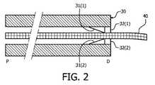
図2に示されるように、本発明の伸縮式内視鏡の一実施例は、第1内視鏡30と、第1内視鏡30の器具経路内に配置された小型第2内視鏡40とを使用する。前記伸縮式内視鏡は、2つのセンサ32と、小型第2内視鏡40を通して網掛けした線により示されるように小型第2内視鏡40に沿って軸方向に整列した複数のマーカとを含む第2内視鏡トラッカを使用する。 As shown in FIG. 2, an embodiment of the telescopic endoscope of the present invention includes a
図10ないし12の記載と併せてここで更に説明されるように、本発明は、小型第2内視鏡40全体を追跡するのとは対照的に第1内視鏡30の器具経路の末端Dから伸びる小型第2内視鏡40の部分を追跡することに基づく。したがって、小型第2内視鏡40が、近位方向P又は末端方向Dの何れかに第1内視鏡30内で平行移動されると、センサ32は、前記マーカのシステマティックな感知により、いかなる瞬間でも第1内視鏡30の器具経路の末端Dから伸びる小型第2内視鏡40の部分を感知し、これにより小型第2内視鏡40の伸ばされた部分の追跡を容易化する。センサ32は、前記マーカにより第1内視鏡30の器具経路の末端Dに対する小型第2内視鏡40の角度方向を感知することもでき、小型第2内視鏡40の伸ばされた部分の追跡を更に容易化する。 As further described herein in conjunction with the description of FIGS. 10-12, the present invention provides for the distal end of the instrument path of the
一実施例において、前記マーカは、小型第2内視鏡40の長さに沿って規則的な間隔で配置され、これによりセンサ32は、小型第2内視鏡40が近位方向P(−)又は末端方向D(+)のいずれかに第1内視鏡30内で平行移動される際に、いくつのマーカが通り過ぎたかをカウントし、これにより小型第2内視鏡40の伸ばされた部分を決定する。加えて、異なる角度におけるマーカは、異なって色分けされ、これにより小型第2内視鏡40の角度は、どのように前記異なって色分けされたマーキングが第1内視鏡30の器具経路の末端Dに対して向けられるかにより感知される。 In one embodiment, the markers are arranged at regular intervals along the length of the small
図2の伸縮式内視鏡は、小型第2内視鏡40の伸ばされた部分の感知を支援するのに小型第2内視鏡40の伸ばされた部分の位置及び角度を制御する2つのガイド31を更に使用する。 The telescoping endoscope of FIG. 2 has two controls that control the position and angle of the extended portion of the small
図3に示されるように、本発明の伸縮式内視鏡の1つの代替実施例は、第1内視鏡50及び第1内視鏡50の器具経路内に配置された小型第2内視鏡60を使用する。前記伸縮式内視鏡は、2つのマーカ52と、小型第2内視鏡60を通して網掛けされた線により示される小型第2内視鏡60に沿って軸方向に整列した複数のセンサとを含む第2内視鏡トラッカを更に使用する。 As shown in FIG. 3, one alternative embodiment of the telescopic endoscope of the present invention is a
再び、図10ないし12の記載と併せてここで更に説明されるように、本発明は、小型第2内視鏡60全体を追跡するのと対照的に第1内視鏡50の器具経路の末端Dから伸びる小型第2内視鏡60の部分を追跡することに基づく。したがって、小型第2内視鏡60が、近位方向P又は末端方向Dのいずれかに第1内視鏡50内で平行移動されると、小型第2内視鏡60のセンサは、当技術分野において知られているマーカ52のシステマティックな感知によりいかなる瞬間でも第1内視鏡50の器具経路の末端Dから伸びる小型第2内視鏡60の部分を感知し、これにより小型第2内視鏡60の伸ばされた部分の追跡を容易化する。小型第2内視鏡60のセンサは、マーカ52により第1内視鏡50の器具経路の末端Dに対する小型第2内視鏡60の角度方向を感知することもでき、小型第2内視鏡60の伸ばされた部分の追跡を更に容易化する。 Again, as further described herein in conjunction with the description of FIGS. 10-12, the present invention provides for the instrument path of the
一実施例において、前記センサは、小型第2内視鏡60の長さに沿って規則的な間隔で配置され、これにより小型第2内視鏡60が近位方向P(−)又は末端方向D(+)のいずれかに第1内視鏡50内を平行移動される際に多色マーカ52を通り過ぎる各センサがカウントされ、これにより小型第2内視鏡60の伸ばされた部分を決定する。加えて、異なる角度におけるセンサは、異なる色フィルタを提供することができ、これにより小型第2内視鏡60の角度は、どのように前記異なる色フィルタが第1内視鏡50の器具経路の末端Dに対して向けられるかにより感知される。 In one embodiment, the sensors are regularly spaced along the length of the small
図3の伸縮式内視鏡は、小型第2内視鏡60の伸ばされた部分の感知を支援するのに小型第2内視鏡60の伸ばされた部分の位置及び角度を制御する2つのガイド51を更に使用する。 The telescopic endoscope of FIG. 3 has two controls for controlling the position and angle of the extended portion of the small
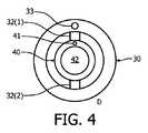
小型第2内視鏡の伸ばされた部分の追跡は、前記小型第2内視鏡の光学的形状感知、又は図10ないし12の記載と併せて更に説明されるように第1内視鏡の基準追跡に基づく。例えば、図4に示されるように、第1内視鏡30(図2)は、第1内視鏡30の追跡経路内に配置された光ファイバ33を含むことができ、小型第2内視鏡40は、小型第2内視鏡40の追跡経路内に配置された光ファイバ41を含むことができる。 The tracking of the stretched portion of the small second endoscope can be achieved by optical shape sensing of the small second endoscope, or as described further in conjunction with the description of FIGS. 10-12. Based on reference tracking. For example, as shown in FIG. 4, the first endoscope 30 (FIG. 2) can include an
本発明の目的に対して、用語"光ファイバ"は、変形センサアレイにより、連続する内部光反射により光を送信/反射するように構造的に構成された品物又は装置としてここで幅広く規定され、アレイの各変形光センサは、特定の波長の光を反射し、他の全ての波長の光を透過するように構造的に構成された品物としてここで幅広く規定され、これにより反射波長は、前記光ファイバに加えられた外部刺激に応じてシフトされることができる。光ファイバの例は、当技術分野において知られているように前記ファイバの長さに沿って統合されたファイバ・ブラッグ・ゲーティングのアレイを組み込む可撓性の光透過ガラス又はプラスチックファイバ、及び当技術分野において知られているように前記ファイバの長さに沿って起こる光学屈折率の変化(例えば、光ファイバに基づくレイリー散乱)を自然にもつ可撓性の光透過ガラス又はプラスチックファイバを含むが、これらに限定されない。 For the purposes of the present invention, the term “optical fiber” is broadly defined herein as an article or device that is structurally configured to transmit / reflect light by a continuous internal light reflection by a deformed sensor array, Each deformation light sensor of the array is broadly defined herein as an item that is structurally configured to reflect light of a specific wavelength and transmit light of all other wavelengths, whereby the reflected wavelength is It can be shifted in response to external stimuli applied to the optical fiber. Examples of optical fibers include flexible light transmissive glass or plastic fibers that incorporate an array of fiber Bragg gating integrated along the length of the fiber as known in the art, and Including flexible light transmissive glass or plastic fibers that naturally have optical refractive index changes (eg, Rayleigh scattering based on optical fibers) that occur along the length of the fiber as known in the art. However, it is not limited to these.
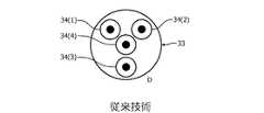
実際に、各光ファイバは、例えば、図5に示される4つのコア34の既知のヘリカル配置を持つ光ファイバ33のマルチコア実施例のような、当技術分野において既知の1つ又は複数のファイバコアを含みうる。 In fact, each optical fiber is one or more fiber cores known in the art, such as, for example, a multi-core embodiment of
図1及び2に戻って参照すると、小型第2内視鏡40、60は、図3に示されるように撮像チャネル及び光ファイバを含むことができるか、又は代替的に、当技術分野において既知のファイバスコープであることができる。例えば、図6は、小型第2内視鏡40のファイバスコープバージョン40aを示す。このバージョン40aの利点は、前記ファイバスコープが、当技術分野において既知の撮像ファイバ及び前記ファイバスコープの固有特性レイリー散乱パターンに基づく光学的形状センサの両方として機能することができることである。 Referring back to FIGS. 1 and 2, the miniature
図7に示されるように、第1内視鏡70及び小型第2内視鏡71の軸アライメントは、小型第2内視鏡の伸ばされた部分の位置及び角度を制御するガイド(例えば、図2のガイド31及び図3のガイド51)の使用に対する代替例を提供する。この代替実施例において、小型第2内視鏡71の3つの突出部72が、第1内視鏡70の溝内にスライド可能に挿入されて、前記内視鏡を軸方向に整列する。代替的には、第1内視鏡70が、小型第2内視鏡71の溝内にスライド可能に挿入される突出部を持つことができる。 As shown in FIG. 7, the axial alignment of the
実際に、前記第2内視鏡トラッカのセンサ及びマーカは、小型第2内視鏡の伸ばされた部分を感知するのに適した物理パラメータに基づくことができる。例えば、前記内視鏡トラッカは、ここに前記された光学的色感知、磁気感知、電気容量感知、インピーダンス感知、磁場強度感知、周波数感知、音響感知、化学的感知及び当技術分野において周知の他の感知技術を使用することができる。 Indeed, the sensors and markers of the second endoscope tracker can be based on physical parameters suitable for sensing the stretched portion of the small second endoscope. For example, the endoscope tracker may be optical color sensing, magnetic sensing, capacitance sensing, impedance sensing, magnetic field strength sensing, frequency sensing, acoustic sensing, chemical sensing and others well known in the art as described herein. Sensing technology can be used.
図8は、レンズ37に戻るように反射される広帯域集束光を小型第2内視鏡44のマーカ45に供給する磨かれた先端を持つボールレンズ37及び光ファイバ36で構成されたセンサを持つ代替的な光学的感知を示す。前記反射光は、マーカ45から反射される主調色を決定するようにスペクトル処理される。前記センサにおける異なる角度位置が異なる色を持つとすると、前記主調色は、第1内視鏡の器具経路内の小型第2内視鏡44の角度を明らかにする。この位置/角度センサは、電流が前記先端に供給されることを要求しないという利点を持つ。更に、前記小型内視鏡におけるマーキングスキームの代替的なタイプが実施されてもよい(例えば、白黒マーカ又はグレイスケールマーカ)。 FIG. 8 has a sensor composed of a
図9は、小型第2内視鏡61の表面から光を供給する複数の光ファイバ62を持つ代替的な光学的感知を示し、これによりマーカ63により反射される光は、小型第2内視鏡61の光学的感知を容易化する。 FIG. 9 shows an alternative optical sensing having a plurality of
光学的追跡システム及び方法の記載は、本発明の更なる理解を容易化するようにここに提供される。 A description of the optical tracking system and method is provided herein to facilitate a further understanding of the invention.
図10に示されるように、本発明の光学的追跡システムは、伸縮式内視鏡トラッカ80と、光学的インタロゲーションコンソール81及びセンサコンソール82と、第1内視鏡84内に配置された光ファイバ83と、小型第2内視鏡86内に配置された光ファイバ85とを使用する。 As shown in FIG. 10, the optical tracking system of the present invention is disposed in a
伸縮式内視鏡トラッカ80は、図12の記載とともに更に説明されるように光ファイバ83及び/又は光ファイバ85の形状を再構成する形状再構成アルゴリズムを実行するように構造的に構成された装置又はシステムとしてここで幅広く規定される。 The
光学的インタロゲーションコンソール81は、光ファイバ83及び85の変形光学センサアレイにより送信された光の連続する内部反射により生成される反射スペクトルの符号化された光学的信号を処理する光ファイバ83及び85を通して光を送信するように構造的に構成された装置又はシステムとしてここで幅広く規定される。一実施例において、光学的インタロゲーションコンソール81は、コヒーレント光源、周波数領域反射率計、及び当技術分野において知られている他の適切な電子機器/装置の構成(図示されない)を使用する。 The
センサコンソール82は、センサ及びマーカの第2内視鏡トラッカにより実施される感知スキームに対して適切な感知アルゴリズムを実行するように構造的に構成された装置又はシステムとしてここで幅広く規定される。 The
まとめて、伸縮式内視鏡トラッカ80、光学的インタロゲーションコンソール81及びセンサコンソール82は、内視鏡84及び86を追跡するフローチャート90(図12)を実施する。 In summary, the
図12を参照すると、光ファイバ83及び85は、前記システムに関連付けられた追跡座標系100に位置合わせされる。 Referring to FIG. 12,
フローチャート90の段S91は、コンソール81の追跡座標系100内の第1内視鏡84の位置、特に追跡座標系100内の第1内視鏡84の末端の位置の決定を含む。特に、光学的インタロゲーションコンソール81は、光ファイバ83を動作し、これにより伸縮式内視鏡トラッカ80による第1内視鏡84の形状の再構成を容易化する。 Step S91 of the flowchart 90 includes determining the position of the
フローチャート90の段S92は、小型第2内視鏡86の伸ばされた部分86aの決定を含む。特に、センサコンソール82は、ここで以前に教示されたように前記第2内視鏡トラッカのセンサを動作し、これにより伸ばされた部分86aを決定する。 Step S92 of the flowchart 90 includes the determination of the stretched
フローチャート90の段S93は、小型第2内視鏡86の伸ばされた部分86aの形状の再構成を含む。特に、光学的インタロゲーションコンソール81は、光ファイバ85を動作し、これによりセンサコンソール82により感知されるように伸縮式内視鏡トラッカ80による延ばされた内視鏡部分86aの再構成を容易化する。 Step S93 of the flowchart 90 includes a reconstruction of the shape of the
フローチャート90の段S94は、伸縮式内視鏡トラッカ80による第1内視鏡84の末端に対する光学的座標系100内の伸ばされた部分86aの位置の決定を含む。 Step S94 of the flowchart 90 includes the determination of the position of the
段S91ないしS94は、内視鏡84及び86の追跡が終了されるまで必要なだけ繰り返される。 Steps S91 to S94 are repeated as necessary until the tracking of the
図11を参照すると、本発明の代替的な光学的追跡システムは、基準トラッカ87を使用し、1つ又は複数のモータ88をオプションとして使用する。 Referring to FIG. 11, an alternative optical tracking system of the present invention uses a
基準トラッカ87は、基準座標系内で内視鏡等を追跡するいかなるタイプの装置又はシステムとしてここで幅広く規定される。基準トラッカ87の例は、電磁追跡システム、光学的追跡システム及び撮像追跡システムを含むが、これらに限定されない。この実施例を用いて、段S91(図12)中の基準座標系内の内視鏡84の位置の決定は、基準トラッカ87により実行され、伸縮式内視鏡トラッカ80に通信される。光学的形状感知システム座標系100は、基準トラッカ87の座標系に位置合わせされ、フローチャート90は、ここに前記されたように進行する。
モータ88は、機械的作動により第1内視鏡84を越えて/内で小型第2内視鏡86を前進/回転するように動作されることができる。好ましくは、モータ88は、前記内視鏡トラッカのセンサからのフィードバックを用いる閉ループ制御によって動作する。モータ88に対するフィードバックは、伸縮式内視鏡トラッカ80により形状決定アルゴリズムの出力から提供されることもできる。このようにして、小型第2内視鏡84の機械的制御は、術前又は術中画像で識別される構造的フィーチャを考慮に入れることにより半自動化又は完全に自動化された形で実行されることができる。 The motor 88 can be operated to advance / rotate the small
図10及び11を参照すると、実際に、内部小型内視鏡86と一緒の配置幾何構成の操作を示す仮想的モデルとしての内視鏡84及び86のライブ視覚化が、実施されることができる。この仮想的モデルは、同時撮像、術前情報又は他の関連する臨床的バイオメトリクス/バイオ情報の上に重ねられた、構成、ダイナミクス、位置/向きに関する誤差/信頼フィードバックに関する当技術分野において既知の瞬間的な情報を提供する。 Referring to FIGS. 10 and 11, in practice, live visualization of
依然として図10及び11を参照すると、内視鏡84及び86の相対的位置/運動は、撮像特性、構成、視覚化モード、データ処理モード等における(半)自動化された変更をトリガする当技術分野において既知の入力ジェスチャとして使用されることができる。 Still referring to FIGS. 10 and 11, the relative position / movement of
図2ないし12の記載から、当業者は、多くの外科手術に対して本発明による2つ以上の細長い装置を持ついかなる種類の伸縮式装置に対する光学的追跡システムを製造及び使用する方法に対する更なる理解を持つ。前記細長い装置の例は、内視鏡、カテーテル及びガイドワイヤを含むが、これらに限定されない。 From the description of FIGS. 2-12, one of ordinary skill in the art will further appreciate how to make and use an optical tracking system for any type of telescopic device having two or more elongated devices according to the present invention for many surgical procedures. With understanding. Examples of the elongate device include, but are not limited to, an endoscope, a catheter, and a guide wire.
本発明の様々な典型的な実施例が、図示及び記載されているが、ここに記載された本発明の典型的な実施例が説明的であり、様々な変更および修正が行われることができ、同等物が、本発明の真の範囲から逸脱することなしにその要素に対して置き換えられることができると、当業者により理解される。例えば、本発明は、FBGに関してここで論じられるが、FBG又は他の光学の存在とともに又はなしで、逆散乱、光ファイバ力感知、ファイバ場所センサ又はレイリー散乱を使用してファイバ内の1つ又は複数のセクションにおける変化の検出から感知又は位置特定を一般に含む形状感知又は位置特定に対するファイバ光学を含むことが理解される。加えて、多くの修正例が、中心範囲から逸脱することなしに本発明の教示を適応させるように行われることができる。したがって、本発明が、本発明を実行することを意図されるベストモードとして開示された特定の実施例に限定されず、本発明が、添付の請求項の範囲に入る全ての実施例を含むことが意図される。 While various exemplary embodiments of the present invention have been illustrated and described, the exemplary embodiments of the present invention described herein are illustrative and various changes and modifications can be made. It will be understood by those skilled in the art that equivalents may be substituted for the elements without departing from the true scope of the invention. For example, the present invention will be discussed herein with respect to FBGs, but with or without the presence of FBG or other optics, one or the other in the fiber using backscattering, fiber optic force sensing, fiber location sensors or Rayleigh scattering. It is understood to include fiber optics for shape sensing or localization that generally includes sensing or locating from detection of changes in multiple sections. In addition, many modifications may be made to adapt the teachings of the invention without departing from the central scope. Accordingly, the invention is not limited to the specific embodiments disclosed as the best mode intended to carry out the invention, but the invention includes all embodiments that fall within the scope of the appended claims. Is intended.
Claims (20)
Translated fromJapanese前記第1内視鏡の前記器具経路内に配置された小型第2内視鏡と、
前記第1内視鏡の前記器具経路の末端から伸びる前記小型第2内視鏡の部分を感知する少なくとも1つのセンサ及び少なくとも1つのマーカを含む内視鏡トラッカと、
を有する伸縮式内視鏡。A first endoscope having an instrument path;
A small second endoscope disposed in the instrument path of the first endoscope;
An endoscope tracker including at least one sensor and at least one marker for sensing a portion of the small second endoscope extending from a distal end of the instrument path of the first endoscope;
Telescopic endoscope having
前記少なくとも1つのマーカが、前記小型第2内視鏡と一体化される、
請求項1に記載の伸縮式内視鏡。The at least one sensor is integrated with the first endoscope;
The at least one marker is integrated with the small second endoscope;
The telescopic endoscope according to claim 1.
前記少なくとも1つのセンサが、前記小型第2内視鏡と一体化される、
請求項1に記載の伸縮式内視鏡。The at least one marker is integrated with the first endoscope;
The at least one sensor is integrated with the small second endoscope;
The telescopic endoscope according to claim 1.
器具経路を持つ第1内視鏡、
前記第1内視鏡の前記器具経路内に配置された小型第2内視鏡、及び
前記第1内視鏡の前記器具経路の末端から伸びる前記小型第2内視鏡の部分を感知する少なくとも1つのセンサ及び少なくとも1つのマーカを含む内視鏡トラッカ、
を含む当該伸縮式内視鏡と、
前記小型第2内視鏡の伸ばされた部分の感知をモニタリングするように前記少なくとも1つのセンサと通信するセンサコンソールと、
を有する光学的追跡システム。A telescopic endoscope,
A first endoscope having an instrument path;
A small second endoscope disposed in the instrument path of the first endoscope, and at least a portion of the small second endoscope extending from a distal end of the instrument path of the first endoscope; An endoscopic tracker including one sensor and at least one marker;
The telescopic endoscope including:
A sensor console in communication with the at least one sensor to monitor the sensing of the stretched portion of the miniature second endoscope;
An optical tracking system.
前記光学的インタロゲーションコンソールが、前記小型第2内視鏡の形状を感知するように少なくとも1つの第2光ファイバと通信し、
前記伸縮式内視鏡トラッカが、前記内視鏡トラッカ及び前記光学的インタロゲーションコンソールにより感知される前記小型第2内視鏡の伸ばされた部分の形状を再構成するように前記センサコンソール及び前記光学的インタロゲーションコンソールと通信する、
請求項11に記載の光学的追跡システム。The system further comprises a telescopic endoscope tracker and an optical interrogation console;
The optical interrogation console communicates with at least one second optical fiber to sense the shape of the miniature second endoscope;
The sensor console so that the telescopic endoscope tracker reconfigures the shape of the extended portion of the small second endoscope sensed by the endoscope tracker and the optical interrogation console; Communicating with the optical interrogation console;
The optical tracking system of claim 11.
前記光学的インタロゲーションコンソールが、前記第1内視鏡の形状を感知するように前記少なくとも1つの第1光ファイバと通信し、
前記伸縮式内視鏡トラッカが、前記光学的インタロゲーションコンソールにより感知される前記第1内視鏡の形状を再構成するように前記光学的インタロゲーションコンソールと通信する、
請求項12に記載の光学的追跡システム。The first endoscope includes at least one first optical fiber;
The optical interrogation console communicates with the at least one first optical fiber to sense the shape of the first endoscope;
The telescopic endoscope tracker communicates with the optical interrogation console to reconfigure the shape of the first endoscope sensed by the optical interrogation console;
The optical tracking system of claim 12.
前記伸縮式内視鏡トラッカが、前記第1内視鏡の形状再構成に対する前記小型第2内視鏡の伸ばされた部分の形状再構成に応じて前記追跡座標系内の前記第1内視鏡の末端に対する前記小型第2内視鏡の位置を決定するように動作可能である、
請求項13に記載の光学的追跡システム。The telescopic endoscope tracker is operable to determine a position of the first endoscope in a tracking coordinate system in response to a shape reconstruction of the first endoscope;
The telescopic endoscope tracker has the first endoscope in the tracking coordinate system in response to a shape reconstruction of an extended portion of the small second endoscope with respect to a shape reconstruction of the first endoscope. Operable to determine the position of the small second endoscope relative to the end of the mirror;
The optical tracking system of claim 13.
前記伸縮式内視鏡トラッカが、前記追跡座標系内の前記第1内視鏡の場所に対する前記小型第2内視鏡の伸ばされた部分の形状再構成に応じて前記追跡座標系内の前記第1内視鏡の末端に対する前記小型第2内視鏡の位置を決定するように前記基準トラッカと通信する、
請求項12に記載の光学的追跡システム。The system comprises a reference tracker for determining the position of the first endoscope in a tracking coordinate system;
The telescopic endoscope tracker is adapted to reshape the extended portion of the small second endoscope relative to the location of the first endoscope in the tracking coordinate system in the tracking coordinate system. Communicating with the reference tracker to determine the position of the small second endoscope relative to the distal end of the first endoscope;
The optical tracking system of claim 12.
前記第1内視鏡の器具経路内に前記小型第2内視鏡を配置するステップと、
前記第1内視鏡の前記器具経路の末端から伸びる前記小型第2内視鏡の部分を感知するように前記内視鏡トラッカを動作するステップと、
を有する光学的追跡方法。In an optical tracking method for a telescopic endoscope including a first endoscope, a small second endoscope, and an endoscope tracker,
Placing the small second endoscope in the instrument path of the first endoscope;
Operating the endoscope tracker to sense a portion of the small second endoscope extending from a distal end of the instrument path of the first endoscope;
An optical tracking method.
前記内視鏡トラッカにより感知される前記小型第2内視鏡の伸ばされた部分の形状を再構成するステップと、
を有する、請求項16に記載の光学的追跡方法。Sensing the shape of the small second endoscope;
Reconfiguring the shape of the stretched portion of the small second endoscope sensed by the endoscope tracker;
The optical tracking method according to claim 16, comprising:
前記第1内視鏡の形状を再構成するステップと、
を有する、請求項17に記載の光学的追跡方法。Sensing the shape of the first endoscope;
Reconfiguring the shape of the first endoscope;
The optical tracking method according to claim 17, comprising:
前記第1内視鏡の形状再構成に対する前記小型第2内視鏡の伸ばされた部分の形状再構成に応じて前記追跡座標系内の前記第1内視鏡の末端に対する前記小型第2内視鏡の位置を決定するステップと、
を有する、請求項18に記載の光学的追跡方法。Determining a position of the first endoscope in a tracking coordinate system in accordance with a shape reconstruction of the first endoscope;
The small second internal to the distal end of the first endoscope in the tracking coordinate system in response to the shape reconstruction of the extended portion of the small second endoscope with respect to the shape reconstruction of the first endoscope Determining the position of the endoscope;
The optical tracking method according to claim 18, comprising:
前記追跡座標系内の前記第1内視鏡の決定された場所に対する前記小型第2内視鏡の伸ばされた部分の形状再構成に応じて前記追跡座標系内の前記第1内視鏡の末端に対する前記小型第2内視鏡の位置を決定するステップと、
を有する、請求項17に記載の光学的追跡方法。Determining a position of the first endoscope in a tracking coordinate system in response to a reference tracking;
The first endoscope in the tracking coordinate system in response to a shape reconstruction of the stretched portion of the small second endoscope with respect to the determined location of the first endoscope in the tracking coordinate system. Determining the position of the small second endoscope with respect to the distal end;
The optical tracking method according to claim 17, comprising:
Applications Claiming Priority (3)
| Application Number | Priority Date | Filing Date | Title |
|---|---|---|---|
| US201161437387P | 2011-01-28 | 2011-01-28 | |
| US61/437,387 | 2011-01-28 | ||
| PCT/IB2012/050112WO2012101532A1 (en) | 2011-01-28 | 2012-01-10 | Optical sensing for relative tracking of endoscopes |
Publications (2)
| Publication Number | Publication Date |
|---|---|
| JP2014507987Atrue JP2014507987A (en) | 2014-04-03 |
| JP6259661B2 JP6259661B2 (en) | 2018-01-10 |
Family
ID=45560944
Family Applications (1)
| Application Number | Title | Priority Date | Filing Date |
|---|---|---|---|
| JP2013550968AExpired - Fee RelatedJP6259661B2 (en) | 2011-01-28 | 2012-01-10 | Optical tracking system |
Country Status (5)
| Country | Link |
|---|---|
| US (1) | US20130310645A1 (en) |
| EP (1) | EP2667762A1 (en) |
| JP (1) | JP6259661B2 (en) |
| CN (1) | CN103501678B (en) |
| WO (1) | WO2012101532A1 (en) |
Families Citing this family (7)
| Publication number | Priority date | Publication date | Assignee | Title |
|---|---|---|---|---|
| US9949615B2 (en)* | 2011-09-21 | 2018-04-24 | Boston Scientific Scimed, Inc. | Systems and methods for preventing laser fiber misfiring within endoscopic access devices |
| CN114795471A (en) | 2015-04-06 | 2022-07-29 | 直观外科手术操作公司 | System and method for registration compensation in image-guided surgery |
| US11589925B2 (en)* | 2015-09-16 | 2023-02-28 | Koninklijke Philips N.V. | Medical system using optical shape sensing fiber for triggering an event |
| WO2018035122A1 (en) | 2016-08-16 | 2018-02-22 | Intuitive Surgical Operations, Inc. | Augmented accuracy using large diameter shape fiber |
| US10695539B2 (en)* | 2017-03-24 | 2020-06-30 | Myodynamics, LLC | Device for measuring length of tubular body structure |
| CN108814717B (en)* | 2018-06-29 | 2020-10-27 | 微创(上海)医疗机器人有限公司 | Surgical robot system |
| EP3861920A1 (en)* | 2020-02-05 | 2021-08-11 | Erbe Elektromedizin GmbH | Surgical instrument with a position detection device |
Citations (6)
| Publication number | Priority date | Publication date | Assignee | Title |
|---|---|---|---|---|
| JPH05285091A (en)* | 1992-04-10 | 1993-11-02 | Olympus Optical Co Ltd | Bending apparatus |
| US20070225559A1 (en)* | 2006-03-21 | 2007-09-27 | Boston Scientific Scimed, Inc. | Vision catheter having electromechanical navigation |
| JP2008173397A (en)* | 2007-01-22 | 2008-07-31 | Olympus Corp | Endoscope system |
| JP2009279249A (en)* | 2008-05-23 | 2009-12-03 | Olympus Medical Systems Corp | Medical device |
| WO2010128605A1 (en)* | 2009-05-07 | 2010-11-11 | コニカミノルタオプト株式会社 | Optical characteristic measuring probe |
| WO2010140441A1 (en)* | 2009-06-01 | 2010-12-09 | オリンパスメディカルシステムズ株式会社 | Medical equipment system and method for calibrating medical instrument |
Family Cites Families (47)
| Publication number | Priority date | Publication date | Assignee | Title |
|---|---|---|---|---|
| US4146019A (en)* | 1976-09-30 | 1979-03-27 | University Of Southern California | Multichannel endoscope |
| US5470330A (en)* | 1984-12-07 | 1995-11-28 | Advanced Interventional Systems, Inc. | Guidance and delivery system for high-energy pulsed laser light |
| SE457052B (en)* | 1986-03-12 | 1988-11-28 | Jan Gillquist | INSTRUMENTS FOR MEASUREMENT OF DISTANCE BETWEEN BENDLES IN A KNEE JOINT |
| JP3034898B2 (en)* | 1990-04-04 | 2000-04-17 | オリンパス光学工業株式会社 | Endoscope device |
| US5840024A (en)* | 1993-10-18 | 1998-11-24 | Olympus Optical Co., Ltd. | Endoscope form detecting apparatus in which coil is fixedly mounted by insulating member so that form is not deformed within endoscope |
| US5836869A (en)* | 1994-12-13 | 1998-11-17 | Olympus Optical Co., Ltd. | Image tracking endoscope system |
| US5728044A (en)* | 1995-03-10 | 1998-03-17 | Shan; Yansong | Sensor device for spacial imaging of endoscopes |
| US7037258B2 (en)* | 1999-09-24 | 2006-05-02 | Karl Storz Imaging, Inc. | Image orientation for endoscopic video displays |
| DE19964016B4 (en)* | 1999-12-30 | 2005-06-23 | Brainlab Ag | Method and device for positioning a body with a position sensor for irradiation |
| US6817973B2 (en)* | 2000-03-16 | 2004-11-16 | Immersion Medical, Inc. | Apparatus for controlling force for manipulation of medical instruments |
| US7819799B2 (en)* | 2000-03-16 | 2010-10-26 | Immersion Medical, Inc. | System and method for controlling force applied to and manipulation of medical instruments |
| JP4488280B2 (en)* | 2002-06-07 | 2010-06-23 | オリンパス株式会社 | Endoscopic treatment tool and endoscope apparatus |
| US7697972B2 (en)* | 2002-11-19 | 2010-04-13 | Medtronic Navigation, Inc. | Navigation system for cardiac therapies |
| US20040176683A1 (en)* | 2003-03-07 | 2004-09-09 | Katherine Whitin | Method and apparatus for tracking insertion depth |
| US7715896B2 (en)* | 2003-03-21 | 2010-05-11 | Boston Scientific Scimed, Inc. | Systems and methods for internal tissue penetration |
| JP3922284B2 (en)* | 2004-03-31 | 2007-05-30 | 有限会社エスアールジェイ | Holding device |
| US20060149129A1 (en)* | 2005-01-05 | 2006-07-06 | Watts H D | Catheter with multiple visual elements |
| JP4745833B2 (en)* | 2005-01-18 | 2011-08-10 | Hoya株式会社 | Electronic endoscope system |
| US8611983B2 (en)* | 2005-01-18 | 2013-12-17 | Philips Electronics Ltd | Method and apparatus for guiding an instrument to a target in the lung |
| US7956887B2 (en)* | 2005-02-17 | 2011-06-07 | Karl Storz Imaging, Inc. | Image orienting coupling assembly |
| US8182433B2 (en)* | 2005-03-04 | 2012-05-22 | Endosense Sa | Medical apparatus system having optical fiber load sensing capability |
| JP4813112B2 (en)* | 2005-07-08 | 2011-11-09 | オリンパスメディカルシステムズ株式会社 | Endoscope device |
| JP4708963B2 (en)* | 2005-11-09 | 2011-06-22 | Hoya株式会社 | Endoscope insertion part shape grasping system |
| JP5044126B2 (en)* | 2006-02-23 | 2012-10-10 | オリンパス株式会社 | Endoscope observation apparatus and operation method of endoscope for image formation |
| JP2007275437A (en)* | 2006-04-10 | 2007-10-25 | Olympus Medical Systems Corp | Endoscope cleaning / disinfecting device, cleaning brush unit, brush housing unit |
| JP4868945B2 (en)* | 2006-05-31 | 2012-02-01 | オリンパスメディカルシステムズ株式会社 | Endoscope |
| US20080009712A1 (en)* | 2006-06-16 | 2008-01-10 | Adams Mark L | Apparatus and Methods for Maneuvering a Therapeutic Tool Within a Body Lumen |
| JP4891006B2 (en)* | 2006-09-06 | 2012-03-07 | オリンパス株式会社 | Endoscope device |
| US7824328B2 (en)* | 2006-09-18 | 2010-11-02 | Stryker Corporation | Method and apparatus for tracking a surgical instrument during surgery |
| US20100020163A1 (en)* | 2006-12-11 | 2010-01-28 | Olympus Corporation | Fluorescence endoscope |
| US20080147018A1 (en)* | 2006-12-15 | 2008-06-19 | Squilla John R | Laparoscopic cannula with camera and lighting |
| JP4246233B2 (en)* | 2006-12-21 | 2009-04-02 | オリンパスメディカルシステムズ株式会社 | Visceral anastomosis marker and marker placement device |
| EP2626030A3 (en)* | 2007-08-14 | 2017-03-08 | Koninklijke Philips N.V. | Robotic instrument systems and methods utilizing optical fiber sensors |
| JP4672031B2 (en)* | 2008-01-31 | 2011-04-20 | オリンパスメディカルシステムズ株式会社 | Medical instruments |
| JP5372407B2 (en)* | 2008-05-23 | 2013-12-18 | オリンパスメディカルシステムズ株式会社 | Medical equipment |
| WO2010073135A1 (en)* | 2008-12-23 | 2010-07-01 | Koninklijke Philips Electronics, N.V. | Nested cannula configuration for use with endoscope |
| WO2010092495A1 (en)* | 2009-02-11 | 2010-08-19 | Koninklijke Philips Electronics, N.V. | Method and system of tracking and mapping in a medical procedure |
| US20110137127A1 (en)* | 2009-12-08 | 2011-06-09 | Ai Medical Devices, Inc. | Dual screen intubation system |
| US9345397B2 (en)* | 2010-09-21 | 2016-05-24 | The Johns Hopkins University | Optical sensing system for cochlear implant surgery |
| WO2012106310A1 (en)* | 2011-02-04 | 2012-08-09 | The Penn State Research Foundation | Method and device for determining the location of an endoscope |
| US8579800B2 (en)* | 2011-03-22 | 2013-11-12 | Fabian Emura | Systematic chromoendoscopy and chromocolonoscopy as a novel systematic method to examine organs with endoscopic techniques |
| JP5830270B2 (en)* | 2011-05-24 | 2015-12-09 | オリンパス株式会社 | Endoscope apparatus and measuring method |
| JP5846763B2 (en)* | 2011-05-24 | 2016-01-20 | オリンパス株式会社 | Endoscope device |
| JP5973727B2 (en)* | 2011-12-28 | 2016-08-23 | オリンパス株式会社 | Stereoscopic endoscope apparatus, stereoscopic endoscope system, and stereoscopic endoscope robot |
| GB2518124B (en)* | 2013-05-30 | 2018-04-25 | Aircraft Medical Ltd | Video laryngoscope and video laryngoscope insertion section |
| JP6091410B2 (en)* | 2013-12-26 | 2017-03-08 | オリンパス株式会社 | Endoscope apparatus operating method and endoscope system |
| US20150297308A1 (en)* | 2014-04-18 | 2015-10-22 | Enterogauge, Llc | Enteroscope measuring device |
- 2012
- 2012-01-10USUS13/982,279patent/US20130310645A1/ennot_activeAbandoned
- 2012-01-10WOPCT/IB2012/050112patent/WO2012101532A1/enactiveApplication Filing
- 2012-01-10EPEP12702075.8Apatent/EP2667762A1/ennot_activeWithdrawn
- 2012-01-10JPJP2013550968Apatent/JP6259661B2/ennot_activeExpired - Fee Related
- 2012-01-10CNCN201280006519.XApatent/CN103501678B/ennot_activeExpired - Fee Related
Patent Citations (6)
| Publication number | Priority date | Publication date | Assignee | Title |
|---|---|---|---|---|
| JPH05285091A (en)* | 1992-04-10 | 1993-11-02 | Olympus Optical Co Ltd | Bending apparatus |
| US20070225559A1 (en)* | 2006-03-21 | 2007-09-27 | Boston Scientific Scimed, Inc. | Vision catheter having electromechanical navigation |
| JP2008173397A (en)* | 2007-01-22 | 2008-07-31 | Olympus Corp | Endoscope system |
| JP2009279249A (en)* | 2008-05-23 | 2009-12-03 | Olympus Medical Systems Corp | Medical device |
| WO2010128605A1 (en)* | 2009-05-07 | 2010-11-11 | コニカミノルタオプト株式会社 | Optical characteristic measuring probe |
| WO2010140441A1 (en)* | 2009-06-01 | 2010-12-09 | オリンパスメディカルシステムズ株式会社 | Medical equipment system and method for calibrating medical instrument |
Also Published As
| Publication number | Publication date |
|---|---|
| JP6259661B2 (en) | 2018-01-10 |
| CN103501678B (en) | 2017-04-05 |
| CN103501678A (en) | 2014-01-08 |
| US20130310645A1 (en) | 2013-11-21 |
| CN103501678A8 (en) | 2016-11-02 |
| EP2667762A1 (en) | 2013-12-04 |
| WO2012101532A1 (en) | 2012-08-02 |
Similar Documents
| Publication | Publication Date | Title |
|---|---|---|
| US12295718B2 (en) | Steerable flexible needle with embedded shape sensing | |
| US12390123B2 (en) | Systems and methods for configuring components in a minimally invasive instrument | |
| JP6259661B2 (en) | Optical tracking system | |
| US20220346751A1 (en) | Systems and methods for interventional procedure planning | |
| US20220378316A1 (en) | Systems and methods for intraoperative segmentation | |
| US10660509B2 (en) | System for controlling an instrument using shape sensors | |
| JP5826770B2 (en) | Method and system for absolute three-dimensional measurement using a shape sensor with low sensitivity to torsion | |
| US20170265946A1 (en) | Shape sensed robotic ultrasound for minimally invasive interventions | |
| JP2019522228A (en) | Method and system for optically connecting an optical fiber sensor to an optical shape sensing console | |
| CA2955036C (en) | Tip deformation measuring apparatus for medical procedures |
Legal Events
| Date | Code | Title | Description |
|---|---|---|---|
| A521 | Request for written amendment filed | Free format text:JAPANESE INTERMEDIATE CODE: A523 Effective date:20141226 | |
| A621 | Written request for application examination | Free format text:JAPANESE INTERMEDIATE CODE: A621 Effective date:20141226 | |
| A977 | Report on retrieval | Free format text:JAPANESE INTERMEDIATE CODE: A971007 Effective date:20151016 | |
| A131 | Notification of reasons for refusal | Free format text:JAPANESE INTERMEDIATE CODE: A131 Effective date:20151020 | |
| A521 | Request for written amendment filed | Free format text:JAPANESE INTERMEDIATE CODE: A523 Effective date:20151210 | |
| A131 | Notification of reasons for refusal | Free format text:JAPANESE INTERMEDIATE CODE: A131 Effective date:20160607 | |
| A601 | Written request for extension of time | Free format text:JAPANESE INTERMEDIATE CODE: A601 Effective date:20160906 | |
| A521 | Request for written amendment filed | Free format text:JAPANESE INTERMEDIATE CODE: A523 Effective date:20161207 | |
| RD04 | Notification of resignation of power of attorney | Free format text:JAPANESE INTERMEDIATE CODE: A7424 Effective date:20170214 | |
| A02 | Decision of refusal | Free format text:JAPANESE INTERMEDIATE CODE: A02 Effective date:20170221 | |
| A521 | Request for written amendment filed | Free format text:JAPANESE INTERMEDIATE CODE: A523 Effective date:20170612 | |
| A911 | Transfer to examiner for re-examination before appeal (zenchi) | Free format text:JAPANESE INTERMEDIATE CODE: A911 Effective date:20170620 | |
| A131 | Notification of reasons for refusal | Free format text:JAPANESE INTERMEDIATE CODE: A131 Effective date:20170814 | |
| A521 | Request for written amendment filed | Free format text:JAPANESE INTERMEDIATE CODE: A523 Effective date:20171006 | |
| TRDD | Decision of grant or rejection written | ||
| A01 | Written decision to grant a patent or to grant a registration (utility model) | Free format text:JAPANESE INTERMEDIATE CODE: A01 Effective date:20171205 | |
| A61 | First payment of annual fees (during grant procedure) | Free format text:JAPANESE INTERMEDIATE CODE: A61 Effective date:20171211 | |
| R150 | Certificate of patent or registration of utility model | Ref document number:6259661 Country of ref document:JP Free format text:JAPANESE INTERMEDIATE CODE: R150 | |
| LAPS | Cancellation because of no payment of annual fees |